

Viqua SHF-140, SHFM-140, SHF-180, SHFM-180, SHF-290 Owner's Manual
...
Owner’s Manual
Powered by
Models:
SHF-140, SHFM-140,
SHF-180, SHFM-180
SHF-290, SHFM-290
425 Clair Rd. W, Guelph, Ontario, Canada N1L 1R1
t. (+1) 519.763.1032 • tf. (+1).800.265.7246 (US and Canada only)
t. (+31) 73 747 0144 (Europe only) • f. (+1) 519.763.5069
e-mail: info@viqua.com
www.viqua.com
520189-R_RevL

Congratulations on the purchase of your ultraviolet (UV) water disinfection
system! This system uses the most advanced UV technology on the market and is
designed to provide you with years of trouble free operation with minimal maintenance
required to protect your drinking water from microbiological contaminants.
To ensure ongoing disinfection of your water, UV lamps need to be replaced annually
with VIQUA factory-supplied replacements. VIQUA lamps are the result of extensive
development resulting in a highly efficient disinfection platform with extremely stable UV
output over the entire 9000 hour lifetime. Its success has led to a proliferation of nongenuine copies in the market.
The UV lamp is the heart of the disinfection system, and there should be no compromise
when it's time for a replacement.
Why should you insist on genuine factory supplied VIQUA replacement lamps?
• Use of widely available, non-genuine, replacement lamps has been shown to
damage the control module of VIQUA UV disinfection equipment.
• An increasing number of calls to VIQUA Technical Support are connected with nongenuine lamps being used (unknowingly) as replacements.
• Damage arising from the use of non-genuine lamps poses a safety risk and is not
covered by equipment warranty.
• Unless the UV equipment is equipped with a UV sensor (monitor), it is not possible to
verify the UV (invisible) output of replacement lamps.
• Similar appearance to the original lamp and the presence of (visible) blue light does
not mean equivalent disinfection performance.
• VIQUA replacement lamps undergo rigorous performance testing and strict quality
control processes to ensure that the safety and performance certifications of the
original equipment are not compromised.
So, you can see that it's simply not worth the risk! Insist on genuine VIQUA replacement
lamps.
2
Section 1 Safety Information
Hg
UV
These are the original instructions. Please read this entire manual before operating this equipment. Pay attention to all
danger, warning, and caution st atement s in this manual. Failure to do so could result in serious personal injury or damage to
the equipment.
Make sure that the protection provided by this equipment is not impaired. Do not use or install this equipment in any manner
other than that specified in the installation manual.
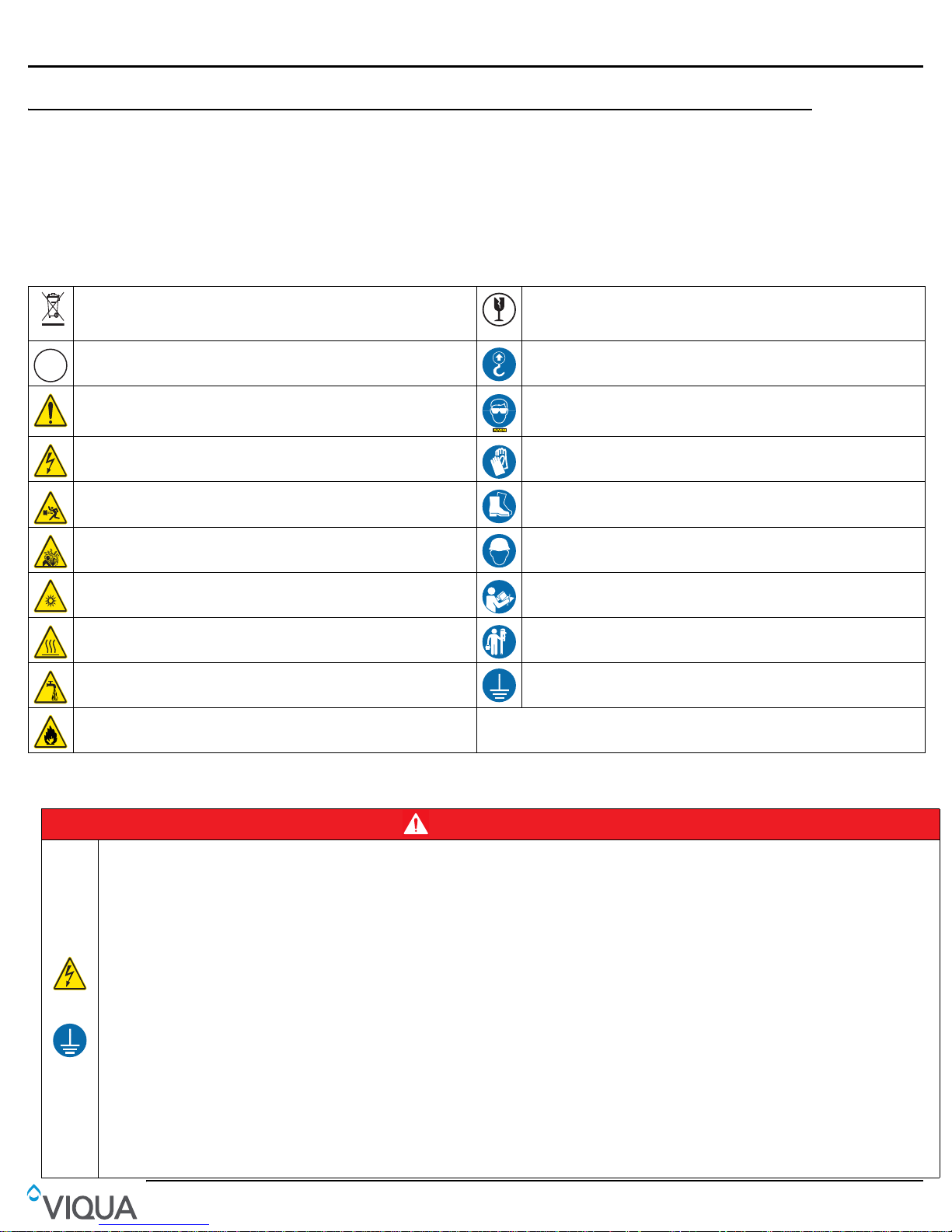
1.1 Potential Hazards
Read all labels and tags attached to the system. Personal injury or damage to the system could occur if not observed.
Waste electrical and electronic equipment (WEEE). This symbol indicates that
you should not discard wasted electrical or electronic equipment (WEEE) in the
trash. For proper disposal, contact your local recycling/reuse or hazardous waste
center.
This symbol indicates there is Mercury present. This symbol indicates to secure the device with a safety device / hook.
Safety Information
This symbol indicates that the contents of the transport package are fragile and
the package should be handled with care.
This is the safety alert symbol. Obey all safety messages that follow this symbol
to avoid potential injury. When on the equipment, refer to the Operational and
Maintenance manual for additional safety information.
This symbol indicates a risk of electrical shock and/or electrocution exists. This symbol indicates gloves must be worn.
This symbol indicates the marked equipment may contain a component that can
eject forcibly. Obey all procedures to safely depressurize.
This symbol indicates the system is under pressure. This symbol indicates a hard hat must be worn.
This symbol indicates there is a potential UV hazard. Proper protection must be
worn.
This symbol indicates the marked item could be hot and should not be touched
without care.
This symbol indicates there is a potential for VERY hot water when flow is
started.
This symbol indicates not to store any combustible or flammable material close to
the system.
Warning: This product may contain chemicals known to the State of California to cause cancer and birth defects or other reproductive harm.
This symbol indicates safety glasses with side protection is required for
protection against UV ex po sure.
This symbol indicates safety boots must be worn.
This symbol indicates the operator must read all available documentation to
perform required procedures.
This symbol indicates the plumber must use copper piping.
Cu
This symbol indicates that the system should only be connected to a properly
grounded, grounding-type controller receptacle that is protected by a Ground
Fault Circuit Interrupter (GFCI).
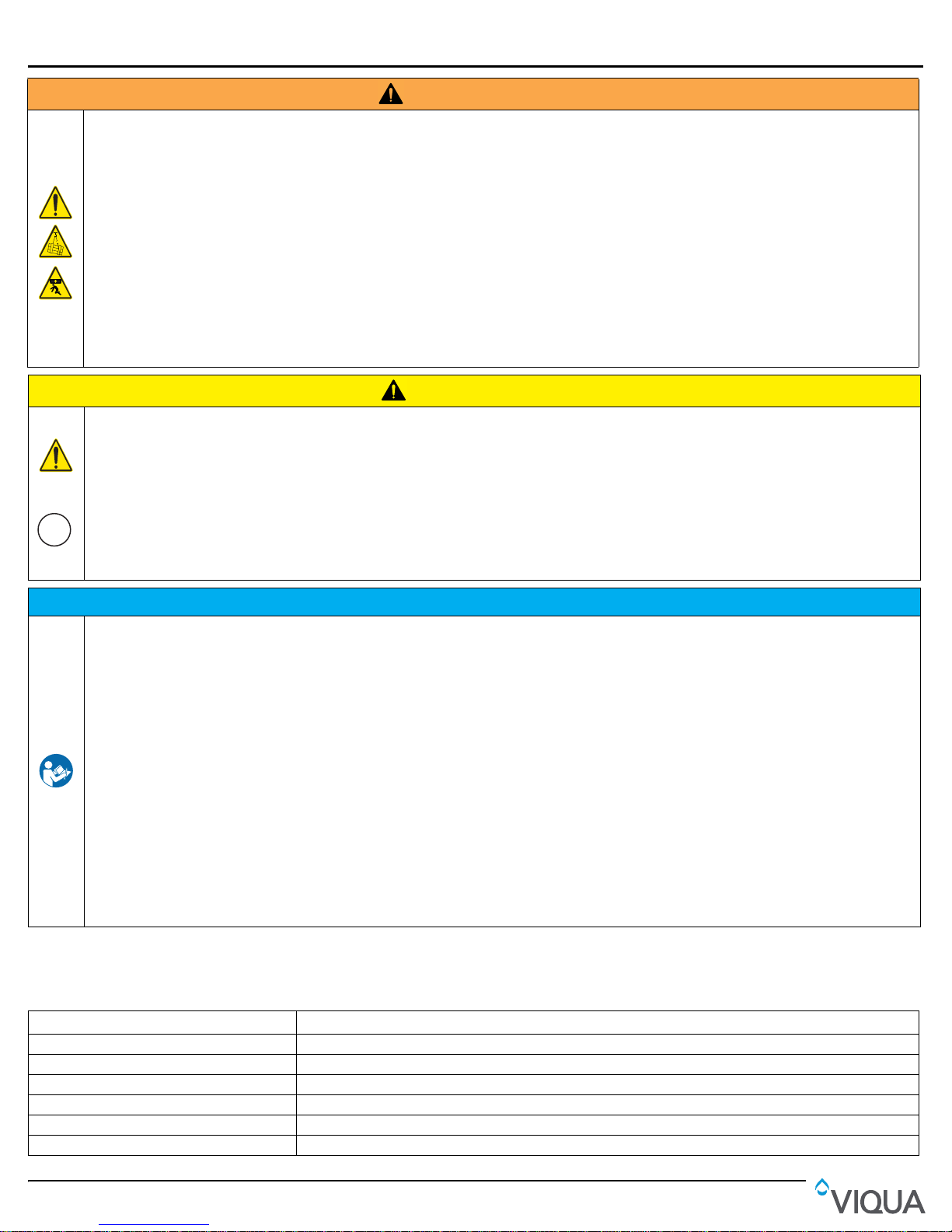
1.2 Safety Precautions
DANGER
Failure to follow these instructions will result in serious injury or death.
• Electric Shock: To avoid possible electric shock, special care should be taken since water is present near the electrical equipment. Unless a
situation is encountered that is explicitly addressed by the provided maintenance and troubleshooting sections, do not attempt repairs yourself,
refer to an authorized service facility.
• GROUNDING: This product must be grounded. If it should malfunction or breakdown, grounding provides a path of least resistance for electric
current to reduce the risk of electrical shock. This system is equipped with a cord having an equipment-grounding conductor and a grounding plug.
The plug must be plugged into an appropriate outlet that is properly installed and grounded in accordance with all local codes and ordinances.
Improper connection of the equipment-grounding conductor can result in a risk of electrocution. Check with a qualified electrician or service
personnel if you are in doubt as to whether the outlet is properly grounded. Do not modify the plug provided with this system – if it does not fit in the
outlet, have a proper outlet installed by a qualified electrician. Do not use any type of adapter with this system.
• GROUND FAULT CIRCUIT INTERRUPTER PROTECTION: To comply with the National Electrical Code (NFPA 70) and to provide additional
protection from the risk of electric shock, this system should only be connected to a properly grounded, grounding-type controller receptacle that is
protected by a Ground Fault Circuit Interrupter (GFCI) or to a residual current device (RCD) having a rated residual operating current not exceeding
30 mA. Inspect operation of GFCI as per manufacturer’s suggested maintenance schedule.
• DO NOT operate the disinfection system if it has a damaged cord or plug, if it is malfunctioning or if it has been dropped or damaged in any manner.
• DO NOT use this disinfection system for other than intended use (potable water applications). The use of attachments not recommended or sold by
the manufacturer / distributor may cause an unsafe condition.
• DO NOT install this disinfection system where it will be exposed to the weather or to temperatures below freezing.
• DO NOT store this disinfection system where it will be exposed to the weather.
• DO NOT store this disinfection system where it will be exposed to temperatures below freezing unless all water has been drained from it and the
water supply has been disconnected.
3
Safety Information
Hg
• During extended periods of no water flow, the water in your chamber can become very hot (Approx. 60 °C) and potentially lead to scalding. It is
recommended to run your water until this hot water has been purged from your chamber. Do not allow water to contact your skin during this time.
To eliminate this condition, a temperature management valve can be installed at the outlet of your UV system.
• Do not pass water through the UV system for a minimum of 5 minutes after applying power (including after power interruptions) to avoid passing
under-treated water that may, in rare instances, pose health hazards.
• This system contains a UV Lamp. Do not operate the UV Lamp when it is removed from the chamber. Unintended use or damage of the system
may result in the exposure of dangerous UV radiation. UV radiation may, even in little doses, cause harm to the eyes and skin.
• Changes or modifications made to this system without the consent of the manufacturer could render the system unsafe for operation and may void
the manufacturer's warranty.
Body Crush Hazard
• Failure to follow these instructions could result in serious injury or death due to improper lifting procedures, underrated lifting equipment and,
moving parts.
• ALWAYS secure with safety device.
• ALWAYS stay clear of elevated loads.
• ALWAYS comply with local safety regulations.
Failure to follow these instructions could result in minor or moderate injury.
• Carefully examine the disinfection system after installation. It should not be plugged in if there is water on parts not intended to be wet such as, the
controller or lamp connector.
• Due to thermal expansion concerns and potential material degradation due to UV exposure, it is recommended to use metal fittings and at least
10" of copper pipe on the outlet of your UV chamber.
For industrial use only.
• During normal operation, Control Panel must be locked using the key and padlock supplied.
• Hg EXPOSURE: The UV lamp contains mercury. If the lamp breaks, then avoid inhalation or ingestion of the debris and avoid exposure to eyes
and skin. Never use a vacuum cleaner to clean up a broken lamp as this may scatter the spilled mercury. Obey local regulations and guidelines for
the removal and disposal of mercury waste.
WAR NI NG
CAUTION
NOTICE
• The UV lamp inside the disinfection system is rated at an effective life of approximately 9000 hours. To ensure continuous protection, replace the
UV lamp annually.
• The UV system is not to be used or played with by children. Persons with reduced physical, sensory or mental capabilities, or lack of experience
and knowledge, are also not to handle the UV system unless they have been given supervision or instruction.
• This system is intended to be permanently connected to the water lines.
• This system is not intended to be used in or above water or outdoors or used in swimming pools when persons are in the pool.
• EXTENSION CORDS: If an extension cord is necessary, use only 3-wire extension cords that have 3-prong grounding-type plugs and 3-pole cord
connectors that accept the plug from this system. Use only extension cords that are intended for outdoor use. Use only extension cords having an
electrical rating not less than the rating of the system. A cord rated for less amperes or watts than this system rating may overheat. Exercise
caution when arranging the cord so that it will not be tripped over or pulled. DO NOT use damaged extension cords. Examine extension cord
before using and replace if damaged. DO NOT abuse extension cord. Keep extension cord away from heat and sharp edges. Always disconnect
the extension cord from the receptacle before disconnecting this system from the extension cord. Never yank cord to pull plug from outlet. Always
grasp the plug and pull to disconnect.
• If the supply cord is damaged, it must be replaced by a special cord or assembly available from the manufacturer or its service agent.
• SYSTEM PROTECTION: To protect your Controller, a UL1449 certified (or equivalent) transient voltage surge suppressor is strongly
recommended.
• The UV lamp in this system conforms to the applicable provisions of the Code of Federal Regulations (CFR) requirements including, Title 21,
Chapter 1, Subchapter J, Radiological Health.
• Read and understand the Owner’s Manual before operating and performing any maintenance on this equipment.
1.3 Water Chemistry
Water quality is extremely important for the optimum performance of your UV system. The following levels are
recommended for installation:
Water Quality and Minerals Level
Iron < 0.3 ppm (0.3 mg/L)
Hardness* < 7 gpg (120 mg/L)
Turbidity < 1 NTU
Manganese < 0.05 ppm (0.05 mg/L)
Tannins < 0.1 ppm (0.1 mg/L)
UV Transmittance > 75% (call factory for recommendations on applications where UVT < 75%)
4
* Where total hardness is less than 7 gpg, the UV unit should operate efficiently provided the quartz sleeve is cleaned
8
11
periodically . If total hardness exceeds 7 gpg, the water should be soft ened. If your water chemistry contains levels in excess
of those mentioned above, proper pre-treatment is recommended to correct these water problems prior to the installation of
your UV disinfection system. These water quality parameters can be tested by your local dealer, or by most private analytical
laboratories. Proper pre-treatment is essential for the UV disinfection system to operate as intended.
Section 2 General Information
General Information
1
LAMP 1
LAMP 2
LAMP 3
LAMP 4
3
10
2
9
8
7
5
6
4
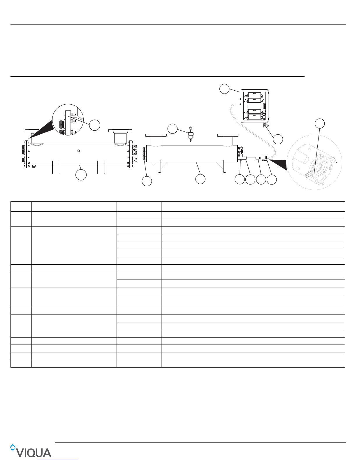
Figure 1 System Components
Item Descriptio n Part Number UV Systems
1 Controller
Replacement power cords for Hi-Flo
2
ICE Controller (sold separately)
3 Retaining nut assembly - Used on all Models
4 Lamp Harness
Hard glass, coated CIRCLINE-HO UV
5
lamps for long, consistent life (9000
hours)
6 O-ring 410867 Used on all Models
214 fused quartz sleeves with fire
7
polished ends
8 Chamber - -
9 Retaining nut RN-001 Used on all Models
10 Sensor 254NM-HF SHFM-140; SHFM-140/2; SHFM-180; SHFM-180/2; SHFM-290, SHFM-290/2
11 O-ring #2-369 EPDM 410631 SHF-290, SHF290/2, SHFM-290, SHFM-290/2
BA-ICE-HF SHF series, SHFM series
BA-ICE-M-HF SHFM series
260223R-001 NORTH AMERICAN (NEMA 5-15P), 3-PRONG GROUNDED
260223R-002 CONTINENTAL EUROPEAN (CEE 7/7) 2-PIN WITH GROUND, “SCHUKO”
260223R-003 AUSTRALIAN VERSION (AS 3112) 3-PRONG GROUNDED
260223R-004 UK VERSION (BS 1363) 3-PRONG
260193-R NO CONNECTOR, 3-WIRE, BARE LEADS
260227-R SHFM-140, SHFM-140/2, SHFM-180, SHFM-180/2
270278-R SHFM-290, SHFM-290/2
S740RL-4C SHF-140, SHF-140/2, SHFM-140, SHFM-140/2
S950RL-4C
QS-012 SHF-140, SHF-140/2, SHFM-140, SHFM-140/2
QS-180 SHF-180, SHF-180/2, SHFM-180, SHFM-180/2
QSO-950 SHF-290, SHF290/2, SHFM-290, SHFM-290/2
SHF-180, SHF-180/2, SHFM-180, SHFM-180/2; SHF-290, SHF290/2, SHFM-290,
SHFM-290/2
GROUNDED (5 AMP FUSE)
5

Installation of UV Disinfection System
Section 3 Installation of UV Disinfection System
CAUTION
Electronic controller must be connected to a Ground Fault Protected Circuit (GFCI) receptacle and the lamp connector ground wire must be connected
to the stainless steel chamber.
Before installing the system,
• Connecting pipes to the UV system should be supported, to avoid any undue strain on the UV chamber.
Note: The UV system should not bear any load of the attached piping.
• Avoid vibration from close proximity to heavy equipment or from erratic pumps (Vibrations from other equipment and/or
water hammer can cause damage to UV lamps within the UV chamber).
• Allow sufficient service access clearance for the unit. Also, when preparing the site for inst allation, allow for valves, drain
and bypass as part of your plumbing circuit.
The disinfection system is designed to be mounted horizontally within the main plumbing lines.
• The enclosure should be mounted either above or beside the reactor chamber. Never mount vertically with AC
connector at top of controller to prevent moisture from running down cordage and causing a potential fire hazard. Drip
loops in all cordage connected to controller is highly recommended.
• The complete water system, including any pressure or hot water tanks, must be sterilized before start up by flushing with
chlorine (household bleach) to destroy any residual contamination. Refer to Section 3.1.
• For safety purposes, the disinfection system must be connected to a GFCI.
• The disinfection system is intended for indoor use only . Do no t install disinfection system where it may be exposed to the
weather.
• A 5 Micron filtration must precede the disinfection system. Ideally, the disinfection system should be the last treatment
the water receives before consumption.
Procedure:
1. Figure 2 shows the installation of a typical disinfection system and the related components that may be used for the
installation. The use of a by-pass assembly is recommended in case the system requires “off-line” maintenance. In this
case, note the system requires supplementary disinfection for the distribution system if any water is used during by-pass
condition. In addition, during by-pass, the water will NOT be disinfected and a “DO NOT CONSUME THE WATER” tag
should be physically installed on the by-pass assembly until such time as the system is sanitized and returned to
service. For more information, refer to our disinfection procedure, Section 3.1. If the water is to be consumed while the
system is off-line, the water must be boiled for two minutes prior to consumption.
LAMP 1
LAMP 2
LAMP 3
LAMP 4
Figure 2 Disinfection System
2. Select a suitable location for the disinfection system and its related components. As it is recommended to install a GFCI,
make sure that this is taken into consideration prior to any installation. The system must be installed horizont ally, refer to
Figure 2. When selecting a mounting location, you must leave enough space to allow for the removal of the UV lamps
and/or quartz sleeves (typically leave a space equal to the size of the reactor chamber itself).
Note: Installation drawings show monitored system with UV sensor for representation purpose only.
6
 Loading...