

Viqua H, K, H Plus, K Plus, PRO10 Owner's Manual
...
425 Clair Rd. W, Guelph, Ontario, Canada N1L 1R1
t. (+1) 519.763.1032 • f. (+1) 800.265.7246 (US and Canada only)
t. (+31) 73 747 0144 (Europe only) • f. (+1) 519.763.5069
e-mail: info@viqua.com
www.viqua.com
425 Clair Rd. W, Guelph, Ontario, Canada N1L 1R1
t. (+1) 519.763.1032 • f. (+1) 800.265.7246 (US et Canada seulement)
t. (+31) 73 747 0144 (Europe seulement) • f. (+1) 519.763.5069
Courriel : info@viqua.com
www.viqua.com
425 Clair Rd. W, Guelph, Ontario, Canadá N1L 1R1
t. (+1) 519.763.1032 • f. (+1) 800.265.7246 (solo EE. UU. y Canadá)
t. (+31) 73 747 0144 (solo Europa) • f. (+1) 519.763.5069
correo electrónico: info@viqua.com
www.viqua.com
425 Clair Rd. W, Guelph, Ontario, Canada N1L 1R1
t. (+1) 519.763.1032 • f. (+1) 800.265.7246 (US and Canada only)
t. (+31) 73 747 0144 (Europe only) • f. (+1) 519.763.5069
e-mail: info@viqua.com
www.viqua.com
Models:
H, K
Plus Models:
H Plus, K Plus
PRO Models:
PRO10, PRO20, PRO30, PRO50
Owner’s Manual
Powered by
System Tested and Certified by
NSF International against CSA
B483.1 and NSF/ANSI 55 for
Disinfection Performance, Class A
602936_RevU
2 59
Congratulations on the purchase of your ultraviolet (UV) water disinfection
system! This system uses the most advanced UV technology on the market and is
designed to provide you with years of trouble free operation with minimal maintenance
required to protect your drinking water from microbiological contaminants.
To ensure ongoing disinfection of your water, UV lamps need to be replaced annually
with VIQUA factory-supplied replacements. VIQUA lamps are the result of extensive
development resulting in a highly efficient disinfection platform with extremely stable UV
output over the entire 9000 hour lifetime. Its success has led to a proliferation of
non-genuine copies in the market.
The UV lamp is the heart of the disinfection system, and there should be no compromise
when it's time for a replacement.
Why should you insist on genuine factory supplied VIQUA replacement lamps?
• Use of widely available, non-genuine, replacement lamps has been shown to damage
the control module of VIQUA UV disinfection equipment.
• An increasing number of calls to VIQUA Technical Support are connected with
non-genuine lamps being used (unknowingly) as replacements.
• Damage arising from the use of non-genuine lamps poses a safety risk and is not
covered by equipment warranty.
• Unless the UV equipment is equipped with a UV sensor (monitor), it is not possible to
verify the UV (invisible) output of replacement lamps.
• Similar appearance to the original lamp and the presence of (visible) blue light does
not mean equivalent disinfection performance.
• VIQUA replacement lamps undergo rigorous performance testing and strict quality
control processes to ensure that the safety and performance certifications of the
original equipment are not compromised.
So, you can see that it's simply not worth the risk! Insist on genuine VIQUA replacement
lamps.
Garantía del fabricante
Sección 8 Garantía del fabricante
Nuestro compromiso
VIQUA se compromete a asegurar que su experiencia con nuestros productos y organización superen sus expectativas.
Hemos fabricado el sistema de desinfección UV según los más altos estándares y lo valoramos como cliente. Si necesitara
soporte técnico o tiene preguntas acerca de su sistema, póngase en contacto con nuestro equipo de soporte técnico en el
1.800.265.7246 o en technicalsupport@viqua.com. Estaremos encantados de ayudarle. Esperamos que disfrute de las
ventajas que ofrece un agua potable limpia y segura después de la instalación del sistema de desinfección VIQUA.
Cómo realizar una reclamación bajo garantía
Nota: Para maximizar el rendimiento de desinfección y la fiabilidad de su producto VIQUA, el sistema se debe
dimensionar, instalar y mantener adecuadamente. En el manual del propietario encontrará información de utilidad
sobre los parámetros de calidad del agua necesarios y los requisitos de mantenimiento.
En el caso de que se necesitara una reparación o reposición de piezas cubiertas bajo esta garantía, el proceso lo
gestionará el distribuidor. Si no está seguro de si un problema o fallo del sistema está cubierto por la garantía, póngase en
contacto con nuestro equipo de soporte técnico en el 1.800.265.7246 o por correo electrónico en la dirección
technicalsupport@viqua.com. Nuestro técnicos completamente formados le ayudarán a resolver el problema e identificar
una solución. Tenga a mano el número de modelo (tipo de sistema), la fecha de compra, el nombre del distribuidor al que
adquirió el producto VIQUA ("distribuidor de origen") y una descripción del problema que está experimentando. Para
establecer la prueba de compra al realizar una reclamación bajo garantía, necesitará su factura original, o bien deberá
haber completado y enviado su tarjeta de registro de producto por correo postal o en línea.
Cobertura específica de la garantía
La cobertura de la garantía es específica de la gama de productos de VIQUA. La cobertura de la garantía está sujeta a las
condiciones y limitaciones establecidas en la sección "Condiciones y limitaciones generales".
Garantía limitada de diez años para la cámara UV de VIQUA
VIQUA garantiza que la cámara UV del producto VIQUA estará libre de defectos de material y mano de obra durante un
período de diez (10) años desde la fecha de compra. Durante este período, VIQUA reparará o reemplazará, a su criterio,
toda cámara UV VIQUA defectuosa. Devuelva la pieza defectuosa a su distribuidor, quién procesará su reclamación.
Garantía limitada de cinco años para los componentes eléctricos y de hardware
VIQUA garantiza que los componentes eléctricos (controlador) y de hardware estarán libres de defectos de material
y mano de obra durante un período de cinco (5) años desde la fecha de compra. Durante este período, VIQUA reparará
o reemplazará, a su criterio, toda pieza defectuosa cubierta por la garantía. Devuelva la pieza defectuosa a su distribuidor,
quién procesará su reclamación.
Garantía limitada de un año para lámparas UV, vainas tubulares y sensores UV
VIQUA garantiza que las lámparas UV, las vainas tubulares y los sensores UV estarán libres de defectos de material
y mano de obra durante un período de un (1) año desde la fecha de compra. Durante este período, VIQUA reparará
o reemplazará, a su criterio, toda pieza defectuosa cubierta por la garantía. Su distribuidor procesará su reclamación
y ofrecerá consejos sobre si el artículo defectuoso se debe devolver para realizar un análisis de fallos.
Nota: Utilice únicamente lámparas y vainas tubulares de reposición VIQUA originales en el sistema. El incumplimiento de
este requisito podría poner en riesgo el rendimiento de la desinfección y afectar a la cobertura de la garantía.
Condiciones y limitaciones generales
Ninguna de las garantías anteriores cubre los daños provocados por el uso o mantenimiento inadecuados, accidentes,
actos de la naturaleza o arañazos e imperfecciones menores que no afectan materialmente el funcionamiento del
producto. Las garantías tampoco cubren los productos que no se han instalado según las instrucciones del manual del
propietario correspondiente.
Las piezas reparadas o reemplazadas según estas garantías serán cubiertas bajo garantía hasta el final del período de
garantía aplicable a la pieza original.
Las garantías anteriores no incluyen el coste de envío y manipulación de los artículos devueltos. Las garantías limitadas
que se describen anteriormente son las únicas garantías aplicables a la gama de productos VIQUA. En estas garantías
limitadas se describe el único recurso para todas las reclamaciones basadas en un fallo o defecto de cualquiera de estos
productos, ya sea que la reclamación se base en contrato, agravio (incluida la negligencia), responsabilidad estricta u otro.
Estas garantías reemplazan a todas las demás garantías escritas, orales, implícitas o reglamentari as. No corresponde, sin
limitación, ninguna garantía de comerciabilidad o aptitud para un propósito particular a ninguno de estos productos.
VIQUA no asume ninguna responsabilidad por lesiones o daños a la propiedad causados por el uso o el mal uso de
cualquiera de los productos mencionados anteriormente. VIQUA no será de ningún modo responsable de los daños
especiales, incidentales, indirectos o consecuentes. La responsabilidad de VIQUA se limitará, en todos los casos, a la
reparación o reposición del producto o la pieza defectuosa y esta responsabilidad finalizará al finalizar el período de
garantía aplicable.
Safety Information
58 3
Section 1 Safety Information
Please read this entire manual before operating this equipment. Pay attention to all danger , warning, an d caution statements
in this manual. Failure to do so could result in serious personal injury or damage to the equipment.
Make sure that the protection provided by this equipment is not impaired. DO NOT use or install this equipment in any
manner other than that specified in the installation manual.
1.1 Potential Hazards:
Read all labels and tags attached to the system. Personal injury or damage to the system could occur if not observed.
1.2 Safety Precautions:
Waste electrical and electronic equipment (WEEE). This symbol
indicates that you should not discard wasted electrical or electronic
equipment (WEEE) in the trash. For proper disposal, contact your
local recycling/reuse or hazardous waste center.
This symbol indicates not to store any combustible or flammable
material close to the system.
This symbol indicates there is Mercury present.
This symbol indicates that the contents of the transport package are
fragile and the package should be handled with care.
This is the safety alert symbol. Obey all safety messages that follow
this symbol to avoid potential injury. When on the equipment, refer to
the Operational and Maintenance manual for additional safety
This symbol indicates safety glasses with side protection is required
for protection against UV exposure.
This symbol indicates a risk of electrical shock and/or electrocution
exists.
This symbol indicates gloves must be worn.
This symbol indicates the marked equipment may contain a
component that can eject forcibly. Obey all procedures to safely
depressurize.
This symbol indicates safety boots must be worn.
This symbol indicates the system is under pressure.
This symbol indicates the operator must read all available
documentation to perform required procedures.
This symbol indicates there is a potential UV hazard. Proper
protection must be worn.
This symbol indicates the plumber must use copper piping.
This symbol indicates the marked item could be hot and should not
be touched without care.
This symbol indicates that the system should only be connected to a
properly grounded, grounding-type controller receptacle that is
protected by a Ground Fault Circuit Interrupter (GFCI).
This symbol indicates there is a potential for VERY hot water when
flow is started.
Warning: This product may contain chemicals known to the State of California to cause cancer and birth defects or other reproductive harm.
DANGER
Failure to follow these instructions will result in serious injury or death.
• Electric Shock: To avoid possible electric shock, special care should be taken since water is present near the electrical equipment. Unless a
situation is encountered that is explicitly addressed by the provided maintenance and troubleshooting sections, DO NOT attempt repairs yourself,
refer to an authorized service facility.
• GROUNDING: This product must be grounded. If it should malfunction or breakdown, grounding provides a path of least resistance for electric
current to reduce the risk of electrical shock. This system is equipped with a cord having an equipment-grounding conductor and a grounding plug.
The plug must be plugged into an appropriate outlet that is properly installed and grounded in accordance with all local codes and ordinances.
Improper connection of the equipment-grounding conductor can result in a risk of electrocution. Check with a qualified electrician or service
personnel if you are in doubt as to whether the outlet is properly grounded. DO NOT modify the plug provided with this system – if it does not fit in
the outlet, have a proper outlet installed by a qualified electrician. DO NOT use any type of adapter with this system.
• GROUND FAULT CIRCUIT INTERRUPTER PROTECTION: To comply with the National Electrical Code (NFPA 70) and to provide additional
protection from the risk of electric shock, this system should only be connected to a properly grounded, grounding-type controller receptacle that is
protected by a Ground Fault Circuit Interrupter (GFCI). Inspect operation of GFCI as per manufacturer’s suggested maintenance schedule.
• DO NOT operate the disinfection system if it has a damaged cord or plug, if it is malfunctioning or if it has been dropped or damaged in any
manner.
• DO NOT use this disinfection system for other than intended use (potable water applications). The use of attachments not recommended or sold by
the manufacturer / distributor may cause an unsafe condition.
• DO NOT install this disinfection system where it will be exposed to the weather or to temperatures below freezing.
• DO NOT store this disinfection system where it will be exposed to the weather.
• DO NOT store this disinfection system where it will be exposed to temperatures below freezing unless all water has been drained from it and the
water supply has been disconnected.
Hg
UV
Cu
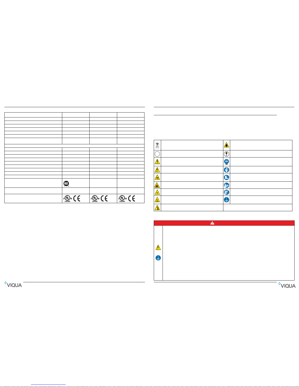
Especificaciones
Serie PRO Serie Plus Serie Basic
Sensor Sí Sí No
Ventilador CoolTouch Sí Sí Sí
Boquilla de flujo dinámica Sí (excepto PRO50) No No
Puertos de comunicación (dos, RJ45) Sí Sí Sí
Paquete de control COMMcenter Opcional Opcional Opcional
Válvula de solenoide Opcional Opcional Opcional
Sensor de medidor de flujo
(Solo modelos PRO10, 20, 30)
Sí No No
Controles
Botón de silencio de alarma sonora Sí Sí Sí
Botón de lámpara nueva Sí Sí Sí
Indicador de antigüedad de la lámpara Sí Sí Sí
Indicador de funcionamiento de la lámpara Sí Sí Sí
Indicador de funcionamiento del controlador Sí Sí Sí
Indicador de funcionamiento del solenoide Sí Sí Sí
Indicador de funcionamiento del ventilador Sí Sí Sí
Indicador de lectura de sensor Sí Sí No
Certificación NSF/ANSI
(Solo modelos PRO10, 20, 30)
Estándar 55
Clase A
No No
USEPA UVDGM 2006
(Solo modelo PRO50)
Sí No No
Otras certificaciones

Safety Information
4 57
1.3 Water Chemistry
Water quality is extremely important for the optimum performance of your UV system. The following levels are
recommended for installation:
* Where total hardness is less than 7 gpg, the UV unit should operate efficiently provided the quartz sleeve is cleaned
periodically. If total hardness exceeds 7 gpg, the water should be softened. If your water chemistry contains levels in excess
of those mentioned above, proper pre-treatment is recommended to correct these water problems prior to the installation of
your UV disinfection system. These water quality parameters can be tested by your local dealer, or by most private analytical
laboratories. Proper pre-treatment is essential for the UV disinfection system to operate as intended.
WAR NI NG
During extended periods of no water flow, the water in your chamber can become very hot (Approx. 60 °C) and potentially lead to scalding. It is
recommended to run your water until this hot water has been purged from your chamber. Do not allow water to contact your skin during this time. To
eliminate this condition, a temperature management valve can be installed at the outlet of your UV system.
CAUTION
Failure to follow these instructions could result in minor or moderate injury.
• Carefully examine the disinfection system after installation. It should not be plugged in if there is water on parts not intended to be wet such as, the
controller or lamp connector.
• Due to thermal expansion concerns and potential material degradation due to UV exposure, it is recommended to use metal fittings and at least 10"
of copper pipe on the outlet of your UV chamber.
NOTICE
• The UV lamp inside the disinfection system is rated at an effective life of approximately 9000 hours. To ensure continuous protection, replace the
UV lamp annually.
• The UV system is not to be used or played with by children. Persons with reduced physical, sensory or mental capabilities, or lack of experience
and knowledge, are also not to handle the UV system unless they have been given supervision or instruction.
• EXTENSION CORDS: If an extension cord is necessary, use only 3-wire extension cords that have 3-prong grounding-type plugs and 3-pole cord
connectors that accept the plug from this system. Use only extension cords that are intended for outdoor use. Use only extension cords having an
electrical rating not less than the rating of the system. A cord rated for less amperes or watts than this system rating may overheat. Exercise caution
when arranging the cord so that it will not be tripped over or pulled. DO NOT use damaged extension cords. Examine extension cord before using
and replace if damaged. DO NOT abuse extension cord. Keep extension cord away from heat and sharp edges. Always disconnect the extension
cord from the receptacle before disconnecting this system from the extension cord. Never yank cord to pull plug from outlet. Always grasp the plug
and pull to disconnect.
• SYSTEM PROTECTION: To protect your Controller, a UL1449 certified (or equivalent) transient voltage surge suppressor is strongly
recommended.
• The UV lamp in this system conforms to the applicable provisions of the Code of Federal Regulations (CFR) requirements including, Title 21,
Chapter 1, Subchapter J, Radiological Health.
• Read and understand the Owner’s Manual before operating and performing any maintenance on this equipment.
Water Quality and Minerals Level
Iron < 0.3 ppm (0.3 mg/L)
Hardness* < 7 gpg (120 mg/L)
Turbidity < 1 NTU
Manganese < 0.05 ppm (0.05 mg/L)
Tannins < 0.1 ppm (0.1 mg/L)
UV Transmittance > 75% (call factory for recommendations on applications where UVT < 75%)
Especificaciones
1. En algunos casos, se pueden crear flujos de corto plazo del agua de transmisión de rayos ultravioletas bajos (TUV)
después y durante el ciclo de regeneración de un ablandador de agua, lo que provoca la activación de una alarma del
sensor. La limpieza del sistema UV alivia esta condición, hasta que el ablandador pase por otro ciclo de regeneración.
A más largo plazo, se deben modificar los ajustes del ablandador. Para limpiar el sistema UV, desenchufe el sensor,
abra un grifo aguas abajo y deje que el agua corra durante dos (2) minutos. Desinfecte las líneas de agua según los
procedimientos que se indican en "Desinfección de las líneas de agua" de la sección sobre la instalación.
2. Consulte la sección sobre la limpieza de la vaina tubular y la reposición de la lámpara del manual del propietario.
3. Póngase en contacto con el distribuidor de tr atamientos de agua para consultar sobre la prueba de TUV del agua.
Sección 7 Especificaciones
General (todos los modelos)
Parámetros de funcionamiento
Presión máxima de funcionamiento 100 PSI (689 kPa)
Presión mínima de funcionamiento 15 PSI (103 kPa)
Temperatura máxima del aire ambiental 40 ºC (104 ºF)
Temperatura mínima del aire ambiental 0 ºC (32 ºF)
Humedad máxima 100 %
Dureza máxima 120 ppm (7 granos por 3,79 litros)
Nivel máximo de hierro 0,3 ppm
TUV mínimo 75 %*
Instalación SOLO vertical
Otros
Material de la cámara 316L SST
Ciclo de vida nominal de la lámpara hasta 2 años
* PRO50 cuenta con una calificación TUV mínima del 85 %
PRO10 PRO20 PRO30 PRO50 H, H Plus K, K Plus
Flujo nominal para NSF
Estándar 55, Clase A
10 gpm (38 lpm)
(2,2 m
3
/h)
20 gpm (76 lpm)
(4,5 m3/h)
30 gpm (113 lpm)
(6,8 m
3
/h)
---
Caudal a una dosis de
30 mJ/cm
2
al 95 % TUV
----
45 gpm (170 lpm)
(10 m
3
/h)
80 gpm (303 lpm)
(18 m
3
/h)
Caudal a una dosis de
40 mJ/cm
2
al 95 % TUV
----
37 gpm (140 lpm)
(8,4 m3/h)
60 gpm (226 lpm)
(13,6 m3/h)
Caudal para protocolo
USEPA UVDGM 2006
---
50 gpm (189 lpm)
(11,3 m3/h)
--
Eléctrico
Volta je
100 a 240 V
50 a 60 Hz
100 a 240 V
50 a 60 Hz
100 a 240 V
50 a 60 Hz
100 a 240 V
50 a 60 Hz
100 a 240 V
50 a 60 Hz
100 a 240 V
50 a 60 Hz
Corriente máxima 1,2 Amp 1,6 Amp 2,4 Amp 2,4 Amp 1,6 Amp 2,4 Amp
Consumo eléctrico máximo 120 vatios 160 vatios 230 vatios 230 vatios 160 vatios 230 vatios
Consumo eléctrico de la
lámpara
100 vatios 140 vatios 200 vatios 200 vatios 140 vatios 200 vatios
Tamaño del puerto
Entrada y salida
Combinación
NPT de 3,175 cm,
FNPT de 2,54 cm
Combinación
NPT de 3,175 cm,
FNPT de 2,54 cm
Combinación
NPT de 3,175 cm,
FNPT de 2,54 cm
MNPT de 5,08 cm
Combinación
NPT de 3,175 cm,
FNPT de 2,54 cm
MNPT de 5,08 cm
General Information
56 5
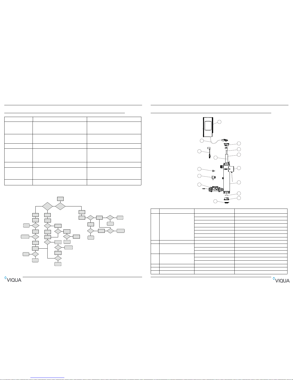
Section 2 General Information
Figure 1 System Components
Item Description Part Number UV Systems
1 Controller
650709-003 PRO10
650709-006 PRO20
650709-009 PRO30
660020-R PRO50
650709-005 H Plus
660019-R K Plus
650709-004 H
660018-R K
2 Top Bolt and Wireform 602916 & 602896 Used for all systems
3 Lamp
602854 PRO10
602855 PRO20, H Plus, H
602856 PRO30/50, K Plus, K
4Sleeve
602974 PRO10
602975 PRO20, H Plus, H
602976 PRO30/50, K Plus, K
5 CoolTouch Fan 650630 Used for all systems
6 Chamber - Used for all systems
7 O-ring 002233 Used for all systems
1
2
3
4
6
7
8
9
11
12
13
14
7
10
5
Solución de problemas
Sección 6 Solución de problemas
6.1 ALARMAS DE UV BAJO (solo las series PRO y Plus)
Síntoma Causa probable Posible solución
Sin potencia
Disparo del GFCI o contacto
Fusible del controlador quemado
Supresor de tensiones transitorias (TVSS) dañado
Controlador dañado
Restablecer el GFCI o contacto.
Reemplazar el fusible del controlador; consultar la sección sobre
la reposición de fusibles (consultar la Sección 4.3).
Reemplazar TVSS
Reemplazar el controlador y usar TVSS
Disparo repetido del GFCI
o contacto
La conexión entre la lámpara y el enchufe de la lámpara está
mojada
Cortocircuito en el conjunto eléctrico
Limpiar y secar las clavijas de la lámpara y el enchufe de la
lámpara; inspeccionar la unidad en búsqueda de fugas
o condensación
Reemplazar el controlador
Fuga en la entrada o salida Hay una fuga en los accesorios de canalización con rosca
Limpiar las roscas, volver a sellar con cinta Teflon y volver
a apretar
Fuga detectada en el área de la
cámara UV
Condensación de aire húmedo en la cámara fría (acumulación
lenta)
Junta tórica dañada, deteriorada o instalada de manera
incorrecta
Conjunto de lámpara/vaina tubular no instalado correctamente
(demasiado o insuficientemente apretado)
Controlar la humedad o cambiar la ubicación de la unidad
Inspeccionar la junta y reemplazar si está deteriorada
Asegurarse de que la tuerca se ha girado por completo
Alarma Consulte Sección 5.1.Consulte Sección 5.1.
El sistema funciona pero las
pruebas de agua indican
contaminación bacteriana
Los equipos instalados aguas abajo del sistema UV funcionan
como caldo de cultivo de agentes patógenos
Hay agentes patógenos que residen en las líneas de distribución
posteriores al tratamiento UV
Recontaminación de extremos sin salida de la canalización
Asegurarse de que UV sea el último equipo de tratamiento.
Asegurarse de que todas las líneas de distribución se hayan
desinfectado con cloro. Consulte Sección 3.2.
Quitar los extremos sin salida de la canalización y enjuagar con
cloro. Consulte Sección 3.2.
Indicador LED del sensor de
medidor de flujo en estado rojo
El sensor de detección de flujo no detecta el flujo
El sensor de detección de flujo no funciona
Aumentar el caudal a través del medidor
El medidor de flujo requiere mantenimiento o reposición
Figura 4 Alarmas de UV bajo (solo las series PRO y Plus)
Alarmas
de UV baja
Sí
Ámbar
Rojo
Verde
Ámbar
<75%
<75%
<75%
>75%
>75%
>75%
Verde
Verde
Verde
Rojo
Rojo
Verde
Verde
Verde
Verde
Verde
Verde
Rojo
Rojo
Rojo
Rojo
Rojo
Rojo
Rojo
No
Presencia de
medidor de flujo
Cortar
suministro
de agua
Limpiar
sistema
Ejecutar al
75 a 100 % del
flujo nominal
Restablecimiento
alimentación
Funcionamiento
normal
Funcionamiento
normal
LED de
sensor UV
LED de
sensor UV
LED de
sensor UV
Limpiar sistema
Limpiar
sistema
Ejecutar
sistema seco
LED de
sensor
LED de
sensor
LED de
sensor
Comprobar
TUV
UVT
Introducir
agua
Cambiar
sensor
Cambiar
lámpara
Cambiar
lámpara
Cambiar
sensor
LED de
sensor
LED de
sensor UV
Funcionamiento
normal
Funcionamiento
normal
Funcionamiento
normal
Solucionar
problema TUV
Solucionar
problema TUV
Limpiar
sistema
Flujo de agua
al 70 % del
flujo nominal
Comprobar
TUV
Comprobar
TUV
UVT
Solucionar
problema TUV
TUV
Cambiar
sensor
Cambiar
sensor
Ejecutar al
75 a 100 % del
flujo nominal
LED de
sensor
LED de
sensor
Cambiar
lámpara
Cambiar
lámpara
LED de sensor
UV parpadea LED
de medidor de flujo

General Information
6 55
2.1 Dimensions and Layout
8 Bottom bolt (includes screw) 603053 Used for all systems
9 Sleeve Removal Tool 602988 Used for all systems
10 Flow Meter Sensor (PRO models only)
410982R-10 PRO10
410982R-20 PRO20
410982R-30 PRO30
11 Sensor 650580 PRO and Plus models
12 Plug - Basic models
13 Power cord
602636 110V - Used for all systems
602637 220V - Used for all systems
14 Lamp cord - Used for all systems
Figure 2 System - Dimension and Layout
Item Description Function
1 Sample Valve Allows for sampling of raw water.
2 Shut-off Valve Allows for ease of maintenance of pre-treatment equipment.
3 Pre-Treatment
Pre-treatment allows the UV system to operate effectively. The water should meet
certain water quality parameters before entering UV System.
4 Bypass shut-off valve:
Bypass line and valve are optional. Intended to provide emergency water supply in the
event that the UV system is unavailable.
5 Shut-off valve Required to allow maintenance of UV system.
INLET
OUTLET
Clearance
for lamp
removal
72” (183cm
)
1”
A B
C
L
L
S
D
Ø
6
1162
3
5
4
13
11
12
7
15
9
8
10”
10
14
Funcionamiento
Sección 5 Funcionamiento
5.1 Panel de control
Figura 3 Panel de control
Botones y pantalla
Característica Descripción Función
A Silencio
Presionar para silenciar la alarma sonora.
Cuando la alarma se debe a la antigüedad de la lámpara, el botón Silencio silenciará la alarma sonora durante
7 días; esto se puede repetir un máximo de 4 veces. Luego, el botón se silenciará solo durante 24 horas.
Cuando la alarma se debe a algún otro problema, el botón Silenciar silenciará la alarma sonora durante 24 horas.
B Lámpara nueva
Después de instalar una lámpara nueva, mantener pulsado durante cinco segundos para restablecer el
temporizador de la lámpara en 365.
Luces indicadoras
LED Verde A maril lo Parpadea en rojo Rojo continuo
1
Válvula de solenoide abierta
(Si hay un solenoide)
No aplicable
Válvula de solenoide desconectada; volver
a conectar.
Bobina de solenoide dañada; reemplazar la
bobina (no todo el solenoide).
Válvula de solenoide inactiva
(cerrada) debido a un fallo de otro
componente, para garantizar la
seguridad del suministro de agua
2 Funcionamiento normal No aplicable
El conector de la lámpara no se ha
instalado correctamente. Asegurarse de
que la conexión a tierra del arnés de la
lámpara se ha insertado en el terminal de
conexión a tierra de la cámara.
Fallo del controlador; reemplazar el
controlador
Lámpara inactiva debido a un fallo
del controlador.
3 Funcionamiento normal No aplicable
Ventilador desconectado; volver a conectar.
El ventilador gira a una velocidad más
lenta que la necesaria; desenchufar el
sistema, limpiar las hojas con un hisopo
Ventilador dañado; reemplácelo.
No aplicable
4
Funcionamiento normal
Nota: El indicador parpadea
durante el calentamiento de la
lámpara
Advertencia: La lámpara se
deberá reemplazar
próximamente
Lámpara desconectada; desconectar la
alimentación, volver a conectar la lámpara
y conectar el controlador.
Fallo de la lámpara; reemplazar la lámpara
Lámpara inactiva debido a un fallo
del controlador
5
La dosis UV es adecuada y el
sensor funciona con
normalidad (solo para
modelos Plus)
La dosis UV está cerca de la
mínima requerida
Sensor desconectado; desenchufar el
sistema, volver a conectar el sensor
y volver a enchufar el sistema
Fallo del sensor
La dosis UV es inferior a la mínima
requerida, consultar la sección sobre la
alarma de UV bajo
Sensor inactivo debido a un fallo de
la lámpara o el controlador
6
El medidor de flujo funciona
con normalidad
Dosis UV de flujo alto
inadecuada, reducir el flujo
para conseguir niveles de
dosis más elevados (solo
PRO10, PRO20 y PRO30)
Fallo del sensor de medidor de flujo;
reparar o reemplazar el sensor
Dosis de UV de flujo bajo
inadecuada; se requiere servicio.
A
B
1
2
3
5
6
4

General Information
54 7
2.2 Pipe Lengths
The recommended minimum straight pipe lengths for the various piping configurations are:
Note: Flow Meter Sensor must be mounted in the following orientation with the LED facing up. Ensure all air is purged from
the piping and Flow Meter Sensor. All straight length to the Flow Meter Sensor must be 1.00" in diameter.
6 Solenoid valve
Allows water supply to be shut-off when proper disinfection cannot be assured.
Note: If the ground from your electrical panel is tied to your copper water lines, and you
are using a Plastic Body solenoid valve, installation of an approved ground strap is
required. This ground strap will maintain continuity between the lines that have been cut
to install the solenoid. Check your local electrical code for the correct clamp and cable
size.
7 Sample valve
Allows for sampling of water entering UV chamber; necessary in order to confirm water
being treated is of adequate quality.
8 Plug A stopper provided and installed on Basic models.
9 Sensor Monitors UV output to ensure proper dose (UV exposure) is being provided.
10 UV chamber Provides disinfection of the water. MUST BE INSTALLED VERTICALLY.
11 CoolTouch™ fan Removes excess heat from water in chamber during periods without water flow.
12 Sample valve
Allows for sampling of water immediately following UV treatment; necessary in order to
confirm proper operation of UV system.
13 Shut-off valve Allows maintenance of UV system.
14 Controller
Powers and controls the UV lamp and other devices. Provides human interface,
displaying information and allowing control inputs (such as muting the audible alarm).
15 Power source
Provides power to the controller. For safety reasons the outlet must be protected by a
Ground Fault Circuit Interrupter (GFCI).
Note: To protect the controller, a UL1449 certified (or equivalent) transient voltage surge
suppressor is required.
16 Flow Sensor
Monitors flow to provide real time dose (UV exposure) Flow Meter Sensor must be
installed in this orientation with the LED facing up. (PRO10, PRO20, PRO30 only)
Item L S (minimum) O A (maximum) B C D
PRO10 21.4” (55 cm) 12” (30 cm) 4” (10 cm) 72” (182 cm) 6.5” (16.5 cm) 13” (33 cm) 48” (122 cm)
PRO20, H Plus, H 31" (78 cm) 12” (30 cm) 4” (10 cm) 72” (182 cm) 6.5” (16.5 cm) 13” (33 cm) 48” (122 cm)
PRO30 41" (103 cm) 12” (30 cm) 4” (10 cm) 72” (182 cm) 6.5” (16.5 cm) 13” (33 cm) 48” (122 cm)
PRO50, K Plus, K 41" (103 cm) 12” (30 cm) 4” (10 cm) 72” (182 cm) 6.5” (16.5 cm) 13” (33 cm) 48” (122 cm)
Straight Flange 10" straight pipe
Reducing Flange 15" straight pipe 2 x 90 degree Elbows 25" straight pipe
2 x 90 degree Elbows 3 dimensions 40" straight pipe Pump 50" straight pipe
Mantenimiento
Nota: Tras reemplazar la lámpara UV o la vaina tubular, realizar el procedimiento de desinfección, consulte la Sección 3.2.
4.3 Reposición de fusibles
El sistema viene equipado de dos fusibles 3A de 250 V en funcionamiento. Para acceder a los fusib les, primero desenchufe
el sistema y desconecte el cable de alimentación del controlador. Para extraer el fusible, presione la pest aña en un lado con
un cuchillo u otra herramienta y tire de ella suavemente hacia afuera. Repita el proceso en el otro lado.
Procedimiento:
4.4 Mantenimiento del sensor de medidor de flujo
Inspeccione periódicamente el sensor de medidor de flujo para asegurarse de que no hay suciedad y que la rueda de
paletas gira libremente, sin resistencia.
Si la rueda de paletas no gira libremente o está suelta, deberá enviarse el sensor para ser reparado y calibrado. Para
garantizar un funcionamiento preciso del sistema, es recomendable enviar el sensor de medidor de flujo para calibrarlo
cada dos años.
13
13
• Vuelva a instalar la junta
tórica en la parte inferior de la
vaina tubular.
14
14
3
2
1
• Conecte el perno de la vaina
tubular en la parte inferior.
• Cuando haya finalizado el
servicio, realice los pasos que
aparecen en los requisitos
previos en orden inverso al
desmontaje.
1
• Desconecte el controlador del
sistema.
2
• Reemplace el fusible.

Installation
8 53
Section 3 Installation
3.1 Installing UV System
Prerequisites:
• Determine appropriate indoor location of the controller and chamber, refer to Section 2.1.
• Make sure that the controller is installed higher than the chamber and away from all water sources.
• Ensure adequate clearance above chamber to allow for removal of the lamp and sleeve.
• Make sure to turn off the main water supply.
• Make all necessary plumbing connections refer to Section 2.1.
Procedure:
CAUTION
Electronic controller must be connected to a Ground Fault Protected Circuit (GFCI) receptacle.
1
• Install the UV Chamber
vertically with the following
spacing on the wall using
screws.
• PRO10: 18.5"
• H, PRO20: 27.5"
• K, PRO30/50: 37.5"
Note: Ensure chamber is
installed with green arrows
pointing upwards.
2
• Connect Flow Meter Sensor
(PRO10,20,30 models only)
to chamber using 1¼” unions
supplied.
Note: LED must face up.
Ensure proper length of
straight pipe 1.0" Diameter at
inlet side of Flow Meter
Sensor and use a 1¼” to 1"
Reducing Coupler (not
supplied).
3
• Install the sensor to the UV
system (for PRO models
only).
Note: DO NOT use wrench to
4
2
1
• Connect the sleeve bolt at the
bottom of the sleeve
assembly. Ensure sleeve bolt
is rotated full 1/4 turn until
positive stop.
5
• Insert sleeve with arrow
pointing up.
Note: DO NOT rotate sleeve
and touch glass with bare
hands.
6
• Wet O-ring with water then
place over top end of sleeve.
7
2
1
• Connect the sleeve bolt to the
top of the sleeve assembly.
Ensure sleeve bolt is rotated
full 1/4 turn until positive stop.
8
1
2
• Remove the sleeve bolt at the
bottom of the sleeve
assembly.
Mantenimiento
Procedimiento:
1
2
1
• Extraiga el perno de la vaina
tubular de la parte superior
del conjunto de la vaina
tubular.
2
1
2
3
• Quite el tornillo del perno de
la vaina tubular.
• Extraiga el perno de la vaina
tubular en la parte inferior del
conjunto de vaina tubular.
3
• Inserte la herramienta de
extracción de la vaina tubular
en la parte inferior de la vaina
tubular.
4
• Levante la vaina tubular hasta
que se suelte.
• Coloque un cubo debajo de la
cámara UV, ya que saldrá
agua.
5
• Quite la vaina tubular.
6
• Quite la junta tórica de la
parte superior de la vaina
tubular.
• Quite la junta tórica de la parte
inferior de la cámara
(es posible que se caiga
durante el proceso de
extracción de la vaina tubular).
7
Mild
Acid
• Limpie la vaina tubular con un
trapo empapado en CLR,
vinagre u otro ácido blando y
luego aclárela con agua.
Nota: Si no es posible limpiar
la vaina tubular por completo
o si se raya o se quiebra,
reemplácela.
8
3
1
2
• Conecte el perno de la vaina
tubular en la parte inferior del
conjunto de vaina tubular.
9
• Vuelva a instalar la vaina
tubular con la flecha
orientada hacia arriba.
Nota: NO gire la vaina tubular
ni toque el cristal con las
manos sin protección.
1010
• Vuelva a instalar las nuevas
juntas tóricas lubricadas
sobre la parte superior de la
vaina tubular.
1111
2
1
• Conecte el perno de la vaina
tubular en la parte superior
del conjunto de vaina tubular.
1212
1
2
• Extraiga el perno de la vaina
tubular en la parte inferior del
conjunto de vaina tubular.
52 9
Note: After installing the UV lamp or sleeve perform the disinfection procedure, refer to Section 3.2.
3.2 Disinfection Procedure
UV disinfection is a physical disinfection process and does not add any potentially harmful chemicals to the water. As UV
does not provide a disinfection residual, it is imperative that the entire distribution system located after the UV be chemically
disinfected to ensure that the plumbing system is free from any bacteriological contaminants. The disinfection process must
be performed immediately after the UV unit is installed and repeated thereafter whenever the UV is shut down for service,
without power, or inoperative for any reason. The procedure for sanitizing the plumbing system is readily accomplished as
follows:
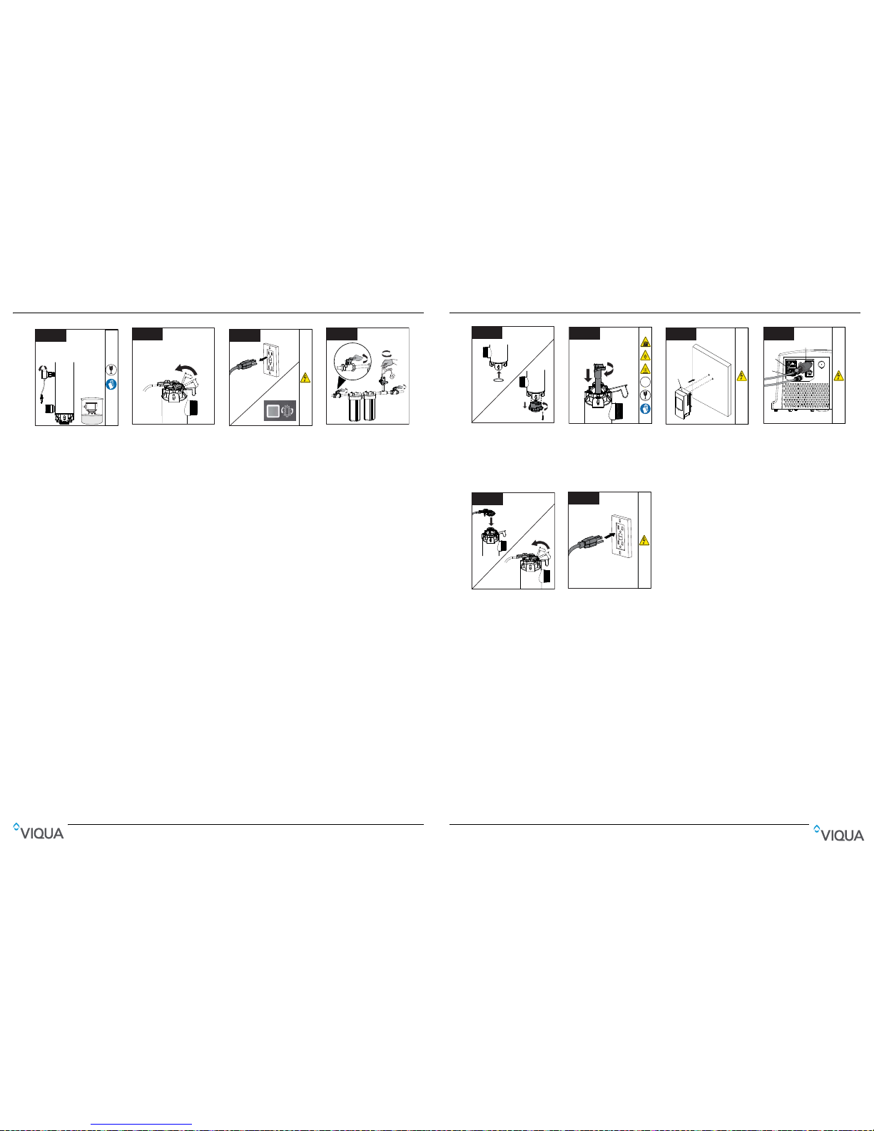
9
3
2
1
• Wet O-ring with water then
place over bottom end of
sleeve.
• Reconnect the sleeve bolt
and install screw.
1010
2
1
Hg
UV
• Install and rotate the lamp
into the sleeve assembly.
Ensure to rotate the lamp
completely.
Note: Do not touch glass with
bare hands.
1111
4¹⁄16“
(10.4cm)
• Install the controller unit to
the wall. Ensure that the
controller is installed higher
than the chamber and away
from all water sources.
1212
1
2
3
• Connect UV sensor into blue
jack (For PRO and Plus
models only).
• Connect Flow meter sensor
into green jack (For PRO10,
20, 30 only).
• Connect CoolTouch™ fan
into either receptacle.
1313
• Install lamp harness onto
chamber.
Note: Ensure lamp harness
ground is inserted into
chamber ground terminal
• Lock wire form into position.
1414
• Connect controller to power
outlet.
• Allow water flow to one faucet
or other water outlet, then
close the outlet and inspect
for leaks.
Note: Outlet must be
protected by a Ground Fault
Circuit Interrupter (GFCI).
Installation
Nota: Tras reemplazar la lámpara UV, realice el procedimiento de desinfección, consulte la Sección 3.2.
4.2 Limpieza y reposición de la vaina tubular
Nota: Los minerales del agua van formando lentamente una capa en la vaina tubular de la lámpara. Esta capa debe
retirarse porque reduce la cantidad de luz UV que llega al agua, reduciendo de este modo el rendimiento de la desinfección.
Si la vaina tubular no puede limpiarse, deberá reemplazarse por otra.
Requisitos previos:
• Cortar el suministro de agua y drenar todas las líneas.
• Quitar la lámpara UV. Consulte Sección 4.1.
9
Eliminador de
sarro comercial
1
2
• Extraiga el sensor UV de la
unidad.
• Sumerja el extremo del sensor
y límpielo con un hisopo.
• En el modelo básico, vaya al
paso 10.
1010
• Fije la forma de alambre en
su posición.
1111
• Restaure la energía.
• Mantenga pulsado el botón
"Lámpara nueva" durante
5 segundos, hasta oír un
pitido.
1212
• Active el suministro de agua.
Mantenimiento
 Loading...