

Page 1
520373-R_RevA
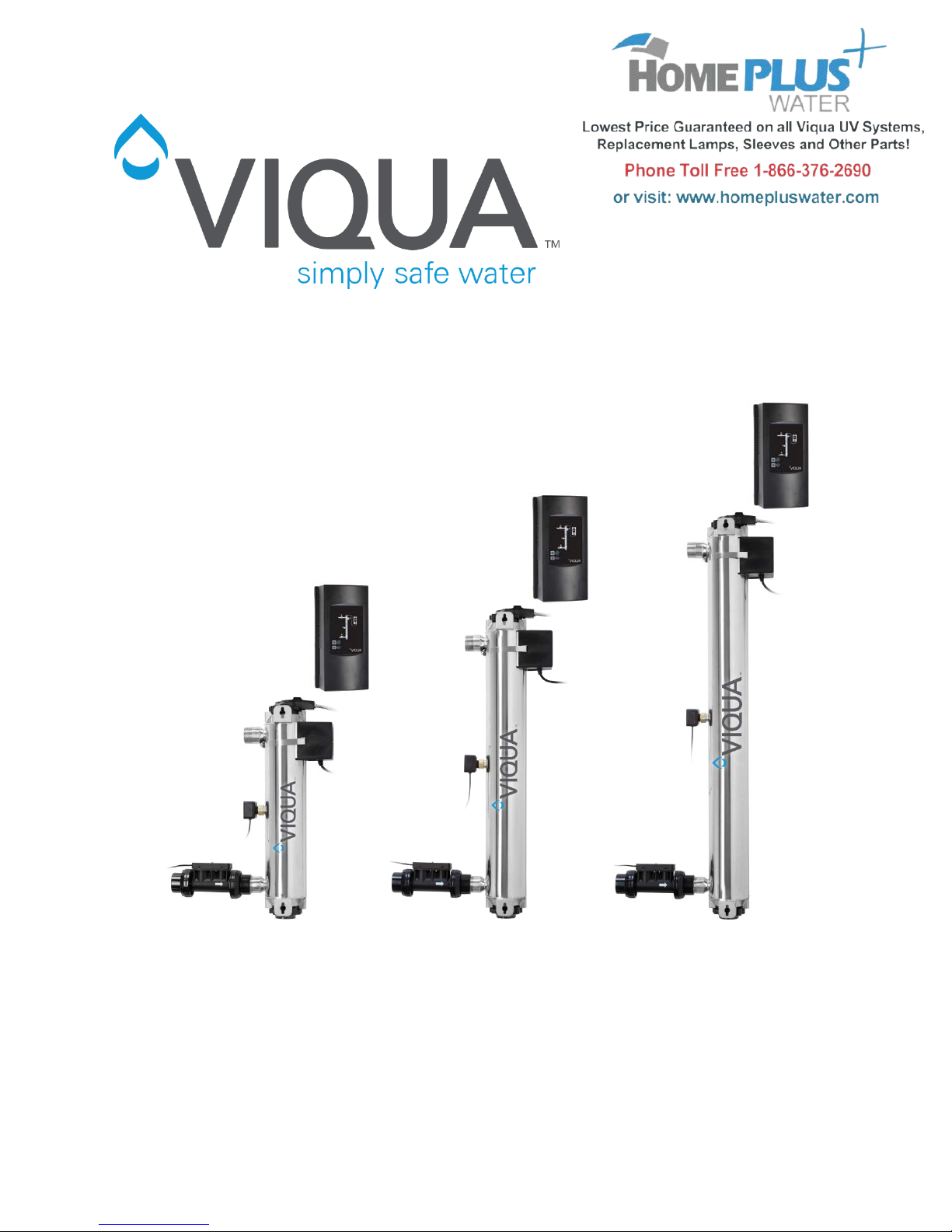
PRO Series
PRO10 PRO20 PRO30
Page 2

Table of Contents
Preface .............................................................................................................................ii
Contact Information ......................................................................................................ii
About VIQUA – a Trojan Technol og i es Busi ne s s .........................................................ii
Scope ...........................................................................................................................ii
1.0 Project & System Description ................................................................................ 1
1.1 Project Description ............................................................................................. 1
1.2 System Description ............................................................................................ 1
2.0 Product Drawings .................................................................................................. 2
2.1 Install Diagram ................................................................................................... 2
2.2 Exploded View ................................................................................................... 3
3.0 System Overview .................................................................................................. 5
3.1 Pressure Drop .................................................................................................... 5
3.2 Dose Curves ...................................................................................................... 5
3.3 Controller Interface ............................................................................................. 7
3.4 UV Lamp ............................................................................................................ 8
3.4.1 Mercury Discharge Lamp Spectral Output ................................................... 8
3.4.2 Degradation Chart ....................................................................................... 9
3.4.3 Temperature Profile ..................................................................................... 9
3.4.4 Quartz Sleeve ............................................................................................ 11
3.5 UV Sensor ........................................................................................................ 11
3.5.1 Sensor Response Curve............................................................................ 11
3.6 Flowmeter ........................................................................................................ 12
3.7 Product Features and Benefits ......................................................................... 12
3.7.1 Real-Time UV Dose Monitoring ................................................................. 12
3.7.2 LightWise™ Technology ............................................................................ 13
3.7.3 Adjustable Alarm Set Points ...................................................................... 14
3.8 Signals and Remote Capabilities ..................................................................... 14
3.8.1 COMMcenter™ .......................................................................................... 14
3.8.2 Dry Contacts .............................................................................................. 14
3.8.3 4-20 mA Interface ...................................................................................... 15
4.0 Certifications ........................................................................................................ 15
5.0 Warranty .............................................................................................................. 15
VIQUA Declaration ........................................................................................................ 17
i
Page 3

PREFACE
Contact Information
425 Clair Road West
Guelph, Ontario, Canada
N1L 1R1
Tel: 519-763-1032
Fax: 519-763-5069
[email protected]
www.viqua.com
About VIQUA – a Trojan Technologies Business
We believe clean water is an invaluable resource. That’s why, for more than a quarter of
a century, we have led the development of water treatment solutions using
environmentally friendly ultraviolet (UV) light. Today, VIQUA has the largest installed
base of UV systems in operation on the planet, and many of our innovations define the
industry standards for safeguarding our water from the damaging effects of microbial
contamination.
From offices and facilities in eight countries, the 800 employees of Trojan are united by
an unwavering commitment to deliver advanced water treatment solutions that make
water safety a reality worldwide.
VIQUA is an ISO9 001:2008 registered company specializing in the design, manufacture
and sale of ultraviolet systems for:
• household drinking water
• light commercial drinking water
• point-of-use treatment
• point-of-entry treatment
VIQUA has over 600,000 systems installed worldwide and VIQUA systems can be
found in almost every country in the world. Applications of VIQUA systems include rain
water harvesting, ground water treatment, disaster relief, humanitarian aid, medical
devices and bottled-water refill stations.
Scope
This document highli ghts th e feat ur es and specifications of the PRO10, PRO20, and
PRO30 systems. These PRO products are NSF Standard 55 Class A certified and are
ideal for regulated markets and light commercial applications.
ii
Page 4

Project Name
Guidelines
Maximum flow rate
10, 20, or 30 GPM
Design dose
40, 80, or 120 mJ/cm
2
Operating pressure
15 psi (103 kPa) - 125 psi (862 kPa)
Ambient air temp.
0°C (32°F) - 40°C (104°F)
Ambient water temp.
2°C (35.6°F) - 40°C (104°F)
Hardness
120 ppm (7 grains / gallon) max.*
Manganese content
0.05 ppm max.*
Iron content
0.3 ppm max.*
UVT
75% min.*
Model
PRO10
PRO20
PRO30
Quantity
Chamber
Material
316L SST
Dimensions
21.4” x 4” (55 x 10 cm)
31” x 4” (78 x 10 cm)
41” x 4” (103 x 10 cm)
Inlet & outlet ports
Combo 1-1/4" MNPT, 1" FNPT
UL Certified burst
pressure
Orientation
Vertical
Integrated flow
restrictor
Electrical
Power Supply
13” x 6.5” (33 x 16.5 cm)
Voltage
100 - 240 V AC
Frequency
50 - 60 Hz
Max. current
1.2 Amps
1.6 Amps
2.5 Amps
Max. power
consumption
Lamp power
100 Watts
140 Watts
200 Watts
Spare Parts
Quantity
Optional Accessories
Quantity
Lamps
COMMcenter™
Sleeves
Solenoid valve
UV sensors
4-20 mA Interface
Flowmeters
CoolTouch™ Fans
1.0 PROJECT & SYSTEM DESCRIPTION
1.1 Project Description
1.2 System Description
*after pretreatment
300 psi (2.067 MPa)
10 GPM (38 lpm) max. 20 GPM (76 lpm) max. 30 GPM (113 lpm) max.
120 Watts 160 Watts 230 Watts
1
Page 5
Item
L
S (min.)
Ø
A (max.)
B
C
D (max.)
2.0 PRODUCT DRAWINGS
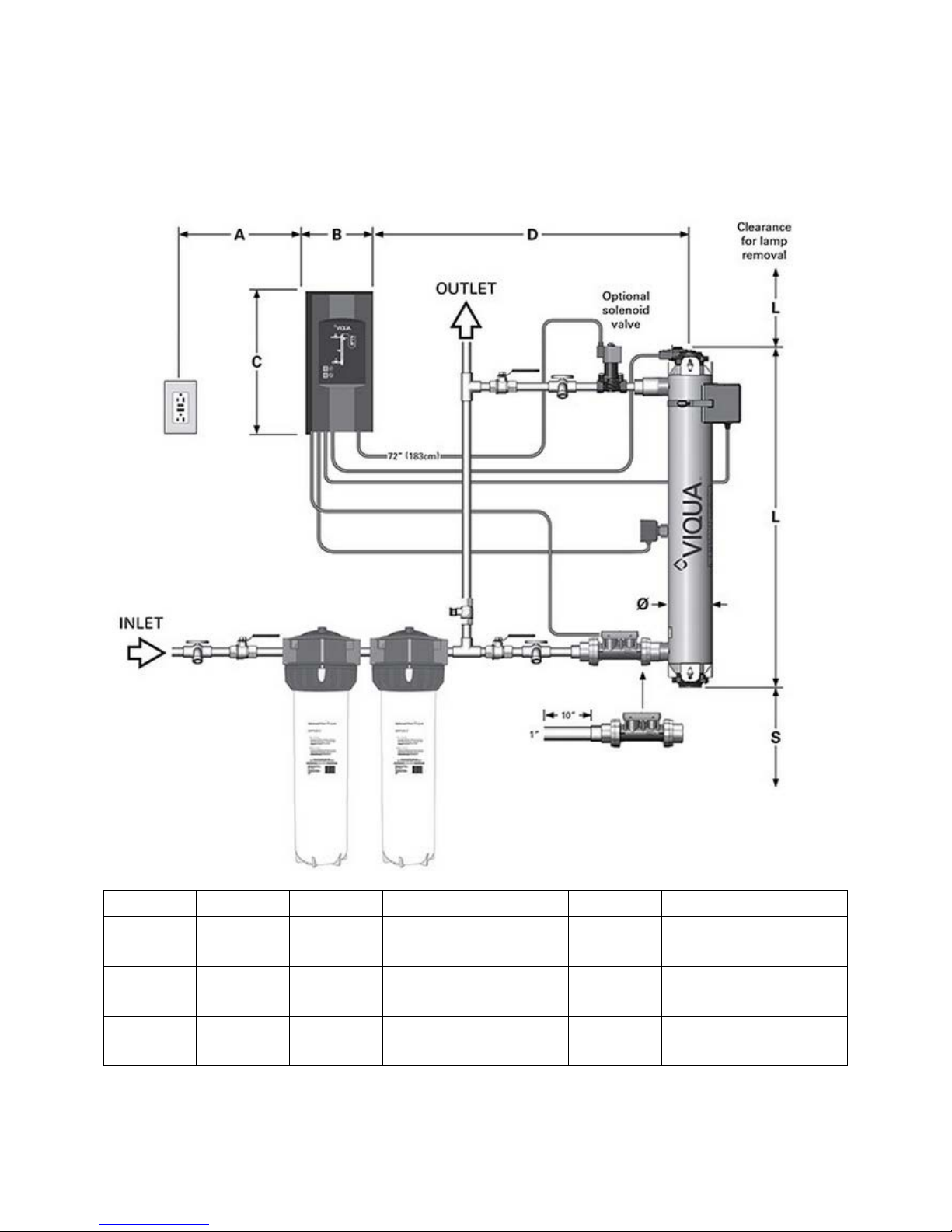
2.1 Install Diagram
PRO10
PRO20
PRO30
21.4”
(55 cm)
31”
(78 cm)
41”
(103 cm)
(30 cm)
(30 cm)
(30 cm)
12”
12”
12”
4”
(10 cm)
4”
(10 cm)
4”
(10 cm)
72”
(182 cm)
72”
(182 cm)
72”
(182 cm)
2
6.5”
(16.5 cm)
6.5”
(16.5 cm)
6.5”
(16.5 cm)
13”
(33 cm)
13”
(33 cm)
13”
(33 cm)
48”
(122 cm)
48”
(122 cm)
48”
(122 cm)
Page 6

47” max.
4 ⅛”
PRO10: 18 ½”
2.2 Mounting Diagram
PRO20: 27 ¾”
PRO30: 37 ½”
3
Page 7
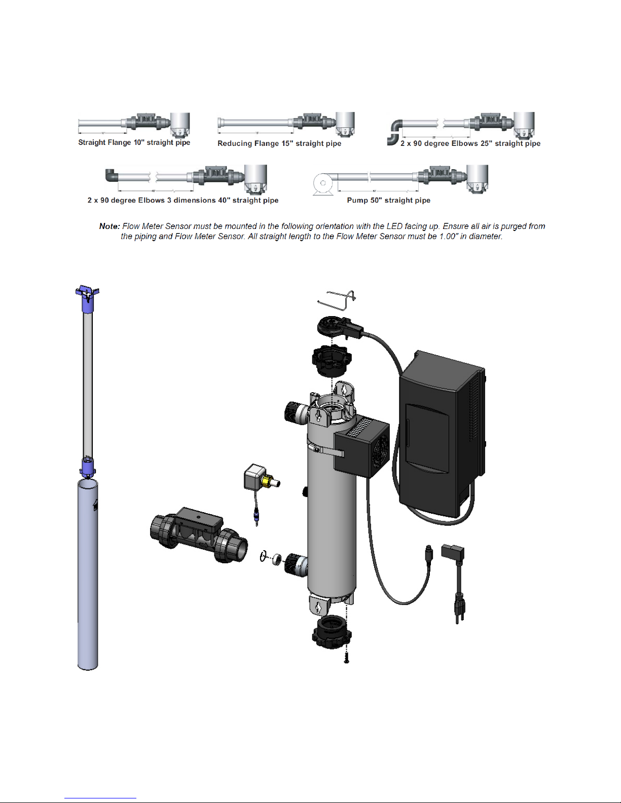
2.3 Flow Meter Installation Option
2.4 Exploded View
Refer to .pdf and .step files for engineering drawings and part numbers.
4
Page 8
Pressure Drop (psi)
3.0 SYSTEM OVERVIEW
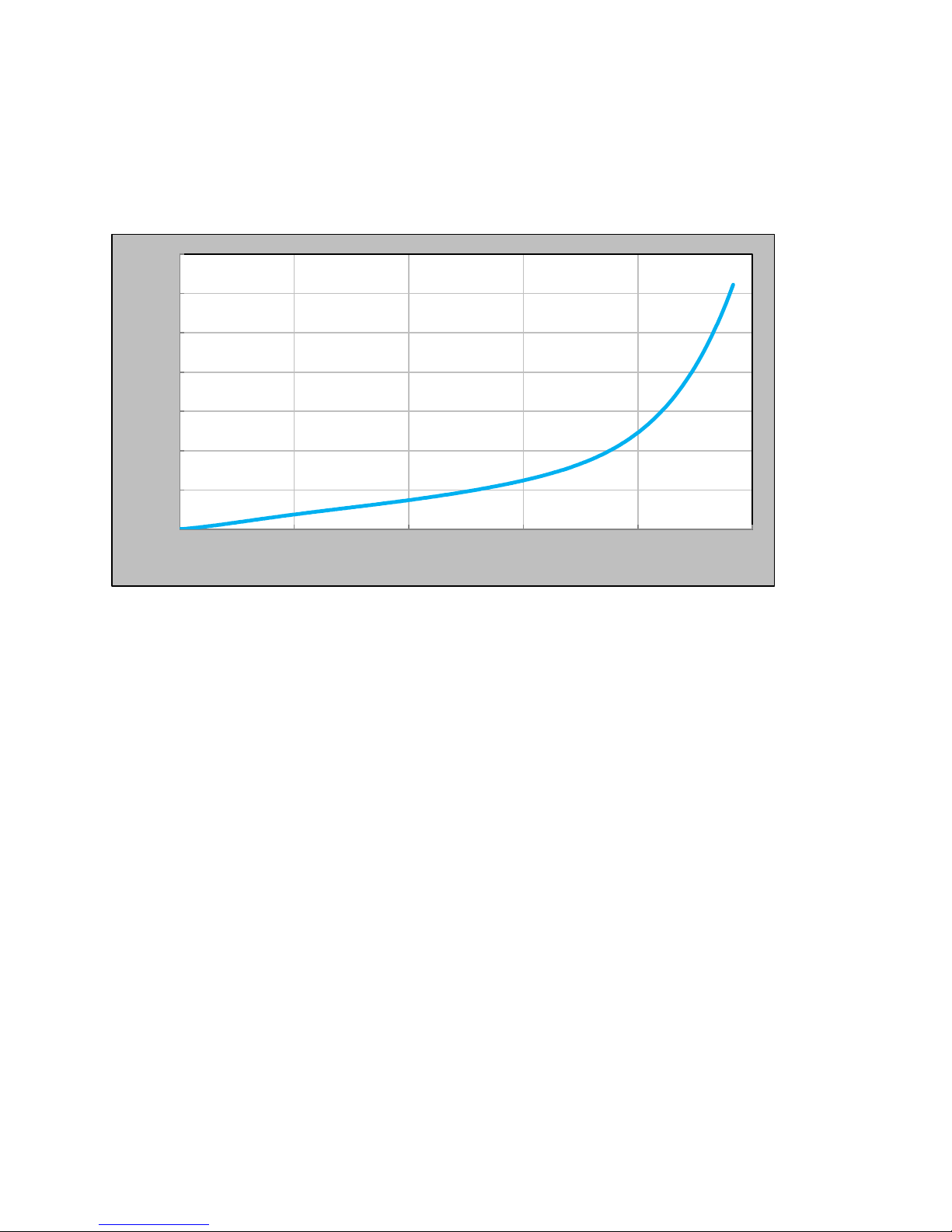
3.1 Pressure Drop
The pressure drop across the system is proportional to the flow through the system.
70
60
50
40
30
20
10
0
0 20 40 60 80 100
% of Rated System Flow
3.2 Dose Curves
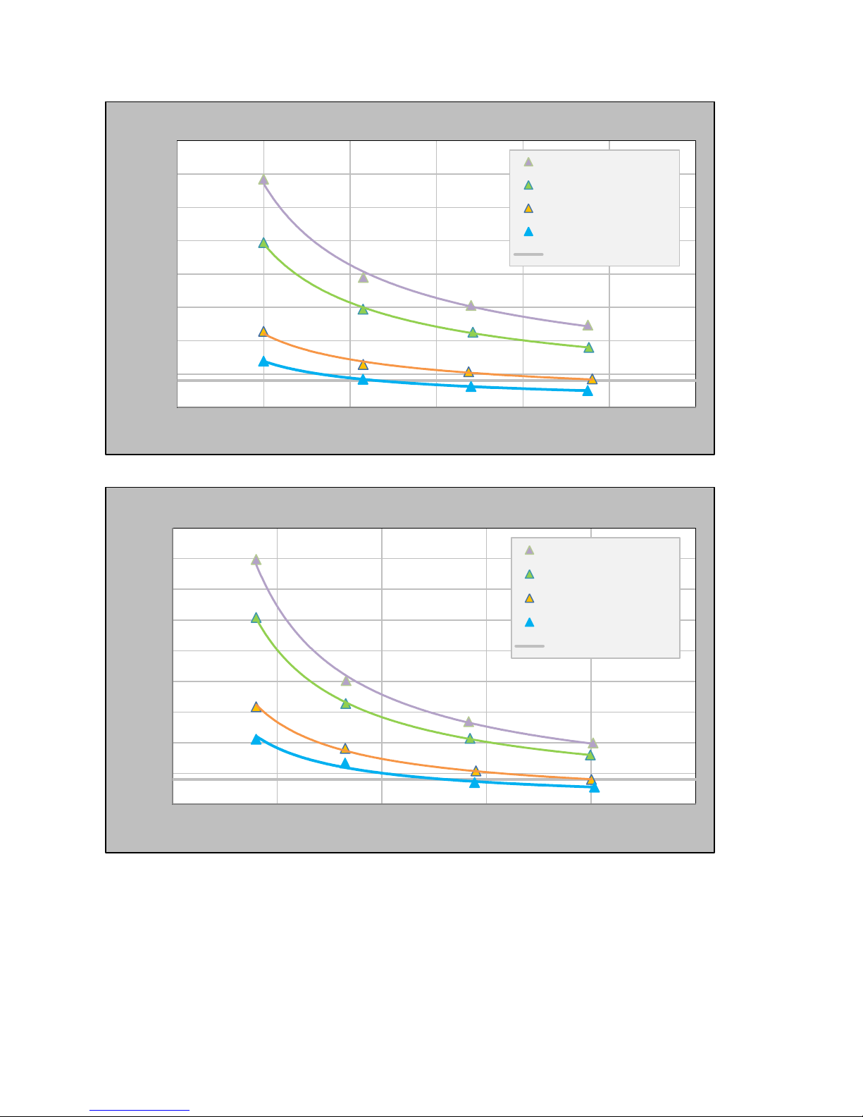
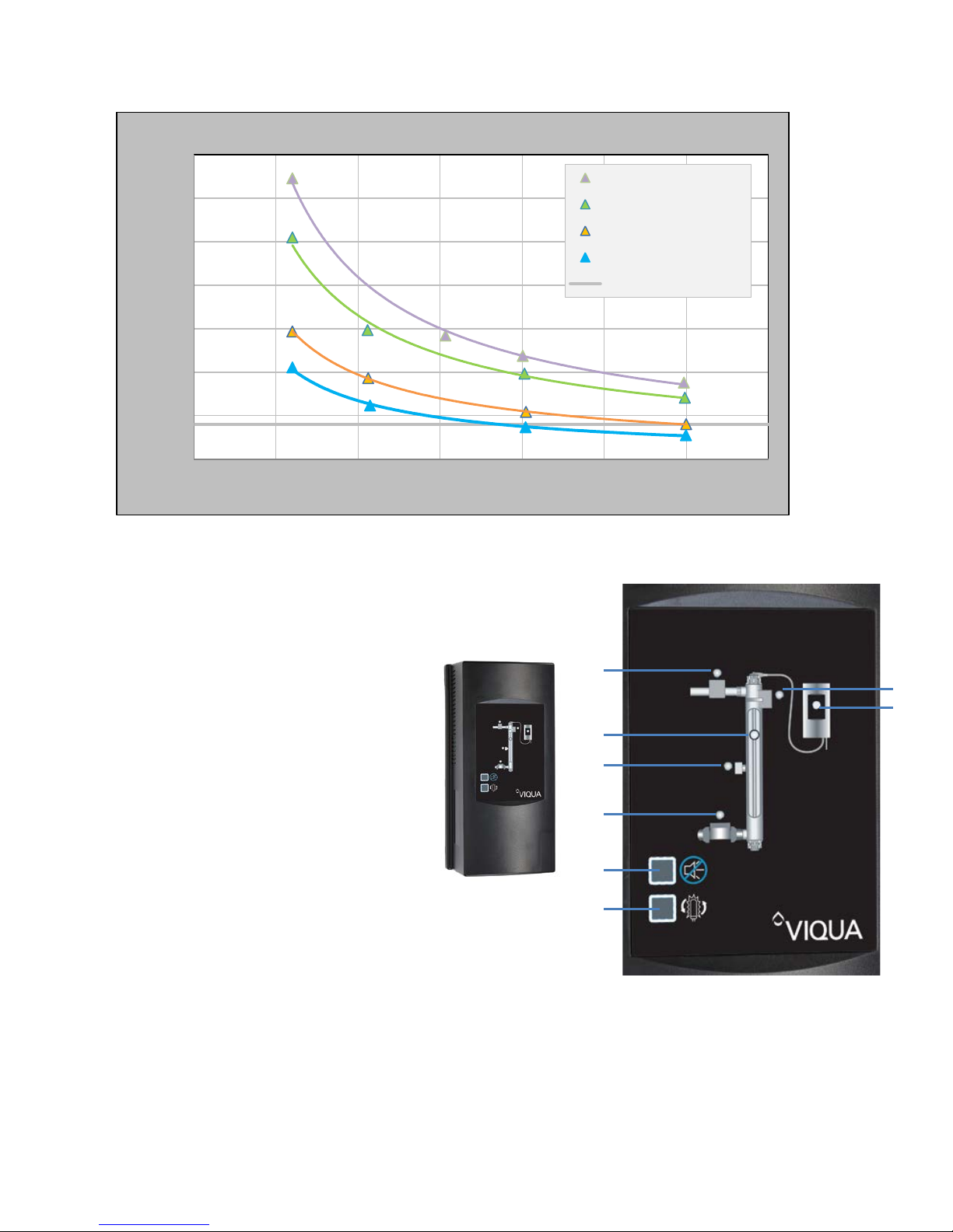
Flow rate, UVT, and required UV dose conditions dictate which sy s tem is appropr i ate
for a given location.
Dose values such as those in the following graphs are calculated based on set-points.
Set-point conditions are determined by third party verified bioassay testing completed in
compliance with the 2006 UV Disinfection Guidance Manual (UVDGM).
Each of the PRO systems has a unique flow restrictor to limit flow rates to 10, 20, and
30 GPM for the PRO10, PRO20, and PRO30 systems respectively. These restrictors
are found in the inlet port of the chamber and physically inhibit flow rates from
exceeding maximum design flow.
5
Page 9
Flow rate (gpm)
PRO10
400
95% UVT
85% UVT
65% UVT
55% UVT
NSF Alarm Set Point
2
)
Dose (RED) (mJ/cm
350
300
250
200
150
100
50
0
0 2 4 6 8 10 12
PRO20
450
95% UVT
85% UVT
65% UVT
55% UVT
NSF Alarm Set Point
2
400
350
)
300
250
200
150
Dose (RED) (mJ/cm
100
50
0
0 5 10 15 20 25
Flow rate (gpm)
6
Page 10
PRO30
3
2
9 8 4 6 7
5
350
95% UVT
2
)
300
250
85% UVT
65% UVT
55% UVT
200
150
100
Dose (RED) (mJ/cm
50
0
0 5 10 15 20 25 30 35
Flow rate (gpm)
NSF Alarm Set Point
3.3 Controller Interface
The controller is equipped with the following features:
1. Audible alarm
2. Audible alarm mute
3. Replacement lamp counter reset
4. Lamp operation indicator
5. Controller operation indicator
6. Solenoid valve operation indicator
7. Fan operation indicator
8. Sensor reading indicator
9. Flow meter operation indicator
Firmware in the controllers monitors flow rate and sensor input for set point conditions.
Controllers will enter audible and visual alarm if the sensor input is too low given the
measured flow rate. Set points depend on the Adjustable Alarm Set Points (sec. 3.7.3).
7
Page 11
Features
• Continuously monitors and controls the system.
• Communicates min or and maj or audibl e al ar ms w hen conditions fall outside the NSF
Standard 55 Class A prescribed operating range.
• Auto-ranging.
• Constant Current.
3.4 UV Lamp
3.4.1 Mercury Discharge Lamp Spectral Output
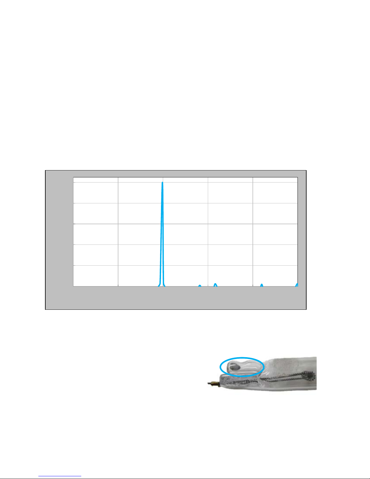
The lamp produces germicidal ultraviolet light (UV-C) at a wavelength of 253.7 nm. The
absence of a peak at 185 nm is significant because it means no harmful ozone will be
produced. VIQUA’s PRO system amalgam lamps have a mercury content of less than
15 mg (IMERC registered).
100
80
60
40
Spectral Irradiance (%)
20
0
155 205 255 305 355 405
Wavelength, λ (nm)
VIQUA’s amalgam lamps use a mercury amalgam matrix as opposed to mercury in its
pure liquid form. Therefore, the mercury is contained as a secure, solid segment.
Additionally, this segment is trapped in a compartment at the bottom of the lamp.
In the case of a broken lamp, this compartment
would contain the mercury. Even if this
compartment also broke open, the quartz sleeve
prevents the mercury from coming in contact
with water flowing through the chamber.
Features
• All electrical connections made at one end of the lamp.
• Lamp base features a di aboli c barr i er w hich prevents arcing between pins.
8
Page 12
253.7nm Output (%)
3.4.2 Degradation Chart
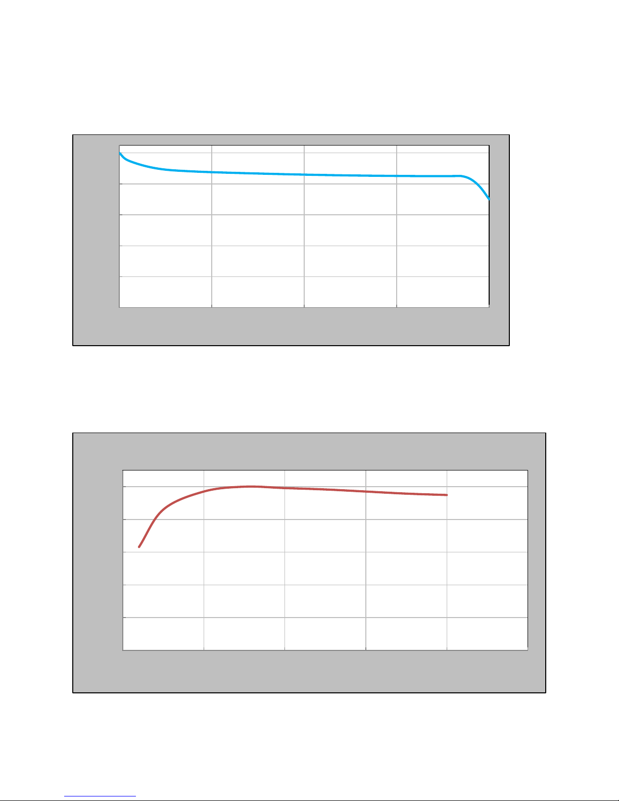
Amalgam lamps have a useful life of approximately 18,000 hours. They can provide
adequate disinfect ion for up to two years and then require replacement.
100
80
60
40
20
0
0 5000 10000 15000 20000
Burning Hours
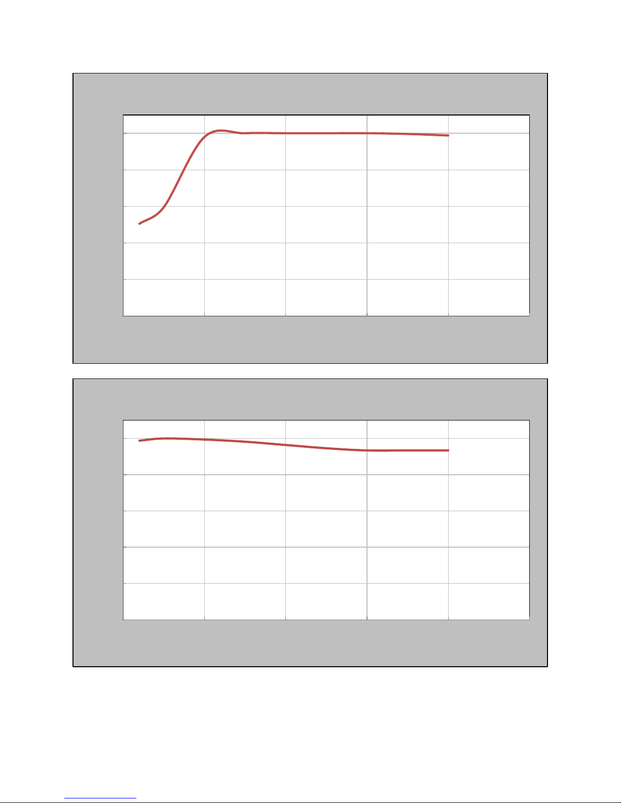
3.4.3 Temperature Profile
VIQUA’s lamps use a mercury amalgam mix to control the vapour pressure and
produce a more stable output than conventional standard output lamps.
Pro 10 Temperature Profile
100.0
90.0
80.0
70.0
60.0
% of Peak UV Intensity
50.0
0 10 20 30 40 50
Water Temperature (°C)
9
Page 13
% of Peak UV Intensity
100.0
90.0
80.0
70.0
60.0
50.0
Pro 20 Temperature Profile
0 10 20 30 40 50
100.0
90.0
80.0
70.0
60.0
% of Peak UV Intensity
50.0
Water Temperature (°C)
Pro 30 Temperature Profile
0 10 20 30 40 50
Water Temperature (°C)
10
Page 14
3.4.4 Quartz Sleeve
The UV lamp is enclosed by a quartz sleeve made of GE Type 214 or equivalent clear
fused silica quartz.
Mineral deposits will form on the quartz, which inhibit the amount of light that can reach
the water. The sleeve must be manu al ly cleaned on a regular basis using a mineral acid
such as a calcium, lime, and rust remover.
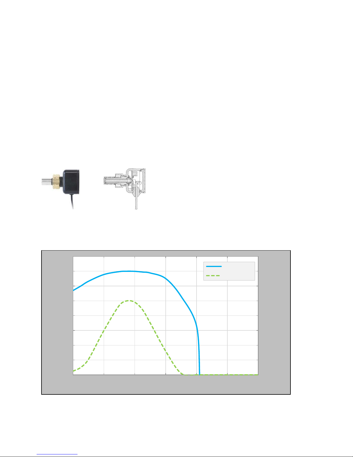
3.5 UV Sensor
Many factors influence a system’s level of UV disinfection. Some of these factors
include water quality (primarily UVT), lamp output, and quartz sleeve fouling. Rather
than base set-points on any one of these factors, alarm set-points are based on the
quantity of light that actually reaches the sensor. In this way, the UV sensor detects
when the water is no longer being purified properly as a result of change in any
influential factor. VIQUA’s UV sensors reliably detect low UV output and identify the
need for maintenance.
3.5.1 Sensor Response Curve
The sensor’s photodiode detects the emitted germicidal 253.7 nm wavelength.
1E+0
Logarithmic Spectral Response, S (A/W)
1E-1
1E-2
1E-3
1E-4
1E-5
1E-6
1E-7
1E-8
200 250 300 350 400 450 500
Wavelength, λ (nm)
Logarithmic
Linear
0.16
0.14
0.12
0.1
0.08
0.06
0.04
0.02
0
Linear Spectral Response, S ( A/W)
11
Page 15
3.6 Flow meter
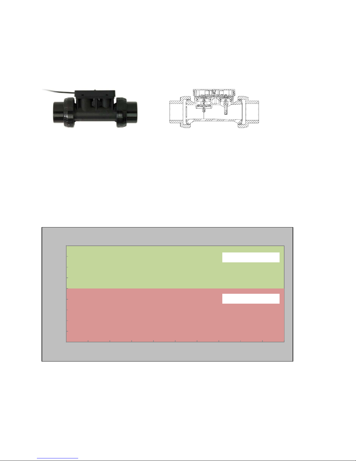
The flow meter measures the flow rate of water passing through the UV systems. The
flow meter utilizes a paddle wheel and a flow detect arm to ensure reliable
measurements.
3.7 Product Features and Benefits
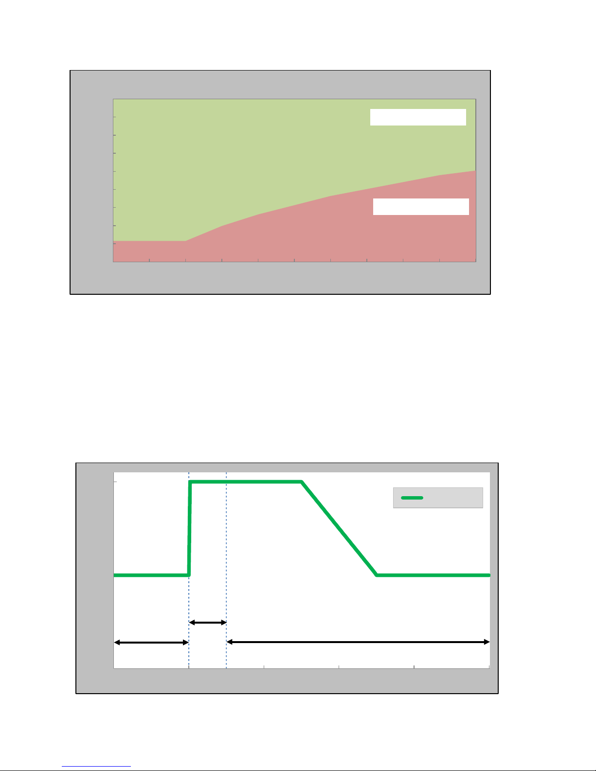
3.7.1 Real-Time UV Dose Monitoring
VIQUA’s PRO systems come equipped with real-time UV dose monitoring which utilizes
data from both the flow meter and the UV sensor.
Benefits
• More accurate assessment of true operating conditions.
• More time between maintenance.
• Lower probability of false alarms.
Standard UV System Dose Alarm
85
80
75
70
65
60
%UVT
55
50
45
40
0 10 20 30 40 50 60 70 80 90 100
% of Rated System Flow
Normal operation
System alarm
12
Page 16
% of Rated System Flow
85
Real Time Dose UV System
80
75
70
65
60
%UVT
55
50
45
40
0 10 20 30 40 50 60 70 80 90 100
3.7.2 LightWise™ Technology
VIQUA’s new LightWise™ technology allows the system’s electronic controller to
automatically reduce lamp power during periods of no water flow. The dimmi ng
capability ultimately reduces the rate of sleeve fouling.
Benefits
• Lower maintenance; up to 60% less maintenance.
• Lower energy consumption; estimated savings of 30%.
• Lower operating temperature; maintained below 40°C in typical no flow conditi ons.
• Increased electrical efficiency minimizes carbon footprint.
Normal operation
System alarm
100
50
Relative Power (%)
No Flow
0
0 1 2 3 4 5
Flow
Power Level
No Flow
Time (min)
13
Page 17
Dose Selection (mJ/cm2)
40
80
120
PRO10
PRO20
PRO30
3.7.3 Adjustable Alarm Set Points
The PRO10, PRO20, and PRO30 systems are all capable of programmable low UV
dose alarm set points of 40, 80, or 120 mJ /cm2. After detecting a low UV dose, a visual
and audible alarm will sound within the allowable response time (the time it takes for
three void volumes to pass through the system, plus 3 seconds), as per NSF Standard
55 Class A protocol.
System
Benefits
• Allows for system compliance with regional regulations.
• Ability to tailor low UV alarm set point to custom applica ti on.
• Reliable system response time to alarm situations.
• Visual and audible alarm activation.
3.8 Signals and Remote Capabilities
3.8.1 COMMcenter™
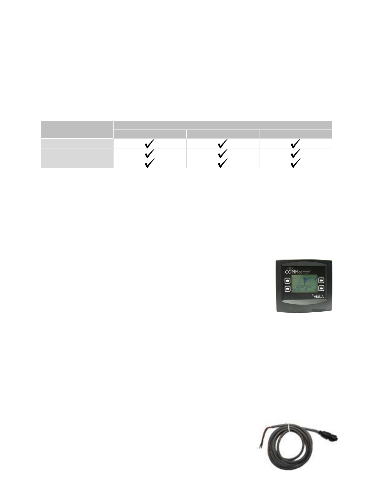
The COMMcenter™ provides live monitoring and records past
performance. When a Mini-SD card is inserted into the system,
information is recorded every minute. A 512 MB Mini-SD card should
store 18 years-worth of information. Without the Mini-SD, the
COMMcenter™ will store the last 40 alarms that have occurred in
memory.
Features
• Displays real-time dose measurements.
• Notifies alarm situations and provides help screens to overcome the problem.
• Archives past performance, water quality changes, power failures, alarms, and lamp
age.
• RJ45 Ethernet cable connection between COMMcenter™ and controller.
• Equipped with a 2 GB Micro-SD card and Mini-SD adapter.
3.8.2 Dry Contacts
The dry contact can be used to signal a remote device in event
of the following major alarms:
14
Page 18
• Lamp Fault
• Ballast (Controller) Fault
• UV Sensor Fault
• Low UV Fault
Connection Logic Chart
Wire Output Terminal
RED
BLACK
GREEN
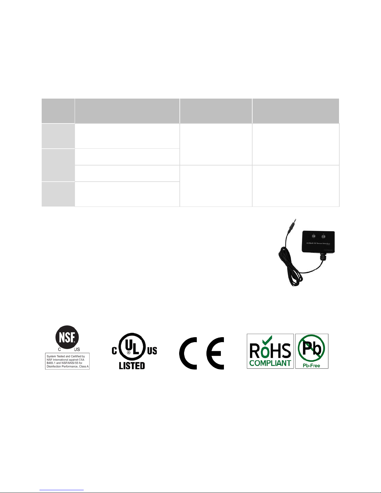
3.8.3 4-20 mA Interface
An optional 4-20 mA interface allows the user to read the current
output by the UV sensor or the flow meter. The interface can be
used to send information to other monitoring systems.
N.O. (Normally Open
Contact)
COM. (Common)
COM. (Common)
N.C. (Normally Closed
Contact)
UV System in
Normal Operation
The Electrical path
between these
contacts are closed
The Electrical path
between these
contacts are open
UV System in Major
alarm/not powered on
The Electrical path
between these contacts
are open
The Electrical path
between these contacts
are closed
4.0 C
All PRO systems are tested and certified to NSF Standard 55 Class A, UL, CE, RoHS,
and Low Lead standards.
ERTIFICATIONS
5.0 WARRANTY
VIQUA warrants the system components to be free from defects in material and
workmanship for the time specified in the table below. During this time, VIQUA will
repair or replace, at its option, any defective parts covered by the warranty.
15
Page 19

Component
Warranty
UV Chamber ten (10) years from the date of purchase
Electrical (controller) and Hardware
Components
five (5) years fr om the date of purc h as e
UV Lamps, Sleeves, and UV Sensors one (1) year from the d ate o f purc hase
16
Page 20
VIQUA DECLARATION
VIQUA is a sustainable business that designs and builds industry-leading UV systems.
Our products are used worldwide in applications that help improve quality of life.
VIQUA utilizes quality materials and processes to ensure each product meets safety,
health and environmental protection requirements. VIQUA’s product development
process ensures comprehensive product validation and certification.
VIQUA manufactures each UV disinfection system to the highest quality standards.
Each system is subjected to rigorous functional testing prior to shipment to guarantee
proper operation.
VIQUA is an ISO9001:2008 registered company.
425 Clair Rd. W, Guelph, Ontario, Canada N1L 1R1
Tel: (+1) 519-763-1032 • Toll Free: (+1) 800-265-7246 (US and Canada)
Tel: (+31) 73 747 0144 (Europe) • Fax: (+1) 519-763-5069
E-mail: [email protected]
www.viqua.com
 Loading...