

Viqua IHS12-D4, IHS22-D4, IHS22-E4 Owner's Manual
425 Clair Rd. W, Guelph, Ontario, Canada N1L 1R1
t. (+1) 519.763.1032 • f. (+1) 800.265.7246 (US and Canada only)
t. (+31) 73 747 0144 (Europe only) • f. (+1) 519.763.5069
e-mail: info@viqua.com
www.viqua.com
425 Clair Rd. W, Guelph, Ontario, Canada N1L 1R1
t. (+1) 519.763.1032 • f. (+1) 800.265.7246 (US et Canada seulement)
t. (+31) 73 747 0144 (Europe seulement) • f. (+1) 519.763.5069
Courriel : info@viqua.com
www.viqua.com
425 Clair Rd. W, Guelph, Ontario, Canadá N1L 1R1
t. (+1) 519.763.1032 • f. (+1) 800.265.7246 (solo EE. UU. y Canadá)
t. (+31) 73 747 0144 (solo Europa) • f. (+1) 519.763.5069
correo electrónico: info@viqua.com
www.viqua.com
425 Clair Rd. W, Guelph, Ontario, Canada N1L 1R1
t. (+1) 519.763.1032 • f. (+1) 800.265.7246 (US and Canada only)
t. (+31) 73 747 0144 (Europe only) • f. (+1) 519.763.5069
e-mail: info@viqua.com
www.viqua.com
Models:
IHS12-D4
IHS22-D4
IHS22-E4
Owner’s Manual
Powered by
520166-R_RevM
Congratulations on the purchase of your ultraviolet (UV) water disinfection
system! This system uses the most advanced UV technology on the market and is
designed to provide you with years of trouble free operation with minimal maintenance
required to protect your drinking water from microbiological contaminants.
To ensure ongoing disinfection of your water, UV lamps need to be replaced annually
with VIQUA factory-supplied replacem
ents. VIQUA lamps are the result of extensive
development resulting in a highly efficient disinfection platform with extremely stable UV
output over the entire 9000 hour lifetime. Its success has led to a proliferation of
non-genuine copies in the market.
The UV lamp is the heart of the disinfection system, and there should be no compromise
when it's time for a replacement.
Why should you insist on genuine factory supplied VIQUA replacement lamps?
• Use of wi
dely available, non-genuine, replacement lamps has been shown to damage
the control module of VIQUA UV disinfection equipment.
• An increasi
ng number of calls to VIQUA Technical Support are connected with
non-genuine lamps being used (unknowingly) as replacements.
• Damage arisi
ng from the use of non-genuine lamps poses a safety risk and is not
covered by equipment warranty.
• Unless the UV equi
pment is equipped with a UV sensor (monitor), it is not possible to
verify the UV (invisible) output of replacement lamps.
• Similar appearance to the origi
nal lamp and the presence of (visible) blue light does
not mean equivalent disinfection performance.
• VIQUA replacement lamp
s undergo rigorous performance testing and strict quality
control processes to ensure that the safety and performance certifications of the
original equipment are not compromised.
So, you can see that it's simply not worth the risk! Insist on genuine VIQUA replacement
lamps.
2 47
Garantía del fabricante
Sección 8 Garantía del fabricante
Nuestro compromiso
VIQUA se compromete a asegurar que su experiencia con nuestros productos y organización superen sus expectativas.
Hemos fabricado el sistema de desinfección UV según los más altos estándares y lo valoramos como cliente. Si necesitara
soporte técnico o tiene preguntas acerca de su sistema, póngase en contacto con nuestro equipo de soporte técnico en el
1.800.265.7246 o en technicalsupport@viqua.com. Estaremos encantados de ayudarle. Esperamos que disfrute de las
ventajas que ofrece un agua potable limpia y segura después de la instalación del sistema de desinfección VIQUA.
Cómo realizar una reclamación bajo garantía
Nota: Para maximizar el rendimiento de desinfección y la fiabilidad de su producto VIQUA, el sistema se debe
dimensionar, instalar y mantener adecuadamente. En el manual del propietario encontrará información de utilidad
sobre los parámetros de calidad del agua necesarios y los requisitos de mantenimiento.
En el caso de que se necesitara una reparación o reposición de piezas cubiertas bajo esta garantía, el proceso lo
gestionará el distribuidor. Si no está seguro de si un problema o fallo del sistema está cubierto por la garantía, póngase en
contacto con nuestro equipo de soporte técnico en el 1.800.265.7246 o por correo electrónico en la dirección
technicalsupport@viqua.com. Nuestro técnicos completamente formados le ayudarán a resolver el problema e identificar
una solución. Tenga a mano el número de modelo (tipo de sistema), la fecha de compra, el nombre del distribuidor al que
adquirió el producto VIQUA ("distribuidor de origen") y una descripción del problema que está experimentando. Para
establecer la prueba de compra al realizar una reclamación bajo garantía, ne cesitará su factura original, o bien deberá
haber completado y enviado su tarjeta de registro de producto por correo postal o en línea.
Cobertura específica de la garantía
La cobertura de la garantía es específica de la gama de productos de VIQUA. La cobertura de la garantía está sujeta a las
condiciones y limitaciones establecidas en la sección "Condiciones y limitaciones generales".
Garantía limitada de diez años para la cámara UV de VIQUA
VIQUA garantiza que la cámara UV del producto VIQUA estará libre de defectos de material y mano de obra durante un
período de diez (10) años desde la fecha de compra. Durante este período, VIQUA reparará o reemplazará, a su criterio,
toda cámara UV VIQUA defectuosa. Devuelva la pieza defectuosa a su distribuidor, quién procesará su reclamación.
Garantía limitada de tres años para los componentes eléctricos y de hardware
VIQUA garantiza que los componentes eléctricos (controlador) y de hardware estarán libres de defectos de material
y mano de obra durante un período de tres (3) años desde la fecha de compra. Durante este período, VIQUA reparará
o reemplazará, a su criterio, toda pieza defectuosa cubierta por la garantía. Devuelva la pieza defectuosa a su distribuidor,
quién procesará su reclamación.
Garantía limitada de un año para lámparas UV, vainas tubulares y sensores UV
VIQUA garantiza que las lámparas UV, las vainas tubulares y los sensores UV estarán libres de defectos de material
y mano de obra durante un período de un (1) año desde la fecha de compra. Durante este período, VIQUA reparará
o reemplazará, a su criterio, toda pieza defectuosa cubierta por la garantía. Su distribuidor procesará su reclamación
y ofrecerá consejos sobre si el artículo defectuoso se debe devolver para realizar un análisis de fallos.
Nota: Utilice únicamente lámparas y vainas tubulares de reposición VIQUA originales en el sistema. El incumplimiento de
este requisito podría poner en riesgo el rendimiento de la desinfección y afectar a la cobertura de la garantía.
Condiciones y limitaciones generales
Ninguna de las garantías anteriores cubre los daños provocados por el uso o mantenimiento inadecuados, accidentes,
actos de la naturaleza o arañazos e imperfecciones menores que no afectan materialmente el funcionamiento del
producto. Las garantías tampoco cubren los productos que no se han instalado según las instrucciones del manual del
propietario correspondiente.
Las piezas reparadas o reemplazadas según estas garantías serán cubiertas bajo garantía hasta el final del período de
garantía aplicable a la pieza original.
Las garantías anteriores no incluyen el coste de envío y manipulación de los artículos devueltos. Las garantías limitadas
que se describen anteriormente son las únicas garantías aplicables a la gama de productos VIQUA. En estas garantías
limitadas se describe el único recurso para todas las reclamaciones basadas en un fallo o defecto de cualquiera de estos
productos, ya sea que la reclamación se base en contrato, agravio (incluida la negligencia), responsabilidad estricta u otro.
Estas garantías reemplazan a todas las demás garantías escritas, orales, implícitas o reglamentari as. No corresponde, sin
limitación, ninguna garantía de comerciabilidad o aptitud para un propósito particular a ninguno de estos productos.
VIQUA no asume ninguna responsabilidad por lesiones o daños a la
propiedad causados por el uso o el mal uso de
cualquiera de los productos mencionados anteriormente. VIQUA no será de ningún modo responsable de los daños
especiales, incidentales, indirectos o consecuentes. La responsabilidad de VIQUA se limitará, en todos los casos, a la
reparación o reposición del producto o la pieza defectuosa y esta responsabilidad finalizará al finalizar el período de
garantía aplicable.
Section 1 Safety Information
Please read this entire manual before operating this equipment. Pay attention to all danger , warning, and caution statemen ts
in this manual. Failure to do so could result in serious personal injury or damage to the equipment.
Make sure that the protection provided by this equipment is not imp
aired. DO NOT use or install this equipment in any
manner other than that specified in the installation manual.
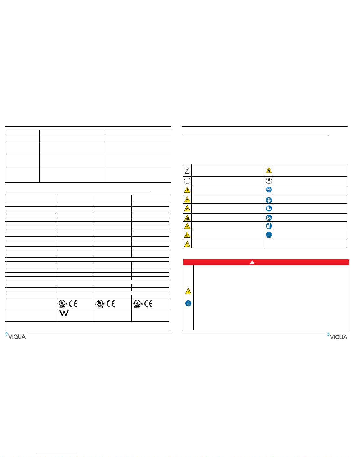
1.1 Potential Hazards:
Read all labels and tags attached to the system. Personal injury or damage to the system could occur if not observed.
Waste electrical and electronic equipment (WEEE). This symbol
indicates that you should not discard wasted electrical or electronic
equipment (WEEE) in the trash. For proper disposal, contact your
local recycling/reuse or hazardous waste center.
This symbol indicates not to store any combustible or flammable
material close to the system.
Hg
This symbol indicates there is Mercury present.
This symbol indicates that the contents of the transport package are
fragile and the package should be handled with care.
This is the safety alert symbol. Obey all safety messages that follow
this symbol to avoid potential injury. When on the equipment, refer to
the Operational and Maintenance manual for additional safety
This symbol indicates safety glasses with side protection is required
for protection against UV exposure.
This symbol indicates a risk of electrical shock and/or electrocution
exists.
This symbol indicates gloves must be worn.
This symbol indicates the marked equipment may contain a
component that can eject forcibly. Obey all procedures to safely
depressurize.
This symbol indicates safety boots must be worn.
This symbol indicates the system is under pressure.
This symbol indicates the operator must read all available
documentation to perform required procedures.
UV
This symbol indicates there is a potential UV hazard. Proper
protection must be worn.
Cu
This symbol indicates the plumber must use copper piping.
This symbol indicates the marked item could be hot and should not
be touched without care.
This symbol indicates that the system should only be connected to a
properly grounded, grounding-type controller receptacle that is
protected by a Ground Fault Circuit Interrupter (GFCI).
This symbol indicates there is a potential for VERY hot water when
flow is started.
Warning: T
his product may contain chemicals known to the State of California to cause cancer and birth defects or other reproductive harm.
1.2 Safety Precautions:
DANGER
• Electric Shock: To avoid possible electric shock, special care should be taken since water is present near the electrical equipment. Unless a
situation is encountered that is explicitly addressed by the provided maintenance and troubleshooting sections, DO NOT attempt repairs yourself,
refer to an authorized service facility.
• GROUNDING: T
his product must be grounded. If it should malfunction or breakdown, grounding provides a path of least resistance for electric
current to reduce the risk of electrical shock. This system is equipped with a cord having an equipment-grounding conductor and a grounding plug.
The plug must be plugged into an appropriate outlet that is properly installed and grounded in accordance with all local codes and ordinances.
Improper connection of the equipment-grounding conductor can result in a risk of electrocution. Check with a qualified electrician or service
personnel if you are in doubt as to whether the outlet is properly grounded. DO NOT modify the plug provided with this system – if it does not fit in
the outlet, have a proper outlet installed by a qualified electrician. DO NOT use any type of adapter with this system.
• GROUND FAULT CIRCUIT INTERRUPTER PROTECTION: T
o comply with the National Electrical Code (NFPA 70) and to provide additional
protection from the risk of electric shock, this system should only be connected to a properly grounded, grounding-type controller receptacle that is
protected by a Ground Fault Circuit Interrupter (GFCI). Inspect operation of GFCI as per manufacturer’s suggested maintenance schedule.
• DO N
OT operate the disinfection system if it has a damaged cord or plug, if it is malfunctioning or if it has been dropped or damaged in any
manner.
• DO NOT use this disinfection system for
other than intended use (potable water applications). The use of attachments not recommended or sold by
the manufacturer / distributor may cause an unsafe condition.
• DO N
OT install this disinfection system where it will be exposed to the weather or to temperatures below freezing.
• DO N
OT store this disinfection system where it will be exposed to the weather.
• DO N
OT store this disinfection system where it will be exposed to temperatures below freezing unless all water has been drained from it and the
water supply has been disconnected.
Failure to follow these instructions will result in serious in
jury or death.
Safety Information
46 3
Especificaciones
Sección 7 Especificaciones
Alarma Consulte Sección 5.1. Consulte Sección 5.1.
El sistema funciona pero las
pruebas de agua indican
contaminación bacteriana
• Los equipos instalados aguas abajo del sistema UV
funcionan como caldo de cultivo de agentes patógenos
• Hay agentes patógenos que residen en las líneas de
distribución posteriores al tratamiento UV
• Recontaminación de extremos sin salida de la canalización
• Asegurarse de que UV sea el último equipo de tratamiento.
• Asegurarse de que todas las líneas de distribución se
hayan desinfectado con cloro. Consulte Sección 3.2.
• Quitar los extremos sin salida de la canalización
y enjuagar con cloro. Consulte Sección 3.2.
El temporizador de la lámpara
no realiza ninguna lectura
• La unidad está desenchufada
• La toma de corriente de CA no tiene alimentación
• El cable de alimentación está dañado
• Una subida de tensión causó daños al conjunto eléctrico
• Enchufar la unidad a una toma de corriente de CA
• Reemplazar el fusible o restablecer el contacto
• Reemplazar el cable de alimentación
• Reemplazar el controlador y usar un protector de
sobretensiones (TVSS)
Fuga detectada en los filtros
• Junta tórica dañada, deteriorada o instalada de manera
incorrecta
• Cartucho de filtro no centrado
• Quitar el cárter, limpiar la junta tórica y las roscas.
Asegurarse de que la junta tórica se haya colocado
correctamente y volver a instalar
• Quitar el cárter, inspeccionar el cartucho para ver si está
dañado, volver a ensamblar asegurándose de que el
cartucho esté centrado
IHS12-D4 / IHS12-D4/2 /
IHS12-D4/2A
IHS22-E4 /
IHS22-E4/2
IHS22-D4 /
IHS22-D4/2
Parámetros de funcionamiento
Presión máxima de funcionamiento 100 PSI (689 kPa) 100 PSI (689 kPa) 100 PSI (689 kPa)
Presión mínima de funcionamiento 4 PSI (27,5 kPa) 4 PSI (27,5 kPa) 4 PSI (27,5 kPa)
Temperatura máxima del aire ambiental 50 ºC (122 ºF) 50 ºC (122 ºF) 50 ºC (122 ºF)
Temperatura mínima del aire ambiental 2 ºC (36 ºF) 50 ºC (122 ºF) 50 ºC (122 ºF)
Humedad máxima 95 % 95 % 95 %
Dureza máxima 120 ppm (7 granos por 3,79 litros) 120 ppm (7 granos por 3,79 litros) 120 ppm (7 granos por 3,79 litros)
Nivel máximo de hierro 0,3 ppm 0,3 ppm 0,3 ppm
Transmisión UV mínima 75 % 75 % 75 %
Caudales
Certificado de clase B NSF a una dosis de
16 mJ/cm
2
a 70 % TUV*
8,9 gpm (33,7 lpm) (2 m
3
/h) _ _
Caudal máximo a una dosis de 16 mJ/cm
2
** 16 gpm (60 lpm) (3,6 m3/h) N/A
1
16 gpm (60 lpm) (3,6 m3/h)
Caudal máximo a una dosis de 30 mJ/cm
2
** 12 gpm (45 lpm) (2,7 m3/h) 22 gpm (83 lpm) (4,95 m3/h) 22 gpm (83 lpm) (4,95 m3/h)
Caudal máximo a una dosis de 40 mJ/cm
2
** 9 gpm (34 lpm) (2 m3/h) 16 gpm (60 lpm) (3,6 m3/h) 9 gpm (34 lpm) (2 m3/h)
Eléctrico
Voltaje CA de 100 a 240 V CA de 100 a 240 V CA de 100 a 240 V
Frecuencia 50 a 60 Hz 50 a 60 Hz 50 a 60 Hz
Corriente máxima 0,5 Amp 0,85 Amp 0,5 Amp
Consumo eléctrico máximo 50 vatios 83 vatios 50 vatios
Potencia de la lámpara 40 vatios 70 vatios 40 vatios
Otros
Material de la cámara UV 304 SST 304 SST 304 SST
Entrada/salida NPT de 1,905 cm NPT de 2,54 cm NPT de 1,905 cm
Otros
Ciclo de vida nominal de la lámpara 1 año 1 año 1 año
Certificación del sistema UV
Solo IHS12-D4/2A
1
El caudal máximo lo determina el filtro de carbón.
*Caudales solo para IHS12-D4/2A.
**Los caudales que se muestran son a TUV del 95 %.
Síntoma Causa probable Posible solución
License# 035007
NSF International
CAUTION
• Carefully examine the disinfection system after installation. It should not be plugged in if there is water on parts not intended to be wet such as, the
controller or lamp connector.
• D
ue to thermal expansion concerns and potential material degradation due to UV exposer, it is recommended to use metal fittings and at least 10”
of copper pipe on the outlet of your UV chamber.
• T
he UV lamp inside the disinfection system is rated at an effective life of approximately 9000 hours. To ensure continuous protection, replace the
UV lamp annually.
• T
he UV system is not to be used or played with by children. Persons with reduced physical, sensory or mental capabilities, or lack of experience
and knowledge, are also not to handle the UV system unless they have been given supervision or instruction.
• EXTENSION CORDS: If an extensio
n cord is necessary, use only 3-wire extension cords that have 3-prong grounding-type plugs and 3-pole cord
connectors that accept the plug from this system. Use only extension cords that are intended for outdoor use. Use only extension cords having an
electrical rating not less than the rating of the system. A cord rated for less amperes or watts than this system rating may overheat. Exercise caution
when arranging the cord so that it will not be tripped over or pulled. DO NOT use damaged extension cords. Examine extension cord before using
and replace if damaged. DO NOT abuse extension cord. Keep extension cord away from heat and sharp edges. Always disconnect the extension
cord from the receptacle before disconnecting this system from the extension cord. Never yank cord to pull plug from outlet. Always grasp the plug
and pull to disconnect.
• SYSTEM PROTECTION:
To protect your Controller, a UL1449 certified (or equivalent) transient voltage surge suppressor is strongly
recommended.
• T
he UV lamp in this system conforms to the applicable provisions of the Code of Federal Regulations (CFR) requirements including, Title 21,
Chapter 1, Subchapter J, Radiological Health.
• R
ead and understand the Owner’s Manual before operating and performing any maintenance on this equipment.
1.3 Water Chemistry
Water quality is extremely important for the optimum performance of your UV system. The following levels are
recommended for installation:
* Where total hardness is less than 7 gpg, the UV unit should o
perate efficiently provided the quartz sleeve is cleaned
periodically. If total hardness exceeds 7 gpg, the wate r should be softened. If your water chemistry contains levels in excess
of those mentioned above, proper pre-treatment is recommended to correct these water problems prior to the installation of
your UV disinfection system. These water quality parameters can be tested by your local dealer, or by most private analytical
laboratories. Proper pre-treatment is essential for the UV disinfection system to operate as intended.
WAR N IN G
During extended periods of no water flow, the water in your chamber can become very hot (Approx. 60 °C) and potentially lead to scalding. It is
recommended to run your water until this hot water has been purged from your chamber. Do not allow water to contact your skin during this time. To
eliminate this condition, a temperature management valve can be installed at the outlet of your UV system.
Failure to follow these instructions could result in minor or moderate injury.
NOTICE
Water Quality and Minerals Level
Iron < 0.3 ppm (0.3 mg/L)
Hardness* < 7 gpg (120 mg/L)
Turbidity < 1 NTU
Manganese < 0.05 ppm (0.05 mg/L)
Tannins < 0.1 ppm (0.1 mg/L)
UV Transmittance > 75% (call factory for recommendations on applications where UVT < 75%)
Safety Information
4 45
Funcionamiento
Sección 5 Funcionamiento
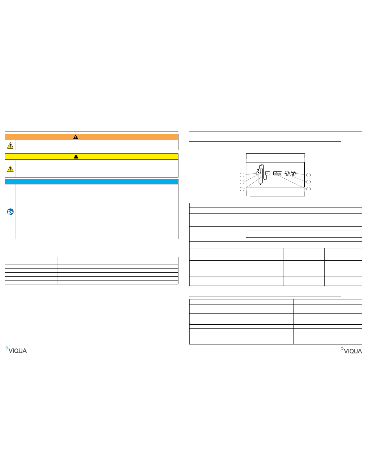
5.1 Controlador
Sección 6 Solución de problemas
Figura 3 Controlador
Botones y pantalla
Característica Descripción Función
A
Pantalla del temporizador de la
lámpara
Hace la cuenta atrás a partir de los 365 días para mostrar el momento de la reposición anua l de la lámpara.
B
Restablecimiento del
temporizador de la lámpara
Después de instalar una lámpara nueva, mantener pulsado durante cinco segundos para restablecer el
temporizador de la lámpara en 365.
C Silencio
Presionar para silenciar la alarma sonora.
Cuando la alarma se debe a la antigüedad de la lámpara, el botón Silencio silenciará la alarma sonora durante
7 días; esto se puede repetir un máximo de 4 veces. Luego, el botón se silenciará solo durante 24 horas.
Cuando la alarma se debe a algún otro problema, el botón Silenciar silenciará la alarma sonora durante 24 horas.
Luces indicadoras
LED Verde Amarillo Parpadea en rojo Rojo continuo
1
Opción no disponible en este
sistema
Opción no disponible en este
sistema
Opción no disponible en este
sistema
Opción no disponible en este
sistema
2
La lámpara funciona con
normalidad
Advertencia: La lámpara se
deberá reemplazar
próximamente
• Lámpara desconectada;
desconectar la alimentación,
volver a conectar la lámpara y
conectar el controlador
• Fallo de la lámpara;
reemplazar la lámpara
Lámpara inactiva debido a un
fallo del controlador
3
El controlador funciona con
normalidad
La temperatura del aire
alrededor del sistema es
demasiado cálida
Fallo del controlador; reemplazar el
controlador
Fallo del controlador; reemplazar
el controlador
Síntoma Causa probable Posible solución
Sin potencia
• Disparo del GFCI o contacto
• Supresor de tensiones transitorias (TVSS) dañado
• Controlador dañado
• Restablecer el GFCI o contacto.
• Reemplazar TVSS
• Reemplazar el controlador y usar TVSS
Disparo repetido del
GFCI o contacto
• La conexión entre la lámpara y el enchufe de la lámpara
está mojada
• Cortocircuito en el conjunto eléctrico
• Limpiar y secar las clavijas de la lámpara y el enchufe de
la lámpara; inspeccionar la unidad en búsqueda de fugas
o condensación
• Reemplazar el controlador
Fuga en la entrada o salida Hay una fuga en los accesorios de canalización con rosca
Limpiar las roscas, volver a sellar con cinta Teflon y volver a apretar
Fuga detectada en el área de
la cámara UV
• Condensación de aire húmedo en la cámara fría
(acumulación lenta)
• Junta tórica dañada, deteriorada o instalada de manera
incorrecta
• Conjunto de lámpara/vaina tubular no instalado
correctamente (demasiado o insuficientemente apretado)
• Controlar la humedad o cambiar la ubicación de la
unidad
• Inspeccionar la junta y reemplazar si está deteriorada
• Apretar el conjunto con la mano
3
2
1
C
B
A
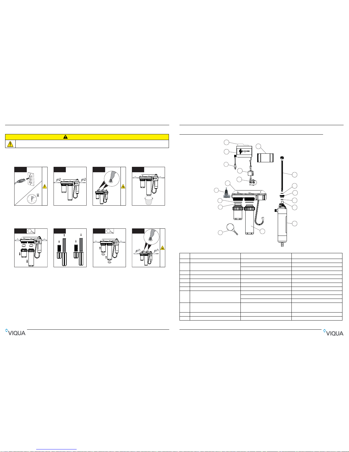
Section 2 General Information
1
2
3
9
6
5
10
14
13
12
13
16
15
17
4
8
11
7
Figure 1 System Components
Item Description Part Number UV System
1 Sump wrench WR40-50 Used on all systems.
2 Sediment filter
CMB-510-HF IHS12-D4, IHS12-D4/2, IHS12-D4/2A
CMB-520-HF IHS22-E4, IHS22-E4/2, IHS22-D4, IHS22-D4/2
3 O-ring OR40-50 Used on all systems.
4 Pressure reducing valve 410992-R IHS12-D4/2A
5Bracket - 6 Lamp cord - 7 Safety cap 603000 Used on all systems.
8 Power cord
602636 (120V) Used on all systems.
602637 (230V) Used on all systems.
260013 (Australian) Used on all systems.
9
Controller
(includes Controller mounting bracket,
Reference card, Safety cap, Lamp cord)
650713-007 Used on all systems.
10 Reference card 603069 Used on all systems.
11 Controller mounting bracket - -
General Information
44 5
4.3 Reposición de los cartuchos
Es recomendable cambiar los cartuchos de filtro periódicamente (3 a 4 veces al año) en función de la calidad y el uso del
agua. Una reducción gradual en la presión del agua después del dispositivo de filtrado es una indicación que los cartuchos
previos al filtro están llegando al final de su vida útil.
Procedimiento:
PRECAUCIÓN
Las carcasas del cárter serán pesadas.
1
0
30
15
45
10 mins
• Desconecte la fuente de
alimentación principal y deje
que la unidad se enfríe
durante 10 minutos.
2
• Corte el suministro de agua.
• Cierre los grifos.
3
• Pulse el botón de presión
para liberar la presión de los
cartuchos.
4
• Quite el tapón de drenaje de
la parte inferior del cárter
y coloque un cubo para
atrapar el agua.
• Vuelva instalar el tapón de
drenaje.
5
11
2
2
• Quite ambas carcasas con
una llave para filtros de agua.
6
Antiguo Nuevo
• Extraiga y descarte los
cartuchos viejos.
• Instale los cartuchos nuevos.
7
1
1
2
2
• Vuelva a instalar las
carcasas.
8
• Abra un grifo aguas abajo del
sistema.
• Restaure la alimentación y
active el suministro de agua.
• Cierre el grifo aguas abajo.
• Pulse el botón de presión
para purgar el aire.
Mantenimiento
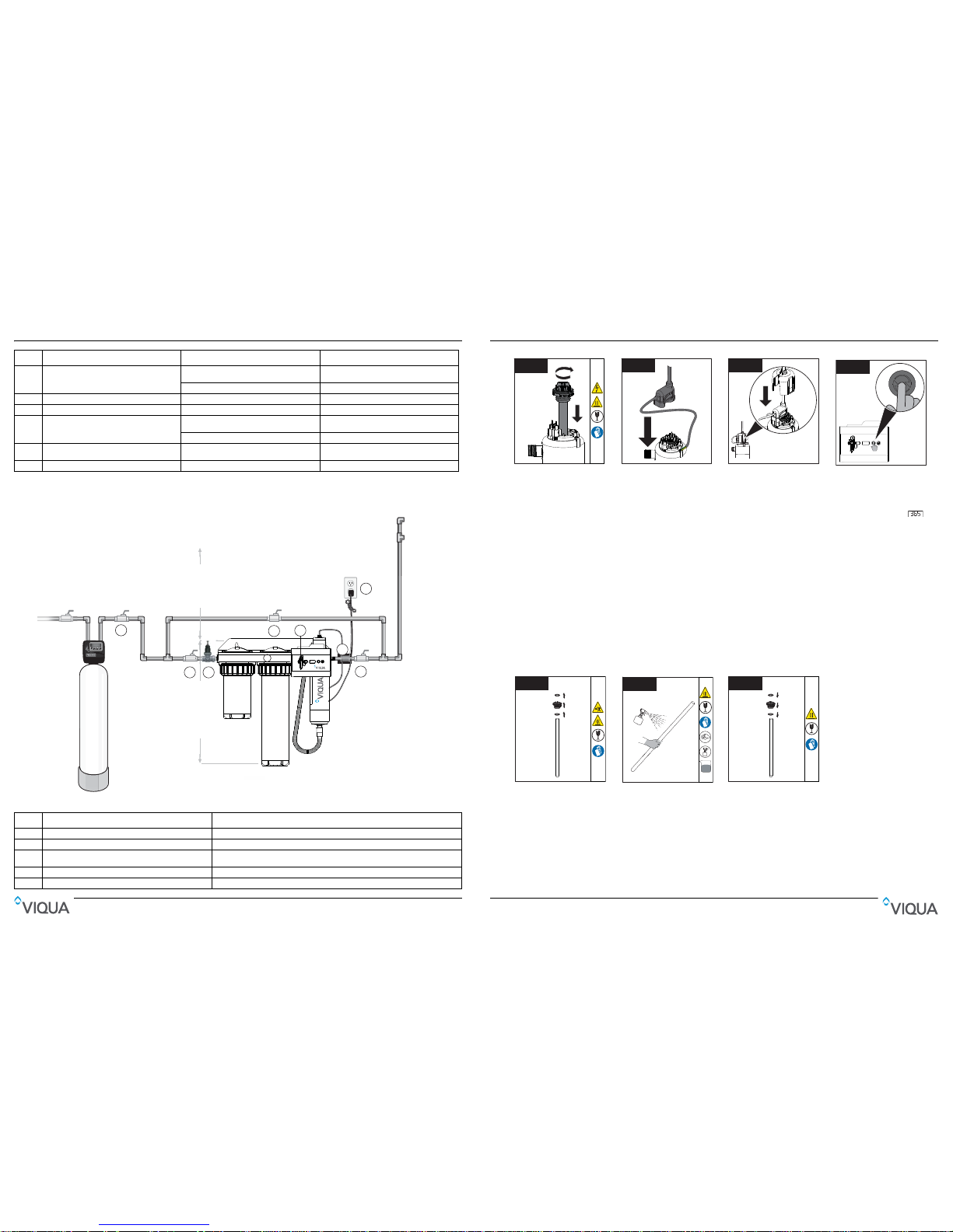
2.1 Dimensions and Layout
Main Water
Shut O
Optional By-Pass Assembly
Hot water pipe
Cold water pipe
1
2
4
7
16” Clearance for
lamp removal
6
3
8
9
Note: IHS12-D4/2A, IHS22-E4 and E4/2 come with quick connect fittings and PEX pipe.
MIN 4” from bottom of unit
for clearance for filter changes
25.5” Overall Length
Optional
Water
Softener
5
Figure 2 System - Dimension and Layout
12 Lamp (includes O-rings)
602805
IHS12-D4, IHS12-D4/2, IHS12-D4/2A,
IHS22-D4, IHS22-D4/2
602806 IHS22-E4, IHS22-E4/2
13 O-ring - Used on all systems.
14 Sleeve bolt 602665 Used on all systems.
15 Sleeve (includes O-rings)
602732
IHS12-D4, IHS12-D4/2, IHS12-D4/2A,
IHS22-D4, IHS22-D4/2
602733 IHS22-E4, IHS22-E4/2
16
UV Chamber (includes Chamber and Ring
clamp).
- Used on all systems.
17 Carbon filter C2-02 Used on all systems.
Item Description Function
1 Main water shut-off valve Allows for sampling of raw water.
2 Shut-off Valve Allows for ease of maintenance of whole home UV disinfection system.
3 Bypass shut-off valve
Bypass line and valve are optional. Intended to provide emergency water supply in the
event that the UV system is unavailable.
4 Shut-off valve Allows for ease of maintenance of whole home UV disinfection system.
5 Whole Home System Provides filtration and disinfection of the water.
Item Description Part Number UV System
General Information
6 43
4.2 Limpieza y reposición de la vaina tubular de cuarzo
Nota: Los minerales del agua van formando lentamente una capa en la vaina tubular de cuarzo de la lámpara. Esta capa
debe retirarse porque reduce la cantidad de luz UV que llega al agua, reduciendo de este modo el rendimiento de la
desinfección. Si la vaina tubular no puede limpiarse, deberá reemplazarse por otra.
Requisitos previos:
• Cortar el suministro de agua y drenar todas las líneas.
• Despresurizar el sistema. Colocar un paño pequeño debajo de la unidad para recoger el agua que pueda caer.
• Quitar la lámpara UV. Consulte Sección 4.1.
Procedimiento:
Notas: 1) Tras reemplazar la lámpara UV o la vaina tubular, realice el procedimiento de desinfección, consulte la Sección 3.2.
2) Si el sistema se desvía temporalmente o si se contamina después del sistema de desinfección, es necesario
completar el procedimiento de desinfección. Consulte Sección 3.2.
9
• Introduzca y asegure el
ensamblaje de la
lámpara/vaina tubular.
Nota: El apriete excesivo
romperá la vaina tubular
10
10
• Alinee las conexiones
girando la abrazadera de
anillo e instale el enchufe de
la lámpara.
11
11
• Introduzca la tapa de
seguridad.
1212
• Restaure la energía.
• Si se ha insertado la lámpara
nueva, mantenga pulsado el
botón de restablecimiento del
temporizador de la lámpara
durante 5 segundos. La
pantalla debería mostrar .
• Abra todos los grifos y las
entradas de agua. Luego
cierre todos los grifos
e inspeccione el equipo para
ver si hay fugas.
1
1
2
3
• Desenrosque el tornillo de la
vaina tubular y quite las
juntas tóricas de la vaina de
cuarzo.
2
Mild
Acid
• Limpie la vaina tubular de
cuarzo con un trapo empapado
en CLR, vinagre u otro ácido
blando y, a continuación,
aclárela con agua.
Nota: Si no es posible limpiar
la vaina tubular por completo
o si se raya o se quiebra,
reemplácela.
3
1
2
3
• Introduzca las juntas tóricas
y apriete el tornillo de la vaina
tubular en la vaina de cuarzo.
• Cuando haya finalizado el
servicio, realice los pasos que
aparecen en los requisitos
previos en orden inverso al
desmontaje.
Mantenimiento
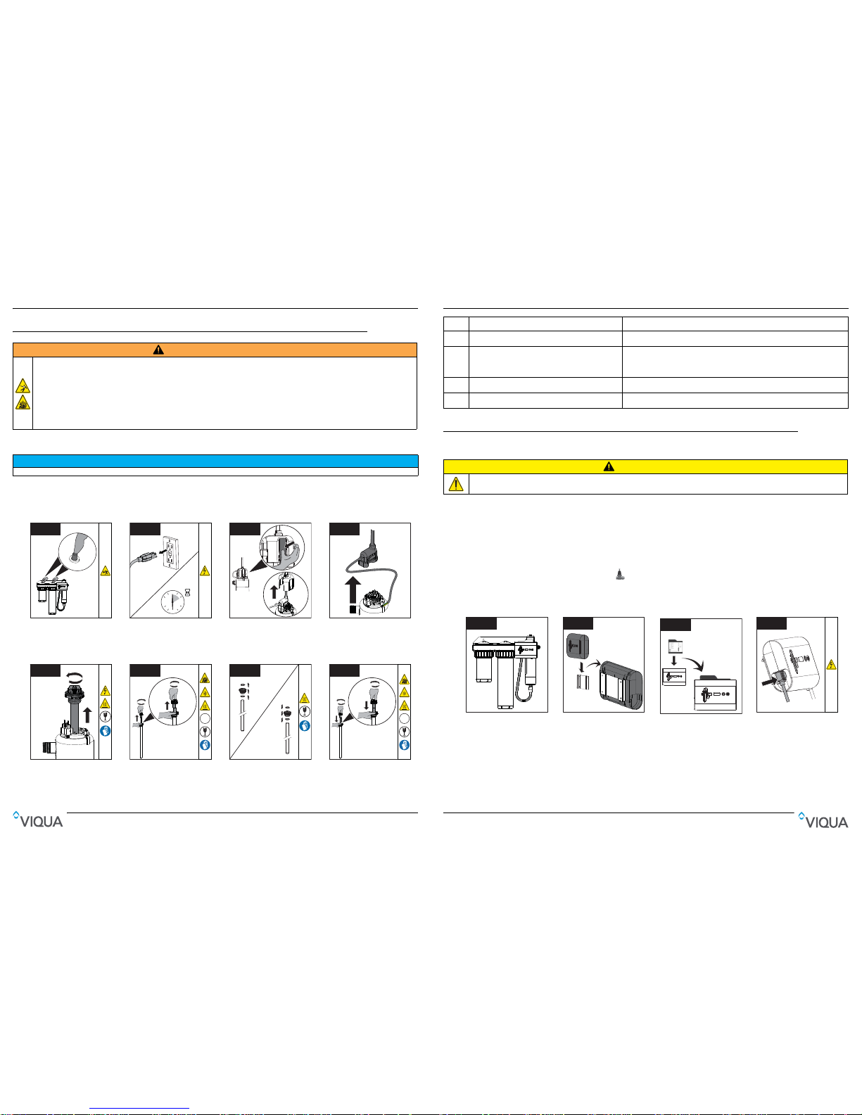
Section 3 Installation
3.1 Installing UV System
CAUTION
Prerequisites:
• Determ
ine appropriate indoor location of the controller and chamber, refer to Section 2.1.
• Make sur
e that the controller is installed higher than the chamber and away from all water sources.
• Ensur
e adequate clearance above chamber to allow for removal of the lamp and sleeve.
• Make sure to t
urn off the main water supply.
• Make all
necessary plumbing connections refer to Section 2.1.
Note: IHS1
2-D4/2A: For shipping purposes, the pressure reducing valve is shipped separately. Install it into the female
inlet and tighten by turning clockwise. A backflow device (n
ot included) is required to be installed downstream of the outlet,
in accordance with Watermark Certification Scheme (WMCS).
Procedure:
1
1
• Install the UV system on the
wall using lag bolts (not
supplied). Mounting holes are
located in the metal bracket.
2
• Slide controller onto mounting
bracket.
3
• Insert the reference card
between controller and
mounting bracket.
4
• Connect power cord to
controller.
• DO NOT connect the power
cord to the GFCI outlet at this
time.
6 Controller
Powers and controls the UV lamp and other devices. Provides human interface,
displaying information and allowing control inputs (such as muting the audible alarm).
7 Power source
Provides power to the controller. For safety reasons the outlet must be protected by a
Ground Fault Circuit Interrupter (GFCI).
Note: To protect the controller, a UL1449 certified (or equivalent) transient voltage surge
suppressor is required.
8 Pressure Reducing Valve:
Controls and maintains a preset desired reduced pressure regardless of variations in
upstream water pressure. (Only for IHS12-D4/2A)
9 Backflow device
A backflow (not included) device is required to be installed downstream of the outlet, in
accordance with the Watermark Certification Scheme (WMCS) (Only for IHS12-D4/2A).
Electronic controller must be connected to a Ground
Fault Protected Circuit (GFCI) receptacle. Ensure green ground wire ring terminal is securely
fastened to ground stud on UV chamber.
Item Description Function
Installation
42 7
Sección 4 Mantenimiento
4.1 Reemplazo de la lámpara UV
La reposición de la lámpara es un procedimiento rápido y sencillo que no necesita herramientas especiales. Se debe
reemplazar la lámpara después de 9000 horas de funcionamiento continuo (un año aproximadamente) con el fin de
garantizar una desinfección adecuada.
Procedimiento:
ADVERTENCIA
• Desconecte siempre la corriente antes de llevar a cabo cualquier trabajo en el sistema de desinfección.
• Corte siempre el flujo de agua y libere la presión del agua antes de realizar el servicio.
• Examine con frecuencia el sistema de desinfección para asegurar que los indicadores de corriente estén encendidos y que no hay ninguna alarma.
• Reemplace la lámpara UV anualmente (o cada dos años si se trata de un uso casero temporal) para garantizar la máxima desinfección.
• Drene siempre la cámara al cerrar la temporada o al dejar la unidad en un área sujeta a temperaturas de congelación.
• Durante períodos prolongados sin flujo de agua, el agua del depósito se podría calentar excesivamente (aprox. 60 °C) y provocar quemaduras.
Se recomienda hacer correr el agua hasta que se haya drenado el agua caliente del depósito. Durante esta operación, evite que el agua entre en
contacto con la piel. Para eliminar esta condición, se puede instalar una válvula de control de la temperatura en la salida del sistema UV.
AV I S O
No utilice agua durante la reposición de la lámpara UV.
1
• Cierre todos los grifos
y suministros de agua.
• Pulse el botón de presión
para liberar la presión de los
cartuchos.
2
0
30
15
45
10 mins
• Desconecte la fuente de
alimentación principal y deje
que la unidad se enfríe
durante 10 minutos.
3
1
2
• Quite la tapa de seguridad
apretando la pestaña.
Nota: Asegúrese de que los
cables del enchufe de la lámpara
permanezcan conectados.
4
• Quite el enchufe de la lámpara.
Nota: Asegúrese de que los
cables de liberación de tensión
y conexión a tierra
permanezcan conectados.
5
2
1
• Gire el conjunto de
lámpara/vaina tubular hacia
la izquierda y tire de la
lámpara hacia arriba para
extraerla de la cámara.
6
Hg
UV
1
1
2
2
• Sostenga el perno de la vaina
tubular para extraer la
pestaña de la lámpara junto
con la lámpara UV.
7
1
2
3
1
2
3
•
Desenrosque el perno de la
vaina tubular y quite las dos
juntas tóricas de la vaina tubular.
•
Introduzca las dos juntas tóricas
y apriete el perno de la vaina
tubular contra la vaina tubular.
8
Hg
UV
2
2
1
1
• Instale y asegure la lámpara
nueva en la vaina tubular.
Nota: Si se aprieta
demasiado, se romperá la
vaina.
Mantenimiento
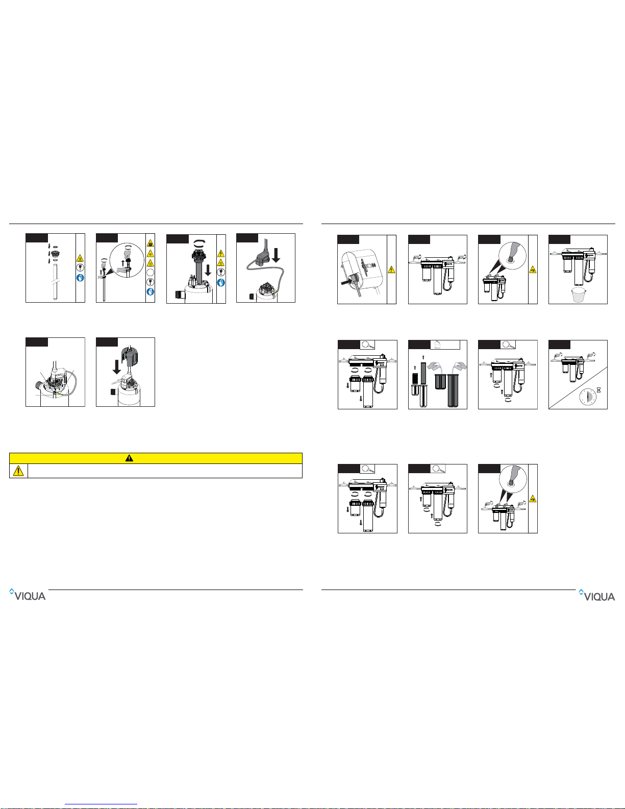
5
1
2
3
• Install the sleeve bolt with 2
new O-rings.
6
Hg
UV
1
1
2
2
• Install the lamp into sleeve
and hand tighten.
Note: Over tightening will
break the sleeve.
7
• Insert the lamp/sleeve
assembly into chamber,
screw hand tight.
Note: Over tightening will
break the sleeve.
8
• Align connections by rotating
the ring clamp and install the
lamp plug.
9
Locking
Screw
Ground
Lug
Ground and
strain relief
wires
• Attach ground and strain
relief wires from the lamp
plug to the ground lug on the
chamber. Secure both wires
with locking screw provided.
1010
• Insert the safety cap.
• Restore power.
• Open all faucets and turn on
water supply. Inspect for any
leaks.
3.2 Disinfection Procedure
CAUTION
UV disinfection is a physical disinfection process and does not add any potentially harmful chemicals to the water. As UV
does not provide a disinfection residual, it is imperative that the entire distribution system located after the UV be chemically
disinfected to ensure that the plumbing system is free from any bacteriological contaminants. The disinfection process must
be performed immediately after the UV unit is installed and repeated thereafter whenever the UV is shut down for service,
without power, or inoperative for any reason. The procedure for sanitizing the plumbing system is readily accomplished as
follows:
The sump housings will be heavy.
Installation
8 41
1
• Asegúrese de que el
controlador esté conectado
durante todo el proceso de
desinfección.
2
• Corte el suministro de agua.
• Cierre los grifos.
3
• Pulse el botón de presión
para liberar la presión de los
cartuchos.
4
• Quite el tapón de drenaje de
la parte inferior del cárter
y coloque un cubo para
atrapar el agua.
• Vuelva instalar el tapón de
drenaje.
5
11
2
2
• Quite las carcasas del cárter
con una llave para filtros de
agua.
6
Solución de
lejía de uso
doméstico al 5,25%
LEJÍA
x2 x2
1
2
• Quite los cartuchos y vierta
dos vasos de solución de
lejía de uso doméstico en las
carcasas del cárter.
Nota: NO utilice peróxido de
hidrógeno.
7
1
1
2
2
• Vuelva a instalar las
carcasas.
8
0
30
15
45
30 mins
• Abra todos los grifos
y encienda el suministro de
agua fría seguido de agua
caliente (si está disponible)
hasta que huela la lejía.
• Cierre todos los grifos
y permita que la lejía se
deposite en las líneas de
agua durante 30 minutos.
9
11
2
2
• Corte el suministro de agua.
• Extraiga ambas carcasas.
10
10
1
1
2
2
• Vuelva a instalar los
cartuchos y las carcasas.
11
11
• Limpie todas las salidas de
agua hasta que no huela a
lejía (5 minutos por lo menos).
• Pulse el botón de presión
para purgar el aire y finalizar
el procedimiento de
desinfección.
• Examine si hay fugas.
Desinfección
 Loading...