

Viqua D4, E4, F4, E4-V, D4-V Owner's Manual
...
Owner’s Manual
Powered by
Model:
D4, E4, F4
+ Models:
D4+, E4+, F4+
Validated Models:
D4-V, E4-V, F4-V
D4-V+, E4-V+, F4-V+
425 Clair Rd. W, Guelph, Ontario, Canada N1L 1R1
t. (+1) 519.763.1032 • f. (+1) 800.265.7246 (US and Canada only)
t. (+31) 73 747 0144 (Europe only) • f. (+1) 519.763.5069
e-mail: info@viqua.com
www.viqua.com
603037_RevO
Congratulations on the purchase of your ultraviolet (UV) water disinfection
system! This system uses the most advanced UV technology on the market and is
designed to provide you with years of trouble free operation with minimal maintenance
required to protect your drinking water from microbiological contaminants.
To ensure ongoing disinfection of your water, UV lamps need to be replaced annually
with VIQUA factory-supplied replacements. VIQUA lamps are the result of extensive
development resulting in a highly efficient disinfection platform with extremely stable UV
output over the entire 9000 hour lifetime. Its success has led to a proliferation of
non-genuine copies in the market.
The UV lamp is the heart of the disinfection system, and there should be no compromise
when it's time for a replacement.
Why should you insist on genuine factory supplied VIQUA replacement lamps?
• Use of widely available, non-genuine, replacement lamps has been shown to
damage the control module of VIQUA UV disinfection equipment.
• An increasing number of calls to VIQUA Technical Support are connected with
non-genuine lamps being used (unknowingly) as replacements.
• Damage arising from the use of non-genuine lamps poses a safety risk and is not
covered by equipment warranty.
• Unless the UV equipment is equipped with a UV sensor (monitor), it is not possible to
verify the UV (invisible) output of replacement lamps.
• Similar appearance to the original lamp and the presence of (visible) blue light does
not mean equivalent disinfection performance.
• VIQUA replacement lamps undergo rigorous performance testing and strict quality
control processes to ensure that the safety and performance certifications of the
original equipment are not compromised.
So, you can see that it's simply not worth the risk! Insist on genuine VIQUA replacement
lamps.
2

Safety InformationGarantía del fabricante
Section 1 Safety Information
Please read this entire manual before operating this equipment. Pay attention to all danger, warning, and caution
statements in this manual. Failure to do so could result in serious personal injury or damage to the equipment.
Make sure that the protection provided by this equipment is not imp aired. Do not use or install this equipment in any manne r
other than that specified in the installation manual.
1.1 Potential Hazards
Read all labels and tags attached to the system. Personal injury or damage to the system could occur if not observed.
Waste electrical and electronic equipment (WEEE). This symbol
indicates that you should not discard wasted electrical or electronic
equipment (WEEE) in the trash. For proper disposal, contact your
local recycling/reuse or hazardous waste center.
This symbol indicates not to store any combustible or flammable
material close to the system.
This symbol indicates there is Mercury present.
Hg
This is the safety alert symbol. Obey all safety messages that follow
this symbol to avoid potential injury. When on the equipment, refer to
the Operational and Maintenance manual for additional safety
information.
This symbol indicates a risk of electrical shock and/or electrocution
exists.
This symbol indicates the marked equipment may contain a
component that can eject forcibly. Obey all procedures to safely
depressurize.
This symbol indicates the system is under pressure.
This symbol indicates there is a potential UV hazard. Proper protection
UV
must be worn.
This symbol indicates the marked item could be hot and should not be
touched without care.
This symbol indicates there is a potential for VERY hot water when
flow is started.
Warning: This product may contain chemicals known to the State of California to cause cancer and birth defects or other reproductive harm.
This symbol indicates that the contents of the transport package are
fragile and the package should be handled with care.
This symbol indicates safety glasses with side protection is required
for protection against UV exposure.
This symbol indicates gloves must be worn.
This symbol indicates safety boots must be worn.
This symbol indicates the operator must read all available
documentation to perform required procedures.
This symbol indicates the plumber must use copper piping.
Cu
This symbol indicates that the system should only be connected to a
properly grounded, grounding-type controller receptacle that is
protected by a Ground Fault Circuit Interrupter (GFCI).
1.2 Safety Precautions
DANGER
Failure to follow these instructions will result in serious injury or death.
• Electric Shock: To avoid possible electric shock, special care should be taken since water is present near the electrical equipment. Unless a
situation is encountered that is explicitly addressed by the provided maintenance and troubleshooting sections, do not attempt repairs yourself,
refer to an authorized service facility.
• GROUNDING: This product must be grounded. If it should malfunction or breakdown, grounding provides a path of least resistance for electric
current to reduce the risk of electrical shock. This system is equipped with a cord having an equipment-grounding conductor and a grounding plug.
The plug must be plugged into an appropriate outlet that is properly installed and grounded in accordance with all local codes and ordinances.
Improper connection of the equipment-grounding conductor can result in a risk of electrocution. Check with a qualified electrician or service
personnel if you are in doubt as to whether the outlet is properly grounded. Do not modify the plug provided with this system – if it does not fit in the
outlet, have a proper outlet installed by a qualified electrician. Do not use any type of adapter with this system.
• GROUND FAULT CIRCUIT INTERRUPTER PROTECTION: To comply with the National Electrical Code (NFPA 70) and to provide additional
protection from the risk of electric shock, this system should only be connected to a properly grounded, grounding-type controller receptacle that is
protected by a Ground Fault Circuit Interrupter (GFCI). Inspect operation of GFCI as per manufacturer’s suggested maintenance schedule.
• DO NOT operate the disinfection system if it has a damaged cord or plug, if it is malfunctioning or if it has been dropped or damaged in any
manner.
• DO NOT use this disinfection system for other than intended use (potable water applications). The use of attachments not recommended or sold
by the manufacturer / distributor may cause an unsafe condition.
• DO NOT install this disinfection system where it will be exposed to the weather or to temperatures below freezing.
• DO NOT store this disinfection system where it will be exposed to the weather.
• DO NOT store this disinfection system where it will be exposed to temperatures below freezing unless all water has been drained from it and the
water supply has been disconnected.
3
WA RN IN G
During extended periods of no water flow, the water in your chamber can become very hot (Approx. 60 °C) and potentially lead to scalding. It is
recommended to run your water until this hot water has been purged from your chamber. Do not allow water to contact your skin during this time. To
eliminate this condition, a temperature management valve can be installed at the outlet of your UV system.
CAUTION
Failure to follow these instructions could result in minor or moderate injury.
• Carefully examine the disinfection system after installation. It should not be plugged in if there is water on parts not intended to be wet such as, the
controller or lamp connector.
• Due to thermal expansion concerns and potential material degradation due to UV exposure, it is recommended to use metal fittings and at least
10" of copper pipe on the outlet of your UV chamber.
NOTICE
• The UV lamp inside the disinfection system is rated at an effective life of approximately 9000 hours. To ensure continuous protection, replace the
UV lamp annually.
• The UV system is not to be used or played with by children. Persons with reduced physical, sensory or mental capabilities, or lack of experience
and knowledge, are also not to handle the UV system unless they have been given supervision or instruction.
• EXTENSION CORDS: If an extension cord is necessary, use only 3-wire extension cords that have 3-prong grounding-type plugs and 3-pole cord
connectors that accept the plug from this system. Use only extension cords that are intended for outdoor use. Use only extension cords having an
electrical rating not less than the rating of the system. A cord rated for less amperes or watts than this system rating may overheat. Exercise
caution when arranging the cord so that it will not be tripped over or pulled. DO NOT use damaged extension cords. Examine extension cord
before using and replace if damaged. DO NOT abuse extension cord. Keep extension cord away from heat and sharp edges. Always disconnect
the extension cord from the receptacle before disconnecting this system from the extension cord. Never yank cord to pull plug from outlet. Always
grasp the plug and pull to disconnect.
• SYSTEM PROTECTION: To protect your Controller, a UL1449 certified (or equivalent) transient voltage surge suppressor is strongly
recommended.
• The UV lamp in this system conforms to the applicable provisions of the Code of Federal Regulations (CFR) requirements including, Title 21,
Chapter 1, Subchapter J, Radiological Health.
• Read and understand the Owner’s Manual before operating and performing any maintenance on this equipment.
1.3 Water Chemistry
Water quality is extremely important for the optimum performance of your UV system. The following levels are
recommended for installation:
Water Quality and Minerals Level
Iron < 0.3 ppm (0.3 mg/L)
Hardness* < 7 gpg (120 mg/L)
Turbidity < 1 NTU
Manganese < 0.05 ppm (0.05 mg/L)
Tannins < 0.1 ppm (0.1 mg/L)
UV Transmittance > 75% (call factory for recommendations on applications where UVT < 75%)
* Where total hardness is less than 7 gpg, the UV unit should operate efficiently provided the quar tz sleeve is cleaned
periodically . If tot al hardness exceeds 7 gpg, the water should be softened. If your water che mistry cont ains levels in exce ss
of those mentioned above, proper pre-trea tm ent is recommended to correct these water problems prior to the installation of
your UV disinfection system. These water quality parameters can be tested by your local dealer, or by most private
analytical laboratories. Proper pre-treatment is essential for the UV disinfectio n system to operate as intended.
4
General InformationSolución de problemas
Section 2 General Information
6
7
5
4
17
3
15
16
2
8
9
10
14
11
1
13
12
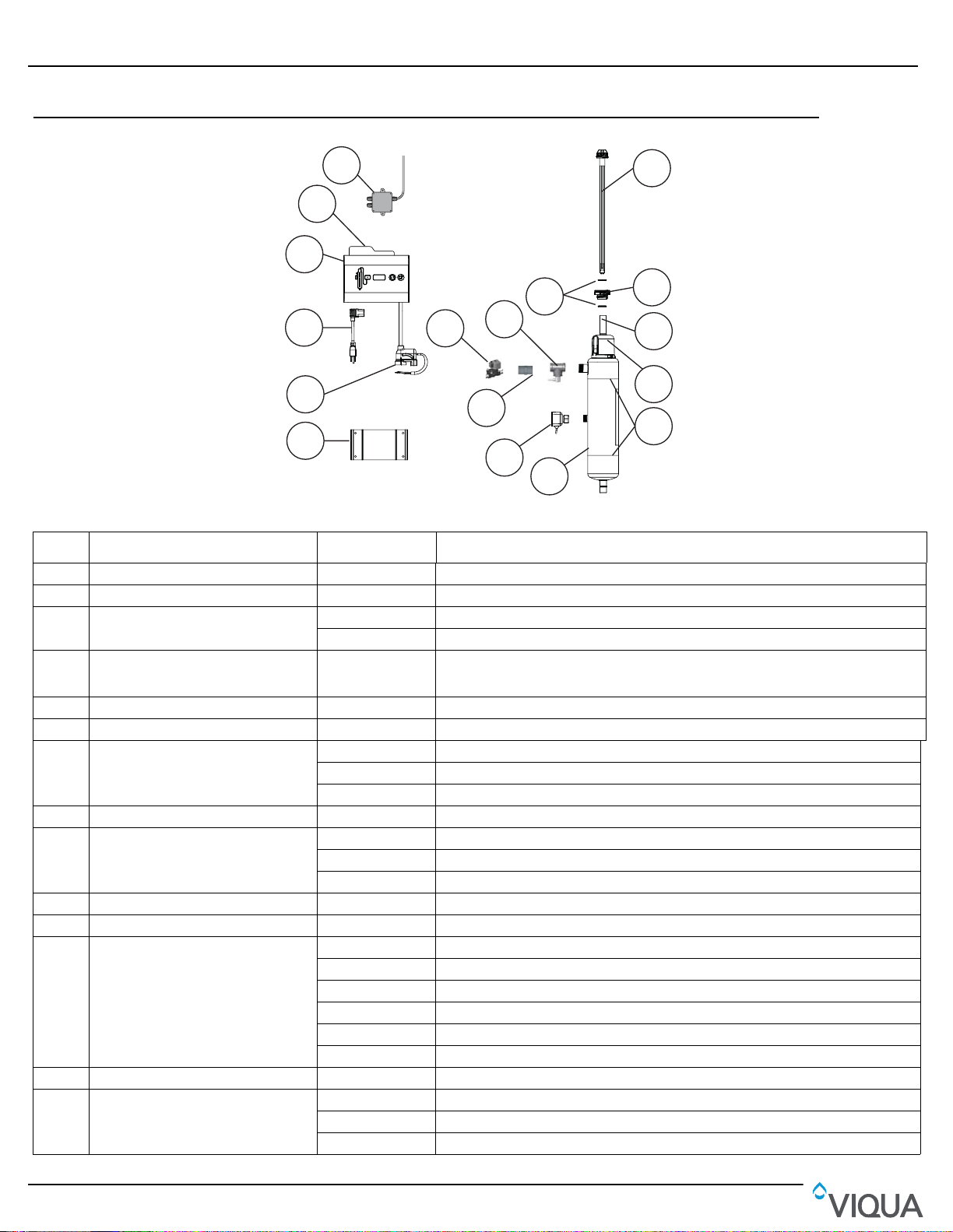
Figure 1 Model Components
Item Description Part Number UV Systems
1 Controller mounting bracket - Used for all models
2 Lamp cord - Used for all models
3Power cord
Controller (includes controller
4
mounting bracket, reference card,
safety cap, lamp cord)
5 Reference card 603069 Used for all models
6 Junction box (optional) 650705 Used for all models
7 Lamp (includes O-rings)
8 Sleeve bolt 602665 Used for all models
9 Sleeve (includes O-rings)
10 Safety cap 603000 Used for all models
11 Chamber clamp(s) - Used for all models
12 UV Chamber
13 Sensor 650703 Plus models
14 Flow Restrictor*
602636 (120V) Used for 120V models
602637 (230V) Used for 230V models
650713-007 Used for all models
602805 D4, D4+, D4-V, D4-V+
602806 E4, E4+, E4-V, E4-V+
602807 F4, F4+, F4-V, F4-V+
602732 D4, D4+, D4-V, D4-V+
602733 E4, E4+, E4-V, E4-V+
602734 F4, F4+, F4-V, F4-V+
650712-001 E4, E4-V
650712-002 E4+, E4-V+
650712-005 F4, F4-V
650712-006 F4+, F4-V
650712-013 D4, D4-V
650712-014 D4+, D4-V+
440267-R D4-V, D4-V+
440268-R E4-V, E4-V+
440269-R F4-V, F4-V+
5
Item Description Part Number UV Systems
120-240 VAC, 50-60Hz, 1A
SERIAL #: 000001
PART #: "B"
REPLACEMENT LAMP: "C"
LAMPE DE RECHANGE: "C"
DATE OF MANUFACTURE:
UV STERILIZER
98HA
MODEL
:
"A"
"SYSTEM DESCRIPTION"
425 Clair Road West,
Guelph, ON N1L 1R1 Canada
t. 519 763 1032
t.f. 1 800 265 7246
www.viqua.com
D4
100
1.2 A
UVMax D4 120v 3/4NPT
602805
602805
Solenoid valve kit (optional) (includes
15
junction box)
16 CoolTouch valve (optional)
17 O-ring 002026 Used for all models
650717-001 D4 (3/4”)
650717-002 E4, F4, F4+ (1")
650537 D4, D4+, D4-V, D4-V+ (3/4”)
650538 E4, E4+, E4-V, E4-V+, F4+(1") F4-V (1"), F4-V+ (1")
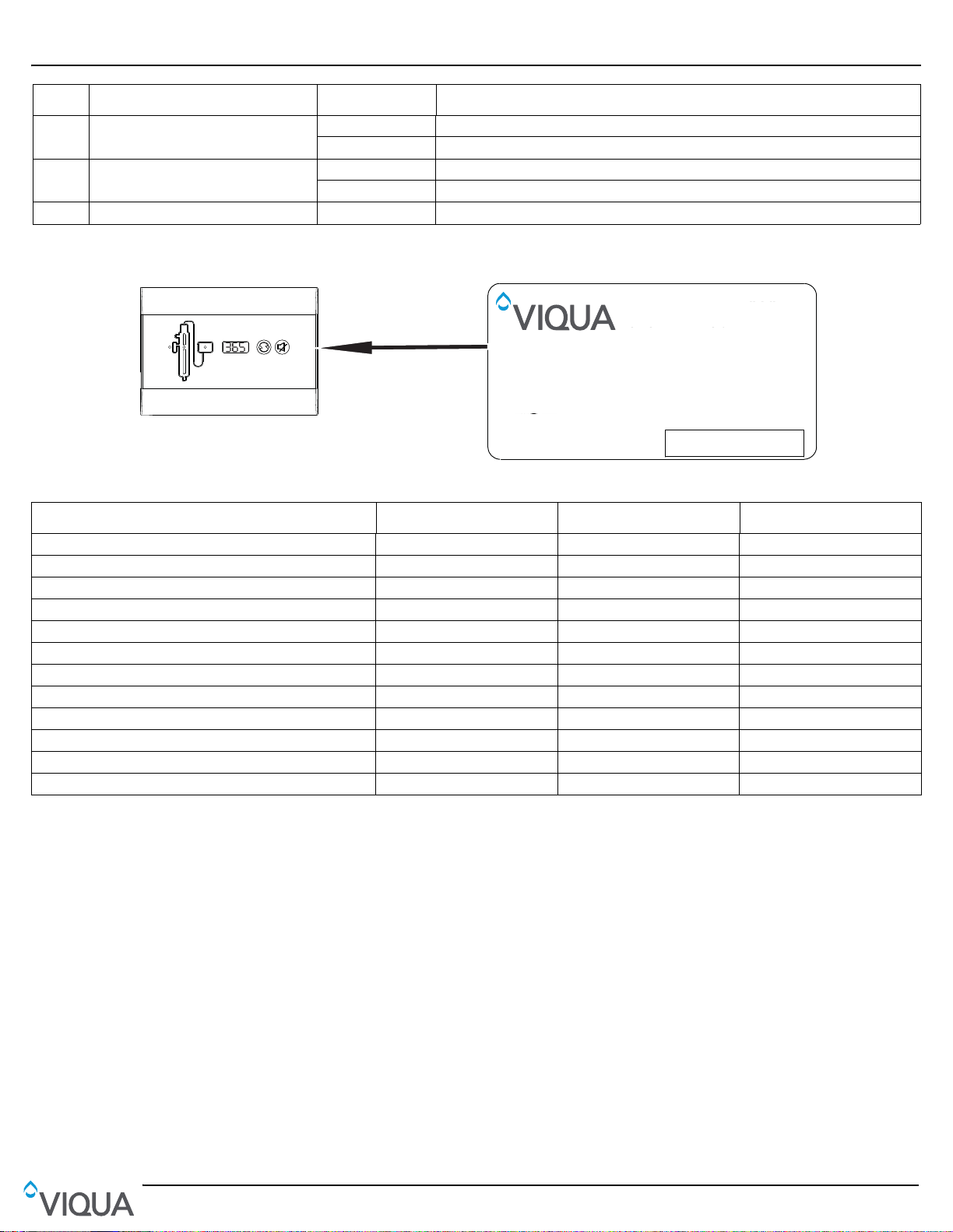
To find out what model you have, look at the label on the side of the controller as depicted below:
Figure 2 Model D/E/F- Controller Components
Operating Parameters D4/D4+/D4-V/D4-V+ E4/E4+/E4-V/E4-V+ F4/F4+/F4-V/F4-V+
No-tools maintenance Yes Yes Yes
Safety cap & special lamp plug Yes Yes Yes
Lamp operation indicator Yes Yes Yes
Controller operation indicator Yes Yes Yes
Sensor operation indicator D4+ E4+ F4+
Sensor D4+ E4+ F4+
Reference card Yes Yes Yes
Lamp timer display Yes Yes Yes
Lamp timer reset button Yes Yes Yes
Mute button Yes Yes Yes
Solenoid valve Optional Optional Optional
External control relay Optional Optional Optional
6
 Loading...