

Page 1
Manual
Viprinet Multichannel VPN Router
™
Model 1610/2610
Page 2

2
Imprint
As of 4/2010
Subject to technical changes.
Producer:
Viprinet GmbH
Mainzer Str. 43
55411 Bingen am Rhein
Germany
Phone: +49 (0)6721 4 90 30-0
Fax: +49 (0)6721 4 90 30-109
E-mail: [email protected]
Web: www.viprinet.com
© 2007-2010 Viprinet GmbH
Pictures by Frauke Boensch
Reprinting or copying even in extracts only with written permission of Viprinet GmbH.
Page 3

3
Table of contents
General information 4
Product at a glance 4
Device description 9
Technical data 10
Unpacking 10
Delivery content 11
Installation 12
Device setup 12
Installation of line modules 13
Installing the software 15
Wiring the network 16
Configuration 18
Network knowledge is necessary 18
Overview 18
Choosing topology 20
Net segmentation 22
Basic configuration using the setup program 26
Configuration using the web interface 34
Tunnel Channel Autotuning 39
Qos System and Bonding Options 43
SNMP 46
Additional information 48
Monitoring system 48
Integration of VPN Clients / Road Warriors 50
Service 51
Trouble shooting 51
Service providers 52
Appendix 54
Network basics 54
NAT-Network Address Translation 59
Page 4
4
General information
Product at a glance
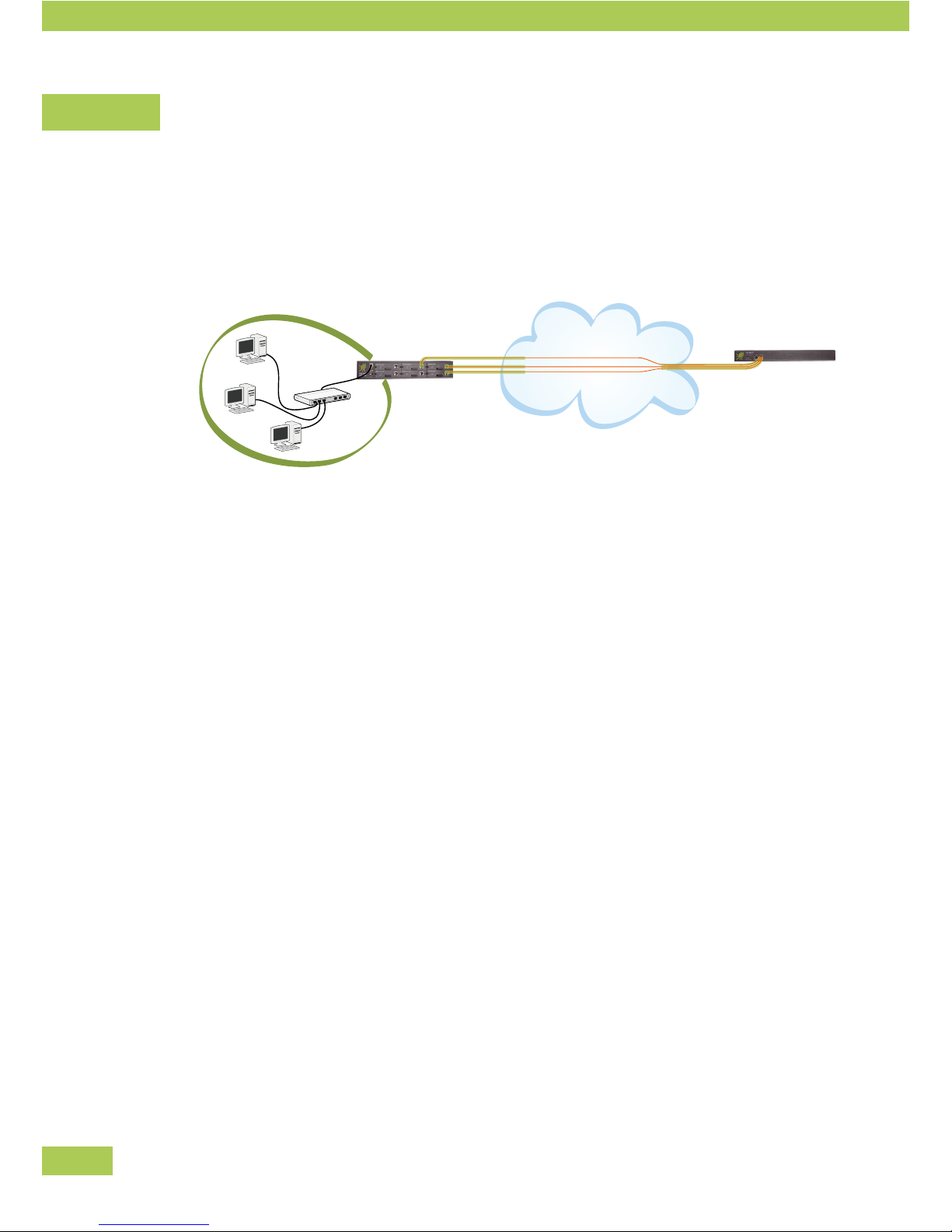
The Multichannel VPN Router connects a local network via up to six broadband channels with a Multichan-
nel VPN Hub, which is acting as a VPN concentrator. At least two Viprinet Routers are needed for this
connection:
Internet
• Left: local network with a Viprinet Multichannel VPN Router (VPN Node).
• Right: data center with Viprinet Multichannel VPN Hub (VPN Hub).
For the most common types of connections the following modems are available as modules which are
inserted into the router case.
• ADSL/ADSL2+ Annex A *
• ADSL/ADSL2+ Annex B *
• Euro-ISDN
• UMTS/HSPA/EDGE
• Fast Ethernet
External modems (e.g. WLAN, SDSL, SHDSL) may be connected using the Fast Ethernet module. All
modems that either allow PPPoE pass-through or are able to assign an IP address statically via DHCP are
supported.
Technology
The Multichannel VPN Router acts as a Layer 3 router connecting local networks at different locations on
the IP level. IP data steams are picked up by the LAN interface and are distributed to all available channels/
modem modules. As parts of data streams are sent through multiple channels, a Viprinet peer (called “VPN
Hub”) is always needed to reassemble the streams afterwards.
Preface
Page 5

5
Safety/data encryption
For each physical Internet connection, a separately encrypted VPN Tunnel (SSL protocol using 256 Bit
AES encryption) is set up between the VPN Node and the VPN Hub. These tunnels are used in a bundled
fashion, and all IP traffic is then passed through it.
Cooling
The Viprinet Router is set up for continuous operation and is cooled using regulated redundant case fans.
It is critical that the ventilation slots are never covered and the maximum specified ambient temperature is
not exceeded.
* Annex A / B
Annex A ADSL frequency range for analogue telephone connections
Annex B ADSL frequency range for ISDN telephone connections
Basics of VPN Tunnels / Terminology
VPN Hubs, VPN Nodes and VPN clients
The Multichannel VPN Router is usually used to connect one or multiple branch offices to a central location.
Generally, together all locations therefore form a star topology.
VPN Node
A router not accepting VPN connections from other routers but connecting to a cen-
tral VPN Hub is called VPN Node. VPN Nodes typically use multiple physical Internet
connections using WAN modules.
VPN Hub
A router accepting connections from VPN Nodes at a central location (data center,
company headquarters, ISP) is called VPN Hub.
VPN Clients
Single computers not located inside a network equipped with a VPN Node (e.g. Field
representatives with notebooks, home offices) may use a Software-based solution
to become part of the VPN network. These are called VPN Clients. Using the VPN
Client software, a VPN Tunnel to a VPN Hub is created.
Preface
Page 6

6
The LAN port
The router is integrated into the LAN using an Ethernet switch connected to the router's LAN port.
Using the LAN port, the web conguration system “AdminDesk” can be •
accessed from the LAN using a web browser.
Only via the LAN port, the router can be accessed by the setup software to perform the initial •
configuration.
Using the LAN port, the appropriately congured router can offer integrated services like a domain •
name server and a DHCP server to assign IP addresses to computers within the LAN.
Within the web conguration system “AdminDesk”, conguration of the LAN port is performed using the
“LAN settings” menu.
The WAN Interfaces / Module slots
The modem cards inserted into the router's module slots are called “WAN Interfaces”:
Each module used must be configured according to its type:
A DSL modem, for example, requires the PPP account data from the DSL provider.•
For dialup lines (or UMTS links) that are billed by time it might be sensible to use a configuration that •
will only dial in if a tunnel within the router is actually trying to connect to the VPN Hub.
VPN Tunnels
To connect a VPN Node with a VPN Hub, the VPN Node has to establish a TCP/IP tunnel with a VPN Hub.
The data from the VPN Node's LAN is sent via this encrypted tunnel to the VPN Hub which forwards it to
another VPN Node (that is, another location) or the Internet.
Such a logical connection between VPN Node and VPN Hub is called a “VPN Tunnel”. Within AdminDesk
this can be configured in the “VPN Tunnels” menu.
Tunnel Channels
To create such a logical VPN Tunnels, TCP/IP connections with the VPN Hub have to be established through
the ISPs used by each WAN Interface.
Thanks to its innovative channel bundling technology, the Multichannel VPN Router is able to use •
several physical lines provided by different ISPs to create such a VPN Tunnel.
Each physical connection created by a VPN Tunnel using a WAN Interface is called “Tunnel Channel”. •
A VPN Tunnel contains at least one such Tunnel Channel to make a connection possible.
Preface
Page 7

7
A Tunnel Channel contains the information which of the existing WAN Interfaces is used to create •
the physical connection.
With a VPN Node connected to just one VPN Hub (usual case) a Tunnel Channel per existing WAN Interface
will be created. On the VPN Hub things look different: All Tunnel Channels come in through one single
WAN/VPN-Port connected to the datacenter's backbone..
A VPN Node uses a Tunnel consisting of multiple Tunnel Channels, which each refer to a single WAN •
Interface, to link to the VPN Hub.
A VPN Hub connected with several branch offices (VPN Nodes) uses one Tunnel per VPN Hub, with •
each Tunnel consisting of multiple Tunnel Channels.
Traffic Classes and Rules / Quality of Service
The Multichannel VPN Router distinguishes itself by an innovative bundling procedure. This makes it pos-
sible to internally combine all Tunnel Channels used by a VPN Tunnel for certain services. The bandwidth
of all used Tunnel Channels (that is, of all physical lines of the WAN Interface) may be summed up for
individual up-/ downloads.
This bundling procedure is only sensible for certain kinds of traffic – that is, if the complete band-•
width of all Tunnel Channels should be used with a small number of connections.
This is, for example, not necessary for IP telephones (VoIP) – latency, that is the time the data needs •
to pass between VPN Node and VPN Hub, is far more important.
The Multichannel VPN Router allows you to very precisely configure how the router should deal with
certain types of data traffic. The setting how a defined group of data traffic is treated is called “QoS Traffic
Class”.
This makes it possible to set up a class for data traffic like IP telephony, always assigning it to the •
line with the smallest latency (possibly moving it to a different line as soon as that becomes the one
with the lowest latency).
For traffic needing the highest possible bandwidth, a class may be set up where all available Tunnel •
Channels are used for the data transfer.
By using the QoS classes it is also possible to guarantee or restrict the bandwidth for certain classes of
data transfers. The router makes sure that a Traffic Class with a guaranteed bandwidth will be preferred –
even if the system is running on full capacity – cutting down bandwidths of other classes to always keep
the guaranteed bandwidth available. Other classes on the other hand might be restricted to a maximum
amount of bandwidth – this way certain unimportant services like file sharing may be slowed down. QoS
Traffic Classes define how individual classes of data transfer are dealt with.
Preface
Page 8

8
The second component of the Quality of Service system are the “QoS Traffic sorting rules”. These are rules
to sort data streams by different criteria into the QoS Traffic Classes mentioned above.
Several criteria may be used to do so:
Data may be sorted by the TCP port used. A QoS Traffic sorting rule might identify all connections •
from and to Port 80 as HTTP connections. The rule would be called “HTTP”. As part of this rule, a
target class would be set – for example: the QoS Traffic Class “bundling”.
A rule might also use source and target ranges of your IP network. This way, a department may be •
identified by its IP address and sorted into a certain QoS Traffic Class that guarantees a minimum
bandwidth.
Preface
Page 9
9
Device Description
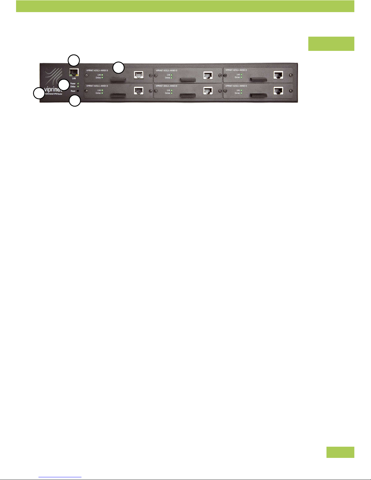
(1) IEC C14 socket for electric power (backside)
(2) LAN-socket
Link to local network
(3) Viprinet router status LEDs
Power: lit when power is supplied
Online:
lit when connection to a VPN Hub is established •
through at least one line
flashing while system is establishing connection to a VPN Hub•
(4) Reset button
The reset button can be reached with a pointed object (e.g. pencil). By pushing it briefly, the router
will restart. By continuously pushing the button for 5 seconds, the router will be reset to factory
settings. Caution: all settings will be lost! Further information for this can be found in the “service”-
chapter.
(5) Six slots for hot plug modules
Each with LEDs for status indication:
Link:
lit when cable is connected correctly•
ashing while module is trying to synchronize with ADSL-DSLAM (ADSL-module only)•
flickering when line is active•
Online:
lit when a VPN Tunnel is established with this module•
blinking when module is used to establish a VPN Tunnel•
Screws
All screws you may open are Phillip screws (e.g. screws for fixing angle-irons and module faceplates). All
other screws are Torx screws and must not be opened.
Preface
1
4
3
2
5
Page 10

10
Technical Data
Model 1610 2610
Enclosure 19" 1,5 HE 19" 1,5 HE
Measures WxHxD 435 x 66 x 320 mm 435 x 66 x 320 mm
Weight 5,1 kg 5,1 kg
Power supply input 100-240 VAC, 50-60 Hz 100-240 VAC, 50-60 Hz
Power connector IEC C14 socket IEC C14 socket
Number of fans / controlled / monitored
2 / ü / - 2 / ü / -
LAN interface GBit Ethernet GBit Ethernet
WAN module slots 6 6
Maximum input wattage 70 Watt 75 Watt
Typical wattage 40 Watt 45 Watt
SNMP Status / Accounting
ü / « ü / ü
Bonding capacity MBit /s 125 200
Unpacking
The Viprinet Router and the modules will be sent singly or pre-configured depending on the supplier.
Unpack all elements and check if complete.
Preface
Page 11
11
Delivery content
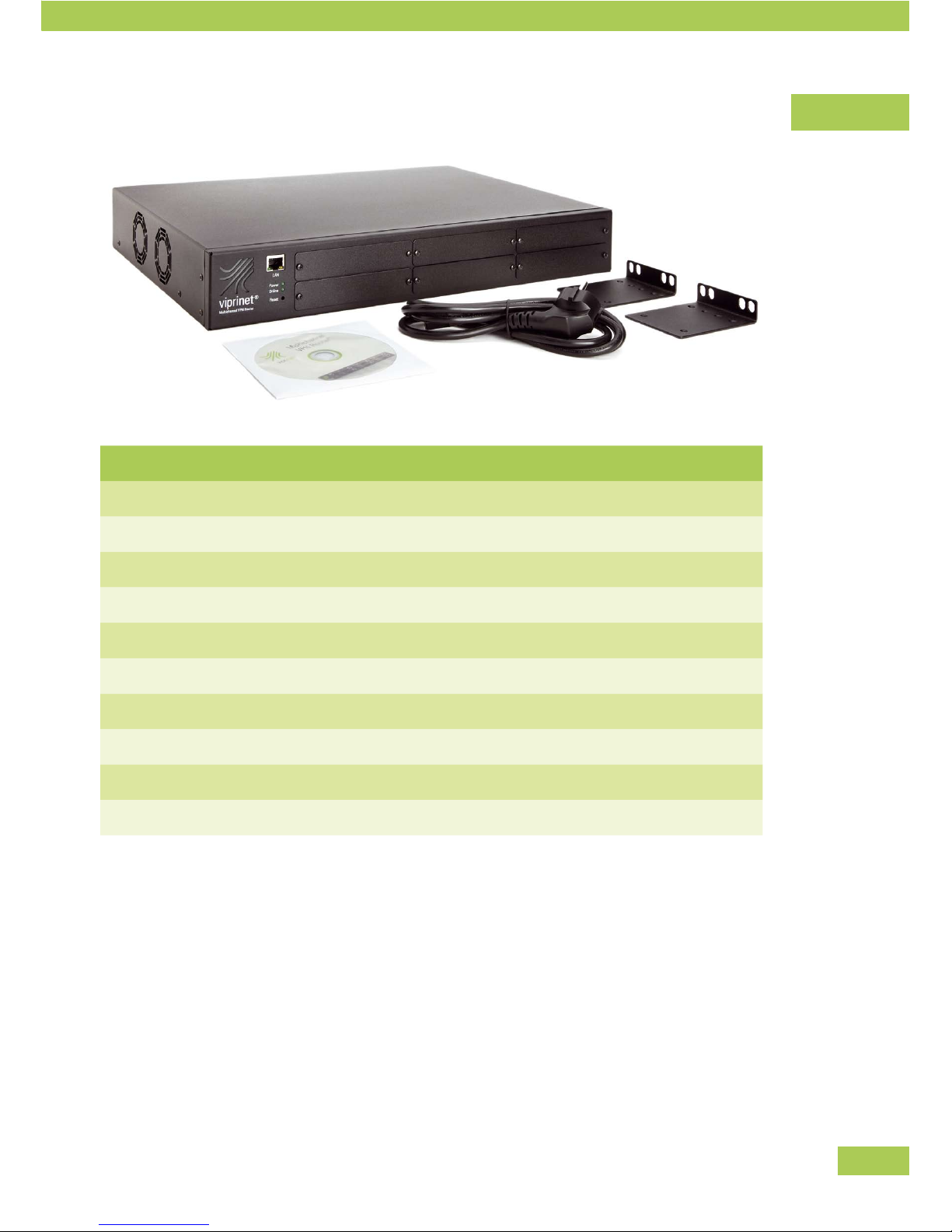
Number Type
1 Multichannel VPN Router (model number see identification plate on the backside)
1 Power Cable
1 Manual
1 CD with software
2 Angle-irons for inserting router into 19” rack
* ADSL/ADSL2+ module Annex A
* ADSL/ADSL2+ module Annex B
* Euro-ISDN module
* Fast Ethernet module
* UMTS/GPRS/EDGE module
* Number of modules due to your order. See delivery note.
Preface
Page 12
12
Installation
Device setup
The Viprinet Router is a desktop device and can be put up at any location which offers the following
conditions:
Working temperature 10-35°C•
No direct sunlight (danger of overheating)•
Detached position•
Attention:
The ventilation shafts must not be covered. There must be at least a space of 5cm on both sides of the
device to assure proper ventilation to prevent overheating.
Installation into 19" rack
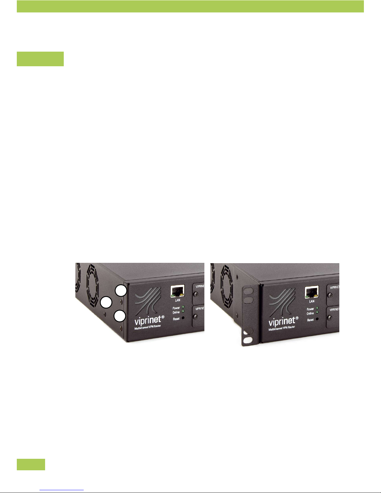
If necessary, the Viprinet Router can be mounted into a 19” rack. Angle-irons are included in the delivery.
Mounting of Angle-irons
• Unscrew the three Phillips screws left and right (1)-(3).
• Attach the angle-irons to both sides with these screws.
• The Viprinet Router can now be inserted into a 19” rack.
Installation
3
2
1
Page 13

13
Installation of line modules
Up to 6 line modules can be inserted into the Viprinet Router. Modules can be plugged into any of the slots.
They may be installed or taken out even when the router is running (hot-plug).
If modules are reassembled, the configuration has to be changed (see below).
Unscrew both screws.•
Take off the cover (resp. pull out the module).•
Insert the chosen module into the slot. •
Keep in mind to put the board straight into the rails.
Put the screws back in.•
The module has to be configured. •
First configuration: use the setup program or the Web Interface.
For any upgrade: use the Web Interface.
Numbering of modules
All module slots are numbered internally. The configuration is saved for each slot.
Installation
3
6
2
5
1
4
Page 14

14
Replacement of modules
You can exchange a module in slot 1 with another one of the same type.•
The configuration is maintained. •
This way, you can, for example, exchange one ADSL module with another ADSL module. Slot and
configuration stay the same.
If extracting a configured module and replacing it with a different type, the previous configuration of •
the slot is lost.
ADSL Annex A and B are seen as the same type of module.•
Installation
Page 15

15
Installing the software
The following software is delivered with the Viprinet Router and should be installed on a workstation/
desktop.
Setup program
Setup program for configuring the Viprinet router.
File name: setup.exe
Monitoring system
Monitoring system displaying of the data streams.
Setup file name: monitor.exe
Installation of the setup program
There is no need to install the setup program. The exe-file can be executed immediately
Copy the exe-file to your desktop or execute directly from CD.•
Installation of Monitoring system
You can install the Monitoring system on your desktop.
Insert CD.•
Start monitor.exe from CD.•
Follow instructions on screen.•
Installation
Page 16
16
Wiring the network
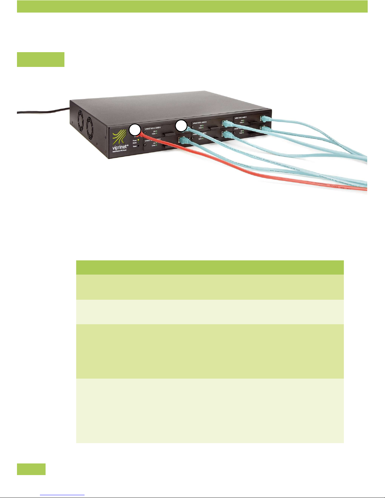
Connect the Viprinet Router with the network and the lines as follows:
Connect the LAN port (1) with the local network,•
e.g. a work-group switch•
e.g. a firewall system •
Connect the module with the lines. Notice the following tips.•
Module Type
ADSL /ADSL2+ module Annex A
Network cable (if necessary shielded) (CAT5)
Connect with splitter, “DSL” socket
ADSL /ADSL2+ module Annex B
Network cable (if necessary shielded) (CAT5)
Connect with splitter, “DSL” socket
Euro-ISDN module
ISDN cable with RJ-14 plug or network cable (if necessary
shielded) (CAT5)
Connect with NTBA
(Alternatively, you can also connect to ISDN bus of a tele-
phone system installation, e.g. “s0 intern”)
Fast Ethernet module
Network cable (if necessary shielded) (CAT5)
Connect with Ethernet socket of a router or modem, e.g.:
cable modem•
SDSL modem•
radio link •
leased line router•
Installation
2
1
Page 17

17
Module Type
UMTS/GPRS/EDGE-Module
Mount the UMTS antenna shipped with the module to the
SMA socket. Alternatively an external UMTS antenna
equipped with an SMA plug may be connected.
Installation
Page 18

18
Configuration
Network knowledge is necessary
For correct Viprinet Router configuration sufficient network knowledge is necessary. You will find an over-
view of important terms in the appendix. See: Basic Network Technology.
Overview
Below you will find a compact overview about the steps you need to take in order to use the router inside
your network:
Step Action
Define topology
You should first decide on a network topology. As a rule, it should
be established in a star topology – one or more VPN Nodes con-
nected to one central VPN Hub forwarding to the Internet and
routing between the VPN Nodes.
Net segmentation
Since the Viprinet Router is active as a Layer 3 router, the
networks which are to be connected have to have their own IP sub-
nets. So you will have to segment your entire IP network consisting
of private and public IP ranges. The Viprinet Router working as a
VPN Hub will route between those subnets.
Get public IPs
You need public IPs for the following devices:
VPN Hub •
1. an IP for the Uplink/LAN port (routing towards the Internet
is done from here; connections from the VPN using private IP
addresses are converted to this IP address using NAT.)
2. an IP address for the WAN/VPN interface (may use same
IP subnet as the LAN port)
for all VPN Nodes •
1. An IP address for each module (typically dynamic IP
addresses, automatically assigned by service provider, are
used here though)
Configuration
Page 19

19
Basic configuration
(Setup program)
At first use, you will have to install a basic configuration on each
Viprinet Router using the setup program.
The following values are determined:
router name•
local IP and netmask•
VPN Node/ VPN Hub•
LAN Interface settings•
module configuration•
VPN connection configuration•
router password •
If needed, sophisticated
configuration
(Web Interface)
If required, you can set up further congurations by using the Web
Interface. Here, the values of the basic configuration can be changed
and further parameters can be added like:
all LAN and module settings•
Tunnel and Channel settings•
bandwidth management (priority settings for certain data •
streams)
user rights •
Configuration
Page 20
20
Choosing topology
Example: One office with bundled redundant connection to the Internet
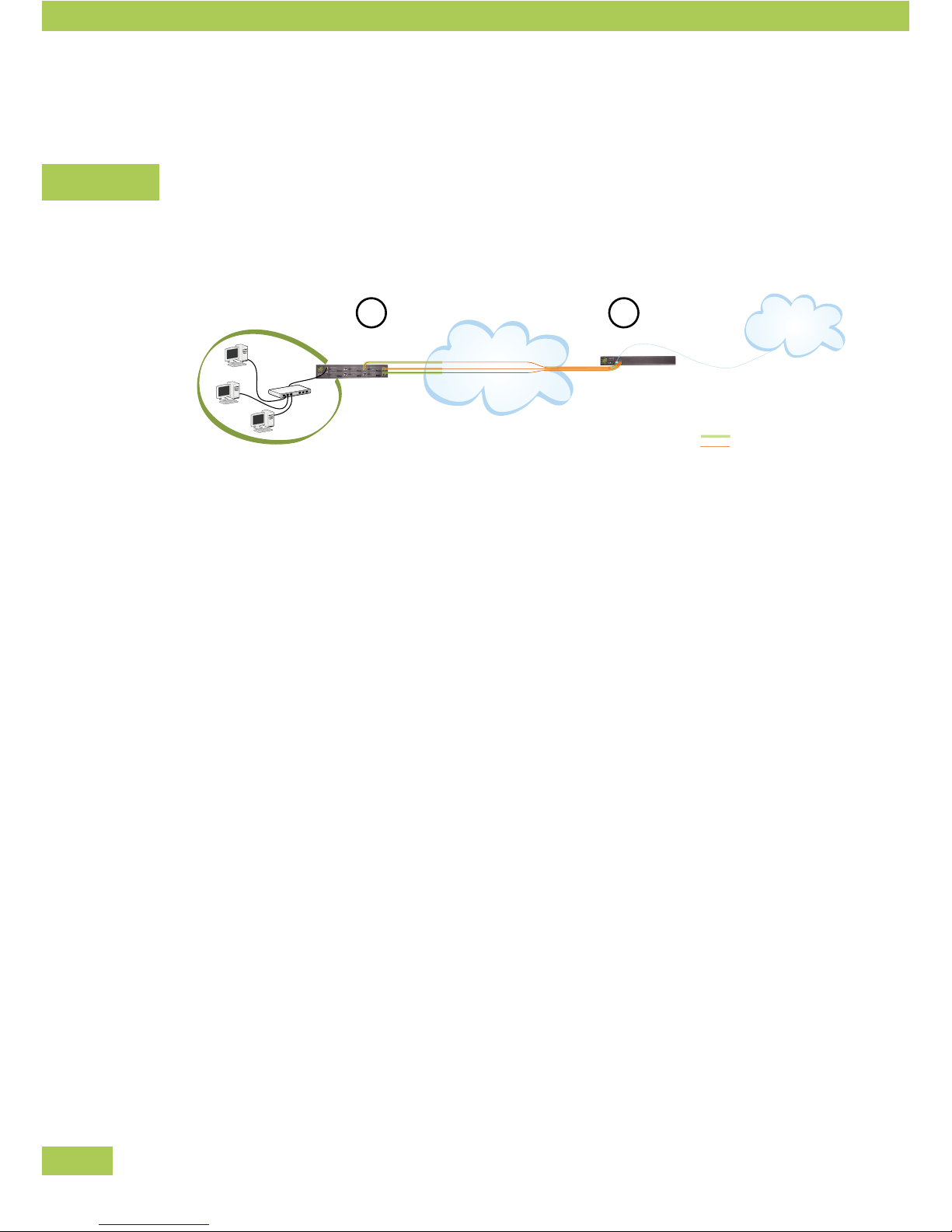
A bundled redundant connection of a single office to the internet may be established using two Viprinet
Routers. Up to six access lines in any combination can be used at the office.
Internet
Internet
Branch Office (VPN Node) Data Center (VPN Hub)
Physical Line
Logical Connection
1
2
(1) Data center (VPN Hub)
The router in the data center should be connected to the Internet via two Ethernet connections to the
datacenter's backbone. The LAN port of the router serves as an uplink for trafc which is transmitted
from the VPN towards the Internet. The encrypted VPN connections from the VPN Node arrive via
the WAN/VPN port.
The WAN/VPN port needs to get a static public IP address assigned, which is used by the VPN
Nodes as destination address for establishing VPN Tunnel Channels. The Uplink/LAN port commonly
also gets assigned a public IP address. Should the VPN Hub be placed inside a closed Intranet with
out any connection to the Internet, a private IP address may be used here instead.
(2) Branch office (VPN Node)
The router here can be equipped with various different modules. Via each of these modules plus the
Internet backbone of the provider an encrypted VPN connection is established (a “Tunnel Channel”)
to the Ethernet module of the VPN Hub.
The LAN of the branch ofce is connected to the LAN port of the Viprinet Router.
As the “Tunnel Channel” connections are outgoing TCP connections, a static public IP is not required
for the VPN Node's WAN modules, dynamically assigned IP addresses are OK, too. It is even possible
to use private IP addresses if a device behind the module (e.g. a xed line router or a DSL router)
replaces the source IP address of outgoing TCP connections by a public one using Network Address
Translation (NAT).
The ofce LAN (e.g. an Ethernet switch) is connected to the Viprinet Router using the LAN port.
Configuration
Page 21
21
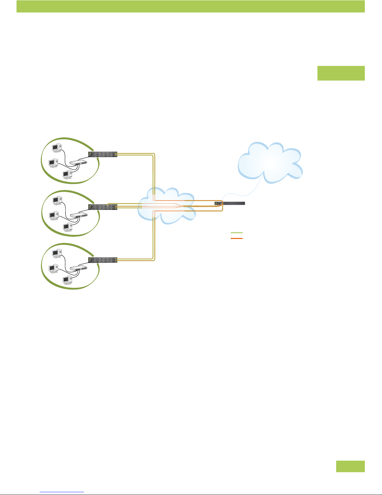
Example: Several branch offices (Subnets in star topology)
Should several branch offices be connected to the data center, a star topology is normally used – several
VPN Nodes are connected to one VPN Hub in the “center” which serves as a data distributor between the
branch offices themselves and the Internet.
All “Tunnel Channels” of all branch offices connect to a single WAN/ VPN port at the VPN Hub. The only
limiting factor is the total bandwidth and bonding capacity available at this VPN Hub.
(1) Data center (VPN Hub)
For the router in the data center, the Uplink/LAN port is used as gateway to the public
internet, while VPN Tunnel traffic is handled encrypted on the WAN/ VPN port.
(2-4) Branch offices (VPN Nodes)
The branch routers may be equipped with different modules, e.g. 2 ADSL or 3 ADSL2+ or 1 ADSL and
1 WLAN. An encrypted VPN connection (a Tunnel Channel) using these modules and the backbone
of the service provider is build between the VPN Node and the WAN/ VPN port of the VPN Hub. The
branches LAN is connected to the L AN port of the Viprinet Router.
For this type of topology, it is of vital importance that the VPN Hub can be reached easily by all physical
service providers of the VPN Nodes. Therefore, if the VPN Hub is used across country borders, it should be
set up in the “center“.
Configuration
Branch office (VPN Node) Data center (VPN Hub)
e.g. 1× ADSL + 1× WLAN
Internet
Internet
e.g. 3× ADSL2+
e.g. 2× ADSL
Physical Line
Logical Connection
Page 22

22
To do so:
Set up the VPN Hub at a data center directly connected to a provider backbone or at an national IP •
exchange point.
When using the VPN Hub at the company headquarters, this should have a fail safe and broadband •
Internet connection which is itself not based on a Viprinet bundling.
Further possibilities
Alternative topologies like ring- or peer-to-peer-structures are also possible, but should only be configured
by experienced experts. The respective configuration can only be done via the Web Interface.
It is another special case if two branch offices are meant to be connected directly using multiple bundled
broadband lines on both sides. The Viprinet Router is able to support this, but it may prove to be quite dif-
cult – Tunnel Channels from the first branch office have to connect to varied lines at the other branch office.
This does not present such a big problem if both branch offices are using the same amount of symmetrical
lines. If a different number of lines or asymmetrical lines (in this case, the upstream of the second branch
office has to be as high as the downstream of the first branch office) are in use, it is definitely not advisable
to use this topology. In this case, a star topology with a VPN Hub at an external data center should be
used. In any case, one of the two branch offices (the one where the router is declared VPN Hub) needs to
have static IP addresses assigned on all WAN modules so the router in the other office is able to setup the
Tunnel Channel connections.
Net segmentation
Since the Viprinet Router is active as a Layer 3 router, the networks to be connected have to have their own
IP subnets. You have to segment your entire IP network which is made up of private and/or public IP ranges;
each subnet has to have its own IP range. Between these networks, the Viprinet Router serves as a router.
Configuration
Page 23
23
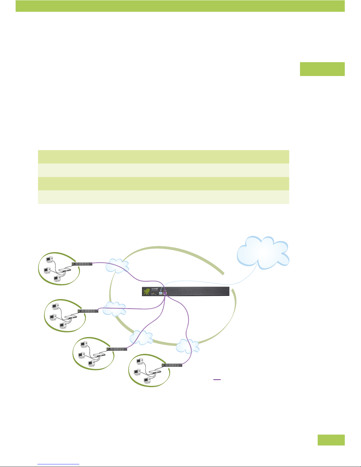
Configuration with private IPs
You can build your network using private IP addresses. These are only valid inside your own network and
therefore not reachable from the Internet. If data should leave the VPN towards the Internet, the VPN Hub
within the VPN will have to mask the private IP source addresses using Network Address Translation (NAT)
for packets leaving the VPN towards the Internet.
Segmenting the net
Divide your net into branches, e.g. with a supposed network of 10.0/16 (In CIDR notation, description see
appendix).
Branch 1 10.0.1/24
Branch 2 10.0.2/24
Branch 3 10.0.3/24
Branch 4 10.0.4/24
Configuration
Internet
Data center
Bundled logical connection
(VPN Tunnel)
10.0.4/24
10.0.3/24
10.0.2/24
10.0.1/24
Page 24
24
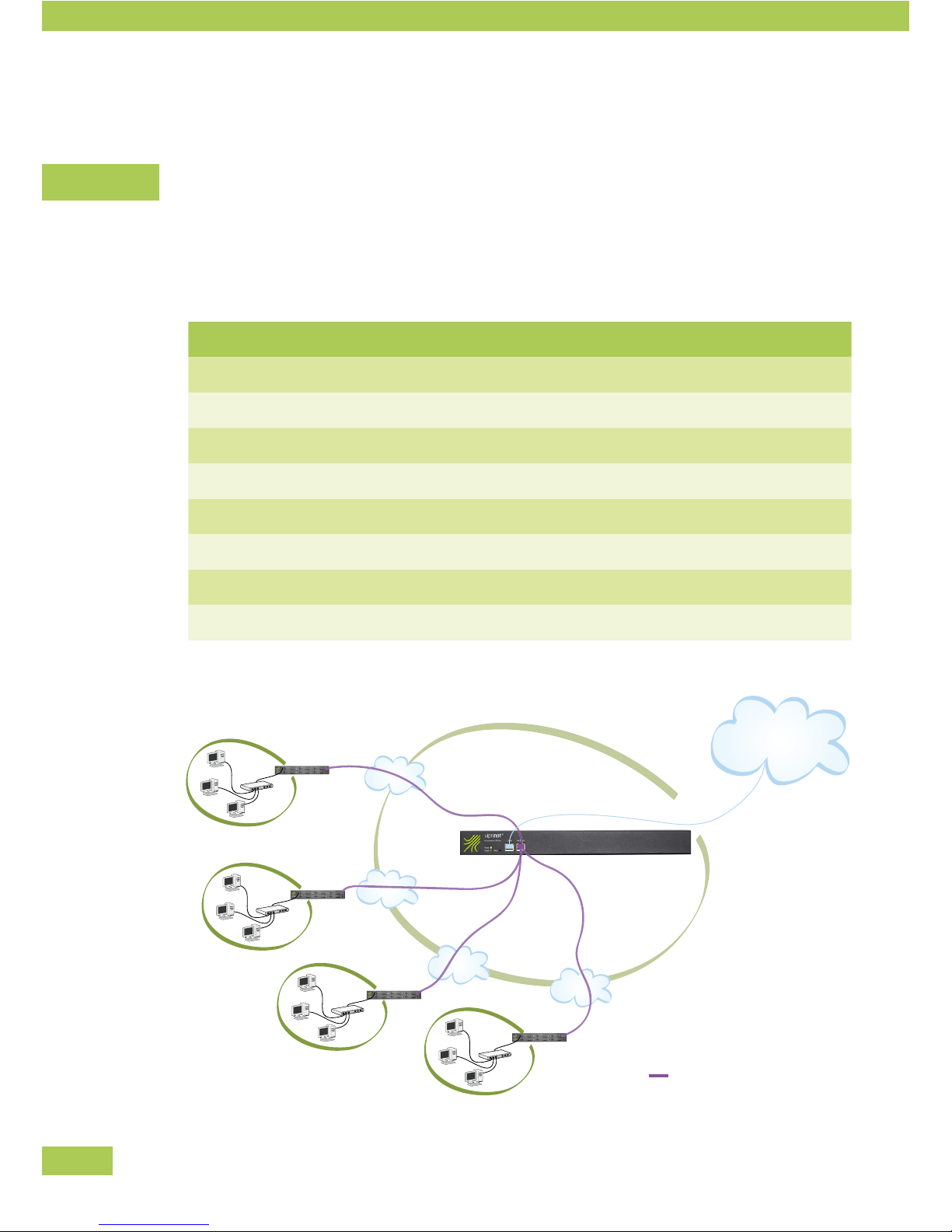
Configuration with public IPs
Since public IP addresses are limited, you have to be sparing when segmenting a public IP net – the single
segments should only be as big as really needed for each branch office.
Net segmentation
You may have the IP range 192.0.2.0/24 assigned for your network. Subdivide your network:
into two branches into four branches into eight branches
Branch 1 192.0.2.0/25 192.0.2.0/26 192.0.2.0/27
Branch 2 192.0.2.128/25 192.0.2.64/26 192.0.2.32/27
Branch 3 192.0.2.128/26 192.0.2.64/27
Branch 4 192.0.2.192/26 192.0.2.96/27
Branch 5 192.0.2.128/27
Branch 6 192.0.2.160/27
Branch 7 192.0.2.192/27
Branch 8 192.0.2.224/27
Configuration
Internet
192.0.2.192/26
192.0.2.128/26
192.0.2.64/26
192.0.2.0/26
Data center
Bundled logical connection
(VPN Tunnel)
Page 25

25
Configuration with private and public IPs
If you have set up your network with private IPs, but want to use computers with public IPs as well (e.g.
server reachable via the Internet), you should start with the initial configuration for private IP networks in
the setup program. Afterwards, you can insert the public IP addresses (using CIDR notation) via the Web
Interface at
AdminDesk » WAN/VPN Routing and NAT » WAN/VPN routing rules
Routing decisions are based on a set of rules. If a public IP block gets routed by your datacenter ISP to your
VPN Hub, and you wish to forward this or parts of this block to one or more branch offices (VPN Nodes), you
will have to create routing rules for that. Assumed you wish to route the public IP network 192.0.2.64/27
through the VPN to a VPN Node, you have to create a rule on the VPN Hub using Add a routing rule. Give
the rule a name (e.g. “Public network branch 1“). Inside the rule object set Matching IP Protocols to Ignore
(all IP protocols are to be routed), How to match IP addresses to Destination (routing decisions are based on
the target IP address of incoming packets). For IP Addresses enter 192.0.2.64/27. Finally select which VPN
Node this should be routed to by choosing its VPN tunnel under Target Interface.
Configuration
Page 26
26
Basic configuration using the setup program
Before using a new router, you have to install a basic configuration on your new Viprinet Router using the
setup program. The setup program is compatible with Windows 2000/XP/Vista/7. The chosen settings may
be refined and adjusted with the Web Interface later.
This basic configuration has to be carried out before putting the router into use.•
Each router is set up separately with all its modules. The modules are queried one after the other. •
Each type of module requires different specications.
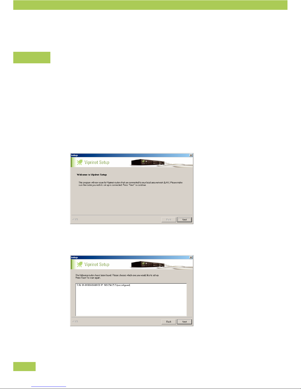
Starting the Setup Program
Make sure your PC is connected with the router by the LAN or directly via a crossover cable at the •
LAN port.
Start up the Setup Program directly from CD or your hard drive. •
File name: Setup.exe
Confirm with “Next”•
The program searches for all available Viprinet Routers inside the local network. This is done using IP •
broadcasts, so only routers inside the same broadcast segment are detected.
All Viprinet Router found are displayed.•
Mark the Viprinet Router you would like to configure.•
Confirm with “Next”.•
Configuration
Page 27
27
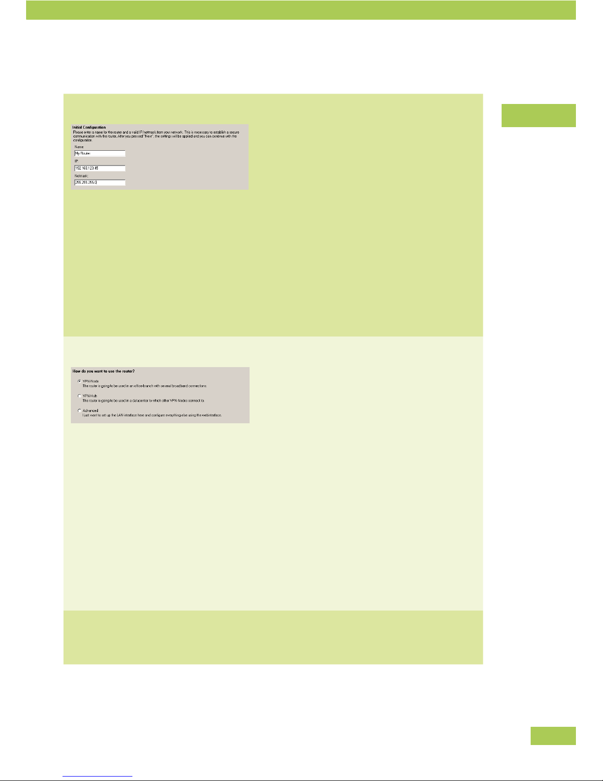
Basic Configuration
Initial configuration Enter the following data:
Name •
You can identify the router by this name later on (it is
displayed when opening the setup program and the
Web Interface).
IP •
Local IP for the LAN where the router is situ-
ated.
Netmask •
Netmask of the LAN.
How would you like to use the router?
Decide on how you are going to use the router.
VPN-Node •
Router at a branch office. Connected to a
VPN Hub through the Internet via one or more
broadband lines.
VPN-Hub •
Router at data center
(This configuration is only possible if solely
Ethernet modules are used.)
Advanced •
If you chose this setting, only the LAN-Interface
is configured; all other settings may be done via
the Web Interface later on.
Continue Continue depending on your choice, read on the next
pages.
Configuration
Page 28
28
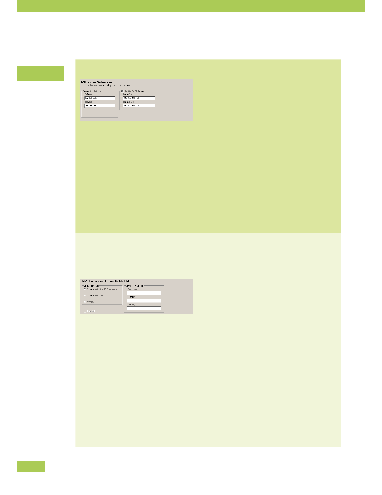
If "VPN Node" was chosen
LAN-Interface Configuration IP-Address •
Enter the IP address here under which the
router may be reached in the LAN. The address
serves as a gateway for computers within the
LAN.
Netmask corresponding to the IP entered above. •
Enable DHCP-Server •
Tick this box if the router should assign IPs
dynamically within the LAN.
Range Start/ Range Stop •
Enter the IP address range the router should
assign to computers inside the LAN via DHCP.
Enter the first and the last assignable address.
Module configuration
The modules in each slot are queried one after the
other (up to six). Each type of module requires differ-
ent specifications.
Ethernet module
Ethernet with fixed IP & Gateway •
Configure the Ethernet module using a fixed IP
address, netmask and gateway (e.g. when con-
necting a leased line router or a modem to the
Ethernet module)
Ethernet with DHCP •
As above, but the Ethernet module gets its IP
configuration from the DHCP server of the con-
nected router or modem.
PPPoE •
A PPPoE-enabled modem is connected to the
Ethernet module (e.g. SDSL); enter username
and password for PPP access.
Configuration
Page 29
29
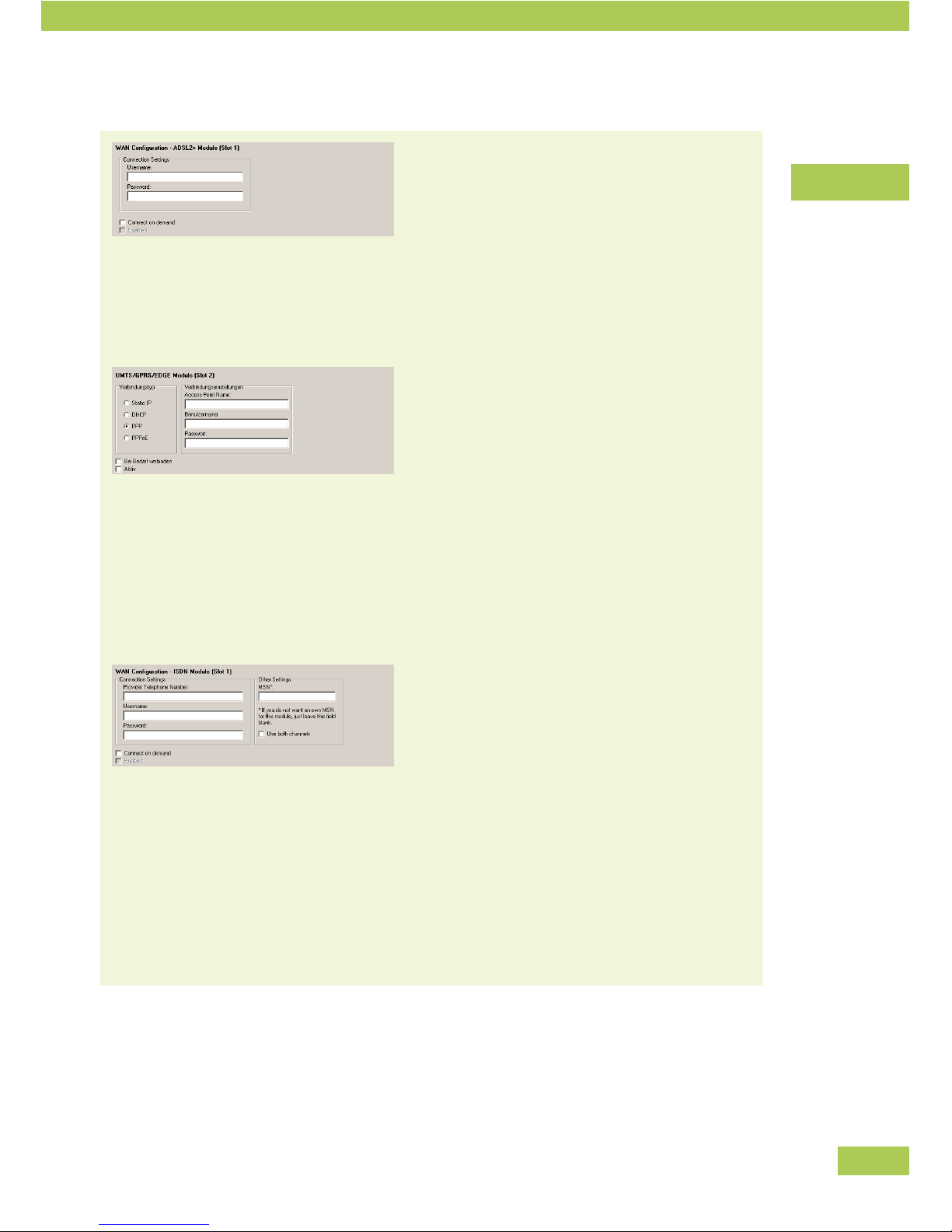
ADSL module
Username and password •
Enter ISP's PPP username and password.
Connect on demand •
If this option is activated, the module only dials
in if a VPN Tunnel is actually trying to use this
line. This makes sense if the connection is
deducted on a time basis.
UMTS module
Access Point Name •
Enter the APN as specified by the UMTS
provider.
User name and password •
Enter the account name and password as given
by the UMTS provider. For many providers these
values may be freely chosen, the fields however
must be filled.
Connect on demand •
(See ADSL module)
ISDN module
Username and password •
Enter service provider's PPP username and
password.
Provider Telephone Number•
MSN •
Your own ISDN identification number (optional)
Use both channels •
ISDN provides two data channels. When using
both, the capacity is 128Kbit/s, otherwise
64Kbit/s.
Connect on demand •
(See ADSL module)
Configuration
Page 30
30
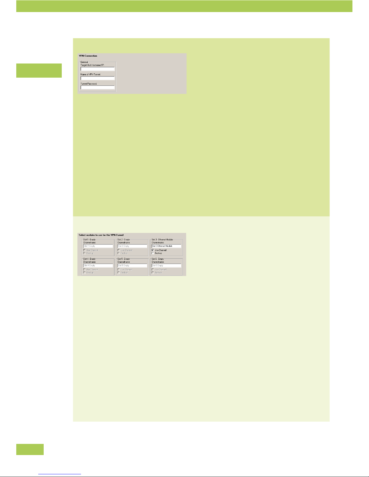
VPN-Connection
Here, the connection to the VPN Hub (= router at the
data center) is configured.
Target Hub Hostname/IP •
Enter the host name or the IP of the Ethernet
module of the VPN Hub to connect to.
• Name of VPN-Tunnel
This name identifies the link of between the
VPN Hub and this VPN Node. Use the same
unique name as used for this link on the VPN
Hub.
Tunnel Password •
The password needs to be identical to the one
configured at the VPN Hub for this tunnel.
Modules to be used
Now, you decide which of the installed modules are
used for connections (VPN Tunnel Channels) to the
VPN Hub – in most cases, you will use all existing
modules.
Channelname •
The freely chosen name also has to be entered
in the VPN Hub.
Use channel •
Decides if this module is used. If activated, the
VPN Tunnel will try to establish a Channel using
this module after power-up.
Backup •
Decides whether this module is a fixed line or
a backup line. Backup lines are only brought up
if a configured minimum of lines are no longer
online. ISDN lines and UMTS links deducted on
a time basis are usually configured as backup
lines.
Configuration
Page 31
31
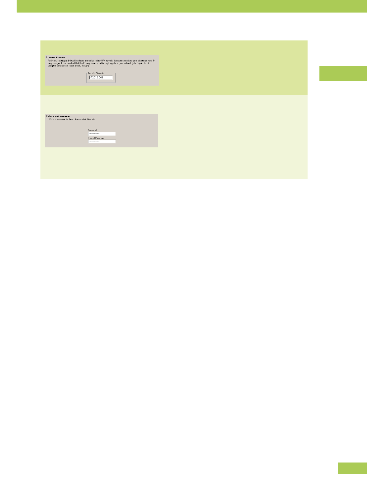
Transfer Network
A private IP network not used anywhere else in-•
side the VPN is needed internally by the router.
Root password
You have to decide on a router root password.
The password is for the user “root” (who has •
all rights).
Use a safe password (more than 8 characters, a •
mixture of capital and small letters and digits).
Write down the password and keep it safe.•
Configuration
Page 32
32
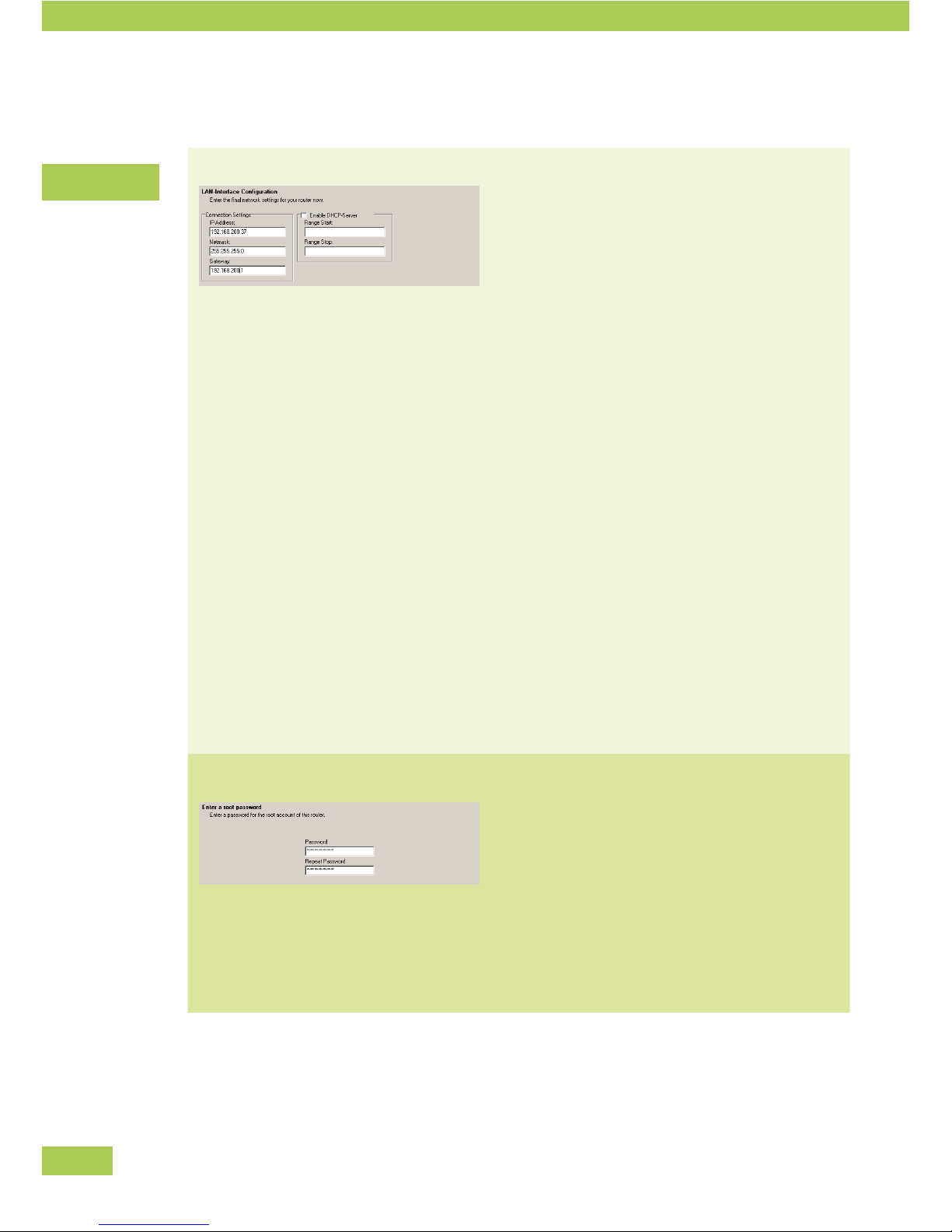
If Advanced was chosen
LAN Interface Configuration IP address •
If the router is to be used as a VPN Hub later,
only a static public IP is sensible here. If the
router is used as a VPN Node later on, a private
IP address may also be used. This is used by the
LAN as a gateway.
Netmask •
Enter the corresponding netmask.
Gateway •
For a VPN Hub, enter the IP of the gateway.
For a VPN Node, the router itself will be the
gateway, the field will therefore stay clear.
DHCP server •
Tick this option, if the Viprinet Router should
assign IPs dynamically inside the LAN. This is
only sensible for VPN Nodes,
Range start/ range stop •
Enter the IP address range that should be as-
signed per DHCP by the Viprinet Router.
Root password
You have to decide on a router password.
The password is for the user “root” (who has •
all rights).
Use a safe password (more than 8 characters, a •
mixture of capital and small letters and digits).
Write down the password and keep it safe.•
Configuration
Page 33
33
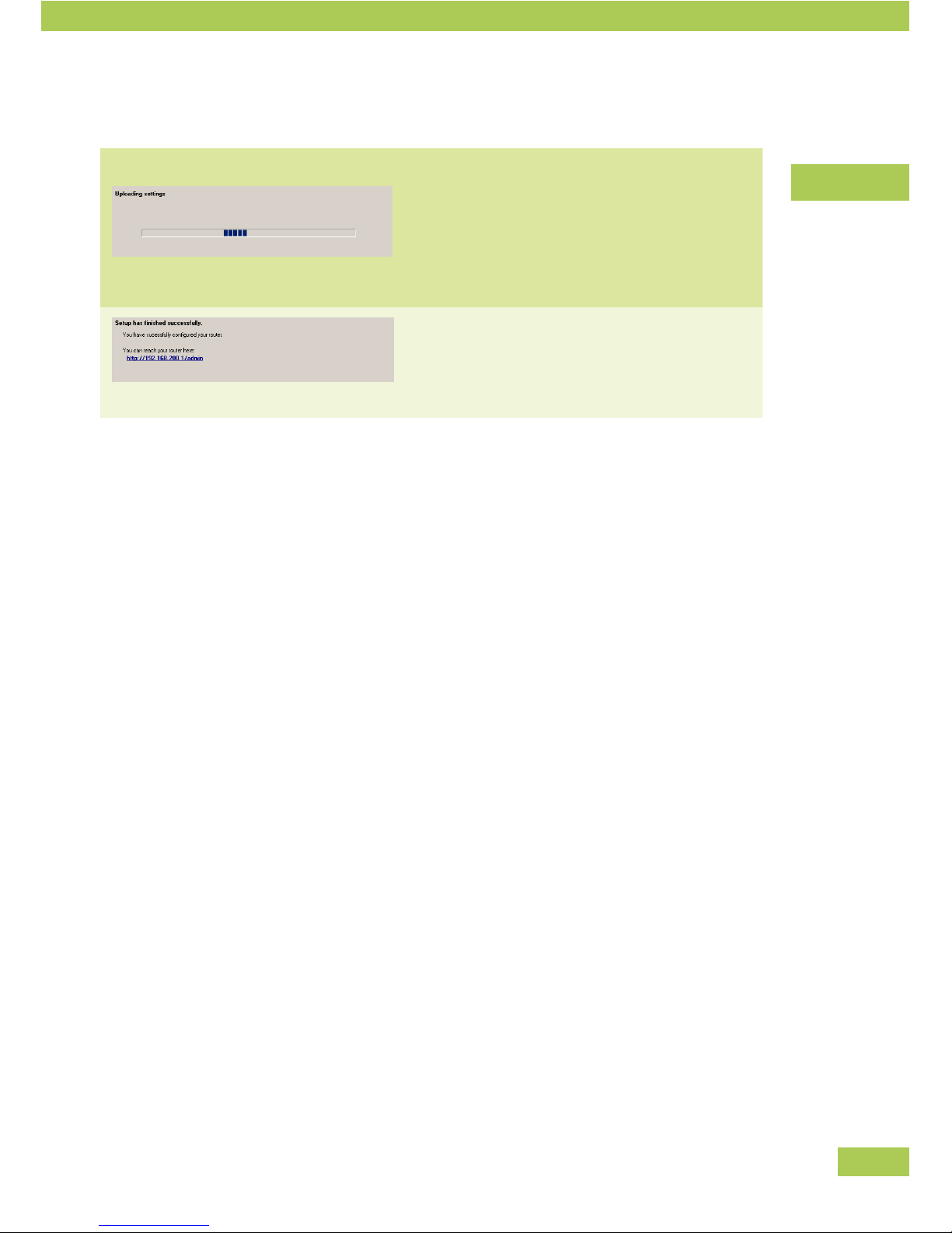
Finish the configuration
Upload settings When all steps in the setup program are done, you
can upload them to your router.
Click “Finish”.•
The configuration is uploaded to the router.•
The URL of the router's Web Interface is shown
Configuration
Page 34
34
Configuration using the web interface
The Viprinet Router implements a Web Interface which allows you to carry out all settings. The Web Inter-
face can only be used if the initial configuration using the setup program has been done.
You will find a description of the use of the Web Interface here. Depending on the software status, your
Web Interface may look different and offer other possibilities. The basic use will be identical though.
Examples and operating logic of the web interface
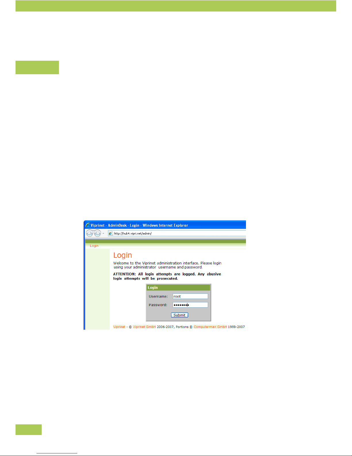
Opening the Web Interface
You can access each Viprinet Router via its IP address assigned to its LAN Interface.
Start your web browser.
Enter the URL of the Viprinet Router you want to congure, e.g. http://192.0.2.1 •
The login mask appears.•
Enter username and password. •
Standard user: root.
The password was set during the first configuration with the setup program.
Configuration
Page 35
35
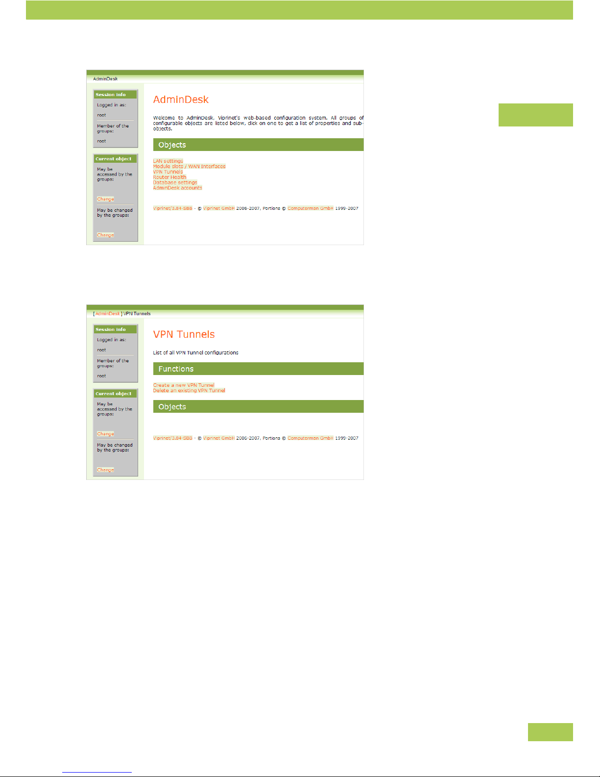
You see the main menu with all available objects.•
Select an object, e.g. “VPN Tunnels”.•
You see the functions and objects now.•
Navigate
In addition, you see your selected path top-left on each screen. •
Click on a part of the path to change to another level, if necessary.
Select a function, an object or a feature, if necessary.•
Configuration
Page 36

36
Configuration options
Below you will find a brief introduction of the main configuration objects inside the Web Interface. Detailed
information about these objects is available inside the Web Interface. It is possible that your Viprinet
Router is already supplied with a newer software version with more possibilities. You will then have an
extended menu available.
Information about the current version and its possibilities can also be found on the Internet at:
http://www.viprinet.com
LAN settings
LAN Interface settings including the settings of the integrated DHCP
server are configured with this object.
Module slots / WAN
interfaces
Allows you to configure the modules (e.g. ISP account data) for each
module slot.
VPN Tunnels
VPN Tunnels, that is Site-to-Site links between a VPN Hub and VPN
Nodes are configured here. A VPN Tunnel is the logical link between
two routers. The physical connection consists of several Tunnel Chan-
nels which themselves are referring to one installed module each.
» Bandwidth-
management
The bandwidth summed up from the Tunnel Channels of a VPN Tunnel is
initially seen as a unit within the Viprinet Router.
From these capacities you can assign shares to single depart-•
ments or services at a branch office using the integrated band-
width management.
It is, for example, possible to assign a guaranteed minimal band-•
width to defined services and to slow down others.
Suitable rules can be set up on the basis of numerous data •
sources like IP net ranges, port numbers or package qualities.
Configuration
Page 37

37
» Bandwidth-
management
(continued)
You can carry out the assessments through the following steps:
Traffic Classes are created. •
E.g. E-mails, Web traffic, IP telephoning
Path: AdminDesk » VPN Tunnels » My Tunnel » QoS Traffic
classes » Add a traffic class
For each Traffic Class, features are set. e.g.: •
- Minimum guaranteed bandwidth
- Maximum allowed bandwidth
- Priority of channel latency
Rules are defined about which criteria are used to sort new con-•
nections into one of the existing Traffic Classes. Therefore, these
rules refer to fitting Traffic Classes.
Path: AdminDesk » VPN Tunnels » My Tunnel » QoS Traffic sorting
rules » First rule
When in use, the Viprinet Router directs the data stream into the cor-
responding classes according to these rules..
VPN Clients / Road
warriors
For all software VPN Clients connecting to this router a single shared
own IP subnet is used in form of a IP address pool clients get assigned
IPs from. To allow central administration, all relevant local settings
of the clients may be remotely configured using this object. This for
example includes routing and QoS settings, which are transferred to
connecting clients.
WAN/VPN Routing and
NAT
All settings that affect routing towards the WAN/VPN Tunnels are
configured using this object. For VPN Nodes the only setting done
here usually is set the default route to the VPN Tunnel. For VPN Hubs,
rules need to be created that define how and where to IP networks are
routed. Also, Network Address Translation for packets crossing the
border between VPN and Internet is configured here..
» WAN/VPN Routing
rules
Similar to QoS rules, routing decisions are based on an extended set
of rules. This makes it possible to create routing rules that are based
on traffic type. However, the most common type of rule is destination
based: The destination address of an IP packet is used to decide which
VPN Tunnel the packet should be forwarded to. In these cases How to
match IP addresses is set to Destination, and the network to forward is
entered under IP Addresses.
Configuration
Page 38

38
Logging & Maintenance
In this object a whole lot of things in regards of system logging &
maintenance can be configured and viewed. You may view the system
log le or congure remote SysLog logging. Firmware updates can be
executed from inside this menu. Also the health of the router hardware
can be checked and backup copies of the router configuration may be
downloaded.
AdminDesk Accounts
User rights
The administration system is multi-subscriber capable.
Parts of the configuration options can be made accessible to sub-•
administrator groups (only read, edit).
This allows for leaving parts of the configuration to departments •
or clients (e.g. bandwidth management/QoS), while basic configu-
ration rights remain under the control of a central administration
(or the ISP).
» Administrator group
The standard user is called “root” and has all rights. (The password was
set during the basic configuration.)
You can create sub administrator groups.
» Object permissions
You can lay down for each object which group is allowed to see or
change it.
Go to the object.•
Left-click on one of the change-buttons.•
Enter the group allowed to see resp. change the object.•
Attention: The Web Interface is structured hierarchically. For an object
made accessible for a group, all higher ranking objects have also to be
accessible (at least readable) for the group, so that it is possible for
them to select it.
» Member
You can add new members to a group.
AdminDesk » AdminDesk accounts » root » Members
The password can be stored in the database.
Configuration
Page 39

39
Tunnel Channel Autotuning
Introduction
A TCP VPN connection set up via one module slot from VPN Node to a VPN Hub is termed Tunnel Channel.
One or more of these Tunnel Channels combined make a VPN Tunnel. Typically, a single Tunnel Channel
is established from each WAN module of the VPN Node. All Tunnel Channels from VPN Nodes with the
same VPN Hub congured as remote station, arrive at this VPN Hub's WAN port. Thus, Tunnel Channels are
common SSL-encrypted TCP connections through the ISP network to the data center network the VPN Hub
resides at.
Internet providers hold back comprehensive packet queues in order to offer stable and fast downloads. The
larger those queues become, the higher the connection's latency will grow, as each packet will have to tra-
verse the complete queue. As connection quality means highest possible bandwidth whilst still maintaining
the lowest possible latency, lling the provider's send queue should be avoided if possible.
A TCP connection cannot identify what bandwidths are actually available on the line through the ISP back-
bone to the VPN Hub's site, and what latency and packet loss variation should be considered normal.
It is considered as optimum to not fully exploit the available bandwidth in up- and downstream so as to
avoid rising latencies within the line. Utilizing only 90-99% will provide considerably lower latencies in
all types of connections. This is important if you want to conduct for example VoIP-services through the
bundled Tunnel Channels.
Thus, the Tunnel Channels should be configured very thoroughly so as to attain a satisfying performance.
The maximum bandwidth in egress direction can as well be dened manually (for users in a VPN Node's
LAN, this must be congured at the VPN Node for upstream and at the VPN Hub for downstream) as the
latency values that should be considered best or unusable.
In most cases, it will be more reasonable to let this be regulated by the integrated "autotuning" - after all,
available bandwidths and latencies can vary in most WAN connections. This is especially applicable in
types of connections utilized by several users (cable, UMTS), so-called shared media. In practice, a manual
definition of these parameters should be considered with dedicated lines or if only a fixed fraction of one
WAN connection bandwidth should be employed. Thus, Autotuning is activated by default.
Configuration
Page 40

40
Bandwidth Autotuning
Bandwidth Autotuning will attempt several speedtests in order to always reliably know the usable band-
width. For this purpose the initial transfer will be run with low rates (32 KBit/s). The rate will be raised in
follow-up tests as long as the latency will stay below the "Optimal latency below" value during the test.
Should the value be exceed, the speedtest will be canceled; the next test will be started after a short wait-
ing period. Within a few minutes after a Tunnel Channel had connected, the "Maximum allowed bandwidth
to WAN" will level off at a realistic value.
Attention: Please note that Bandwidth Autotuning will only be performed for egress (outgoing) traffic
directed to the WAN, on the side of a node this would mean the upstream viewed from the LAN. In order to
configure Autotuning for downstream traffic on the side of the node, respective settings must be altered on
the side of the VPN Hub (again, this is egress traffic directed to the WAN). As a rule, Autotuning settings
should be identical on the sides of the VPN Node and VPN Hub.
The more stable bandwidth and latency are, speedtests by Bandwidth Autotuning will be performed less
and less often. On the contrary, unstable connections will effect speedtests very often.
Data traffic generated by Bandwidth Autotuning will be shown separate from actual user data as "Control
Trafc" in the router's Trafc Accounting System. Test transfers are manifestly subordinate to any other
user transfer. A running speedtest will thus effect the usable bandwidth only minimally. This traffic might
however incur costs, hence excessive and unnecessary speedtests should be avoided.
Bandwidth Autotuning speedtests will be documented in the Router protocol. After installing a new Tunnel
Channel, the Autotuning should be checked there. Frequent speedtests often point at connection errors or
at problems in the Internet link between module/ISP and the location of the VPN Hub. In this case, a Tra-
ceroute to the VPN Hub's WAN-IP should be performed on the side of the VPN Node and, when indicated, a
connectivity test should be carried out.
The primary parameters for Bandwidth Autotuning are:
Bandwidth autotuning Activates or deactivates Bandwidth Autotuning.
Optimal latency below
During speedtests, transfer rates will be raised only when the current
latency is below the entered value. The value will be adjusted automati-
cally if "Maximum allowed Latency autotuning" is activated (see below).
Configuration
Page 41

41
Mimimize autotuning traffic
When using connections with frequent variations in latency and band-
width as well as high traffic expenses (e.g. UMTS), Autotuning can with
this setting be ordered to perform speedtests only when user traffic
already uses most of the connection's capacity. The speedtest can then
employ this traffic for measuring. Moreover, speedtests will be run less
frequently. With this setting, the data volume caused by Autotuning
can be reduced drastically, however, the system will work less accurate
and slower. Usually, only 90% of the real bandwidth can be utilized in
practice.
Minimum required band-
with to WAN
This value defines what speedtest results will be deemed to be ac-
ceptable. If a connection will not reach the entered value for available
bandwidth, the Tunnel Channel will be considered too slow ("Con-
nectedTooSlow") and not be used - please be careful when using this
setting. Its primary use is for defining a lower threshold below which a
connection failure can be assumed. For Tunnel Channels linked to UMTS
connections, this setting can assure that the Tunnel Channel will not
be used when only a slow, high-latency GSM/GPRS connection with
64 KBit/s and below is available that would be of no use for the total
bonding.
Maximum allowed Latency autotuning
Whereas Bandwidth Autotuning should be activated in almost any scenario, Latency Autotuning is reason-
able in fewer cases only. However, it marks a starting point for customized optimization.
Latency Autotuning will try to detect the connection's latency, which means the amount of time for a data
packet to cover the distance from VPN Node to VPN Hub and back. The perfect value will be determined on
the basis of the connection's latency without any data trafc along with its standard deviation (variation).
This value will be used to determine what latency should be appropriate for almost full capacity - the
"Optimal latency below"- value. The aforementioned Bandwidth Autotuning will use this value then for
determining the maximum bandwidth ("Maximum allowed bandwidth to WAN").
Latency Autotuning will also detect the maximum latency expectable for this connection in undisturbed
condition. If the latency will exceed the "Maximum allowed Latency" value, the connection will be
considered disturbed or unstable. The Tunnel Channel will thus change its status to "ConnectedStalled".
The Tunnel Channel will be removed from the tunnel compound and no longer used for user data traffic.
Not before the connection will show a latency value below "Maximum allowed Latency" will it change its
Configuration
Page 42

42
status to "Connected" an be used again.
Both values are extremely relevant for a successful "Bandwidth Autotuning" as well as for stable operation
with as few connection losses in the Tunnel Channel as possible.
The interaction between "Bandwidth Autotuning" and "Maximum allowed Latency autotuning" will lead
to a compromise between bandwidth exploitation and latency achievable in the end. This way, a formerly
unmatched stability with permanently low latencies can be achieved for WAN connections. In many cases,
however, the Tunnel will have specic requirements - such as lowest possible latency, even at the expense
of lower bandwidths, due to VoIP Traffic or streaming applications.
Should a WAN link be characterized by permanently low latencies and negligible packet loss, "Maximum
allowed Latency autotuning" can be deactivated and the respective values adjusted manually. This is most
reasonable with access media that are not shared with other users (ADSL/SDSL, ISDN, dedicated lines). It
is not reasonable for mobile installations - a change of location will always cause strongly variable latency
profiles with UMTS/3G-connections.
If the values should be adjusted manually, all Tunnel Channels and WAN links put into operation should
initially be run with "Maximum allowed Latency autotuning" activated for a while. After that, basic values
are available for orientation. For further operations, it is essential to use the monitoring tool described in a
separate chapter. With graphical help, the dependence of different connections' latencies on their load can
be easily determined.
"Maximum allowed Latency" should be as low as possible. Thus, a connection breakdown can be detected
quickly; a defective connection will then not be used to send user data packets (this might lead to a short
delay in user data transfer). On the other hand, it should not be picked so low that the connection will show
a higher latency in regular operation and hence will not be used any more.
Only if the current latency is below the "Optimal latency below" value, Bandwidth Autotuning speedtests
will raise the utilized bandwidth of the connection. Here, you might experiment - check whether Band-
width Autotuning will be able to exploit the line bandwidth after you have reduced this value and/or check
whether raising this value will cause an optimized bandwidth exploitation. To restart Bandwidth Autotun-
ing after changing this value, you will have to reconnect the Tunnel Channel (set "Enabled" to "No" and then
to "Yes" again). These tests should be performed with the help of the monitoring tool only. Dedicate some
extra time for it.
Configuration
Page 43

43
QoS System and Bonding Options
The Quality of Service (QoS) System on the VPN tunnel level controls the prioritization of different parallel
data streams flowing through a tunnel to each other. QoS is of major importance in setups where applica-
tion data sensitive to latency variations (VoIP, Software as a Service, Citrix etc.) is transferred parallel with
Down- and Uploads demanding large bandwidths.
By means of "QoS Traffic sorting rules", every newly established data stream (be it TCP, UDP, or any other
protocol) will be sorted into one "QoS Traffic class". This is based on criteria such as protocol in use, TCP- or
UDP port number, the IP-header's QoS/ ToS-Bits, or source or target IP networks.
All data streams to be sorted in the same "QoS traffic class" share the same properties defined for the
respective class. Furthermore, these data connections internally share the same queue, which means that
data streams will compete against each other within this class.
Hence, it is very important to avoid sorting data streams with highly divergent requirements into the same
QoS class. If, for example, a certain class is being used for interactive traffic (e.g. Telnet- or SSH-connec-
tions) as well as for downloads that demand high bandwidths, the download data will obstruct the queue
and thus lead to unnecessarily high latency for interactive traffic.
Please note that the whole QoS System will exclusively regulate egress traffic directed to the WAN, on the
side of a node this would mean the upstream viewed from the L AN. In order to regulate the data stream for
downstream traffic on the side of the node, respective settings must be altered on the side of the VPN Hub
(again, this is egress traffic directed to the WAN). As a rule, QoS regulations and classes should be identi-
cal on the sides of the VPN Node and VPN Hub for a VPN tunnel.
The Router ships a default set of "QoS traffic sorting rules" and "QoS traffic classes". Although this set
should t most scenarios' requirements, after a trafc analysis it is often useful to dene custom rules and
classes.
Behind the main menu entry "QoS rules and classes templates" customizable templates for own rule sets
are available. These templates can be used to create optimized rule sets and classes once and apply them
to various different VPN tunnels later.
With the help of a QoS class one can also define which internal algorithm should be used to distribute
a certain type of traffic over multiple wires or if at all. The choices behind "Channel selection/bonding
modes" serve for this purpose.
Configuration
Page 44

44
The following "Channel selection/bonding modes" exist:
BestChannel
For each new connection fitting into this class, from all available tunnel channels
(hence WAN uplinks) the one best matching this connection's requirements will be
chosen. This mode should be applied in absolutely exceptional cases only, most
of the time bonding is desirable. Best use of this mode is for delay-bound traffic,
reacting severely even upon the least latency jitter, as long as very stable WAN
uplinks are used at the same time - in this case "BestChannel" reduces the con-
nections' jitter. This may be useful e.g. for certain VoIP protocols.
Bonding
Carries out bonding of all available Tunnel Channels. Depending on the criteria
defined along with the class, the best-matching Tunnel Channel will initially be
chosen as base. All other Tunnel Channels that do not exceed the defined value
"Maximum bonding latency" will be used, too. This mode is the best choice for
most types of traffic. It is compatible to every known IP protocol. This mode will
not alter the conveyed traffic, therefore it also will not optimize TCP traffic. When
used with bonded connections that sum up to high bandwidth and high latency at
the same time, due to the characteristics of TCP, it might become impossible to
exploit the full bandwidth available with only a single TCP connection so that a
satiation of all uplinks will only occur with multiple TCP connections. In this case,
the "BondingTCPOptimizer" is preferable.
Bonding
TCPOptimizer
In this mode TCP data streams are transparently optimized for various applica-
tions. Particularly problems with the "TCP Window Size" are being avoided (see
"Bonding"). With this mode, all uplinks can be perfectly exploited even with a
single TCP connection only. The mode is therefore perfectly suited for all kinds of
traffic demanding high bandwidth over a longer period of time, such as file down-
loads. Bonding will be performed with TCP connections only, though. Moreover,
it is not fully compatible to every TCP/IP application. Particularly in combination
with low-quality Wi access points running behind the VPN Node compatibility
issues may occur, that might lead to bad performance and stagnant TCP connec-
tions. You should prefer this mode, if your WAN links show high latencies (e.g.
UMTS) and optimal exploitation of the available bandwidth is emphasized.
Configuration
Page 45

45
A "QoS Traffic Class" further contains the following important properties:
Packet Queue Size
Denes the size of the packet queue. The value in milliseconds deter-
mines the maximum time a packet of this class may be buffered (caused
by congestion) before it is dropped. Please note that depending on the
transfer rate this value may have great influence on the memory usage
of the router. As a rule, this field needs no adjustment.
Packet queue moderation
Determines the behavior in case of an overrunning packet queue, from
which packets have to be dropped. With this setting enabled, the pack-
ets to drop are randomly chosen (Random Early Detection), otherwise
the last packets arrived will always get dropped (Tail Drop). Random
Early Detection leads to more fairness with multiple connections of the
same class, and therefore the default setting usually should be kept.
Minimum guaranteed
bandwidth
Defines, how much egress bandwidth is at least guaranteed to the
sum of all connections in this class. Independent from how many data
connections may exist in other classes: the bandwidth recorded here
is reserved for this traffic class on demand. Use this setting to set
up appropriate guarantees for applications demanding a guaranteed
bandwidth (Streaming, VoIP). The value may be given either as absolute
value (in KBit/s) or as percentage of all tunnel channels' available
overall bandwidth.
Maximum allowed
bandwidth
Specifies, how much bandwidth the sum of all connections in this class
may use at max. The value may again be given either absolute numbers
or as percentage. This setting is helpful in order to shape disagreeable
traffic.
Priority of channel latency
Here, the importance of low latency for traffic of this class should be
specified. This setting is of high importance for the "BestChannel"
bonding mode, while it only has a subordinate impact on the remaining
bonding modes.
Maximum bonding latency
This setting is used only in combination with the bonding mode "Bond-
ing". In this bonding mode, this setting is of major importance particular-
ly when combining WAN links with highly differing latencies (e.g. DSL
and UMTS). Here, a value should be chosen that, based on the link with
the lowest latency, is acceptable as maximum additional latency when
bonding additional links.
Configuration
Page 46

46
SNMP
Introduction
Multichannel VPN Router and Multichannel VPN Hubs can be monitored centrally with the integrated
SNMP service. Here, vital information on network interfaces and VPN tunnels can be retrieved. The SNMP
standards SNMPv1, SNMPv2, SNMPv2c, as well as MIB-2 are implemented.
Notice:
You can only read values through the SNMP, but not alter them. To change your router configuration, please
use the web interface.
Basic SNMP
The Multichannel VPN Routers 300, 1600, and 1610 and the Multichannel VPN Hub 1000 have only basic
functions included. Extended SNMP features, such as detailed traffic information for individual inter-
faces, are available after purchasing an additional license that must be registered at the "Feature License
Manager".
The integrated SNMP service will implement the standard management information base for network
components, the so-called MIB-2. Furthermore exists a particular Viprinet MIB especially designed for the
requirements of our routers that will be extended with newly added rmware features.
With MIB-2 basis functions, the following router properties can be retrieved:
Router name
Uptime
Status information of LAN-interface
Depending on the firmware version currently used by the router, further information may be available.
Extended SNMP
With the Multichannel VPN Router 2610 and the Multichannel VPN Hub 2000, and with purchasing an
additional license with all other products, extended SNMP retrievals are available. These allow for status
requests on modules and VPN tunnels as well as for determining their trafc rate. Below the "Interfaces"-
object .1.3.6.1.2.1.2), modules as well as VPN tunnels are listed. Interfaces that resemble a module are
listed from index number 10 (index number 12 thus resembles the module in slot three). VPN tunnels can be
found under index numbers 100 and above. The particular Viprinet MIB also provides information on Tunnel
Channels.
Configuration
Page 47

47
Settings
SNMP settings can be found at the web interface under "Logging & Maintenance" -> "SNMP Settings". The
following setting options are available:
Enabled Activates or deactivates SNMP service.
Community
The community name serves as authentication of SNMP clients. If no
special authentication is needed, the community should be named "pub-
lic". Please note that SNMP requests and included community names
will be transferred unencrypted and can hence be seen by third parties
theoretically. Therefore, the community name should never equal the
router's root password.
Location Here, you can specify the router's location. This value can be read via
system.SysLocation (.1.3.6.1.2.1.1.6).
Contact Here, you can specify an administrative contact address. This value can
be read via system.SysContact (.1.3.6.1.2.1.1.4).
Configuration
Page 48
48
Additional information
Monitoring system
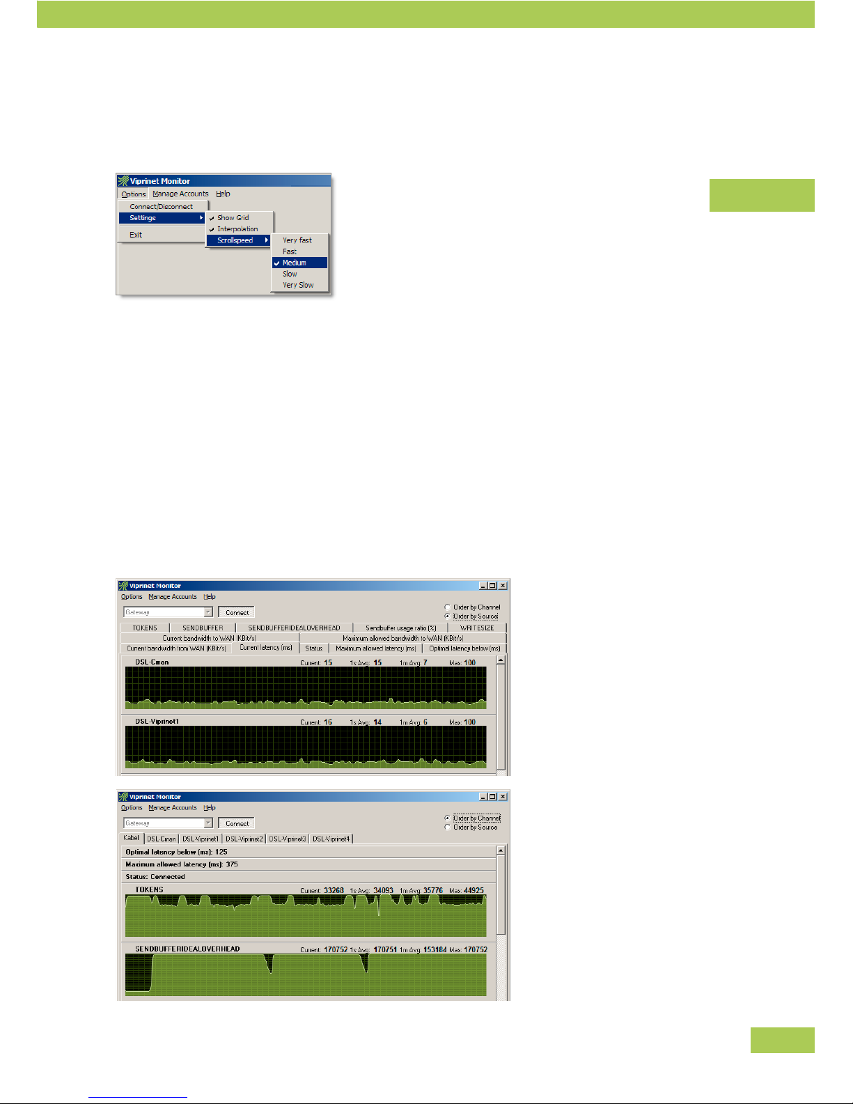
Using the dedicated monitoring tool application (compatible with Windows 2000/XP/Vista/7) you may
remotely monitor bandwidth utilization and other performance information of the router's VPN Tunnels and
WAN modules in real time in a graphical fashion. This tool also is very suitable to do diagnostics on under
performing WAN lines, e.g. to check if a line is overloaded, causing abnormal latency.
Start the Monitoring System program •
Programs » Viprinet » Monitor
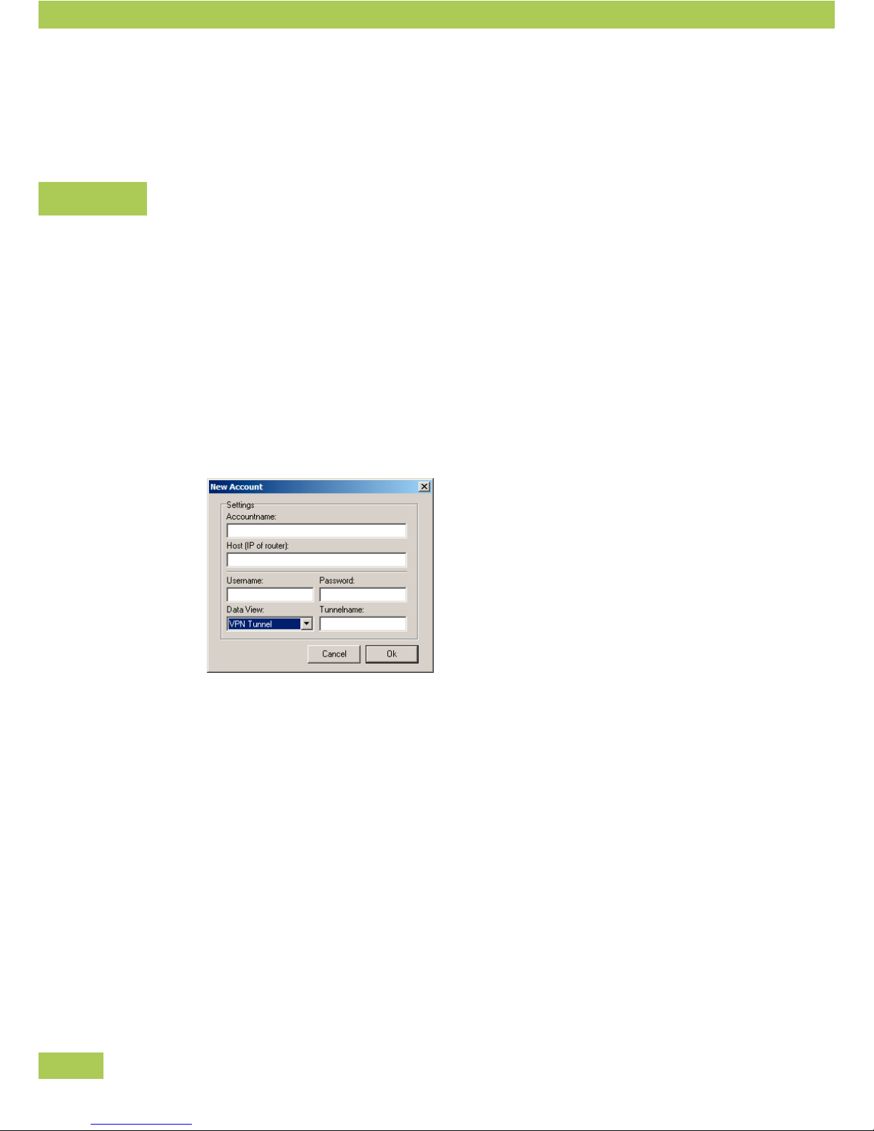
Create account
You can create a single account for each router.
Select • Account » New
The account name is an internal identification of the router. •
As host name, enter host name or IP of the router to be accessed (IP of the LAN Interface). •
Username and password correspond to a user account of the Web Interface of the respective router. •
You may chose between the root account or a user account with reading rights for the queried VPN
Tun nel.
Enter the name of the VPN Tunnel to be queried. The name must correspond to the name at “VPN •
Tunnels” in the Web Interface.
Other
Page 49
49
Settings
You can chose how data streams are displayed.
Select Options » Settings » ... to activate or deactivate the options.
Display Account
Select • Account » Account name, to display the account.
Select •
Order by Channel or
Order by Source
Select the desired tab.•
Other
Page 50

50
Integration of VPN Clients/Road Warriors
Every Viprinet Router may, in addition to site-to-site VPN Tunnels, provide service to an unlimited number
of connections from VPN Clients.
A VPN Client is a single computer which is located outside all networks connected per VPN. This can •
be a field representative or a home office.
These single workstations can be connected to the VPN network using VPN Client connections. The •
VPN Client integrates itself as a virtual network card into the operating system and then uses –
comparable to the Multichannel VPN Router – up to two available broadband connections (like UMTS
and WLAN) dynamically.
The VPN Clients dial into the Viprinet Router at the data center (VPN Hub). •
A separate software with separate licence is needed. •
See separate manual for instructions on installation and usage.•
Other
Page 51

51
Service
Trouble shooting
Password forgotten or router no longer accesible
Should you have forgotten your root password, or should the router, due to misconfiguration, be unac-
cesible through the LAN-interface, the router can be resetted to delivery status with the reset button.
Before taking this action, you should verify that the router is wired correctly.
Resetting the Viprinet Router
To reset the router into initial state, hold the reset button at the front end for at least 5 seconds (e.g. with
a pencil). The router will now reset to default settings and restart. After about two minutes, the router
should be found in the setup program. It can be configured anew.
Attention: By resetting the router, all congurations will be past recovery. The LAN-interface congura-
tion will be deleted as well, the router will then be accessible through the setup program only. Details on
reconfiguration can be found in the chapter Basic Configuration Using the Setup Program.
Service
Page 52

52
Service providers
Internet
Find current documentation and FAQ at: http://www.viprinet.com
Supplier
Turn to your supplier for help, e.g. with the configuration.
Address, Hotline:
Service
Page 53

53
Service
Page 54

54
Appendix
CIDR notation
In CIDR notation, a suffix is added, e.g. /24 to show how many bits of the address identify the network
(and are therefore not available). In the CIDR notation all digits which are 0 can be left out (seen from the
right) – 10/8 is the abbreviated form for 10.0.0.0/8 (resp. “net starting at 10.0.0.0 with 8 bits identifying the
network”).
192.168.1/24 means: •
24 Bit bits identify network, ranges from 192.168.1.0 to 192.168.1.255 are available.
192.168.1.0/25 means: •
25 Bit bits identify network, ranges from 192.168.1.0 to 192.168.1.127 are available.
192.168.1.128/25 means: •
25 Bit bits identify network, ranges from 192.168.1.128 to 192.168.1.255 are available.
Example
CIDR Address Netmask Explanation
192.168.2.7/24 192.16 8. 2.7 255.255.255.0 The notation 192.168.2.7/24 stands for
the address 192.168.2.7 with the netmask
255.255.255.0: this is 11111111.11111111.111111
11.00000000 in binary – there are 24 1-bits as
indicated in the suffix. Using an AND-operation
the net address 192.168.2.0 can be determined
from this address. Therefore, the IP address
is located in a net ranging from 192.168.2.0 to
192.168.2.255.
10.43.8.67/28 10.43.8.67 255.255.255.240 10.43.8.67/28 stands for the address 10.43.8.67
with the netmask 255.255.255.240. In binary: 1
1111111.11111111.11111111.11110000 – there are
28 10bits as indicated in the suffix. The IP net
where the host 10.43.8.67 is located ranges
from 10.43.8.64 to 10.43.8.79 and is abbreviated
by 10.43.8.64/28
The broadcast address is 10.43.8.79, network
address 10.43.8.64 and the subnet can address
14 hosts.
Appendix
Page 55

55
CIDR
Number of
addresses
Netmask Netmask in binary
/8 16777216 255.0.0.0 11111111.00000000.00000000.00000000
/9 128x65536 255.128.0.0 11111111.10000000.00000000.00000000
/10 64x65536 255.192.0.0 11111111.11000000.00000000.00000000
/11 32x65536 255.224.0.0 11111111.11100000.00000000.00000000
/12 16x655 36 255.240.0.0 11111111.11110000.00000000.00000000
/13 8x65536 255.248.0.0
11111111.11111000.00000000.00000000
/14 4x65536 255.252.0.0 11111111.11111100.00000000.00000000
/15 2x65536 255.254.0.0 11111111.11111110.00000000.00000000
/16 65536 255.255.0.0 11111111.11111111.00000000.00000000
/17 128x256 255.255.128.0 11111111.11111111.10000000.00000000
/18 64x256 255.255.192.0 11111111.11111111.11000000.00000000
/19 32x256 255.255.224.0 11111111.11111111.11100000.00000000
/20 16x256 255.255.240.0 11111111.11111111.11110000.00000000
/21 8x256 255.255.248.0 11111111.11111111.11111000.00000000
/22 4x256 255.255.252.0 11111111.11111111.11111100.00000000
/23 2x256 255.255.254.0 11111111.11111111.11111110.00000000
/24 1x256 255.255.255.0 11111111.11111111.11111111.00000000
/25 128x1 255.255.255.128 11111111.11111111.11111111.10000000
/26 64x1 255.255.255.192 11111111.11111111.11111111.11000000
/27 32x1 255.255.255.224 11111111.11111111.11111111.11100000
/28 16x1 255.255.255.240 11111111.11111111.11111111.11110000
/29 8x1 255.255.255.248 11111111.11111111.11111111.11111000
/30 4x1 255.255.255.252 11111111.11111111.11111111.11111100
/31 2x1 255.255.255.254 11111111.11111111.11111111.11111110
/32 1x1 255.255.255.255 11111111.11111111.11111111.11111111
Appendix
Page 56

56
Netmask
A netmask is a bit mask that divides an IP address into a network and a device part. It is used in IP net-
works to make routing decisions. The netmask is also called network mask and subnet mask.
Structure and notation of a netmask
A netmask is as long as the IP address it is used on (that is 32 bit for IP version 4). All bits of the network
part are set to 1 and the bits for the device are set to 0.
The notation of a netmask is mostly not in binary but (as also usual for IP addresses) in decimal. Therefore,
an Ipv4 address for a 27 bit network part is 255.255.255.224 or in CIDR notation: /27.
decimal 255 255 255 224
dual 11111111 11111111 11111111 11100000
The number of 1-bits is 27 that is /27 in CIDR notation.
The usable address range of a net is defined by its netmask. With a /27 net, the first 27 digits of an IP ad-
dress are the net part and identical for all hosts in the net.
Determining of network and device part using the netmask
The two parts of the Ipv4 address 130.94.122.195/27 can be determined using AND-operations. The
netmask for /27 is 255.255.255.224 (see CIDR notation).
decimal binary calculation
IP address
Netmask
Network part
13 0.0 94 .122 .195
255.255.255.224
130.094.122.192
10000010 01011110 01111010 11000011
11111111 11111111 11111111 11100000
10000010 01011110 01111010 11000000
IP address
AND netmask
= net work part
IP address
Netmask
Device par t
13 0.0 94 .122 .195
255.255.255.224
3
10000010 01011110 01111010 11000011
11111111 11111111 11111111 11100000
00000000 00000000 00000000 00000011
IP address
AND (NOT netmask)
= device par t
Appendix
Page 57

57
Division of addresses
You can divide address spaces to create separate ranges – subnets – for single LANs.
Division of private addresses decimal
If you are using the private address space, it is easy to divide the addresses using the decimal
representation.
Range
Examples for
branch offices
Annotations
192.168/16 192.16 8.1/ 24
192.168.2/24
192.168.3/24
etc.
Up to 256 branch offices with up to 254 hosts can be
provided.
The netmask is 255.255.255.0
10/8 10.0.1/24
10.0.2/24
10.0.3/24
etc.
There may be up to 65536 branch offices with up to 254
hosts.
The netmask is 255.255.255.0
10.1/16
10.2/16
10.3/16
etc.
Up to 256 branch offices with up to 65534 hosts can be
provided.
The netmask is 255.255.0.0
Division of private addresses binary
If the address space is not sufficient because you have more branch offices or need more hosts per branch
office, you may split up the address space at any digit of the binary representation. When splitting up
the net 192.168/16 in subnets with the size /23 (510 hosts per subnet), the first subnet would start at
192.168.0/23, the second at 192.168.2/23, the third at 192.168.4/23, etc.
CIDR Number of branch offices Number of hosts
/20 2
4
= 16 212 = 4.096
/21 2
5
= 32 211 = 2.048
/22 2
6
= 64 210 = 1.024
/23 2
7
= 128 29 = 512
/24 2
8
= 256 28 = 256
Appendix
Page 58

58
Division of public addresses
When using an address space in the public range, you will have to split as exact as possible to spare the
limited public IP address range, that is in binary: e.g. the range 192.0.2.0/24 was assigned to you. That
means that the first 24 bit are needed to identify the net and you can freely assign 8. In binary representa-
tion, you can reserve bits for the net (1) and bits for the hosts (0). You have the following possibilities at
your disposal:
CIDR Number of branch offices Number of hosts
/25 2
1
= 2 27 = 128
/26 2
2
= 4 26 = 64
/27 2
3
= 8 25 = 32
/28 2
4
= 16 24 = 16
/29 2
5
= 32 23 = 8
Appendix
Page 59

59
NAT-Network Address Translation
The Viprinet Router supports NAT. Using NAT, a request coming from the private IP address of a PC inside
the VPN will get its source IP replaced with a public one before packets get forwarded to the Internet.
Replies coming back from the Internet for this connection are then translated back by replacing the destina-
tion IP address of the reply packets back to the private one from the PC. Here is an example:
A request from branch ofce 1 is to be sent to Google •
The VPN Node router in the LAN sends the request to the VPN Hub via VPN Tunnel •
The VPN Hub router in the data center replaces the private sender IP by its public NAT-IP and •
forwards to the Internet
The VPN Hub stores this assignment in an internal table •
The request reaches Google •
Google answers to the public IP •
The VPN Hub replaces the target address of the answer with the saved private address and forwards •
it to the appropriate VPN Node.
The VPN Node sends the answer to the querying PC in the LAN.•
NAT configuration in the Viprinet Router
When configuring a network, you should always care to chose a router at the periphery to configure for
NAT. Normally, this would be the VPN Hub because it is, due to its connection to the Internet, the network
border.
Theoretically, it is also possible to configure a Viprinet Router at a branch office for NAT. This however is
not recommended, because it makes it impossible for the VPN Hub to distinguish between different hosts
on the VPN.
Appendix
Page 60
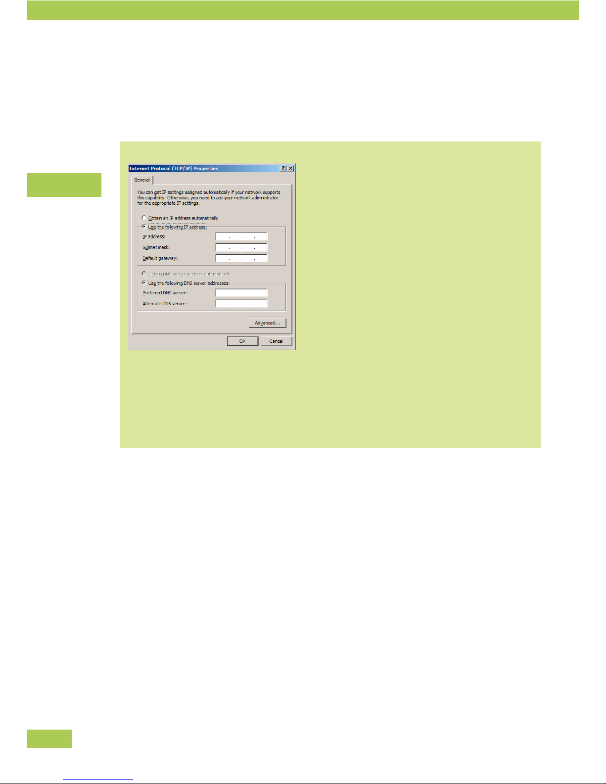
60
IPs for computers in the LAN
Each computer within the LAN has to get its own IP address. In addition, the netmask, gateway as well as
the name server need to be configured. For every computer choose, e.g.
Obtain an IP address automatically:
This setting is sensible in most cases. If activated,
all other settings are obtained automatically. The
DHCP server has to be activated either in the
Viprinet Router or on another server that assigns IP
addresses from the correct network range.
IP address:
Each computer needs its own IP address.
Subnet mask:
The subnet mask is determined by network and
device part.
Default gateway:
Enter the IP address of the Viprinet Router.
Preferred DNS server:
Enter the IP address of the Viprinet Router.
Appendix
Page 61

61
Page 62

 Loading...