

Viprinet 2610, 1610, 300 User Manual
Manual
Viprinet Multichannel VPN Router
™
Model 1610/2610

2
Imprint
As of 4/2010
Subject to technical changes.
Producer:
Viprinet GmbH
Mainzer Str. 43
55411 Bingen am Rhein
Germany
Phone: +49 (0)6721 4 90 30-0
Fax: +49 (0)6721 4 90 30-109
E-mail: info@viprinet.com
Web: www.viprinet.com
© 2007-2010 Viprinet GmbH
Pictures by Frauke Boensch
Reprinting or copying even in extracts only with written permission of Viprinet GmbH.

3
Table of contents
General information 4
Product at a glance 4
Device description 9
Technical data 10
Unpacking 10
Delivery content 11
Installation 12
Device setup 12
Installation of line modules 13
Installing the software 15
Wiring the network 16
Configuration 18
Network knowledge is necessary 18
Overview 18
Choosing topology 20
Net segmentation 22
Basic configuration using the setup program 26
Configuration using the web interface 34
Tunnel Channel Autotuning 39
Qos System and Bonding Options 43
SNMP 46
Additional information 48
Monitoring system 48
Integration of VPN Clients / Road Warriors 50
Service 51
Trouble shooting 51
Service providers 52
Appendix 54
Network basics 54
NAT-Network Address Translation 59
4
General information
Product at a glance
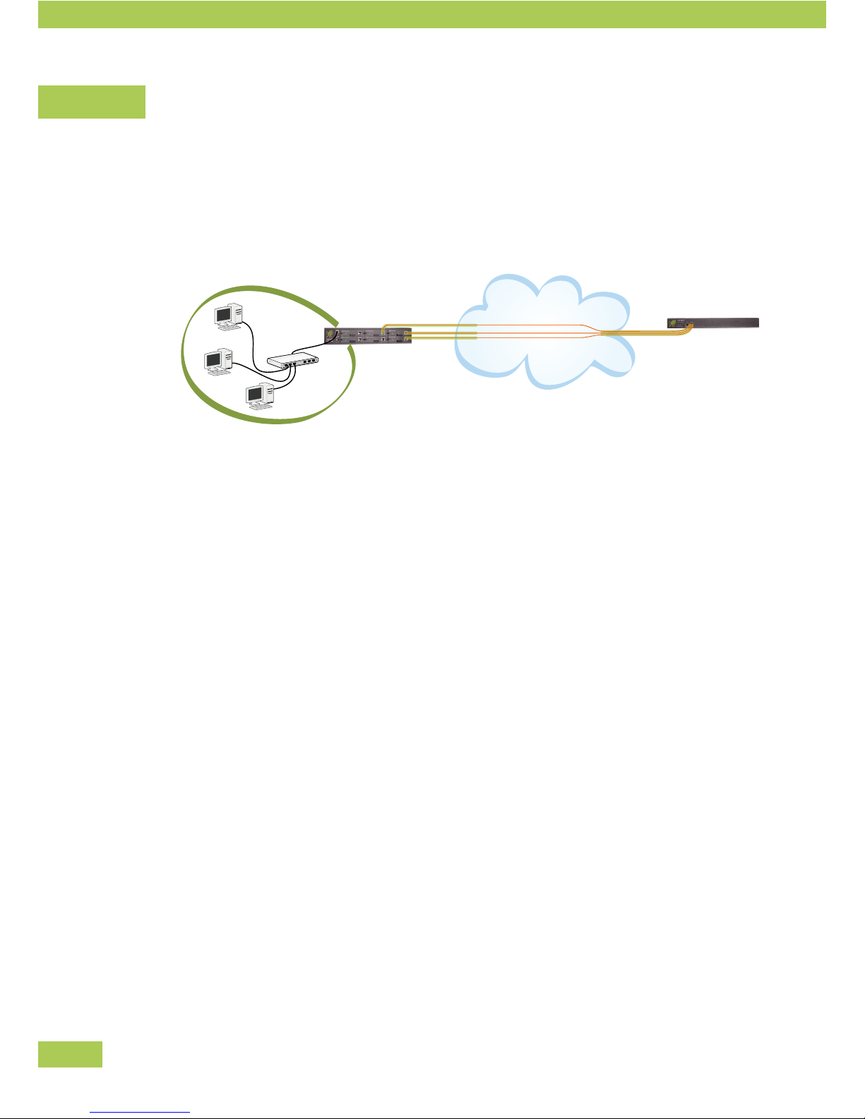
The Multichannel VPN Router connects a local network via up to six broadband channels with a Multichan-
nel VPN Hub, which is acting as a VPN concentrator. At least two Viprinet Routers are needed for this
connection:
Internet
• Left: local network with a Viprinet Multichannel VPN Router (VPN Node).
• Right: data center with Viprinet Multichannel VPN Hub (VPN Hub).
For the most common types of connections the following modems are available as modules which are
inserted into the router case.
• ADSL/ADSL2+ Annex A *
• ADSL/ADSL2+ Annex B *
• Euro-ISDN
• UMTS/HSPA/EDGE
• Fast Ethernet
External modems (e.g. WLAN, SDSL, SHDSL) may be connected using the Fast Ethernet module. All
modems that either allow PPPoE pass-through or are able to assign an IP address statically via DHCP are
supported.
Technology
The Multichannel VPN Router acts as a Layer 3 router connecting local networks at different locations on
the IP level. IP data steams are picked up by the LAN interface and are distributed to all available channels/
modem modules. As parts of data streams are sent through multiple channels, a Viprinet peer (called “VPN
Hub”) is always needed to reassemble the streams afterwards.
Preface

5
Safety/data encryption
For each physical Internet connection, a separately encrypted VPN Tunnel (SSL protocol using 256 Bit
AES encryption) is set up between the VPN Node and the VPN Hub. These tunnels are used in a bundled
fashion, and all IP traffic is then passed through it.
Cooling
The Viprinet Router is set up for continuous operation and is cooled using regulated redundant case fans.
It is critical that the ventilation slots are never covered and the maximum specified ambient temperature is
not exceeded.
* Annex A / B
Annex A ADSL frequency range for analogue telephone connections
Annex B ADSL frequency range for ISDN telephone connections
Basics of VPN Tunnels / Terminology
VPN Hubs, VPN Nodes and VPN clients
The Multichannel VPN Router is usually used to connect one or multiple branch offices to a central location.
Generally, together all locations therefore form a star topology.
VPN Node
A router not accepting VPN connections from other routers but connecting to a cen-
tral VPN Hub is called VPN Node. VPN Nodes typically use multiple physical Internet
connections using WAN modules.
VPN Hub
A router accepting connections from VPN Nodes at a central location (data center,
company headquarters, ISP) is called VPN Hub.
VPN Clients
Single computers not located inside a network equipped with a VPN Node (e.g. Field
representatives with notebooks, home offices) may use a Software-based solution
to become part of the VPN network. These are called VPN Clients. Using the VPN
Client software, a VPN Tunnel to a VPN Hub is created.
Preface

6
The LAN port
The router is integrated into the LAN using an Ethernet switch connected to the router's LAN port.
Using the LAN port, the web conguration system “AdminDesk” can be •
accessed from the LAN using a web browser.
Only via the LAN port, the router can be accessed by the setup software to perform the initial •
configuration.
Using the LAN port, the appropriately congured router can offer integrated services like a domain •
name server and a DHCP server to assign IP addresses to computers within the LAN.
Within the web conguration system “AdminDesk”, conguration of the LAN port is performed using the
“LAN settings” menu.
The WAN Interfaces / Module slots
The modem cards inserted into the router's module slots are called “WAN Interfaces”:
Each module used must be configured according to its type:
A DSL modem, for example, requires the PPP account data from the DSL provider.•
For dialup lines (or UMTS links) that are billed by time it might be sensible to use a configuration that •
will only dial in if a tunnel within the router is actually trying to connect to the VPN Hub.
VPN Tunnels
To connect a VPN Node with a VPN Hub, the VPN Node has to establish a TCP/IP tunnel with a VPN Hub.
The data from the VPN Node's LAN is sent via this encrypted tunnel to the VPN Hub which forwards it to
another VPN Node (that is, another location) or the Internet.
Such a logical connection between VPN Node and VPN Hub is called a “VPN Tunnel”. Within AdminDesk
this can be configured in the “VPN Tunnels” menu.
Tunnel Channels
To create such a logical VPN Tunnels, TCP/IP connections with the VPN Hub have to be established through
the ISPs used by each WAN Interface.
Thanks to its innovative channel bundling technology, the Multichannel VPN Router is able to use •
several physical lines provided by different ISPs to create such a VPN Tunnel.
Each physical connection created by a VPN Tunnel using a WAN Interface is called “Tunnel Channel”. •
A VPN Tunnel contains at least one such Tunnel Channel to make a connection possible.
Preface

7
A Tunnel Channel contains the information which of the existing WAN Interfaces is used to create •
the physical connection.
With a VPN Node connected to just one VPN Hub (usual case) a Tunnel Channel per existing WAN Interface
will be created. On the VPN Hub things look different: All Tunnel Channels come in through one single
WAN/VPN-Port connected to the datacenter's backbone..
A VPN Node uses a Tunnel consisting of multiple Tunnel Channels, which each refer to a single WAN •
Interface, to link to the VPN Hub.
A VPN Hub connected with several branch offices (VPN Nodes) uses one Tunnel per VPN Hub, with •
each Tunnel consisting of multiple Tunnel Channels.
Traffic Classes and Rules / Quality of Service
The Multichannel VPN Router distinguishes itself by an innovative bundling procedure. This makes it pos-
sible to internally combine all Tunnel Channels used by a VPN Tunnel for certain services. The bandwidth
of all used Tunnel Channels (that is, of all physical lines of the WAN Interface) may be summed up for
individual up-/ downloads.
This bundling procedure is only sensible for certain kinds of traffic – that is, if the complete band-•
width of all Tunnel Channels should be used with a small number of connections.
This is, for example, not necessary for IP telephones (VoIP) – latency, that is the time the data needs •
to pass between VPN Node and VPN Hub, is far more important.
The Multichannel VPN Router allows you to very precisely configure how the router should deal with
certain types of data traffic. The setting how a defined group of data traffic is treated is called “QoS Traffic
Class”.
This makes it possible to set up a class for data traffic like IP telephony, always assigning it to the •
line with the smallest latency (possibly moving it to a different line as soon as that becomes the one
with the lowest latency).
For traffic needing the highest possible bandwidth, a class may be set up where all available Tunnel •
Channels are used for the data transfer.
By using the QoS classes it is also possible to guarantee or restrict the bandwidth for certain classes of
data transfers. The router makes sure that a Traffic Class with a guaranteed bandwidth will be preferred –
even if the system is running on full capacity – cutting down bandwidths of other classes to always keep
the guaranteed bandwidth available. Other classes on the other hand might be restricted to a maximum
amount of bandwidth – this way certain unimportant services like file sharing may be slowed down. QoS
Traffic Classes define how individual classes of data transfer are dealt with.
Preface

8
The second component of the Quality of Service system are the “QoS Traffic sorting rules”. These are rules
to sort data streams by different criteria into the QoS Traffic Classes mentioned above.
Several criteria may be used to do so:
Data may be sorted by the TCP port used. A QoS Traffic sorting rule might identify all connections •
from and to Port 80 as HTTP connections. The rule would be called “HTTP”. As part of this rule, a
target class would be set – for example: the QoS Traffic Class “bundling”.
A rule might also use source and target ranges of your IP network. This way, a department may be •
identified by its IP address and sorted into a certain QoS Traffic Class that guarantees a minimum
bandwidth.
Preface
9
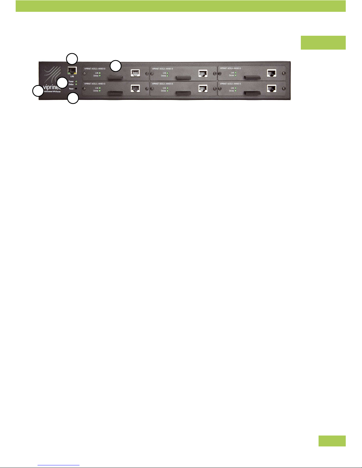
Device Description
(1) IEC C14 socket for electric power (backside)
(2) LAN-socket
Link to local network
(3) Viprinet router status LEDs
Power: lit when power is supplied
Online:
lit when connection to a VPN Hub is established •
through at least one line
flashing while system is establishing connection to a VPN Hub•
(4) Reset button
The reset button can be reached with a pointed object (e.g. pencil). By pushing it briefly, the router
will restart. By continuously pushing the button for 5 seconds, the router will be reset to factory
settings. Caution: all settings will be lost! Further information for this can be found in the “service”-
chapter.
(5) Six slots for hot plug modules
Each with LEDs for status indication:
Link:
lit when cable is connected correctly•
ashing while module is trying to synchronize with ADSL-DSLAM (ADSL-module only)•
flickering when line is active•
Online:
lit when a VPN Tunnel is established with this module•
blinking when module is used to establish a VPN Tunnel•
Screws
All screws you may open are Phillip screws (e.g. screws for fixing angle-irons and module faceplates). All
other screws are Torx screws and must not be opened.
Preface
1
4
3
2
5
10
Technical Data
Model 1610 2610
Enclosure 19" 1,5 HE 19" 1,5 HE
Measures WxHxD 435 x 66 x 320 mm 435 x 66 x 320 mm
Weight 5,1 kg 5,1 kg
Power supply input 100-240 VAC, 50-60 Hz 100-240 VAC, 50-60 Hz
Power connector IEC C14 socket IEC C14 socket
Number of fans / controlled / monitored
2 / ü / - 2 / ü / -
LAN interface GBit Ethernet GBit Ethernet
WAN module slots 6 6
Maximum input wattage 70 Watt 75 Watt
Typical wattage 40 Watt 45 Watt
SNMP Status / Accounting
ü / « ü / ü
Bonding capacity MBit /s 125 200
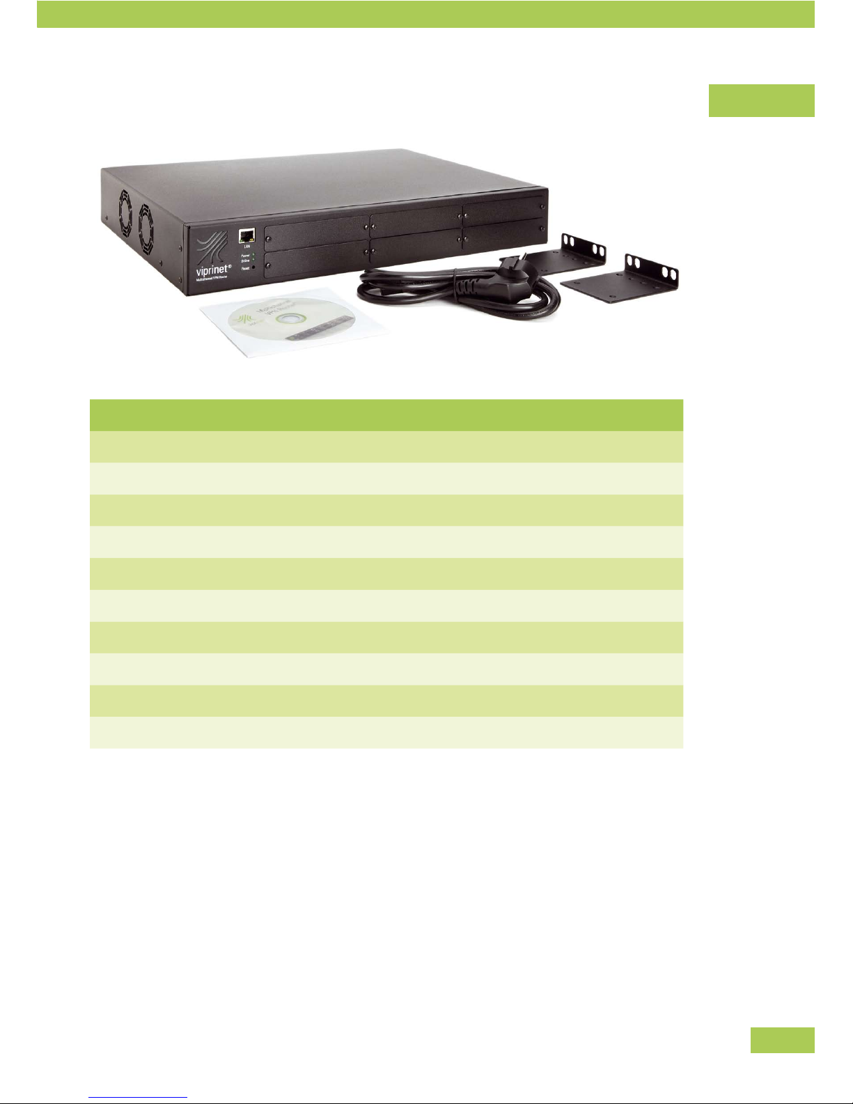
Unpacking
The Viprinet Router and the modules will be sent singly or pre-configured depending on the supplier.
Unpack all elements and check if complete.
Preface
11
Delivery content
Number Type
1 Multichannel VPN Router (model number see identification plate on the backside)
1 Power Cable
1 Manual
1 CD with software
2 Angle-irons for inserting router into 19” rack
* ADSL/ADSL2+ module Annex A
* ADSL/ADSL2+ module Annex B
* Euro-ISDN module
* Fast Ethernet module
* UMTS/GPRS/EDGE module
* Number of modules due to your order. See delivery note.
Preface
12
Installation
Device setup
The Viprinet Router is a desktop device and can be put up at any location which offers the following
conditions:
Working temperature 10-35°C•
No direct sunlight (danger of overheating)•
Detached position•
Attention:
The ventilation shafts must not be covered. There must be at least a space of 5cm on both sides of the
device to assure proper ventilation to prevent overheating.
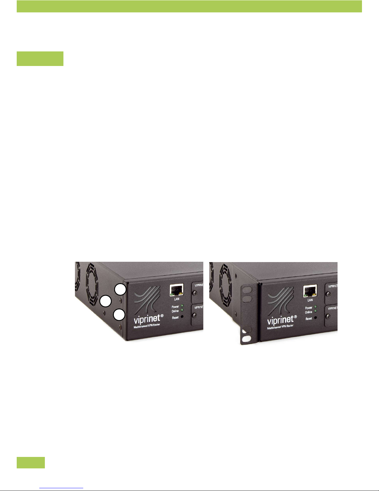
Installation into 19" rack
If necessary, the Viprinet Router can be mounted into a 19” rack. Angle-irons are included in the delivery.
Mounting of Angle-irons
• Unscrew the three Phillips screws left and right (1)-(3).
• Attach the angle-irons to both sides with these screws.
• The Viprinet Router can now be inserted into a 19” rack.
Installation
3
2
1

13
Installation of line modules
Up to 6 line modules can be inserted into the Viprinet Router. Modules can be plugged into any of the slots.
They may be installed or taken out even when the router is running (hot-plug).
If modules are reassembled, the configuration has to be changed (see below).
Unscrew both screws.•
Take off the cover (resp. pull out the module).•
Insert the chosen module into the slot. •
Keep in mind to put the board straight into the rails.
Put the screws back in.•
The module has to be configured. •
First configuration: use the setup program or the Web Interface.
For any upgrade: use the Web Interface.
Numbering of modules
All module slots are numbered internally. The configuration is saved for each slot.
Installation
3
6
2
5
1
4

14
Replacement of modules
You can exchange a module in slot 1 with another one of the same type.•
The configuration is maintained. •
This way, you can, for example, exchange one ADSL module with another ADSL module. Slot and
configuration stay the same.
If extracting a configured module and replacing it with a different type, the previous configuration of •
the slot is lost.
ADSL Annex A and B are seen as the same type of module.•
Installation

15
Installing the software
The following software is delivered with the Viprinet Router and should be installed on a workstation/
desktop.
Setup program
Setup program for configuring the Viprinet router.
File name: setup.exe
Monitoring system
Monitoring system displaying of the data streams.
Setup file name: monitor.exe
Installation of the setup program
There is no need to install the setup program. The exe-file can be executed immediately
Copy the exe-file to your desktop or execute directly from CD.•
Installation of Monitoring system
You can install the Monitoring system on your desktop.
Insert CD.•
Start monitor.exe from CD.•
Follow instructions on screen.•
Installation
16
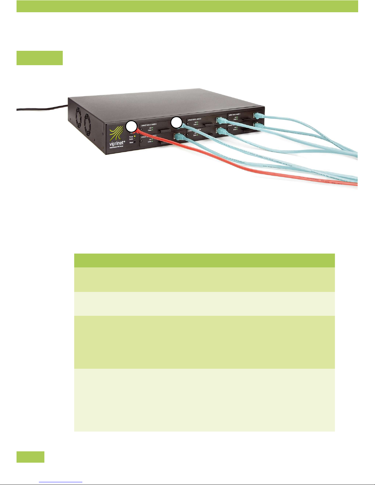
Wiring the network
Connect the Viprinet Router with the network and the lines as follows:
Connect the LAN port (1) with the local network,•
e.g. a work-group switch•
e.g. a firewall system •
Connect the module with the lines. Notice the following tips.•
Module Type
ADSL /ADSL2+ module Annex A
Network cable (if necessary shielded) (CAT5)
Connect with splitter, “DSL” socket
ADSL /ADSL2+ module Annex B
Network cable (if necessary shielded) (CAT5)
Connect with splitter, “DSL” socket
Euro-ISDN module
ISDN cable with RJ-14 plug or network cable (if necessary
shielded) (CAT5)
Connect with NTBA
(Alternatively, you can also connect to ISDN bus of a tele-
phone system installation, e.g. “s0 intern”)
Fast Ethernet module
Network cable (if necessary shielded) (CAT5)
Connect with Ethernet socket of a router or modem, e.g.:
cable modem•
SDSL modem•
radio link •
leased line router•
Installation
2
1

17
Module Type
UMTS/GPRS/EDGE-Module
Mount the UMTS antenna shipped with the module to the
SMA socket. Alternatively an external UMTS antenna
equipped with an SMA plug may be connected.
Installation

18
Configuration
Network knowledge is necessary
For correct Viprinet Router configuration sufficient network knowledge is necessary. You will find an over-
view of important terms in the appendix. See: Basic Network Technology.
Overview
Below you will find a compact overview about the steps you need to take in order to use the router inside
your network:
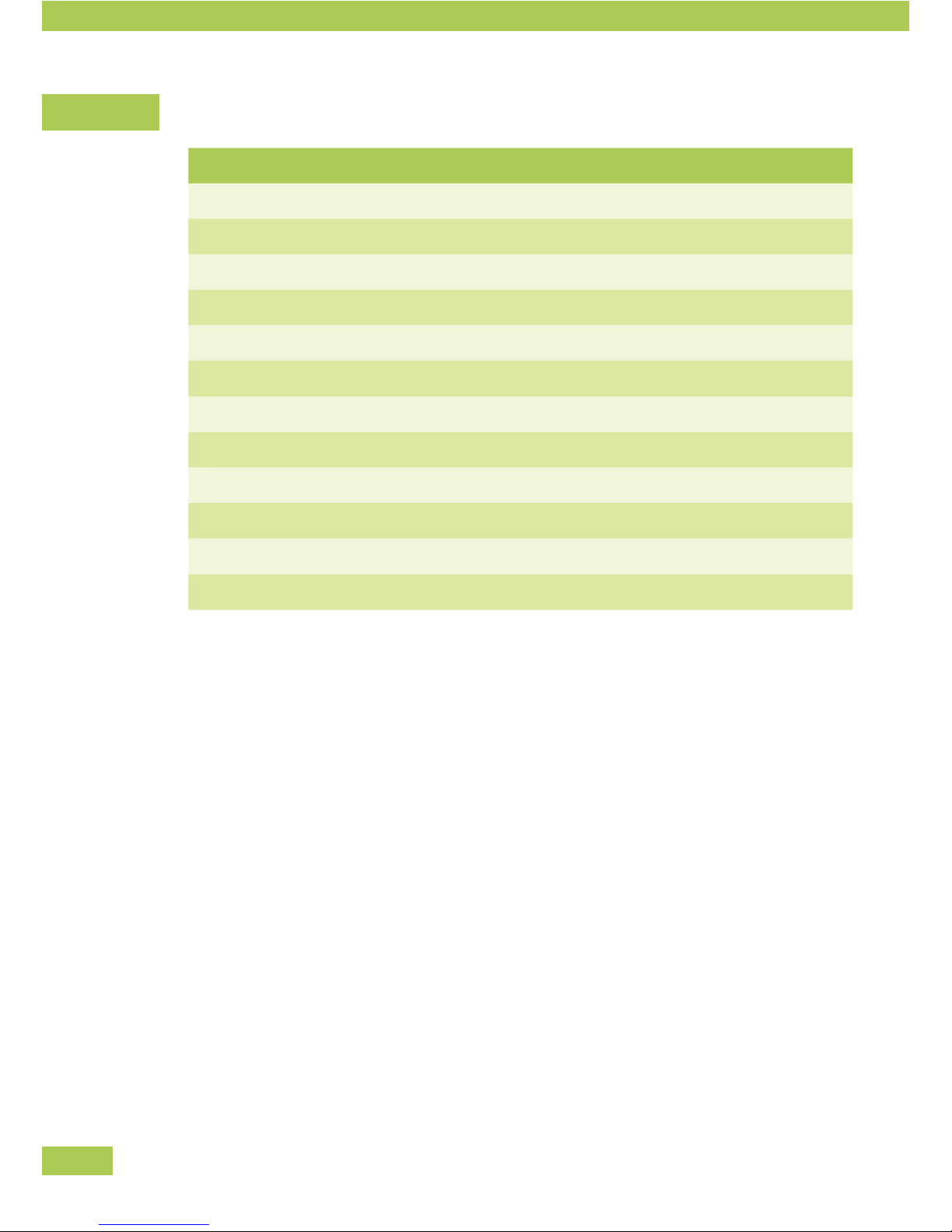
Step Action
Define topology
You should first decide on a network topology. As a rule, it should
be established in a star topology – one or more VPN Nodes con-
nected to one central VPN Hub forwarding to the Internet and
routing between the VPN Nodes.
Net segmentation
Since the Viprinet Router is active as a Layer 3 router, the
networks which are to be connected have to have their own IP sub-
nets. So you will have to segment your entire IP network consisting
of private and public IP ranges. The Viprinet Router working as a
VPN Hub will route between those subnets.
Get public IPs
You need public IPs for the following devices:
VPN Hub •
1. an IP for the Uplink/LAN port (routing towards the Internet
is done from here; connections from the VPN using private IP
addresses are converted to this IP address using NAT.)
2. an IP address for the WAN/VPN interface (may use same
IP subnet as the LAN port)
for all VPN Nodes •
1. An IP address for each module (typically dynamic IP
addresses, automatically assigned by service provider, are
used here though)
Configuration

19
Basic configuration
(Setup program)
At first use, you will have to install a basic configuration on each
Viprinet Router using the setup program.
The following values are determined:
router name•
local IP and netmask•
VPN Node/ VPN Hub•
LAN Interface settings•
module configuration•
VPN connection configuration•
router password •
If needed, sophisticated
configuration
(Web Interface)
If required, you can set up further congurations by using the Web
Interface. Here, the values of the basic configuration can be changed
and further parameters can be added like:
all LAN and module settings•
Tunnel and Channel settings•
bandwidth management (priority settings for certain data •
streams)
user rights •
Configuration
 Loading...