

Page 1
Page 2

CONGRATULATIONS on your purchase of a Viper product
and welcome to the V.I.P. family. We appreciate your
business and will do everything in our power to keep you happy
with your purchase for many years to come.
As part of the V.I.P. family, you are entitled to the best
protection by one of the most comprehensive warranties in
the industry.
Thank-you for purchasing Viper products!
Tom Vander Bie, CEO
TABLE OF CONTENTS
Safety Precautions 3
Machine Operation 4
Machine Maintenance & Storage 4
Parts List 5---8
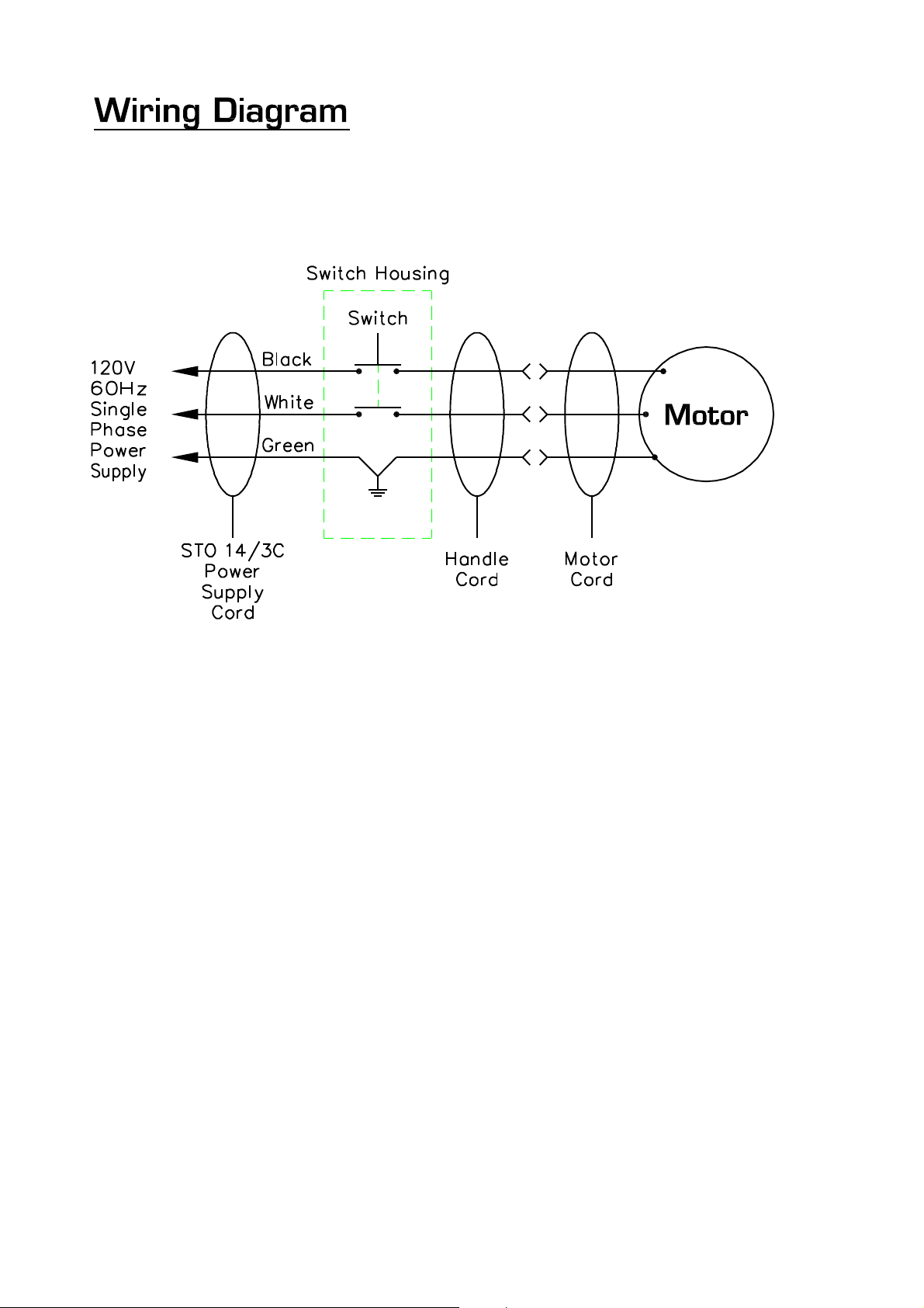
Wiring Diagram 9
T
2
Page 3
SAFETY PRECAUTIONS
GROUNDING INSTRUCTIONS
General –This floor – finishing machine shall be
grounded while in use to protect the operator
from electric shock. The machine is provided
with a three –conductor cord and a three contact
grounding type attachment plug to fit the proper
grounding type receptacle. The green [or green
and yellow] conductor in the cord is the
grounding wire. Never connect this wire to other
than the grounding pin of the attachment plug.
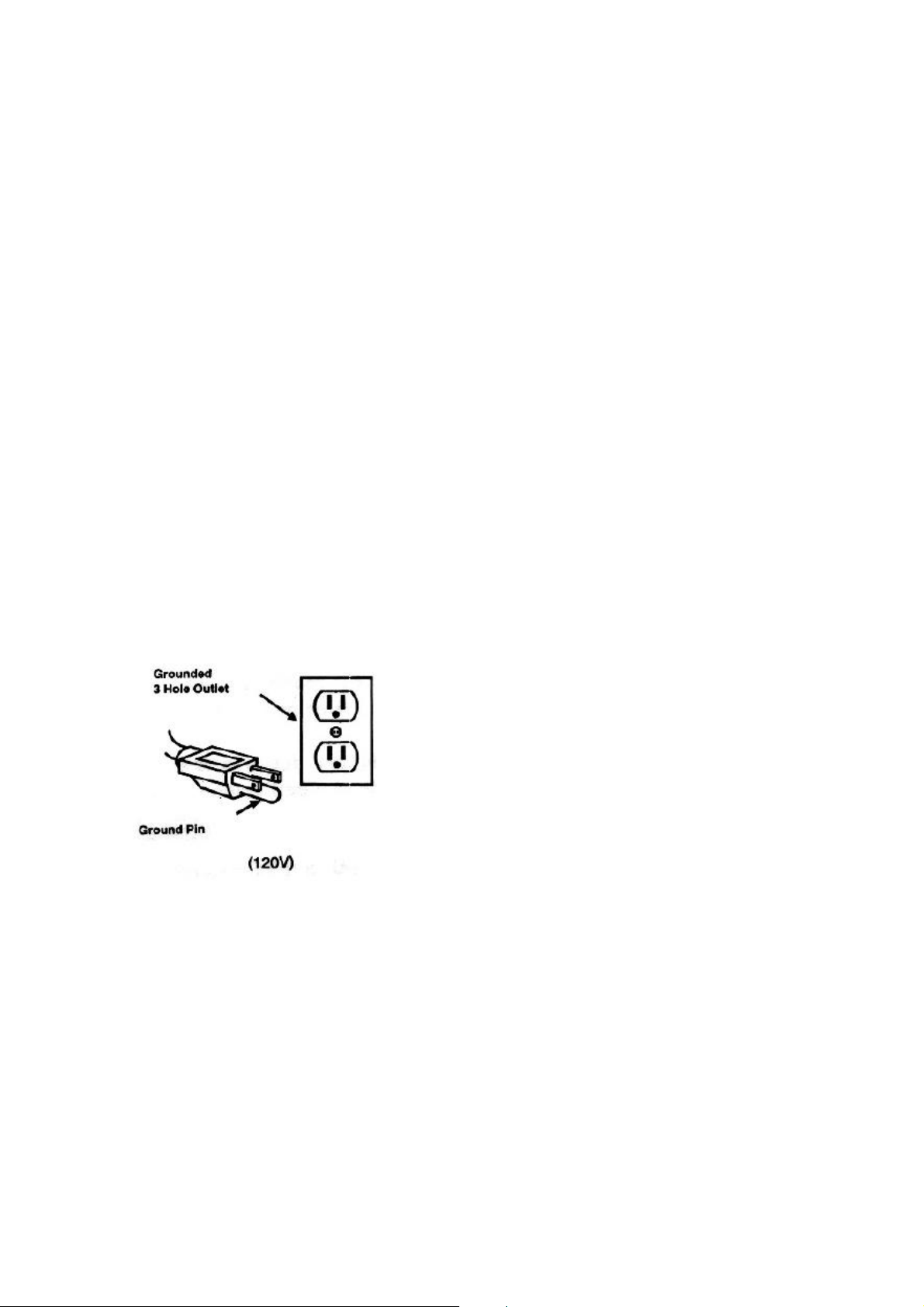
This machine is for use on a nominal 120-Volt
circuit and has a grounding plug that resembles
the plug illustrated in figure below. Make sure
that the machine is connected to an outlet
having the same configuration as the plug. No
adapter should be used with this machine.
- Unless trained and authorized.
- Unless you have read and understand
operators manual.
- In flammable or explosive areas.
- With a damaged cord or plug.
- If not in proper operating condition.
- In outdoor areas.
- In standing water.
- With the use of extension cords.
2] Before operating machine:
- Make sure all safety devices are in place
and operate properly.
3] When using machine:
- Do not run machine over cord.
- Do not pull machine by cord or plug.
- Do not pull cord around sharp edges of
corners.
- Do not unplug by pulling on the cord.
- Do not stretch cord.
- Do not handle plug with wet hands.
- Keep cord away from heated surfaces.
- Report machine damage of faulty
operation immediately.
This machine is intended for Commercial use. It
is constructed for use in an indoor environment
and is not intended for any other use. Use only
recommended accessories.
All operators shall read, understand and
exercise the following safety precautions:
1] Do not operate machine:
4] Before leaving or servicing machine:
- Turn off machine.
- Unplug cord from outlet.
5] When servicing machine:
- Unplug cord from outlet.
- Use manufacturer supplied or approved
replacements parts.
-
3
Page 4

Operation of Floor Machines
* READ OPERATORS MANUAL
THOROUGHLY PRIOR TO OPERATING OR
SERVICING THIS MACHINE.
GENERAL USE
1.
2.
* Be sure the machine is not plugged into
an outlet
3.
4.
5.
Never use an extension cord in
conjunction with the standard power cord.
6.
7.
Never change the speed while operating
the machine. Be sure the power is turned
off prior to changing the speed.
8.
9.
10.
11.
MAINTENANCE
* Always confirm that the machine is
unplugged prior to performing any
maintenance or repairs.
1.
2.
* Never store a low speed machine with
the pad driver or brush mounted to the
machine.
3.
4.
5.
6.
7.
STORAGE
1.
2.
3.
Remove any obstructions or other
obstacles in the area which is to be
cleaned.
Place the handle in the upright position
and tilt machine back until handle rests
on the floor
Attach the pad driver or brush to the
machine by placing the clutch plate over
the gearbox hub and turning the driver
/ brush ¼ turn.
Place machine back into its upright
position.
Plug power cord into a grounded outlet.
* N
The handle height may be adjusted by
lifting up the compression handle which
is located on the right side of the handle
tube about 1 foot above floor level.
Release the compression handle and
adjust handle to safe operating height,
then push back down on the
compression handle to lock the handle in
operating position.
Select either low speed (185rpm) or
high speed (330rpm) by pushing the
motor mounted switch into the low or
high position.
* N
To start the machine, press the red
safety button on the top of the upper
switch housing, and then squeeze either
of the operating triggers. (the safety
button must be depressed prior to
squeezing the operating triggers.)
When the machine is in operation, both
hands should be placed on the switch
housing (upper handle).
During operation, to make the
machine go right, gently raise the
handle. To make the machine go left,
gently lower the handle.
To stop the machine at any time,
simply release the operating trigger(s)
and the machine will stop automatically.
To keep the machine performing well for
many years, please follow the following
maintenance procedures.
Unplug machine as soon as you are
done using it.
Tilt machine back and remove pad driver
or brush.
Clean the outside of the machine with a
mild cleaner.
Check power cord for any damage. If
damage is detected, replace power cord
immediately.
Lubricate wheels with a water resistant
lubricant once a month.
Check machine for loose or missing nuts
and bolts, and replace as necessary.
If the machine is used in a dusty
environment, you may remove the motor
cover and blow the motor clean with
compressed air. This will ensure proper
ventilation, and allow the motor to run
cooler.
Unplug machine from power source and
wrap cord on handle.
Tilt machine back and remove pad driver
or brush.
Store machine in upright position and in
a dry area.
4
Page 5
5
Page 6
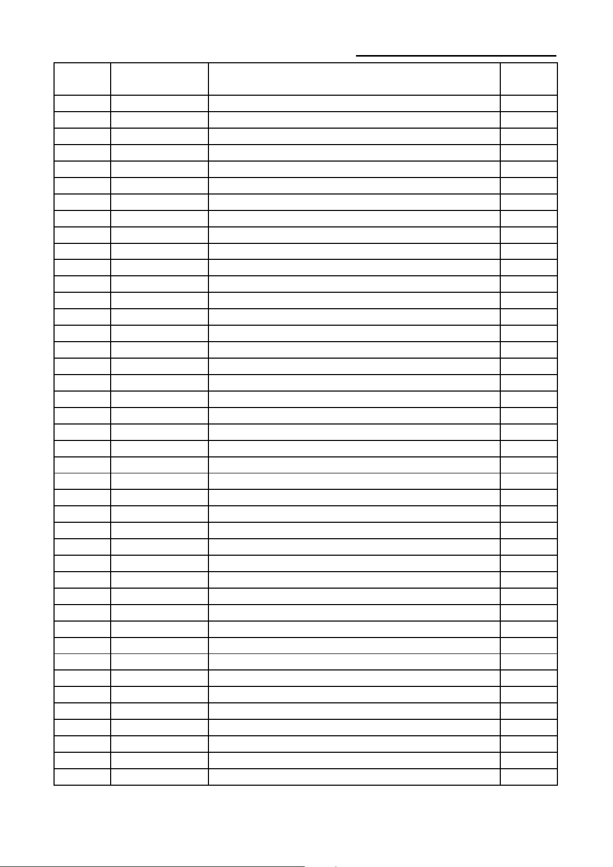
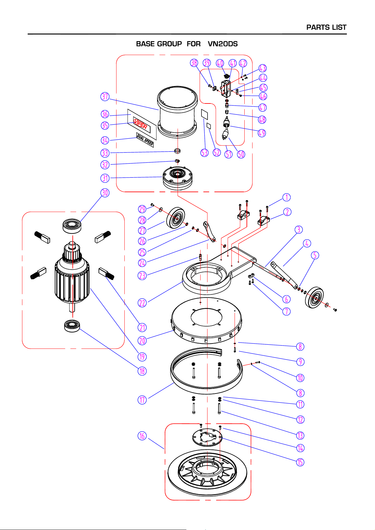
HANDLE GROUP FOR VN20DS
,
,
DIA
NO
1 VF30016 HANDLE RELEASE 1
2 VF30015 BOLT,HANDLE RELEASE 1
3 VF30018 WASHER,PLAIN 2
4 VF13503 NUT,LOCK,M8X5.7 1
5 VF30017 SCREW 1
6 VF30014 COVER,HOOK 1
7 VF45125 CORD,HANDLE 1
8 AS41901 PLUG PROTECTOR SMALL MALE 1
9 VF50120A GROMMET 1
10 VF13504 NUT,LOCK,M10 1
11 VF13517 WASHER,PLAIN 1
12 VF14114 SCREW M8X55 1
13 VF30013 HOOK,CORD 1
14 VF13493 SCREW,M6X10 1
15 AS112205 TUBE 1
16 VF44018 LEVER,SOLUTION 1
17 VV13661 SCREW,M4X12 2
18 VF48306 PIN 3
19 VF44016 LEVER,LEFT,SWITCH 1
20 VF45119 CORD,POWER SUPPLY 1
21 AS22009 STRAIN RELIEF,CORD 1
22 VF30108 GASKET,HANDLE,SOLUTION 1
23 VF14223 SCREW,M6X25 2
24 VF14218 SCREW,M6X45 2
25 VF13528 TEETH WASHER,M6 2
26 VF30102 REAR COVER 1
27 VF99010C BREAKER,CIRCUIT 1
28 VF30109 COVER 1
29 GT13013 NUT,M4 3
30 VF48309 CLAMP BLOCK 1
31 VF44017 LEVER,RIGHT,SWITCH 1
32 VF44203 SWITCH ASSY 1
33 VF14212 SCREW M3X25 2
34 VF13527 WASHER,TEETH,M4 1
35 VF13526 SCREW,M4X30 1
36 VF46705 SAFETY BOTTON 1
37 GV40218 SPRING,SAFETY BUTTON 1
38 VF48310 HANDLE GRIP 2
39 VF30101 FRONT COVER 1
40 VF47035A LOGO 1
41 VF13604 WASHER,TEETH,M5 4
42 VF14222 SCREW
PART
NUMBER
DESCRIPTION
M5X12 4
REQ'D
NO
6
Page 7
7
Page 8
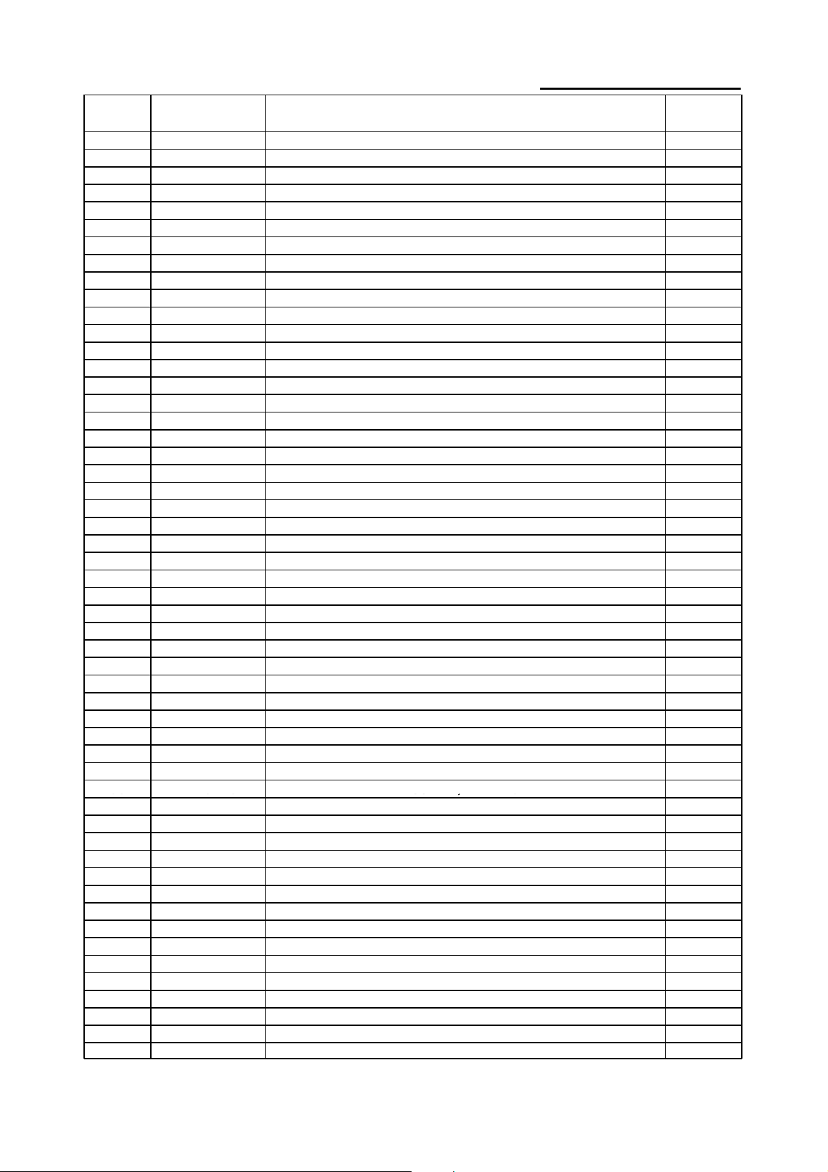
BASE GROUP FOR VN20DS
8
VF13474A
WASHER, PLAIN, M5
4
23
VF40152
HOSE BARB
1
V
38
VA13473
SCREW, M4 X 16
1
46
GT13048
SCREW, M4 X 12
1
V
DIA
NO
1 GT13080 SCREW, M6 X 30 4
2 VF30011 CLAMP BLOCK, HANDLE 1
3 VF30026 AXLE 1
4 VF30020 BRACKET, LEFT HANDLE 1
5 VV20274 WASHER, PLAIN, M13 4
6 GV40235 CLAMP BLOCK, AXLE 2
7 VV13621 SCREW, SELF-TAPPING, ST, M5 X 20 4
9 VF13613 SCREW, M5 X 20 2
10 VA13474 SCREW, M5 X 16 5
11 VF13524 WASHER, PLAIN, M8 4
12 VF13519 WASHER, LOCK, M8 4
13 VF13618 SCREW, 5/16" - 2 1/4" 4
14 MF-VF002-4A SCREW, SELF-TAPPING, 1/4"-1" 6
15 MF-VF002-2 CLUTCH PLATE 1
16 MF-VF022 PAD HOLDER, 19" 1
17 VF30004 BUMPER, 20" 1
18 ZD48315 BEARING, #6002Z 1
19 ZD48200 SHAFT & ROTOR ASSEMBLY 1
20 VF30006 FRAME, 20" 1
21 VF99926-2 KIT, CARBON BRUSH 1
22 VF30008 ALUMINIUM BASE, MOTOR 1
PART
NUMBER
DESCRIPTION
REQ'D
NO
24 VF30019 BRACKET, HANDLE, RIGHT 1
25 VF13520 WASHER, LOCK 2
26 VF50119 WASHER, LOCK, M12 2
27 VF48202 WHEEL, 5" 2
28 VF13666 WASHER, M6 2
29 VF44012 SCREW, M6 X 12.7 2
30 ZD40225 BEARING, #6203Z 1
31
32 VF99021 COULPING 1
33 MT01102 SLEEVE 1
34 VF40990 LABEL, DUAL SPEED 1
35 VF41079 LABEL, VIPER 1
36 ZD48310 LABEL, MOTOR 1
37 ZD48000 MOTOR, DUAL SPEED 1
39 VF44204 RECTIFIER 1
40 VA91347 SWITCH 1
41 ZD48309DY SHELL 1
42 VF13604 WASHER, TOOTH, M5 2
43 VF14214 SCREW, M5 X 8
44 GT13014 NUT, NYLON INSERT, M4
45 ZD48316A TRIAC ASSEMBLY
47 VV67405 STRAIN RELIEF, CORD
48 VV67405-1A NUT
49 AS41902 PLUG PROTECTOR, LARGE, FEMALE
50 VF999794 CORD, MOTOR
51 ZD48330 KIT, SPEED ADJUSTMENT
52 VF40994 READ MANUAL LABEL
53
F999802B GEAR BOX 1
F40997 SERIAL TAG 1
2
2
1
1
1
1
1
1
1
8
Page 9
9
 Loading...