

Page 1
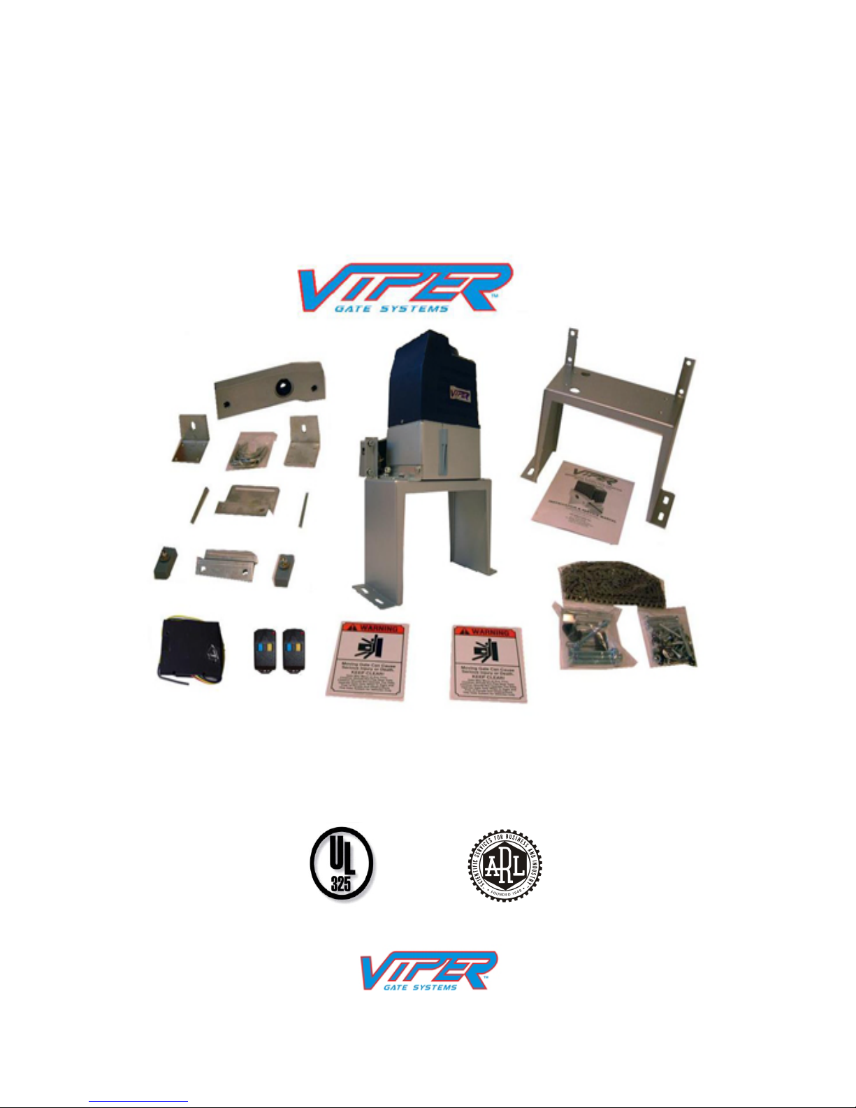
VIPER TC-9
Residential Sliding Gate Opener
(Magnetic Limit Switch – Chain type)
Installation and Owner’s Manual
For Residential use only – Class 1
(A Vehicular gate operator intended for use in a single family dwelling)
Made in the U.S.A.
CAUTION: PLEASE READ THIS MANUAL CAREFULLY
GATEMOTORS INC.
PHONE: (352)241-8259
Email: Sales@Vipergatesystems.com
This Product meets and exceeds the requirements of UL 325, the standard which regulates
gate operator safety, as established and made effective March 1, 2000, by Underwriters Laboratories Inc.
Page 2

TC-9 Viper ™ Gate System
2
Residential Sliding Gate Operator
This page intentionally left blank.
Page 3

TC-9 Viper ™ Gate System
3
Residential Sliding Gate Operator
Table of Contents
Table of Contents................................................................................................................ 3
Safety Alert Symbols .......................................................................................................... 4
Description of your TC-9 Viper Gate Opener .................................................................... 5
FEATRUES .................................................................................................................... 5
SAFETY ......................................................................................................................... 5
SPECIFICATIONS......................................................................................................... 5
OPTION(S) ..................................................................................................................... 6
Packing List .................................................................................................................... 6
Tools you will need............................................................................................................. 7
Installation Instruction ........................................................................................................ 8
Concrete Pad ................................................................................................................... 8
Operator Base.............................................................................................................. 8
Electrical Preparation.................................................................................................. 9
Gate Operator Mechanical Installation ......................................................................... 10
Gate Operator Electrical Installation ............................................................................ 12
Radio Transmitter Controls............................................................................................... 15
Optional Equipment Installation Procedures .................................................................... 20
Adjustment and Maintenance ........................................................................................... 21
Having a Problem?............................................................................................................ 22
Figure 1, Platform Base Dimensions .................................................................................. 9
Figure 2, Viper TC-9 Configuration Diagram .................................................................. 16
Figure 3, Viper TC-9 Control Board Terminals, Indicators and Jumpers ........................ 17
Figure 4 Typical Gate Extension for TC-9 Operator ........................................................ 18
Figure 5 Viper TC-9 Electrical Connection...................................................................... 19
Table 1, Viper TC-9 Specification...................................................................................... 5
Table 2 Viper TC-9 Packing List........................................................................................ 6
Table 3 Required Tools for Installation .............................................................................. 7
Table 4, Security Code Factory Settings........................................................................... 15
Table 5, Security Code New Install .................................................................................. 15
Page 4
TC-9 Viper ™ Gate System
4
Residential Sliding Gate Operator
Safety Alert Symbols
Start here and read these important safety rules for the TC-9 Viper Gate Opener
These safety alert symbols mean CAUTION – Personal safety, property damage
or danger from electrical shock. Read these instructions carefully
Failure to comply with the following instructions may result in serious injury,
including death or property damage. The TC-9 Viper Gate Opener is designed
and tested to provide reasonably safe service if properly installed and operating
in accordance the instructions provided in this Installation Manual
.
Electrical
Hazard
Caution
Caution
Caution
Electrical
Hazard
Installation and wiring must be in compliance with your local building and
electrical safety codes. Connect the power to the TC-9 Gate opener from a
properly grounded electrical outlet. If using electrical conduit to provide
power, be sure to attach the ground conductor to the TC-9 Frame and the
ground terminal on the circuit board.
Activate the opener only when the gate is in full view and free of
obstructions.
Do not allow children to operate the gate opener using any remote
transmitter or push button switch operators. Serious injury from closing
the gate may result from misuse of the opener.
Do not allow children to play near the gate opener. No one should enter or
leave through the gate while it is opening or closing.
Fasten the CAUTION LABEL near the TC-9 Gate Opener and push button
switch operators as a reminder of safe operating procedures.
Do not wear loose clothing, watches or rings while installing or servicing
the gate opener.
Keep your hands away from the gear box, chain and gate track rollers
during operation.
Do not use force to make adjustments or compensate for binding or
sticking gate operation.
Disconnect all electrical power before making repairs or removing the
cover on the TC-9 Opener
Page 5

TC-9 Viper ™ Gate System
5
Residential Sliding Gate Operator
Description of your TC-9 Viper Gate Opener
FEATURES
Weather proof casing
Reliable magnetic limit switches for accurate open and close gate positions.
Self-locking gear motor in both o
Two channel 300 mhz receiver.
Auto-clos
2 year limited warranty on motor
1 year limited warranty on manual & electric parts
e (12.5,25, and 45 second delay)
SAFETY
Electric Safety monitor will stop and reverse gate to open position if it senses an
obstruction while gate is closing.
Release-key to open gate manually in case of an emergency (ie: power failure, fire, etc.).
Electronic anti-entrapment system, operable in both the open
Enclosed chain cover for added protection.
pen and close positions.
and closing directions.
SPECIFICATIONS
Table 1, Viper TC-9 Specification
Motor Safety
Type Permanent split
capacitor,
Speed 1470 RPM Electronic Independent up/down
Volts 120 VAC ± 10% 60 Hz Electrical Motor overload
Current Less than 6 Amps Start Circuit 24 V push button or
Operating Temp.
Torque 15 N.m maximum
Drive Mechanism Dimension
Gears 1:30 Ratio Length (overall) N/A
Drive Chain gear type Ship Weight 58 lbs.
Length of Travel 35 ft max. by magnetic
Travel Rate 1 ft per second. Gate Size 35 ft. (Maximum)
-22/158F (-30/70C)
Limit Switch
Personal Push button remote,
auto reversal
force adjustment
protection
remote sensor.
Emergency Clutch release Key
Chain Length 20 ft. (supplied), ANSI
chain No. 41
Gate Weight (max.) 1200 lbs. (Maximum)
Page 6
TC-9 Viper ™ Gate System
6
Residential Sliding Gate Operator
TC-9
Page 7

MODEL: TC-9
7
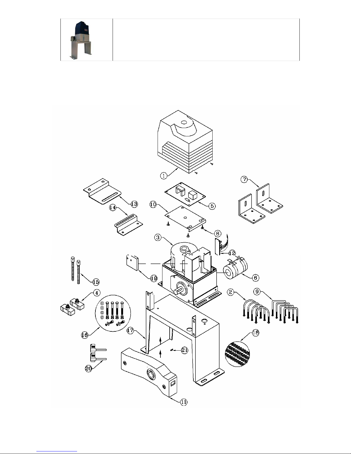
COMPONENT
DESCRIPTION
1
2
3
4
5
6
7
8
9
10
11
12
13
14
15
16
17
18
19
20
21
Base plate for control board
Large bracket for magnet (open limit)
Small bracket for magnet (close limit)
U – bolts
¾ h.p. Motor
Limit magnets
Control board
Capacitor
L – brackets
Plastic clip
Square U- bolts
Chain guard
Receiver
Chain bolts
Spare nuts & bolts bag
Mounting base
10 ft. chain
Limit switch sensor
Manual release keys
Shaft key
Cover
COMPONENT
MANUFACTURER
Viper Gate Systems
Viper Gate Systems
Viper Gate Systems
Viper Gate Systems
Viper Gate Systems
Viper Gate Systems
Viper Gate Systems
Viper Gate Systems
Viper Gate Systems
Viper Gate Systems
Viper Gate Systems
Viper Gate Systems
Viper Gate Systems
Viper Gate Systems
Viper Gate Systems
Viper Gate Systems
Viper Gate Systems
Viper Gate Systems
Viper Gate Systems
Viper Gate Systems
Viper Gate Systems
MFR’S PART NO. QUANTITY
tc9cov1
tc9ub2
tc9mot3
tc9lm4
tc9cb5
tc9cap6
tc9lb7
tc9pc8
tc9sub9
tc9bp10
tc9cg11
tc9rec12
tc9lbol13
tc9sbcl14
tc9cb15
tc9nb16
tc9mb17
tc9ch18
tc9ls19
tc9keys20
tc9sk21
1
4
1
2
1
1
2
4
4
1
1
1
1
1
2
1
1
1
1
2
1
Page 8

TC-9 Viper ™ Gate System
8
Residential Sliding Gate Operator
Tools you will need
During assembly and installation of your opener, the instructions will call for the use of
various tools shown below. Other tools may be required as needed for the installation of
the concrete pad and electrical connection.
Table 3 Required Tools for Installation
Screwdriver Tape Measure Electric Drill Level
File Wrenches Multimeter Pliers Allen Wrenches
Wire Strippers Wire Cutter Adjustable Wrench Socket Wrench
Page 9

MAIN BOARD / TERMINAL BLOCK
Instal
l
18)
#19)
#20)
45 1918367 1110 13 14 20
er. #7)
er. #6)
22
l
ation D
i
ter. #10)
ter. #14)
r. #11)
(ter. #13)
RED
(ter.
#
WHITE (ter
.
BLUE (ter
.
Either wire (
t
Either wire (
t
i
agram
f
4)
3)
#5)
BLACK
(
BLUE (
RED (t
e
YELLOW
f
or your
V
BLUE (ter.
#
BLACK (ter.
#
BROWN (ter.
CAPACITOR
RECEIVE
R
LIMIT
SWITCH
V
iper C
o
YELLOW / GREEN – Ground (ter. #22)
o
ntrol B
o
MOTOR
o
ard.
9
Page 10

TC-9 Viper ™ Gate System
10
Residential Sliding Gate Operator
Installation Instruction
Concrete Pad
The concrete pad for the TC-9 operator should be approximately 24” x 12” x 18” deep.
This will insure a firm stable base to support the torque required in opening/closing the
gate. The pad may be installed at ground level, or up to 3” above the finished grade. Be
sure the base concrete pad is level. The pad should be positioned so it does not interfere
with the gate movement.
You can use the concrete anchors provided with the operator to secure the Platform Base
to the concrete pad. They consist of 3-¾” Anchor Bolts (4), Anchors, Washers and Nuts
(in the same bag with the Manual Clutch Release Key). Anchors must be set into the
concrete at the time of pouring, or you can use 5/16” Lead Sink anchors and lag screws
(not supplied) by drilling four holes into the concrete pad after it has set up.
Operator Base
Position the Viper TC-9 platform on top of the pad, then mark the hole positions (3” OnCenter) which will allow ±¾” of adjustment for proper alignment of the Operator with
the correct distance from the gate, See Figure 1, Platform Base Dimensions. This
alignment is very important so take care in measuring. The platform base should be not
less than 2-¼” from the gate, See Figure 2, Viper TC-9 Configuration Diagram. Again,
be sure the base is properly leveled. Use washers as shims under the platform to assist in
leveling the base.
Page 11

TC-9 Viper ™ Gate System
11
Residential Sliding Gate Operator
Figure 1, Platform Base Dimensions
Electrical Preparation
Install a suitable electrical outlet box that will be used to supply power to the TC-9
Operator. This box should be located near the operator, approx. 24” from the platform,
and out of the path of the gate. Wire size should be 12 gauge two conductor wires with a
Ground and protected by a Ground Fault Circuit Interrupt (GFCI). This can be achieved
by using a GFCI receptacle outlet and connecting the Gate Opener to the LOAD terminal
of the outlet.
If using electrical PVC Water Tight Conduit, See Figure 5, measure a sufficient length of
wire to reach from the Electrical box through the Platform Base hole and 24” inches past
the conduit fitting. This will allow enough wire to feed the wire up into the Operator and
connect to the Circuit Board. Do not connect the cable at this time.
9
Page 12

TC-9 Viper ™ Gate System
12
Residential Sliding Gate Operator
As an option, a standard three prong cord (minimum 14 gauge), suitable for use in a harsh
environment, can be connected into the Outdoor Box protected with a GFCI receptacle.
If using this configuration, be sure to install a weather proof cover on the Outdoor
Electrical box to protect the GFCI receptacle from moisture. These are available at any
hardware store. As a general rule, the cord should be less than six feet in length,
Gate Operator Mechanical Installation
The Viper TC-9 Gate Operator is easily installed for a sliding gate, either left-hand or
right-hand opening. The instructions that follow are for a typical installation, and provide
a fair amount of detail for a complete operating gate opener. In some circumstances
modifications are required to the gate in order to position the operator correctly and
attach the chain to the rear of the gate. This configuration will be discussed in detail
under Optional Mechanical Installation.
Follow the steps below for installation of the Gate Operator.
1. Remove the Viper TC-9 Operator from its packing and check all items against the
Packing List in Table 1.
2. Insert the manual Clutch Release Key into the back of the operator, by pivoting the
key cover to the left and exposing the key hole.
3. Turn the key counter clock wise to disengage the clutch (until it stops, use gentle
force).
4. Install the Chain Box on to the Platform base using the 4 5/8” Socket Head Cap bolts,
finger tight.
5. Install the Angle Iron brackets to the Operator using the four ½ bolts. Tight with
wrench.
6. Attach the Electrical Conduit to the Platform Base using the Fitting nut, tighten as
required. Caulk the conduit fitting and wire with suitable Silicone caulking to prevent
any water or moisture from entering the electrical conduit.
7. Remove the tape from the motor shaft holding the sprocket shear key.
8. Apply a small amount of WD-40 or other lubricant onto the shear key and drive shaft.
9. Remove the operator cover (three Phillips head screws).
10. Carefully thread the Electrical wires through the hole in
and route the cables up to the circuit board. Be extremely careful not to fray the
insulation on the wire. Do not connect the electrical at this time.
11. Position the Operator in front of the Chain Box and align the shaft and shear key with
the Chain Box sprocket and insert the shaft into the sprocket.
12. Install the 4 5/8” Socket Head Cap bolts through the Angle Iron brackets that hold the
Operator to the Base, finger tight.
13. Tighten the Chain Box bolts to the base with a wrench.
14. Position the Operator and Chain Box approximately one half inch (½”) from the Gate
as measured from the front of the Chain Box to the gate, see Figure 1.
15. Install the four bolts securing the Opener to the Base, and tighten with wrench.
the bottom of the operator,
Page 13

TC-9 Viper ™ Gate System
k
13
Residential Sliding Gate Operator
16. Install the two Chain bolts, U-bolt clamps and brackets to the gate as illustrated in
Figures 1 & 4. One is installed on the right side of the Gate, the other on the left side,
preferable on the outer gate frame. They should be positioned at the same height as
the chain that exits the Chain Box.
17. For the next steps, be sure the gate is in the closed position.
18. Connect the 10 Foot chain to the short chain that exits the Chain Box using the Chain
Master Link.
19. Stretch the chain along the ground to the front end of the gate (furthest from the Gate
Opener while the gate is closed.
20. Hold on to the short length of chain that exits the Chain Box near the rear end of the
Gate, and cut and remove the two wire ties that hold the chain inside the Chain Box.
Be sure to remove the Wire Tie debris.
21. Pull as much chain as needed to connect the chain to the Chain Bolt install on the rear
of the gate frame, and attach to the chain bolt using a Master Link (see Figure 1).
Note: Clutch is loose so you should be able to pull the chain through the Chain Box.
22. Stretch the chain to the front end of the gate U-Bolt and mark the chain link that will
be cut which allows enough slack for adjusting the tension of the Chain.
23. You will now have to remove the long length of chain at the Master Link at the short
chain near the Chain Box. This will facilitate in cutting the link at the proper place.
24. Cutting the Chain:
A. Place the long chain in a vice or clamp to a stable support at the link marked.
B. File off the rivet at the inner link, see picture below.
C. Using a punch, remove the link pin and discard the unused chain.
File off Chain Rivet here
Punch out pin
.
25. Install the chain with a master link to the Chain Box short chain.
26. Stretch the chain to the Chain Bolt and install with a Master Link.
Discard links
Master Lin
11
Page 14

TC-9 Viper ™ Gate System
14
Residential Sliding Gate Operator
27. Adjust and tighten the Chain Bolt allowing for a 3” sag in the chain spanning the
length of the gate.
28. With the Chain Box Clutch loose, move the gate open and closed. It should slide
smoothly.
29. Install the Magnetic Limit magnets on both ends of the gate. On the opening side of
the gate, the “Open” Magnet is in the Upper position, while the tail end of the gate the
“Close” Magnet is in the Lower position. See Figure 2. Manually open and close the
gate to determine where the magnets are to be mounded on the Gate.
30. Adjust the Magnets so there is ½” clearance from the Magnet to the Gate Opener.
31. Mechanical installation of the Gate Operator is Complete
Gate Operator Electrical Installation
The National Electric Code requires proper electrical connections in wet
locations (outdoors) for all electrical equipment.
The procedures that follow assume that a suitable 120 V AC GFCI Outlet receptacle with
a weatherproof cover is located near the Gate Opener (as shown in Figure 5) that can be
used to connect the Electrical Power to the Viper TC-9 Gate Operator. Please follow the
manufactures installation guide for installing and testing a GFCI receptacle.
1. Ensure that the electricity to the Outlet Box is OFF.
2. Check the Power switch on the Viper Control Board. Switch to the OFF position
“O/I” with “O” switch position down).
3. With the Viper TC-9 Cover removed, connect the Ground (Green Wire or bare copper
wire) to a Grounding Pigtail.
4. Attach the other end of the Pigtail to the Motor bolt by loosen the bolt using a 5mm
Allan Wrench, then re-tighten. This will provide a suitable Grounding, see picture
below.
5. Connect the Black wire to Terminal 1 and the Neutral White wire to Terminal 2
of the Viper Control Board. Terminal identifications are shown in Figure 3, Viper
TC-9 Control Board Terminals, Indicators and Jumpers.
6. At the Outlet Box, connect the wires to the 120 V AC GFCI receptacle Load
terminals.
7. Reinstall the receptacle into the Outdoor Box and attached the faceplate cover.
8. Turn on the Power to the GFCI Outlet Box, and test the GFCI in accordance with the
manufactures instruction. If the circuit us functioning properly, proceed to the next
step. If not, recheck the GFCI receptacle installation and isolate the problem.
9. On the Viper TC-9 Control board, turn on the Power Switch by pressing the switch to
the “I” position down.
10. Verify that the Power indicator (31) on the Control Board is lit. See Figure 3.
Page 15

TC-9 Viper ™ Gate System
15
Residential Sliding Gate Operator
11. Manually open the Gate and observe the OPEN Indicator (26) on the Control Board.
If the indicator dose not light up, then adjust the Upper Magnet until the indicator
lights. Tighten with a wrench.
12. Manually close the Gate and observe the CLOSE indicator (27) on the Control
Board. If the indicator dose not light up, then adjust the Lower Magnet until the
indicator lights. Tighten with a wrench.
13. Before tightening the Operator Clutch with the key, test the gate opener with the
remote supplied. Press the Yellow button on the remote and listen for the motor
running. Pressing the Yellow button again, the motor will stop.
14. If the gate motor is operating, properly, then insert the Clutch Key, rotating it
clockwise until it stops. The Gate Operator is now ready for testing.
15. Using the Remote, press the Yellow button and the gate will open. Pressing the
yellow button again, the gate should stop moving.
16. Now test the full operation of the gate. Pressing the remote yellow button will cause
the gate to move until the Magnet is positioned over the Limit Senor. The gate
should now be closed.
17. Pressing the Remote Yellow Button again, the gate should open, and stop when the
Upper Magnet is positioned over the Limit Sensor. The Gate should be in the full
open position.
18. Your Viper Gate Installation is now complete. Now proceed to the Radio Transmitter
Control section to program the Security codes for the operator.
Optional Mechanical Installation
In some installation of the Viper TC-9 Gate Operator, positioning of the operator itself
may extend beyond the rear of the gate. This type of installation would require an
extension or “tail” to be added to the gate to accommodate the installation of the rear
chain bolt to the gate. This is illustrated in Figure 4, Typical Gate Extension for TC-9
Operator. It would require wielding or attaching an extension to the gate. In this case,
the minimum extension must extend 8” beyond the Chain Box to allow sufficient chain
slack and clearance. A wielding shop can configure a simple bolt on extension from a
drawing with required measurement. The picture below is an actual installation with this
configuration.
13
Page 16

TC-9 Viper ™ Gate System
16
Residential Sliding Gate Operator
In this configuration, the tail extension was made from the same material as the gate, 1½” square tubing, and is 12” long and 10” high. At the right side, the chain bolt plate
was wielded on at the shop as were the two U clamps that attach the extension to the gate
(left). A piece of angle iron was used to support the closing magnet, and mounting holes
were drilled (4) ½ inches apart that allows for the magnet adjustment. Two bolts were
used to attach the angle iron to the extension.
14
Page 17

Receiver/RemoteControlInstructions
1.
Whenpowerisongreenlightonreceivershouldlightup
2
thenletgo.(atthispointremoteis
Whenpowerison
greenlightonreceiver
shouldlightup
2. PushLearnbuttonandredlightcomeson
3. Choose1outofthe4buttonsontheKeyChainRemote
Control.
4. Pressthenumberthatyouchosetobeyourbuttonuntil
theredlightonreceiverisoffandthenletgo
5. Pressthenumberbuttonthatyouhavechosenonthe
remoteagain.Redlightblinksrapidlythenletgo(atthis
pointremoteisprogrammedtoyourreceiver)
6. Finally,Pressthebuttonforthethirdtimeyoushouldget
aresponsethatmeansthegateopenerisworking.
1
2
Pushlearnbuttonred
lightcomeson
Pressthenumberthatyou
chosetobeyourbuttonuntil
theredlightonreceiverisoff
andthenletgo
Pressthenumberbuttonthatyouhavechosen
ontheremoteagain,Redlightblinksrapidly
programmedtoyourreceiver)
Finally,Pressthebuttonforthethirdtimeyou
shouldgetaresponsethatmeansthegate
openerisworking.
Choose1outofthe4
buttonsontheKey
ChainRemoteControl
4
3
5
6
**Remotecontrol
stylemightvary
Page 18

TC-9 Viper ™ Gate System
18
Residential Sliding Gate Operator
-
2. Using a small Phillips screwdriver, open the remote and set the DIP switches to the
corresponding setting from the Gate Operator noted in Table 5.
3. Press the Remote Yellow button and verify that the new selected codes operate the
gate.
4. Replace TC-9 Viper Gate Opener plastic cover and secure with the three screws.
5. Your Gate radio transmitter controls setting are complete.
Figure 2, Viper TC-9 Configuration Diagram
16
Page 19

TC-9 Viper ™ Gate System
20
Residential Sliding Gate Operator
Figure 4 Typical Gate Extension for TC-9 Operator
Page 20

TC-9 Viper ™ Gate System
21
Residential Sliding Gate Operator
Figure 5 Viper TC-9 Electrical Connection
Page 21

TC-9 Viper ™ Gate System
22
Residential Sliding Gate Operator
Page 22

TC-9 Viper ™ Gate System
23
Residential Sliding Gate Operator
Adjustment and Maintenance
The following should be done periodically.
1. Check the wiring and operation of the GFCI Receptacle per the manufactures
procedures.
2. Apply a light coat of oil on the chain. Check for smooth operation (monthly).
3. Tighten Bolts on the Gate and Platform.
4. Verify that the Safety IR Beam Sensor operates correctly.
5. Verify that the Gate Limit Switches are in the correct position for Open and
Closed operations.
6. Disengage the Clutch using the Clutch Key. Check to see that the Gate can be
opened and closed manually. Note: Keep the Clutch Key near the Opener so
you can locate it easily if there is a power failure. Attach the Clutch Key to
the GFCI outlet box that is nearby.
7. Change the Security Codes Yearly in both the Viper Control Board and the
Remote Openers.
Page 23

TC-9 Viper ™ Gate System
24
Residential Sliding Gate Operator
Having a Problem?
Situation Probable Cause & Solution
Opener does not operate
from remote
Gate Opener operates then
stops
Gate will not stop at the
designated position
Is the gate locked?
Does the operator have electrical power? Check the
electrical outlet for power.
Remove the Viper TC-9 cover and check the power
indicator light 31.
Check for obstruction in the Sensor Beam path
Check the Fuse 33 with an ohm meter.
Verify that the Clutch Key is tight.
Verify the DIP switch Security Codes are correct.
Replace the Remote Battery.
Adjust the Obstruction Sensor and decrease the sensitivity
Release the Clutch using the Clutch Key. Manually move
the gate to see that it slides freely.
Check the chain for tightness. There should be about 3” of
sag in the chain across the gate.
Check the Open Magnet to ensure it is in the proper place.
Remove the Viper cover and release the Clutch using the
Clutch Key. Manually operate the gate and check the
Indicators 26 for Open, and 27 for Close.
Reposition the Magnets as needed to correct the operation.
22
Page 24

TC-9 Viper ™ Gate System
25
Residential Sliding Gate Operator
Limited Warranty
You must read, understand and agree with items in the Limited
Warranty.
GATEMOTORS INC. Warrants the Sliding Gate Operator to be free of
defects in workmanship and materials for a period of 1 year for electronics, mechanical
components and chassis for perforation due to corrosion and 2 year warranty on motor.
GATEMOTORS INC reserves the right of final determination as to the existence and
causes of any defect or failure. Any part or parts found to be defective and are returned to
GATEMOTORS INC within the warranty period, shall at our option be repaired or
replaced free of charge F.O.B. the factory.
The warranty will not apply the following circumstances, which are considered beyond
our control. Mis-use, vandalism, accident, neglect, unauthorized repairs or modifications,
acts of God (lightning, floods, insect damage, etc..), power surges, units subjected to
corrosive environments, incorrect installation or application, damage to mechanism due
to wrong type of gate, incorrect weight, gate not operating freely or not on level ground.
The warranty set forth above is entirely exclusive and no other warranty whether written
or oral, is expressed or implied. GATEMOTORS INC. specifically disclaims any and all
implied warranties, merchantability or fitness for a particular purpose. It is the
purchaser’s sole and exclusive responsibility to determine whether or not the equipment
will be suitable for a particular purpose. In no event shall GATEMOTORS INC. be held
liable for direct, indirect, incidental, special, consequential damages or loss of profits
whether based on contract, tort, or any other legal theory during the course of the
warranty or at any time there after. The installer and/or end user do agree to assume all
responsibility for all liability in use of this product, releasing GATEMOTORS INC. of all
liability.
IN ORDER TO INSTALL AND USE THE SLIDING GATE
OPERATOR, YOU MUST UNDERSTAND AND BE IN FULL UNCONDITIONAL
AGREEMENT WITH ALL STIPULATIONS OUTLINED ABOVE. IF YOU ARE
NOT IN FULL AGREEMENT, DO NOT PUT UNIT INTO OPERATION. IF
OPERATOR IS PUT INTO OPERATION THIS WILL BE CONFIRMATION
THAT YOU ARE IN FULL UNCONDITIONALL AGREEMENT WITH ALL OF
THE ABOVE STIPULATIONS.
23
 Loading...