

Page 1

Residential Sliding Gate Opener
(Magnetic L i m it Switch – Chain type)
Installation and Owner’s Manual
For Residential use only – Class 1
( A Ve hic ula r ga t e op e r a tor int e nd e d for use in a s ingle f a m i l y dwe l l i n g )
Made in the U.S.A.
: N O I T U A C E S A E L P D A E R S I H T L A U N A M Y L L U F E R A C
GATEMOTORS INC.
Email: GATEMOTOR@YAHOO.COM
WWW.GATEMOTORS.COM
This Product meets and exceeds the requirements of UL 325, the standard which regulates
gate operator safety, as established and made effective March 1, 2000, by Underwriters Laboratories Inc.
Page 2

Residential Sliding Gate
Operator
Table of Contents
Table of Contents................................................................................................................ 1
Safety Alert Symbols .......................................................................................................... 4
Description of your Gate Opener ....................................................................................... 5
FEATRUES .................................................................................................................... 5
SAFETY ......................................................................................................................... 5
SPECIFICATIONS......................................................................................................... 5
OPTION(S) ..................................................................................................................... 6
Packing List .................................................................................................................... 6
Tools you will need............................................................................................................. 7
Installation Instruction ........................................................................................................ 8
Concrete Pad ................................................................................................................... 8
Operator Base.............................................................................................................. 8
Electrical Preparation.................................................................................................. 9
Gate Operator Mechanical Installation ......................................................................... 10
Gate Operator Electrical Installation ............................................................................ 12
Radio Transmitter Controls............................................................................................... 16
Optional Equipment Installation Procedures .................................................................... 23
Adjustment and Maintenance ........................................................................................... 24
Having a Problem?............................................................................................................ 25
Figure 1, Platform Base Dimensions .................................................................................. 9
Figure 2, Configuration Diagram ..................................................................................... 18
Figure 3, Control Board Terminals, Indicators and Jumpers ............................................ 19
Figure 4 Typical Gate Extension for Operator.................................................................. 21
Figure 5 Electrical Connection.......................................................................................... 22
Table 1, Specification.......................................................................................................... 5
Table 2 Packing List........................................................................................................... 6
Table 3 Required Tools for Installation .............................................................................. 7
Table 4, Security Code Factory Settings........................................................................... 16
Table 5, Security Code New Install .................................................................................. 16
1
Page 3
Residential Sliding Gate
Operator
2
Safety Alert Symbols
Start here and read these important safety rules for the SLIDE Gate Opener
These safety alert symbols mean CAUTION – Personal safety, property damage
or danger from electrical shock. Read these instructions carefully
.
Failure to comply with the following instructions may result in serious injury,
including death or property damage. The SLIDE Gate Opener is designed
and tested to provide reasonably safe service if properly installed and operating
in accordance the instructions provided in this Installation Manual
Electrical
Hazard
Installation and wiring must be in compliance with your local building and
electrical safety codes. Connect the power to the SLIDE Gate opener from a
properly grounded electrical outlet. If using electrical conduit to provide
power, be sure to attach the ground conductor to the SLIDE Frame and the
ground terminal on the circuit board.
Caution
Activate the opener only when the gate is in full view and free of
obstructions.
Do not allow children to operate the gate opener using any remote
transmitter or push button switch operators. Serious injury from closing
the gate may result from misuse of the opener.
Caution
Do not allow children to play near the gate opener. No one should enter or
leave through the gate while it is opening or closing.
Fasten the CAUTION LABEL near the SLIDE Gate Opener and push button
switch operators as a reminder of safe operating procedures.
Caution
Do not wear loose clothing, watches or rings while installing or servicing
the gate opener.
Keep your hands away from the gear box, chain and gate track rollers
during operation.
Do not use force to make adjustments or compensate for binding or
sticking gate operation.
Electrical
Hazard
Disconnect all electrical power before making repairs or removing the
cover on the SLIDE Opener
Page 4

Residential Sliding Gate
Operator
3
Description of your SLIDE Gate Opener
FEATRUES
• Weather proof casing
• Reliable magnetic limit switches for accura te open and close gate positions.
• Self-locking gear motor in both open and close positions.
• 300 mhz receiver.
• 2 year limited warranty on motor
• 1 year limited warranty on manual & electric parts
SAFETY
Electric Safety monitor will stop and reverse gate to open position if it senses an
obstruction while gate is closing.
• Release-key to open gate manually in case of an em ergency (ie: power failure, fire, etc.).
• Electronic anti-entrapment system, operable in both the open and closing directions.
• Enclosed chain cover for added protection.
SPECIFICATIONS
Table 1, SLIDE GATE OPENER Specification
Motor Safety
Type Permanent split
capacitor, oil bath
Personal Push button remote,
auto reversal
Speed 1470 RPM Electronic Independent up/down
force adjustment
Volts 120 VAC ± 10% 60 Hz El ectrical Moto r overload
protection
Current Less than 6 Amps Start Circuit 24 V push button or
remote sensor.
Operating Temp.
-22/158 ° F (-30/70 ° C)
Emergency Clutch release Key
Torque 15 N.m
maximum
Drive Mechanism Dimension
Gears 1:30 Ratio Length (overall) N/A
Drive Chain gear type Ship Weight 58 lbs.
Length of Travel 25 ft max. by magnetic
Limit Switch
Chain Length 25 ft.MAX, ANSI
chain No. 41
Travel Rate 11” per second. Gate Size 25 ft. (Maximum)
Gate Weight (max.) 800 lbs. (Maximum)
Page 5
SLIDE GATE OPENER
4
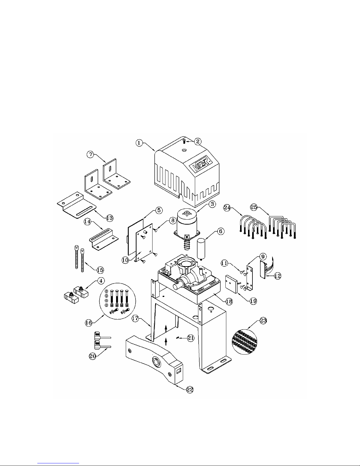
Page 6

MODEL:
COMPONENT
DESCRIPTION
COMPONENT
MANUFACTURER
MFR’S PART NO. QUANTITY
1
2
3
4
5
6
7
8
9
10
11
12
13
14
Cover
Set Phillips screw
1/2 h.p. Motor
Limit magnets
Control board
Capacitor
L-brackets
Plastic clip
Base plate for receiver/
limit switch sensor
Base plate for control board
Plastic clips
Receiver
Large bracket for magnet (open limit)
Small bracket for magnet (close limit)
VIP
VIP
VIP
VIP
VIP
VIP
VIP
VIP
VIP
VIP
VIP
VIP
VIP
VIP
tc3cov1
tc3sps2
tc3mot3
tc3lm4
tc3c/b5
tc3cap6
tc3lb7
tc3pc8
tc3bp9
tc3bp10
tc3pc11
tc3rec12
tc3lbol13
tc3sbcl14
1
1
1
2
1
1
2
4
1
1
4
1
1
1
15
16
17
18
19
20
21
22
23
24
25
Chain bolts
Spare nuts & bolts bag
Mounting base
Motor housing
Limit switch sensor
Manual release keys
Shaft key
Chain guard
10 ft. chain
U- bolts
Square U-bolts
VIP
VIP
VIP
VIP
VIP
VIP
VIP
VIP
VIP
VIP
VIP
tc3cb15
tc3nb16
tc3mb17
tc3mh18
tc3ls19
tc3keys20
tc3sk21
tc3cg22
tc3ch23
tc3ub24
tc3sub25
2
1
1
1
1
2
1
1
1
4
4
5
Page 7

Residential Sliding Gate
Operator
6
Tools you will need
During assembly and installation of your opener, the instructions will call for the use of
various tools shown below. Other tools may be required as needed for the installation of
the concrete pad and electrical connection.
Table 3 Required Tools for Installation
Screwdriver Tape Measure Electric Drill Level
File Wrenches Multimeter Pliers Allen Wrenches
Wire Strippers Wire Cutter Adjustable Wrench Socket Wrench
Page 8

Step #2
Install the Control Board onto the Motor by mounting it on the
Step #3
Install the Receiver onto the Motor by mounting it on the small
(as shown
Step #1
Unscrew the Blue Cover from the Motor and set it aside.
Open the small white box & make sure that the contents include:
(1) - Receiver and (1) - Control Board
small white clips that are on the large Mounting Plate.
(as
shown below)
white clips that are on the small Mounting Plate.
below)
7
Page 9

Step #4
Next, take the set of wires coming from the motor and connect the
red and black wires anywhere onto the plug.
Once you have connected those wires, you will then take that plug
and connect it to the Control Board on the section labeled:
MAKING THE CONNECTION
Now you will begin the installation by screwing the wires that are coming
from the small Receiver Board onto the Terminals (see Pic 1, right) from
the Control Board, in the following order:
Terminal 10 - GREEN WIRE
Terminal 11 - RED WIRE
Terminal 12 - YELLOW WIRE (any)
Terminal 13 - YELLOW & BLUE WIRE (any )
Terminal 14 - BLUE WIRE (any)
Step #5
(as shown on the pic, right)
Pic 1
"MOTOR"
(as shown on the pic, right)
8
Page 10

Step #6
Find the plug with the Blue & Yellow wires on it. Connect the plug on
Step #7
Find the plug with the Red, White & Blue wires on it. Connect the plug
Step #8
Step #9
You are now ready to connect you power wires to your Gate
Opener!
to the Control Board on the section labeled:
"CAPACITOR"
(as shown on the pic, right)
on to the Control Board on the section labeled:
"LIMIT SWITCH"
(as shown on the pic, right)
Find the wire coming from the bottom of the Motor that is GREEN &
YELLOW. Screw the "Ground Wire" to Terminal #22 on the Control
Board
(as shown on the pic, right)
Terminal #1 - POWER
Terminal #2 - NEUTRAL
9
Page 11

AC SLIDE GATE CONTROLLER
FEATURE SELECTOR
Limit Switch Type
ON: Normally Close
OFF: Normally Open
When using auto close features
DIP 1
10
Auto Close Feature
12.5 Seconds
25 Seconds
45 Seconds
only one
di
p sw
itch sh
ou
ld
b
e
ON. The other two dip switch
should be in the OFF posion for
the auto close feature to work
correctly.
DI P 2
DI P 3
DI P 4
Direcon of Gate
ON: Gate Opening to the le
OFF: Gate Opening to the Right
NOT USED
DI P 5
DI P 6
Receiver
Channel One (not used at this me)
Channel Two (not used at this me)
DI P 7
DI P 8
Page 12

SLIDING GATE OPERATOR
11
Anchors
You can use the anchors that are provided with the operator, 3 ¾ anchor bolts (4), anchors,
washers, and nuts. These anchors must be set into the concrete when it is poured, or you
can use wedge anchors (1/4” x 4”).
Operator Base
Mount the gate operator base to the concrete pad. The distance between the gate and the
base should be no more than 2 ½ “ (64mm). Verify that the operator is leveled properly.
Nut
Anchor
Cable
Anchor bolt
Conduit
Chain box
Socket head cap screw
Concrete pad
Gate operator
Operator base
Fig.2
Chain Box
Make sure the ends of the guide chain are out of the chain holes on both sides of the chain
box. Remove the cover and insert the manual release key and turn counter-clockwise to
disengage the clutch. Remove the elastic band from the shaft and line up the key on the
shaft with the sprocket at the chain box. Insert the sprocket from the chain box into the
operator shaft. Place the operator on top of the base and use (4) 5/8 “ (M8x15mm) socket
head cap screws to mount the chain box in to the base.
Operator
Mount the gate operator to the base using (4) 2 ¾ “ (M8x70mm) #48 bolts and washers.
Make sure there is no more than 1/8” (2mm) of space between the cover and the chain box.
Check the operator and make sure it is lined up with the gate.
Page 13

SLIDING GATE OPERATOR
12
Fig.3
Chain Brackets
Use the appropriate bolts to attach the chain bracket to the frame of the gate. If the gate is of
square frame style, use the square bolts shown.
Spring washer (Φ 8)
Plain washer (
Φ 8)
"L" bracket
Square bolt
Nut (M8)
Chain bolt
Master link
Nut (M6)
Spring washer (
Φ 6)
Plain washer (
Φ 6)
Gate
Square frame
Fig.4
If the gate is of round frame style, use the round bolts shown.
Round bolt
"L" bracket
Plain washer (
Ф 8)
Spring washer (
Ф 8)
Nut (M8)
Chain bolt
Master link
Nut (M6)
Spring washer (
Ф 6)
Plain washer (
Ф 6)
Gate
Round frame
Fig.5
Page 14

SLIDING GATE OPERATOR
13
Chain
Close the gate and attach a chain bolt to the piece of chain that comes with the chain box
using enclosure master links. Tighten the chain bolt to the bracket with washers and nuts.
Pull the chain through the chain wheel box to the other chain bracket at the opposite end of
the gate. Connect the other end of the chain and the chain bolt, and then tighten the chain
bolt to the chain bracket. Thread up the chain by adjusting the chain bolt. Cut the chain to
length if necessary. Make sure that the chain is perfectly aligned with the chain holes on the
chain box. Tighten the chain by tightening the chain bolts at either end. See illustration
below.
Master link
Chain bolt
Chain
Fig.6
Magnets for Limit Switch
Install the magnet and magnetic limit switch as shown in Fig.7. The magnet and limit switch
are used to control the position of the gate. When the magnet is installed, release the gear
clutch and push the sliding gate manually to pre-determine the position. Fit the magnet
bracket to the gate and then tighten the gear clutch. The lower bracket is for open position
and higher bracket is for close position. Finally adjust the magnet to the proper position by
moving the gate with the motor. The magnet should be .39 - .59 “away from the magnetic
limit switch. If it is too far away, the switch will fail to work. The distance between the magnet
and the operator should be @ ½” (12mm) with the operator cover on. Adjust the position of
the magnetic limit switch until the positions of the opening and closing meet the requirement.
Important Note: Please note the two magnet brackets (fixed plate) are different: one is
higher and another is lower. Verify and if necessary exchange the two brackets
position. Also if necessary
exchange the limit switch wires CL (close) and OP (open).
Another common problem is there are four reed switches inside the magnetic limit
switch: two are upper and two are lower. The magnet position can be installed in the
middle so it inducts both reed switches. Solution: adjust the magnet upper or lower.
mm5.412
10-15mm
Gate
Nut
Bolt
Spring washer
Plain washer
Magnet bracket
Magnet
Nut
Magnetic limit
switch inside
Gate operator
Fig.7
Page 15

Residential Sliding Gate
Operator
14
Figure 1, Platform Base Dimensions
Electrical Preparation
Install a suitable electrical outlet box that will be used to supply power to the
Operator. This box should be located near the operator, approx. 24” from the platform,
and out of the path of the gate. Wire size should be 12 gauge two conductor wires with a
Ground and protected by a Ground Fault Circuit Interrupt (GFCI). This can be achieved
by using a GFCI receptacle outlet and connecting the Gate Opener to the LOAD terminal
of the outlet.
If using electrical PVC Water Tight Conduit, See Figure 5, measure a sufficient length of
wire to reach from the Electrical box through the Platform Base hole and 24” inches past
the conduit fitting. This will allow enough wire to feed the wire up into the Operator and
connect to the Circuit Board. Do not connect the cable at this time.
Page 16

Residential Sliding Gate
Operator
15
As an option, a standard three prong cord (minimum 14 gauge), suitable for use in a harsh
environment, can be connected into the Outdoor Box protected with a GFCI receptacle.
If using this configuration, be sure to install a weather proof cover on the Outdoor
Electrical box to protect the GFCI receptacle from moisture. These are available at any
hardware store. As a general rule, the cord should be less than six feet in length,
Gate Operator Mechanical Installation
The SLIDE Gate Operator is easily installed for a sliding gate, either left-hand or
right-hand opening. The instructions that follow are for a typical installation, and provide
a fair amount of detail for a complete operating gate opener. In some circumstances
modifications are required to the gate in order to position the operator correctly and
attach the chain to the rear of the gate. This configuration will be discussed in detail
under Optional Mechanical Installation.
Follow the steps below for installation of the Gate Operator.
1. Remove the SLIDE GATE Operator from its packing and check all items against the
Packing List in Table 1.
2. Insert the manual Clutch Release Key into the back of the operator, by pivoting the
key cover to the left and exposing the key hole.
3. Turn the key counter clock wise to disengage the clutch (until it stops, use gentle
force).
4. Install the Chain Box on to the Platform base using the 4 5/8” Socket Head Cap bolts,
finger tight.
5. Install the Angle Iron brackets to the Operator using the four ½ bolts. Tight with
wrench.
6. Attach the Electrical Conduit to the Platform Base using the Fitting nut, tighten as
required. Caulk the conduit fitting and wire with suitable Silicone caulking to prevent
any water or moisture from entering the electrical conduit.
7. Remove the tape from the motor shaft holding the sprocket shear key.
8. Apply a small amount of WD-40 or other lubricant onto the shear key and drive shaft.
9. Remove the operator cover (three Phillips head screws).
10. Carefully thread the Electrical wires through the hole in the bottom of the operator,
and route the cables up to the circuit board. Be extremely careful not to fray the
insulation on the wire. Do not connect the electrical at this time.
11. Position the Operator in front of the Chain Box and align the shaft and shear key with
the Chain Box sprocket and insert the shaft into the sprocket.
12. Install the 4 5/8” Socket Head Cap bolts through the Angle Iron brackets that hold the
Operator to the Base, finger tight.
13. Tighten the Chain Box bolts to the base with a wrench.
Page 17

Residential Sliding Gate
Operator
16
14. Position the Operator and Chain Box approximately one half inch (½”) from the Gate
as measured from the front of the Chain Box to the gate, see Figure 1.
15. Install the four bolts securing the Opener to the Base, and tighten with wrench.
16. Install the two Chain bolts, U-bolt clamps and brackets to the gate as illustrated in
Figures 1 & 4. One is installed on the right side of the Gate, the other on the left side,
preferable on the outer gate frame. They should be positioned at the same height as
the chain that exits the Chain Box.
17. For the next steps, be sure the gate is in the closed position.
18. Connect the 20 Foot chain to the short chain that exits the Chain Box using the Chain
Master Link.
19. Stretch the chain along the ground to the front end of the gate (furthest from the Gate
Opener while the gate is closed.
20. Hold on to the short length of chain that exits the Chain Box near the rear end of the
Gate, and cut and remove the two wire ties that hold the chain inside the Chain Box.
Be sure to remove the Wire Tie debris.
21. Pull as much chain as needed to connect the chain to the Chain Bolt install on the rear
of the gate frame, and attach to the chain bolt using a Master Link (see Figure 1).
Note: Clutch is loose so you should be able to pull the chain through the Chain Box.
22. Stretch the chain to the front end of the gate U-Bolt and mark the chain link that will
be cut which allows enough slack for adjusting the tension of the Chain.
23. You will now have to remove the long length of chain at the Master Link at the short
chain near the Chain Box. This will facilitate in cutting the link at the proper place.
24. Cutting the Chain:
A. Place the long chain in a vice or clamp to a stable support at the link marked.
B. File off the rivet at the inner link, see picture below.
C. Using a punch, remove the link pin and discard the unused chain.
Page 18

Residential Sliding Gate
Operator
17
25. Install the chain with a master link to the Chain Box short chain.
26. Stretch the chain to the Chain Bolt and install with a Master Link.
27. Adjust and tighten the Chain Bolt allowing for a 3” sag in the chain spanning the
length of the gate.
28. With the Chain Box Clutch loose, move the gate open and closed. It should slide
smoothly.
29. Install the Magnetic Limit magnets on both ends of the gate. On the opening side of
the gate, the “Open” Magnet is in the Upper position, while the tail end of the gate the
“Close” Magnet is in the Lower position. See Figure 2. Manually open and close the
gate to determine where the magnets are to be mounded on the Gate.
30. Adjust the Magnets so there is ½” clearance from the Magnet to the Gate Opener.
31. Mechanical installation of the Gate Operator is Complete
Gate Operator Electrical Installation
The National Electric Code requires proper electrical connections in wet
locations (outdoors) for all electrical equipment.
The procedures that follow assume that a suitable 120 V AC GFCI Outlet receptacle with
a weatherproof cover is located near the Gate Opener (as shown in Figure 5) that can be
used to connect the Electrical Power to the SLIDE Gate Operator. Please follow the
manufactures installation guide for installing and testing a GFCI receptacle.
1. Ensure that the electricity to the Outlet Box is OFF.
2. Check the Power switch on the Viper Control Board. Switch to the OFF position
“O/I” with “O” switch position down).
File off Chain Rivet here
Punch out pin
.
Discard links
Master Lin
k
Page 19

Residential Sliding Gate
Operator
18
9. On the SLIDE Control board, turn on the Power Switch by pressing the switch to
the “I” position down.
10. Verify that the Power indicator (31) on the Control Board is lit. See Figure 3.
11. Manually open the Gate and observe the OPEN Indicator (26) on the Control Board.
If the indicator dose not light up, then adjust the Upper Magnet until the indicator
lights. Tighten with a wrench.
12. Manually close the Gate and observe the CLOSE indicator (27) on the Control
Board. If the indicator dose not light up, then adjust the Lower Magnet until the
indicator lights. Tighten with a wrench.
13. Before tightening the Operator Clutch with the key, test the gate opener with the
remote supplied. Press the Yellow button on the remote and listen for the motor
running. Pressing the Yellow button again, the motor will stop.
14. If the gate motor is operating, properly, then insert the Clutch Key, rotating it
clockwise until it stops. The Gate Operator is now ready for testing.
15. Using the Remote, press the Yellow button and the gate will open. Pressing the
yellow button again, the gate should stop moving.
16. Now test the full operation of the gate. Pressing the remote yellow button will cause
the gate to move until the Magnet is positioned over the Limit Senor. The gate
should now be closed.
17. Pressing the Remote Yellow Button again, the gate should open, and stop when the
Upper Magnet is positioned over the Limit Sensor. The Gate should be in the full
open position.
18. Your SLIDE Gate Installation is now complete. Now proceed to the Radio Transmitter
Control section to program the Security codes for the operator.
Optional Mechanical Installation
In some installation of the SLIDE Gate Operator, positioning of the operator itself
may extend beyond the rear of the gate. This type of installation would require an
extension or “tail” to be added to the gate to accommodate the installation of the rear
chain bolt to the gate. This is illustrated in Figure 4, Typical Gate Extension for
Operator. It would require wielding or attaching an extension to the gate. In this case,
the minimum extension must extend 8” beyond the Chain Box to allow sufficient chain
slack and clearance. A wielding shop can configure a simple bolt on extension from a
drawing with required measurement. The picture below is an actual installation with this
configuration.
Page 20

Residential Sliding Gate
Operator
19
In this configuration, the tail extension was made from the same material as the gate, 1½” square tubing, and is 12” long and 10” high. At the right side, the chain bolt plate
was wielded on at the shop as were the two U clamps that attach the extension to the gate
(left). A piece of angle iron was used to support the closing magnet, and mounting holes
were drilled (4) ½ inches apart that allows for the magnet adjustment. Two bolts were
used to attach the angle iron to the extension.
The limit switch sensor is divided into two parts as seen inFigure 8. Limit Switch Sensor
To achieve your open limit, one of the magnets should bemounted so that it is at the same height as
Section 1of the Limit Switch Sensor. To achieve your closed limit, the other magnet should bemounted
so that it is at the same height as Section 2 of the LimitSwitch Sensor.
Note: Make sure that neither
magnets are running in themiddle of the while line on figure 8, otherwise the Control Boardwill think that
the gate is both open and close.
Figure 8
Page 21

Residential Sliding Gate
Operator
20
Manual Release
Your Slide gate opener will include two keys that are used to disengage the operator
from your gate in case of an emergency or power outage.
Turn counter-clock-wise in the slot above to disengage the operator from the gate. This
will allow you to use the gate manually.
Page 22

Residential Sliding Gate
Operator
21
Optional Equipment Installation Procedures
O
O
O
O
O
O
O
O
O
O
O
O
Blue
Brown
Black
White
Grey
Grey
Black
Black
Green
Brown
Red
Black
 Loading...