

Page 1
User Manual
Original instructions
FANG 32T-EU
ENGLISH
DEUTSCH BEDİENUNGSANLEİTUNG......................................................................... 1-6, 27-48
FRANÇAİS MANUEL D’UTILISATION.......................................................................... 1-6, 49-69
NEDERLANDS GEBRUIKERS HANDLEIDING.................................................................. 1-6, 70-89
ITALIANO ISTRUZIONI PER L’USO...................................................................................
ESPAÑOL MANUAL DE USUARIO............................................................................... 1-6, 111-130
PORTUGUÊS MANUAL DO UTILIZADOR....................................................................... 1-6, 131-150
ΕΛΛΗΝΙΚΆ ΕΓΧΕΙΡΊ∆ΙΟ ΧΡΉΣΤΗ................................................................................. 1-6, 151-174
TÜRKÇE .............................................
ČESKÝ
POLSKI INSTRUKCJA OBSŁUGI..............................................................................
MAGYAR KEZELÉSI UTASÍTÁS..................................................................................
ROMÂNĂ MANUAL DE UTILIZARE...........................................................................
РУССКИЙ РУКОВОДСТВО ПОЛЬЗОВАТЕЛЯ.........................................................
БЪЛГАРСКИ РЪКОВОДСТВО НА ПОТРЕБИТЕЛЯ..............................................
DANSK BRU
SVENSKA BRUKSANVISNING 1-6,
NORSK 1-6,
SUOMI KÄYTTÄJÄN OPAS 1-6,
OPERATING LNSTRUCTIONS..................................................................... 1-6, 7-26
1-6, 90-110
KULLANIM KILAVUZU..................................
NÁVOD K OBSLUZE...................................................
GERMANUAL 1-6,
.....................................................................
.................................. 1-6, 197-216
.....................................................................
BRUKERHÅNDBOK
...................................................................
....................................................................
1-6, 175-196
1-6, 217-236
1-6, 237-256
1-6, 257-276
1-6, 277-297
1-6, 298-318
319-338
339-358
359-378
379-398
Company information:
www
.vipercleaning.eu
info-
eu@vipercleaning.com
VF84902EU REV:10 08 2018
Page 2

Page 3

1
Page 4
2
Page 5
3
Page 6
4
Page 7
5
Page 8
6
Page 9
USER MANUAL
ENGLISH
TABLE OF CONTENT
INTRODUCTION ......................................................................................................................................................................... 8
MANUAL PURPOSE AND CONTENTS
TARGET
HOW TO KEEP THIS MANUAL
DECLARATION OF CONFORMITY
IDENTIFICATION DATA
OTHER REFERENCE MANUALS
SPARE PARTS AND MAINTENANCE
CHANGES AND IMPROVEMENTS
PURPOSE AND INTENDED USE
CONVENTIONS
UNPACKING/DELIVERY........................................................................................................................................................... 9
SAFETY ......................................................................................................................................................................................... 9
SYMBOLS USED TO MARK INSTRUCTIONS
GENERAL INSTRUCTIONS
MACHINE DESCRIPTION ...................................................................................................................................................... 13
MACHINE STRUCTURE
……………………………………………………………………………………………………………………
…………………………………………………………………………………………
…………………………………………………………………………………………………
…………………………………………………………………………………………………………
……………………………………………………………………………………………
…………………………………………………………………………………………………
…………………………………………………………………………………
.. 8
... 8
……………………………………………………………………………………
………………………………………………………………………………………
……………………………………………………………………………………
………………………………………………………………………………………
…………………………………………………………………………………………
…………………………………………………………………………
.... 8
... 8
10
13
8
8
8
8
8
9
9
ACCESSORIES/OPTIONS
WIRING DIAGRAM (FANG32T-EU )
OPERATION ............................................................................................................................................................................... 17
BEFORE STARTING THE MACHINE
WHILE OPERATING MACHINE
MAINTENANCE ........................................................................................................................................................................ 23
DAILY MAINTENANCE
WEEKLY MAINTENANCE
MONTHLY MAINTENANCE
VACUUM SYSTEM MOTOR FILTER CLEANING
SOLUTION/CLEAN WATER FILTER CLEANING
SQUEEGEE BLADE CHECK AND REPLACEMENT
BRUSH/PAD CLEANING
TROBLESHOOTING ................................................................................................................................................................ 25
STORAGE ................................................................................................................................................................................... 26
RECYCLING THE CLEANER ................................................................................................................................................. 26
………………………………………………………………………………………………
………………………………………………………………………………
…………………………………………………………………………………
………………………………………………………………………………………
…………………………………………………………………………………………………
………………………………………………………………………………………………
……………………………………………………………………………………………
……………………………………………………………………
……………………………………………………………………
…………………………………………………………………
…………………………………………………………………………………………………
14
16
17
21
23
23
23
23
23
24
24
7
Page 10
ENGLISH
BETRİEBSANLEİTUNG
INTRODUCTION
NOTE
The numbers in brackets refer to the components shown in Machine Description chapter.
MANUAL PURPOSE AND CONTENTS
The purpose of this Manual is to provide the operator with all necessary information to use the machine properly, in a safe and
au-tonomous way. It contains information about technical data, safety, operation, storage, maintenance, spare parts and
disposal. Before performing any procedure on the machine, the operators and qualified technicians must read this manual
carefully. Contact Viper in case of doubts concerning the interpretation of the instructions and for any further information.
TARGET
This manual is intended for operators and technicians qualified to perform the machine maintenance.
The operators must not perform procedures reserved for qualified technicians. Viper will not be answerable for damages
coming from the non-observance of this prohibition.
HOW TO KEEP THIS MANUAL
The User Manual must be kept near the machine, inside an adequate case, away from liquids and other substances that can
cause damage to it.
DECLARATION OF CONFORMITY
The declaration of conformity, supplied with the machine, certifies the machine conformity with the law in force.
NOTE
Two copies of the original declaration of conformity are provided together with the machine documentation.
The CE-declaration is printed in the Quick Start Guide.
IDENTIFICATION DATA
The machine model and serial number are marked on the plate.
This information is useful when requiring machine spare parts. Use the following table to write down the machine
identification data.
MACHINE mode..................................................................
MACHINE serial number.......................................................
OTHER REFERENCE MANUALS
− Service Manual (can be consulted at Viper Service Centers)
− Spare Parts List (see www.vipercleaning.eu)
SPARE PARTS AND MAINTENANCE
All necessary operating, maintenance and repair procedures must be performed out by qualified personnel or by Viper Service
Centers. Only original spare parts and accessories must be used. Contact Viper for service or to order spare parts and
accessories, specifying the machine model and serial number.
CHANGES AND IMPROVEMENTS
Viper constantly improves its products and reserves the right to make changes and improvements at its discretion without being
obliged to apply such benefits to the machines that were previously sold.
Any change and/or addition of accessories must be approved and performed by Viper.
PURPOSE AND INTENDED USE
All automatic cleaning machines are exclusively intended for the wet cleaning of water-resistant floor coverings in building
interiors.
8
Page 11

USER MANUAL
The automatic cleaning machines cannot be used for fitted carpet and carpet cleaning.
This appliance is suitable for commercial use, for example in hotels, schools, hospitals, factories, shops, offices and rental
businesses.
Any other use is considered as improper use. The manufacturer accepts no liability for any damage resulting from such use.
The risk for such use is borne solely by the user.
Proper use also includes proper operation, servicing and repairs as specified by the manufacturer.
Changes made to the automatic machines by the users themselves rule out the liability of the manufacturer for any resultant
damage.
Floor coverings are to be checked with regard to the suitability of this cleaning method before the use of the machine!
Note the surface pressure in the case of point-elastic floors, e.g. in gymnasiums!
The manufacturer accepts no liability for damage to the machine and the floor covering to be cleaned which is caused by the
use of the wrong brushes and cleaning agents.
ENGLISH
CONVENTIONS
Forward, backward, front, rear, left or right and up are intended with reference to the operator’s position, that is to say in
working position.
UNPACKING/DELIVERY
To unpack the machine, carefully follow the instructions on the packing.
When the machine is delivered, check that the packing and the machine were not damaged during transportation. In case of
visible damages, keep the packing and have it checked by the carrier that delivered it. Call the carrier immediately to fill in a
damage claim.
Check contents of package to ensure that the following items are included:
− machine
− squeegee assembly
− brush driver (and pad driver)
SAFETY
The following symbols indicate potentially dangerous situations. Always read this information carefully and take all necessary
precau-tions to safeguard people and property.
The operator’s cooperation is essential in order to prevent injury. No accident prevention program is effective without the total
coop-eration of the person responsible for the machine operation. Most of the accidents that may occur in a factory, while
working or moving around, are caused by failure to comply with the simplest rules for exercising prudence. A careful and
prudent operator is the best guarantee against accidents and is essential for successful completion of any prevention program.
SYMBOLS USED TO MARK INSTRUCTIONS
DANGER!
Danger that leads directly to serious or irreversible injuries, or even death.
WARNING!
Danger that can lead to serious injuries or even death.
CAUTION!
Danger that can lead to minor injuries and damage.
9
Page 12

ENGLISH
NOTE
Indicates a remark related to important or useful functions.
BETRİEBSANLEİTUNG
GENERAL INSTRUCTIONS
Specific warnings and cautions to inform about potential damages to people and machine are shown below.
The appliance must
− only be used by persons, who have been instructed in its correct usage and explicitly commissioned with the task of
operating it
− only be operated under supervision
− not be used by children
The workplace is behind the cleaner.
Do not use any unsafe work techniques.
Always guide the cleaner with both hands on the handle.
When the cleaner is stationary, switch off the brush unit immediately to prevent damage to the floor covering.
Switch off the appliance and disconnect the battery plug in the following situations:
− Prior to cleaning and servicing
− Prior to replacing components
− Prior to changing over the appliance
Use of the cleaner is subject to current national regulations. Besides the operating instructions and binding accident prevention
regu-lations valid in the country of use, observe recognized regulations for safe and proper work.
TRANSPORT
When transporting the cleaner in elevators
− observe current safety regulations, in particular with regard to carrying capacity.
OPERATION
In order to prevent unauthorized use of the appliance, the power source is to be switched off or locked, for example, by
removing the key of the power switch.
Take all necessary precautions to prevent hair, jewels and loose clothes from being caught by the machine moving parts.
Before using the machine, close all doors and/or covers.
The machine working temperature must be between 0°C and +40°C.
The humidity must be between 30% and 95%.
Do not use the machine as a means of transport.
In case of fire, use a powder fire extinguisher, not a water one.
Do not tamper with the machine safety guards and follow the ordinary maintenance instructions scrupulously.
Do not allow any object to enter into the openings. Do not use the machine if the openings are clogged. Always keep the
openings free from dust, hairs and any other foreign material which could reduce the air flow.
Do not remove or modify the plates affixed to the machine.
If the machine is used according to the instructions, the vibrations are not dangerous. The machine vibration level is less than
2
2.5 m/s
The Hand/arm vibration levels are well below 2,5 m/s2 (measured according to ISO 5349), which is the limit for an 8 hour
continuous working period.
(98/37/EEC-EN 1033/1995).
10
Page 13
USER MANUAL
This machine must not be used on roads or public streets.
Viper machines can be used in combination with standard detergents which cannot damage any materials of Viper machines
(no use of solvents or other aggressive liquid materials). Viper will not pay any claims regarding using aggressive detergents in
Viper machines. If you need a special detergent for cleaning purposes, please contact your Viper dealer.
Pay attention during machine transportation when temperature is below freezing point. The water in the tank or in the hoses
could freeze and seriously damage the machine.
ENGLISH
MAINTENANCE
To ensure machine proper and safe operation, the scheduled maintenance shown in the relevant chapter of this manual, must be
performed by the authorised personnel or by Viper Service Center.
Carefully read all the instructions before performing any maintenance/repair procedure.
Do not work under the lifted machine without supporting it with safety stands.
Do not wash the machine with direct or pressurised water jets, or with corrosive substances.
GUARANTEE
Our general conditions of business are applicable with regard to the guarantee.
Unauthorised modifications to the appliance, the use of incorrect brushes and detergents in addition to using the appliance in a
way other than for the intended purpose exempt the manufacturer from any liability for the resulting damage.
TESTS AND APPROVALS
Electrical tests must be performed in accordance with the provisions of safety regulations (BGV A3) and to DIN VDE 0701
Part 1 and Part 3.
In accordance with DIN VDE 0702 these tests must be performed at regular intervals and after repairs or modifications.
ELECTRICAL COMPONENTS
DANGER
Batteries.
Risk of explosion.
Battery charging produces highly explosive hydrogen gas. Keep the tank assembly open during battery
charging and perform this procedure in well-ventilated areas and away from naked flames.
To reduce the risk of fire, electric shock, or injury, do not leave the machine unattended when it is
plugged in. Before performing any maintenance procedure, disconnect the battery charger cable from the
electrical mains.
Do not smoke while charging the batteries.
The use of non-genuine spare parts, accessories, batteries and chargers can impair the safety of the
appliance. Only use spare parts and accessories from Viper and use batteries and chargers which VIPER
recommend. When using non-certified and not recommended batteries and chargers, VIPER will not
cover the cost of damages (warranty) caused of this.
CAUTION
Battery charger.
Electric shock due to faulty mains connecting lead or charger cable.
Touching a faulty mains connecting lead or charger cable can result in serious or even fatal injuries.
Keep the battery away from sparks, flames and incandescent material. During the normal operation
explosive gases are released.
Before using the battery charger, ensure that frequency and voltage values, indicated on the machine
serial number plate, match the electrical mains voltage.
Do not damage the mains power lead (e.g. by driving over it, pulling or crushing it).
11
Page 14
ENGLISH
BETRİEBSANLEİTUNG
Regularly check whether the power cord is damaged or shows signs of ageing.
Have the faulty mains connecting lead replaced by your Viper service representative or a qualified
electrician prior to using the appliance again.
Do not pull or carry the machine by the battery charger cable and never use the battery charger cable as a
handle. Do not close a door on the battery charger cable, or pull the battery charger cable around sharp
edges or corners.
Keep the battery charger cable away from heated surfaces.
Do not charge the batteries if the battery charger cable or the plug are damaged. If the machine is not
working as it should, has been damaged, left outdoors or dropped into water, return it to the Service
Center.
STAIRS AND GRADIENTS
CAUTION
Risk of tipping and slipping on stairs and gradients.
When negotiating stairs and gradients, there is a risk of personal injuries and damage to property.
Do not negotiate steps.
Only use the appliance on level surfaces with a maximum gradient of 2 %.
FLOOR COVERINGS
CAUTION
Damage to sensitive floor coverings.
Particularly sensitive floor coverings can be damaged by cleaning.
Before using the cleaner, check whether floor coverings are suitable for this cleaning technique.
Beware of area compression in point-elastic floors, e.g. in gym halls.
Only use cleaning agents approved by Viper.
MATERIALS HAZARDOUS TO HEALTH
WARNING
Materials hazardous to health in floor coverings.
Floor coverings can contain materials that are hazardous to health, which dissolve during cleaning.
Do not clean floor coverings from which dusts or liquids that are hazardous to health can dissolve.
RISK OF EXPLOSION
WARNING
Flammable and explosive materials.
Risk of explosion in explosive atmosphere or areas where flammable and explosive materials are stored.
Do not operate the machine near dangerous, flammable and/or explosive powders, liquids or vapours.
SPARE PARTS AND ACCESSORIES
CAUTION
Non-genuine components and unsuitable detergents.
The use of non-genuine parts and unsuitable detergents can impair the safety of the appliance and lead to
damage.
Only use spare parts and accessories from Viper.
Only use the accessories and detergents supplied with the appliance or those specified in the operating
instructions.
2
1
Page 15
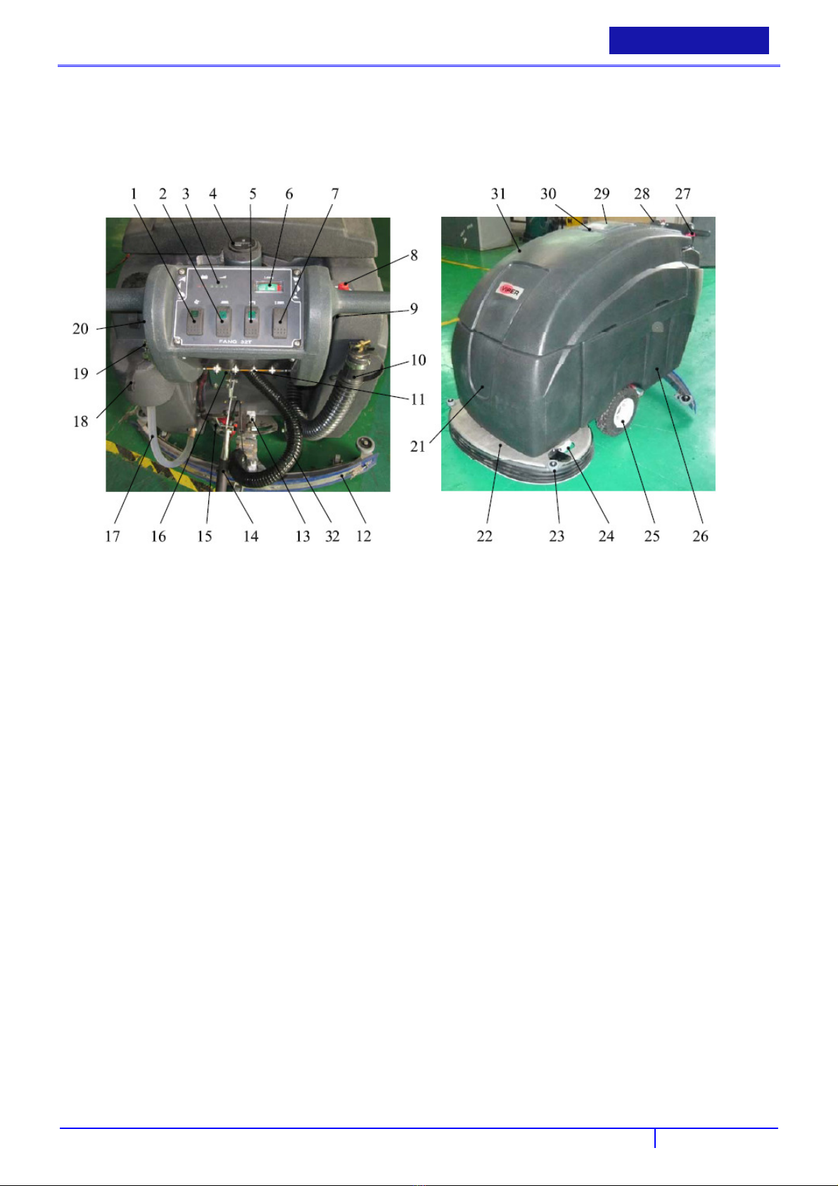
MACHINE DESCRIPTION
MACHINE STRUCTURE
USER MANUAL
ENGLISH
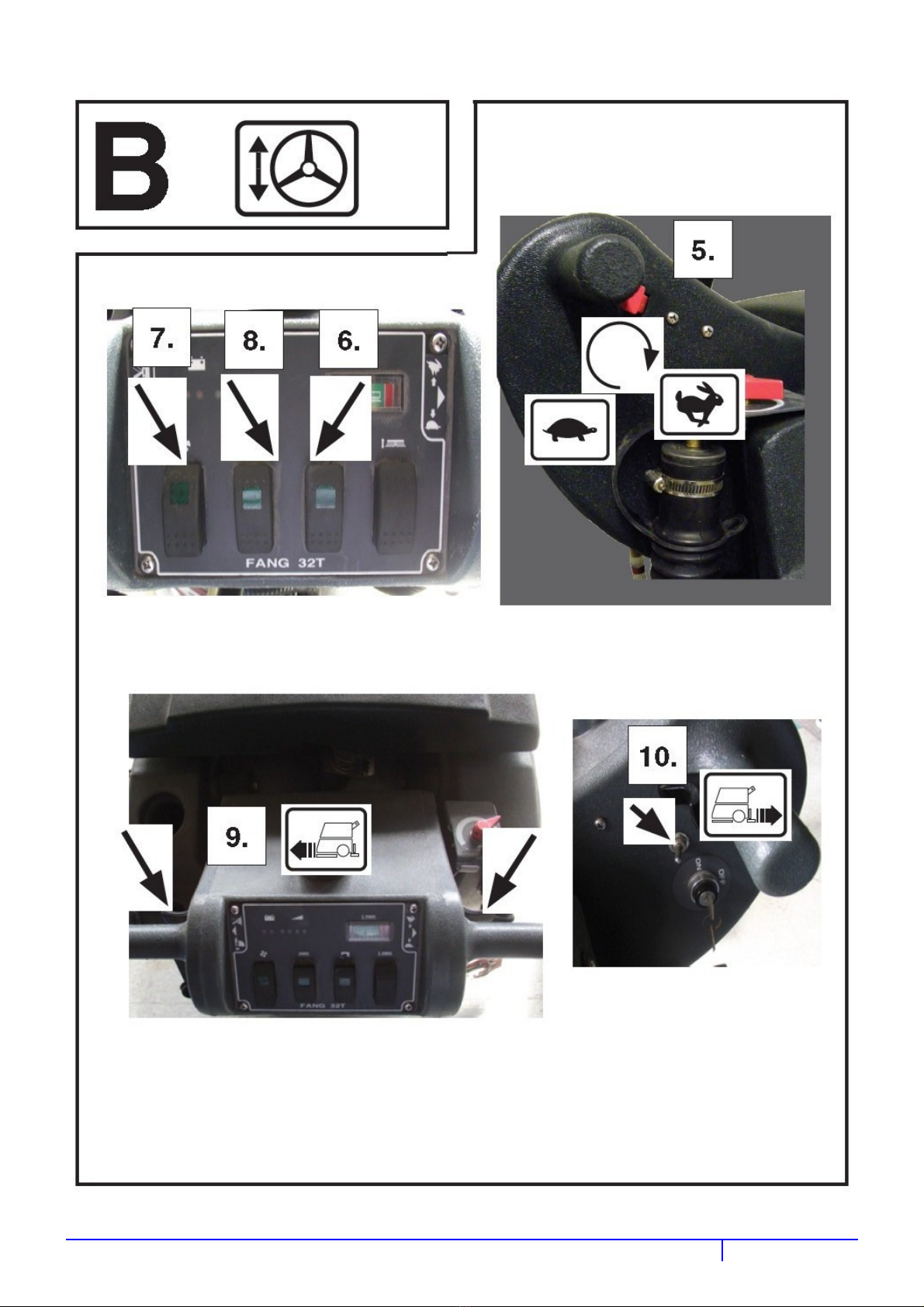
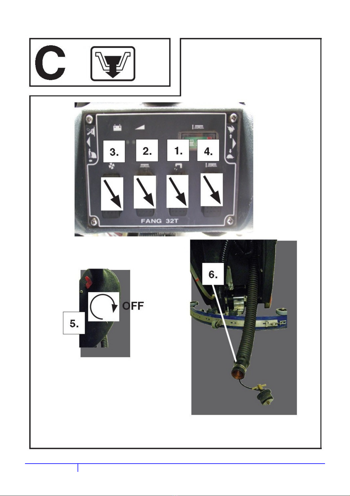
1. Vacuum ON/OFF switch
2. Brush ON/OFF switch
3. Battery level meter
4. Hour meter
5. Solution ON/OFF switch
6. Brush pressure meter
7. Brush pressure UP/DOWN switch
8. Solution control knob
9. Speed control knob
10. Recovery tank drain hose
11. Circuit breakers
12. Squeegee assembly
13. Squeegee adjustment nut & shaft
14. Squeegee lift lever
15. Rear casters
16. Console adjustment levers
17. Solution tank level sight tube
18. Rear solution fill
19. Key switch
20. Reverse switch
21.Front cover
22. Scrub head
23. Protective rollers
24. Scrub head door
25. Transport wheels
26. Solution tank
27. Operating triggers
28. Control housing
29. Recovery tank lid
26. Solution filter assembly
31. Recovery tank
32. Squeegee vacuum hose
13
Page 16

ENGLISH
BETRİEBSANLEİTUNG
ACCESSORIES/OPTIONS
In addition to the standard components, the machine can be equipped with the following accessories/options, according to the
ma-chine specific use:
Brush
Pad driver
For further information concerning the optional accessories, contact an authorised retailer.
TECHNICAL DATA
Model
Machine height
Solution/clean water tank capacity
Recovery water tank capacity
Rear wheel diameter
Vacuum system motor power
Drive system motor power
Drive speed (variable)
Gradeability
Sound pressure level at workstation
Standard batteries
Vacuum system circuit capacity
Cleaning width
Squeegee width
Machine maximum length
mm
l
l
mm
W
W
km/h
%
dB(A)
Ah @ 20 h
mm H2O
mm
mm
mm
FANG 32T-EU
(1 brush/pad-holder, with drive system)
1090
115
106
297
650
370
0 - 4.5
2
70
6-6V/305AmP.hR
1,860
800
1020
1690
Machine width without squeegee
Brush diameter
Weight without batteries and with empty tanks
Gross W
Brush motor power
Brush speed
eight
Battery compartment size (length x width x
height)
Charger output voltage
mm
mm
kg
kg
W
rpm
mm
V
1050
2*406
200
286
740
200
580*500*370
36
14
Page 17
USER MANUAL
ENGLISH
BATTERY CAPACITY LIGHTS
(16AWG GRN)
8
(16AWG WHT)
5
(14AWG RED)
13
(14AWG BLK)
01
(14AWG BLK)
16
(14AWG RED)
15
(16AWG BLU)
18
(16AWG BLU)
17
(16AWG WHT)
1
(12AWG RED)
12
(16AWG BLU)
0
(12AWG RED)
10
(12AWG RED)
10
12
(12AWG RED)
(14AWG RED)
14
(14AWG RED)
20
6V BATTERY
_
6V BATTERY
_
6V BATTERY
+
+
+
_
HOUR
METER
1
CIRCUIT BREAKER
VACUUM
SOLENOID
6V BATTERY
_
6V BATTERY
_
6V BATTERY
+
0
-
+
22
KEY
SWITCH
(16AWG WHT)
12A
BRUSH
SOLENOID
12
AMMETER
0
0
21
23
0
20
VACCUM MOTOR
CIRCUIT BREAKER
+
+
_
19
35A
(4AWG RED)
(4AWG BLK)
0
VACUUM
SWITCH
TRIGGER SWITCH
5
(16AWG WHT)
3
DRIVING MOTOR
SPEED
CONTROLLER
3
22
7
0
35A
LEFT BRUSH
CIRCUIT BREAKER
(16AWG BLU)
(16AWG BLU)
(16AWG WHT)
19
(14AWG RED)
+
0
21
5
RITHT BRUSH CIRCUIT BREAKER
(16AWG BLU)
0
(16AWG BLU)
0
(16AWG BLU)
0
11
BRUSH
SWITCH
5
B+ B- M2
12 11
(12AWG RED)
11
(4AWG RED)
_+_
(4AWG BLK)
0
0
7
6
6
19
M1
35A
11 (12AWG RED)
5
B+
0
B -
9 (14AWG RED)
1 (16AWG WHT)
+
10 (12AWG RED)
10 (12AWG RED)
14 (14AWG RED)
0 (16AWG BLU)
_
01 (14AWG BLK)
02 (16AWG GRN)
03 (12AWG BLK)
03 (12AWG BLK)
04 (14AWG BLK)
0 (16AWG BLU)
PCB
00
8
6
SOLUTION
SWITCH
F
R
DIRECTION
SWITCH
4.7K
2W
5
5
0
ACTUATOR
8 (16AWG GRN) 2 (16AWG GRN)
17 (16AWG BLU)
12 (12AWG RED)
12 (12AWG RED)
20 (14AWG RED)
15 (14AWG RED)
5 (16AWG WHT)
0 (16AWG BLU)
13 (14AWG RED)
17
UP
18
DOWN
SOLUTION SOLENOID
18 (16AWG BLU)
ACTUATOR MOTOR
03 (12AWG BLK)
LEFT BRUSH MOTOR
03 (12AWG BLK)
RIGHT BRUSH MOTOR
04 (14AWG BLK)
VACUUM MOTOR
16 (14AWG BLK)
DRIVE MOTOR
3
0
9
MAIN
SOLENOID
15
Page 18

ENGLISH
BETRİEBSANLEİTUNG
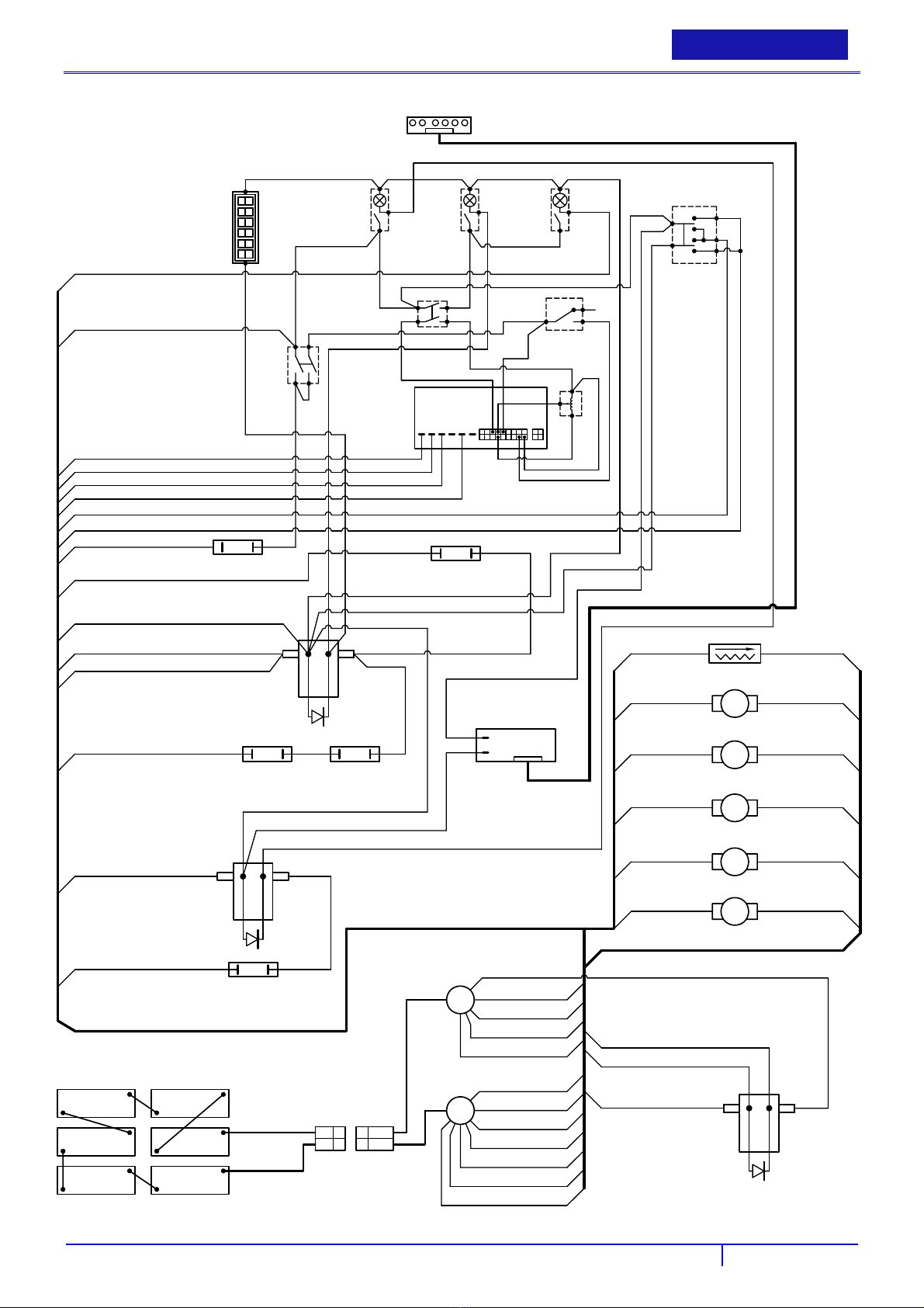
WIRING DIAGRAM (FANG32T-EU )
WIRING DIAGRAM(FANG32T-EU)
Colour codes
BLK Black
BLU Blue
GRU Green
RED Red
WHT White
1 BATTERY CAPACITY LIGHTS insert translation
2 HOUR METER
3 VACUUM SWITCH
4 BRUSH SWITCH
5 SOLUTION SWITCH
6 AMMETER
7 ACTUATOR
8 TRIGGER SWITCH
9
10 DIRECTION SWITCH
11
12 KEY SWITCH
13 CIRCUIT BREAKER
14 BRUSH SOLENOID
15 PCB
16 SOLUTION SOLENOID
DRIVING MOTOR SPEED
RIGHT BRUSH CIRCUIT
insert translation
insert translation
insert translation
insert translation
insert translation
insert translation
insert translation
insert translation
insert translation
insert translation
insert translation
insert translation
insert translation
İnsert translation
İnsert translation
17 ACTUATOR MOTOR
18 LEFT BRUSH MOTOR
19 VACUUM MOTOR
20 DRIVE MOTOR
21 VACUUM SOLENOID
22 VACUUM CIRCUIT BREAKER
23 MAIN SOLENIOD
24 RIGHT BRUSH MOTOR
5
2
6
1
ATTERY
B
insert translation
insert translation
insert translation
insert translation
insert translation
insert translation
insert translation
insert translation
nsert translation
i
Page 19
USER MANUAL
ENGLISH
OPERATION
BEFORE STARTING THE MACHINE
WARNING!
On some points of the machine there are some adhesive plates indicating:
DANGER
WARNING
CAUTION
CONSULTATION
While reading this Manual, the operator must pay careful attention to the symbols shown on the plates. Do not cover these
plates for any reason and immediately replace them if damaged.
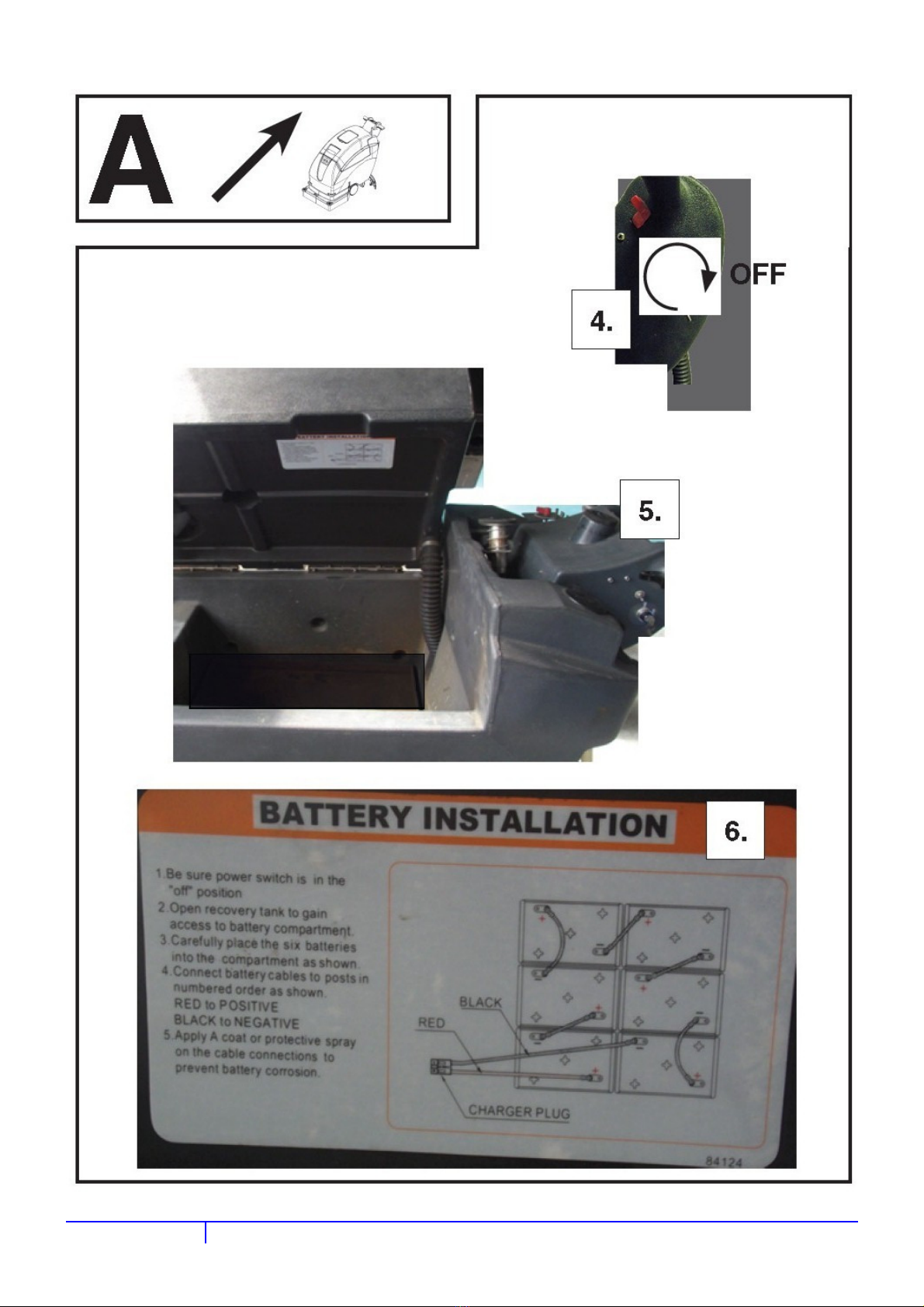
BATTERY INSTALLATION
WARNING!
The electric components of the machine can be seriously damaged if the batteries are either improperly
installed or connected. The batteries must be installed by qualified personnel only.
Set the function electronic board and the battery charger (optional) according to the type of batteries used
(WET or GEL).
Check the batteries for damage before installation.
Disconnect the battery connector and the battery charger plug.
Handle the batteries with great care.
Install the battery terminal protection caps supplied with the machine.
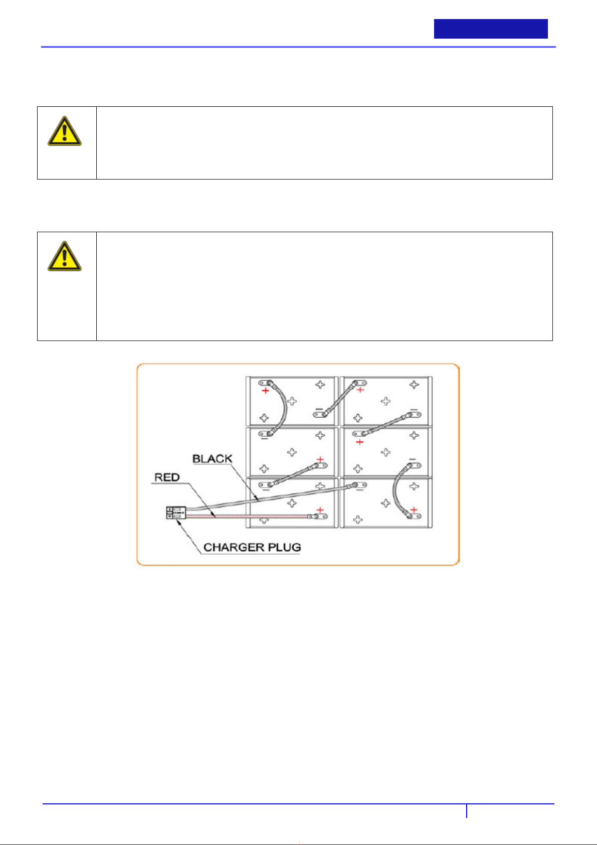
The machine requires two 12 V batteries, connected according to the below diagram:
There are no batteries on the machine from factory, but customers can purchase batteries ( WET or GEL).
Buy appropriate batteries (see Technical Data paragraph).
For battery choice and installation, apply to qualified battery dealers.
Set the machine and the battery charger according to the type of batteries installed (WET or GEL) as shown in the
following para-grap
a) When batteries (WET or GEL) are already installed and ready to be used
Check that the batteries are connected to the machine with the charger plug.
Insert the ignition key (19) and turn it to “on”.
If the green warning light (3) turns on, the batteries are ready to be used.
If the yellow or red warning light (3) turns on, the batteri es must be charged (see the procedure in Maintenance
chapter).
b) When batteries (WET) are installed on the machine, but without electrolyte
Open the cover (29) and check that the recovery water tank (31) is empty, otherwise empty it with the drain hose (10).
17
Page 20
ENGLISH
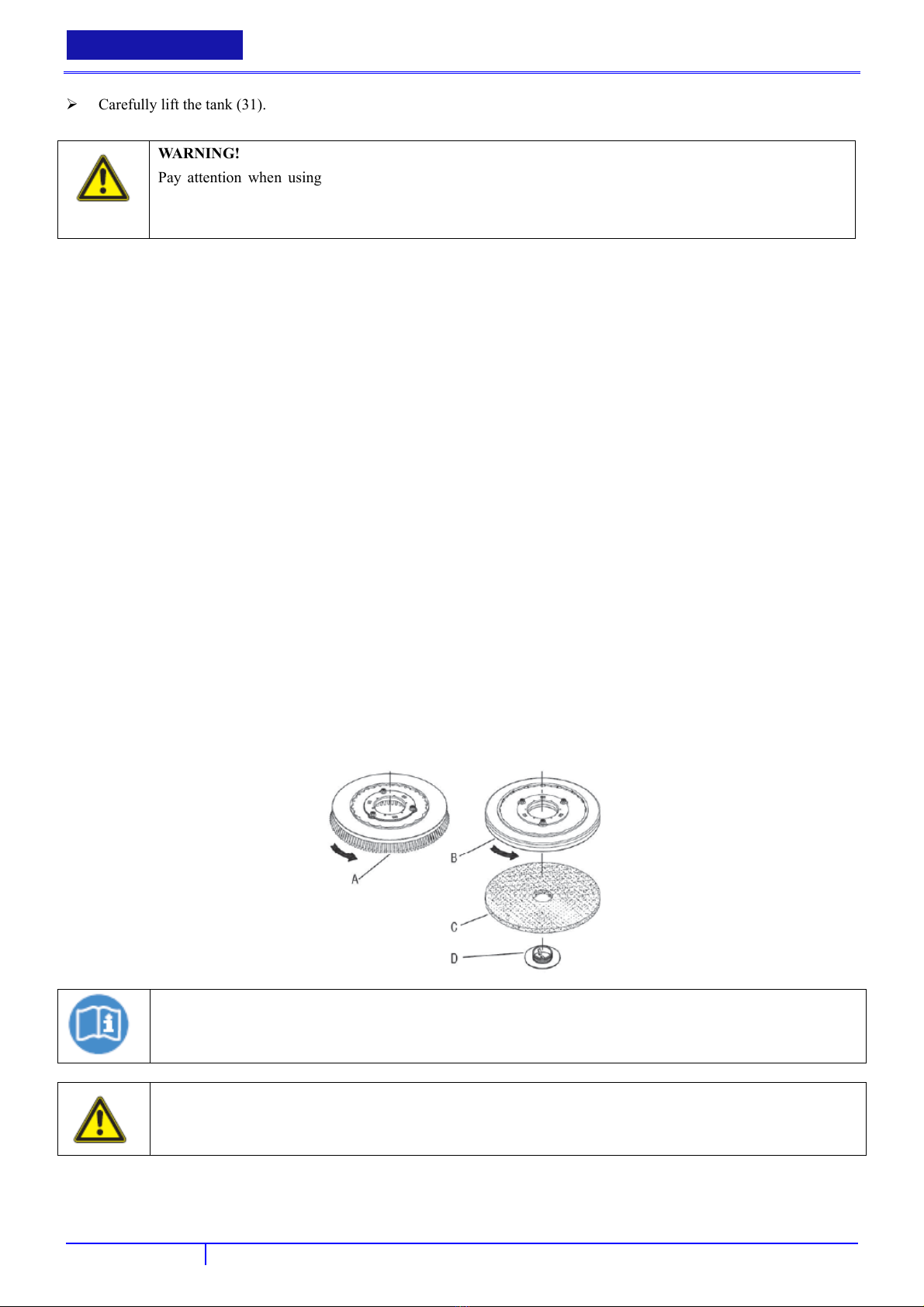
Carefully lift the tank (31).
WARNING!
Pay attention when using sulphuric acid, as it is corrosive. If it comes in contact with skin or eyes, rinse
thoroughly with water and consult a physician.
Batteries have to be filled in a well-ventilated area. Wear protective gloves.
Fill up the battery cells with sulphuric acid for batteries (density 1.27 to 1.29 kg at 25°C) in accordance with the
instructions shown in the Battery Manual. The correct quantity of sulphuric acid is shown in the Battery Manual.
To avoid damaging the floor, dry with a cloth both acid and water on the top of the batteries after charging.
Let the batteries rest and fill in with sulphuric acid in accordance with the instructions shown in the Battery Manual.
Charge the batteries (see the procedure in Maintenance chapter).
BETRİEBSANLEİTUNG
BATTERY CHARGER SETTING
The charger default setting is common position for AGM,Gel,SLA,VRLA from factory
If needed use WET position only for lead batteries. Please contact dealer.
PRE-OPERATION CHECKS
Sweep the outside of the machine.
Make sure the voltage of machine conforms to local voltage.
Check that squeegee is properly installed.
Check that brush / pad is properly installed.
INSTALLING PAD DRIVER OR BRUSH
Ensure that the machine is turned off.
Lower brush head assembly to the floor by stepping on the foot pedal and pushing pedal forward.
Tilt the machine backward to access the drive motor hub.
NOTE
Remove the squeegee assembly prior to tilting the machine backwards. It makes the process faster and easier.
WARNING!
Do not keep the machine tilted back for a long time. This could cause battery acid to leak from the batteries.
If using a pad driver, first attach the appropriate pad to the pad driver surface.
Mount the pad driver or brush to the drive motor hub by lining up the three studs with the three holes in the drive motor
hub. Once in the holes, rotate the driver toward the spring clip to lock driver into place.
18
Page 21
USER MANUAL
ENGLISH
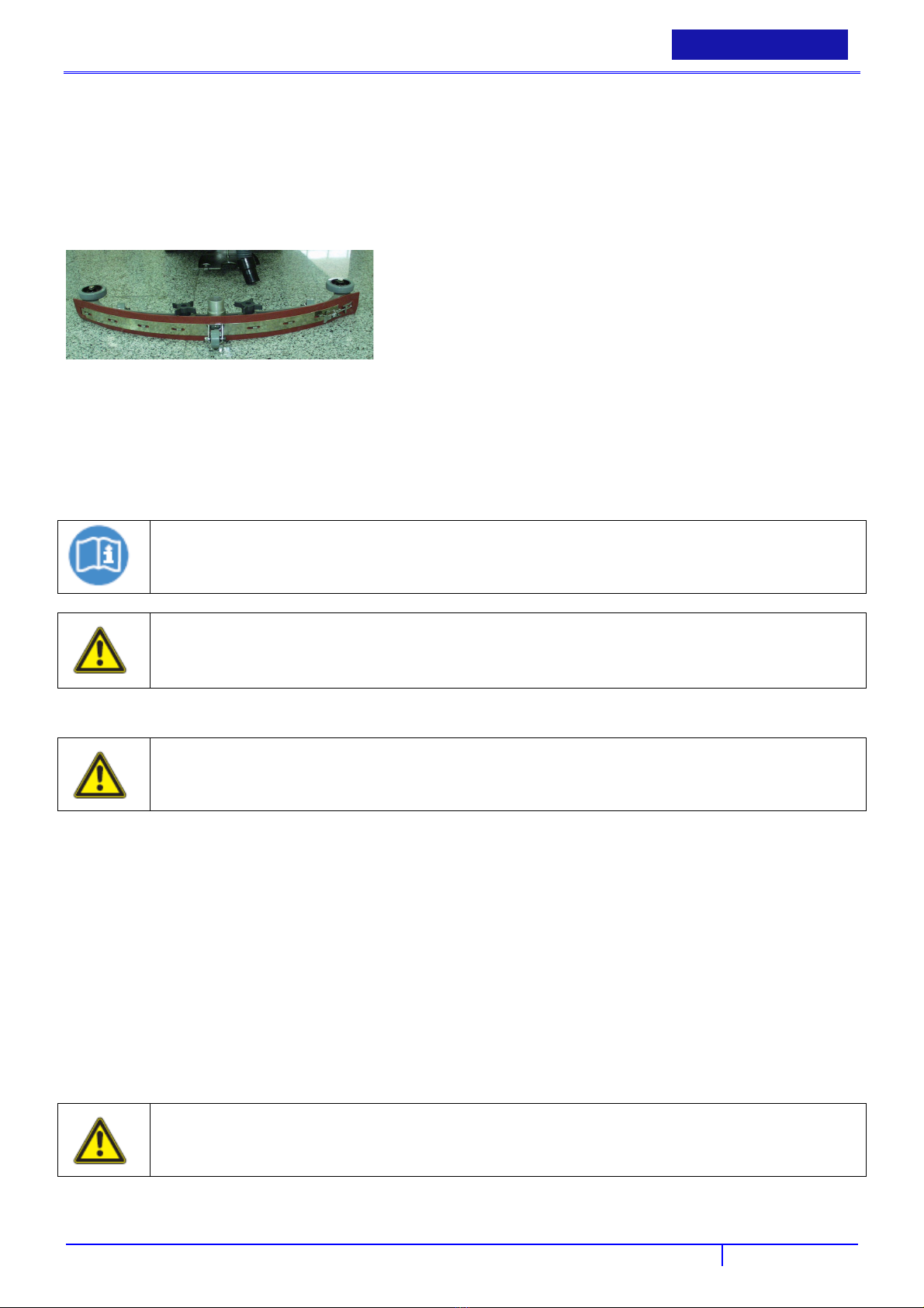
MOUNTING THE SQUEEGEE
Pull back on the squeegee lift lever to raise the squeegee bracket up.
Loosen the two knobs on the squeegee and slide the squeegee into the slots at the rear of the squeegee bracket. (the
wheels on the squeegee point to the back)
Tighten the knobs securely.
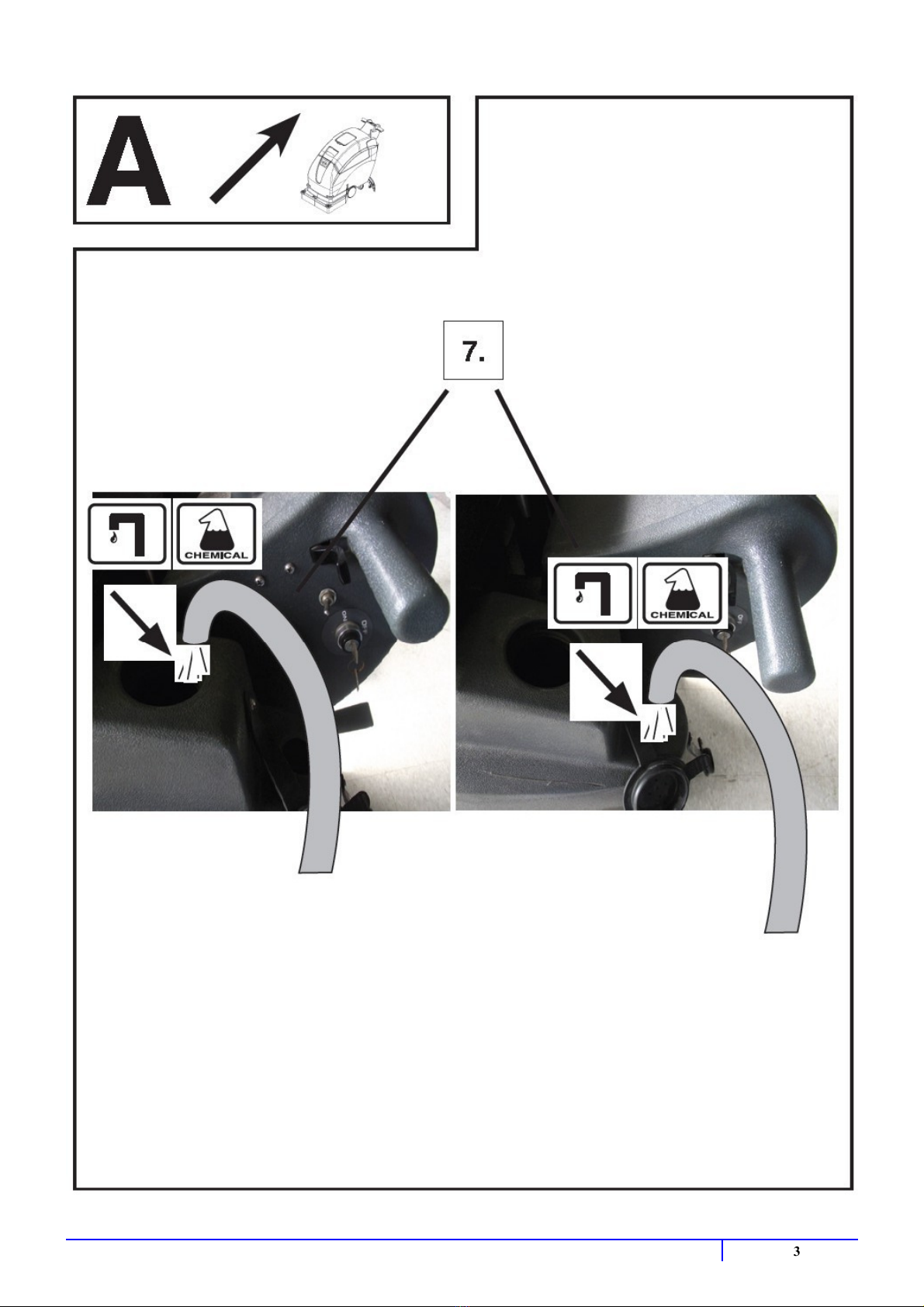
FILLING THE SOLUTION TANK
The Fang 32T-EU can be filled in two different locations:
a. Front fill area for use with a hose or a bucket.
b. Rear fill area for use with a hose only.
Determine which fill area you would like to use to fill the machine with water.
Fill solution tank with up to 52 liters of water. (water temperature should not exceed 40° C). The clear tube in the back
left of the machine has gallon markers to help determine the water level in the solution tank.
NOTE
If you are filling the solution tank with a bucket, make sure the bucket is clean. This will prevent debris from
clogging the lines or solenoid.
WARNING!
Do not put any flammable materials into solution tank. This can cause an explosion or a fire. Only use
recommended cleaning chemicals. Contact your janitorial supply distributor for recommendations on proper
chemicals.
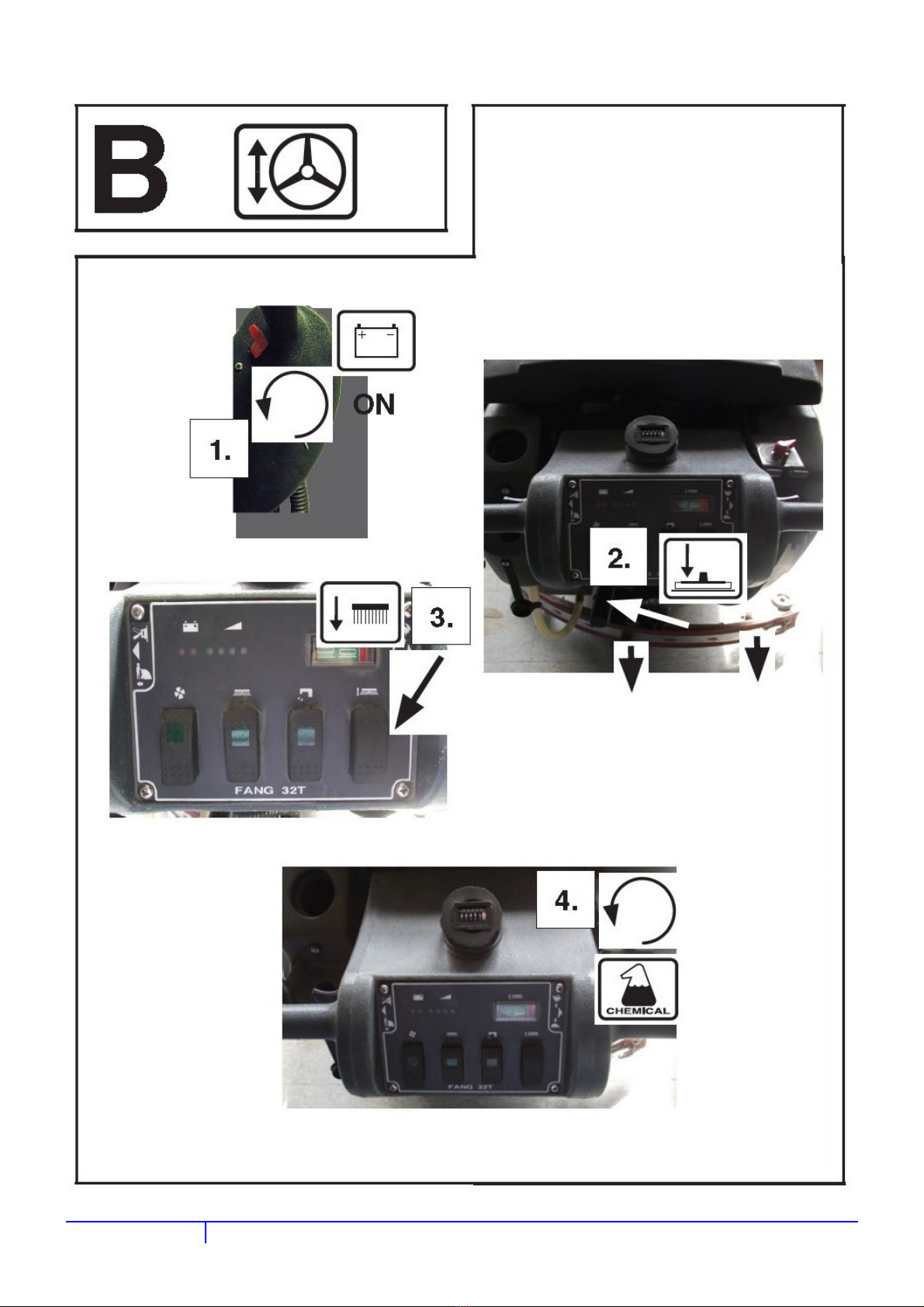
MACHINE START AND STOP
WA
RNING!
Do not operate machine unless you have read and understand this manual.
Set control housing to a comfortable operating height by squeezing together the two thumb levers (16) directly
underneath the housing.
Lower squeegee assembly to the floor by releasing the lift lever (14) from its locked position.
Lower brush head assembly to the foor by turn brush pressure switch(7)to ON position.
Turn vacuun motor switch (1) to “ ON” position.
Turn brush motor switch (2) to “ON” position.
Turn the solution switch (5) to “ON” position.
a. Solution will not begin to flow until the operating triggers are pulled.
The Fang 32T-EU is self-propelled. The speed can be controlled by a knob (9) located on the right side of the control
housing.
The Fang 32T-EU has reverse. In order to activate reverse,there is a toggle switch (20) located on the left side of the
control housing.
To begin scrubbing, pull on one or both of the red operating triggers (27). When these triggers are pulled, the brush will
begin to spin and the solution will begin to flow.FANG32T-EU:will propel itself.FANG32T-EU:Begin scrubbing by
moving the machine forward.
WARNING!
Do not keep the machine in the same position with the pad / brush spinning, or you could cause damage to the
floor.
Adjust amount of solution flow by turning the solution control knob (8). Turn to the right for more solution, or turn left
for less solution.
19
Page 22
ENGLISH
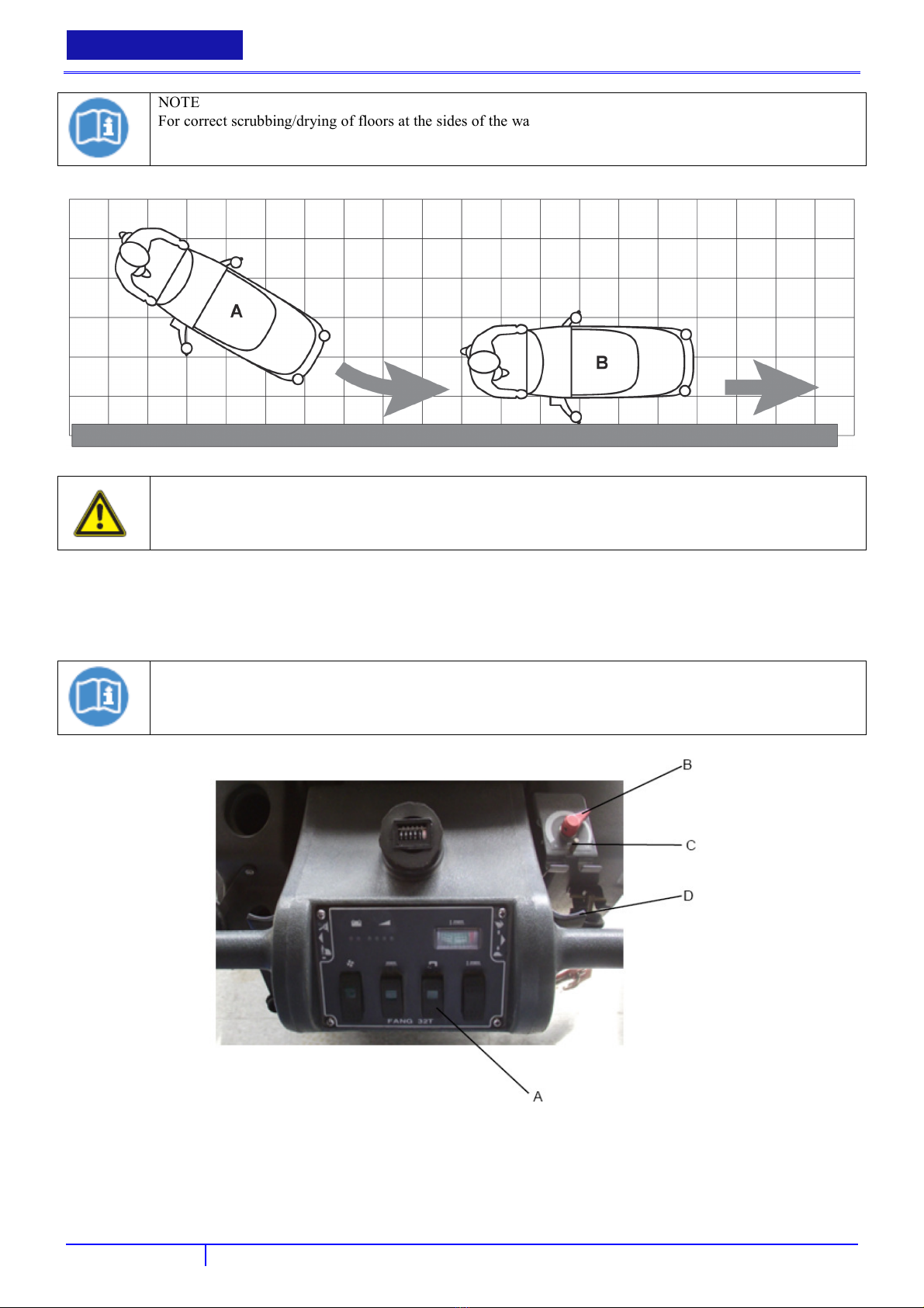
NOTE
For correct scrubbing/drying of floors at the sides of the walls, Viper suggests to go near the walls with the right
side of the machine as shown.
BETRİEBSANLEİTUNG
CAUTION!
To avoid any damage to the floor surface, turn off the brush/pad-holder when the machine stops in one place,
especially when the extra pressure function is on.
SOLUTION FLOW ADJUSTMENT
Turn the solution switch (A) to “ON” position.
Adjust amount of solution flow by turning the solution control knob (B), turn left (counter-clockwise) for more solution,
or Turn right (clockwise) for less solution. The pin (C) is limit position of the solution control knob (B).
NOTE
Even if turn on the solution switch (A) ,the solution will not begin to flow until the operating triggers (D) are
pulled.
BATTERY DISCHARGE DURING OPERATION
Until the green warning light (3) stays on, the batteries allow the machine to work normally.
When the green warning light (3) turns off, and the yellow warning light (3) turns on, it is advisable to charge the batteries,
because the residual autonomy will last for a few minutes (depending on battery characteristics and work to be performed).
20
Page 23
USER MANUAL
When the red warning light (3) turns on, the autonomy is over. After a few seconds, the brush/pad-holder is automatically
tuned off, while the vacuum system and the drive system stay on, to finish drying the floor and drive the machine to the
appointed recharging area.
CAUTION!
Do not use the machine with discharged batteries, to avoid damaging the batteries and reducing the battery life.
ENGLISH
WHILE OPERATING MACHINE
Occasionally look through the clear recovery tank lid to see if there is any foam build-up. If excessive foam is found, add
defoamer to the recovery tank.
WARNING!
Foam must not enter the float shut-off screen, or damage can occur to the vacuum motor. Foam will not activate
the machines float shut-off device.
Occasionally view the clear tube at the back left of the machine to check the amount of cleaning solution that is left in the
machine.
Occasionally check the battery level meter (3). When meter is in the red, recharge the batteries.
WARNING!
When battery meter is in the red, do not continue to operate the machine. Battery damage may result.
If the squeegee assembly leaves streaks on the floor, raise the squeegee off the floor and wipe the blades down with a
damp cloth.
WARNING!
Do not use your fingers to wipe or remove debris from the blades, as injury may occur.
When the solution tank runs empty, turn off the brush switch, solution switch and raise the brush head. Keep the squeegee
down and continue to vacuum until all the dirty water is picked up. (see TANK DRAINING section to learn how to drain
recovery and solution tanks)
NOTE
The brush motor is circuit breaker protected to protect it from damage. If this breaker trips, it can’t be reset
immediately.
You must first determine what caused the circuit breaker to trip, and allow the motor to cool down before you
can reset the circuit breaker.
TANK DRAINING
Turn the power off on the machine.
With the squeegee and brush head in their “up” position, transport machine to approved area for draining tank(s).
DRAINING THE RECOVERY (DIRTY) TANK
NOTE
Any time scrubbing is completed, or when refilling solution tank, the recovery tank should be drained and
cleaned.
WARNING!
If the recovery tank is not drained when the solution tank has been refilled, foam or water may enter the float
shut-off mechanism and cause damage to the vacuum motor.
Remove the drain hose from the holder, and place the drain hose over the floor drain. Twist off the drain hose plug to
begin the draining process. In order to completely empty the recovery tank, hinge opens the recovery tank and let it rest
on the support stand.
Clean the recovery tank after every use. Use a fresh water hose to rinse out the recovery tank. Be careful not to spray
21
Page 24
ENGLISH
BETRİEBSANLEİTUNG
water into the float shut-off mechanism.
NOTE
If you are storing the machine for any period of time, always leave the clear recovery tank lid off the tank so the
tank can dry completely and smell fresh.
Replace the drain hose plug tightly as soon as you are done draining the tank.
DRAINING THE SOLUTION (CLEAN) TANK
NOTE
Any time scrubbing operation is completed, the solution tank should be drained and cleaned.
Pull down on the clear tube (back left of the machine) to remove it from the hose barb. This will allow the solution to
flow freely into a bucket or floor drain.
Rinse the solution tank with clean water after every use. This will help prevent chemical buildup and clogging of the
solution lines.
With clean water in solution tank, turn machine power on, solution switch “on” and pull the operating triggers. This will
allow the clean water to flush through and clean the solution plumbing.
Once tank is rinsed, flushed and drained, reconnect the clear tube to the hose barb. Be sure the tube is pushed all the way
up on the hose barb.
BATTERY CHARGING
NOTE
For the best machine performance, keep batteries charged at all times. Do not let them sit in a discharged
condition.
NOTE
If the machine has an optional battery charger installed, the machine cannot operate if the charger is not on
board. In case of battery charger malfunction, contact an authorised Service Center.
CAUTION!
Use only approved chargers with the following specifications:
Automatic shut off circuit
Deep cycle charging
Output current of 25-35 Amps
Output voltage of 36 Volts
CAUTION!
Batteries are dangerous! Batteries emit hydrogen gas and an explosion or fire can result. Keep sparks and fire
away from batteries at all times. When charging the machine, make sure the battery compartment is left open.
Place charge and machine in a well ventilated area.
Turn machine off.
Open recovery tank up, exposing battery compartment .
Check fluid level in each battery cell. Do not charge batteries unless fluid is slightly covering the battery plates. Do not
overfill the batters. Overfilling may cause the batteries to overflow during charging due to expansion. Replace the caps
prior to charging.
Plug approved charger into grounded wall out let before plugging the charger into the machine.
Plug charger into red charger receptacle located in the front left of the battery compartment.
Flip up the recovery tank “Kick stand” and gently lay the recovery tank down until it rests on the stand.
The battery charger will automatically begin to charge the batteries, and it will automatically shut down once the batteries
are fully charged.
Upon completion of charging, first unplug the charger from the wall outlet, and then disconnect the charger from the
machine.
Check the battery level after charging is complete. If fluid level is low, add distilled water to bring the fluid level up to the
bottom of the sight tubes. Replace the caps and wipe the batteries down with a towel.
2
2
Page 25
USER MANUAL
ENGLISH
MAINTENANCE
To keep the machine performing well for many years, please follow the following maintenance procedures.
CAUTION!
Always confirm that the machine is switched off and the battery cable is disconnected prior to performing any
mainte-nance or repairs
DAILY MAINTENANCE
Remove pad driver / brush and clean with approved cleaner.
Drain recovery and solution tanks completely and rinse out with clean water. Visually check the recovery tank for debris
and clean out as necessary.
Raise squeegee assembly off floor and wipe it down with a damp towel. Be sure to store the squeegee in the up position.
Remove the float shut-off assembly and rinse it out with clean water.
Clean machine with an approved cleaner and a damp towel. Don’t spray water to clean the outside of machine to avoid
damage to motor and wiring.
Recharge batteries.
WEEKLY MAINTENANCE
Check fluid level in batteries.
Check batteries for loose or corroded cables.
Keep battery tops clean from corrosion.
MONTHLY MAINTENANCE
Check machine for leaks and loose fasteners.
Lubricate all grease points and pivot points with silicon spray and approved grease.
Place machine over a floor drain. Flush solution system by pouring 10 liters of hot water and approved alkaline detergent
into the solution tank and running machine (with solution control on) for 45 seconds. Turn machine off and let it sit
overnight. Then next day, drain the remaining solution and rinse the solution tank out with clean water.
VACUUM SYSTEM MOTOR FILTER CLEANING
Drive the machine on a level floor.
Turn the ignition key (19) to “OFF”.
Open the recovery water tank.
If necessary, drain the water from the tank in order to make the filter visible.
Check that the pre-filter is clean. If necessary clean it with water and compressed air, then install it.
Perform steps 1, 2 and 3 in the reverse order.
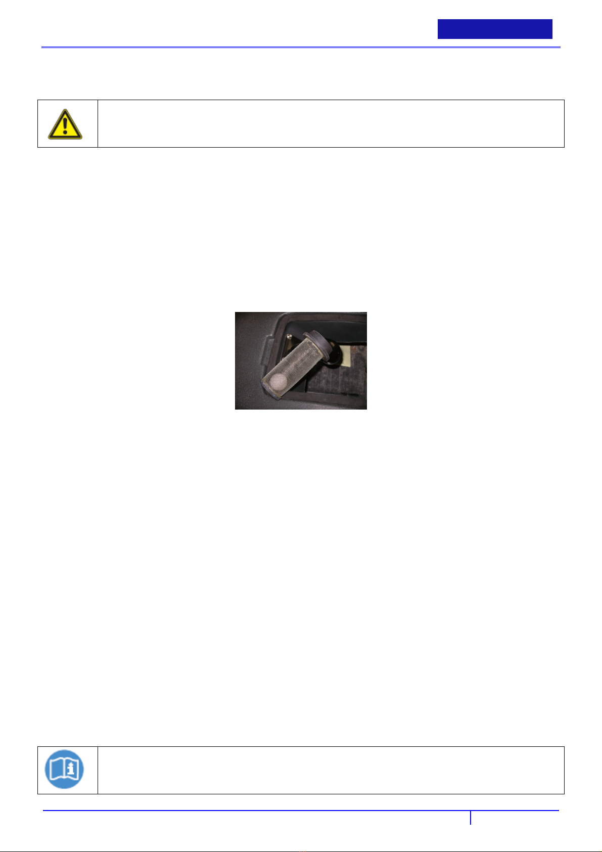
SOLUTION/CLEAN WATER FILTER CLEANING
Drive the machine on a level floor.
Turn the ignition key (19) to “OFF”.
Remove the transparent cover (D) (the water filter position is under the machine), then remove the filter strainer (B).
Clean and install them on the support (A).
NOTE
The filter strainer (B) must be correctly positioned on the housing (E) of the support (A).
23
Page 26
ENGLISH
BETRİEBSANLEİTUNG
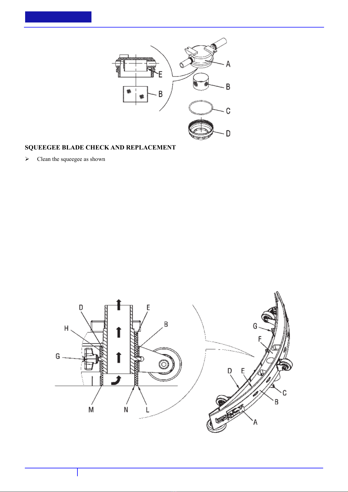
SQUEEGEE BLADE CHECK AND REPLACEMENT
Clean the squeegee as shown in the previous paragraph.
Check that the edge (M) of the front blade (D) and the edge (L) of the rear blade (E) lay down on the same level, along
their length; otherwise adjust their height according to the following procedure:
− Disengage the retainers (A) to adjust the rear blade (E); then engage the retainers.
− Loosen the handwheels (G) and adjust the front blade (D); then tighten the handwheels.
Check the front blade (D) and rear blade (E) for integrity, cuts and tears; if necessary replace them as shown below.
Check that the front corner (N) of the rear blade is not worn; otherwise, overturn the blade to replace the worn corner with
an integral one. If the other corners are worn too, replace the blade according to the following procedure:
− Disengage the retainers (A) and remove the retaining strip (B), then replace/overturn the rear blade (E). Install the
blade in the reverse order of removal.
− Unscrew the handwheels (G) and remove the retaining strip (H), then replace the front blade (D). Install the blade in
the reverse order of removal.
After the blade replacement (or overturning), adjust the height as shown in the previous step.
Connect the vacuum hose (32) to the squeegee.
Install the squeegee (12) and screw down the handwheels (13).
If necessary, adjust the squeegee adjusting handweel(13).
BRUSH/PAD CLEANING
24
Page 27
USER MANUAL
ENGLISH
CAUTION!
Risk of cuts.
It is advisable to wear protective gloves when cleaning the brush/pad because there may be sharp debris.
Remove the brush/pad from the machine, as shown in Use chapter.
Clean and wash the brush/pad with water and detergent.
Check that the brush/pad is integral and not excessively worn; otherwise replace it.
TROBLESHOOTING
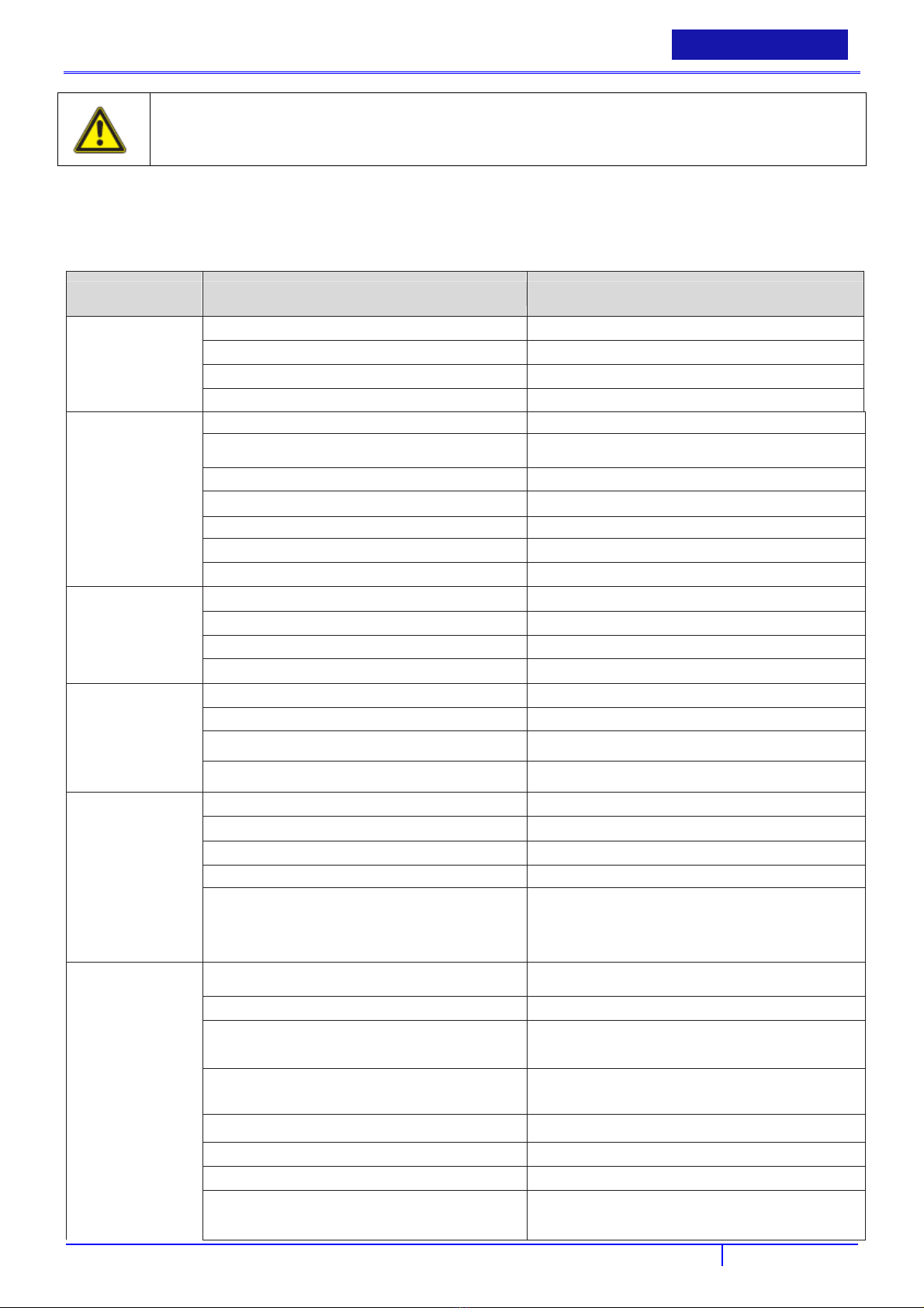
PROBLEM CAUSE SOLUTION
No power Bad batteries Replace batteries
Batteries need to be charged Charge batteries (see Battery Charging)
Loose battery cable Tighten loose cable(s)
Batteries not connected properly Follow battery installation instructions
Brush motor does
not run
Vacuum motor does
not run
Short run time Batteries need to be charged Charge batteries (see Battery Charging)
Bad brush switch Contact Viper Distributor
Brush circuit breaker has tripped Check brush motor for obstructions and reset breaker
Rectifier has burned out Contact Viper Distributor
Bad wiring Contact Viper Distributor
Bad brush motor Contact Viper Distributor
Carbon brushes worn out Contact Viper Distributor
Bad solenoid Contact Viper Distributor
Bad vacuum switch Contact Viper Distributor
Bad wiring Contact Viper Distributor
Bad vacuum motor Contact Viper Distributor
Carbon brushes worn out Contact Viper Distributor
Batteries need maintenance See Battery Maintenance in this manual
Bad cell in battery(s) Replace batteries
Bad charger Replace charger
Little or no solution
flow
Poor water pick up Squeegee clogged Clean debris off squeegee with damp towel
Bad solution switch Contact Viper Distributor
Clogged solution solenoid Contact Viper Distributor
Clogged solution filter Remove filter and clean
Solution line obstructed Remove solution line and clean
Solution flow adjustment knob in need of adjustment Increase flow by twisting solution adjustment knob to
the right. Decrease flow by twisting solution adjustment
knob
Squeegee blades worn Install new squeegee blades
Squeegee not mounted correctly Confirm that the squeegee assembly is securely fastened
to the machine and not loose fitting.
Vacuum hoses have a hole or are loose Check hose connections and make sure they are firm.
Replace hose if damaged.
Vacuum hose may be clogged Check hose for debris and remove any clog.
Drain hose stopper is loose Tighten drain plug.
Batteries need to be charged Charge batteries (see Battery Charging)
Vacuum motor is loose Tighten vac motor mounting screws. Do not over tighten
or damage will occur.
25
Page 28
ENGLISH
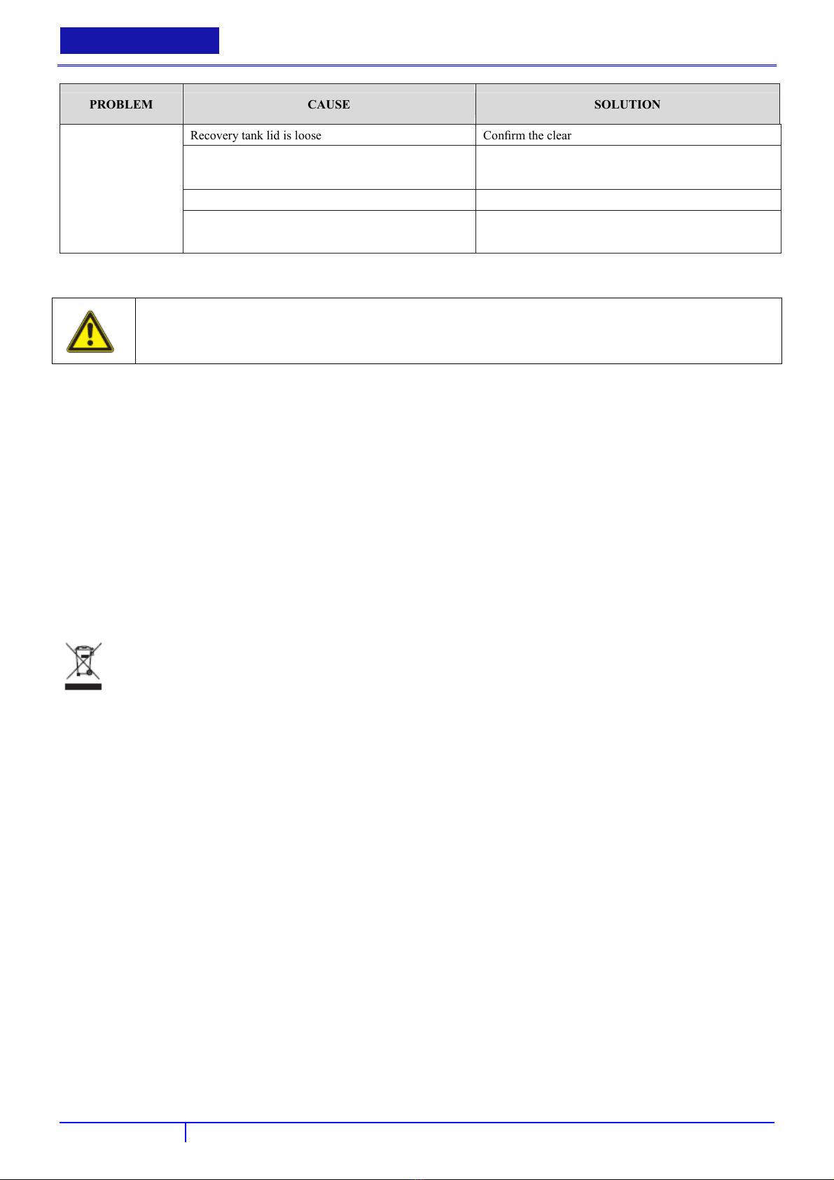
PROBLEM CAUSE SOLUTION
BETRİEBSANLEİTUNG
Recovery tank lid is loose Confirm the clear recovery tank lid is securely in place.
Recovery tank inlet hole is clogged Drain recovery tank and tilt tank on side. Check the inlet
hole for debris and remove debris.
Recovery tank is full Drain recovery tank.
Float shut off is clogged Remove float shut off from inside recovery tank and
remove any debris.
STORAGE
CAUTION!
If you are storing the machine in an area which can freeze, be sure both tanks and the solution plumbing are
empty of all water and dry!
Store the appliance in a dry place, protected from frost.
The machine storage temperature must be between 0°C and +40°C.
Always store the machine indoors.
Always take off the pad driver / brush
Always store the machine with the squeegee assembly raised off the floor.
If storing in an area which may reach freezing temperatures, be sure to drain all fluids from the machine prior to storage.
Any dam-age caused by freezing temperatures will not be covered by the warranty.
Drain the recovery tank and remove the clear on the top of the recovery tank so that it can “breathe” during storage.
Drain the solution tank of all fluid.
RECYCLING THE CLEANER
Make the old cleaner unusable immediately:
Remove batteries
Do not discard of electrical appliances with household waste.
As specified in European Directive 2002/96/EC on old electrical and electronic appliances, used electrical goods
must be collected separately and recycled ecologically. Contact your local authorities or your nearest dealer for
further information.
26
Page 29

BETRİEBSANLEİTUNG
DEUTSCH
INHALTSVERZEİCHNİS
EINLEITUNG ............................................................................................................................................................................. 28
ZWECK UND INHALT DES HANDBUCHS……………………………………………………………………………28
ZIEL………………………………………………………………………………………………………………………28
WIE DIESES HANDBUCH AUFBEWAHRT WIRD……………………………………………………………………28
KONFORMITÄTSERKLÄRUNG……………………………………………………………………………………28
KENNZEICHNUNGSDATEN……………………………………………………………………………………………28
ANDERE REFERENZ-HANDBÜCHER…………………………………………………………………………………28
ERSATZTEILE UND WARTUNG……………………………………………………………… ………………28
ÄNDERUNGEN UND VERBESSERUNGEN……………………………………………………………………………29
VORGESEHENER VERWENDUNGSZWECK…………………………………………………………………………29
KONVENTIONEN………………………………………………………………………………………………………29
ENTPACKEN/LIEFERUNG ..................................................................................................................................................... 29
SICHERHEIT ............................................................................................................................................................................. 29
SYMBOLE ZUR KENNZEICHNUNG VON ANWEISUNGEN………………………………………………………30
ALLGEMEINE ANLEITUNG……………………………………………………………………………………………30
MASCHINENBESCHREIBUNG .............................................................................................................................................. 34
MASCHINENAUFBAU…………………………………………………………………………………………………34
ZUBEHÖR/OPTIONEN…………………………………………………………………………………………………35
SCHALTPLAN (FANG32T-EU)…………………………………………………………………………………………37
BETRIEB ..................................................................................................................................................................................... 38
VOR DEM STARTEN DER MASCHINE………………………………………………………………………………38
WÄHEND DES MASCHINENBETRIEBS………………………………………………………………………………42
WARTUNG ................................................................................................................................................................................. 44
TÄGLICHE INSTANDHALTUNG………………………………………………………………………………………44
WÖCHENTLICHE INSTANDHALTUNG………………………………………………………………………………45
MONATLICHE INSTANDHALTUNG…………………………………………………………………………………45
REINIGUNG DES MOTORFILTERS DES VAKUUMSYSTEMS………………………………………………………45
LÖSUNGS-/FRISCHWASSER-FILTERREINIGUNG…………………………………………………………………45
ÜBERPRÜFUNG UND AUSTAUSCH DES GUMMIABZIEHERWISCHERS………………………………………45
BÜRSTEN-/PAD-REINIGUNG…………………………………………………………………………………………46
PROBLEMBEHEBUNG ............................................................................................................................................................ 46
LAGERUNG ................................................................................................................................................................................ 47
RECYCLING DER REINIGUNGSMASCHINE ..................................................................................................................... 48
27
Page 30

DEUTSCH
BETRİEBSANLEİTUNG
EINLEITUNG
HINWEIS
Die Zahlen in Klammern beziehen sich auf die Komponenten im Kapitel Maschinenbeschreibung.
ZWECK UND INHALT DES HANDBUCHS
Dieses Handbuch möchte dem Bediener alle nötigen Informationen zum ordnungsgemäßen, sicheren und autonomen Gebrauch
der Maschine bieten. Es enthält Informationen zu technischen Daten, Sicherheit, Betrieb, Lagerung, Wartung, Ersatzteilen und
Entsorgung. Bevor die Maschine eingesetzt wird, müssen Bediener und qualifizierte Techniker dieses Handbuch sorgfältig
durchlesen. Wenden Sie sich in Zweifelsfragen bezüglich der Interpretation der Anleitung oder weiterführenden Informationen
an Viper.
ZIEL
Dieses Handbuch ist für Bediener vorgesehen sowie für Techniker , die Wartungsarbeiten an der Maschine durchführen
dürfen.
Bediener dürfen Verfahren, die qualifizierten Technikern vorbehalten sind, nicht ausführen. Viper übernimmt für Schäden
aufgrund der Nichtbeachtung dieses Verbots keine Verantwortung.
WIE DIESES HANDBUCH AUFBEWAHRT WIRD
Diese Betriebsanleitung muss in einem angemessen Behälter, geschützt vor Flüssigkeiten und anderen Substanzen, die sie
beschädigen könnten, in der Nähe der Maschine aufbewahrt werden.
KONFORMITÄTSERKLÄRUNG
Die dieser Maschine beigelegte Konformitätserklärung bestätigt die Konformität der Maschine mit den geltenden Gesetzen.
HINWEIS
Zwei Kopien der Original-Konformitätserklärung sind den Maschinenunterlagen beigefügt.
Die CE-Erklärung ist in der Kurzanleitung enthalten.
KENNZEICHNUNGSDATEN
Modell- und Seriennummer der Maschine befinden sich auf dem Typenschild.
Diese Informationen sind für die Ersatzteilbestellung nützlich. Verwenden Sie die folgende Tabelle, um die
Kennzeichnungsdaten der Maschine festzuhalten.
MASCHINEN-Modell ...............................................................................
MASCHINEN-Seriennummer ...................................................................
ANDERE REFERENZ-HANDBÜCHER
-
Wartungshandbuch (kann vom Viper-Kundencenter bezogen werden)
-
Ersatzteilliste (siehe www.vipercleaning.eu)
ERSATZTEILE UND WARTUNG
lle notwendigen Betriebs-, Wartungs- und Reparaturverfahren müssen von qualifiziertem Personal oder dem
A
Viper-Kundencenter durchgeführt werden. Nur Original-Ersatzteile und -Zubehör dürfen verwendet werden. Wenden Sie sich
für die Wartung oder Ersatzteil- sowie Zubehörbestellung an Viper und geben Sie die Modell- und Seriennummer der
Maschine an.
8
2
Page 31

USER MANUAL
DEUTSCH
ÄNDERUNGEN UND VERBESSERUNGEN
Viper verbessert seine Produkte kontinuierlich und behält sich das Recht vor, nach eigenem Ermessen Änderungen und
Verbesserungen vorzunehmen, ohne dazu verpflichtet zu sein, diese Vorteile an früher verkaufte Maschinen anzubringen.
Jede Änderung und/oder Beifügung von Zubehör muss von Viper zugelassen und durchgeführt werden.
VORGESEHENER VERWENDUNGSZWECK
Alle automatischen Reinigungsmaschinen sind ausschließlich für die Feuchtreinigung wasserresistenter Bodenbeläge in
Gebäude-Innenbereichen bestimmt. Automatische Reinigungsmaschinen können für verlegte Teppiche und zur
Teppichreinigung nicht verwendet werden.
Dieses Gerät ist für den kommerziellen Gebrauch geeignet, zum Beispiel in Hotels, Schulen, Krankenhäusern, Fabriken,
Geschäften, Büros und Vermietungsunternehmen.
Eine andere Verwendung wird als unsachgemäße Verwendung angesehen. Der Hersteller übernimmt für jeglichen Schaden aus
solch einer Verwendung keinerlei Haftung. Die Risiken aus einer solchen Verwendung liegen ausschließlich beim Benutzer.
Die ordnungsgemäße Verwendung schließt ebenfalls die sachgemäße Bedienung, Wartung, Reparatur ein, wie sie vom
Hersteller spezifiziert wird.
Vom Benutzer selbst durchgeführte Änderungen an der automatischen Maschine schließen die Haftung des Herstellers für
daraus resultierende Schäden aus.
Bödenbelege müssen vor Gebrauch der Maschine auf Angemessenheit für diese Reinigungsmethode überprüft werden.
Beachten sie die Flächenpressung im Fall von punktelastischen Böden wie z. B. in Sporthallen!
Der Hersteller übernimmt keine Verantwortung für Schäden an der Maschine oder an zu reinigenden Bodenbelägen, die aus der
falschen Verwendung von Bürsten und Reinigungsmitteln entstehen.
KONVENTIONEN
Vorwärts, rückwärts, vor, hinter, links, rechts und nach oben beziehen sich auf die Position des Bedieners, d. h. die
Arbeitsposition.
ENTPACKEN/LIEFERUNG
Folgen Sie zum Entpacken der Maschine genau der Anleitung auf der Verpackung.
Überprüfen Sie bei Lieferung der Maschine, ob Verpackung sowie Maschine während des Transports nicht beschädigt wurden.
Bewahren Sie die Verpackung im Falle sichtbarer Schäden auf, damit sie vom Lieferanten überprüft werden kann.
den Lieferanten sofort an, um Schadensansprüche anzumelden.
Überprüfen Sie den Packungsinhalt, um sicherzustellen, dass folgende Teile vorhanden sind:
-
Maschine
-
Gummischieber-Baugruppe
-
Bürstenantrieb (und Padtriebteller)
Rufen Sie
SICHERHEIT
Folgende Symbole weisen auf potenziell gefährliche Situationen hin. Diese Informationen immer sorgfältig durchlesen und alle
notwendigen Sicherheitsvorkehrungen zum Schutz von Personen und Eigentum treffen.
Die Kooperation des Bedieners ist für die Vermeidung von Verletzungen unerlässlich. Kein Unfallvermeidungsprogramm kann
ohne die vollkommene Kooperation der für den Maschinenbetrieb verantwortlichen Person wirken.
Die meisten Unfälle in Fabriken, die während des Arbeitens und Umhergehens entstehen, werden durch das Nicht-Beachten der
29
Page 32

DEUTSCH
einfachsten Regeln bezüglich der Rücksichtnahme verursacht.
Ein vorsichtiger und rücksichtsvoller Bediener stellt die beste Garantie gegen Unfälle dar und ist für ein erfolgreiches
Präventionsprogramm unerlässlich.
BETRİEBSANLEİTUNG
SYMBOLE ZUR KENNZEICHNUNG VON ANWEISUNGEN
GEFAHR!
Eine Gefahr, die unmittelbar zu ernsten und irreversiblen Verletzungen oder sogar zum Tod führen kann.
WARNUNG!
Eine Gefahr, die zu ernsten Verletzungen oder sogar zum Tod führen kann.
VORSICHT!
Eine Gefahr, die zu minderschweren Verletzungen und Schäden führen kann.
HINWEIS
Hinweis auf eine Anmerkung im Zusammenhang mit wichtigen und nützlichen Funktionen.
ALLGEMEINE ANLEITUNG
Spezifische Warnungen und Vorsichtsmaßnahmen, die über potenzielle Gefährdungen von Personen und der Maschine
informieren, werden untenstehend angeführt.
Die Maschine darf
-
nur von Personen verwendet werden, die über den korrekte Verwendung instruiert und ausdrücklich mit dem Betrieb
beauftragt wurden
-
nur unter Aufsicht betrieben werden
-
nicht von Kindern verwendet werden.
Der Arbeitsplatz befindet sich hinter der Reinigungsmaschine.
Unsichere Arbeitstechniken dürfen nicht angewandt werden.
Führen Sie die Reinigungsmaschine immer mit beiden Händen am Griff.
Steht die Reinigungsmaschine, die Bürsteneinheit sofort ausschalten, um Schäden am Bodenbelag zu vermeiden.
In folgenden Situationen wird die Maschine ausgeschaltet und der Batteriestecker gezogen:
-
vor der Reinigung und Wartung
-
vor dem Austausch von Komponenten
-
bevor an der Maschine Veränderungen vorgenommen werden
Die Verwendung der Reinigungsmaschine unterliegt den aktuellen nationalen Bestimmungen. Neben den Betriebshinweisen
und verbindlichen, im Einsatzland geltenden Bestimmungen zur Unfallverhütung müssen die anerkannten Regeln in Sachen
Sicherheit und fachgerechtem Arbeiten beachtet werden.
TRANSPORT
Wird die Reinigungsmaschine in Aufzügen transportiert, müssen aktuelle Sicherheitsbestimmungen, insbesondere im Hinblick
auf die Lastenkapazität, beachtet werden.
30
Page 33

USER MANUAL
DEUTSCH
BETRIEB
Um den unbefugten Gebrauch der Maschine zu verhindern, muss die Stromversorgung ausgeschaltet oder gesperrt werden,
indem beispielsweise der Schlüssel des Netzschalters abgezogen wird.
Treffen Sie alle notwendigen Vorsichtsmaßnahmen, damit sich Haare, Schmuck oder lose Kleidung nicht in den beweglichen
Maschinenteilen verfangen.
Schließen Sie vor dem Gebrauch der Maschine alle Türen und/oder Abdeckungen.
Die Betriebstemperatur der Maschine muss zwischen 0 °C und +40 °C liegen.
Die Luftfeuchtigkeit muss zwischen 30 % und 95 % liegen.
Die Maschine darf nicht als Transportmittel verwendet werden.
Verwenden Sie im Brandfall einen Pulver- und keinen Wasser-Feuerlöscher.
Manipulieren Sie nicht die Schutzvorkehrungen der Maschine und beachten Sie gewissenhaft die einfache Wartungsanleitung.
Kein Gegenstand darf durch die Öffnungen dringen. Bei verstopften Öffnungen darf die Maschine nicht verwendet werden.
Halten Sie die Öffnungen immer frei von Staub, Haaren und anderen, den Luftstrom reduzierenden Fremdkörpern.
Die auf der Maschine angebrachten Schilder dürfen nicht entfernt oder modifiziert werden.
Wenn die Maschine in Übereinstimmung mit der Anleitung verwendet wird, geht von den Vibrationen keine Gefahr aus. Das
Vibrationsniveau der Maschine liegt unter 2,5 ms² (98/37/EEC-EN 1033/1995).
Die Hand-/Armvibrationsniveaus liegen deutlich unter 2,5 m/s² (gemessen nach ISO 5349), dem Grenzwert für einen
kontinuierlichen Arbeitszeitraum von 8 Stunden.
Die Maschine darf auf Verkehrswegen und öffentlichen Straßen nicht verwendet werden.
Viper-Maschinen können zusammen mit Standard-Reinigungsmitteln, die keine Viper-Maschinenteile beschädigen (keine
Lösungsmittel oder andere aggressive Flüssigkeiten), verwendet werden. Viper wird für keine Schadenfälle im Hinblick auf
die Verwendung aggressiver Reinigungsmittel in Viper-Maschinen aufkommen. Wenn Sie ein spezielles Reinigungsmittel
benötigen, wenden Sie sich bitte an Ihren Viper-Händler.
Passen Sie beim Transport der Maschine auf, wenn die Temperatur unter dem Gefrierpunkt liegt. Das Wasser im Tank oder in
den Schläuchen könnte gefrieren und die Maschine ernsthaft beschädigen.
WARTUNG
Um den ordnungsgemäßen und sicheren Betrieb der Maschine zu gewährleisten, muss die regelmäßige Wartung, wie im
jeweiligen Kapitel dieses Handbuchs gezeigt, von autorisiertem Personal oder vom Viper-Kundencenter durchgeführt werden.
Vor der Durchführung von Wartungs- oder Reparaturarbeiten müssen alle Anweisungen sorgfältig durchgelesen werden.
Arbeiten Sie nicht unter der aufgebockten Maschine ohne die Anbringung von Sicherheitsständern.
Die Maschine darf nicht direkt bzw. unter Verwendung von Hochdruck-Wasserdüsen oder mit korrosiven Substanzen gereinigt
werden.
GARANTIE
Bezüglich der Garantie gelten die allgemeinen Geschäftsbedingungen.
Nicht genehmigte Modifizierungen der Maschine, die Verwendung falscher Bürsten und Reinigungsmittel sowie die
Verwendung der Maschine für einen anderen als den vorgesehenen Verwendungszweck entbindet den Hersteller von jeglicher
Haftung für daraus resultierende Schäden.
31
Page 34

DEUTSCH
BETRİEBSANLEİTUNG
PRÜFUNGEN UND ZULASSUNGEN
Elektrische Prüfungen müssen in Übereinstimmung mit den Bestimmungen der Sicherheitsvorschriften (BGV A3) und der
DIN VDE 0701 Teil 1 und Teil 3 durchgeführt werden. In Übereinstimmung mit der DIN VDE 0702 müssen diese Prüfungen
in regelmäßigen Abständen und nach Reparaturen oder Modifikationen durchgeführt werden.
ELEKTRISCHE KOMPONENTEN
GEFAHR
Batterien.
Explosionsgefahr.
Das Aufladen von Batterien erzeugt hochexplosiven Wasserstoff. Belassen Sie die Tankbaugruppe
während des Aufladens der Batterien offen und führen Sie diesen Vorgang in gut belüfteten Bereichen
und fern von offenen Flammen durch.
Lassen Sie die an die Stromversorgung angeschlossene Maschine zur Verringerung der Brand-,
Stromschlag- und Verletzungsgefahr nicht unbeaufsichtigt.
Trennen Sie vor jeglichen Wartungsarbeiten das Batterieladekabel von der Stromversorgung.
Nicht rauchen, während die Batterien aufgeladen werden.
Die Verwendung von nicht originalen Ersatzteilen, Zubehörteilen, Batterien und Ladegeräten kann die
Sicherheit der Maschine beeinträchtigen. Verwenden Sie nur Ersatzteile und Zubehörteile von Viper
sowie Batterien, die VIPER empfohlen hat.
Wenn Sie nicht genehmigte und nicht empfohlene Batterien und Ladegeräte verwenden, kommt VIPER
nicht für dadurch entstehende Kosten von Schäden (Gewährleistung) auf.
VORSICHT
Batterieladegerät.
Stromschlag durch defekte Netzanschlussleitung oder defektes Ladekabel.
Das Berühren einer defekten Netzanschlussleitung oder eines defekten Ladekabels kann zu ernsten und sogar
tödlichen Verletzungen führen.
Halten Sie die Batterie fern von Funken, Flammen und glühenden Materialien. Während des normalen
Betriebs werden explosive Gase freigesetzt.
Stellen Sie vor der Verwendung des Batterieladegeräts sicher, dass die auf dem Seriennummernschild der
Maschine abgebrachten Frequenz- und Spannungswerte der elektrischen Netzspannung entsprechen.
Beschädigen Sie nicht die Netzstromleitung (z. B. durch Überfahren, Zerren oder Quetschen).
Überprüfen Sie in regelmäßigen Abständen, ob die Stromleitung beschädigt ist oder Anzeichen von
Verschleiß aufweist.
Lassen Sie die defekte Netzanschlussleitung von Ihrem Viper-Kundendienstrepräsentanten oder einem
qualifizierten Elektriker vor der nächsten Verwendung der Maschine austauschen.
Die Maschine darf nicht am Batterieladekabel gezogen oder getragen werden und das Batterieladekabel
darf keinesfalls als Griff genutzt werden.
Schließen Sie eine Tür nicht über dem Batterieladekabel und ziehen Sie das Batterieladekabel nicht um
scharfe Kanten oder Ecken.
Halten Sie das Batterieladekabel fern von heißen Oberflächen.
Die Batterien dürfen bei beschädigtem Batterieladekabel oder Stecker nicht aufgeladen werden.
Funktioniert die Maschine nicht ordungsgemäß, wurde sie beschädigt, im Freien stehen gelassen oder in
Wasser fallen gelassen, muss sie zum Kundendienstcenter überstellt werden.
TREPPEN UND STEIGUNGEN
VORSICHT
Kipp- und Rutschgefahr auf Treppen und Steigungen.
Wenn Treppen und Steigungen behandelt werden, besteht die Gefahr von Personen- und Sachschäden.
Behandeln Sie keine Treppen.
Verwenden Sie die Maschine nur auf ebenen Flächen mit einer maximalen Steigung von 2 %.
BODENBELÄGE
VORSICHT
Schäden an empfindlichen Bodenbelägen.
Besonders empfindliche Bodenbeläge können durch die Reinigung beschädigt werden.
Bevor Sie die Reinigungsmaschine verwenden, überprüfen Sie bitte, ob sich die Bodenbeläge für dieses
Reinigungstechnik eignen.
Beachten Sie die Flächenpressung auf punktelastischen Böden, z. b. in Sporthallen!
Verwenden Sie nur von Viper zugelassene Reinigungsmittel.
GESUNDHEITSSCHÄDLICHE STOFFE
32
Page 35

WARNUNG
Gesundheitsschädliche Stoffe in Bodenbelägen.
Bodenbeläge können gesundheitsschädlige Stoffe enthalten, die während der Reinigung herausgelöst werden.
Reinigen Sie keine Bodenbeläge, aus denen sich gesundheitsschädliche Stäube oder Flüssigkeiten herauslösen
können.
EXPLOSIONSGEFAHR
WARNUNG
Brennbare und explosive Stoffe.
Explosionsgefahr in explosionsfähiger Atmosphäre oder Bereichen, in denen brennbare und explosive Stoffe
gelagert werden.
Betreiben Sie die Maschine nicht in der Nähe von gefährlichen, brennbaren und/oder explosiven Pulvern,
Flüssigkeiten und Dämpfen.
ERSATZTEILE UND ZUBEHÖR
VORSICHT
Nicht originale Komponenten und ungeeignete Reinigungsmittel.
Die Verwendung von nicht originalen Teilen und ungeeigneten Reinigungsmitteln kann die Sicherheit der
Maschine beeinträchtigen und zu Schäden führen.
Verwenden Sie Ersatzteile und Zubehör von Viper.
Verwenden Sie nur Zubehör und Reinigungsmittel, die mit der Maschine geliefert wurden und solche,
die in der Betriebsanleitung ausgewiesen sind.
USER MANUAL
DEUTSCH
33
Page 36

DEUTSCH
BETRİEBSANLEİTUNG
MASCHINENBESCHREIBUNG
MASCHINENAUFBAU
1.Vakuumnetzschalter (AN/AUS)
2.Bürstennetzschalter (AN/AUS)
3.Batterieanzeige
4.Betriebsstundenzähler
5.Lösungsnetzschalter (AN/AUS)
6.Bürstendruckanzeige
7.Bürstendruckschalter (AUF/AB)
8.Lösungsregelknopf
9.Geschwindigkeitsregelknopf
10.Schmutzwassertank-Ablaufschlauch
11.Leistungsschalter
12.Gummiabzieherbaugruppe
13.Gummiabzieher-Einstellmutter- und -Welle
14.Gummiabzieher-Hubhebel
15.Hintere Rollen
16.Konsolen-Einstellhebel
17.Lösungstank-Füllstandsichtrohr
18.Hintere Lösungs-Befülleinheit
19.Hauptschalter
20.Rückwärts-Schalter
21.Vordere Abdeckung
22.Schrubberkopf
23.Schutzrollen
24.Schrubberkopfklappe
25.Transporträder
26.Lösungsräder
27.Betriebsauslöser
28.Steuergehäuse
29.Schmutzwassertankdeckel
30.Lösungsfilterbaugruppe
31.Schmutzwassertank
32.Gummiabzieher-Vakuumschlauch
34
Page 37

USER MANUAL
DEUTSCH
ZUBEHÖR/OPTIONEN
Neben den Standardkomponenten kann die Maschine mit folgenden maschinenspezifischen Zubehörteilen/Optionen
ausgestattet werden:
● Bürste
● Padtriebteller
Wenden Sie sich für weiter Informationen über optionales Zubehör an einen autorisierten Händler.
TECHNISCHE DATEN
Modell FANG 32T-EU
Bürsten-/Pad-Halter, mit Antriebssystem)
Maschinenhöhe
Lösungs-/Wassertankkapazität
Schmutzwassertankkapazität
Hinterraddurchmesser
Vakuumsystem-Motorleistung
Antriebssystem-Motorleistung
Antriebsgeschwindigkeit (variabel)
Steigfähigkeit
Schalldruckpegel am Arbeitsplatz
Standardbatterien
Vakuumsystem-Stromkreiskapazität
Reinigungsbreite
Gummiabzieherbreite
Maximallänge der Maschine
Maschinenbreite ohne Gummiabzieher
Bürstendurchmesser
Gewicht ohne Batterien und bei leeren Tanks
Gesamtgewicht
Bürstenmotorleistung
Bürstengeschwindigkeit
Batteriefachgröße (Länge x Breite x Höhe)
mm 1090
l 115
l 106
mm 297
W 650
W 370
km/h 0 – 4.5
% 2
dB(A) 70
Ah @ 20 h 6-6V/305AmP.hR
mm H2O 1,860
mm 800
mm 1020
mm 1690
mm 1050
mm 2*406
kg 200
kg 286
W 740
rpm 200
mm 580*500*370
35
Page 38

DEUTSCH
BETRİEBSANLEİTUNG
BATTERY CAPACITY LIGHTS
(16AWG GRN)
8
(16AWG WHT)
5
(14AWG RED)
13
(14AWG BLK)
01
(14AWG BLK)
16
(14AWG RED)
15
(16AWG BLU)
18
(16AWG BLU)
17
(16AWG WHT)
1
(12AWG RED)
12
(16AWG BLU)
0
(12AWG RED)
10
(12AWG RED)
10
12
(12AWG RED)
(14AWG RED)
14
(14AWG RED)
20
6V BATTERY
_
6V BATTERY
_
6V BATTERY
+
+
+
_
HOUR
METER
1
CIRCUIT BREAKER
VACUUM
SOLENOID
6V BATTERY
_
6V BATTERY
_
6V BATTERY
+
0
-
+
22
KEY
SWITCH
(16AWG WHT)
12A
BRUSH
SOLENOID
12
AMMETER
0
0
21
23
0
20
VACCUM MOTOR
CIRCUIT BREAKER
+
+
_
19
35A
(4AWG RED)
(4AWG BLK)
0
VACUUM
SWITCH
TRIGGER SWITCH
5
(16AWG WHT)
3
DRIVING MOTOR
SPEED
CONTROLLER
3
0
0
0
22
7
0
35A
LEFT BRUSH
CIRCUIT BREAKER
(16AWG BLU)
(16AWG BLU)
(16AWG WHT)
19
(14AWG RED)
+
0
21
5
BRUSH
SWITCH
5
B+ B- M2
12 11
RITHT BRUSH CIRCUIT BREAKER
(16AWG BLU)
(16AWG BLU)
(16AWG BLU)
11
(12AWG RED)
11
(4AWG RED)
_+_
(4AWG BLK)
0
0
7
6
6
19
M1
35A
11 (12AWG RED)
5
B+
0
B -
9 (14AWG RED)
1 (16AWG WHT)
+
10 (12AWG RED)
10 (12AWG RED)
14 (14AWG RED)
0 (16AWG BLU)
_
01 (14AWG BLK)
02 (16AWG GRN)
03 (12AWG BLK)
03 (12AWG BLK)
04 (14AWG BLK)
0 (16AWG BLU)
PCB
00
8
6
SOLUTION
SWITCH
F
R
DIRECTION
SWITCH
4.7K
2W
5
5
0
ACTUATOR
8 (16AWG GRN) 2 (16AWG GRN)
17 (16AWG BLU)
12 (12AWG RED)
12 (12AWG RED)
20 (14AWG RED)
15 (14AWG RED)
5 (16AWG WHT)
0 (16AWG BLU)
13 (14AWG RED)
17
UP
18
DOWN
SOLUTION SOLENOID
18 (16AWG BLU)
ACTUATOR MOTOR
03 (12AWG BLK)
LEFT BRUSH MOTOR
03 (12AWG BLK)
RIGHT BRUSH MOTOR
04 (14AWG BLK)
VACUUM MOTOR
16 (14AWG BLK)
DRIVE MOTOR
3
0
9
MAIN
SOLENOID
36
Page 39

SCHALTPLAN (FANG32T-EU)
SCHALTPLAN (FANG32T-EU)
Farbcodes
BLK SCHWARZ
BLU BLAU
GRU GRÜN
RED ROT
WHT WEISS
1 BATTERY CAPACITY LIGHTS BATTERIEKAPAZITÄTSLEUCHTEN
2 HOUR METER BETRIEBSSTUNDENZÄHLER
3 VACUUM SWITCH VAKUUMSCHALTER
4 BRUSH SWITCH BÜRSTENSCHALTER
USER MANUAL
DEUTSCH
5 SOLUTION SWITCH LÖSUNGSSCHALTER
6 AMMETER AMPEREMETER
7 ACTUATOR STELLGLIED
8 TRIGGER SWITCH AUSLÖSERSCHALTER
9 DRIVING MOTOR SPEED CONTROLLER
10 DIRECTION SWITCH RICHTUNGSSCHALTER
11 RIGHT BRUSH CIRCUIT BREAKER RECHTE BÜRSTE LEISTUNGSSCHALTER
12 KEY SWITCH HAUPTSCHALTER
13 CIRCUIT BREAKER LEISTUNGSSCHALTER
14 BRUSH SOLENOID BÜRSTENMAGNETVENTIL
15 PCB PCB
16 SOLUTION SOLENOID LÖSUNGSMAGNETVENTIL
17 ACTUATOR MOTOR STELLGLIEDMOTOR
18 LEFT BRUSH MOTOR LINKER BÜRSTENMOTOR
19 VACUUM MOTOR VAKUUMMOTOR
ANTRIEBSMOTOR-GESCHWINDIGKEITSREGLER
20 DRIVE MOTOR ANTRIEBSMOTOR
21 VACUUM SOLENOID VAKUUMMAGNETVENTIL
22 VACUUM CIRCUIT BREAKER VAKUUMLEISTUNGSSCHALTER
23 MAIN SOLENIOD HAUPTMAGNETVENTIL
24 RIGHT BRUSH MOTOR RECHTER BÜRSTENMOTOR
25 BATTERY BATTERIE
37
Page 40

DEUTSCH
BETRİEBSANLEİTUNG
BETRIEB
VOR DEM STARTEN DER MASCHINE
WARNUNG!
An manchen Stellen der Maschine sind einige Aufkleber angebracht, die Folgendes anzeigen:
GEFAHR
WARNUNG
VORSICHT
RÜCKSPRACHE
Während des Lesens dieses Handbuchs muss der Bediener den Symbolen auf diesen Aufklebern sorgfältige Beachtung schenken.
Diese Aufkleber dürfen keinesfalls bedeckt werden und müssen bei Beschädigung umgehend ausgetauscht werden.
EINSETZEN DER BATTERIE
WARNUNG!
Die elektrischen Komponenten der Maschine können ernsthaft beschädigt werden, wenn die Batterien
entweder nicht richtig eingesetzt oder nicht richtig angeschlossen werden.
Die Batterien dürfen nur von qualifizierten Personen eingesetzt werden.
Stellen Sie die Funktionsplatine und das Batterieladegerät (optional) auf den verwendeten Batterietyp ein
(NASS oder GEL).
Überprüfen Sie die Batterien vor dem Einsetzen auf Beschädigungen.
Trennen Sie den Batteriestecker und den Stecker des Batterieladegerätes ab.
Behandlen Sie die Batterien mit äußerster Vorsicht.
Installieren Sie die Schutzkappen der Batterieklemmen, die mit der Maschine geliefert wurden.
Die Maschine erfordert zwei 12-V-Batterien, die in Übereinstimmung mit dem unteren Diagramm angeschlossen werden:
Ab Werk sind für diese Maschine keine Batterien vorgesehen, doch der Kunde kann Batterien (NASS oder GEL) kaufen.
Kaufen Sie geeignete Batterien (siehe Abschnitt Technische Daten).
Wenden Sie sich für die Wahl und Installation von Batterien an qualifizierte Batteriehändler.
Stellen Sie Maschine und Batterieladegerät auf den Typ der eingesetzten Batterien (NASS oder GEL), wie im folgenden
Abschnitt ausgeführt, ein.
a) Wenn bereits Batterien (NASS oder GEL) eingesetzt wurden und nun betriebsbereit sind,
überprüfen, ob die Batterien an die Maschine und den Ladestecker angeschlossen sind.
den Zündschlüssel (19) einführen und “an”-schalten.
Wenn die grüne Warnanzeige (3) leuchtet, sind die Batterien betriebsbereit.
38
Page 41

USER MANUAL
Leuchtet die gelbe oder rote Warnanzeige (3), müssen die Batterien aufgeladen werden (siehe Verfahren im Kapitel
Wartung).
b) Wenn Batterien (NASS) in die Maschine eingesetzt wurden, jedoch kein Elektrolyt enthalten,
die Abdeckung (29) öffnen und überprüfen, ob der Schmutzwassertank (31) leer ist; diesen ansonsten über das
Ablaufschlauch (10) entleeren.
den Tank vorsichtig anheben (31).
WARNUNG!
Vorsicht walten lassen, wenn Schwefelsäure verwendet wird, da diese korrosiv ist. Falls es zu Haut- oder
Augenkontakt kommt, gründlich mit Wasser spülen und einen Arzt konsultieren.
Batterien müssen in einem gut belüfteten Bereich gefüllt werden. Schutzhandschuhe tragen.
Füllen Sie die Batteriezellen mit Schwefelsäure für Batterien (Dichte 1,27 bis 1,29 kg bei 25 °C) in Übereinstimmung mit
den Anweisungen im Batteriehandbuch. Die korrekte Schwefelsäuremenge ist im Batteriehandbuch angegeben.
Trocknen Sie zur Vermeidung von Schäden am Boden sowohl Säure als auch Wasser auf den Batterien nach dem
Aufladen mit einem trockenen Tuch ab.
Die Batterien ruhen lassen und in Übereinstimmung mit den Anweisungen im Batteriehandbuch mit Schwefelsäure
füllen.
Die Batterien laden (siehe das Verfahren im Abschnitt Wartung).
DEUTSCH
BATTERIELADEEINSTELLUNG
Die ab Werk voreingestellte Ladeeinstellung ist die übliche Position AGM, Gel, SLA, VRLA.
Wenn nötig, die Position NASS nur für Bleibatterien verwenden. Erkundigen Sie sich bei einem Händler.
ÜBERPRÜFUNGEN VOR DEM BETRIEB
Das Maschinenäußere abwischen.
Vergewissern Sie sich, dass die Maschinenspannung der örtlichen Spannung entspricht.
Vergewissern Sie sich, dass der Gummiabzieher ordnungsgemäß installiert ist.
Vergewissern Sie sich, dass Bürste/Pad ordnungsgemäß installiert sind.
PADTRIEBTELLER ODER BÜRSTE INSTALLIEREN
Sicherstellen, dass die Maschine ausgeschaltet ist.
Senken Sie die Bürstenkopfbaugruppe auf den Boden ab, indem Sie auf das Fußpedal treten und das Pedal nach vorne
drücken.
Kippen Sie die Maschine nach hinten, um die Antriebsmotornabe freizulegen.
HINWEIS
Nehmen Sie die Gummiabzieherbaugruppe ab, bevor Sie die Maschine nach hinten kippen. Dies macht den
Vorgang schneller und leichter.
39
Page 42
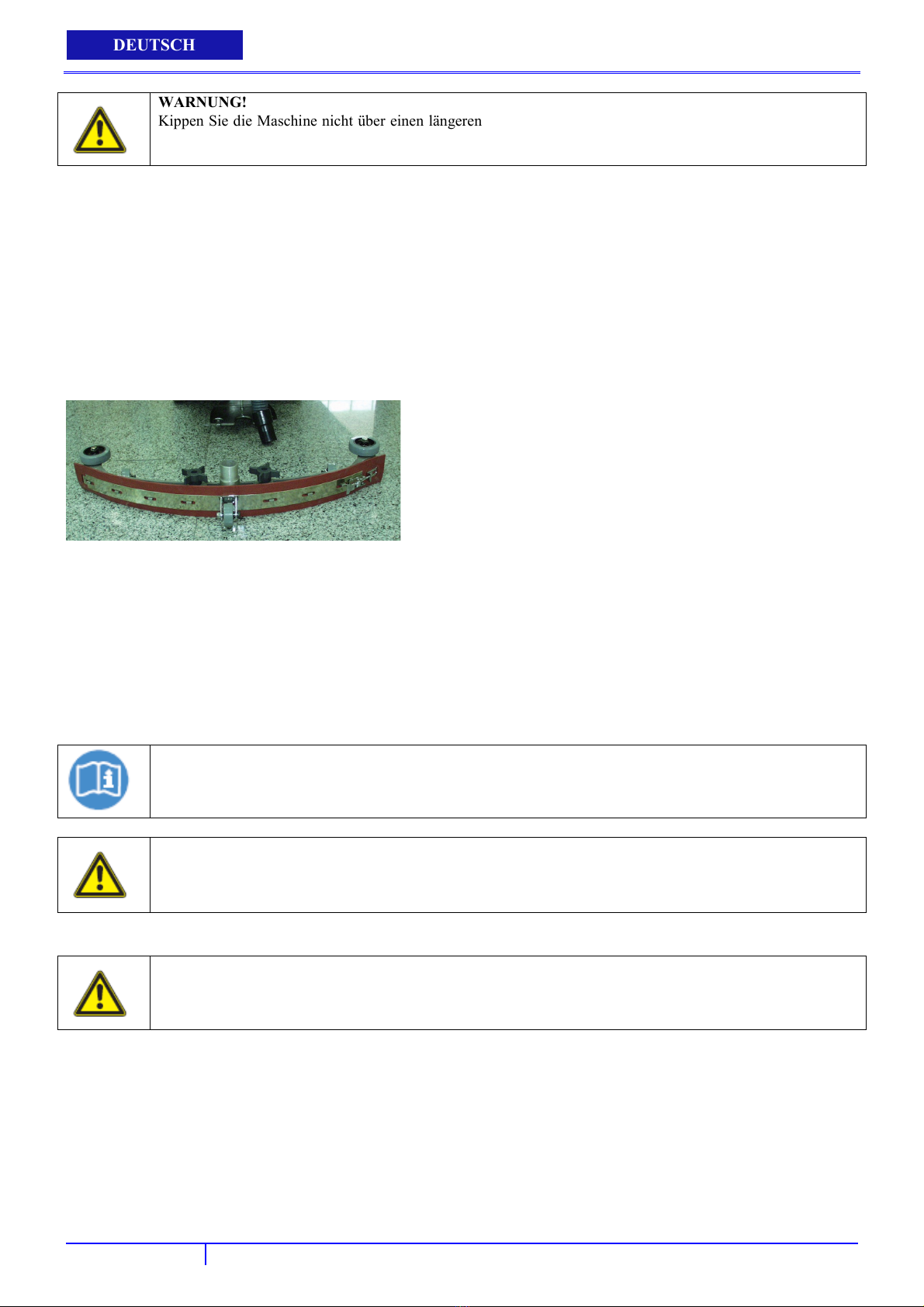
DEUTSCH
WARNUNG!
Kippen Sie die Maschine nicht über einen längeren Zeitraum nach hinten. Dadurch kann Batteriesäure aus den
Batterien auslaufen.
Wird ein Padtriebteller verwendet, muss das Pad zuerst korrekt an die Padtriebtellerfläche angebracht werden.
Montieren Sie den Padtriebteller oder die Bürste an die Antriebsmotornabe, indem Sie die drei Stiftschrauben an den drei
Bohrungen der Antriebsmotornabe ausrichten. Sobald sich diese in den Bohrungen befinden, den Antrieb Richtung
Federverriegelung drehen, um den Antrieb festzustellen.
BETRİEBSANLEİTUNG
DEN GUMMIABZIEHER MONTIEREN
Ziehen Sie den Gummiabzieher-Hubhebel zurück, um die Gummiabzieherhalterung anzuheben.
Lösen Sie die zwei Knöpfe am Gummiabzieher und schieben Sie den Gummiabzieher in die Schlitze an der Rückseite der
Gummiabzieherhalterung. (Die Räder des Gummiabziehers zeigen nach hinten.)
DEN LÖSUNGSTANK BEFÜLLEN
Der Fang 32T-EU kann an zwei Stellen befüllt werden:
a. Der vordere Bereich dient der Befüllung mit einem Schlauch oder Eimer.
b. Der hintere Bereich kann nur mit einem Schlauch befüllt werden.
Bestimmen Sie, welcher Befüllbereich für das Befüllen der Maschine mit Wasser verwendet werden soll.
Befüllen Sie den Tank mit bis zu 52 Liter Wasser. (Die Wassertemperatur sollte 40 °C nicht überschreiten.) Das
transparente Rohr hinten links an der Maschine zeigt über eine Gallonenmarkierung den Wasserstand des
Lösungstanks an.
HINWEIS
Wenn Sie den Lösungstank mit einem Eimer auffüllen, bitte sicherstellen, dass der Eimer sauber ist. Dadurch
wird verhindert, dass Verschmutzungen die Leitungen des Magnetventils verstopfen.
WARNUNG!
Füllen Sie keine brennbaren Materialien in den Lösungstank. Dies kann eine Explosion oder einen Brand
auslösen. Verwenden Sie nur empfohlene Reinigungschemikalien.
Wenden Sie sich für Empfehlungen geeigneter Chemikalien an Ihren Vertrieb von Hausmeisterartikeln.
DIE MASCHINE STARTEN UND STOPPEN
WARNUNG!
Die Maschine darf nicht betrieben werden, es sei denn, Sie haben dieses Handbuch gelesen und verstanden.
Stellen Sie das Steuergehäuse auf eine angenehme Höhe ein, indem Sie die beiden Daumenhebel (16) direkt unter dem
Gehäuse zusammendrücken.
Senken Sie die Gummiabzieherbaugruppe auf den Boden ab, indem Sie den Hubhebel (14) aus der verriegelten Position
freigeben.
Senken Sie die Bürstenkopfbaugruppe auf den Boden ab, indem sie den Bürstendruckschalter (7) auf die Position AN
stellen.
Schalten Sie den Vakuummotorschalter (1) auf die Position „AN“.
Schalten Sie den Bürstenmotorschalter (2) auf die Position „AN“.
Schalten Sie den Lösungsschalter (5) auf die Position „AN“.
a. Die Lösung wird nicht fließen, bis der Betriebsauslöser gezogen wird.
40
Page 43

USER MANUAL
Der Fang 32T-EU verfügt über einen Eigenantrieb. Die Geschwindigkeit kann über einen Knopf (9) an der rechten Seite
des Steuergehäuses geregelt werden.
Der Fang 32T-EU verfügt über einen Rückwärtsgang. Der Rückwärtsgang wird über einen Kippschalter (20) an der
linken Seite des Steuergehäuses aktiviert.
Ziehen Sie zum Beginnen des Schrubbens an einem oder beiden roten Betriebsauslösern (27). Werden diese Auslöser
gezogen, beginnt sich die Bürste zu drehen und die Lösung fließt.
Der FANG32T-EU treibt sich selbst an. Der FANG32T-EU beginnt mit dem Schrubben, wenn die Maschine vorwärts
bewegt wird.
WARNUNG!
Belassen Sie die Maschine mit sich drehender/m Pad/Bürste nicht in derselben Position, da dies den Boden
beschädigen könnte.
Regeln Sie die ausfließende Lösungsmenge, indem Sie am Lösungssteuerknopf (8) drehen. Ein Drehen nach rechts sorgt
für mehr Lösung, ein Drehen nach links für weniger Lösung.
HINWEIS
Für korrektes Schrubben/Trocknen von Böden an den Seiten von Wänden empfiehlt Viper, sich, wie abgebildet,
den Wänden mit der rechten Seite der Maschine anzunähern.
DEUTSCH
VORSICHT!
Bleibt die Maschine an einer Stelle stehen, die Bürsten-/Pad-Halterung zur Vermeidung von Schäden an
Bodenflächen ausschalten, insbesondere wenn die Extradruck-Funktion aktiviert ist.
REGELN DES LÖSUNGSAUSSTROMS
Schalten Sie den Lösungsschalter (A) auf die Position „AN“.
Regeln Sie die ausfließende Lösungsmenge, indem Sie am Lösungssteuerknopf (B) drehen. Ein Drehen nach rechts (im
Uhrzeigersinn) sorgt für mehr Lösung, ein Drehen nach links (gegen den Uhrzeigersinn) für weniger Lösung.
Der Stift (C) zeigt die Endposition des Lösungsregelknopfes (B) an.
HINWEIS
Auch wenn Sie den Lösungsschalter (A) aktivierten, fließt die Lösung nicht, bis der Betriebsauslöser gezogen
wird.
41
Page 44

DEUTSCH
BETRİEBSANLEİTUNG
BATTERIEENTLADUNG WÄHREND DES BETRIEBS
Solange die grüne Warnanzeige (3) leuchtet, betreiben die Batterien die Maschine wie üblich.
Erlischt die grüne Warnanzeige (3) und leuchtet die gelbe Warnanzeige (3) auf, ist es ratsam, die Batterien aufzuladen,
da der Rest-Autonomie nur noch für wenige Minuten ausreicht (in Abhängigkeit von den Batteriemerkmalen und der
durchgeführten Arbeit).
Wenn die rote Warnanzeige (3) aufleuchtet, ist die Autonomie beendet. Nach ein paar Sekunden wird die
Bürsten-/Pad-Halterung automatisch ausgeschaltet, während das Vakuum- und das Antriebssystem eingeschaltet
bleiben, um das Trocknen des Bodens zu beenden und die Maschine zur ausgewiesenen Ladestelle zu fahren.
VORSICHT!
Verwenden Sie die Maschine nicht mit entladenen Batterien, um Schäden an den Batterien und die
Verringerung der Batterielebensdauer zu verhindern.
WÄHEND DES MASCHINENBETRIEBS
Schauen Sie gelegentlich durch den transparenten Schmutzwasserdeckel, um nach möglicher Schaumentwicklung zu sehen.
Füllen Sie einen Entschäumer in den Schmutzwassertank, wenn übermäßig viel Schaum vorhanden ist.
WARNUNG!
Schaum darf nicht in das Abschaltsystem mit Schwimmer eindringen, da sonst der Vakuummotor beschädigt
werden könnte. Durch Schaum wird das Abschaltsystem mit Schwimmer nicht aktiviert.
Schauen Sie sich gelegentlich das transparente Rohr hinten links an der Maschine an, um die Menge an in der Maschine
verbliebener Reinigungslösung zu überprüfen.
Überprüfen Sie gelegentlich den Batteriestatus (3). Zeigt das Messgerät rot an, müssen die Batterien aufgeladen werden.
WARNUNG!
Betreiben Sie die Maschine nicht weiter, wenn der Batteriestatus auf Rot steht. Die Batterie nimmt dadurch
Schaden.
Wenn die Gummiabzieherbaugruppe auf dem Boden Streifen hinterlässt, den Gummiabzieher vom Boden abheben und die
Wischer mit einem feuchten Tuch abwischen.
WARNUNG!
Benutzen Sie zum Abwischen oder Entfernen von Verschmutzungen auf den Wischern nicht die Finger, da dies
zu Verletzungen führen könnte.
Schalten Sie den Bürsten- und Lösungsschalter aus, wenn der Lösungstank leer ist, und heben Sie den Bürstenkopf an.
Belassen sie den Gummiabzieher unten und fahren Sie mit dem Absaugen fort, bis alles Schmutzwasser aufgenommen ist.
42
Page 45

USER MANUAL
DEUTSCH
(Zum Entleeren von Schmutzwasser- und Lösungstanks siehe Abschnitt TANKENTLEERUNG.)
HINWEIS
Der Bürstenmotor ist zum Schutz gegen Schäden mit einem Leistungsschalter versehen. Wird dieser
Unterbrecher ausgelöst, kann er nicht sofort wieder aktiviert werden.
Zuerst muss festgestellt werden, wodurch der Leistungsschalter ausgelöst wurde und der Motor muss abkühlen,
bevor der Leistungsschalter wieder aktiviert werden kann.
TANKENTLEERUNG
Schalten Sie die Maschine aus.
Transportieren Sie die Maschine mit dem Gummiabzieher und der Bürste in erhobener Position zum Entleeren des/der
Tanks zum ausgewiesenen Bereich.
ENTLEEREN DES (VERSCHMUTZTEN) SCHMUTZWASSERTANKS
HINWEIS
Nach jedem Schrubben oder nach dem Nachfüllen des Lösungstanks muss der Schmutzwassertank entleert und
gereinigt werden.
WARNUNG!
Wenn der Schmutzwassertank nach dem Nachfüllen des Lösungstanks nicht entleert wird, könnte Schaum oder
Wasser in den Abschaltmechanismus eindringen und den Vakuummotor beschädigen.
Nehmen Sie den Ablaufschlauch aus der Halterung und halten Sie den Ablaufschlauch über den Bodenabguss. Drehen
Sie den Stecker des Ablaufschlauchs ab, um mit dem Entleeren zu beginnen.
Zum vollständigen Entleeren des Schmutzwassertanks das Scharnier des Schmutzwassertanks öffnen und dieses auf dem
Ständer ruhen lassen.
Reinigen Sie den Schmutzwassertank nach jedem Gebrauch. Spülen Sie den Schmutzwassertank mithilfe eines
Frischwasserschlauchs aus. Achten Sie darauf, kein Wasser in den Abschaltmechanismus mit Schwimmer zu spritzen.
HINWEIS
Wird die Maschine über einen längeren Zeitraum gelagert, darf der transparente Deckel des
Schmutzerwassertanks nie am Tank belassen werden, damit der Tank vollständig trocknet und sich keine
Gerüche bilden.
Bringen Sie den Stecker des Ablaufschlauchs nach der Tankentleerung wieder fest an.
ENTLEERUNG DES (SAUBEREN) LÖSUNGSTANKS
HINWEIS
Nach jedem Schrubben sollte der Lösungstanks entleert und gereinigt werden.
Ziehen Sie das transparente Rohr (hinten links an der Maschine) nach unten, um es von der Schlauchtülle anzunehmen.
Dadurch kann die Lösung frei in einen Eimer oder Bodenabguss fließen.
Spülen Sie den Lösungstank nach jedem Gebrauch mit klarem Wasser aus. Dadurch werden Ablagerungen von
Chemikalien und das Verstopfen der Lösungsleitungen verhindert.
Schalten Sie die Maschine mit Wasser im Lösungstank ein, schalten Sie den Lösungsschalter „an“ und ziehen Sie die
Betriebsauslöser. Dadurch wird das Leitungssystem mit klarem Wasser gespült und gereinigt.
Sobald der Tank gespült, gereinigt und entleert ist, kann das transparente Rohr wieder an die Schlauchtülle angebracht
werden. Vergewissern Sie sich, dass das Rohr an der Schlauchtülle vollständig nach oben geschoben ist.
AUFLADEN DER BATTERIE
HINWEIS
Für eine optimale Maschinenleistung müssen die Batterien die ganze Zeit über aufgeladen sein. Sie sollten nicht
in entladenem Zustand belassen werden.
INWEIS
H
Wurde bei der Maschine ein optionales Batterieladegerät installiert, kann die Batterie ohne angeschlossenes
Ladegerät nicht betrieben werden.
Wenden Sie sich im Fall einer Fehlfunktion des Batterieladegeräts an ein autorisiertes Kundendienstcenter.
43
Page 46
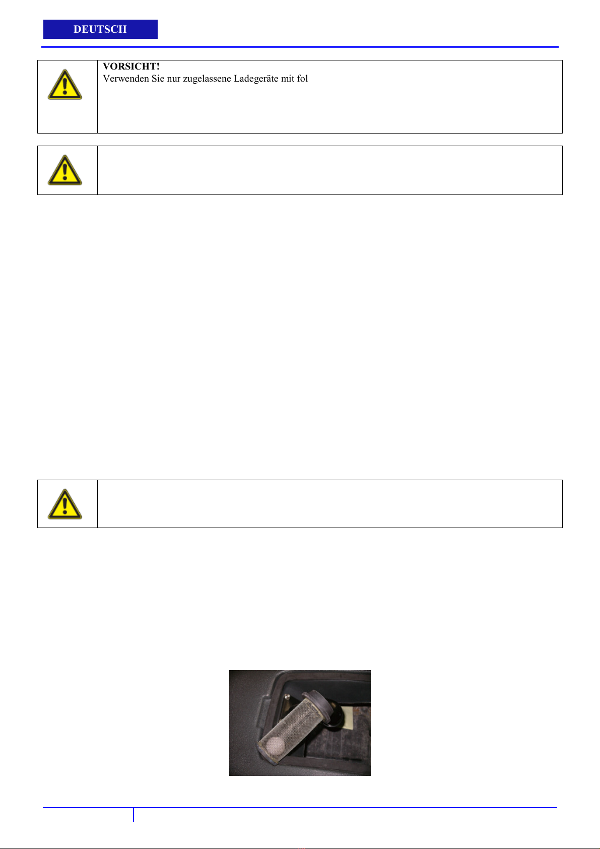
DEUTSCH
VORSICHT!
Verwenden Sie nur zugelassene Ladegeräte mit folgenden Spezifikationen:
● Automatische Stromabschaltung
● Tiefenzyklus-Aufladung
Ausgabestrom von 25 – 35A
●
Ausgabespannung von 36 Volt
●
VORSICHT!
Batterien sind gefährlich! Batterien emittieren Wasserstoff, was zu einer Explosion oder einem Brand führen
kann. Halten Sie Funken und Flammen zu allen Zeiten von den Batterien fern.
Wenn die Maschine aufgeladen wird, muss sichergestellt werden, dass das Batteriefach geöffnet ist.
Stellen Sie das Ladegerät und die Maschine in einen gut belüfteten Bereich.
Schalten Sie die Maschine aus.
Heben Sie den Schmutzwassertank ab und legen Sie das Batteriefach frei.
Überprüfen Sie den Flüssigkeitsstand in jeder Batteriezelle. Laden Sie die Batterien nur auf, wenn die Flüssigkeit die
Batterieplatten leicht bedeckt. Die Batterien dürfen nicht überfüllt werden.
Ein Überfüllen kann zum Überlaufen der Batterien führen, die sich während des Ladens ausdehnen. Bringen Sie die
Kappen vor dem Laden wieder an.
Schließen sie ein zugelassenes Ladegerät an eine geerdete Wandsteckdose an, bevor Sie das Ladegerät an die Maschine
anschließen.
Schließen Sie das Ladegerät an den roten Ladeanschluss vorne links am Batteriefach an.
Klappen Sie den “Kickständer” des Schmutzwassertanks nach oben und legen Sie den Schmutzwassertank vorsichtig auf
dem Ständer ab.
Das Batterieladegerät beginnt automatisch mit dem Laden der Batterien und beendet dieses auch automatische, sobald die
Batterien vollständig aufgeladen sind.
Trennen Sie nach vollständigem Ladevorgang zuerst das Ladegerät von der Wandsteckdose und trennen Sie anschließend
das Ladegerät von der Maschine.
Überprüfen Sie nach vollständigem Ladevorgang den Batterieflüssigkeitsstand. Ist der Flüssigkeitsstand niedrig, muss
destilliertes Wasser nachgefüllt werden, bis der Flüssigkeitsstand den Boden der Sichtrohre erreicht.
Bringen Sie die Kappen wieder an und wischen Sie die Batterien mit einem Tuch trocken.
BETRİEBSANLEİTUNG
WARTUNG
Damit die Maschinen Ihnen viele Jahre gute Dienste leistet, beachten Sie bitte folgende Wartungsverfahren.
VORSICHT!
Vergewissern Sie sich immer, dass die Maschine ausgeschaltet und das Batteriekabel abgetrennt ist, bevor Sie
Wartungs- und Reparaturarbeiten vornehmen.
TÄGLICHE INSTANDHALTUNG
Padtriebteller/Bürste abnehmen und mit einem zugelassenen Reinigungsmittel säubern.
Schmutzwasser- und Lösungstanks vollständig entleeren und mit klarem Wasser ausspülen. Führen Sie eine Sichtprüfung
des Schmutzwassertanks auf Ablagerungen durch und reinigen Sie ihn wenn nötig.
Die Gummiabzieherbaugruppe vom Boden abheben und mit einem feuchten Tuch abwischen. Stellen Sie sicher, dass der
Gummiabzieher in erhobener Position gelagert wird.
Nehmen Sie die Abschaltbaugruppe mit Schwimmer ab und spülen Sie diese mit klarem Wasser aus.
Reinigen Sie die Maschine mit einem zugelassenen Reinigungsmittel und einem feuchten Tuch. Das Maschinenäußere
darf zum Reinigen nicht mit Wasser besprüht werden, damit Motor und Leitungen nicht beschädigt werden.
Batterien aufladen.
44
Page 47
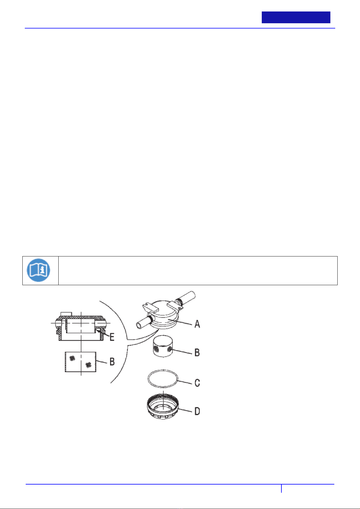
USER MANUAL
DEUTSCH
WÖCHENTLICHE INSTANDHALTUNG
Flüssigkeitsstand in den Batterien überprüfen.
Die Batterien auf lose oder korrodierte Kabel überprüfen.
Die Batterienoberseiten frei von Korrosion halten.
MONATLICHE INSTANDHALTUNG
Überprüfen Sie die Maschine auf Lecks und lose Befestigungsteile.
Schmieren sie alle Schmierstellen und Drehpunkte mit Silikonspray und zugelassenem Fett.
Stellen Sie die Maschine über einen Bodenabguss. Spülen Sie das Lösungssystem durch, indem Sie 10 Liter heißes
Wasser und zugelassenes alkalisches Reinigungsmittel in den Lösungstank schütten und die Maschine (mit
eingeschaltetem Lösungsregler) für 45 Sekunden laufen lassen.
Die Maschine ausschalten und über Nacht ruhen lassen. Entleeren Sie die verbleibende Lösung am nächsten Tag und spülen
Sie den Lösungstank mit klarem Wasser aus.
REINIGUNG DES MOTORFILTERS DES VAKUUMSYSTEMS
Fahren Sie die Maschine auf eine ebene Bodenfläche.
Den Zündschlüssel (19) auf „AUS“ drehen.
Den Schmutzwassertank öffnen.
Gegebenenfalls das Wasser aus dem Tank lassen, um den Filter freizulegen.
Überprüfen, ob der Vorfilter sauber ist. Wenn nötig, diesen mit Wasser und Druckluft reinigen und wieder einsetzen.
Führen Sie die Schritte 1, 2 und 3 in umgekehrter Reihenfolge durch.
LÖSUNGS-/FRISCHWASSER-FILTERREINIGUNG
Fahren Sie die Maschine auf eine ebene Bodenfläche.
Den Zündschlüssel (19) auf „AUS“ drehen.
Nehmen Sie die transparente Abdeckung (D) (der Wasserfilter befindet sich unter der Maschine) ab und entfernen Sie
anschließend das Filtersieb (B). Beides reinigen und auf den Ständer legen (A).
HINWEIS
Das Filtersieb (B) muss korrekt am Gehäuse (E) des Ständers (A) angebracht werden.
ÜBERPRÜFUNG UND AUSTAUSCH DES GUMMIABZIEHERWISCHERS
einigen sie den Gummiabzieher wie im vorigen Abschnitt gezeigt.
R
Überprüfen Sie, ob sich die Kante (M) des vorderen Wischers (D) und die Kante (L) des hinteren Wischers (E) auf ganzer
Länge auf derselben Ebene befindet.
Stellen Sie deren Höhe andernfalls wie folgt ein:
− Lösen Sie die Halterungen (A), um den hinteren Wischer (E) einzustellen; Halterungen wieder befestigen.
45
Page 48

DEUTSCH
Bürstenmotor läuft
− Lösen Sie die Handräder (G) und stellen sie den vorderen Wischer (D) ein; Halterungen wieder befestigen.
Überprüfen sie den vorderen Wischer (D) und hinteren Wischer (E) auf Unversehrtheit, Schnitte und Risse; wenn nötig,
wie unten dargestellt austauschen.
Stellen Sie sicher, dass die vordere Ecke (N) des hinteren Wischers nicht verschlissen ist; drehen Sie den Wischer
andernfalls um, um die verschlissene Ecke gegen eine intakte auszutauschen.
Sind auch die anderen Ecken verschlissen, den Wischer wie folgt austauschen:
− Lösen Sie die Halterungen (A) und nehmen Sie das Halterungsband (B) ab, anschließend kann der hintere Wischer (E)
ausgetauscht/umgedreht werden. Installieren Sie den Wischer, indem sie die Schritte zum Abnehmen in umgekehrter
Reihenfolge durchführen.
− Drehen Sie die Handräder (G) ab und entnehmen Sie das Halterungsband (H); tauschen Sie nun den vorderen Wischer
(D) aus. Montieren Sie den Wischer, indem sie die Schritte zum Abnehmen in umgekehrter Reihenfolge durchführen.
Die Höhe, wie im vorigen Schritt gezeigt, nach dem Austausch (oder Umdrehen) der Wischer einstellen.
Schließen Sie den Vakuumschlauch (32) an den Gummiabzieher an.
Montieren Sie den Gummiabzieher (12) und drehen Sie die Handräder (13) herunter.
Wenn nötig, das Gummiabzieher-Einstellhandrad (13) anpassen.
BETRİEBSANLEİTUNG
BÜRSTEN-/PAD-REINIGUNG
VORSICHT!
Schneidegefahr.
Es ist ratsam, bei der Reinigung von Bürste/Pad Schutzhandschuhe zu tragen, da scharfe Ablagerungen
vorhanden sein können.
Entfernen Sie die Bürste/das Pad von der Maschine, wie im Kapitel Gebrauch gezeigt.
Bürste/Pad mit Wasser und Reinigungsmittel reinigen und abwaschen.
Bürste/Pad auf Unversehrtheit und übermäßige Verschleißspuren hin überprüfen; wenn nötig austauschen.
PROBLEMBEHEBUNG
PROBLEM URSACHE LÖSUNG
Schlechter Bürstenschalter Viper-Händler kontaktieren
nicht
Bürsten-Leistungsschalter hat ausgelöst Bürstenmotor auf Blockierungen überprüfen und
Gleichrichter ist durchgebrannt Viper-Händler kontaktieren
Schlechte Verkabelung Viper-Händler kontaktieren
Schlechter Bürstenmotor Viper-Händler kontaktieren
Kohlebürsten verschlissen Viper-Händler kontaktieren
Schlechtes Magnetventil Viper-Händler kontaktieren
46
Page 49

Vakuummotor läuft
Geringer oder kein
USER MANUAL
PROBLEM URSACHE LÖSUNG
Schlechter Vakuumschalter Viper-Händler kontaktieren
nicht
Kurze Laufzeit Batterien müssen aufgeladen werden Batterien aufladen (siehe Batterien aufladen)
Lösungsausstrom
Schlechte
Wasseraufnahme
Schlechte Verkabelung Viper-Händler kontaktieren
Schlechter Vakuummotor Viper-Händler kontaktieren
Kohlebürsten verschlissen Viper-Händler kontaktieren
Batterien benötigen Wartung Siehe Batterienwartung in dieser Anleitung
Schlechte Batteriezellen Batterien austauschen
Schlechtes Ladegerät Ladegerät ersetzen
Schlechter Lösungs-Schalter Viper-Händler kontaktieren
Verstopftes Magnetventil Viper-Händler kontaktieren
Verstopfter Lösungsfilter Filter entnehmen und reinigen
Lösungsleitung blockiert Lösungsleitung entnehmen und reinigen
Der Regelknopf für den Lösungsausstrom muss
eingestellt werden
Gummianzieher blockiert Gummiabzieher von Schmutz befreien
Gummianzieherwischer verschlissen Neue Gummiabzieherwischer installieren
Gummianzieher nicht korrekt angebracht Sicherstellen, dass die
Vakuumschläuche weisen Löcher auf oder sind
lose
Lösungsausstrom erhöhen, indem der Regelknopf
nach rechts gedreht wird. Verringern, indem der
Regelknopf nach links gedreht wird.
Gummianzieher-Wischerbaugruppe fest angebracht
und nicht lose ist.
Schlauchanschlüsse auf Sitzfestigkeit prüfen.
Beschädigte Schläuche austauschen.
DEUTSCH
LAGERUNG
Lagern Sie die Maschine an einem trockenen, frostgeschützten Ort.
Die Lagertemperatur der Maschine muss zwischen 0 °C und +40 °C liegen.
Lagern Sie die Maschine immer in Innenbereichen.
Nehmen Sie Bürste/Pad immer ab.
Lagern Sie die Maschine immer mit vom Boden abgehobenem Gummiabzieher.
Wenn die Maschine in einem Bereich gelagert wird, der Temperaturen unter dem Gefrierpunkt erreichen kann, vor der
Lagerung sicherstellen, dass alle Flüssigkeiten aus der Maschine abgelassen wurden. Jeglicher Schaden durch
Temperaturen unter dem Gefrierpunkt wird von der Gewährleistung nicht abgedeckt.
Entleeren Sie den Schmutzwassertank und entfernen Sie die transparente Abdeckung des Schmutzwassertanks, damit
Vakkumschlauch könnte blockiert sein Schlauch überprüfen und Schmutz entfernen
Ablaufschlauchverriegelung locker Ablaufstecker befestigen.
Batterien müssen aufgeladen werden Batterien aufladen (siehe Batterien aufladen)
Vakuummotor lose Montageschrauben des Vakuummotors festziehen.
Nicht überdrehen, um Schäden zu vermeiden.
Schmutzwassertank sitzt locker Sicherstellen, das der transparente
Schmutzwassertankdeckel fest sitzt.
Eingangsöffnung des Schmutzwassertanks
verstopft
Schmutzwassertank voll Schmutzwassertank leeren
Abschaltmechanismus verstopft Abschaltmechanismus aus dem
VORSICHT!
Wird die Maschine in Bereichen gelagert, die Temperaturen unter dem Gefrierpunkt erreichen könnten,
sicherstellen, dass sowohl Tank als auf Lösungsleitungen frei von Wasser und trocken sind!
Schmutzwassertank entleeren und Tank auf die
Seite kippen. Eingangsöffnung auf Schmutz
untersuchen und solchen entfernen.
Schmutzwassertank entnehmen und Schmutz
entfernen.
47
Page 50

DEUTSCH
dieser während der Lagerung “atmen” kann.
Lassen Sie alle Flüssigkeit aus dem Lösungstank ab.
BETRİEBSANLEİTUNG
RECYCLING DER REINIGUNGSMASCHINE
Machen Sie die ausgediente Reinigungsmaschine umgehend unbrauchbar:
Batterien entnehmen.
Elektrische Geräte nicht zusammen mit Haushaltsabfällen entsorgen.
Wie in der europäischen Richtlinie 2002/96/EC für Elektro- und Elektronik-Altgeräte ausgeführt, müssen
elektrische Geräte separat gesammelt und ökologisch recycelt werden.
Erkundigen Sie sich nach weiteren Informationen bei Ihren örtlichen Behörden oder Ihrem nächstgelegenen
Händler
48
Page 51

Manuel d’utilisation
FRANÇAİS
TABLE DES MATIÈRES
INTRODUCTION ........ …………………………………………………………………………………………………………50
USAGE DU MANUEL ET CONTENU…………………………………………………………………………………50
CIBLE(BUT) USAGE DU MANUEL ET CONTENU……………………………………………………………………50
COMMENT GARDER ET TENIR CE MANUEL USAGE DU MANUEL ET CONTENU……………………………50
DÉCLARATION DE CONFORMITÉUSAGE DU MANUEL ET CONTENU…………………………………………50
DONNEES D'IDENTIFICATION USAGE DU MANUEL ET CONTENU……………………………………………50
AUTRES MANUELS DE RECOMMANDATION USAGE DU MANUEL ET CONTENU……………………………50
PIECES DE RECHANGE ET ENTRETIEN USAGE DU MANUEL ET CONTENU…………………………………50
MODIFICATIONS ET AMELIORATIONS USAGE DU MANUEL ET CONTENU……………………………………50
USAGE ET DESTINATION USAGE DU MANUEL ET CONTENU……………………………………………………50
CONVENTIONS USAGE DU MANUEL ET CONTENU………………………………………………………………51
DEBALLAGE / LIVRAISON .................................................................................................................................................... 51
SÉCURITÉ .................................................................................................................................................................................. 51
SYMBOLES UTILISES INDIQUANT DES INSTRUCTIONS USAGE DU MANUEL ET CONTENU………………51
INSTRUCTIONS GÉNÉRALES USAGE DU MANUEL ET CONTENU………………………………………………52
DESCRIPTION DE LA MACHINE .......................................................................................................................................... 55
STRUCTURE DE LA MACHINE USAGE DU MANUEL ET CONTENU……………………………………………55
ACCESSOIRES / OPTIONS USAGE DU MANUEL ET CONTENU……………………………………………………56
SCHEMA DE CABLAGE (FANG32T-EU ) USAGE DU MANUEL ET CONTENU……………………………………58
FONCTIONNEMENT ................................................................................................................................................................ 59
AVANT DE METTRE LA MACHINE EN MARCHE USAGE DU MANUEL ET CONTENU…………………………59
LORS DU FONCTIONNEMENT DE LA MACHINE USAGE DU MANUEL ET CONTENU………………………63
ENTRETIEN ............................................................................................................................................................................... 65
ENTRETIEN QUOTIDIEN USAGE DU MANUEL ET CONTENU……………………………………………………65
ENTRETIEN HEBDOMADAIRE USAGE DU MANUEL ET CONTENU…………………………………………66
ENTRETIEN MENSUEL USAGE DU MANUEL ET CONTENU………………………………………………………66
NETTOYAGE DU FILTRE DU MOTEUR D'ASPIRATEUR USAGE DU MANUEL ET CONTENU…………………66
SOLUTION / NETTOYAGE FILTRE D'EAU PROPRE DE NETTOYAGE USAGE DU MANUEL ET CONTEN……66
VERIFICATION DE LA LAME DU BALAI_EPONGE ET REMPLACEMENT USAGE DU MANUEL ET CONTENU
USAGE DU MANUEL ET CONTENU…………………………………………………………………………………66
BROSSE / NETTOYAGE DE PLAQUETTE USAGE DU MANUEL ET CONTENU………………………………67
DEPANNAGE ............................................................................................................................................................................ 67
STOCKAGE ................................................................................................................................................................................ 68
RECYCLAGE DU FILTRE ....................................................................................................................................................... 69
49
Page 52

FRANÇAİS
MANUEL D’UTİLİSATİON
INTRODUCTION
NOTE
Les chiffres entre parenthèses renvoient aux éléments indiqués dans le chapitre Description de la machine.
USAGE DU MANUEL ET CONTENU
Ce manuel a pour but de fournir à l'opérateur toutes les informations nécessaires afin d’utiliser la machine correctement, et d’une
façon assurée et autonome. Il a pour contenu des informations sur les données techniques, de sécurité, de fonctionnement, de
stockage, de maintenance, de pièces détachées et d'élimination. Avant d'effectuer toute utilisation sur la machine, les utilisateurs
et les techniciens qualifiés doivent lire attentivement ce manuel. En cas de doute concernant l'interprétation des instructions et
pour n’importe quelle information complémentaire, veuillez contactez-Viper
CIBLE
Ce manuel est destiné aux opérateurs et techniciens qualifiés pour effectuer l'entretien de la machine.
Les opérateurs ne doivent pas effectuer les procédures réservées à des techniciens qualifiés. En cas des dommages provenant du
non-respect de cette interdiction, VIPER ne sera pas responsable.
COMMENT GARDER ET TENIR CE MANUEL
Le manuel d'utilisation doit être tenu prêt de la machine, dans une enveloppe spéciale, loin Des liquides humides et d'autres
substances qui peuvent l’abîmer.
DÉCLARATION DE CONFORMITÉ
La déclaration de conformité, fournie avec la machine, certifie la conformité de la machine avec la législation en vigueur.
NOTE
Deux exemplaires de la déclaration originale de conformité sont fournis avec la documentation de la machine.
La déclaration CE est imprimé pour le Guide d’un démarrage rapide.
DONNEES D'IDENTIFICATION
Le modèle et le numéro de série sont indiqués dans le plateau disque.
Servez vous de cette information en cas de besoin des pièces de cette machine. Utilisez le tableau suivant pour noter les données
d'identification de la machine.
Modèle de la machine ...............................................................................
Numéro de série de la machine..................................................................
AUTRES MANUELS DE RECOMMANDATION
-
Service Manuel (peut être consulté dans les centres de service Viper)
-
Liste des pièces détachées (voir le site : www.vipercleaning.eu)
PIECES DE RECHANGE ET ENTRETIEN
Toutes les procédures nécessaires d'exploitation, d'entretien et de réparation doivent être effectuées par un personnel qualifié ou
par les centres de service Vipère. Seules les pièces de rechange originales et les accessoires doivent être utilisés. Pour un service
ou commande de pièces de rechange et accessoires, veuillez contactez Vipère, en précisant le modèle et le numéro de série
MODIFICATIONS ET AMELIORATIONS
Vipère améliore constamment ses produits et réserve son droit de faire des changements et améliorations a sa discrétion sans être
oblige de faire des applications de telles bénéfices des machines qui ont été précédemment vendues.
Toute modification et / ou l'ajout d'accessoires doit être approuvé(e) et réalisé(e) par VIPER.
USAGE ET DESTINATION
Toutes les machines de nettoyage automatiques sont exclusivement consacrées pour utilisation humide des revêtements de sol
qui résistent à l'eau à l'intérieur des bâtiments .Les machines de nettoyage automatique ne peuvent pas être utilisées pour
50
Page 53

MANUEL D’UTİLİSATİON
moquette et nettoyage de tapis.
Cet appareil est conçu pour une utilisation commerciale, par exemple dans les hôtels, les écoles, les hôpitaux, les usines, les
magasins, les bureaux et les entreprises de location.
Toute autre utilisation est considérée comme non conforme. Le fabricant refuse toute responsabilité pour tout dommage résultant
d'une telle utilisation. Le risque pour une telle utilisation cause à la charge unique de l'utilisateur.
Une bonne utilisation comprend aussi un bon fonctionnement, l'entretien et les réparations telles que spécifiées par le fabricant.
Les modifications apportées aux machines automatiques par les utilisateurs eux-mêmes excluent la responsabilité du fabricant
pour tout dommage qui en résulte.
Le revêtement de sol doit être contrôle par rapport à la pertinence de cette méthode de nettoyage avant l'utilisation de la machine!
Noter la pression à la surface en cas des moments des étages élastiques, par exemple, dans les gymnases!
Le fabricant ne prends aucune responsabilité en cas des dommages à la machine et le revêtement de sol à nettoyer ,qui est
causée par l'utilisation des mauvais balais et produits de nettoyage.
FRANÇAİS
CONVENTIONS
Vers l’avant, l’arrière, en face, derrière, a gauche ou a droite et en haut sont destinés en référence à la position de l'opérateur,
c'est-à-dire en suivant la position du travail.
DEBALLAGE / LIVRAISON
Suivez attentivement les instructions sur l'emballage pour déballer la machine
Lorsque la machine est livrée, vérifier que l'emballage et la machine n'ont pas été endommagés pendant le transport. Dans le cas
ou vous observez des dommages, gardez l'emballage et faites-le vérifier par le transporteur qui l'a livré. Appelez le(transporteur)
immédiatement pour remplir un formulaire de réclamation.
Vérifiez le contenu du paquet afin de s'assurer que les éléments suivants sont inclus:
-
Machine
-
Montage du balai-eponge
-
Conducteur de brosse (et pilote de la plaquette)
SÉCURITÉ
Les symboles suivants indiquent les situations potentiellement dangereuses. Il faut toujours lire attentivement ces informations et
prendre toutes les précautions afin de protéger les personnes et les biens.
La coopération de l'opérateur est essentielle pour prévenir les blessures. Sans la coopération complète de la personne responsable
du fonctionnement de la machine ,il n’y a aucun programme de prévention des accidents en vigueur. La plupart des accidents qui
peuvent survenir dans une entreprise, tout en travaillant ou en bougeant autour,en général sont dus au non-respect des règles de
prudence et même des plus simples .Un opérateur prudent et avisé est bien protégé contre les accidents et c’est très important
pour la réussite de tout programme de prévention.
SYMBOLES UTILISES INDIQUANT DES INSTRUCTIONS
DANGER!
Un danger qui mène directement à des blessures graves ou irréversibles,ou même au décès.
AVERTISSEMENT!
Un danger qui peut entraîner des blessures graves ou même au décès.
ATTENTION!
Un danger qui peut entraîner des blessures légères ou des dommages.
51
Page 54

FRANÇAİS
MANUEL D’UTİLİSATİON
NOTE
Indique une remarque sur des fonctions importants (clés)
INSTRUCTIONS GÉNÉRALES
Des avertissements et des précautions spécifiques sont indiqués ci-dessous pour informer sur les dommages importants aux
personnes et a la machine
L'appareil doit
-
Etre utilisé seulement par les personnes qui ont été informés par l’utilisation correcte et explicitement demandé à la
tâche de son fonctionnement.
-
Ne doit être utilisé que sous la supervision
-
Ne peut pas être utilisé par des enfants
Le lieu de travail est derrière l’aspirateur.
Ne pas utiliser de dangereuses techniques de travail
Toujours guider l’aspirateur en utilisant les deux mains sur la poignée.
Lorsque l'aspirateur est à l'arrêt, éteignez l’unité de brosse immédiatement pour éviter d'endommager le revêtement du sol.
Eteignez l'appareil et débranchez la prise de la batterie dans les cas suivants:
-
Avant de nettoyer et d'entretenir
-
Avant de remplacer des composants
-
Avant de changer sur l'appareil
L'utilisation de l'aspirateur est soumise à la réglementation en vigueur. Outre que les instructions de service et de prévention des
accidents contraignant les régulations en vigueur dans le pays d'utilisation,il faut respecter les règles reconnues pour un travail
sûr et convenable.
TRANSPORT
Lors du transport de l'aspirateur dans les ascenseurs
-
Respectez les règles de sécurité en vigueur, en particulier en ce qui concerne la capacité de charge.
FONCTIONNEMENT
Afin d'empêcher une utilisation non autorisée de l’appareil, la source d'alimentation doit être désactivée ou verrouillée en retirant
par exemple la clé de l'interrupteur d'alimentation.
Prenez toutes les précautions nécessaires pour éviter que les cheveux, les bijoux et les vêtements flottants soient saisis par les
pièces en mouvement de la machine.
Avant d'utiliser la machine, fermez toutes les portes et / ou ouvertures.
La température de fonctionnement de la machine doit être comprise entre 0 ° C et +40 °C.
L'humidité doit être comprise entre 30% et 95 %.
N’utilisez pas la machine comme moyen de transport.
En cas d'incendie, utilisez un extincteur à poudre, et non à eau.
Ne jouez pas avec les gardes de sécurité de la machine et suivez scrupuleusement les instructions ordinaires d'entretien.
Ne laissez aucun objet entrer dans les ouvertures. N’utilisez pas la machine si les ouvertures sont obstruées.Gardez toujours les
ouvertures libres de poussière, de poils et de toute autre matière étrangère qui pourrait réduire le flux de l'air.
Ne retirez pas ou altérer les plaques apposées à la machine.
Si la machine est utilisée conformément aux instructions, les vibrations ne sont pas dangereuses. Le niveau de vibrations de la
machine est inférieur à 2.5 m/ s
Les niveaux de vibration de la Main / Bras sont bien en dessous de 2,5 m/ s2 (mesuré selon la norme ISO 5349),qui est la limite
pour une période de fonctionnement en continu de 8 heures.
Cette machine ne doit pas être utilisée sur des routes ou des voies publiques.
52
2
(98/37/EEC-EN 1033/1995).
Page 55

MANUEL D’UTİLİSATİON
Les machines Viper peuvent être utilisées en combinaison avec des détergents standards qui ne peuvent endommager aucun
matériel des machines Viper (Interdit d'utiliser des solvants ou autres matériaux liquides agressifs).Viper ne paiera aucune
réclamation concernant l'utilisation de détergents agressifs dans les machines Viper. Si vous avez besoin d’un produit spécial
pour le nettoyage, contactez s'il vous plaît votre revendeur Viper.
Faites attention lors du transport de la machine lorsque la température est au-dessous du point de congélation. L'eau dans le
réservoir ou dans les tuyaux pourrait geler et endommager sérieusement la machine.
FRANÇAİS
ENTRETIEN
Afin d'assurer un fonctionnement correcte et sur de la machine, l’entretien périodique montré dans le chapitre correspondant de
ce manuel, doit être réalise par le personnel autorisé ou par le centre du service Viper .
Lisez attentivement toutes les instructions avant de passer a la procédure de tout entretien / réparation.
Ne travaillez pas sous la machine soulevée sans l'appuyer par des chandelles.
Ne lavez pas la machine avec des jets d'eau directs ou sous pression ou en utilisant des substances corrosives.
GARANTIE
En ce qui concerne la garantie, nos conditions de commerce général sont applicables.
Les modifications non autorisées sur l'appareil, l'utilisation incorrectes de brosses et de détergents en plus d'utiliser l'appareil
d'une manière autre que pour l'usage prévu exempté Le fabricant se retir de toute responsabilité pour les dommages résultant.
ESSAIS ET APPROBATIONS
Les Essais électriques doivent être effectuées conformément aux dispositions du règlement de sécurité (BGV A3) et à la norme
DIN VDE 0701 partie 1 et partie 3.Conformément à DIN VDE 0702 ces essais doivent être effectués aux intervalles réguliers et
après des réparations ou des modifications.
COMPOSANTS ÉLECTRIQUES
DANGER
Batteries.
Risque d'explosion.
La batterie en charge produit des gaz hydrogène très explosif. Maintenez l'ensemble du réservoir ouvert
au moment du chargement de la batterie et effectuez cette procédure dans des endroits bien aérés et loin
des flammes nues.
Ne laissez pas la machine sans surveillance quand elle est branchée pour réduire le risque d'incendie, du
choc électrique ou de blessure. Avant d'effectuer toute opération d'entretien, débranchez le câble du
chargeur de la batterie du réseau électrique.
Ne fumez pas pendant le chargement des batteries.
L'utilisation de pièces détachées non authentiques, des accessoires, des batteries et des chargeurs peuvent
diminuer la sécurité de l'appareil. Utilisez seulement des pièces détachées et accessoires de Viper et
utilisez des batteries et des chargeurs que VIPER a recommandé. Lors de l'utilisation non certifiée et non
recommandée des batteries et chargeurs, VIPER ne couvre pas le coût des dommages (garantie) causés
par cela.
ATTENTION !
Chargeur de batterie.
Choc électrique due par des secteurs défectueux en liaison avec du plomb ou du câble du chargeur.
Le contact avec un secteur défectueux en liaison avec du plomb ou du câble du chargeur peut entraîner des
blessures graves, voire mortelles.
Éloignez la batterie des étincelles, flammes et de matériel incandescent. Pendant le fonctionnement
normal les gaz explosifs sont relâchés.
Avant l’utilisation du chargeur de la batterie, assurez vous que les valeurs de fréquence et de tension sont
indiquées sur la plaque de numéro série de la machine correspondant à la tension électrique du secteur.
N’endommagez pas le câble d’alimentation électrique (par exemple, en le roulant , tirant ou en
l'écrasant).
Vérifiez régulièrement si le câble d'alimentation est endommagé ou montre des signes de vieillissement.
Les conduites défectueuses câble de raccordement remplacé par votre représentant du service Viper ou
un électricien qualifié avant d'utiliser l'appareil à nouveau.
Ne tirez pas ou transporter la machine par le câble du chargeur de la batterie et n’utilisez jamais le câble
du chargeur de la batterie comme un manche.Ne fermez pas une porte sur le câble du chargeur de la
53
Page 56

FRANÇAİS
MANUEL D’UTİLİSATİON
batterie ou retirer le câble du chargeur de la batterie prêt des bords ou des coins.
Maintenir le câble du chargeur de la batterie à l'écart des surfaces chauffées.
Evitez de charger les batteries si le câble du chargeur de la batterie ou la prise du courant sont
endommagées. Si la machine ne fonctionne pas comme il le faut, si elle a été endommagée, oubliée à
l'extérieur ou si elle est tombée dans l'eau, retournez-la au centre du service.
ESCALIERS ET GRADIENTS
ATTENTION!
Risque de chute et de glissade dans les escaliers et les inclinaisons.
Lors de monter les escaliers et les pentes, il ya un risque de blessures corporelles et des dommages à la propriété.
Ne sautez pas les etapes.
Utilisez l'appareil sur une surface horizontale avec une inclinaison maximale de 2%.
REVÊTEMENTS DU SOL
ATTENTION!
Risque de dégâts sur les revêtements de sol sensibles
Les zones relativement sensibles du revêtement du sol peuvent être endommagées lors du nettoyage
Avant d'utiliser l'aspirateur, vérifiez si les revêtements de sol sont appropries à cette technique de
nettoyage.
Attention aux parties compressives des sols elastiques tels que les salles de gym
Méfiez-vous de la compression au secteur des sols élastiques, par exemple, dans les salles de gym.
Utilisez uniquement des produits de nettoyage approuvés par Viper.
MATIÈRES DANGEREUSES POUR LA SANTE
AVERTISSEMENT
Produit dangereux pour le bien être du revêtement du plancher ou du sol Les revêtements de sol peuvent
contenir des matériaux qui sont dangereux pour la santé, qui se dissolvent au moment du nettoyage.
Ne pas nettoyer les poussières des revêtements de sol par des liquides qui sont dangereux pour la santé
car ils peuvent se dissoudre.
RISQUE D'EXPLOSION
AVERTISSEMENT
Matières inflammables et explosives.
Risque d'explosion dans un atmosphère explosive ou zones où des produits inflammables et explosifs sont
stockées.
Ne faites pas fonctionner l'appareil à proximité des poudres dangereuses, inflammables et / ou
explosives, de liquides ou de vapeurs.
PIECES DETACHEES ET ACCESSOIRES
ATTENTION!
Des composants non authentiques et des détergents inconvenables.
L'utilisation de pièces non authentiques et de détergents inconvenables peut compromettre la sécurité de
l'appareil et conduit aux dégâts.
Utilisez uniquement des pièces détachées et accessoires de Viper.
N'utilisez que les accessoires et détergents fournies avec l'appareil ou de ceux indiqués dans les
instructions d'utilisation.
54
Page 57

MANUEL D’UTİLİSATİON
DESCRIPTION DE LA MACHINE
STRUCTURE DE LA MACHINE
FRANÇAİS
1. Interrupteur marche/arrêt de l’aspirateur
2. Interrupteur de brosse marche/arrêt
3. Indicateur du niveau de la batterie
4. Compteur d'heures
5. Interrupteur de la solution marche/arrêt
6. Brosse de mesure de pression
7. Brosse de pression monter/ descendre
8. Bouton de commande de la solution
9. Bouton de commande de vitesse
10. Tuyau de vidange du réservoir de récupération
11. Disjoncteurs
12. Raclette d’assemblage
13. Raclette de réglage de l’écrou et de l'arbre
14. Levier de raclette de levage
15. Roulettes arrière
16. Levier de console de réglage
17. Visualisation du niveau du tube du réservoir de solution
18. Remplissage de solution arrière
19. Touche de l’interrupteur
20. Interrupteur pour inverser
21. Capot avant
22. Tête de brossage
23. Rouleaux de protection
24. Porte de la tête de brossage
25. Roues de transport
26. Réservoir de solution
27. Gâchette d’exploitation
28. Boîtier de commande
29. Couvercle du réservoir de récupération
30. Assemblage du filtre de la solution
31. Réservoir de récupération
32. Raclette flexible d’aspiration
55
Page 58

FRANÇAİS
MANUEL D’UTİLİSATİON
ACCESSOIRES / OPTIONS
En plus des composants standard, la machine peut être équipée avec les accessoires suivants / options, en fonction de
l'utilisation spécifique de l'ordinateur:
● Brosse
● Conducteur de plaquette
Pour plus amples informations concernant les accessoires optionelles, contactez un revendeur agréé.
CARACTÉRISTIQUES (DONNÉES)TECHNIQUES
FANG 32T-EU
Modèle
(1 brosse /support de plaquette, avec un système de
conduite)
Hauteur de la machine mm
Solution / Capacité du réservoir d'eau propre l
Capacité du réservoir de récupération d'eau l
Diamètre de la roue d'arrière mm 297
Puissance du moteur du système d'aspiration W
Système d'entraînement du moteur électrique W 370
Vitesse du variateur (variable) km/h
Pente franchissable %
Niveau de pression sonore au poste de travail dB(A)
Des batteries standard Ah @ 20 h
Capacité du circuit du système d’aspirateur mm H2O
Largeur de l'aspirateur mm
Largeur du balai-eponge mm
Machine à longueur maximale mm
Largeur de la machine sans le balai mm
Diamètre de la brosse mm
Poids sans batterie et avec réservoirs vides kg
Poids brut
kg
1090
115
106
650
0 – 4.5
2
70
6-6V/305AmP.hR
1,860
800
1020
1690
1050
2*406
200
286
Puissance du moteur de la brosse W 740
Vitesse de la brosse rpm 200
Dimensions du compartiment à batterie
(longueur x largeur x hauteur)
56
mm
580*500*370
Page 59

MANUEL D’UTİLİSATİON
FRANÇAİS
BATTERY CAPACITY LIGHTS
(16AWG GRN)
8
(16AWG WHT)
5
(14AWG RED)
13
(14AWG BLK)
01
(14AWG BLK)
16
(14AWG RED)
15
(16AWG BLU)
18
(16AWG BLU)
17
(16AWG WHT)
1
(12AWG RED)
12
(16AWG BLU)
0
(12AWG RED)
10
(12AWG RED)
10
12
(12AWG RED)
(14AWG RED)
14
(14AWG RED)
20
6V BATTERY
_
6V BATTERY
_
6V BATTERY
+
+
+
_
HOUR
METER
1
CIRCUIT BREAKER
VACUUM
SOLENOID
6V BATTERY
_
6V BATTERY
_
6V BATTERY
+
0
-
+
22
KEY
SWITCH
(16AWG WHT)
12A
BRUSH
SOLENOID
12
AMMETER
0
0
21
23
0
20
VACCUM MOTOR
CIRCUIT BREAKER
+
+
_
19
35A
(4AWG RED)
(4AWG BLK)
0
VACUUM
SWITCH
TRIGGER SWITCH
5
(16AWG WHT)
3
DRIVING MOTOR
SPEED
CONTROLLER
3
0
0
0
22
7
0
35A
LEFT BRUSH
CIRCUIT BREAKER
(16AWG BLU)
(16AWG BLU)
(16AWG WHT)
19
(14AWG RED)
+
0
21
5
BRUSH
SWITCH
5
B+ B- M2
12 11
RITHT BRUSH CIRCUIT BREAKER
(16AWG BLU)
(16AWG BLU)
(16AWG BLU)
11
(12AWG RED)
11
(4AWG RED)
_+_
(4AWG BLK)
0
0
7
6
6
19
M1
35A
11 (12AWG RED)
5
B+
0
B -
9 (14AWG RED)
1 (16AWG WHT)
+
10 (12AWG RED)
10 (12AWG RED)
14 (14AWG RED)
0 (16AWG BLU)
_
01 (14AWG BLK)
02 (16AWG GRN)
03 (12AWG BLK)
03 (12AWG BLK)
04 (14AWG BLK)
0 (16AWG BLU)
PCB
00
8
6
SOLUTION
SWITCH
F
R
DIRECTION
SWITCH
4.7K
2W
5
5
0
ACTUATOR
8 (16AWG GRN) 2 (16AWG GRN)
17 (16AWG BLU)
12 (12AWG RED)
12 (12AWG RED)
20 (14AWG RED)
15 (14AWG RED)
5 (16AWG WHT)
0 (16AWG BLU)
13 (14AWG RED)
17
UP
18
DOWN
SOLUTION SOLENOID
18 (16AWG BLU)
ACTUATOR MOTOR
03 (12AWG BLK)
LEFT BRUSH MOTOR
03 (12AWG BLK)
RIGHT BRUSH MOTOR
04 (14AWG BLK)
VACUUM MOTOR
16 (14AWG BLK)
DRIVE MOTOR
3
0
9
MAIN
SOLENOID
57
Page 60

FRANÇAİS
MANUEL D’UTİLİSATİON
SCHEMA DE CABLAGE (FANG32T-EU )
SCHEMA DE CABLAGE (FANG32T-EU )
Colour codes
NR
BL
VT
RG
BLC
1 BATTERY CAPACITY LIGHTS
2 HOUR METER
3 VACUUM SWITCH
4 BRUSH SWITCH
5 SOLUTION SWITCH
6 AMMETER
7 ACTUATOR
8 TRIGGER SWITCH
9
10 DIRECTION SWITCH
DRIVING MOTOR SPEED CONTROLLER
Noır
Bleu
Vert
Rouge
Blanc
LUMİÈRE DE LA CAPACİTÉ DE LA BATTERİE
COMPTEUR D’HEURE
INTERUPTEUR A VIDE
INTERRUPTEUR DE BROSSE
INTERRUPTEUR DE SOLUTION
AMPEREMETRE
ACTIONNEUR
INTERUPTEUR DE GÂCHETTE
REGULATEUR DE VITESSE DE L’ENTRAIMENT MOTEUR
INTERRUPTEUR DE DIRECTION
11 RIGHT BRUSH CIRCUIT BREAKER
12 KEY SWITCH
13 CIRCUIT BREAKER
14 BRUSH SOLENOID
15 PCB
16 SOLUTION SOLENOID
17 ACTUATOR MOTOR
18 LEFT BRUSH MOTOR
19 VACUUM MOTOR
20 DRIVE MOTOR
21 VACUUM SOLENOID
22 VACUUM CIRCUIT BREAKER
23 MAIN SOLENIOD
24 RIGHT BRUSH MOTOR
25 BATTERY
DISJONCTEUR DE LA BROSSE DROITE
INTERRUPTEUR A CLE
DISJONCTEUR
ELECTROVANNE BROSSE
CARTE DE CIRCUIT IMPRIME (CCI)
ELECTROVANNE DE SOLUTION
ACTIONNEUR DE MOTEUR
BROSSE GAUCHE DU MOTEUR
MOTEUR DE L’ASPIRATEUR
CONDUCTEUR DE MOTEUR
ELECTROVANNE ASPIRATEUR
DISJONCTEUR DE L’ASPIRATEUR
ELECTROVANNE PRİNCİPALE
BROSSE DROITE DU MOTEUR
BATTERIE
58
Page 61

MANUEL D’UTİLİSATİON
FRANÇAİS
FONCTIONNEMENT
AVANT DE METTRE LA MACHINE EN MARCHE
ATTENTION!
Vous allez trouver quelques plagues sur certains points de la machine qui sont des adhésives indiquants:
DANGER
AVERTISSEMENT
ATTENTION
CONSULTATION
L'opérateur doit lire ce manuel attentivement et faire attention aux symboles figurant sur les plaques. Ne pas les
(plaques)couvrir sous n'importe quelle raison, et remplacez les immédiatement dans le cas ou elles sont endommagées.
INSTALLATION DE LA BATTERIE
ATTENTION!
Les composants électriques de la machine peuvent être sérieusement endommagés si les batteries sont soit mal
installées(placees) ou connectées. Les batteries doivent être placees par le personnel qualifié.
Il faut bien mettre en place la carte de fonction électronique et le chargeur de batterie (en option) selon le
type de batteries utilisées (WET(humide) ou GEL).
Vérifiez les batteries avant l'emplacement pour eviter les dommages .
Débranchez le connecteur et la prise du chargeur de la batterie.
Soyez prudent en manipulant les batteries
Placez les capuchons de protection des bornes de la batterie fournis avec la machine.
La machine nécessite deux batteries de 12 V, raccordées selon le schéma ci-dessous:
L'usine ne fournis pas de batterie avec la machine, mais les clients peuvent les acheter ,il y'a deux type de batterie(WET ou
GEL).
Achetez des batteries appropriées (voir le paragraphe des données techniques).
Pour le choix de la batterie et l'emplacement,revenez aux revendeurs des batteries qualifiés.
Placez la machine et le chargeur de batterie en fonction du type de batteries emplacées (WET ou GEL) comme c'est
indiqué dans le paragraphe suivant:
59
Page 62

FRANÇAİS
MANUEL D’UTİLİSATİON
a) Lorsque les batteries (WET ou GEL) sont déjà bien installées et prêts à être utilisés
Vérifiez que les batteries sont bien connectées à la machine avec la prise du chargeur.
Insérez la clé de contact (19) et la mettre en position de marche "on"
Voir la couleur du LED (le voyant lumineux d'avertissement ) en cas ou s'est vert (3) ,cela veut dire que les batteries
sont prêtes à être utilisées.
Si le voyant lumineux d'avertissement est jaune ou rouge (3) , les batterie doivent être chargées (voir la procédure au
chapitre Entretien)
.
.
b) Lorsque les batteries (WET) sont placeés sur la machine, mais sans électrolyte
Ouvrez le couvercle (29) et vérifiez que le réservoir d'eau de récupération (31) est vide, sinon videz le tuyau de vidange
(10).
Soulevez prudement le réservoir (31).
ATTENTION!
Faites attention lors de l'utilisation d'acide sulfurique, car il est corrosif. Si votre peau ou vous yeux seront
touche(s) par cet acid.lavez vous rapidement et consultez le médecin.
Les batteries doivent être mises dans un endroit bien ventilé. Et vous devez porter les gants de protection.
Remplissez les cellules de la batterie avec l'acide sulfurique pour les batteries (de densité 1,27 à 1,29 kg à 25 ° C) en
conformité avec les instructions affichées dans le manuel de la batterie. La quantité correcte d'acide sulfurique est
indiquée dans le manuel de la batterie.
Afin d'éviter d'endommager le sol, essuyez la tete de la batterie(la partie en haut) avec un chiffon mouile par l'acide et
d'eau après la rechargement.
Laissez le reste des batteries et remplir avec de l'acide sulfurique, conformément aux instructions figurant dans le manuel
de la batterie.
Rechargez les batteries (voir la procédure au chapitre Entretien).
PROPRIETE DU CHARGEUR DE LA BATTERIE
Le chargeur est par défaut mit par l'usine en position commune pour AGM, Gel, SLA, VRLA
Si nécessaire, utilisez la position WET seulement pour les batteries au plomb. S'il vous plaît contactez votre revendeur.
CONTRÔLES (VERIFICATIONS) AVANT UTILISATION
Balayez l'extérieur de la machine
Assurez-vous que la tension de la machine est conforme à la tension locale.
Vérifiez que le balai-eponge est correctement monté.
Vérifiez que la brosse /et la plaquette est correctement installée(montée).
INSTALLATION DE PILOTE DE LA TABLETTE OU DE BROSSE
Assurez-vous que la machine est éteinte.
Baissez le niveau d’hauteur de la tête de la brosse jusqu’au sol en appuyant avec le pied sur la pédale
et en le poussant (le pédale) vers l'avant.
Basculez la machine vers l'arrière pour accéder au moyeu du moteur d'entraînement
60
Page 63

MANUEL D’UTİLİSATİON
NOTE
Retirez l'ensemble du balai-eponge avant incliner l'appareil vers l'arrière. Cela rend le processus plus rapide et
plus facile.
ATTENTION!
Ne pas laisser la machine en position inverse pendant une longue période. Cela pourrait causer une fuite d'acide
de la batterie des batteries.
Si vous utilisez un pilote de la tablette, fixez d'abord le pad correspondant à la surface d'entraînement de patin.
Monter le moteur pad ou un pinceau sur le moyeu moteur d'entraînement en alignant les trois goujons avec les trois trous
dans le moyeu du moteur d'entraînement. une fois dans les trous, faire tourner le moteur en direction de la pince à ressort
pour verrouiller en place du pilote.
FRANÇAİS
MONTAGE DU BALAI-EPONGE
Tirez le levier du balai-eponge pour lever le support du balai vers le haut.
Desserrez les deux boutons du balai et faites le glisser dans les trous à l'arrière du support. (Les roues sur le point du balai
à l'arrière)
Serrez les boutons en toute sécurité.
REMPLISSAGE DU RÉSERVOIR SOLUTION
Les Fang 32T-EU peut être rempli en deux endroits différents:
a. Remplissage de la zone en avant pour une utilisation avec un tuyau ou un seau.
b. Remplissage de la partie(zone)arrière destiné à être utilisé avec un tuyau seulement.
Déterminez quelle zone de remplissage vous voulez l'avoir pour remplir la machine avec de l'eau.
Remplissez le réservoir de solution de plus de 52 litres d'eau. (Température de l'eau ne doit pas dépasser 40 ° C). Le tube
transparent au fond à gauche de la machine a des marqueurs gallon pour aider à déterminer le niveau de l'eau dans le
réservoir de solution.).Juste après le dessin)
NOTE
Assurez-vous que le seau est propre si vous voulez se servir de lui pour remplir le réservoir de solution . Pour
éviter les débris d'obstruer les lignes ou les électrovannes.
ATTENTION!
Afin d'eviter la provocation d'une explosion ou d'un incendie ,ne placez pas de matériaux inflammables dans le
réservoir de solution. Et n'utilisez que les produits chimiques recommandés pour le nettoyage . Contactez votre
distributeur de fournitures de conciergerie pour les recommandations sur les produits chimiques appropriés.
DEMARRAGE ET ARRET DE LA MACHINE
ATTENTION!
Ne pas utiliser la machine sans avoir lu et compris ce manuel.
Fixez le boîtier de commande à une hauteur convenable pour un bon fonctionnement en pressant les deux leviers de
pouce en meme temps (16) directement sous le boîtier.
Baissez le niveau du montage du balai jusqu'au niveau de terre en relâchant le levier responsable de la hauteur (14) de
sa position verrouillée.
Baissez le niveau de montage de la tête de brosse a niveau terre en pressant le commutateur de la brosse (7) sur la
position "ON".
Mettez le commutateur de moteur à vide (2) en marche(position "ON").
Tournez le commutateur de moteur brosse (4) en position "ON".
Mettez l'interrupteur de solution (6) en position "ON".
61
Page 64

FRANÇAİS
ce au
MANUEL D’UTİLİSATİON
a. Solution ne sera pas ecoulee jusqu'à ce que les déclencheurs d'exploitation soient tirés.
Les Fang 32T-UE sont autopropulsés.En peut changer la vitesse grace a un bouton (9) situé sur le côté droit du boîtier de
commande.
Les Fang 32T-UE sont en position inverse. Pour les activer en cette position,il existe un interrupteur à basculer (20) situé
sur le côté gauche du boîtier de commande.
Pour commencer le lavage, tirez l'une des déclencheurs d'exploitation rouges (27). Lorsque ces déclencheurs sont tirés,
la brosse sera en marche.Tournez et la solution commence à s'ecouler. FANG32T-UE: va se propulser .FANG32T-UE:
commence le brossage en déplacant la machine vers l'avant.
AVERTISSEMENT!
Ne pas laisser la machine dans la même position avec le filage tampon / brosse,sinon vous allez
endommager le sol.
Ajustez la quantité d'écoulement de la solution en basculant le bouton de réglage de solution (8). Tournez le à droite pour
plus de solution, ou tournez le à gauche pour moins de solution.
NOTE
Pour un bon lavage / séchage des sols dans les côtés des murs, Viper suggère d'aller près des murs gra
côté droit de la machine comme c'est indiqué.
ATTENTION!
Afin d'éviter d'endommager la surface du sol, mettez la brosse a l'arret / le support de plaquette quand la
machine s'arrête a un seul endroit, surtout lorsque la fonction de pression supplémentaire est activée.
RÉGLAGE DE DÉBI DE SOLUTION
Mettez le commutateur de solution (A) en position"ON".
Ajustez la quantité d'écoulement de la solution en tournant le bouton de commande de la solution (B), tournez à gauche
(sens antihoraire) pour plus de solution, ou Tournez à droite (sens horaire) pour moins de solution. La broche (C) est la
position limite du bouton de commande de la solution (B).
NOTE
Même si vous mettez l'interrupteur de la solution (A) en position "on", la solution ne s'ecoulera pas jusqu'à ce
que les déclencheurs de fonctionnement (D) seront tirés.
62
Page 65

lotteur
MANUEL D’UTİLİSATİON
LE DECHARGEMENT DE LA BATTERIE PENDANT LE FONCTIONNEMENT
FRANÇAİS
Du moment que le voyant lumineux(LED)est vert (3) la machine reste en marche,car les batteries sont chargees et elles
permettent à la machine de fonctionner normalement.
Lorsque la couleur change du vert (3) en jaune (3) , il est conseillé de recharger les batteries, car l'autonomie résiduelle va
durer juste quelques minutes (en fonction des caractéristiques de la batterie et le travail à effectuer).
Si le voyant lumineux est rouge (3) , l'autonomie est terminée, Et après quelques secondes, la brosse /le support de la plaque
syntonise automatiquement hors tension,tandis que le système à vide et le système d'entraînement restent en marche, pour finir
de sécher le sol et la machine à entraîner la recharge désigné a la zone.
ATTENTION!
Afin d'éviter d'endommager les batteries et de réduire la durée de vie de la batterie,n' utilisez pas la machine
avec des batteries déchargées.
LORS DU FONCTIONNEMENT DE LA MACHINE
De temps en temps regarder à travers le couvercle du réservoir de récupération transparent pour voir s'il ya une
accumulation de mousse. En cas d'excès de mousse , ajoutez antimousse pour le réservoir de récupération.
ATTENTION!
La mousse ne doit pas entrer dans le flotteur de misse hors tension de l'écran car ca peut causer des dommages
qui peuvent survenir sur le moteur d'aspiration. La mousse n'active pas le dispositive des machines f
d'arrêt.
De temps en temps voir le tube transparent à l'arrière gauche de la machine pour vérifier la quantité de solution de
nettoyage qui reste dans la machine.
Vérifiez de temps en temps le compteur de niveau de batterie (3). Lorsque le compteur est dans le rouge, rechargez les
batteries.
ATTENTION!
Lorsque le compteur de la batterie est dans le rouge, ne pas continuer à utiliser la machine, afin de ne pas
endommager la batterie .
Si le racloir laisse des rayures sur le sol, relever la raclette sur le sol et essuyer les lames avec un chiffon humide.
ATTENTION!
N’utilisez pas vos doigts pour effacer ou enlever les débris sur les pales, car des blessures peuvent survenir.
Lorsque le réservoir de solution est vide, éteignez l'interrupteur de la brosse, et celui de la solution et élever la tête de
brosse. Gardez le balai vers le bas et continuez à aspirer jusqu'à ce que toute l'eau sale est ramassé. (Voir la section
VIDANGE DU RÉSERVOIR apprendre à vider les réservoirs de récupération et de solution).
63
Page 66

FRANÇAİS
MANUEL D’UTİLİSATİON
NOTE
Le moteur de la brosse est protégé avec un disjoncteur pour le protéger contre les dommages. Si ce disjoncteur
declenche, il ne peut pas être remis à zéro immédiatement. Vous devez d'abord déterminer ce qui a causé le
déclenchement du disjoncteur, et laissez le moteur refroidir avant de pouvoir fixer le disjoncteur.
VİDANGE DU RÉSERVOİR
Eteignez la machine.
Avec le balai et la tête de brosse dans la position "haute", transportez la machine dans un endroit approuvé pour vidange
du réservoir (s).
VIDANGE DU RÉSERVOIR DE RECUPERATION (SAL)
NOTE
A n'importe quel moment que le lavage est terminé, ou lors du remplissage du réservoir de solution, le réservoir
de récupération doit être vidé et nettoyé.
ATTENTION!
Si le réservoir de récupération n'est pas évacuée lorsque le réservoir de solution a été rempli de mousse ou de
l'eau peut pénétrer dans le flotteur mécanisme de fermeture et d'endommager le moteur d'aspiration.
Retirer le tuyau de vidange du titulaire, et placez le tuyau de vidange dans le caniveau. Dévissez le bouchon du tuyau de
vidange pour commencer le processus de drainage. Afin de vider complètement le réservoir de récupération, charnière
ouvre le réservoir de récupération et laissez-le reposer sur le support.
Nettoyer le réservoir de récupération après chaque utilisation. Utilisez un tuyau d'eau fraîche pour rincer le réservoir de
récupération. Veillez à ne pas pulvériser de l'eau dans le flotteur mécanisme d'arrêt.
NOTE
Si vous stockez l'appareil pendant un certain temps, laissez toujours le couvercle du réservoir de récupération
claire le réservoir de sorte que le réservoir peut sécher complètement et une odeur fraîche.
Remplacez le bouchon du tuyau de vidange hermétiquement dès que vous avez fini de vider la cuve.
VIDER LE RÉSERVOIR DU SOLUTION (CLEAN)
NOTE
Toute opération de nettoyage de temps est terminé, le réservoir de solution doit être vidé et nettoyé.
Tirez sur le tube transparent (arrière gauche de la machine) pour le supprimer de la cannelé. Cela permettra à la solution
de s'écouler librement dans un seau ou un drain de plancher.
Rincez le réservoir de solution avec de l'eau propre après chaque utilisation. Cela aidera à prévenir l'accumulation de
produits chimiques et de colmatage des conduites de solution.
Avec de l'eau propre dans le réservoir de solution, mettez la machine, le commutateur de solution en position «on» et
tirez , le fonctionnement déclenche. Cela permettra à l'eau propre de s'écouler ,afin de rincer et nettoyer la solution du
plomberie .
Une fois que le réservoir est rincé, rincé et égoutté, rebranchez le tube transparent à celui de barbillon. Assurez-vous que
le tube est enfoncé à fond sur le raccord cannelé.
CHARGEMENT DE LA BATTERİE
NOTE
Pour un meilleur rendemen machine, garder les batteries chargées à tout moment. Ne les laissez pas dans un
état déchargé.
NOTE
Si la machine a un chargeur de batterie en option est installé, la machine ne peut pas fonctionner si le chargeur
n'est pas à bord. En cas de dysfonctionnement chargeur de batterie, contactez un centre de service agréé.
64
Page 67

MANUEL D’UTİLİSATİON
ATTENTION!
Utilisez uniquement des chargeurs approuvés avec les spécifications suivantes:
● Arrêt automatique hors circuit
● Le cycle de Deep charge
Le courant de sortie de 25-35 ampères
●
Tension de sortie de 36 volts
●
ATTENTION!
Les batteries sont dangereuses! Les batteries dégagent de l'hydrogène et une explosion ou un incendie peut en
résulter. Gardez les étincelles et feu loin à partir de piles à tout moment. Lorsque la charge de la machine,
assurez-vous que le compartiment de la batterie est laissée ouvert.
Mettez la charge et la machine dans un endroit bien aéré.
Eteignez la machine.
Réservoir de récupération ouvert, exposant compartiment de la batterie.
Vérifiez le niveau du liquide dans chaque cellule de la batterie. Ne chargez pas de batteries à moins fluide est légèrement
couvrant les plaques de la batterie. Ne surchargez pas le frappeurs. Un remplissage excessif pourrait amener la pile à
déborder pendant la charge due à la dilatation. Remettez les bouchons avant la charge.
Branchez le chargeur approuvé dans le mur à la terre avant de le brancher sur laisser le chargeur dans la machine.
Branchez le chargeur dans la prise du chargeur rouge situé à l'avant gauche du compartiment de la batterie.
Relevez le bac de récupération "Kick stand" et poser délicatement le réservoir de récupération jusqu'à ce qu'il repose sur
le socle.
Le chargeur de batterie commence automatiquement à recharger les batteries, et il s'éteint automatiquement lorsque les
batteries sont entièrement chargée.
À la fin du chargement, débranchez d'abord le chargeur de la prise murale, puis débranchez le chargeur de la machine.
Vérifiez le niveau de la batterie une fois la charge terminée. Si le niveau de liquide est bas, ajouter de l'eau distillée pour
porter le niveau du liquide jusqu'au fond de les tubes de visée. Replacez les bouchons et essuyez les piles vers le bas avec
une serviette.
FRANÇAİS
ENTRETIEN
Pour garder la machine fonctionne bien depuis de nombreuses années, s'il vous plaît suivre les procédures d'entretien suivantes.
ATTENTION!
Toujours s'assurer que la machine est éteinte et que le câble de batterie est débranché avant d'effectuer tout
entretien ou de réparation.
ENTRETIEN QUOTIDIEN
Supprimez le pilote de pavé / brosse et nettoyer avec un nettoyant approuvé.
Vidanger les réservoirs de récupération et de solution complètement et rincer à l'eau claire. Contrôler visuellement le
réservoir de récupération des débris et nettoyer selon les besoins.
Augmentez racloir hors sol et l'essuyer avec une serviette humide. Veillez à ranger la raclette en position haute.
Enlevez le flotteur d'arrêt d'assemblage et de le rincer à l'eau claire.
Nettoyez la machine avec un nettoyant approuvé et une serviette humide. Ne pulvérisez pas d'eau pour nettoyer l'extérieur
de la machine pour éviter tout dommage au moteur et le câblage.
Rechargez les batteries.
65
Page 68

FRANÇAİS
MANUEL D’UTİLİSATİON
ENTRETIEN HEBDOMADAIRE
Vérifiez le niveau du liquide dans les batteries.
Vérifiez les batteries pour les câbles lâches ou corrodées.
Gardez la batterie propres sommets de la corrosion.
ENTRETIEN MENSUEL
Vérifiez la machine pour eviter les fuites et les fixations desserrées.
Lubrifier tous les points de graissage et les points de pivot avec le silicium par pulvérisation et la graisse approuvée.
Placer la machine sur un drain de plancher. Rincer le circuit de solution en versant 10 litres d'eau chaude et de détergent
alcalin approuvé dans le réservoir de solution et le fonctionnement de la machine (avec solution de contrôle sur) pendant
45 secondes. Éteindre la machine et laissez reposer toute la nuit. puis ensuite jour, vidanger le reste de la solution et rincer
le réservoir de solution avec de l'eau propre.
NETTOYAGE DU FILTRE DU MOTEUR D'ASPIRATEUR
Amenez la machine sur un sol plat.
Tournez la clé de contact (19) sur "OFF".
Ouvrez le réservoir d'eau de récupération.
Si nécessaire, vider l'eau de la citerne afin de rendre visible filtre.
Vérifiez que le pré-filtre est propre. Si nécessaire, le laver avec de l'eau et de l'air comprimé, puis l'installer.
Exécutez l’étape 1, 2 et 3 dans l'ordre inverse.
SOLUTION / NETTOYAGE FILTRE D'EAU PROPRE DE NETTOYAGE
Amenez la machine sur un sol plat.
Tournez la clé de contact (19) sur "OFF".
Enlevez le couvercle transparent (D) (la position du filtre à eau est sous la machine), puis retirez le filtre à tamis (B).
Nettoyez et les installer sur le support (A).
NOTE
Le tamis filtrant (B) doit être correctement positionné sur le boîtier (E) du support (A).
VERIFICATION DE LA LAME DU BALAI_EPONGE ET REMPLACEMENT
Nettoyer la raclette comme le montre dans le paragraphe précédent.
Vérifiez que le bord (M) de la lame d’avant (D) et le bord (L) de la lame d’arrière (E) s'allongea sur le même niveau sur
66
Page 69

MANUEL D’UTİLİSATİON
toute leur longueur; sinon réglez leur hauteur selon la procédure suivante:
-
Dégager les dispositifs de retenue (A) pour régler la lame arrière (E), puis engager les dispositifs de retenue.
-
Desserrer les manivelles (G) et régler la lame avant (D), puis serrer les manivelles.
Vérifiez que la lame avant (D) et la lame arrière (E) pour l'intégrité, coupures et aux déchirures, remplacez-les si
nécessaire comme indiqué ci-dessous. Vérifiez que l'angle avant (N) de la lame arrière n'est pas usé, sinon renversez la
lame à remplacer le coin usé avec un une seule pièce.
Si les autres coins sont usés aussi remplacer la lame selon la procédure suivante:
-
Dégager les dispositifs de retenue (A) et enlevez la bande de retenue (B), puis remplacer / renversez la lame arrière
(E). Installez la lame dans l'ordre inverse de la dépose.
-
Dévissez les molettes (G) et enlevez la bande de retenue (H), puis remplacez la lame avant (D). Installez la lame
dans l'ordre inverse de depot.
Après le remplacement de la lame (ou le renversement), régler la hauteur comme indiqué dans l'étape précédente.
Raccordez le tuyau d'aspiration (32) du balai.
Installez la raclette (12) et visser à fond les manivelles (13).
Si cela est nécessaire, régler le volant de réglage de la raclette (13)
FRANÇAİS
BROSSE / NETTOYAGE DE PLAQUETTE
ATTENTION!
Risque de coupure.
Il est conseillé de porter des gants de protection pendant le nettoyage de la brosse / plateau, car il peut y avoir
débris tranchants.
Retirez la brosse / plaquette de la machine, comme c'est indique dans le chapitre Utilisation.
Nettoyer et laver la brosse / plateau avec de l'eau et du détergent.
Vérifiez que la brosse / plateau est solidaire et pas trop usé, sinon remplacez le.
DEPANNAGE
PROBLEME
Pas d’alimentation Mauvaise batterie Remplacer les batteries
Les Batterie à être chargée Charger les batteries (voir le chargement de la
Câble de la batterie lâche Serrer les câble lâche
CAUSE SOLUTION
batterie)
67
Page 70

FRANÇAİS
Le disjoncteur de la brosse s’est déclenché
r
batterie)
la gauche.
Le bouchon
du tuyau de vidange
Serrer
le bouchon de vidange.
batterie)
PROBLEME
Le moteur de la
brosse ne
fonctionne pas
Le moteur de
l’aspirateur ne
fonctionne pas
Temps de
fonctionnement
court
Un peu ou pas de
debit de la solution
MANUEL D’UTİLİSATİON
CAUSE SOLUTION
Les batteries non connectées correctement Suivre les instructions de l’installation de la
batterie
Mauvais interrupteur de la brosse Contacter le distributeur de Viper
Check brush motor for obstructions and reset breake
Le rectificateur a brule/le redresseur s’est use Contacter le distributeur de Viper
Mauvais branchement de Câble Contacter le distributeur de Viper
Mauvais moteur de la brosse Contacter le distributeur de Viper
Les charbons de la brosse sont uses Contacter le distributeur de Viper
Une mauvaise électrovanne Contacter le distributeur de Viper
Mauvais intérrupteur de l’aspirateur Contacter le distributeur de Viper
Mauvais branchement de Câble Contacter le distributeur de Viper
Mauvais moteur de l’aspirateur Contacter le distributeur de Viper
Les charbons de la brosse sont uses Contacter le distributeur de Viper
Les batteries ont besoin d’être chargées Charger les batteries (voir le chargement de la
Les batteries ont besoin d’entretien voir l’entretien de la batterie dans ce manuel
Mauvais élément dans la batterie Remplacer les batteries
Mauvais chargeur Remplacer le chargeur
Mauvais interrupteur de solution Contacter le distributeur de Viper
L’Électrovanne de la solution bouche Contacter le distributeur de Viper
Le filtre de la solution bouche Enlever le filtre et nettoyer
La ligne de la solution bouchée Enlever la ligne de la solution et nettoyer
Le bouton du débit de la solution besoin d’être
réglé
Augmenter le débit du réglage de la solution en
tournant le bouton vers la droite. Diminuer le débit
de réglage de la solution en tournant le bouton vers
Mauvaise ramasse
d’eau
Balaiusé Nettoyer les débris de la raclette avec une serviette
Les lames de la raclette usées Installer nouvelles lames de la raclette
Le balai n’est pas correctement monté Vérifiez que l'assemblage du balai-eponge
Les tuyaux de l’aspirateur ont un trou ou sont
desserrés
Le tuyau de l’aspirateur peut être bouche Vérifiez les débris du tuyau et enlever toute
Les batteries ont besoin d’être chargées Charger les batteries (voir le chargement de la
Le moteur de l’aspirateur est desserré Serrezles vis du fixation du moteur. Ne serrez pas
Le couvercle du réservoir de récupération est
lâche
Le trou d’entrée du reservoir de recuperation est
bouche
Le couvercle de récupération est rempli. Videz le couvercle de récupération.
Le flotteur d’arrêt est bouche Retirer le flotteur coupé de réservoir de
STOCKAGE
68
humide
est solidement fixé à la machine et ne lâche pas.
Contrôlez les raccords et vérifiez qu'ils soient
fermes.
Remplacer le tuyau s'il est endommagé.
obstruction
est desserré
trop ou des dégâts vont se produire.
Confirmez que le réservoir de récupération
transparent est bien en place
Videz le réservoir et le réservoir d’inclinaison sur
le cote ,.verife le trou d’entrée des débris et enlevez
les débris.
récupération à l'intérieur et enlever tous les débris.
Page 71

MANUEL D’UTİLİSATİON
ATTENTION!
Si vous gardez la machine dans un endroit qui peut geler, vérifiez que les deux réservoirs et la tuyauterie de
solution sont vides d'eau et à sec!
Rangez l'appareil dans un endroit sec, à l'abri du gel.
La température du stockage de la machine doit être comprise entre 0 ° C et +40 ° C.
Gardez toujours les machines à l'intérieur.
Toujours enlever le tampon du conducteur / brosse
Rangez toujours la machine avec l'ensemble de la raclette soulevée du sol.
Si vous rangez dans une zone qui peut atteindre des températures de congélation, assurez-vous de vidanger tous les
liquides de la machine avant de l'arranger. Les dégâts causés par le gel ne sont pas couverts par la garantie.
Videz le réservoir de récupération et enlevez le clair sur le dessus du réservoir de récupération afin qu'il "respirer"
pendant le rangement.
Videz le réservoir de solution de tout fluide.
FRANÇAİS
RECYCLAGE DU FILTRE
Faire immédiatement le vieux nettoyage inutilisable:
Retirez les piles(batteries)
Ne jetez pas les appareils électriques dans les ordures ménagères.
Comme spécifié dans la directive européenne 2002/96/CE sur les anciens appareils électriques et électroniques, les
produits électriques utilisés doivent être collectés séparément et recyclés écologiquement. Contactez les autorités
locales ou votre revendeur pour plus d'informations.
69
Page 72

NEDERLANDS
GEBRUIKERS HANDLEIDING
INHOUDS OPGAVE
INTRODUCTIE .......................................................................................................................................................................... 71
HANDLEIDING DOEL EN INHOUD……………………………………………………………………………………71
DOEL………………………………………………………………………………………………………………………71
HOE DEZE HANDLEIDING TE BEWAREN…………………………………………………………………………71
VERKLARING VAN OVEREENSTEMMING…………………………………………………………………………71
IDENTIFICATIEGEGEVENS…………………………………………………………………………………………71
ANDERE GEBRUIKERSHANDLEIDINGEN……………………………………………………………………………71
ONDERDELEN EN ONDERHOUD………………………………………………………………………………………71
WIJZIGINGEN EN VERBETERINGEN…………………………………………………………………………………71
DOELSTELLING EN BESTEMMING……………………………………………………………………………………71
OVEREENKOMSTEN……………………………………………………………………………………………………72
HET UITPAKKEN / LEVERING ............................................................................................................................................. 72
VEILIGHEID .............................................................................................................................................................................. 72
SYMBOLEN DIE WORDEN GEBRUIKT OM INSTRUCTIES TE MARKEREN……………………………………72
ALGEMENE INSTRUCTIES……………………………………………………………………………………………73
BESCHRIJVING VAN DE MACHINE .................................................................................................................................... 76
MACHINE STRUCTUUR…………………………………………………………………………………………………76
ACCESSOIRES / OPTIES…………………………………………………………………………………………………77
BEDRADINGSCHEMA VOOR FANG 32T-EU…………………………………………………………………………79
WERKING ................................................................................................................................................................................... 80
VOORDAT DE MACHINE WORDT GESTART…………………………………………………………………………80
TIJDENS HET BEDIENEN VAN DE MACHINE………………………………………………………………………84
ONDERHOUD ............................................................................................................................................................................ 86
DAGELIJKS ONDERHOUD……………………………………………………………………………………………86
WEKELIJKS ONDERHOUD……………………………………………………………………………………………86
MAANDELIJKS ONDERHOUD…………………………………………………………………………………………86
VACUUM SYSTEEM MOTOR FILTER REINIGING…………………………………………………………………86
OPLOSSING / SCHOON WATER FILTER REINIGING…………………………………………………………………86
SQUEEGEE MES CONTROLE EN VERVANGING……………………………………………………………………87
BORSTEL / PAD REINIGING……………………………………………………………………………………………87
PROBLEMEN OPLOSSEN ....................................................................................................................................................... 88
OPSLAG ...................................................................................................................................................................................... 89
RECYCLAGE VAN HET REINIGER ...................................................................................................................................... 89
70
Page 73

GEBRUIKERS HANDLEIDING
NEDERLANDS
INTRODUCTIE
OPMERKING
De getallen tussen haakjes verwijzen naar componenten zoals weergegeven in hoofdstuk Machine
Beschrijving.
HANDLEIDING DOEL EN INHOUD
Het doel van deze handleiding is om de gebruiker te voorzien van alle nodige informatie om de machine goed te gebruiken, op
een veilige en autonome manier. Het bevat informatie over technische gegevens, veiligheid, bediening, opslag, onderhoud,
onderdelen en verwijdering. Voordat u een procedure op het apparaat, moet de operators en gekwalificeerde technici Lees deze
handleiding zorgvuldig door. Contact Viper in geval van twijfel over de interpretatie van de instructies en voor verdere
informatie.
DOEL
Deze handleiding is bedoeld voor operators en technici bevoegd zijn om de machine onderhoud uit te voeren.
De exploitanten moeten niet uitvoeren procedures gereserveerd voor gekwalificeerde technici. Viper zal niet instaan voor
schade die uit de niet-naleving van dit verbod.
HOE DEZE HANDLEIDING TE BEWAREN
De gebruikershandleiding moet worden bewaard in de buurt van de machine in een geschikte envelop, uit de buurt van
vloeistoffen en andere stoffen die schade kunnen veroorzaken.
VERKLARING VAN OVEREENSTEMMING
De verklaring van overeenstemming, bij de machine geleverd, verklaart de machine conform de wet van kracht.
OPMERKING
Twee kopieën van de oorspronkelijke verklaring van overeenstemming zijn verstrekt samen met de machine
documentatie.
De CE-verklaring wordt afgedrukt in de Snelstartgids.
IDENTIFICATIEGEGEVENS
De machine model en serienummer zijn aangegeven op de plaat.
Deze informatie is nuttig wanneer machine onderdelen zijn vereist. Gebruik de volgende tabel
van de machine te noteren.
machine model ..............................................................................
machine serienummer ...................................................................
om de
identificatiegegevens
ANDERE GEBRUIKERSHANDLEIDINGEN
-
Servicehandboek (kan worden geraadpleegd op Viper Service Centers
-
Lijst met reserveonderdelen (
zie
www.vipercleaning.eu
)
)
ONDERDELEN EN ONDERHOUD
Alle noodzakelijke bedienings-, onderhouds-en reparatiewerkzaamheden procedures moeten worden uitgevoerd door
gekwalificeerd personeel of door Viper Dienst Centers. Er mogen alleen originele vervangingsonderdelen en accessoires
worden gebruikt. Contact Viper voor onderhoud of om reserveonderdelen en accessoires te bestellen, door het model en het
serienummer.
WIJZIGINGEN EN VERBETERINGEN
Viper verbetert voortdurend haar producten en behoudt zich het recht voor om veranderingen en verbeteringen naar eigen
goeddunken te maken zonder verplicht te zijn deze voordelen toe te passen op de machines die eerder zijn verkocht. Elke
wijziging en / of toevoeging van accessoires moeten worden goedgekeurd en worden uitgevoerd door Viper.
DOELSTELLING EN BESTEMMING
Alle automatische reiniging machines zijn uitsluitend bestemd voor de natte reiniging van waterbestendige vloerbedekking in
gebouw interieurs.
71
Page 74

NEDERLANDS
De automatische reiniging machines kunnen niet worden gebruikt voor tapijt en tapijt reinigen.
Dit apparaat is geschikt voor commercieel gebruik, bijvoorbeeld in hotels, scholen, ziekenhuizen, fabrieken, winkels, kantoren
en verhuur bedrijven.
Elk ander gebruik wordt beschouwd als oneigenlijk gebruik. De fabrikant aanvaardt geen enkele aansprakelijkheid voor
eventuele schade als gevolg van dergelijk gebruik. Het risico voor dergelijk gebruik worden uitsluitend gedragen door de
gebruiker.
Correct gebruik omvat ook een goede werking, onderhoud en reparatie, zoals gespecificeerd door de fabrikant.
Wijzigingen in de automatische machines door de gebruikers zelf, sluiten de aansprakelijkheid van de fabrikant voor
eventuele schade uit.
Vloerbedekkingen worden gecontroleerd op de geschiktheid van deze reinigingsmethode voor het gebruik van de machine!
Let op de vlaktedruk bij puntelastische vloeren, bijv. in sportzalen! De fabrikant aanvaardt geen aansprakelijkheid voor schade
aan de machine en de vloerbedekking die wordt gereinigt veroorzaakt door het gebruik van de verkeerde borstels en
schoonmaakmiddelen.
GEBRUIKERS HANDLEIDING
OVEREENKOMSTEN
Vooruit, achteruit, voor, achter, links of rechts en omhoog zijn bedoeld met betrekking tot de positie van de bestuurder, dat wil
zeggen in de werkstand.
HET UITPAKKEN / LEVERING
Om de machine uit te pakken, zorgvuldig de instructies op de verpakking volgen.
Wanneer de machine wordt geleverd, controleernof de verpakking en de machine niet zijn beschadigd tijdens het transport. In
het geval van zichtbare schade, houd de verpakking en laten nakijken door de vervoerder. Bel onmiddellijk naar de vervoerder
om een schadeclaim in te vullen.
Controleer de inhoud van de verpakking om ervoor te zorgen dat de volgende onderdelen aanwezig zijn:
-
machine
-
zuigmond
-
borstel bestuurder (en pad bestuurder)
VEILIGHEID
De volgende symbolen geven potentieel gevaarlijke situaties aan. Lees altijd zorgvuldig deze informatie en neem alle nodige
voorzorgsmaatregelen om personen en goederen te beschermen.
De bediener zijn samenwerking is van essentieel belang om letsel te voorkomen. Geen enkel programma voor
ongevallenpreventie is effectief zonder de volledige medewerking van de persoon die verantwoordelijk is voor de werking van
de machine. Het merendeel van de ongevallen die zich kunnen voordoen is in een fabriek, op de werkvloer of door het rond
bewegen, worden veroorzaakt door het niet naleven van de eenvoudigste regels voor de uitoefening van voorzichtigheid. Een
oplettende en voorzichtige bediener is de beste garantie tegen ongevallen en is essentieel voor het succesvol afronden van een
preventieprogramma.
SYMBOLEN DIE WORDEN GEBRUIKT OM INSTRUCTIES TE MARKEREN
GEVAAR!
Gevaar dat direct leidt tot ernstige of onomkeerbare verwondingen of zelfs de dood.
WAARSCHUWING!
Gevaar dat kan leiden tot ernstige verwondingen of zelfs de dood.
LET OP!
Gevaar dat kan leiden tot lichte verwondingen en schade.
72
Page 75

GEBRUIKERS HANDLEIDING
NEDERLANDS
OPMERKING
Geeft een opmerking met betrekking tot belangrijke of nuttige functies.
ALGEMENE INSTRUCTIES
Specifieke waarschuwingen en voorzorgsmaatregelen om te informeren over mogelijke schade aan mensen en de machine
worden hieronder weergegeven.
Het apparaat moet:
-
alleen gebruikt worden door personen die zijn geïnstrueerd het correct te gebruiken en uitdrukkelijk de opdracht
met de taak om in gebruik te nemen
-
alleen worden bediend onder toezicht
-
niet worden gebruikt door kinderen
De werkplek is achter de reiniger.
Gebruik geen onveilige werk-technieken.
De reiniger altijd begeleiden met beide handen op het handvat.
Wanneer de zuiger stil staat, schakel de borsteleenheid direct uit om schade aan de vloerbedekking te vermijden.
Schakel het apparaat uit en ontkoppel de accu stekker in de volgende situaties:
-
Voor het reinigen en onderhouden
-
Voor het vervangen van onderdelen
-
Voor het veranderen over het apparaat
Het gebruik van de reiniger is onderworpen aan de geldende nationale voorschriften. Naast de gebruiksaanwijzing en bindende
voorschriften voor ongevallenpreventie geldig in het land van gebruik in acht erkende voorschriften voor een veilige en
correcte werk.
TRANSPORT
Bij het transporteren van de reiniger in de lift
− Acht de huidige veiligheidsvoorschriften, met name met betrekking tot de draagkracht.
WERKING
Om ongeautoriseerd gebruik van het apparaatte voorkomen, moet de voedingsbron worden uitgeschakeld of vergrendeld,
bijvoorbeeld door het verwijderen van de sleutel van de schakelaar.
Neem alle nodige voorzorgsmaatregelen om haar, sieraden en losse kleding te voorkomen dat kan worden opgevangen door de
machine bewegende delen.
Alvorens de machine in gebruik te nemen, sluit alle deuren en / of deksels.
De machine werktemperatuur moet zijn tussen de 0 ° C en +40 ° C.
De vochtigheid moet zijn tussen 30% en 95%.
Gebruik de machine niet als vervoermiddel.
In geval van brand, gebruik een poeder brandblusser, geen water.
Knoei niet met de machineveiligheid bewakers en volg de gewone onderhoudsinstructies.
Zorg dat er geen objecten gaan in de openingen. Gebruik de machine niet als de openingen zijn verstopt. Houd de openingen
vrij van stof, haren en ander vreemde materialen die de luchtstroom kunnen verminderen.
Verwijder of wijzig de platen niet die zijn aangebracht op de machine.
Indien de machine volgens de instructies wordt gebruikt zijn de trillingen niet gevaarlijk.
De machine trillingsniveau is minder dan 2,5 m/ s
2
(98/37/EEC-EN 1033/1995).
De Hand / arm trillingen blijven ver onder 2,5 m/ s2 (gemeten volgens ISO 5349), dat is de limiet voor een 8 uur durende
ononderbroken werk periode.
73
Page 76

NEDERLANDS
Deze machine mag niet worden gebruikt op wegen of openbare straten.
Viper machines kunnen worden gebruikt in combinatie met standaard detergentia die het materiaal van Viper machines niet
beschadigen (geen gebruik van oplosmiddelen of andere agressieve vloeistof materialen). Viper betaalt geen vorderingen met
betrekking tot het gebruik van agressieve detergenten in Viper machines. Als u een speciaal wasmiddel nodig hebt voor de
reiniging, neem dan contact op met uw Viper dealer.
Let er op machinetransport wanneer de temperatuur onder het vriespunt is. Het water in de tank of in de slangen kunnen
bevriezen en ernstige schade aan de machine richten.
GEBRUIKERS HANDLEIDING
ONDERHOUD
Om correct en veilig machine gebruik te garanderen, de geplande onderhoudswerkzaamheden die in het desbetreffende
hoofdstuk van deze handleiding zijn aangegeven, moeten uitgevoerd worden door bevoegd personeel of door Viper Service
Center.
Lees alle instructies aandachtig voordat u onderhoud / reparatie werkzaamheden pleegt.
Werk nooit onder een omhoog gebrachte machine zonder ondersteuning met de veiligheid stands.
Gebruik de machine niet met directe of druk waterstralen, of met bijtende stoffen.
GARANTIE
Onze algemene voorwaarden van het bedrijfsleven zijn van toepassing met betrekking tot de garantie.
Eigenmachtige veranderingen aan het apparaat, het gebruik van onjuiste borstels en schoonmaakmiddelen in aanvulling op het
gebruik van het apparaat op een andere wijze dan voor het beoogde doel, wordt de fabrikant vrijgesteld van elke
aansprakelijkheid voor de daaruit voortvloeiende schade.
TESTS EN GOEDKEURINGEN
Elektrische proeven moeten worden uitgevoerd in overeenstemming met de bepalingen van de veiligheidsvoorschriften (BGV
A3) en DIN VDE 0701 deel 1 en deel 3. In overeenstemming met DIN VDE 0702 deze proeven moeten worden uitgevoerd
met regelmatige tussenpozen en na reparaties of wijzigingen.
ELEKTRISCHE COMPONENTEN
GEVAAR
Batterijen.
Gevaar voor explosie.
opladen van de accu zeer explosieve waterstofgas. Houd de tank montage open tijdens opladen van de
batterij en het uitvoeren van deze procedure in een goed geventileerde ruimte en uit de buurt van open
vuur.
Om het risico van brand, elektrische schokken of letsel te voorkomen, mag de machine niet onbeheerd
achter wanneer het wordt aangesloten inch Voordat u onderhoud uitvoert procedure te verlaten, de
acculader los van het elektriciteitsnet los te koppelen.
Niet roken tijdens het opladen van de accu's.
Het gebruik van niet-originele onderdelen, accessoires, batterijen en opladers kunnen afbreuk doen aan
de veiligheid van het apparaat. Gebruik alleen onderdelen en accessoires van Viper en het gebruik van
batterijen en opladers die VIPER aan te bevelen. Bij het gebruik van niet-gecertificeerde en niet
aanbevolen batterijen en laders, zal VIPER niet de kosten van de schade (garantie) veroorzaakt dit.
LET OP
Batterijoplader.
Elektrische schok door defecte stekker aansluitkabel of oplader kabel.
Het aanraken van een defecte stekker aansluitkabel of de lader kabel kan leiden tot ernstige of zelfs dodelijke
verwondingen.
Houd de batterij uit de buurt van vonken, vlammen en gloeiend voorwerp. Tijdens de normale werking
explosieve gassen.
Voordat u de acculader, ervoor te zorgen dat de frequentie en voltage waarden, aangegeven op het
serienummer van het apparaat plaat, overeenkomen met de elektrische netspanning.
Niet beschadigen netvoedingskabel (bijv. overrijden, trekken, knellen).
Controleer regelmatig of het netsnoer beschadigd is of tekenen van veroudering.
Laat de defecte stekker aansluitkabel vervangen door uw Viper servicevertegenwoordiger of een
gekwalificeerde elektricien vóór gebruik van het apparaat weer.
Trek niet aan of draag de machine door de accu laadkabel en nooit de acculader kabel te gebruiken als
74
Page 77

handvat. Laat een deur niet sluiten op de accu laadkabel, of trek de batterijlader kabel langs scherpe
randen of hoeken.
Houd de acculader uit de buurt van hete oppervlakken.
Laad de batterijen niet op als de oplader kabel of de stekker beschadigd is. Als de machine niet werkt
zoals het zou moeten, is beschadigd, links buiten of in het water gevallen, terug te sturen naar het Service
Center.
TRAPPEN EN HELLINGEN
LET OP
Kantelgevaar en uitglijden op trappen en hellingen.
Bij de onderhandelingen over trappen en hellingen, is er een risico van persoonlijk letsel en schade aan
eigendommen.
Gebruik geen onderhandelen stappen.
Gebruik het apparaat alleen op een vlakke ondergrond met een maximale helling van 2%
VLOERBEDEKKING
LET OP
Schade aan gevoelige vloerbedekkingen.
Bijzonder gevoelige vloerbedekkingen kunnen worden beschadigd door het schoonmaken.
Voordat u de stofzuiger gebruikt, controleer dan of de vloerbedekking geschikt is voor deze
reinigingstechniek.
Pas op gebied compressie in punt-elastische vloeren, bv in sportschool hallen.
Gebruik alleen reinigingsmiddelen die door Viper zijn gedgekeurd.
GEBRUIKERS HANDLEIDING
NEDERLANDS
MATERIALEN GEVAARLIJK VOOR DE GEZONDHEID
WAARSCHUWING
Materialen schadelijk voor de gezondheid in de vloerbedekking.
Vloerbedekking kan materialen bevatten die schadelijk zijn voor de gezondheid, die oplossen tijdens het
reinigen.
Reinig geen vloeren waaruit stof of vloeistoffen kunnen oplossen en die schadelijk zijn voor de
gezondheid .
EXPLOSIEGEVAAR
WAARSCHUWING
Ontvlambare of explosieve stoffen.
Explosiegevaar in explosieve atmosfeer of een plaats waar brandbare of explosieve stoffen worden
opgeslagen.
Gebruik de machine niet in de nabijheid van gevaarlijke, ontvlambare en / of explosieve stoffen,
vloeistoffen of dampen.
ONDERDELEN EN ACCESSOIRES
LET OP
Niet-originele onderdelen en ongeschikte reinigingsmiddelen.
Het gebruik van niet-originele onderdelen en ongeschikte reinigingsmiddelen kan afbreuk doen aan de
veiligheid
van het apparaat en leiden tot schade.
Gebruik alleen onderdelen en accessoires van Viper.
Gebruik alleen accessoires en reinigingsmiddelen mee geleverd bij het apparaat of die zijn gespecificeerd
in de gebruiksaanwijzing.
75
Page 78

NEDERLANDS
GEBRUIKERS HANDLEIDING
BESCHRIJVING VAN DE MACHINE
MACHINE STRUCTUUR
1. Vacuüm AAN / UIT-schakelaar
2. Borstel AAN / UIT-schakelaar
3. Batterij meter niveau
4. Urenteller
5. Oplossing AAN/ UIT schakelaar
6. Borsteldruk meter
7. Borstel druk OMHOOG/ OMLAAG schakelaar
8. Oplossing regelknop
9. Snelheid regelaar
10. Vuilwatertank afvoerslang
11. Stroomonderbrekers
12. Rakelsamenstel
13. Squeegee stelmoer & as
14. Squeegee hendel
15. Achter wielen
16. Console aanpassing hendels
17. Oplossing tank niveau zicht buis
18. Achter oplossing vulling
19. Sleutelschakelaar
20. achteruit schakelaar
21. Voorklep
22. Schrobkop
23. beschermende rollen
24. Schrobkop deur
25. Transportwielen
26. Schoonwatertank
27. Bediening trekkers
28. Controle behuizing
29. Herstel tankdeksel
30. Oplossing filter montage
31. Vuilwatertank
32. Squeegee Vacuümslang
76
Page 79

x hoogte)
GEBRUIKERS HANDLEIDING
NEDERLANDS
ACCESSOIRES / OPTIES
Naast de standaard componenten kan de machine worden uitgerust met de volgende accessori es / opties volgens de machine
specifiek gebruik:
● Borstel
● Padhouder
Voor meer informatie over de optionele accessoires contact op met een erkende dealer.
TECHNISCHE GEGEVENS
FANG 32T-EU
Model
Machine Hoogte mm 1090
Oplossing / schoon water tank capaciteit l 115
Herstel waterreservoir l 106
Achterwiel diameter mm 297
Vacuüm systeem motorvermogen W 650
Aandrijfsysteem motorvermogen W 370
Rijsnelheid (variabel) km/h 0 – 4.5
Klimvermogen % 2
Geluidsniveau op werkplek dB(A) 70
Standaard batterijen Ah @ 20 h 6-6V/305AmP.hR
Vacuüm systeem circuit capaciteit mm H2O 1,860
Schoonmaak breedte mm 800
Squeegee breedte mm 1020
Machine maximumlengte mm 1690
Machine breedte zonder squeegee mm 1050
Borsteldiameter mm 2*406
Gewicht zonder batterijen en met lege tanks kg 200
(1 borstel / pad-houder, met aandrijving
systeem)
Brutogewicht
kg 286
Borstel Motor kracht W 740
Borsteltoerental rpm 200
Batterijvak grootte (lengte x breedte
mm 580*500*370
77
Page 80

NEDERLANDS
GEBRUIKERS HANDLEIDING
BATTERY CAPACITY LIGHTS
(16AWG GRN)
8
(16AWG WHT)
5
(14AWG RED)
13
(14AWG BLK)
01
(14AWG BLK)
16
(14AWG RED)
15
(16AWG BLU)
18
(16AWG BLU)
17
(16AWG WHT)
1
(12AWG RED)
12
(16AWG BLU)
0
(12AWG RED)
10
(12AWG RED)
10
12
(12AWG RED)
(14AWG RED)
14
(14AWG RED)
20
6V BATTERY
_
6V BATTERY
_
6V BATTERY
+
+
+
_
HOUR
METER
1
CIRCUIT BREAKER
VACUUM
SOLENOID
6V BATTERY
_
6V BATTERY
_
6V BATTERY
+
0
-
+
22
KEY
SWITCH
(16AWG WHT)
12A
BRUSH
SOLENOID
12
AMMETER
0
0
21
23
0
20
VACCUM MOTOR
CIRCUIT BREAKER
+
+
_
19
35A
(4AWG RED)
(4AWG BLK)
0
VACUUM
SWITCH
TRIGGER SWITCH
5
(16AWG WHT)
3
DRIVING MOTOR
SPEED
CONTROLLER
3
0
0
0
22
7
0
35A
LEFT BRUSH
CIRCUIT BREAKER
(16AWG BLU)
(16AWG BLU)
(16AWG WHT)
19
(14AWG RED)
+
0
21
5
BRUSH
SWITCH
5
B+ B- M2
12 11
RITHT BRUSH CIRCUIT BREAKER
(16AWG BLU)
(16AWG BLU)
(16AWG BLU)
11
(12AWG RED)
11
(4AWG RED)
_+_
(4AWG BLK)
0
0
7
6
6
19
M1
35A
11 (12AWG RED)
5
B+
0
B -
9 (14AWG RED)
1 (16AWG WHT)
+
10 (12AWG RED)
10 (12AWG RED)
14 (14AWG RED)
0 (16AWG BLU)
_
01 (14AWG BLK)
02 (16AWG GRN)
03 (12AWG BLK)
03 (12AWG BLK)
04 (14AWG BLK)
0 (16AWG BLU)
PCB
00
8
6
SOLUTION
SWITCH
F
R
DIRECTION
SWITCH
4.7K
2W
5
5
0
ACTUATOR
8 (16AWG GRN) 2 (16AWG GRN)
17 (16AWG BLU)
12 (12AWG RED)
12 (12AWG RED)
20 (14AWG RED)
15 (14AWG RED)
5 (16AWG WHT)
0 (16AWG BLU)
13 (14AWG RED)
17
UP
18
DOWN
SOLUTION SOLENOID
18 (16AWG BLU)
ACTUATOR MOTOR
03 (12AWG BLK)
LEFT BRUSH MOTOR
03 (12AWG BLK)
RIGHT BRUSH MOTOR
04 (14AWG BLK)
VACUUM MOTOR
16 (14AWG BLK)
DRIVE MOTOR
3
0
9
MAIN
SOLENOID
78
Page 81

GEBRUIKERS HANDLEIDING
BEDRADINGSCHEMA VOOR FANG 32T-EU
BEDRADINGSCHEMA VOOR FANG 32T-EU
Kleurcodes
NEDERLANDS
ZWT
BLW
GRN
ROOD
WIT
Zwart
Blauw
Groen
Rood
Wıt
1 BATTERY CAPACITY LIGHTS BATTERIJ CAPACITEIT VERLICHTING
2 HOUR METER URENTELLER
3 VACUUM SWITCH VACUUM SCHAKELAAR
4 BRUSH SWITCH BORSTEL SCHAKELAAR
5 SOLUTION SWITCH OPLOSSING SCHAKELAAR
6 AMMETER AMPÈREMETER
7 ACTUATOR ACTUATOR
8 TRIGGER SWITCH TREKKER SCHAKELAAR
9 DRIVING MOTOR SPEED CONTROLLER RIJ MOTOR SNELHEID BEDIENER
10 DIRECTION SWITCH RICHTING SCHAKELAAR
11 RIGHT BRUSH CIRCUIT BREAKER RECHTER BORSTEL STROOM ONDERBREKER
12 KEY SWITCH SLEUTELSCHAKELAAR
13 CIRCUIT BREAKER STROOM ONDERBREKER
14 BRUSH SOLENOID BORSTEL SOLENOID
15 PCB PCB
16 SOLUTION SOLENOID OPLOSSING SOLENOID
17 ACTUATOR MOTOR ACTUATOR MOTOR
18 LEFT BRUSH MOTOR BORSTELMOTOR
19 VACUUM MOTOR VACUUM MOTOR
20 DRIVE MOTOR AANDRIJF MOTOR
21 VACUUM SOLENOID VACUUM SOLENOID
22 VACUUM CIRCUIT BREAKER VACUUM STROOM ONDERBREKER
23 MAIN SOLENIOD HOOFD SOLENIOD
24 RIGHT BRUSH MOTOR RECHTSE BORSTEL MOTOR
25 BATTERY BATTERIJ
79
Page 82

NEDERLANDS
GEBRUIKERS HANDLEIDING
WERKING
VOORDAT DE MACHINE WORDT GESTART
Tijdens het lezen van deze handleiding, moet de bediener zorgvuldig aandacht besteden aan de symbolen op de borden. Bedek
deze platen niet, om welke reden dan ook en onmiddellijk vervangen als ze beschadigd zijn.
BATTERIJ INSTALLATIE
De machine heeft twee 12V accu's nodig, aangesloten volgens de onderstaande schema:
WAARSCHUWING!
Op een aantal punten van de machine zijn er enkele plaatjes aangebracht:
GEVAAR
WAARSCHUWING
LET OP
RAADPLEGING
WAARSCHUWING!
De elektrische onderdelen van de machine kan ernstig beschadigd raken als de batterijen ofwel verkeerd zijn
geïnstalleerd of aangesloten. De batterijen moeten worden geïnstalleerd door gekwalificeerd personeel.
Stel de functie elektronische bord en de acculader (optioneel) afhankelijk van het type van de gebruikte
batterijen (WET of GEL).
Controleer de batterijen op beschadigingen voor de installatie.
Koppel de batterij connector en de batterij adapter.
Behandel de batterijen met grote zorg.
Installeer de batterijklem beschermkapjes meegeleverd bij de machine.
Er zijn geen batterijen op de machine van de fabriek, maar klanten kunnen batterijen (WET of GEL) kopen.
Koop juiste batterijen (zie technische gegevens paragraaf).
Voor batterij keuze en installatie, raadpleeg gekwalificeerde batterij dealers.
Stel de machine en de acculader volgens de geinstalleerde batterijtype (WET of GEL) zoals aangegeven in de volgende
paragraaf.
80
Page 83

GEBRUIKERS HANDLEIDING
a) Als de batterijen (WET of GEL) zijn geïnstalleerd en klaar zijn voor gebruik
Controleer of de batterijen zijn aangesloten op de machine met de oplaad stekker.
Steek de contactsleutel in (19) en zet hem op "AAN".
Als het groene controlelampje (3) brandt, zijn de batterijen klaar voor gebruik.
Als het gele of rode lampje (3) wordt ingeschakeld, moeten de batterijen worden opgeladen (zie procedure in het
hoofdstuk Onderhoud).
b) Als de batterijen (WET) zijn geïnstalleerd op de machine, maar zonder elektrolyt
Open het klepje (29) en controleer of het herstel watertank (31) leeg is, anders legen met de afvoerslang (10).
Voorzichtig de tank (31) optillen.
WAARSCHUWING!
Let op bij het gebruik van zwavelzuur, zoals het corrosief is. Als het in contact komt met de huid of de ogen,
spoel
dan grondig met water en raadpleeg een arts.
Batterijen moeten worden gevuld in een goed geventileerde ruimte. Draag beschermende handschoenen.
Vul de accucellen met zwavelzuur voor batterijen (dichtheid 1,27 tot 1,29 kg bij 25 ° C) volgens de instructies in de
handleiding BATTERIJ. De juiste hoeveelheid zwavelzuur wordt aangegeven in de Batterij Handleiding.
Om schade aan de vloer te voorkomen, droog met een doek zowel zuur en water op de bovenkant van de accu's na het
opladen.
Laat de batterijen rusten en opvullen met zwavelzuur volgens de instructies in Batterij Handleiding.
Laad de batterijen op (zie procedure in hoofdstuk Onderhoud).
NEDERLANDS
ACCULADER INSTELLING
De lader standaard instelling is het gemeenschappelijk standpunt voor AGM, Gel, SLA, VRLA van de fabriek
Indien nodig gebruik maken van WET functie alleen voor lood batterijen. Neem contact op met de dealer.
CONTROLE VOOR ET STARTEN
Veeg de buitenkant van de machine.
Zorg ervoor dat de spanning van de machine voldoet aan de lokale spanning.
Controleer of de squeegee correct is geïnstalleerd.
Controleer of borstel/pad correct is geïnstalleerd.
INSTALLEREN VAN PAD BESTUURDER OF BORSTEL
Zorg ervoor dat de machine is uitgeschakeld.
Zet borstelkop montage op de vloer door te stappen op het voetpedaal en het pedaal te duwen naar voren.
Kantel de machine naar achteren om de aandrijfmotor hub te openen.
OPMERKING
Verwijder squeegee samenstel voorafgaand aan het kantelen van de machine naar achteren. Het maakt het
proces sneller en gemakkelijker.
81
Page 84

NEDERLANDS
WAARSCHUWING!
Houd het apparaat niet gekanteld naar achter voor een lange tijd. Dit kan leiden tot het lekken van accuzuur van
de batterijen.
Bij gebruik van een pad bestuurder, bevestig dan eerst de juiste pad om de pad bestuurder oppervlak.
Monteer de pad bestuurder of borstel om de aandrijfmotor hub en lijn de drie studs met de drie gaten in de aandrijfmotor
hub. Eenmaal in de gaten, draai de bestuurder op zijn plaats in de richting van de veerklem.
GEBRUIKERS HANDLEIDING
MONTAGE VAN DE SQUEEGEE
Trek aan de trekker hendel om de squeegee beugel op te tillen.
Draai de twee knoppen op de squeegee en schuif de squeegee in de sleuven aan de achterzijde van de squeegee beugel.
(de wielen van de trekker richten naar de achteren)
Draai de knoppen stevig vast.
VULLEN VAN DE OPLOSSING TANK
De FANG 32T-EU kan worden opgevuld op twee verschillende locaties:
a. Voor opvulgebied voor gebruik met een slang of een emmer.
b. Achter opvulgebied voor gebruik met een slang alleen.
Bepaal welk vul gebied u wilt gebruiken om de machine op te vullen met water.
Vul oplossing tank tot 52 liter water. (temperatuur van het water mag niet hoger zijn dan 40 ° C). De heldere buis aan de
achterkant links van de machine heeft gallon markers om het waterniveau in de oplossing tank te bepalen.
OPMERKING
Als u de oplossingtank met een emmer vuld, zorg ervoor dat de emmer schoon is. Hiermee voorkomt u dat
vuil de leidingen of solenoïde niet verstoppen.
WAARSCHUWING!
Plaats geen brandbare materialen in de oplossingtank. Dit kan leiden tot een explosie of brand veroorzaken.
Gebruik alleen aanbevolen schoonmaakmiddelen. Neem contact op met concierge levering verdeler voor
aanbevelingen voor juiste chemicaliën.
MACHINE STARTEN EN STOPPEN
WAARSCHUWING!
Gebruik de machine niet, tenzij u deze handleiding hebt gelezen en begrepen.
Zet de controle behuizing op een comfortabele werkhoogte door de twee duim hendels (16) samenknijpen direct onder de
behuizing.
Zet de squeegee op de vloer door het vrijgeven van de hendel (14) van zijn vergrendelde positie.
Zet de borstelkop montage op de vloer door borstel drukschakelaar (7) op AAN te schakelen.
Zet de zuigmotor schakelaar (1) op de "AAN" positie.
Zet de borstelmotor schakelaar (2) op de "AAN" positie.
Zet de oplossing schakelaar (5) op de "AAN" positie.
a. Oplossing zal niet beginnen te stromen totdat het besturingssysteem trekkes worden getrokken.
De FANG 32T-EU is zelfrijdende. De snelheid kan worden geregeld door een regelaar (9) aan de rechterzijde van het
bedieningspaneel.
De Fang 32T-EU heeft achteruit functie. Om achteruit te activeren is er een tuimelschakelaar (20) die zich aan de linker
kant van de behuizing bevindt.
Om schrobben te beginnen, trekken aan een of beide van de rode bediening trekkers (27). Wanneer deze trekkers worden
getrokken, zal de borstel beginnen te draaien en de oplossing zal beginnen te stromen. FANG32T-EU: zal zichzelf
voortstuwen. FANG32T-EU: Begint te schrobben door de machine naar voren te bewegen.
82
Page 85

GEBRUIKERS HANDLEIDING
WAARSCHUWING!
Gebruik de machine niet in dezelfde positie met een draaiende pad / borstel, u kunt schade aan de vloer
veroorzaken.
Pas hoeveelheid vloeistoftoevoer aan door de oplossing bedieningsknop (8). Draai naar rechts voor meer oplossing, of
naar links voor minder oplossing.
OPMERKING
Voor juiste schrobben / drogen van vloeren aan de zijkanten van wanden, stelt Viper voor tot nabij de wand te
gaan met de rechterzijde van de machine.
NEDERLANDS
LET OP!
Om schade aan het vloeroppervlak te voorkomen, de borstel / pad houder UIT schakelen wanneer de machine
stopt op een plaats, vooral wanneer de extra druk-functie is ingeschakeld.
OPLOSSING STROOM AANPASSINGEN
Zet de oplossing schakelaar (A) op de "AAN" positie.
Pas hoeveelheid oplossing stroom aan door de oplossing regelknop (B), naar links (tegen de klok) voor meer oplossing, of
naar rechts (met de klok mee) voor minder oplossing. De pen (C) is eindpositie van de oplossing regelknop (B).
OPMERKING
Zelfs als de oplossing schakelaar (A) is ingeschakeld zal de oplossing niet beginnen te stromen totdat de
besturingssysteem trekkers (D) worden getrokken.
83
Page 86

NEDERLANDS
GEBRUIKERS HANDLEIDING
ACCU ONTLADING TIJDENS DE WERKING
Tot dat het groene lampje (3) blijft branden, kunnen de batterijen de machine normaal laten werken.
Als het groene lampje (3) uit gaat en het gele waarschuwingslampje (3) bigint te branden, is het raadzaam om de batterijen op
te laden, omdat de resterende autonomie zal duren voor een paar minuten (afhankelijk van de accu kenmerken en het uit te
voeren taak).
Als het rode lampje (3) brandt, is de autonomie voorbij. Na een paar seconden, zullen de borstel / pad-houder automatisch
worden uitgeschakeld, terwijl het vacuüm systeem en het aandrijfsysteem aan blijven, om de vloer af te ronden met drogen en
de machine naar een aangewezen oplaad gebied toe rijden.
LET OP!
Gebruik de machine niet met lege batterijen, om schade aan de batterijen te voorkomen en de levensduur van de
batterijen te verminderen.
TIJDENS HET BEDIENEN VAN DE MACHINE
Af en toe kijken door de heldere herstel tank deksel om te zien of er sprake is van schuim opbouw. Als er te veel schuim
wordt gevonden, voeg dan anti-schuimmiddel aan de herstel tank.
WAARSCHUWING!
Foam mag niet in de vlotter afsluiter scherm komen , of er kan schade ontstaan aan de zuigmotor. Foam zal de
Machine drijf afsluiter niet activeren.
Af en toe kijken naar de doorzichtige buis aan de achter linkerkant van het apparaat om de hoeveelheid
reinigingsoplossing die er nog is in de machine te controleren.
Af en toe de batterijniveau meter aflezen (3). Wanneer de meter rood is, moeten de batterijen worden opgeladen.
WAARSCHUWING!
Wanneer de batterij meter rood is, ga dan niet verder met de machine. Batterij kan worden beschadigd.
Als de squeegee montage strepen laat op de vloer, til de zuigmond van de vloer af en wrijf de messen af met een vochtige
doek.
WAARSCHUWING!
Gebruik uw vingers niet om te vegen of vuil te verwijderen van de messen, u kunt letsels oplopen.
Als de schoonwatertank leeg loopt, zet de borstel-schakelaar, oplossing schakelaar op UIT en til de borstelkop omhoog.
Houd de squeegee naar beneden en blijven vacumeren totdat al het vuile water wordt opgepikt. (zie TANK AFTAPPEN
sectie om te leren hoe de herstel en de oplossing tanks af te voeren)
OPMERKING
De borstelmotor is stroomonderbreker beveiligd om het te beschermen tegen beschadiging. Als dit zekering
doorslaat, kan het niet onmiddellijk worden gereset. U moet eerst bepalen wat de oorzaak van de
stroomonderbreker is, en laat de motor afkoelen voordat u de stroomonderbreker wilt resetten.
TANK AFTAPPEN
Schakel de stroom uit op de machine.
Met de squeegee en de borstelkop in hun "hoge" stand, vervoer de machine naar een goedgekeurd gebied voor het
afvoeren van de tank(s).
AFTAPPEN VAN DE HERSTEL (VUILE) TANK
OPMERKING
Wanneer het schrobben is voltooid, of bij het vullen van de oplossing tank, moet de de herstel tank worden
geleegd en gereinigd.
WAARSCHUWING!
Als de herstel tank niet wordt afgevoerd wanneer de oplossing tank wordt gevuld, kan schuim of water in de
vlotter afsluit-mechanisme komen en schade aan de zuigmotor veroorzaken.
84
Page 87

GEBRUIKERS HANDLEIDING
Verwijder de afvoerslang uit de houder en plaats de afvoerslang over de vloer afvoer. Draai de afvoerslang stekker aan om
de afvoer te starten. Om de herstel tank volledig te ledigen, een scharnier opent de hersteltank en laat het rusten op de
steunpoten.
Reinig de herstel tank na elk gebruik. Gebruik een schone waterslang om de herstel tank te spoelen. Zorg dat er geen
water sproeit in de vlotter uitschakeling mechanisme
OPMERKING
Als u de machine gedurende een bepaalde periode wilt opbergen, dient u altijd de heldere hersteltank
deksel van de tank te laten zodat de tank volledig kan drogen en fris ruikt.
NEDERLANDS
Vervang de afvoerslang stop zodra u klaar bent met het afvoeren van de tank.
AFTAPPEN VAN DE OPLOSSING (SCHONE) TANK
OPMERKING
Wanneer het schrobben is voltooid, moet de oplossing tank worden geleegd en gereinigd.
Trek de heldere buis (links achter van de machine) om het te verwijderen van de slang weerhaak. Hierdoor kan de
oplossing vrij stromen in een emmer of vloer afvoer.
Spoel de schoonwatertank met schoon water na elk gebruik. Dit zal helpen chemische opbouw en verstopping van de
oplossing lijnen te voorkome.
Met schoon water in de oplossing tank, zet de machine, oplossing schakelaar "aan" en trek de bediening trekkers.
Hierdoor kan het schone water door spoelen en de oplossing sanitair schoon maken.
Zodra de tank is gespoeld en is uitgelekt, sluit de heldere buis naar de slang weerhaak. Zorg ervoor dat de buis helemaal
omhoog wordt gedrukt op de slang weerhaak.
BATTERIJ OPLADEN
OPMERKING
Voor de beste prestaties van de machine, houd batterijen opgeladen te allen tijde. Laat ze niet zitten in een
ontladen toestand.
OPMERKING
Als het apparaat een optionele batterij oplader heeft, kan de machine niet werken als de oplader niet aan boord
is. In het geval een defecte batterij oplader, contact opnemen met een erkend Service Center.
LET OP!
●
Gebruik alleen goedgekeurde opladers met de volgende specificaties:
●
Plaats oplader en machine in een goed geventileerde ruimte.
Zet de machine uit.
Open herstel tank omhoog, door het batterijvak bloot te stellen.
Controleer het vloeistofniveau in elke batterij cel. Laad de batterijen niet, tenzij vloeistof iets over de batterij platen
komen. De batterijen niet over vullen. Als te veel is gevuld kan het ertoe leiden dat de batterijen tijdens het laden
overstroomt als gevolg van expansie. Vervang de doppen voorafgaand het opladen.
Plug goedgekeurd lader in geaard stopcontact uit te laten voordat u de lader in de machine.
Steek de lader in de rode lader aansluiting bevindt zich in de ruimte links van het batterijvak.
Klap de vuilwatertank "Kick stand" en legt u de vuilwatertank naar beneden totdat het rust op de stand.
De batterijlader zal automatisch beginnen om de batterijen op te laden, en het wordt automatisch uitgeschakeld zodra de
batterijen volledig zijn opgeladen.
Automatische uitschakeling circuit
●
Deep cycle opladen
Uitgangsstroom van 25-35 Ampère
●
Uitgangsspanning van 36 volt
●
LET OP!
Batterijen zijn gevaarlijk! Batterijen stoten waterstofgas uit en kan leiden tot een explosie of brand. Houd
vonken en vuur uit de buurt van de batteijen te allen tijde. Tijdens het opladen van het apparaat, zorg ervoor dat
het batterijvak open blijft.
85
Page 88

NEDERLANDS
Na het voltooien van het laden, eerst moet u de lader uit het stopcontact en koppel de lader los van het apparaat.
De batterij Controleer na het opladen is voltooid. Als er vloeistof laag is, vul dan gedistilleerd water om het vloeistofpeil
te brengen tot aan de onderkant van het gezicht buizen. Vervang de doppen en veeg de batterijen af met een handdoek.
GEBRUIKERS HANDLEIDING
ONDERHOUD
Om de machine goed te presteren voor vele jaren te bewaren, volg dan de volgende onderhoudsprocedures.
LET OP!
Controleer altijd dat de machine is uitgeschakeld en de accukabel is losgekoppeld voordat onderhoud of
reparatie worden uitgevoerd.
DAGELIJKS ONDERHOUD
Verwijder pad bestuurder / borstel en reinig met goedgekeurde reiniger.
Herstel en oplossing tanks volledig aftappen en spoelen met schoon water. Controleer visueel de herstel tank voor vuil en
schoonmaken als dat nodig is.
Til squeegee van de grond en het afvegen met een vochtige handdoek. Zorg ervoor de squeegee op te slaan in de hoge
stand.
Verwijder de vlotter afsluit montage en spoel deze met schoon water.
Apparaat reinigen met een goedgekeurd reinigingsmiddel en een vochtige handdoek. Spuit geen water aan de buitenkant
van de machine om schade aan de motor en bedrading te voorkomen.
Laad de betterijen op.
WEKELIJKS ONDERHOUD
Controleer het vloeistofniveau in de batterijen.
Controleer de batterijen op losse of gecorrodeerde kabels.
Houd de batterij toppen vrij van corrosie.
MAANDELIJKS ONDERHOUD
Controleer machine op lekkage en losse bevestigingen.
Smeer alle smeerpunten en scharnierpunten met siliconenspray en goedgekeurde vet.
Plaats de machine op een afvoerputje. Spoel oplossing systeem door het gieten van 10 liter warm water en goedgekeurd
alkalisch reinigingsmiddel in de oplossing tank en laat de machine draaien (met de oplossing controle op) gedurende 45
seconden. Zet de machine uit en laat het 's nachts zitten. Dan de volgende dag, laat u de resterende oplossing afvoeren en
spoel de oplossing tank met schoon water.
VACUUM SYSTEEM MOTOR FILTER REINIGING
Rijd de machine op een vlakke vloer.
Zet de contactsleutel (19) op "UIT".
Open de herstel watertank.
Indien nodig moet het water uit de tank om het filter zichtbaar te maken.
Controleer of het voorfilter schoon is. Indien nodig reinigen met water en geperst lucht, vervolgens installeren.
Voer stappen 1, 2 en 3 in omgekeerde volgorde.
OPLOSSING / SCHOON WATER FILTER REINIGING
Rijd de machine op een vlakke vloer.
Zet de contactsleutel (19) op "UIT".
Verwijder de transparante afdekking (D) (het waterfilter positie onder de machine) en verwijder de filterzeef(B). Reinig
en installeer deze op de ondersteuning (A).
86
Page 89

GEBRUIKERS HANDLEIDING
OPMERKING
De filterzeef (B) moet goed geplaatst zijn op de behuizing (E) van de drager (A).
SQUEEGEE MES CONTROLE EN VERVANGING
NEDERLANDS
Reinig de squeegee, zoals aangegeven in de vorige paragraaf.
Controleer of de rand (M) van de voorste mes (D) en de rand (L) van het achterste mes (E) vast op hetzelfde niveau is,
langs hun lengte;anders passen hun hoogte volgens de volgende procedure:
-
Ontgrendel de houders (A) om de achterste mes aan te passen(E); vervolgens de houders weer vast zetten.
-
Maak de handwielen (G) los en pas de voorste mes (D) aan, draai de handwielen weer vast.
Controleer voorste mes (D) en achterste mes (E) voor integriteit, bezuiniging en tranen, indien nodig vervang ze zoals
hieronder afgebeeld. Controleer of de voorste hoek (N) van het achterste mes niet is versleten, anders het mes omkeren om
de versleten hoek te vervangen door een integrale.
Als de andere hoeken ook zijn versleten, vervang het mes volgens de volgende procedure:
-
Maak de vergrendelingen (A) en verwijder de opsluitplaat strip (B), en vervang / keer het achterste mes(E).
Installeer het mes in de omgekeerde volgorde van het verwijderen.
-
Maak de handwielen (G) los en verwijder de opsluitplaat strip (H), vervang dan het voorste mes (D). Installeer het
mes in de omgekeerde volgorde van het verwijderen.
Na de vervanging van het mes (of omkeren), de hoogte, zoals aangegeven in de vorige stap.
Sluit de vacuümslang (32) aan op de squeegee.
Installeer de squeegee (12) en schroef de handwielen (13) vast.
Als nodig, pas de squeegee aanpassing handwiel (13) aan
BORSTEL / PAD REINIGING
87
Page 90

NEDERLANDS
GEBRUIKERS HANDLEIDING
LET OP!
Gevaar voor snijwonden.
Het is raadzaam om beschermende handschoenen te dragen bij het schoonmaken van de borstel / pad omdat er
mogelijk scherpe voorwerpen.
Verwijder de borstel / pad van de machine, zoals in gebruik hoofdstuk.
Reinig en spoel de borstel / pad met water en reinigingsmiddel.
Controleer of de borstel / pad is integraal en niet overmatig versleten, anders vervangen.
PROBLEMEN OPLOSSEN
PROBLEEM
OORZAAK
OPLOSSING
Geen stroom Slechte batterijen Vervang de batterijen
Batterijen moeten worden opgeladen Laad de batterijen op (zie Accu opladen)
Losse accukabel Draai losse kabel (s)
Batterijen zijn niet correct aangesloten Volg batterij installatie-instructies
Borstelmotor
Slechte borstel schakelaar Contact Viper Distributeur
werkt niet
Borstel stroomonderbreker is doorgeslagen Controleer borstelmotor op obstakels en reset
schakelaar
Gelijkrichter is doorgebrand Contact Viper Distributeur
Slechte bedrading Contact Viper Distributeur
Slechte borstelmotor Contact Viper Distributeur
Koolborstels versleten Contact Viper Distributeur
Slechte solenoïde Contact Viper Distributeur
Zuigmotor werkt
Slechte vacuümschakelaar Contact Viper Distributeur
niet
Slechte bedrading Contact Viper Distributeur
Slechte zuigmotor Contact Viper Distributeur
Koolborstels versleten Contact Viper Distributeur
Korte werk tijd Batterijen moeten worden opgeladen Laad de batterijen op (zie Accu opladen)
Batterij onderhoud nodig Zie Onderhoud van de batterij in deze handleiding
Slechte cellen in de batterij (en) Vervang de batterijen
Slechteop lader Vervang de lader
Weinig of geen
Slechte oplossing schakelaar Contact Viper Distributeur
oplossing stroom
Verstopte oplossing solenoïde Contact Viper Distributeur
Verstopte oplossing filter Verwijder filter en schone
Oplossing lijn belemmerd Verwijder oplossing lijn en schoon te maken
Oplossing stroom aanpassing knop die behoefte
hebben aan aanpassing
Verhoog stroom door het verdraaien oplossing
regelknop om de rechts. Verlaag stroom door het
verdraaien oplossing instelknop naar links.
Slechte water
Squeegee is verstopt Schoon puin van zuigmond met een vochtige doek
opname
Squeegee mes is versleten Installeer nieuwe zuigrubbers
88
Page 91

GEBRUIKERS HANDLEIDING
NEDERLANDS
PROBLEEM
OORZAAK
OPLOSSING
Squeegee niet correct gemonteerd Controleer of het rakelsamenstel goed vastzit aan
de machine en niet loszittende.
Vacuum slangen hebben een gat of zitten los Controleer de slang aansluitingen en zorg ervoor
dat ze stevig zijn. Vervang de slang als ze
beschadigd zijn.
Vacuümslang is verstopt Controleer de slang op vuil en verwijder
verstoppen.
Afvoerslang stopper zit los Draai de aftapplug.
Batterijen moeten worden opgeladen Laad de batterijen op (zie Accu opladen)
Vacuum motor is los Draai zuigmotor bevestigingsschroeven. Niet te
vast of schade zal optreden.
Herstel deksel van de tank zit los Bevestig de duidelijk herstel deksel van de tank
stevig op zijn plaats.
Vuilwatertank inlaat gat is verstopt Tap de vuilwatertank en kantel tank aan de zijkant.
Controleer de inlaat gat voor vuil en te verwijderen
vuil.
Vuilwatertank is vol Laat vuilwatertank.
Drijf uitschakelaaris verstopt Verwijder zweven afgesloten van binnenuit
vuilwatertank en verwijder alle vuil.
OPSLAG
LET OP!
Als u de machine oslaat in een gebied dat kan bevriezen, moet u beide tanks en de oplossing sanitair
zijn leeg en droog is van al het water!.
Bewaar het apparaat op een droge plaats, beschermd tegen vorst.
De machine opslagtemperatuur moet tussen 0 ° C en +40 ° C.
Wanneer het apparaat binnenshuis.
Neem altijd uit de padhouder / borstel
Wanneer het apparaat met het rakelsamenstel opgeheven van de grond.
Als het opslaan in een gebied dat kan oplopen tot temperaturen onder het vriespunt, moet u alle vloeistoffen aftappen uit
de machine voorafgaand aan de opslag. Elke schade veroorzaakt door temperaturen onder het vriespunt worden niet
gedekt door de garantie.
Tap de vuilwatertank en verwijder de doorzichtige op de top van de vuilwatertank, zodat het kan "ademen" tijdens de
opslag.
Tap de schoonwatertank van alle vloeistof.
RECYCLAGE VAN HET REINIGER
Maak de oude reiniger onmiddellijk onbruikbaar:
Verwijder de batterijen
Gooi elektrische apparaten niet met huishoudelijk afval weg.
Overeenkomstig de Europese richtlijn 2002/96/EG inzake oude elektrische en elektronische apparaten, moeten
gebruikte elektrische goederen afzonderlijk verzameld en voor recycling. Neem contact op met de lokale overheid
of uw dichtstbijzijnde dealer voor meer informatie
89
Page 92

ITALIANO
ISTRUZIONI PER L’USO
INDICE
INTRODUZIONE ....................................................................................................................................................................... 91
SCOPO E CONTENUTO MANUALE……………………………………………………………………………………91
OBIETTIVO………………………………………………………………………………………………………………91
COME CONSERVARE QUESTO MANUALE…………………………………………………………………………91
DICHIARAZIONE DI CONFORMITÀ…………………………………………………………………………………91
DATI IDENTIFICATIVI…………………………………………………………………………………………………91
ALTRI MANUALI DI RIFERIMENTO…………………………………………………………………………………91
PARTI DI RICAMBIO E MANUTENZIONE……………………………………………………………………………91
MODIFICHE E MIGLIORAMENTI………………………………………………………………………………………91
SCOPO E INTENZIONE D'USO…………………………………………………………………………………………91
CONVENZIONI……………………………………………………………………………………………………………92
DISIMBALLAGGIO/CONSEGNA ........................................................................................................................................... 92
SICUREZZA ............................................................................................................................................................................... 92
SIMBOLI USATI PER MARCARE LE ISTRUZIONI……………………………………………………………………92
ISTRUZIONI GENERALI…………………………………………………………………………………………………93
DESCRIZIONE DELL’APPARECCHIO ................................................................................................................................. 96
STRUTTURA DELL’APPARECCHIO…………………………………………………………………………………96
ACCESSORI/OPZIONI……………………………………………………………………………………………………97
SCHEMA ELETTRICO PER FANG 32T-UE……………………………………………………………………………99
FUNZIONAMENTO................................................................................................................................................................. 100
PRIMA DI AVVIARE L’APPARECCHIO………………………………………………………………………………100
DURANTE IL FUNZIONAMENTO DELL’APPARECCHIO…………………………………………………………104
MANUTENZIONE ................................................................................................................................................................... 106
MANUTENZIONE GIORNALIERA……………………………………………………………………………………106
MANUTENZIONE SETTIMANALE……………………………………………………………………………………106
MANUTENZIONE MENSILE…………………………………………………………………………………………106
PULIZIA FILTRO DEL MOTORE DEL SISTEMA DI ASPIRAZIONE………………………………………………106
PULIZIA FILTRO SOLUZIONE/ACQUA PULITA……………………………………………………………………107
CONTROLLO E SOSTITUZIONE LAMA TERGIPAVIMENTO………………………………………………………107
RISOLUZIONE DEI PROBLEMI .......................................................................................................................................... 108
CONSERVAZIONE .................................................................................................................................................................. 109
RICICLAGGIO DEL PULITORE .......................................................................................................................................... 110
90
Page 93

INTRODUZIONE
NOTA
I numeri tra parentesi si riferiscono ai componenti mostrati nel capitolo Descrizione dell’Apparecchio.
ISTRUZIONI PER L’USO
ITALIANO
SCOPO E CONTENUTO DEL MANUALE
Lo scopo di questo Manuale è quello di fornire all'operatore tutte le informazioni necessarie per utilizzare correttamente
l’apparecchio, in modo sicuro e autonomo. Contiene informazioni reltive ai dati tecnici, alla sicurezza, al funzionamento, alla
conservazione, alla manutenzione, ai pezzi di ricambio e allo smaltimento. Prima di eseguire qualsiasi operazione, gli operatori
e i tecnici qualificati devono leggere attentamente il presente manuale. Contattare Viper in caso di dubbi riguardanti
l'interpretazione delle istruzioni e per ogni ulteriore informazione.
OBIETTIVO
Questo manuale è destinato a operatori e tecnici qualificati per eseguire la manutenzione dell’apparecchio.
Gli operatori non devono eseguire le procedure riservate ai tecnici qualificati. Viper non sarà responsabile per danni derivanti
dal mancato rispetto di tale divieto.
COME CONSERVARE QUESTO MANUALE
Il manuale d'uso deve essere conservato presso l'apparecchio, all'interno di un contenitore adeguato, lontano da liquidi e altre
sostanze che possono causare danni ad esso.
DICHIARAZIONE DI CONFORMITÀ
La dichiarazione di conformità, in dotazione con l’apparecchio, attesta la conformità dell’apparecchio con la legislazione in
vigore.
NOTA
Due copie della dichiarazione di conformità originale sono state fornite insieme con la documentazione
dell’apparecchio
La dichiarazione CE è stampata nella Guida di Avvio Rapido.
DATI IDENTIFICATIVI
Il modello dell’apparecchio e il numero di serie sono indicati sulla targhetta.
Queste informazioni sono utili quando si richiedono parti di ricambio dell’apparecchio. Utilizzare la seguente tabella per
annotare i dati di identificazione dell’apparecchio.
Modello APPARECCHIO..................................................................
Numero di serie APPARECCHIO.......................................................
ALTRI MANUALI DI RIFERIMENTO
-
Manuale di Servizio (può essere consultato nei Centri di Servizio Viper)
-
Elenco delle Parti di Ricambio (vedi www.vipercleaning.eu)
PARTI DI RICAMBIO E MANUTENZIONE
Tutte le procedure necessarie di funzionamento, manutenzione e riparazione devono essere eseguite da personale qualificato o
dai Centri di Servizio Viper. Devono essere utilizzate solo parti di ricambio e accessori originali. Contattare Viper per il
servizio o per ordinare i pezzi di ricambio e gli accessori, specificando il modello di apparecchio e il numero di serie.
MODIFICHE E MIGLIORAMENTI
Viper migliora costantemente i propri prodotti e si riserva il diritto di effettuare modifiche e miglioramenti a sua discrezione,
senza alcun obbligo di applicare tali miglioramenti agli apparecchi precedentemente venduti.
Qualsiasi modifica e/o aggiunta di accessori deve essere approvata ed eseguita da Viper
.
SCOPO E INTENZIONE D'USO
Tutti gli apparecchi per la pulizia automatica sono destinati esclusivamente per la pulizia a umido di pavimenti resistenti
91
Page 94

ITALIANO
all’acqua in interni di edifici. Gli apparecchi per la pulizia automatica non possono essere utilizzati per la pulizia di moquette e
tappeti.
Questo apparecchio è adatto per l'uso commerciale, ad esempio in alberghi, scuole, ospedali, fabbriche, negozi, uffici e aziende
di noleggio.
Ogni altro uso è considerato come un uso improprio. Il produttore non si assume alcuna responsabilità per eventuali danni
derivanti da tale uso. Il rischio per tale uso è esclusivamente a carico dell'utente.
L'uso corretto prevede anche il corretto funzionamento, la manutenzione e la riparazione come specificato dal costruttore.
Le modifiche apportate agli apparecchi automatici da parte degli utenti stessi escludono la responsabilità del produttore per i
danni risultanti.
I rivestimenti per pavimenti devono essere controllati per quanto riguarda l'idoneità del metodo di pulizia prima dell'utilizzo
dell'apparecchio!
Tener presente la pressione sulla superficie nel caso di piani elastici, ad esempio nelle palestre!
Il produttore non si assume alcuna responsabilità per danni alla macchina e al rivestimento del pavimento da pulire qualora
causati dall'utilizzo sbagliato di spazzole e detergenti.
ISTRUZIONI PER L’USO
CONVENZIONI
Avanti, indietro, anteriore, posteriore, sinistra o destra e superiore sono da intendersi con riferimento alla posizione
dell'operatore, vale a dire riferiti alla posizione di lavoro.
DISIMBALLAGGIO/CONSEGNA
Per disimballare la macchina, seguire attentamente le istruzioni riportate sulla confezione
Quando la macchina viene consegnata, verificare che l'imballaggio e l'apparecchio non siano stati danneggiati durante il
trasporto. In caso di danni visibili, conservare la confezione e farla controllare da parte del corriere incaricato della consegna.
Chiamare immediatamente il corriere per riempire una richiesta di risarcimento danni.
Controllare il contenuto della confezione per garantire che i seguenti elementi siano presenti:
-
apparecchio
-
blocco tergipavimento
-
spazzola (e disco trascinatore)
SICUREZZA
I seguenti simboli indicano situazioni potenzialmente pericolose. Leggere sempre attentamente queste informazioni e prendere
tutte le necessarie precauzioni per salvaguardare persone e cose.
La collaborazione dell'operatore è essenziale per evitare lesioni. Nessun programma di prevenzione degli incidenti è efficace
senza la totale collaborazione della persona responsabile del funzionamento dell'apparecchio. La maggior parte degli incidenti
che possono verificarsi in una fabbrica, durante il lavoro o lo spostamento sono causati dalla mancata osservazione delle regole
più semplici per un esercizio prudente. Un operatore attento e prudente è la migliore garanzia contro gli infortuni ed è
essenziale per il completamento di un programma di prevenzione.
SIMBOLI USATI PER MARCARE LE ISTRUZIONI
PERICOLO!
Pericolo che porta direttamente a lesioni gravi o irreversibili, o addirittura la morte.
ATTENZIONE!
Pericolo che può portare a lesioni gravi o addirittura la morte.
AVVERTENZA!
Pericolo che può portare a lesioni lievi e dei danni.
92
Page 95

ISTRUZIONI PER L’USO
NOTA
Indica una osservazione relativa a funzioni importanti o utili.
ITALIANO
ISTRUZIONI GENERALI
Avvertenze e precauzioni specifiche per informare circa eventuali danni alle persone e all'apparecchio sono riportate di seguito.
L'apparecchio deve essere
-
utilizzato solo da persone che siano state istruite per l’uso corretto ed esplicitamente incaricate con il compito di
operarlo
-
utilizzato solo sotto controllo
-
non può essere usato da bambini
Il posto di lavoro è dietro al pulitore.
Non utilizzare tecniche di lavoro non sicure.
Guidare sempre il pulitore con entrambe le mani sull'impugnatura.
Quando il pulitore è fermo, spegnere immediatamente la spazzola per evitare danni al rivestimento del pavimento.
Spegnere l’apparecchio e staccare la spina della batteria nelle seguenti situazioni:
-
Prima della pulizia e manutenzione
-
Prima della sostituzione di componenti
-
Prima del trasferimento dell'apparecchio
L'uso del pulitore è soggetto alle vigenti normative nazionali. Osservare le norme riconosciute per un lavoro sicuro e corretto
oltre alle istruzioni per l'uso e ai vincoli dei regolamenti per la prevenzione degli infortuni vigenti nel paese di utilizzo.
TRASPORTO
Durante il trasporto dell'apparecchio con ascensori
-
osservare le norme di sicurezza vigenti, in particolare per quanto riguarda la capacità di carico.
OPERAZIONE
Al fine di impedire l'uso non autorizzato dell'apparecchio, la sorgente di alimentazione deve essere spenta o bloccata, per
esempio rimuovendo la chiave dell'interruttore di alimentazione.
Prendere tutte le precauzioni necessarie al fine di evitare che capelli, gioielli e abiti troppo larghi siano catturati
dall’apparecchio in movimento.
Prima di utilizzare l’apparecchio, chiudere tutti gli sportelli e/o le coperture.
La temperatura di lavoro dell’apparecchio deve essere compresa tra 0°C e +40°C.
L'umidità deve essere compresa tra 30% e 95%.
Non utilizzare l’apparecchio come mezzo di trasporto.
In caso di incendio, usare un estintore a polvere, non uno ad acqua.
Non manomettere i dispositivi di sicurezza dell’apparecchio e seguire scrupolosamente le istruzioni per la manutenzione
ordinaria.
Non lasciare che alcun oggetto penetri nelle aperture. Non utilizzare l’apparecchio qualora le aperture fossero ostruite.
Mantenere sempre le aperture libere da polvere, capelli e altre impurità che potrebbe ridurre il flusso d'aria.
Non rimuovere o modificare i pannelli posti sull’apparecchio.
Se la macchina viene utilizzata secondo le istruzioni, le vibrazioni non sono pericolose. Il livello di vibrazioni dell’apparecchio
è inferiore a 2,5 m/ s2 (98/37/EEC-EN 1033/1995).
Il livello di vibrazioni su mani/braccia è ben al di sotto di 2,5 m/ s2 (misurato secondo la norma ISO 5349), che è il limite per
un periodo di lavoro di 8 ore continue.
Questo apparecchio non deve essere utilizzato su strade o vie pubbliche.
Gli apparecchi Viper possono essere utilizzati in combinazione con detergenti standard che non danneggeranno i materiali
93
Page 96

ITALIANO
degli apparecchi Viper (non utilizzare solventi o altri liquidi aggressivi). Viper non ripagherà l’utente in nessun caso di
reclamo riguardante l’uso nei suoi apparecchi di detergenti aggressivi. Se ci fosse bisogno di un detersivo specifico per la
pulizia, si prega di contattare il rivenditore Viper.
Prestare attenzione durante il trasporto dell’apparecchio quando la temperatura è al di sotto del punto di congelamento. L'acqua
nel serbatoio o nelle tubazioni potrebbe congelarsi e danneggiare seriamente l'apparecchio.
ISTRUZIONI PER L’USO
MANUTENZIONE
Per garantire un funzionamento corretto e sicuro della macchina, la manutenzione programmata indicata nel relativo capitolo di
questo manuale, deve essere effettuata da personale autorizzato o dal Centro di Servizi Viper.
Leggere attentamente tutte le istruzioni prima di eseguire qualsiasi intervento di manutenzione o una procedura di riparazione.
Non lavorare sotto all'apparecchio sollevato senza il sostegno di cavalletti di sicurezza.
Non lavare la macchina con getti d'acqua diretti o in pressione o con sostanze corrosive.
GARANZIA
Per quanto riguarda la garanzia sono applicabili le nostre condizioni commerciali generali.
Modifiche non autorizzate all'apparecchio, l'uso di spazzole e detergenti errati oltre all'utilizzo dell'apparecchio in un modo
diverso da quello per gli scopi previsti esonerano il produttore da qualsiasi responsabilità per i danni risultanti.
PROVE E CERTIFICAZIONI
Test elettrici devono essere effettuati in conformità con le disposizioni delle norme di sicurezza (BGV A3) e la norma DIN
VDE 0701 Parte 1 e Parte 3. Secondo la norma DIN VDE 0702 questi test devono essere effettuati ad intervalli regolari e dopo
riparazioni o modifiche.
COMPONENTI ELETTRICHE
PERICOLO
Batterie.
Rischio di esplosione.
La carica della batteria produce idrogeno gassoso altamente esplosivo. Tenere aperto il serbatoio durante
la ricarica della batteria ed eseguire questa procedura in luogo ben ventilato e lontano da fiamme libere.
Per ridurre il rischio di incendi, scosse elettriche o lesioni, non lasciare l'apparecchio incustodito quando
è collegato. Prima di eseguire qualsiasi intervento di manutenzione, scollegare il cavo del caricabatterie
dalla rete elettrica.
Non fumare durante la carica delle batterie.
L'uso di pezzi di ricambio, accessori, batterie e caricabatterie non originali, può compromettere la
sicurezza dell'apparecchio. Utilizzare solo pezzi di ricambio e accessori Viper e utilizzare batterie e
caricabatterie consigliate da VIPER. Quando si utilizzano batterie e caricabatterie non certificate e non
consigliate, VIPER non coprirà il costo dei danni (in garanzia) causati da queste parti.
AVVERTENZA
Caricamento batterie.
Scossa elettrica dovuta a guasti del cavo di collegamento della rete o del cavo del caricabatterie.
Il contatto con un cavo di collegamento di rete o un cavo di ricarica difettoso può causare ferite gravi o
addirittura mortali.
Tenere la batteria lontana da scintille, fiamme e materiale incandescente. Durante il normale
funzionamento vengono rilasciati gas esplosivi,
Prima di utilizzare il caricabatterie, assicurarsi che i valori di frequenza e di tensione, indicati sulla
targhetta del numero di serie della macchina, corrispondano alla tensione elettrica di rete.
Non danneggiare il cavo di alimentazione di rete (ad esempio passandogli sopra, strappandolo,
schiacciandolo).
Controllare regolarmente se il cavo di alimentazione è danneggiato o mostra segni di invecchiamento.
In caso di un cavo di collegamento dell'alimentazione difettoso, farselo sostituire dal rappresentante del
servizio Viper o da un elettricista qualificato prima di riutilizzare l’apparecchio.
Non tirare o trasportare l'apparecchio dal cavo di ricarica della batteria e non usare mai il cavo del
caricabatteria come impugnatura. Non chiudere una porta sul cavo del caricabatterie, o tirare il cavo del
caricabatterie attorno a bordi o angoli taglienti.
Tenere il cavo del caricabatterie lontano da superfici calde.
Non caricare le batterie se il cavo del caricabatteria o la spina fossero danneggiati. Se l'apparecchio non
94
Page 97

funzionasse come dovrebbe, se fosse stato danneggiato, lasciato all'aperto o se fosse caduto in acqua,
recarsi al Centro di Assistenza.
SCALE E PENDENZE
AVVERTENZA
Rischio di ribaltamento e scivolamenti su scale e pendenze.
Quando si affrontano scale e pendenze, vi è il rischio di lesioni personali e danni alle proprietà.
Non affrontare gradini.
Utilizzare l'apparecchio solo su superfici piane, con una pendenza massima del 2%.
RIVESTIMENTI PER PAVIMENTI
AVVERTENZA
Danni alle coperture di pavimenti delicati.
Pavimenti particolarmente delicati possono essere danneggiati dalla pulitura.
Prima di utilizzare l'apparecchio , verificare che i pavimenti siano adatti per questa tecnica di pulizia.
Fare attenzione alla pressione sulla superficie nel caso di pavimenti elastici, ad esempio nelle palestre.
Utilizzare solo detergenti approvati dalla Viper.
MATERIALI PERICOLOSI PER LA SALUTE
ISTRUZIONI PER L’USO
ITALIANO
ATTENZIONE
Materiali pericolosi per la salute in rivestimenti per pavimenti.
I rivestimenti per pavimenti possono contenere materiali che sono pericolosi per la salute, che si sciolgono
durante la pulizia.
Non pulire pavimenti con rivestimenti che possano sciogliersi durante la pulizia rilasciando polveri o
liquidi pericolosi per la salute.
RISCHIO DI ESPLOSIONE
ATTENZIONE
Materiali infiammabili ed esplosivi.
Rischio di esplosione in atmosfera potenzialmente esplosiva o zone in cui siano presenti sostanze infiammabili
ed esplosive.
Non utilizzare l'apparecchio vicino polveri, liquidi o vapori pericolosi, infiammabili e/o esplosivi.
PARTI DI RICAMBIO E ACCESSORI
AVVERTENZA
Componenti non originali e detergenti non idonei.
L'uso di ricambi non originali e detergenti non idonei possono compromettere la sicurezza dell'apparecchio e
causare danni.
Utilizzare solo parti di ricambio e accessori Viper.
Utilizzare solo gli accessori e detergenti in dotazione con l'apparecchio o quelli specificati nelle istruzioni
per l'uso.
95
Page 98

ITALIANO
ISTRUZIONI PER L’USO
DESCRIZIONE DELL’APPARECCHIO
STRUTTURA DELL’APPARECCHIO
1. Interruttore aspirazione ON/OFF (Acceso/Spento)
2. Interruttore spazzola ON/OFF (Acceso/Spento)
3. Misuratore del livello della batteria
4. Contaore
5. Interruttore soluzione detergente ON/OFF
(Acceso/Spento)
6. Misuratore di pressione della spazzola
7. Interruttore pressione spazzola UP/DOWN (SU/GIÙ)
8. Manopola di controllo della soluzione detergente
9. Manopola velocità
10. Tubo di scarico del serbatoio di recupero
11. Interruttori di protezione
12. Blocco tergipavimento
13. Dado di regolazione tergipavimento e albero
14. Leva di sollevamento del tergipavimento
15. Rotelle posteriori
16. Leve di regolazione della console
17. Tubo di osservazione del serbatoio della soluzione
detergente
18. Area di riempimento posteriore
19. Interruttore a chiave
20. Interruttore di inversione
21. Copertura frontale
22. Testa pulitrice
23. Rulli di protezione
24. Porta alla testa pulitrice
25. Ruote per il trasporto
26. Serbatoio soluzione detergente
27. Grilletti operativi
28. Alloggiamento controllo
29. Coperchio del serbatoio di recupero
30. Gruppo filtro soluzione detergente
31. Serbatoio di recupero
32. Tubo di aspirazione del tergipavimento
96
Page 99

ISTRUZIONI PER L’USO
ITALIANO
ACCESSORI/OPZIONI
Oltre ai componenti standard, l’apparecchio può essere dotato dei seguenti accessori/opzioni, secondo il suo uso specifico:
● Spazzole
● Disco trascinatore
Per ulteriori informazioni riguardanti gli accessori opzionali, rivolgersi ad un rivenditore autorizzato.
DATI TECNICI
FANG 32T-EU
Caratteristica
(1 supporto per spazzola/pad, con sistema di guida)
Altezza apparecchio mm
Capacità serbatoio soluzione detergente o acqua
pulita
Capacità serbatoio acqua di recupero l
Diametro della ruota posteriore mm
Potenza del motore del sistema di aspirazione
Potenza del motore del sistema di trazione W
Velocità di movimento (variabile) km/h
Pendenza superabile %
Livello di pressione sonora nella postazione di
lavoro
Batterie standard Ah @ 20 h
Capacità del circuito del sistema di aspirazione
Larghezza di pulitura mm
Larghezza tergipavimento mm
Lunghezza massima apparecchio mm
Larghezza apparecchio senza tergipavimento mm
Diametro spazzola mm
Peso senza batterie e serbatoi vuoti kg
Peso lordo
Potenza del motore della spazzola W
Velocità spazzola rpm
Dimensione vano batteria (lunghezza x
larghezza x altezza)
l
W
dB(A)
mm H2O
kg
mm
1090
115
106
297
650
370
0 – 4.5
2
70
6-6V/305AmP.hR
1,860
800
1020
1690
1050
2*406
200
286
740
200
580*500*370
97
Page 100

ITALIANO
ISTRUZIONI PER L’USO
BATTERY CAPACITY LIGHTS
(16AWG GRN)
8
(16AWG WHT)
5
(14AWG RED)
13
(14AWG BLK)
01
(14AWG BLK)
16
(14AWG RED)
15
(16AWG BLU)
18
(16AWG BLU)
17
(16AWG WHT)
1
(12AWG RED)
12
(16AWG BLU)
0
(12AWG RED)
10
(12AWG RED)
10
12
(12AWG RED)
(14AWG RED)
14
(14AWG RED)
20
6V BATTERY
_
6V BATTERY
_
6V BATTERY
+
+
+
_
HOUR
METER
1
CIRCUIT BREAKER
VACUUM
SOLENOID
6V BATTERY
_
6V BATTERY
_
6V BATTERY
+
0
-
+
22
KEY
SWITCH
(16AWG WHT)
12A
BRUSH
SOLENOID
12
AMMETER
0
0
21
23
0
20
VACCUM MOTOR
CIRCUIT BREAKER
+
+
_
19
35A
(4AWG RED)
(4AWG BLK)
VACUUM
SWITCH
TRIGGER SWITCH
5
(16AWG WHT)
3
DRIVING MOTOR
SPEED
CONTROLLER
3
22
7
0
35A
LEFT BRUSH
CIRCUIT BREAKER
(16AWG BLU)
(16AWG BLU)
(16AWG WHT)
19
(14AWG RED)
+
0
0
21
5
RITHT BRUSH CIRCUIT BREAKER
(16AWG BLU)
0
(16AWG BLU)
0
(16AWG BLU)
0
11
BRUSH
SWITCH
5
B+ B- M2
12 11
(12AWG RED)
11
(4AWG RED)
_+_
(4AWG BLK)
0
0
7
6
6
19
M1
35A
11 (12AWG RED)
5
B+
0
B -
9 (14AWG RED)
1 (16AWG WHT)
+
10 (12AWG RED)
10 (12AWG RED)
14 (14AWG RED)
0 (16AWG BLU)
_
01 (14AWG BLK)
02 (16AWG GRN)
03 (12AWG BLK)
03 (12AWG BLK)
04 (14AWG BLK)
0 (16AWG BLU)
PCB
00
8
6
SOLUTION
SWITCH
F
R
DIRECTION
SWITCH
4.7K
2W
5
5
0
ACTUATOR
8 (16AWG GRN) 2 (16AWG GRN)
17 (16AWG BLU)
12 (12AWG RED)
12 (12AWG RED)
20 (14AWG RED)
15 (14AWG RED)
5 (16AWG WHT)
0 (16AWG BLU)
13 (14AWG RED)
17
UP
18
DOWN
SOLUTION SOLENOID
18 (16AWG BLU)
ACTUATOR MOTOR
03 (12AWG BLK)
LEFT BRUSH MOTOR
03 (12AWG BLK)
RIGHT BRUSH MOTOR
04 (14AWG BLK)
VACUUM MOTOR
16 (14AWG BLK)
DRIVE MOTOR
3
0
9
MAIN
SOLENOID
98
 Loading...