

Page 1
AS430B & AS510B
Scrubber User Manual
Company information:
w
ww.vipercleaning.eu
info-eu@vipercleaning.com
VF90012-EU
Rev.06
Page 2

TABLE OF CONTENTS
ENGLISH USER MANUAL…………………….…... …………………….. 1-18
DEUTSCH BETRIEBSANLEITUNG………………………………………. 19-37
FRANÇAİS MANUEL UTILISATEUR……………………………………….
NEDERLANDS GEBRUIKERS HANDLEIDING ……………………………..
ITALIANO MANUALE D’USO……………………………………………... 74-91
ESPAÑOL ISTRUZIONI PER L’USO……………………………………… 92-110
PORTUGUÊS MANUAL DO UTILIZADOR…………………………………... 111-128
ΕΛΛΗΝΙΚΆ ΕΓΧΕΙΡΙ∆ΙΟ ΧΡΗΣΤΗ …………………………………….…. 129-147
TÜRKÇE KULLANIM KILAVUZU…………………………………….…..
ČESKÝ UŽIVATELSKÝ MANUÁL……………………………………...
Slovenský Návod na obsluhu
POLSKI INSTRUKCJA OBSŁUGI………………………………………
MAGYAR FELHASZNÁLÓI KÉZIKÖNYV………………………………..
ROMÂNĂ MANUALUL UTILIZATORULUI……………………………....
РУССКИЙ НСТРУКЦИЯ ПО ПРИМЕНЕНИЮ……………………..……
БЪЛГАРСКИ РЪКОВОДСТВО НА ПОТРЕБИТЕЛЯ……………………...
SLOVENŠČINA NAVODILA ZA UPORABO …………………………………..
DANSK BRUGERMANUAL…………………………..……….………..
SVENSKA BRUKSANVISNING…………………………………………….
NORSK BRUKERHÅNDBOK……………………………………………
SUOMI KÄYTTÄJÄN OPAS...............………..……………………….
.............………………………….…..
38-55
56-73
148-165
166-183
184-201
202-219
220-237
238-255
256-274
275-292
293-310
311-328
329-346
347-364
365-382
Page 3

USER MANUAL
TABLE OF CONTENTS
INTRODUCTION .................................................................................................................................... 2
MANUAL CONTENTS .................................................................................................................... 2
PURPOSE ....................................................................................................................................... 2
SPARE PARTS AND MAINTENANCE ............................................................................................ 2
CHANGES AND IMPROVEMENTS ............................................................................................... 2
SCOPE OF APPLICATION ............................................................................................................. 2
IDENTIFICATION DATA .................................................................................................................. 2
UNPACKING/TRANSPORT ............................................................................................................ 2
GENERAL SAFETY GUIDES ......................................................................................................... 3
TECHNICAL DATA .......................................................................................................................... 4
MACHINE DESCRIPTION ..................................................................................................................... 4
MACHINE STRUCTURE ................................................................................................................ 4
CONTROL PANEL .......................................................................................................................... 5
DISPLAY WINDOW OF CHARGER INDICATION LIGHT .............................................................. 6
ENGLISH
GUIDE FOR USE ................................................................................................................................... 6
INSTALLING AND SETTING THE BATTERY OF THE NEW MACHINE ....................................... 6
INSTALLING BATTERY AND SETTING BATTERY TYPE(WET OR GEL/AGM)...................... 7
BEFORE MACHINE START-UP ..................................................................................................... 8
INSTALLING AND UNLOADING THE BRUSH / PAD-HOLDER .................................................... 8
ADJUSTING THE BALANCE OF THE SQUEEGEE ...................................................................... 9
REGULATING THE VOLUME OF WATER FLOW ......................................................................... 9
MACHINE START AND STOP ...................................................................................................... 10
MACHINE OPERATION (SCRUBBING AND DRYING) ............................................................... 10
TANK EMPTYING ......................................................................................................................... 11
AFTER USING THE MACHINE .................................................................................................... 12
PERIODS OF INACTIVITY ........................................................................................................... 12
USING FOR THE FIRST TIME ..................................................................................................... 12
MAINTENANCE AND CARE ............................................................................................................... 12
SCHEDULED MAINTENANCE TABLE ........................................................................................ 13
BATTERY CHARGING.................................................................................................................. 13
SQUEEGEE CLEANING .............................................................................................................. 14
SQUEEGEE BLADE CHECK AND REPLACEMENT................................................................... 14
BRUSH/POLISHING PAD CLEANING ......................................................................................... 15
WATER TANK AND FLOAT FILTER MESH CLEANING ............................................................ 15
SOLUTION FILTER CLEANING ................................................................................................... 16
CIRCUIT FIGURE OF AS430B AND AS510B .............................................................................. 17
TROUBLESHOOTING ......................................................................................................................... 18
MACHINE DISPOSAL ......................................................................................................................... 18
1
Page 4
ENGLISH
USER MANUAL
INTRODUCTION
NOTE
The numbers in brackets refer to the related components shown in Machine
Description section.
MANUAL CONTENTS
This manual is to provide the operator with the necessary information to use this machine properly
and safely. The information includes the technical data, safety, operation, storage, maintenance
and disposal of the machine. The operator and technicians with related qualifications must study
this manual carefully before commencing the operation and maintenance of this machine. Please
contact VIPER for any queries on the explanation of this manual or when further related
information is needed.
PURPOSE
The intention of this manual is to enable the operator and qualified technicians to accomplish the
maintenance of this machine.
The operator must not perform those operations that should only be performed by technicians.
VIPER will not be responsible for any damages caused by the violation of this rule.
SPARE PARTS AND MAINTENANCE
All necessary operation, maintenance, and repair procedures must be performed by qualified
personnel or by the service centers of VIPER
Only Authorised spare parts and accessories should be used.
If service and ordering of spare parts or accessories are needed, please contact VIPER with the
model number of the machine and serial numbers.
CHANGES AND IMPROVEMENTS
VIPER makes continuous improvements on its products. VIPER reserves the right of changing
and improving the machines, and also the right of deciding by itself whether the benefits brought
about by the changes are applicable to the products already sold. All changes or extra
accessories must be agreed by VIPER and must be performed by the company.
SCOPE OF APPLICATION
This scrubber is used in a domestic and industrial environment, and is suitable for the cleaning of
smooth and hard floors (scrubbing and waste water collection). It must be used by qualified
operators and in a safe environment. This scrubber can not be used for cleaning outdoors, on
carpets, and on relatively coarse floors.
IDENTIFICATION DATA
The machine model and serial number are marked on the plate (4).
This information is useful when requiring machine spare parts, Use the following table to write
down the machine identification data.
MACHINE mode..................................................................
MACHINE serial number.......................................................
UNPACKING/TRANSPORT
Please follow carefully the instructions on the package when unpacking.
On delivery, please inspect the packing and the machine to ensure no
damage has been done during transport. If there is any visible damage,
please keep the original form, and ask the carrier to confirm and fill out a
list of damages for compensation.
----
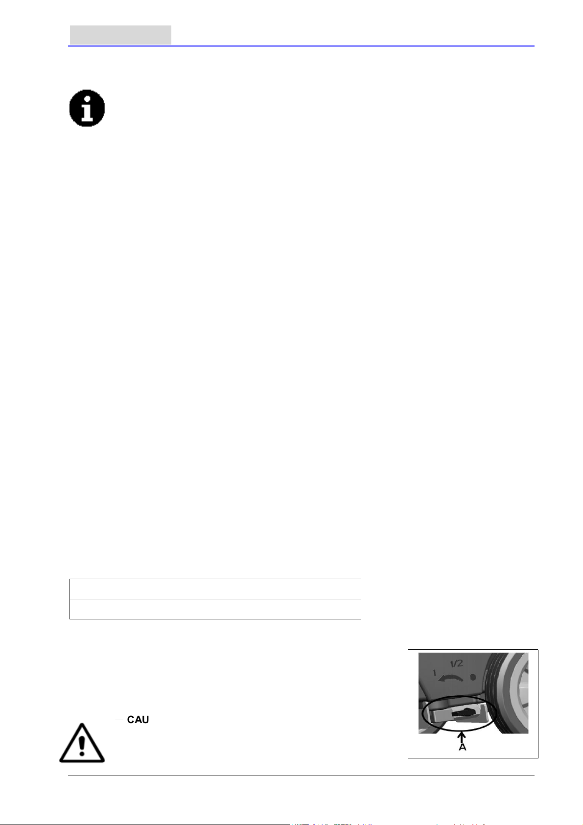
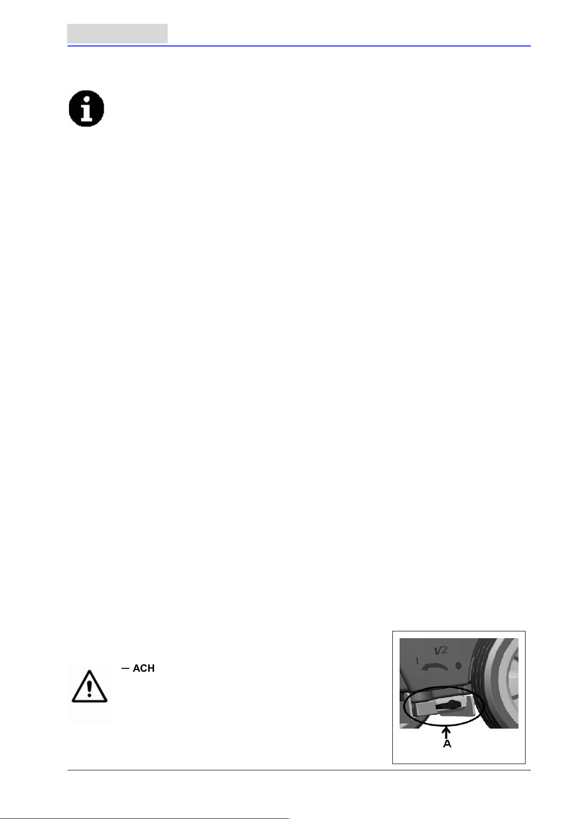
CAUTION
When unpacking and unloading, or during moving the
machine across ground with steps, please take care to
avoid hitting the on/off switch regulating the water flow,
Part A in the figure on the right.
2
Page 5
USER MANUAL
Check if the machine is equipped with the following items:
1. Technical documents
-
Scrubber User Manual
-
On-board Charger Manual (if equipped)
2. connector for Charger (if not equipped with on-board charger, it is on the specified external
charger)
ENGLISH
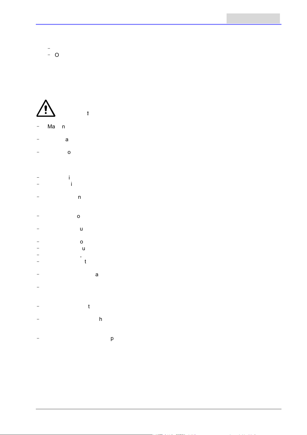
GENERAL SAFETY GUIDES
The following are special warnings and notices on potential damages (personnel and machine):
WARNING
-
Machine may only be operated under the guidance of this manual. Only accessories
approved by VIPER should be used.
-
This machine must be only used by duly trained or authorised personnel. Children or
inappropriate persons must not use this machine.
-
Under normal use, the battery may emit inflammable gas. The battery must be kept away
from radiating, illuminating, and burning items as well as sparks. When the machine is being
used, please ensure that the environment is well ventilated and is away from naked flames.
When charging, please do not smoke in the vicinity of the machine.
-
Please disconnect the battery prior to the performance of any maintenance/repair operations.
-
Before using the on-board charger, please ensure that the values of voltage and frequency as
indicated on the serial number sticker match those of the mains.
-
When working near electrical parts, please do not wear any jewelry. Please take all
precautionary measures to avoid the hair, jewelry, and loose fitting clothes from being caught
by any moving parts of the machine.
-
Please do not use this machine in particularly dirty areas. Do not wash the machine directly
with water. Do not let the machine come in touch with corrosive liquids.
-
The temperature for storage and for working environment of the machine must be between 0 -
400C.
-
The humidity of air must be between 30% - 105%.
-
Please do not use the machine on a slope with a gradient of more than 2%.
-
In case of fire, please use dry powder fire extinguishers. Do not use liquid fire extinguishers.
-
Particular attention should be paid when the machine is transported below 00 C. The water
tank and the water in the hoses may freeze and cause serious damages to the machine.
-
Use brushes and pads supplied with the machine and those specified in the User Manual.
Using other brushes or pads could reduce safety.
-
In case of machine malfunction, please make sure that it is not caused by lack of maintenance.
If it is caused by other conditions, please seek the assistance of authorised personnel or the
service center.
-
If it is confirmed that the spare parts must be replaced, please secure the genuine parts from
authorised dealers or agents.
-
In order to ensure the safe and proper operation of the machine, please let authorised
personnel or the service center perform the scheduled maintenance according to the
maintenance schedules in the related sections of the manual.
-
This machine must be properly disposed of because there may exist poisonous and
hazardous matters (batteries, etc.), and these matters must be disposed of by special centers
in accordance with related laws and regulations (please refer to machine disposal section).
!!!!
3
Page 6

ENGLISH
USER MANUAL
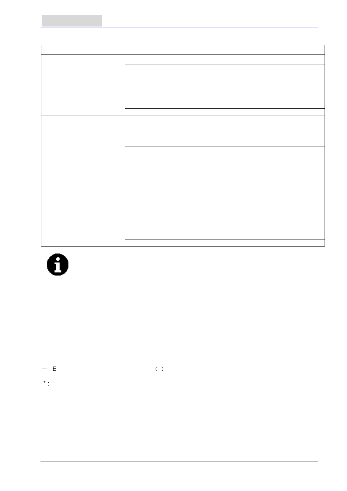
TECHNICAL DATA
Model AS430B AS510B
Machine Height 980mm
Solution tank capacity 40 litre
Recovery tank capacity 40 litre
Diameter of transport wheel 200mm
Diameter of guide wheel 76mm
Power of vacuum system motor 350w
Maximum gradient when working
Sound pressure level at workstation
Standard batteries (2×12V) 24V 85Ah AGM (2×12V) 24V 105Ah AGM
Battery compartment size (W x L x H) 340 x 330 x 260mm(Max)
Vacuum system circuit capacity
Cleaning width
Squeegee width
machine maximum length
Machine width without squeegee
Brush diameter
Weight with batteries and with empty tanks
Gross weight of the machine ready for use 152kg 168kg
Brush motor power
Brush speed
Brush /pad-holder Maximum pressure
Packing size (Lx W x H)
430mm 510mm
730mm 790mm
1060mm 1100mm
480mm 540mm
430mm 510mm
112kg 128kg
550W 560W
30kg (Max) 35kg(Max)
1200 x 610 x 1170mm
%
(Max)
2
70dB(A
1200 mm H
)
150rpm
±3dB(A)
2
O
MACHINE DESCRIPTION
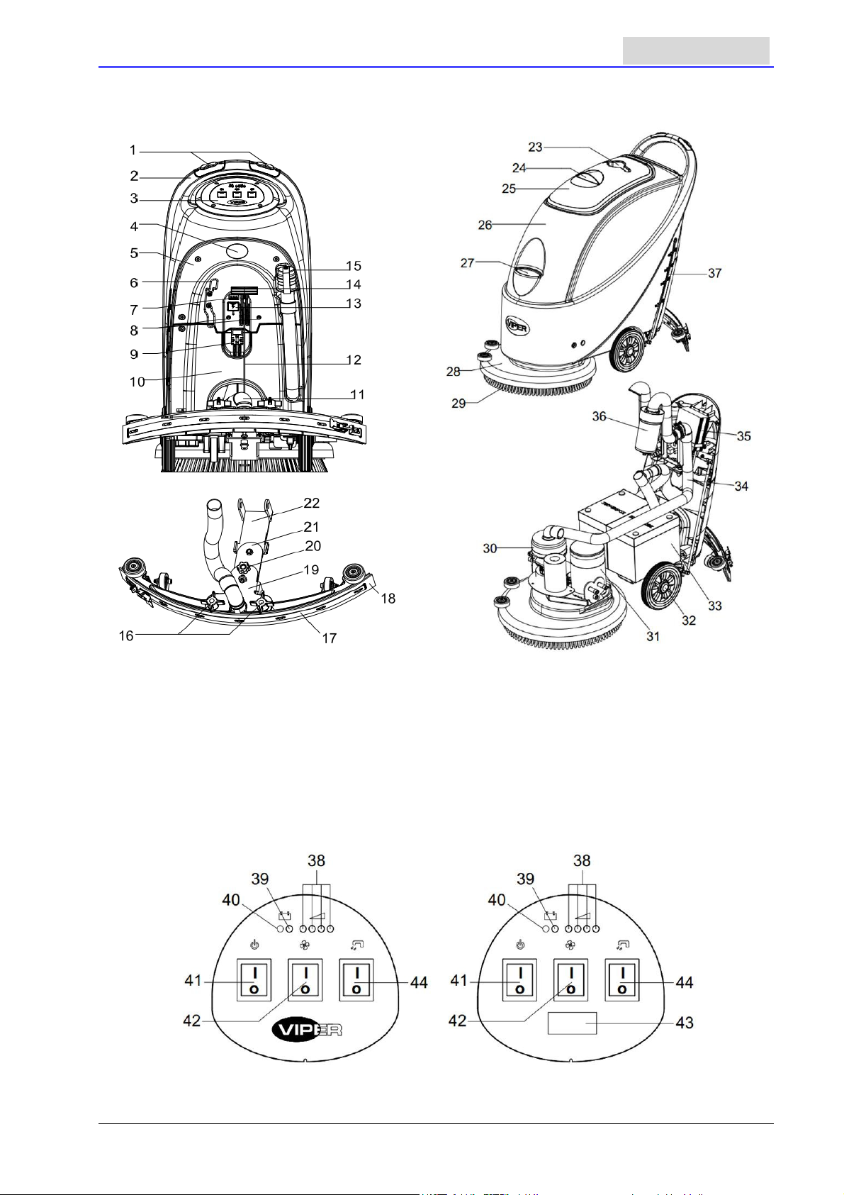
MACHINE STRUCTURE
1. Safety switch button 20. Squeegee adjusting handwheel
2. Handlebar 21. Squeegee rear support frame
3. Control panel 22. Squeegee front support frame
4. Serial number plate/Technical data
/ Conformity certification
5. Control cover 24. Recovery tank cover handle
6. Cable holder (*) 25. Recovery tank cover
7. Battery charging indication light 26. Tank body
8. Reset switch 27. Water inlet cover
9. Battery connector 28. Brush deck
10. Battery cover 29. Brush / pad-holder
11. Vacuum tube for waste 30. Vacuum system motor
12. Squeegee drawing cord 31. Brush motor
13. Battery connector safety cover 32. 8” wheel
14. Squeegee lifting handle 33. Battery
15. Draining hose 34. Vacuum tube
16. Squeegee fixed knob 35. Charger (*)
17. Squeegee clip 36. Float filter
18. Squeegee blade 37. Water level tube ( to indicate amount of water
19. Squeegee support frame
(*) applicable only to machines already installed with on-board charger (optional)
23. Cup holder
in Solution tank)
4
Page 7
FIGURES OF MACHINE STRUCTURE
USER MANUAL
ENGLISH
Figure 1
CONTROL PANEL (Figure2)
38. Battery charge indication light (green when saturated)
39. Battery exhausted indication light (red)
40. Battery exhausted indication light (red)
41. Power switch
42. Vacuum switch
43. Timer (optional, used to record working time of brush)
44. Solenoid valve switch for water spraying control
AS430B AS510B
Figure 2
5
Page 8
ENGLISH
USER MANUAL
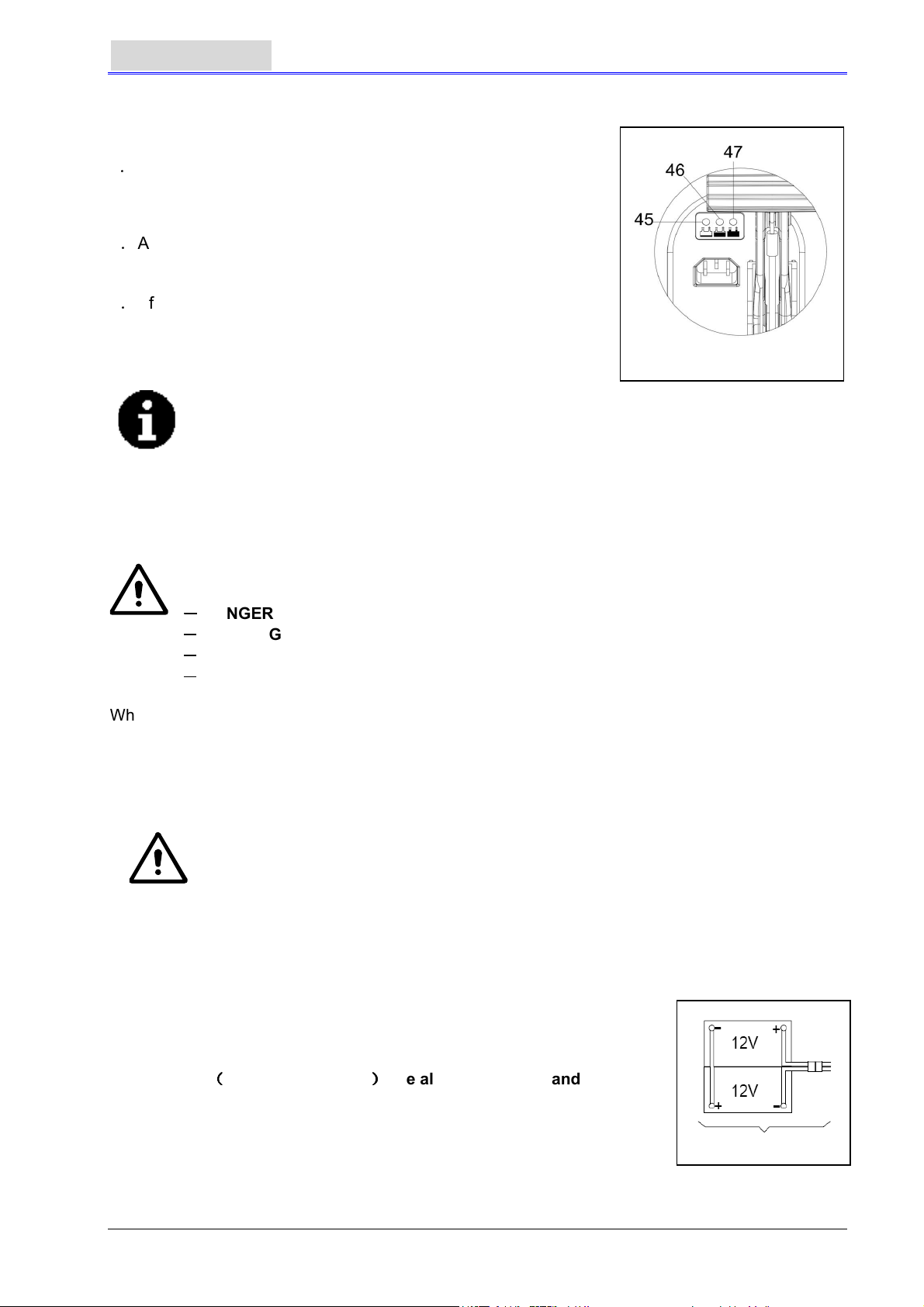
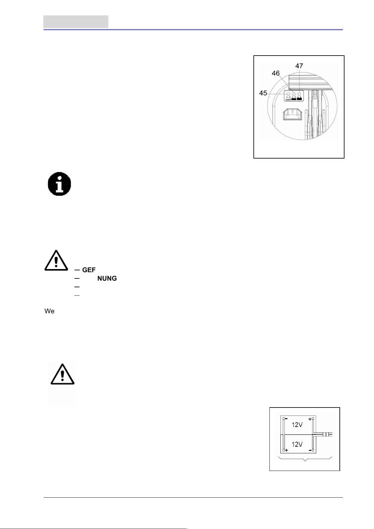
DISPLAY WINDOW OF CHARGER INDICATION LIGHT (Figure 3)
(Optional, applicable to models with built-in charger)
1. When charging starts, the red indication light of the charger
(45)flashes a few times and then steadies to become a
permanent red indication light, entering into the first stage of
charging;
2. After charging for a period of time, the red indication light of
the charger (45) will go out, A yellow indication light (46) will
light up permanently: entering the second stage of charging;
3. After charging for approximately 10 hours, the amber
indication light (46) will turn off, (47) The green indication light
will become permanently lit, indicating that the charge is full,
and charging has ended.
NOTE
1) During charging, If the yellow indication light flashes: the battery is not of the
type compatible to the charger, or the battery is not properly connected, or a
short circuit has taken place at the output terminal.
2) If the red indication light is flashing: a short circuit inside the charger. (For
details, please refer to the related sections in the charger instruction.)
Figure 3
GUIDE FOR USE
WARNING
On certain parts of the machine are pasted some indicative signs:
----
DANGER
When reading this manual, the operator must pay particular attentions to the symbols on these signs.
Under no circumstances shall these signs be covered. If they are damaged, please replace
immediately.
INSTALLING AND SETTING THE BATTERY OF THE NEW MACHINE
Please check if the battery is damaged before installing.
Be careful when touching the battery.
This machine needs two (2) 12V batteries. Please connect as shown
in Figure 4 on the right.
This machine can supply any of the following models:
a) Batteries
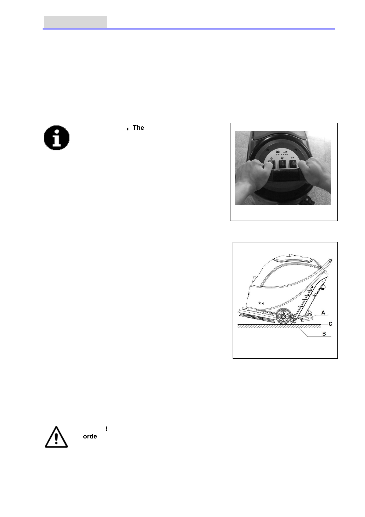
1. Check the battery. Through the connector (9) connect the battery to the
2. (Only applicable to AS430B and AS510B): Press down the on/off switch
If the amber or red light is on, it shows that the battery needs charging. (Please refer to the
----
WARNING
----
CAUTION
----
CONSULTATION
WARNING
If the battery is incorrectly installed or inaccurately connected, the electric
components of the machine may be seriously damaged. The battery may only be
installed by qualified personnel. According to the battery model number (WET or
GEL) being used, set the functional circuit board and on-board charger (optional).
Disconnect the battery connector and the on-board charger plug.
((((
WET or GEL/ AGM
used at any time.
machine.
(41). If the green light is on, it shows that the battery is ready for use.
section on maintenance for related procedures).
))))
are already installed and can be
Figure 4
6
Page 9
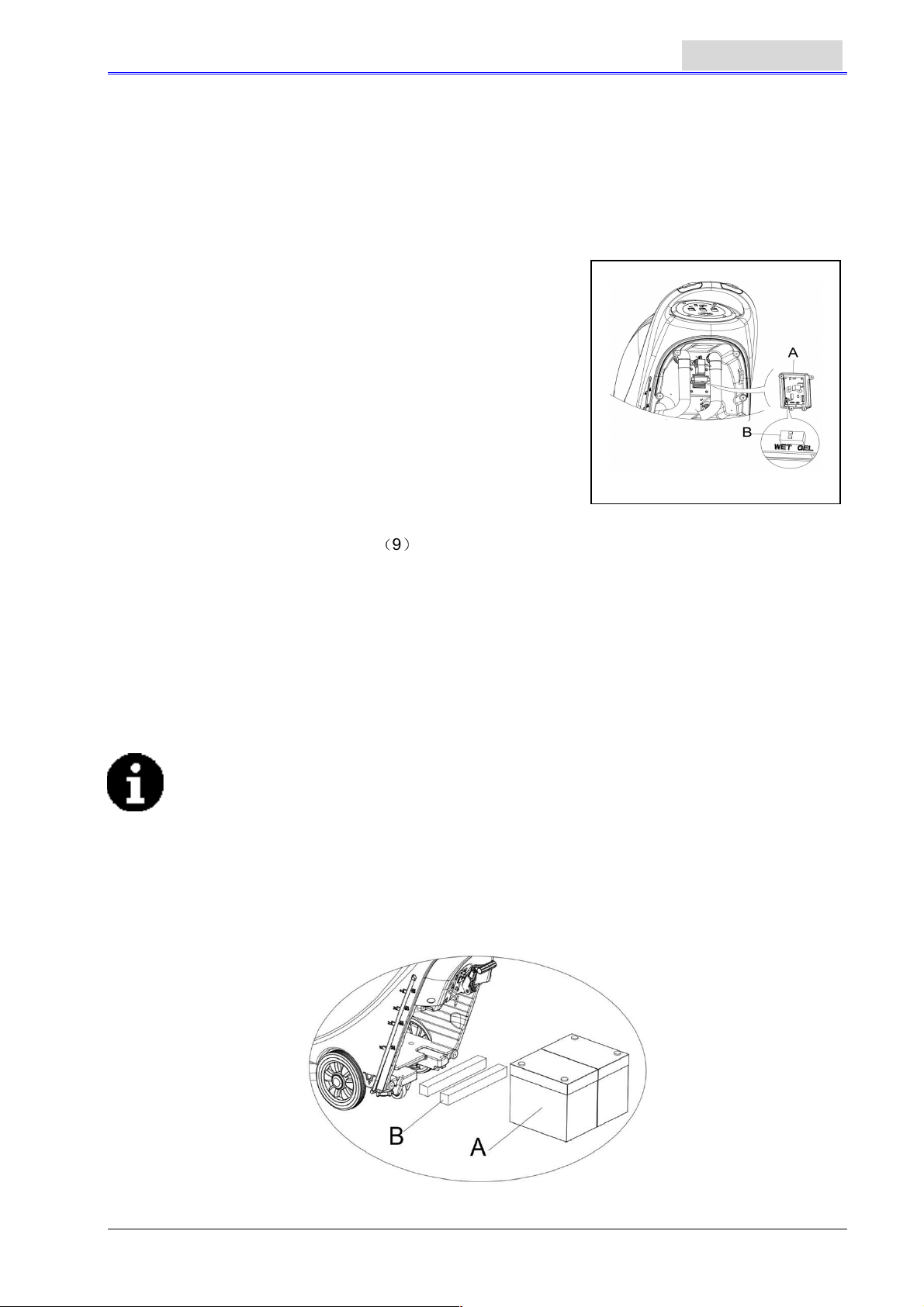
Figure 5
USER MANUAL
b) Without batteries
1. Purchase similar battery (refer to the section on technical parameters). Information on the
selection of battery may be obtained from qualified battery agents.
2. Set the machine and the on-board charger (if equipped) according to the type of batteries (WET
or GEL/AGM). Also read the following paragraph for the way to install the battery.
ENGLISH
INSTALLING BATTERY AND SETTING BATTERY TYPE((((WET OR GEL/AGM))))
According to the battery type(WET or GEL/AGM) set the electric circuit board on the on-board charger.
The procedures are as follows:
1. Make sure the connector of the battery is disconnected. If the
machine is based on “AGM” battery at time of ex-factory, go
directly to Step 8; otherwise, complete Steps 2, 3, and 4.
2. Take off draining hose (15)
3. If equipped with on-board charger, please take off the charge
wire from the reel.
4. Take off the control cover (5), and the screws of the battery
cover (10). Remove the screws on the PCB stand. The DIP
switch (B) for setting the battery model can be seen when
flipping over the PCB board. (See Figure 5)
5. Adjust the micro DIP switch (B) to the position of “WET”,
6. Complete Steps 3, 4 and 5 in reverse order.
Installing batteries
(9)
7. Disconnect the battery connector
8. Open the recovery tanks cover (25) and check if the recovery tank is empty or not; if not, empty it
through draining hose (15).
9. Unscrew the squeegee fixed knob (16), take off the connector connecting the vacuum tube for
waste (11) to the squeegee, and then take off the squeegee.
10. Unscrew the screws of the battery cover (10) and remove the cover.
11. 11. Unscrew the connector of the squeegee drawing cord (12) connecting to the squeegee
bracket (19), and hang the squeegee drawing cord upwards.
12. Hang draining hose (15) and the vacuum tube for waste (11) upwards.
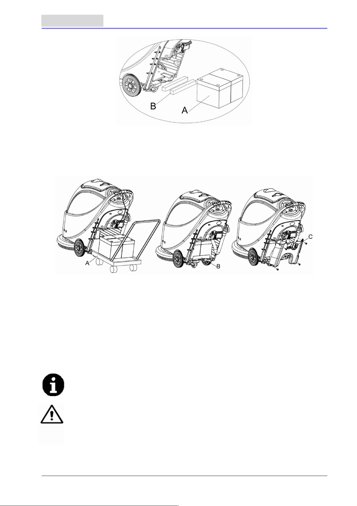
13. According to the size of the battery, push the fixation board in the battery box all the way inwards.
NOTE
The dimension of the battery must not exceed: H x W x H: 330mm x 170mm x 260mm.
According to the varying dimensions of batteries, the requirements for the selection of fixed
batteries are as follows:
1. For battery with length below 270mm, use 2 pieces of the fixation board (B, Figure 6)
and place them side by side inside the water tank battery;
2. For battery with length between 310mm-270mm, use 1 piece of the fixation board (B,
Figure 6) and place it in the water tank battery;
3. For battery with length between 330mm -310mm, there is no need for the fixation board
to fix the position.
.
Figure 6
7
Page 10
ENGLISH
14. Install the battery with specially made battery installation tools (A, Figure 7). After the battery is
installed, remove the battery installation tools, and install the battery fixation bracket (B, Figure 7).
USER MANUAL
15. Put the battery connector (C, Figure 7) through the hole on the top of the battery box cover, put
the draining hose through the right hole of the battery box cover, fix the battery box cover with 4
screws, and then install the squeegee drawing cord, draining hose, and the squeegee
successively.
Charging the battery
16. To charge the battery (refer to the steps stated in the maintenance section).
BEFORE MACHINE START-UP
Figure 7
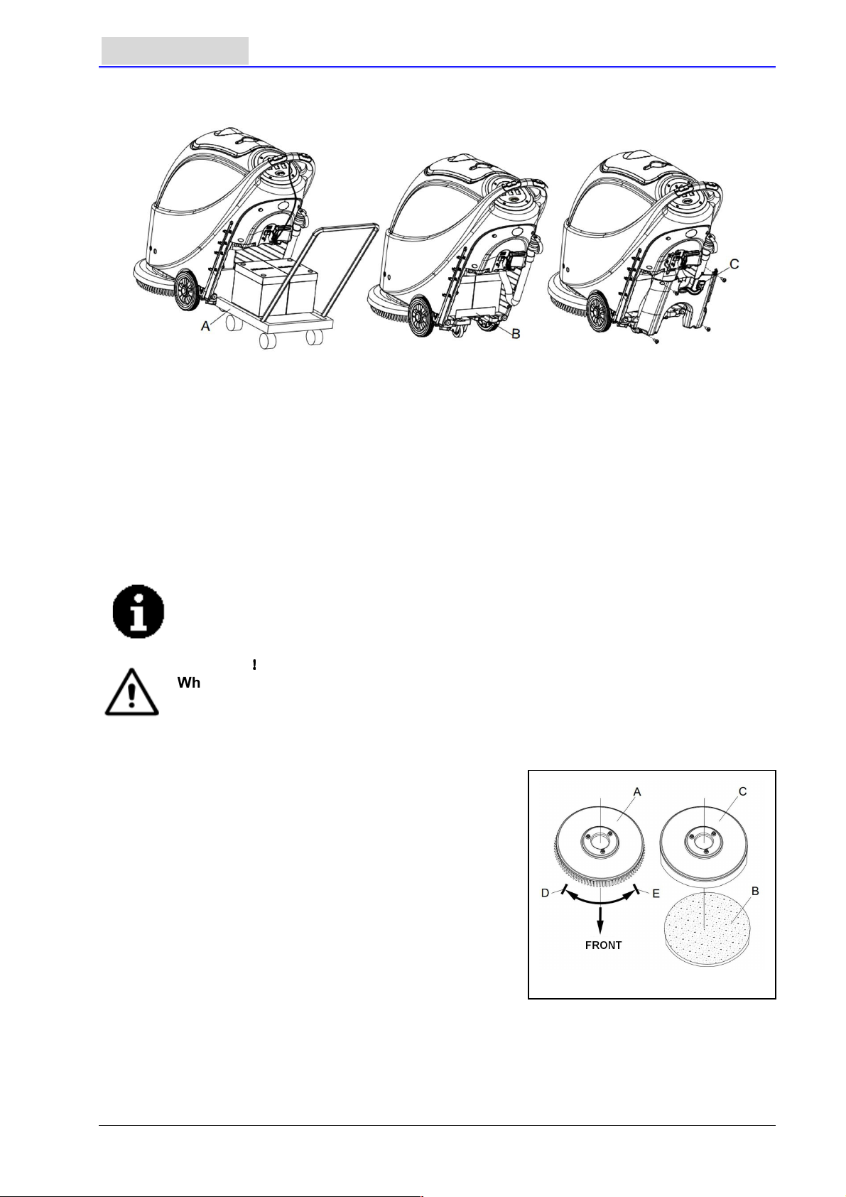
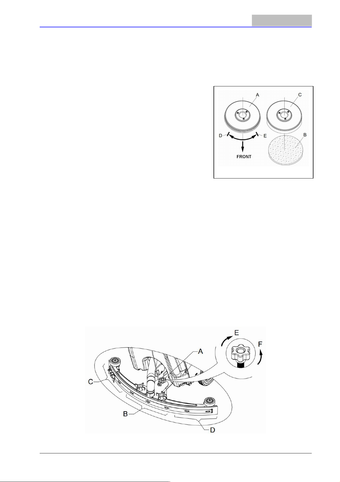
INSTALLING AND UNLOADING THE BRUSH / PAD-HOLDER
NOTE
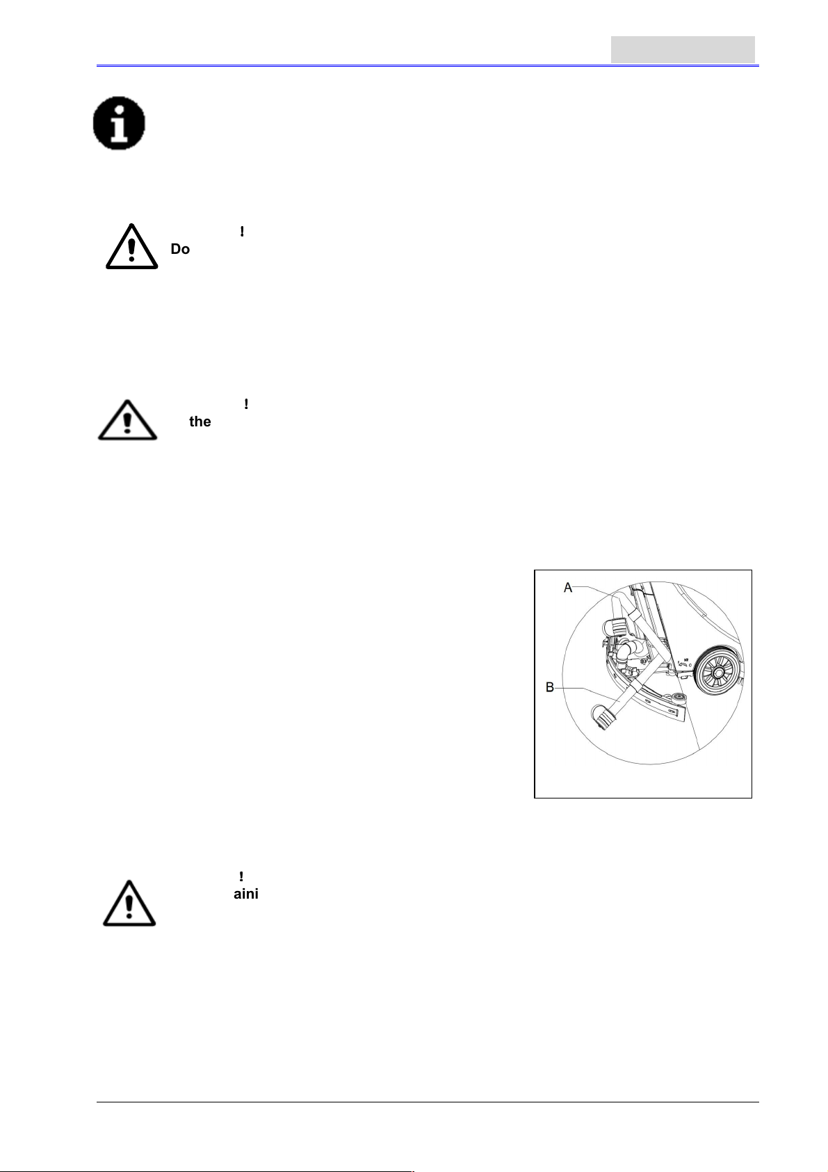
According to the type of floor to be cleaned, the machine may be installed with
brush (Figure8, A), or a pad-holder (Figure 8, B and C).
CAUTION
When manually installing or unloading the brush/pad-holder, first check if all the
switches are in the off position and lift the squeegee off the floor, only after which
can the brush or pad-holder be worked on. Furthermore, please put on protective
gloves to avoid being cut by fragments.
1. (Only applicable to AS430B and AS510B): make sure the
switch (41) is at the disconnecting (O) condition.
2. Press down the handlebar (2) to lift the tank body (26).
3. Put the brush (A) or the pad-holder (B – C) under the case.
4. Use the handlebar (2) to lower the tank body (26) to come
into contact with the brush or pad-holder.
5. To install the brush/pad-holder automatically, turn the
power switch (41) to the “I” position and press down the
safety switch (1). Gently push the machine forward so as
to allow the belt wheel at the bottom of the tank body to
align with the brush or pad-holder which can then be
installed. Then release the safety switch. If necessary,
repeat this procedure until the brush/pad-holder is installed.
6. If Step 5 above proves to be difficult, use the manual
method by following the arrow head (D) to install the brush/pad-holder (as shown in Figure 8).
7. To automatically unload the brush/pad-holder, turn the power switch (41) to the “O” position. Use
the hand to hold the handlebar, and press the machine downwards until the guide wheel touches
the floor and the brush/pad-holder hangs in the air. Turn the power switch (41) to the “I” position,
and press down the safety switch to let the brush or pad-holder turn until the brush/pad-holder
drops to the floor.
!!!!
Figure 8
8
Page 11
USER MANUAL
8. If Step No. 7 above proves to be difficult, use the manual method by turning the brush/pad-holder
in the direction opposite to the normal turning direction, and it can be taken off. (as shown in
Figure 8)
ENGLISH
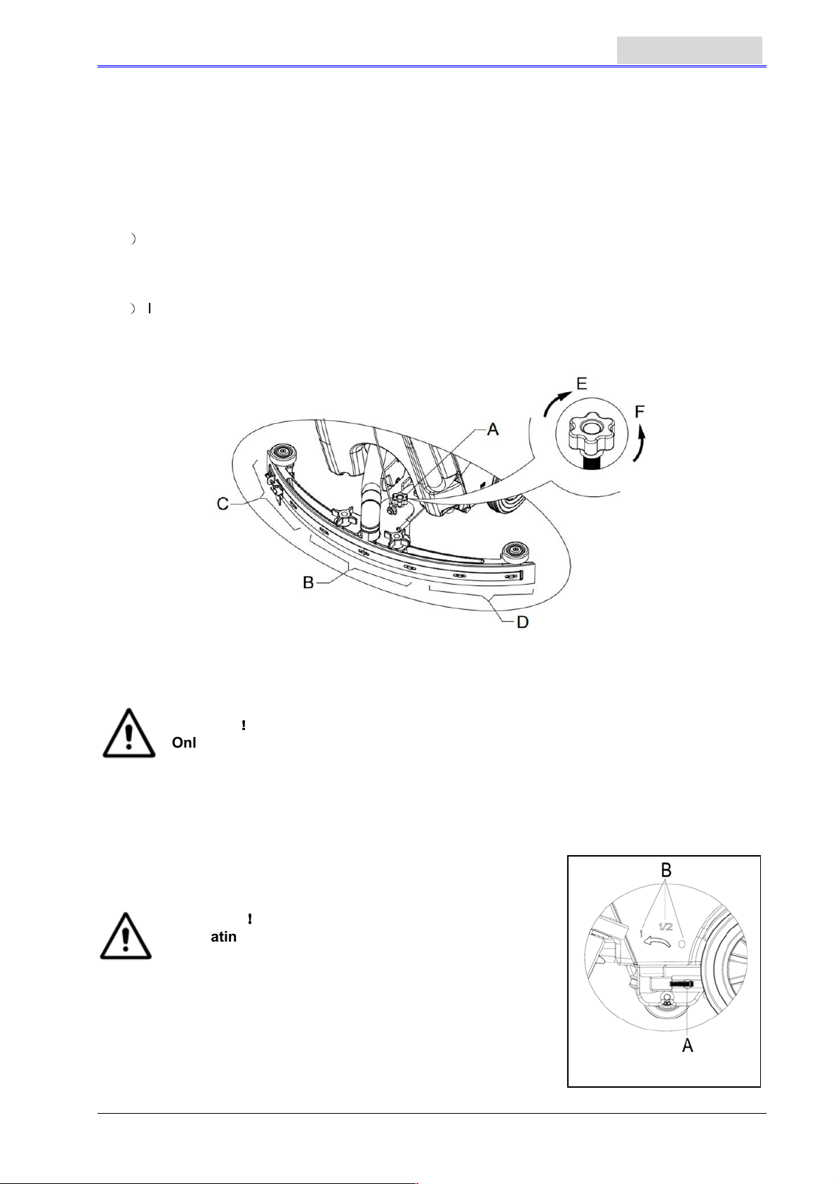
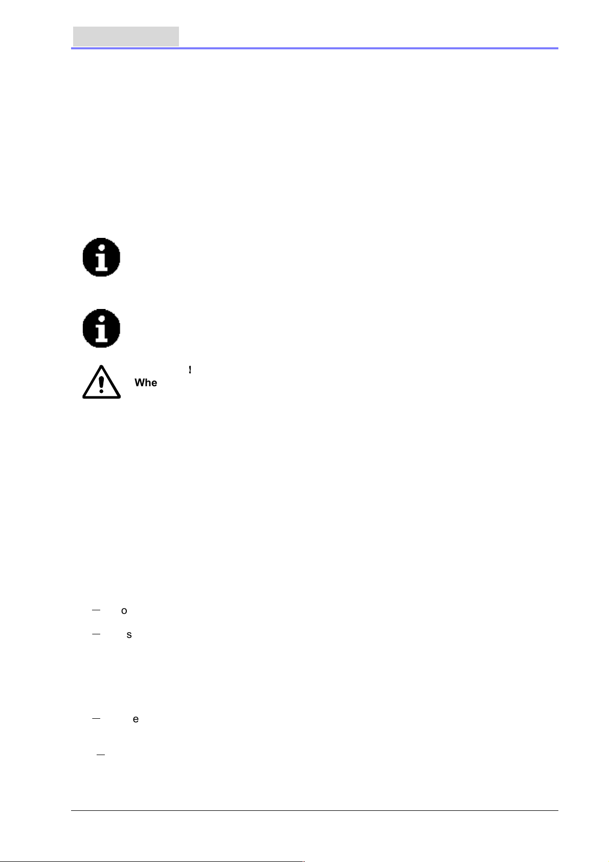
ADJUSTING THE BALANCE OF THE SQUEEGEE
9. Install the squeegee and turn it tight with the handle. Then connect the vacuum tube for waste to
the squeegee.
10. Adjust the squeegee through the adjusting handle (A) of the squeegee (see Figure 9).
1) If the mid-section of the rear squeegee strip, section B, has a gap with the floor or the
downward pressure is relatively light, adjust the handle in an anti-clockwise direction until the
whole length of the rear squeegee strip touches well with the floor. The front squeegee strip
should lightly touch the floor.
)
If the two ends of the rear squeegee strip, sections C and D, have a gap with the floor or the
2
downward pressure is relatively light, adjust the handle in a clockwise direction until the whole
length of the rear squeegee strip touches well with the floor. The front squeegee strip should
lightly touch the floor.
Figure 9
Solution tank filling
!!!!
CAUTION
Only low foam, nonflammable detergents may be used. These detergents must be
suitable for the use of scrubbers.
11. Open the water inlet cover (27) and add water to solution tank. Do not overfill the tank. Filling up
to near the edge of the filter holder of the water inlet will suffice. When preparing the cleaning
solutions, please follow the dilution rates supplied by the chemical manufacture and the water
temperature must not exceed 400 C.
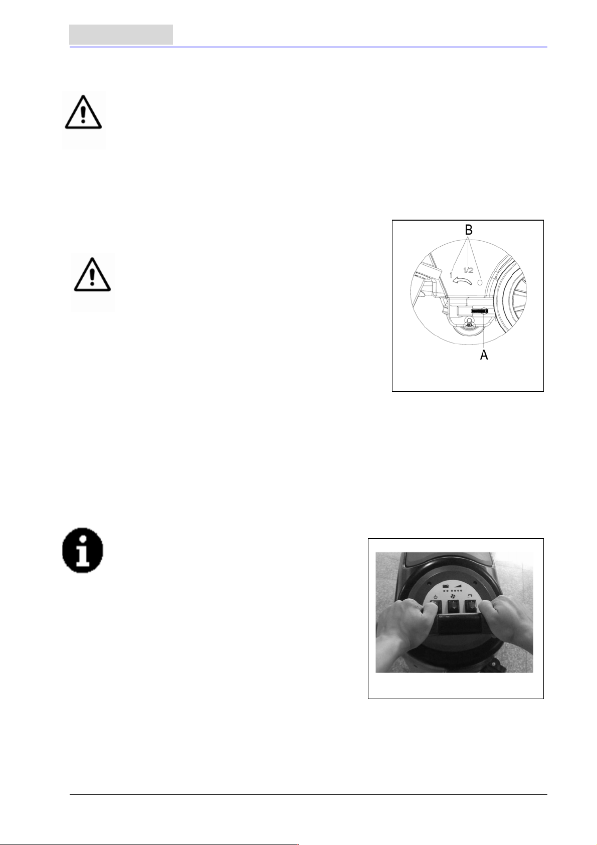
REGULATING THE VOLUME OF WATER FLOW
WARNING
Regulating the ball valve handle (A, Figure 10) must be
done under the condition when the power switch (41)
is in the “O” position.
12. The volume of the water flow may be adjusted through the ball
valve handle (A, Figure 10) according to the amount of water
practically required for scrubbing the floor.
!!!!
Figure 10
9
Page 12
ENGLISH
MACHINE START AND STOP
Starting the machine
1. Complete the preparatory steps as related above.
2. Press the power switch (41) to the “I” position.
3. Use the squeegee handle (41) to lower the squeegee.
4. Press the Vacuum pump switch (42) to the “I” position.
5. Press the water flow volume control switch (44) to the “I” position. (Work simultaneously with the
safety switch (1) to control the work of solenoid valve.)
6. Hold the safety switch (1) and push to move the machine. The brush (29) starts to rotate, and the
machine starts its cleaning job.
CONSULTATION
One of the characteristics of the machine is the
Installation of two safety switches on both sides
of handlebar. Each safety switch is capable of
controlling independently the operation of the
brush. In use, it facilitates the control of the
operation of the machine.
By experience, the method to move the machine
shown on right Figure 11 is more suitable, the
users feel more comfortable on hands, it
reduces work fatigue. So the users are
recommended to move the machine in this way
Turning off the machine
7. When you have finished using the machine, first unload the brush/pad-holder (refer to the steps
related in the section on brush/pad-holder installation and
unloading)
8. Release the safety switch (1) to turn off the brush/padholder and solenoid valve.
9. 9. Press the Vacuum pump switch (42) to the “O” position,
and the Vacuum pump will delay for 5 seconds before
stopping work.
10. 10. Press the water flow volume control switch (44) to the
“O” position to completely turn off the work of solenoid valve.
11. Press the power switch (41) to the “O” position.
12. Use the squeegee lifting handle (14) to lift the squeegee.
13. Grasp the handlebar (2) and gently tilt the machine
backward until the guide wheel (B) touches the floor. See
Figure 12.
MACHINE OPERATION (SCRUBBING AND DRYING)
USER MANUAL
::::
The way to push the machine
.
Figure 11
Figure 12
1. Start the machine according to the description above.
2. Hold the safety switch (1) (according to the way shown in Figure 11), push to move the machine,
and start the cleaning job.
3. If necessary, turn off the machine, and adjust the regulating handle of the squeegee. (Refer to
the steps for adjusting the balance of the squeegee)
4. If necessary, turn off the machine, and adjust the volume of water flow with the ball valve handle.
(Refer to the steps of adjusting volume of water flow.)
CAUTION
In order to avoid damaging the floor, when the machine stays in one place without
moving, please turn off the power switch (41).
Battery discharge during operation
5. It is only when the green warning light (38) is continuously lit that the power supply of the battery
is sufficient for the normal operation of the machine.
!!!!
10
Page 13
USER MANUAL
NOTE
When all the four green lights (38) turn on, it shows that the battery is fully charged.
When only the last green light (38) is on, and begins to flash, suggest charging the
battery, for the machine will stop automatically after a few minutes.
After the last green light (38) turns off, and the red light (39 and 40) begins to flash,
the machine will stop automatically after a few seconds. (Refer to the steps related in
the maintenance section).
CAUTION
Do not use the machine when the power supply of the battery is insufficient, so as
to avoid damaging the battery and shortening the life of the battery.
!!!!
ENGLISH
TANK EMPTYING
When recovery tank is full, a float in the automatic float turn-off device (36) will block the inlet
connecting to the vacuum pump. Through a sudden increase of noise from the vacuum pump, it can
be considered that the vacuum pump is already overloaded and an immediate draining of the
wastewater is needed.
CAUTION
If the vacuum pump is suddenly turned off (e.g. because the machine is suddenly
moved resulting in an activation of the float), and if a resumption of operation is
needed, please perform the following steps: press the power switch (41 and 42) to
turn off the power and the vacuum pump, and open the recovery tank cover (25) to
check if the float in the float filter has returned to the water surface. Then close
recovery tank cover (25), and press the power switch (41 and 42) to turn on the
power and the vacuum pump.
When the recovery tank is fully filled with wastewater, follow the following steps to drain it all.
Recovery tank emptying
1. Turn off the machine.
2. By using the squeegee handle (14), lift the squeegee.
3. Move the machine to a dedicated dump site.
4. Grasp the handlebar (2) and gently incline the machine
backward until the guide wheel touches the floor. (For
docking of the machine please refer to the procedures in the
stopping of the machine section.)
5. Take off the draining hose from the fixation clip, bend the top
end of draining hose (as shown in A, Figure 13), and then
open the cover of draining hose, lower draining hose to a low
level or on the ground to drain the water. Alternatively,
directly place draining hose to a low position or on the ground
to make the water outlet face downward (as show in B, Figure 13), and then twist open the water
draining lid to drain off the wastewater in the tank. After draining is completed, use pure water to
cleanse the inside of recovery tank.
CAUTION
When draining the wastewater, the vacuum tube for waste must be folded or
lowered to a lower position (as shown in Figure 13 A or B), and then open the lid of
the vacuum tube for waste to drain the water. Do not make the outlet of the vacuum
tube for waste face upward to drain the water vertically. This is to avoid wastewater
spilling onto the operator.
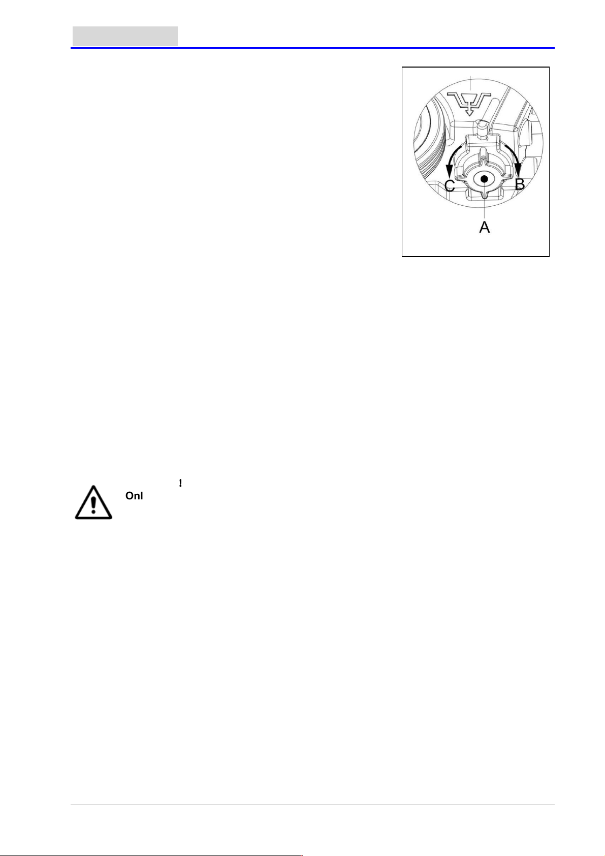
Solution tank emptying
6. Complete Steps 1 to 4.
7. As shown in Figure 14, turn open the lid of Solution tank (A) anticlockwise along direction C, and
drain Solution tank completely. Use pure water to cleanse the inside of Solution tank. When work
is completed, turn tight the lid of Solution tank (A) clockwise in direction B.
!!!!
!!!!
Figure 13
11
Page 14
ENGLISH
USER MANUAL
AFTER USING THE MACHINE
When work is done and before leaving the machine, completes the
following steps:
1. Follow the procedure as described in aforementioned section
about installing and unloading the brush/pad-holder, and take
off the brush/pad-holder.
2. Following the procedures described in related sections, drain
the water completely in Solution tank and recovery tank.
3. Complete the daily maintenance procedures (refer to the
section on maintenance).
4. Store the machine, including the brush/pad-holder and
squeegee, in a clean and dry place. The squeegee should be
lifted or taken off.
PERIODS OF INACTIVITY
If the machine is not to be used for more than 30 days, please treat
it in the following way:
1. Complete the necessary procedure that should be followed after the machine is used.
2. Disconnect the connector (9) connecting the battery and the machine.
3. In order not to damage the battery, and if the machine is not to be used for more than 3 months,
please charge the battery once every 3 months.
Figure 14
USING FOR THE FIRST TIME
After using for the first 9 hours, please check all parts to make sure nothing has become loose or
damaged during operation, and check if there are any visible damages or leakage.
MAINTENANCE AND CARE
The service life and the maximum operation safety of the machine are assured by proper and timely
maintenance and care.
The following table provides a general maintenance plan for the machine. The time intervals of
maintenance are determined to a large extent by the working conditions of the machine. These time
intervals should be formulated by the personnel responsible for the maintenance.
WARNING
Only after the power of the machine is turned off and the connection between the
machine and the battery is disconnected should these procedures be performed.
Before proceeding with any of the maintenance procedures, please study carefully
the related safety sections.
All maintenance in the plan or all additional maintenance must be done by qualified personnel or
authorised service centers.
This manual only relates the simplest and the most common maintenance procedures.
For any maintenance procedures other than those stated in this table of planned maintenance, please
refer to the maintenance manual of the service center.
!!!!
12
Page 15
USER MANUAL
ENGLISH
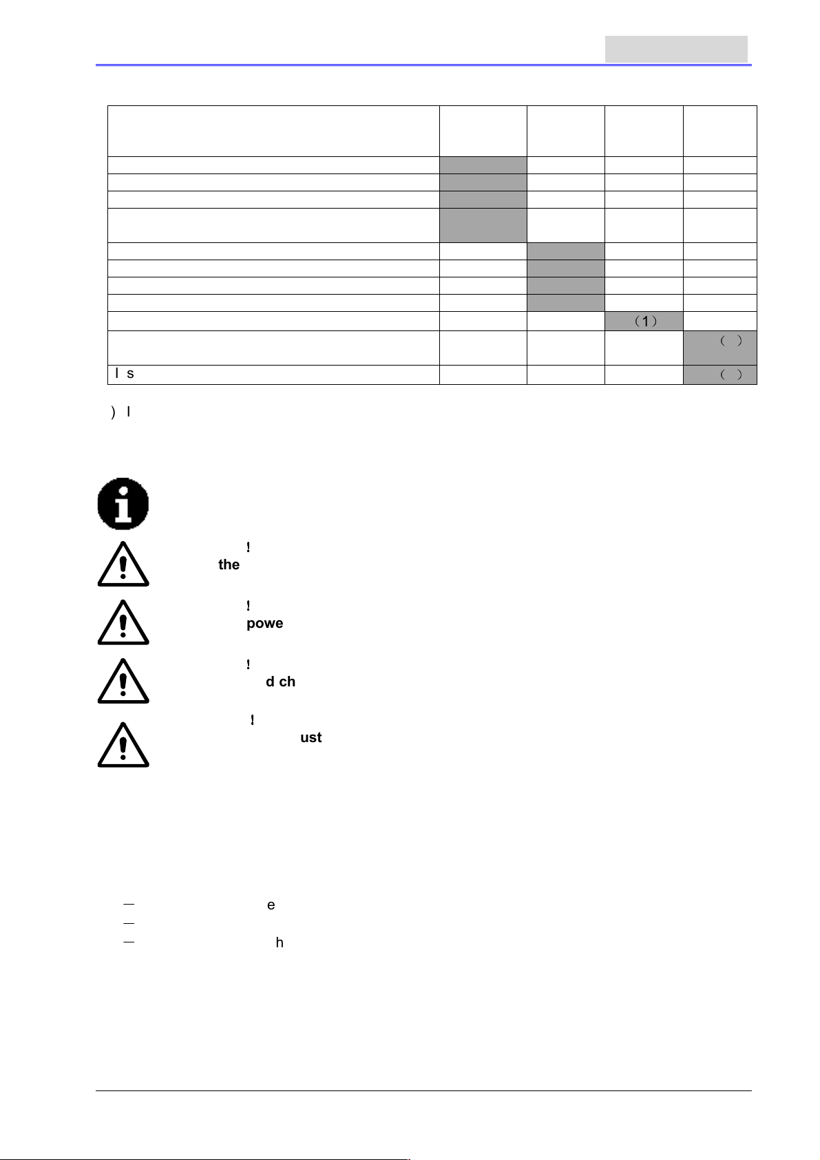
SCHEDULED MAINTENANCE TABLE
Procedure
Charge battery
Clean squeegee
Clean brush/pad-holder
Clean water tank and float filter, inspect the
sealing strips of the water tank
Inspect and change the squeegee strip
Clean Solution filter
Clean Vacuum pump filter
Inspect liquid level of WET battery
Inspect tightness of nuts and bolts
Inspect or change motor carbon brush of
brush/pad-holder
Inspect or change carbon brush of Vacuum pump
(1) It should be done 9 hours after the machine starts working.
(2) These maintenance procedures must be done by an authorized VIPER Service Center.
Daily,
Machine
after use
Weekly Every
6 months
(1)
BATTERY CHARGING
NOTE
It is time to charge the battery when the amber or red warning light is lit up, or
every time when work is done.
CAUTION
Keep the battery in a fully charged condition in order to extend the service life of
the battery.
!!!!
Annually
(2)
(2)
CAUTION
Once the power of the battery becomes insufficient, the battery must be charged
as soon as possible. Please check the charger at least once a week.
CAUTION
If an on-board charger is not equipped, please select a suitable external charger to
charge the battery.
WARNING
Particular care must be taken when charging the battery because there may be
leakage of acid during the charging process. Battery acid is corrosive. If skin or
1. Open the lid of recovery tank (25) and observe if recovery tank is empty or not. If it is not empty,
empty it through draining hose. (15).
2. Move the machine to a specified charging area.
3. Press the power switch (41) to the “O” position to turn off the machine.
4. Only applicable to WET water-addition battery
- Check the level of electrolyte inside the battery. If necessary, fill it up through the lid.
- Keep all lids open.
- If necessary, clean the top surface of the battery.
5. Select one of the following procedures to charge the battery according to the model of battery
being used.
To charge a battery with an external charger
6. Check, according to the related manual, if the external charger is appropriate. The output voltage
must be DC 24V.
7. Connect the battery connector to the external connector, and connect the external connector to
the mains.
the eye accidentally comes into contact, please flush with plenty of water and see a
doctor.
!!!!
!!!!
!!!!
13
Page 16
ENGLISH
8. When charging is complete, connect the charging connector of the battery to the machine.
To charge a battery with an on-board charger (optional)
9. Take off the rubber lid at the end of the battery charging connector.
10. Connect the end of the battery charging connector with the mains with a charge connecting wire.
(Please note whether the input voltage of on-board charger is 220V – 240V and the output voltage
24V and frequency meet the requirements.) When the charger is connected to the mains, all
other functions will be cut off automatically. If the red warning light on the on-board charger
continues to light, it shows that the charger is charging the battery.
11. When the green warning light (47) is on, it shows that the battery charging process is complete.
12. When charging is complete, take off the connecting wire from the end of the battery charging
connector and the power supply, and put on the rubber lid.
13. Disconnect the charger wire from the power supply, and wind the wire on the reel (6).
NOTE
If more information on on-board charger (35) is needed, please refer to related
manual.
USER MANUAL
SQUEEGEE CLEANING
NOTE
In order to maintain the optimal effect of water Vacuum, the squeegee must be
kept clean, and the squeegee strip must remain in a good condition.
CAUTION
When cleaning the squeegee, it is recommended to put on protective gloves
because the squeegee may contain sharp fragments.
1. Move the machine to a flat and smooth surface.
2. Press the power switch (41) to the “O” position to turn off the machine.
3. Unscrew the fixed handle (16) of the squeegee; take off the connector connecting the Recovery
Vacuum tube of the squeegee, and take off the squeegee.
4. Use the squeegee lifting handle (14) to lift the squeegee support frame.
5. Clean the squeegee (Figure 15). Clean in particular the groove (A, Figure 15) and the dirt and
fragments on the Vacuum tube. Check if the front squeegee blade (C) and the rear squeegee
blade (D) are intact, and if there are broken edges and cracks. Change them if necessary (refer
to the steps in the following section).
6. Re-install the squeegee in the reverse order of the above.
!!!!
SQUEEGEE BLADE CHECK AND REPLACEMENT
1. Following the methods related in the previous section clean the squeegee (Figure 15)
2. Check the edge (E, Figure 15) of the front squeegee blade and the edge (F) of the rear squeegee
blade (D). On the whole length, they should be on the same level. Otherwise, adjust their heights
through the following procedure.
-
Loosen the clip (G) to let the rear squeegee blade (D) separate from the bracket (M) for the
adjustment of the position of the squeegee. After the adjustment, lock the clip once again.
-
Loosen the screw on the handle (I) to adjust the front squeegee blade (C); tighten the handle
screw after adjustment.
3. Check if the front squeegee blade (C) and the rear squeegee blade (D) is intact and if there are
broken edges and cracks. If necessary, change them according to the following ways. Check the
front edge of the rear squeegee blade (J) whether it has been worn. If worn, it can be installed
upside down (the top edge is required to be intact). If the top edge is also worn, change it by
following the procedure below:
-
Loosen the clip (G) to let the pressure blade separate from the bracket (M), take off the clip
bar (K), and then change or turn the rear squeegee blade (D) upside down. Re-install the rear
squeegee blade in the reverse order of taking it off.
- Loosen the handle screw (I) and take off the front clip bar (L), and then change the front
squeegee (C).
Re-install the front squeegee blade in the reverse order of taking it off.
After changing the squeegee blade (or installing upside down), adjust the level of the front and
rear squeegee blades in the procedures as described above.
14
Page 17
USER MANUAL
4. Connect the Vacuum tube (11) to the squeegee.
5. Install the squeegee and use the knob (16) to tighten it, and then connect the Vacuum tube to the
squeegee.
6. If necessary, adjust the squeegee through the adjusting handwheel (20) (refer to the procedures
for adjusting the balance of the squeegee).
ENGLISH
Figure 15
BRUSH/POLISHING PAD CLEANING
CAUTION
When cleaning the brush/pad-holder, the wearing of protective gloves is
recommended because they may contain sharp fragments.
1. In the way as related in previous sections, take off the brush/pad-holder.
2. With the use of water and detergents, clean the brush/pad-holder.
3. Check the completeness and wearing condition of the bristles on the brush and, if necessary,
change the brush.
4. Check the wearing condition of the pad-holder and, if necessary, change the pad-holder.
!!!!
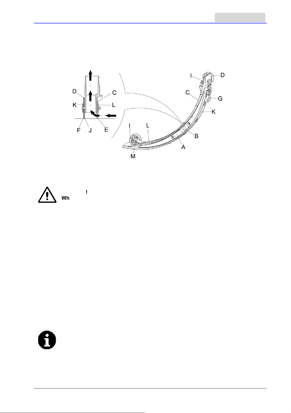
WATER TANK AND FLOAT FILTER MESH CLEANING
1. Move the machine to a dedicated dumping site.
2. Press the power switch (41) to the position “O” to turn off the machine.
3. Open recovery tank lid (A, Figure 16), and take off the float device (36) from recovery tank.
4. Use pure water to clean recovery tank lid (A), the tank (B and C), and the float filter support frame
(E). Through the Recovery tube (15), drain all the water from the water tank.
5. If necessary, following the symbols “Open” and “Close” as shown in Figure 16, open the bottom
lid (F) of the float filter and clean the float (D), float filter support frame (E), and the filter sponge (I).
After cleaning, fix the float onto the float filter support frame (E), and then align the mark groove (L)
of the bottom lid (F) of the float filter with the mark groove (L) of the float filter support frame (E).
Turn the bottom lid (F) of the float filter tight, and fix the filter sponge (I) onto the float filter support
frame (E), and then onto the Vacuum tube (M).
6. Check the soundness of the sealing ring (G) of the water tank lid.
NOTE
The sealing strip (G) of the water tank makes the water tank create a vacuum. It
must be completely sealed to be able to effectively suck the wastewater from the
floor.
If necessary, the sealing strip of the water tank (G) may be taken out from the groove (H) and
changed. When assembling a new water tank sealing strip, as shown in Figure 16 below, install
the connector to the middle section of the rear part.
7. Check if the receiving surface of the sealing strip (G) is intact and seals adequately.
8. Close recovery tank lid (A).
15
Page 18
ENGLISH
USER MANUAL
Figure 16
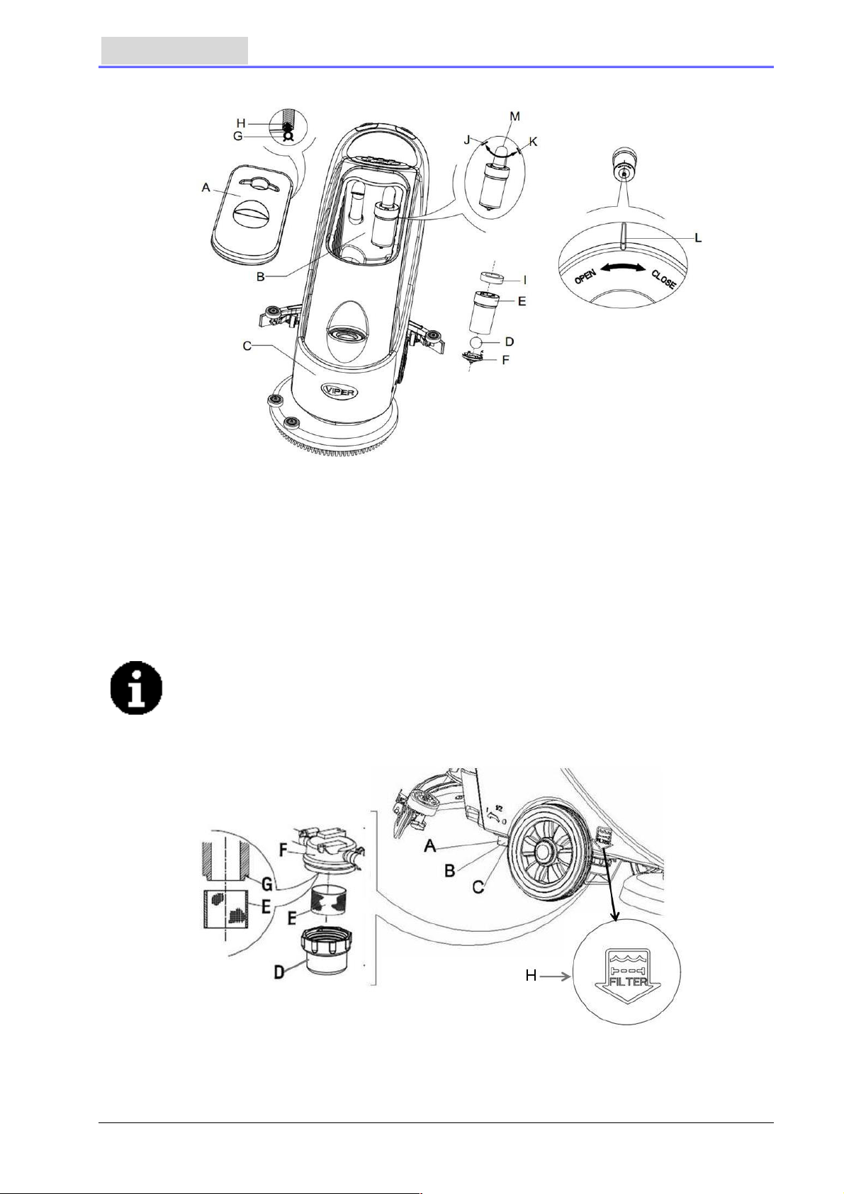
SOLUTION FILTER CLEANING
1. Drain all the water from Solution tank in the way as introduced in related sections.
2. Move the machine to a flat and smooth ground.
3. Press the power switch (41) to the “O” position to turn off the machine.
4. Turn off the draining ball valve (A, Figure 17) (located at the bottom of the machine, behind the
wheels). Position B ball valve open, and position C ball valve closed.
5. Take off the transparent lid (D), and then take off the filter (E), and install them onto the filter box
(F) after cleaning.
NOTE
The filter (E) must be accurately installed onto the position of the projection (G).
6. Open the draining ball valve (A).
Filter Mesh Mark
Figure 17
16
Page 19
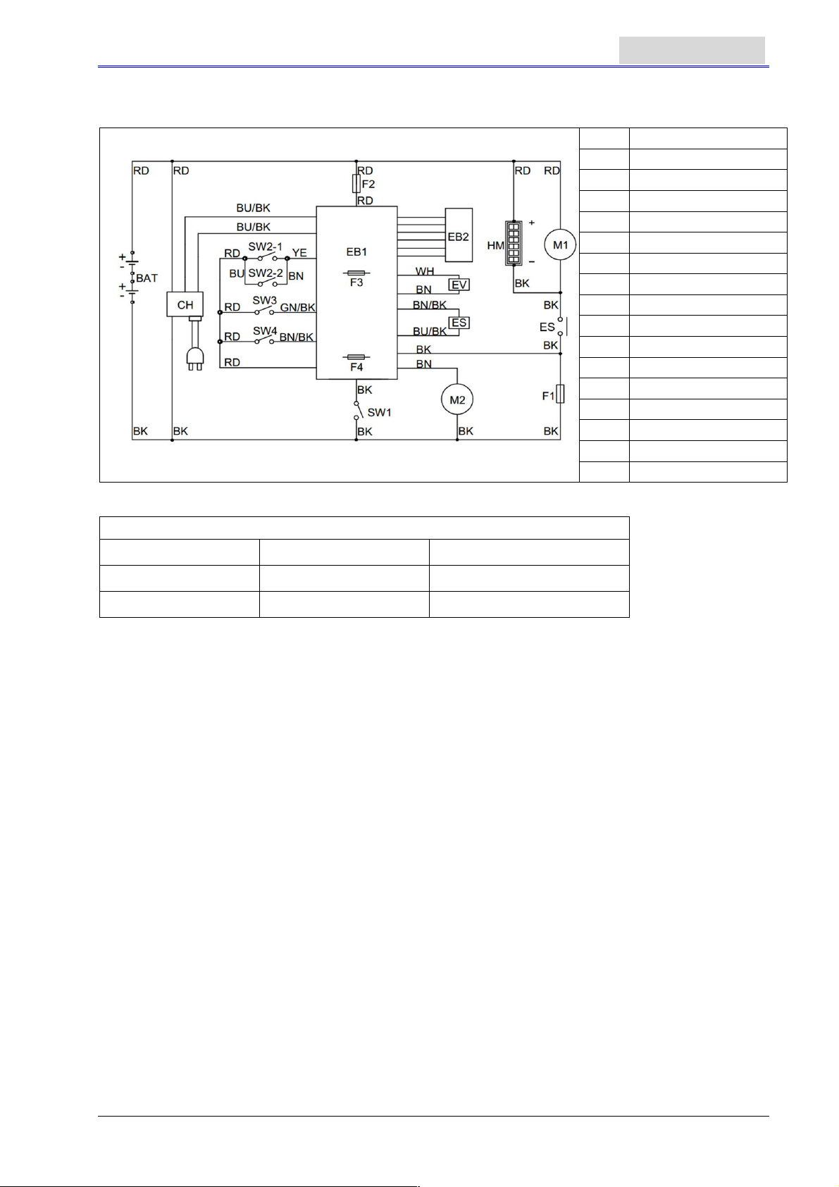
CIRCUIT FIGURE OF AS430B AND AS510B
COLORS CODES
USER MANUAL
BAT
CH
EB1
EB2
ES
EV
F1
F2
F3
F4
M1
M2
SW1
SW2
SW3
SW4
HM
ENGLISH
Battery
Charger
Control circuit board
LED board
Contactor
Solenoid valve
Brush motor fuse
Vacuum motor fuse
Control circuit board fuse
Solenoid valve fuse
Brush motor
Vacuum motor
Power switch
Brush motor switch
Vacuum motor switch
Solenoid valve switch
Timer (Only for AS510B)
RD: Red BN: Brown BU/BK : Blue /Black
BU: Blue YE: Yellow GN/BK: Green/Black
BK: Black WH: White BN/BK: Brown/Black
17
Page 20
ENGLISH
TROUBLESHOOTING
Breakdown Probable Causes Remedies
Machine not working:
Indication light not on
Warning light (39 and 40)
flashing
Brush not working
Vacuum motor not working Vacuum fuse trip off Reset
Inadequate Vacuum
Pure water supply to the brush
inadequate
USER MANUAL
Battery connector (9) not connected. Connect the battery connector
Battery power already exhausted Charge the battery
Brush motor overloaded
Other matters jam the rotating of the
brush
Brush fuse trip off Reset
Belt slipping Check belt, adjust tension pulley
Wastewater tank is full. Drain the water tank
Vacuum tube for waste and squeegee
not properly connected
Float filter blocked or inlet blocked
Squeegee dirty or squeegee blade worn
and damaged
Recovery tank lid not properly turned
on, or the sealing strip of the water tank
damaged
Filter dirty. Clean the filter
Change to a soft brush to adapt to
the floor being cleaned
Clear up the brush
Connect the Vacuum tube for waste
and the squeegee
Clean the float filter, check the float
ball
Clean and check the squeegee
Refit on the lid properly, or change
the water tank sealing strip
Squeegee leaving marks
Debris like fragments under the
squeegee blade
Squeegee blade already worn, cracked,
brittle.
Balance of squeegee not adjusted Adjust the balance
Remove the fragments
Change the squeegee blade
NOTE
If the machine is installed with the optional on-board charger, and when the onboard charger is defective, the machine cannot be operated.
If the on-board charger is defective, please contact the authorised maintenance
center.
To find out more information, please refer to the maintenance manual (available at
any maintenance center of VIPER)
MACHINE DISPOSAL
Use qualified crushing machine to destroy this machine.
Before destroying this machine, please take away and segregate the following materials which,
according to related laws and regulations, must be properly processed.
-
Battery
-
Brush/pad-holder
-
Plastic hoses and plastic components
-
Electrical and electronic components(*)
(*): Please contact the nearest VIPER Center (especially when scrapping of electrical and electronic
components is required).
18
Page 21

BEDIENUNGSANLEITUNG
DEUTSCH
INHALTSVERZEİCHNİS
EINLEITUNG ........................................................................................................................................... 20
INHALT ............................................................................................................................................ 20
ZWECK ............................................................................................................................................ 20
ERSATZTEILE UND WARTUNG ..................................................................................................... 20
ÄNDERUNGEN UND VERBESSERUNGEN .................................................................................. 20
ANWENDUNGSBEREICH ............................................................................................................... 20
AUSPACKEN/TRANSPORT ............................................................................................................ 20
ALLGEMEINE SICHERHEITSHINWEISE ....................................................................................... 21
TECHNISCHE DATEN ..................................................................................................................... 22
GERÄTEBESCHREIBUNG .................................................................................................................... 22
AUFBAU DES GERÄTS .................................................................................................................. 22
ÜBERBLICK ÜBER DAS BEDIENFELD ......................................................................................... 23
ANZEIGEFENSTER DER BATTERIELADUNGSANZEIGE ............................................................ 24
BEDIENUNGSANLEITUNG ................................................................................................................... 24
BATTERIEINSTALLATION UND -EINSTELLUNG DES NEUEN GERÄTS .................................... 24
BATTERIEINSTALLATION UND EINSTELLUNG DES BATTERIETYPS (WET ODER GEL/AGM)25
VOR INBETRIEBNAHME DES GERÄTS ........................................................................................ 26
MONTIEREN UND ENTFERNEN DER BÜRSTEN/PAD-HALTERUNG ......................................... 26
EINSTELLEN DER ABSTREIFERPOSITION ................................................................................. 27
REGULIERUNG DES WASSERDURCHFLUSSES ........................................................................ 28
START UND STOPP DES GERÄTS ............................................................................................... 28
EINSATZ DES GERÄTS (SCHEUERN UND TROCKNEN) ............................................................ 29
TANK ENTLEEREN ......................................................................................................................... 29
NACH DEM EINSATZ DES GERÄTS.............................................................................................. 30
STILLSTANDSZEITEN .................................................................................................................... 31
VOR DER ERSTEN VERWENDUNG ............................................................................................. 31
WARTUNG UND PFLEGE ...................................................................................................................... 31
TABELLE DER PLANMÄSSIGEN WARTUNGSARBEITEN ........................................................... 31
AUFLADEN DER BATTERIE ........................................................................................................... 32
REINIGEN DES ABSTREIFERS ..................................................................................................... 33
ÜBERPRÜFEN UND AUSTAUSCHEN DES ABSTREIFERBANDS ............................................... 33
REINIGEN VON BÜRSTE/POLIERPAD .......................................................................................... 34
REINIGEN DES SCHMUTZWASSERTANKS UND DES SCHWIMMFILTERSIEBS ..................... 34
REINIGEN DES FRISCHWASSERTANKS ..................................................................................... 35
SCHALTKREISDIAGRAMM VON AS430B UND AS510B .............................................................. 36
FEHLERBEHEBUNG ............................................................................................................................. 37
GERÄTEENTSORGUNG ........................................................................................................................ 37
19
Page 22
DEUTSCH
BEDIENUNGSANLEITUNG
EINLEITUNG
HINWEIS
Die Zahlen in Klammern beziehen sich auf die im Abschnitt "Beschreibung des
Geräts" dargestellten Komponenten.
INHALT DER BEDIENUNGSANLEITUNG
Dieses Handbuch dient dazu, den Anwender mit den notwendigen Informationen auszurüsten, um
dieses Gerät richtig und sicher nutzen zu können. Die Informationen beinhalten die technischen
Daten, Sicherheit, Betrieb, Lagerung, Wartung und Entsorgung des Geräts. Der Anwender und
Techniker mit entsprechenden Qualifikationen muss diese Anleitung sorgfältig vor Beginn der
Anwendung und Wartung dieses Geräts durchlesen. Setzen Sie sich bitte mit VIPER in Verbindung,
wenn Sie Anfragen hinsichtlich der Erklärungen in diesem Handbuch haben oder wenn weitere
Informationen benötigt werden.
ZWECK
Die Absicht dieser Bedienungsanleitung ist es, dem Anwender und qualifizierten Technikern zu
ermöglichen, die Wartung dieses Geräts durchzuführen.
Der Anwender sollte diese Tätigkeiten nicht durchführen, sie sollten nur von Technikern durchgeführt
werden. VIPER ist nicht verantwortlich für Schäden, die durch die Verletzung dieser Regel verursacht
werden.
ERSATZTEILE UND WARTUNG
Alle notwendigen Betriebs-, Wartungs- und Reparaturarbeiten müssen von qualifiziertem Personal
oder durch die Service-Center von VIPER durchgeführt werden.
Es sollten nur autorisierte Ersatzteile und Zubehörteile verwendet werden.
Wenn der Service und die Bestellung von Ersatzteilen oder Zubehörteilen benötigt wird, wenden Sie
sich bitte mit der Modell-Nummer des Gerätes und den Seriennummern an VIPER.
ÄNDERUNGEN UND VERBESSERUNGEN
VIPER führt kontinuierliche Verbesserungen seiner Produkte durch. VIPER behält sich das Recht der
Veränderung und Verbesserung der Geräte vor und auch das Recht zu entscheiden, ob die Vorteile
die durch die Veränderungen mit sich gebracht werden, auch auf die Produkte anwendbar sind, die
bereits verkauft wurden. Allen Änderungen oder zusätzlichen Zubehörteilen muss von VIPER
zugestimmt werden, und sie müssen vom Unternehmen durchgeführt werden.
ANWENDUNGSBEREICH
Dieser Nassreiniger wird in einem häuslichen und industriellen Umfeld eingesetzt und eignet sich für
die Reinigung von glatten und harten Böden (Scheuern und Abwasserentsorgung). Er darf nur von
qualifizierten Anwendern in einer sicheren Umgebung verwendet werden. Dieser Nassreiniger kann
nicht für die Reinigung im Freien, auf Teppichen und auf relativ rauen Böden verwendet werden.
AUSPACKEN/TRANSPORT
Beachten Sie beim Auspacken unbedingt die Hinweise auf der Verpackung.
Überprüfen Sie bitte bei der Lieferung die Verpackung und das Gerät, um sicherzustellen, dass
während des Transports keine Schäden aufgetreten sind. Wenn irgendein sichtbarer Schaden
aufgetreten ist, halten Sie bitte die ursprüngliche Form bei, und bitten Sie den Spediteur, den
Schaden zu bestätigen und eine Liste der Schäden für die
Entschädigung auszufüllen.
----
ACHTUNG
Achten Sie beim Auspacken und Entladen oder
während der Bewegung des Geräts über Böden mit
Stufen darauf, den Ein/Aus-Schalter zur Regelung des
Wasserdurchlasses nicht anzuschlagen, Teil A in der
Abbildung auf der rechten Seite.
Prüfen Sie, ob das Gerät mit den folgenden Elementen ausgestattet
ist:
20
Page 23

BEDIENUNGSANLEITUNG
1. Technische Unterlagen
- Bedienungsanleitung
- Bedienungsanleitung des geräteeigenen Ladegeräts (falls vorhanden)
2. Stecker für Ladegerät (wenn das Gerät nicht mit einem geräteeigenen Ladegerät ausgestattet ist,
steckt er auf dem angegebenen externen Ladegerät).
DEUTSCH
ALLGEMEINE SICHERHEITSHINWEISE
Es folgen Warnhinweise und Hinweise auf mögliche Schäden (Personal und Gerät):
WARNUNG!
-
Das Gerät darf nur unter der Anleitung dieser Bedienungsanleitung bedient werden. Nur Zubehör,
das von VIPER genehmigt wurde, sollte verwendet werden.
-
Dieses Gerät darf nur von ordnungsgemäß ausgebildetem oder autorisiertem Fachpersonal
verwendet werden.
-
Bei normalem Gebrauch kann die Batterie brennbares Gas abgeben. Die Batterie muss von
strahlenden, leuchtenden und brennenden Gegenständen sowie Funken ferngehalten werden.
Wenn das Gerät benutzt wird, stellen Sie bitte sicher, dass die Umgebung gut belüftet ist und
dass keine offenen Flammen vorhanden sind. Beim Laden bitte nicht in der Nähe des Geräts
rauchen.
-
Bitte trennen Sie die Batterie vor der Durchführung aller Wartungs-/Reparaturarbeiten.
-
Vor der Verwendung des geräteigenen Ladegeräts stellen Sie bitte sicher, dass die Werte von
Spannung und Frequenz, die auf dem Aufkleber mit der Seriennummer angegeben sind, denen
der Netzspannung entsprechen.
-
Tragen Sie bei Arbeiten in der Nähe elektrischer Teile bitte keinen Schmuck. Ergreifen Sie alle
Vorsichtsmaßnahmen, um zu vermeiden, dass Haare, Schmuck und locker sitzende Kleidung sich
in den bewegenden Teilen des Geräts verfangen.
-
Bitte verwenden Sie dieses Gerät nicht in besonders schmutzigen Umgebungen. Reinigen Sie
das Gerät nicht direkt mit Wasser. Vermeiden Sie, dass das Gerät mit ätzenden Flüssigkeiten in
Kontakt kommt.
-
Der Temperaturbereich für die Lagerung und für die Arbeitsumgebung des Geräts liegt zwischen 0
bis 40 °C.
-
Die Luftfeuchtigkeit muss zwischen 30 % und 105 % liegen.
-
Benutzen Sie das Gerät nicht auf Flächen mit einer Neigung von mehr als 2 %.
-
Verwenden Sie bitte im Falle eines Brands Trockenpulver-Feuerlöscher. Verwenden Sie keine
Flüssig-Feuerlöscher.
-
Besondere Aufmerksamkeit sollte auf den Transport des Geräts bei Temperaturen unter 0 °C
gelegt werden. Der Wassertank und das Wasser in den Schläuchen können einfrieren und zu
schweren Schäden am Gerät führen.
-
Verwenden Sie die Bürsten und Pads, die mit dem Gerät geliefert wurden und die, die in der
Bedienungsanleitung angegeben sind. Die Verwendung anderer Bürsten oder Pads könnte die
Sicherheit beeinträchtigen.
-
Im Falle von Fehlfunktionen des Geräts stellen Sie sicher, dass sie nicht durch mangelnde
Wartung verursacht wurden. Wenn sie durch andere Umstände verursacht wurden, wenden Sie
sich bitte an autorisierte Personen oder das Service-Center.
-
Wenn feststeht, dass die Ersatzteile ausgetauscht werden müssen, stellen Sie sichern, dass die
Originalteile von autorisierten Händlern oder Vertretern kommen.
-
Um den sicheren und ordnungsgemäßen Betrieb des Geräts zu gewährleisten, stellen Sie sicher,
dass autorisiertes Personal oder das Service-Center die Wartungsarbeiten, gemäß den
Wartungsintervallen in den entsprechenden Abschnitten des Handbuchs, durchführt.
-
Dieses Gerät muss ordnungsgemäß entsorgt werden, da es giftige und gefährliche Materialien
(Batterien usw.) enthalten kann, und diese Stoffe müssen durch spezielle Zentren, in
Übereinstimmung mit einschlägigen Gesetzen und Verordnungen entsorgt werden (siehe
Abschnitt Entsorgung des Geräts).
21
Page 24

DEUTSCH
BEDIENUNGSANLEITUNG
TECHNISCHE DATEN
Modell AS430B AS510B
Gerätehöhe 980 mm
Kapazität des Frischwassertanks 40 Liter
Kapazität des Schmutzwassertanks 40 Liter
Durchmesser des Transportrads 200 mm
Durchmesser des Führungsrads 76 mm
Leistung des Vakuumsystem-Motors 350 W
Maximale Steigung während des Betriebs
Schalldruckpegel am Arbeitsplatz 70 dB (A) ± 3 dB (A)
Standard-Batterien (2 x12 V)24 V85 Ah AGM (2 x 12 V) 24 V 105 Ah AGM
Batteriefachgröße (B x L x H) 340 x 330 x 260 mm (Max.)
Vakuumsystem Schaltkreiskapazität
Reinigungsbreite
Breite des Abstreifers
Maximale Gerätelänge
Gerätebreite ohne Abstreifer
Bürstendurchmesser
Gewicht mit Batterien und mit leeren Tanks
Bruttogewicht der betriebsbereiten
Maschine
Leistung des Bürstenmotors
Bürstengeschwindigkeit
Maximaler Druck des Bürsten/Pad-Halters
Packungsgröße (L x B x H)
430 mm 510 mm
730 mm 790 mm
1060 mm 1100 mm
480 mm 540 mm
430 mm 510 mm
112 kg 128 kg
152 kg 168 kg
550 W 560 W
30 kg (Max.) 35 kg (Max.)
1200 x 610 x 1170 mm
%
(Max.)
2
1200 mm H
150 U/m
2
O
GERÄTEBESCHREIBUNG
AUFBAU DES GERÄTS
1. Sicherheitsschutzschalter 20. Einstellrad des Abstreifers
2. Lenker 21. Hinterer Tragrahmen des Abstreifers
3. Bedienfeld 22. Vorderer Tragrahmen des Abstreifers
4. Seriennummernschild/Technische Daten
/Konformitäts-Zertifizierung
5. Gerätedeckel 24. Deckelgriff des Schmutzwassertanks
6. Kabelhalter (*) 25. Schmutzwassertank-Abdeckung
7. Batterieladeanzeige 26. Tankgehäuse
8. Reset-Schalter 27. Wasserzulauf-Abdeckung
9. Batterieanschluss 28. Bürstenhalter
10. Batterieabdeckung 29. Bürsten/Pad-Halter
11. Saugrohr 30. Vakuumsystem-Motor
12. Zugschnur für Saugleiste 31. Bürstenmotor
13. Schutzabdeckung des Batterieanschlusses 32. 8-Zoll-Rad
14. Hebegriff des Abstreifers 33. Batterie
15. Ablaufschlauch 34. Vakuumrohr
16. Feststellknopf des Abstreifers 35. Ladegerät (*)
17. Saugleiste 36. Schwimmerfilter
18. Sauglippe 37. Wasserstandsanzeigerohr (dient der
19. Tragrahmen des Abstreifers
23. Becherhalter
Wasserstandsanzeige im Frischwassertank)
(*) Gilt nur für Geräte, die bereits mit eingebautem Ladegerät (optional) ausgestattet sind
22
Page 25
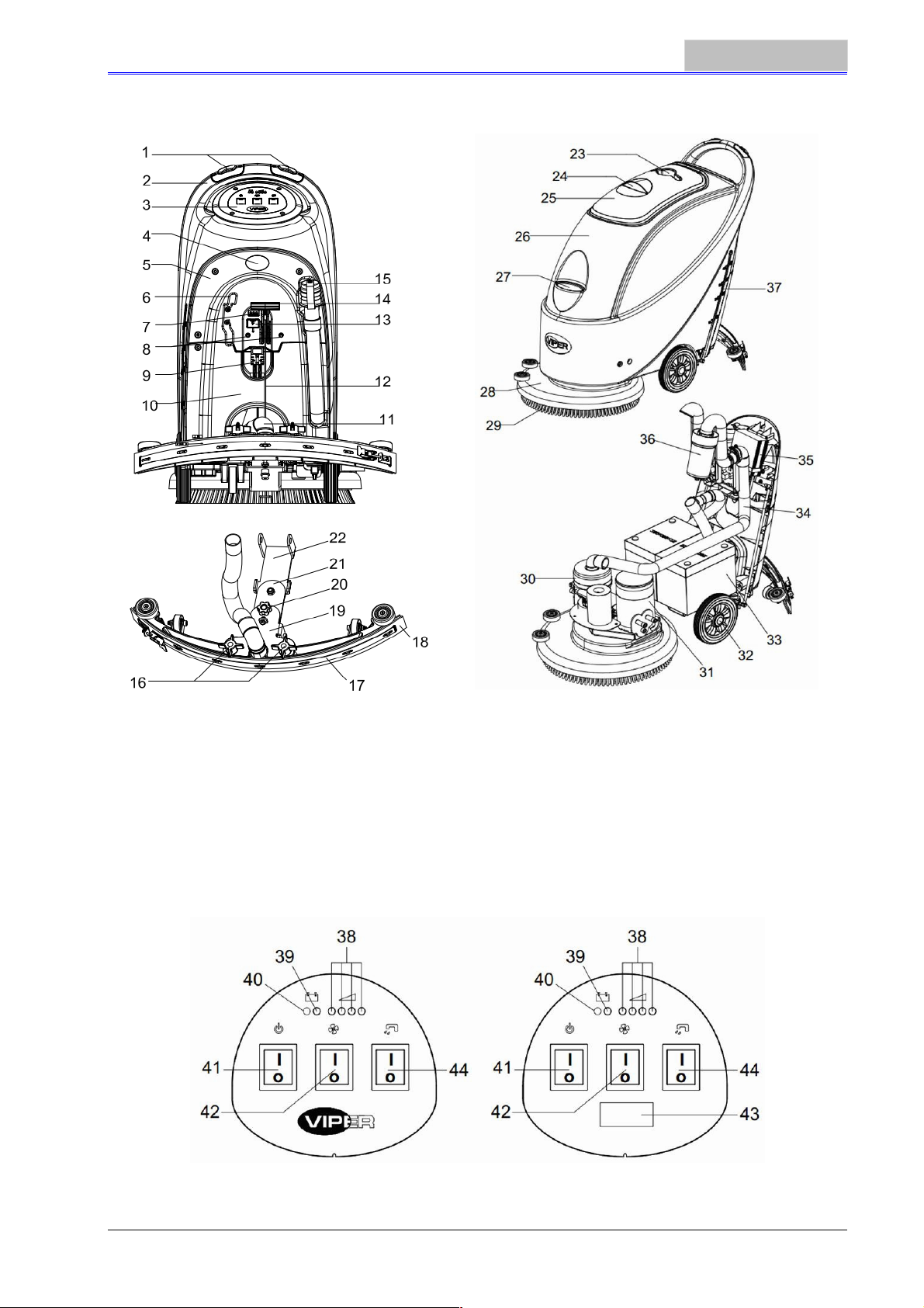
ABBILDUNG DES GERÄTAUFBAUS
BEDIENUNGSANLEITUNG
DEUTSCH
Abbildung 1
ÜBERBLICK ÜBER DAS BEDIENFELD (Abbildung 2)
38. Batterieladeanzeige (grün, wenn aufgeladen)
39. Ladeanzeige, bei erschöpfter Batterie (rot)
40. Ladeanzeige, bei erschöpfter Batterie (rot)
41. Netzschalter
42. Schalter, Absaugung
43. Stundenzähle(optional, wird verwendet, um die Arbeitszeit der Bürste zu erfassen)
44. Magnetventil-Schalter zur Wassermengensteuerung
AS430B AS510B
Abbildung 2
23
Page 26
DEUTSCH
BEDIENUNGSANLEITUNG
ANZEIGEFENSTER DER BATTERIELADUNGSANZEIGE (Abbildung 3)
(Optional, für Modelle mit eingebautem Ladegerät)
1. Wenn der Ladevorgang beginnt, blinkt die rote Kontrollleuchte
des Ladegeräts (45) ein paar Mal und wechselt dann zu einem
kontinuierlichen, roten Leuchten; die erste Phase der Aufladung
beginnt;
2. Nach einem gewissen Aufladezeitraum erlischt die rote
Kontrollleuchte des Ladegeräts (45). Eine gelbe
Kontrollleuchte (46) leuchtet dauerhaft: die zweite Phase der
Aufladung beginnt;
3. Nach einer Aufladedauer von ca. 10 Stunden erlischt die gelbe
Kontrollleuchte (46). Die grüne Anzeige (47) leuchtet dauerhaft,
das bedeutet, dass die Batterie voll aufgeladen ist und der
Abbildung 3
Ladevorgang beendet ist.
HINWEIS
1) Wenn während des Ladevorgangs, die gelbe Anzeige blinkt: ist der Batterietyp
2) Wenn die rote Kontrollleuchte blinkt: ist ein Kurzschluss im Ladegerät
nicht mit dem Ladegerät kompatibel oder die Batterie ist nicht richtig
angeschlossen oder am Ausgangsanschluss ist ein Kurzschluss aufgetreten.
aufgetreten. (Weitere Details entnehmen Sie bitte den entsprechenden
Abschnitten der Anleitung für das Ladegerät.)
BEDIENUNGSANLEITUNG
WARNUNG
Auf bestimmten Teilen des Geräts befinden sind einige Hinweiszeichen:
----
GEFAHR
Wenn der Anwender diese Gebrauchsanweisung liest, muss er den Symbolen auf diesen Schildern
besondere Aufmerksamkeit schenken.
Unter keinen Umständen dürfen diese Zeichen abgedeckt werden. Wenn sie beschädigt sind,
ersetzen Sie sie bitte sofort.
BATTERIEINSTALLATION UND -EINSTELLUNG DES NEUEN GERÄTS
Überprüfen Sie vor der Installation, ob die Batterie beschädigt ist.
Trennen Sie den Batteriestecker und den Stecker des eingebauten
Ladegeräts.
Seien Sie vorsichtig, wenn Sie die Batterie berühren.
Dieses Gerät benötigt zwei (2) 12-V-Batterien. Verbinden Sie sie, wie es
in Abbildung 4 auf der rechten Seite dargestellt ist.
Dieses Gerät kann von einem der folgenden Modelle versorgt werden:
a) Batterien (NASS oder GEL / AGM) sind bereits installiert und können jederzeit genutzt
----
----
----
werden.
WARNUNG
ACHTUNG
VERWENDUNG
WARNUNG
Wenn die Batterie unsachgemäß installiert oder fehlerhaft angeschlossen wird,
können die elektrischen Komponenten des Geräts schwer beschädigt werden. Die
Batterie darf nur von qualifiziertem Fachpersonal installiert werden. Stellen Sie
gemäß der Batterie-Modellnummer (NASS oder GEL) die funktionale Platine und
das eingebaute Ladegerät (optional) ein.
24
Page 27
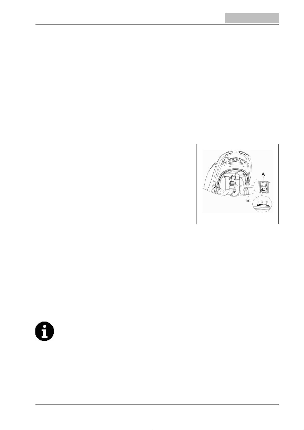
Abbildung 5
BEDIENUNGSANLEITUNG
1. Überprüfen Sie die Batterie. Schließen Sie mit dem Stecker (9) die Batterie an das Gerät an.
2. (Gilt nur für AS430B und AS510B): Drücken Sie den Ein/Aus-Schalter (41) nach unten. Wenn die
grüne Leuchte leuchtet, ist die Batterie einsatzbereit.
Wenn die gelbe oder rote Leuchte leuchtet, zeigt dies an, dass die Batterie aufgeladen werden
muss. (Siehe Abschnitt über Wartung zugehöriger Verfahren).
b) Ohne Batterien
1. Kaufen Sie eine ähnliche Batterie (siehe Abschnitt über technische Parameter). Informationen
über die Auswahl der Batterie erhalten Sie von qualifizierten Vertretern für Batterien.
2. Stellen Sie das Gerät und das eingebaute Ladegerät (falls vorhanden) nach der Art der Batterien
ein (NASS oder GEL/AGM). Lesen Sie auch den folgenden Abschnitt über die Installation der
Batterie.
DEUTSCH
BATTERIEINSTALLATION UND EINSTELLUNG DES BATTERIETYPS (NASS ODER
GEL/AGM)
Stellen Sie gemäß dem Batterietyp (NASS oder GEL/AGM) die elektrische Leiterplatte auf dem
eingebauten Ladegerät ein. Die Verfahrensschritte sind wie folgt:
1. Achten Sie darauf, dass der Batteriestecker getrennt ist. Wenn das Gerät auf "AGM"-Batterie
zum Zeitpunkt der Werksauslieferung eingestellt ist, gehen
Sie direkt zu Schritt 8, andernfalls führen Sie die Schritte 2, 3
und 4 durch.
2. Entfernen Sie den Ablaufschlauch (15)
3. Wenn das Gerät mit einem eingebauten Ladegerät
ausgestattet ist, entfernen Sie das Ladekabel von der Rolle.
4. Nehmen Sie den Gerätedeckel ab (5) und lösen Sie die
Schrauben der Batterieabdeckung (10). Entfernen Sie die
Schrauben der PCB-Platine. Der DIP-Schalter (B) für die
Einstellung des Batterie-Modells ist zu sehen,
wenn ?Umklappen der Platine werden. (Siehe Abbildung 5)
5. Stellen Sie den Mikro-DIP-Schalter (B) auf die Position
"NASS".
6. Führen Sie die Schritte 3, 4 und 5 in umgekehrter
Reihenfolge durch.
Einsetzen der Batterien
7. Trennen Sie den Batteriestecker (9).
8. Öffnen Sie die Schmutzwassertank-Abdeckung (25) und überprüfen Sie, ob der
Schmutzwassertank leer ist oder nicht, wenn nicht, entleeren Sie ihn durch den Ablaufschlauch
(15).
9. Lösen Sie die Feststellknöpfe des Abstreifers (16), entfernen Sie den Anschluss, der das
Vakuumrohr für Abfälle (11) mit dem Abstreifer verbindet, und entfernen Sie dann den Abstreifer.
10. Lösen Sie die Schrauben der Batterieabdeckung (10), und entfernen Sie die Abdeckung.
11. Lösen Sie den Anschluss der Abstreifer-Zugschnur (12), die mit der Abstreiferhalterung (19)
verbunden ist, und hängen Sie die Abstreifer-Zugschnur nach oben.
12. Hängen Sie den Ablaufschlauch (15) und das Vakuumrohr für Abfälle (11) nach oben.
13. Drücken Sie, je nach Größe der Batterie, die Fixierungsplatte im Batteriefach ganz nach innen.
HINWEIS
Die Abmessung der Batterie darf diese Größe nicht überschreiten: H x B x T 330 mm x
170 mm x 260 mm.
Entsprechend der unterschiedlichen Abmessungen der Batterien, sind die Anforderungen für
die Auswahl der fest eingebauten Batterien wie folgt:
1) Für Batterien mit einer Länge unter 270 mm verwenden Sie 2 Teile der Fixierungsplatte
(B, Abbildung 6) und platzieren Sie sie nebeneinander im Inneren der Wassertank-
Batterie;
2) Für Batterien mit einer Länge zwischen 310 mm und 270 mm verwenden Sie 1 Teil der
Fixierungsplatte (B, Abbildung 6) und platzieren Sie sie in der Wassertank-Batterie;
3) Für Batterien mit einer Länge zwischen 330 mm und 310 mm besteht keine
Notwendigkeit, die Position mit der Fixierungsplatte zu fixieren.
25
Page 28
DEUTSCH
BEDIENUNGSANLEITUNG
Abbildung 6
14. Setzen Sie die Batterie mit speziell angefertigten Batterie-Installationsgeräten ein (A, Abbildung
7). Nachdem die Batterie eingesetzt ist, entfernen Sie die Batterie-Installationsgeräte, und
installieren Sie die Batterie-Fixierungshalterung (B, Abbildung 7).
Abbildung 7
15. Stecken Sie den Batterie-Anschluss (C, Abbildung 7) durch das Loch auf der Oberseite der
Batterieabdeckung, stecken Sie dann den Ablaufschlauch durch das rechte Loch der
Batterieabdeckung. Fixieren Sie die Batterieabdeckung mit 4 Schrauben, und installieren Sie
dann nacheinander die Abstreifer-Zugschnur, den Ablaufschlauch und den Abstreifer.
Aufladen der Batterie
16. Aufladen der Batterie (siehe angegebene Schritte im Abschnitt Wartung).
VOR INBETRIEBNAHME DES GERÄTS
MONTIEREN UND ENTFERNEN DER BÜRSTEN/PAD-HALTERUNG
HINWEIS
Je nach Art des zu reinigenden Bodens kann das Gerät mit Bürste (Abbildung 8, A)
oder einem Pad-Halter (Abbildung 8, B und C) ausgestattet werden.
ACHTUNG!
Bei der manuellen Installation oder Entfernung des Bürsten/Pad-Halters überprüfen
Sie zuerst, ob alle Schalter in der Aus-Position sind, und heben Sie den Abstreifer
über den Boden an. Erst dann kann am Bürsten- oder Pad-Halter gearbeitet werden.
Ziehen Sie außerdem Schutzhandschuhe an, um zu vermeiden, dass Sie sich durch
Fragmente verletzen.
26
Page 29
BEDIENUNGSANLEITUNG
1. (Gilt nur für AS430B und AS510B): Stellen Sie sicher, dass sich der Schalter (41) in der
Trennposition (O) befindet.
2. Drücken Sie den Lenker (2) nach unten, um das Tankgehäuse (26) anzuheben.
3. Legen Sie die Bürste (A) oder den Pad-Halter (B - C) unter das Gehäuse.
4. Verwenden Sie den Lenker (2) zum Absenken des Tankgehäuses (26), damit es in Kontakt mit
der Bürste oder dem Pad-Halter kommt.
5. Um den Bürsten/Pad-Halter automatisch zu installieren, schalten Sie den Netzschalter (41) auf
die "I"-Position und drücken Sie den Sicherheitsschalter
(1). Schieben Sie das Gerät vorsichtig vorwärts, sodass
sich die Riemenscheibe an der Unterseite des
Tankgehäuses an der Bürste oder dem Pad-Halter
ausrichten kann, die dann installiert werden können. Dann
lassen Sie den Sicherheitsschalter los. Falls erforderlich,
wiederholen Sie diesen Vorgang, bis der Bürsten/PadHalter installiert ist.
6. Wenn sich Schritt 5 als zu schwierig erweist, verwenden
Sie die manuelle Methode, indem Sie der Pfeilspitze (D)
folgen, um den Bürsten/Pad-Halter (wie in Abbildung 8
gezeigt) zu installieren.
7. Um den Bürsten/Pad-Halter automatisch zu entfernen,
schalten Sie den Netzschalter (41) auf die "O"-Position.
Halten Sie mit der Hand den Lenker, und drücken Sie das Gerät nach unten, bis das
Führungsrad den Boden berührt und der Bürsten/Pad-Halter in der Luft hängt. Schalten Sie den
Netzschalter (41) auf die "I"-Position, und drücken Sie den Sicherheitsschalter nach unten, damit
sich die Bürste oder der Pad-Halter dreht, bis der Bürsten/Pad-Halter auf den Boden fällt.
8. Wenn sich Schritt Nr. 7 als zu schwierig erweist, verwenden Sie das manuelle Verfahren, indem
Sie den Bürsten/Pad-Halter entgegen der normalen Drehrichtung drehen, er kann dann entfernt
werden. (Wie in Abbildung 8 dargestellt.)
Abbildung 8
DEUTSCH
EINSTELLEN DER SAUGLEISTE
9. Installieren Sie die Saugleiste und drehen Sie ihn mit dem Griff fest. Schließen Sie dann den
Saugschlauch an die Saugleiste an.
10. Passen Sie die Saugleiste durch den Einstellgriff (A) an (siehe Abbildung 9).
1) Wenn der mittlere Teil der hinteren Saugleistes, Abschnitt B, einen Abstand zum Boden hat
oder der nach unten gerichtete Druck relativ schwach ist, passen Sie den Griff in Richtung
gegen den Uhrzeigersinn an, bis die gesamte Länge der hinteren Saugleiste den Boden
berührt. Die vordere Sauglippe sollte den Boden leicht berühren.
2) Wenn die beiden Enden der hinteren Sauglippe, Abschnitt C und D, einen Abstand zum Boden
haben oder der nach unten gerichtete Druck relativ schwach ist, passen Sie den Griff in
Richtung des Uhrzeigersinns an, bis die gesamte Länge der hinteren Sauglippe den Boden
berührt. Die vordere Sauglippe sollte den Boden leicht berühren.
Abbildung 9
27
Page 30
DEUTSCH
Füllung des Frischwassertanks
ACHTUNG!
Es dürfen nur nichtentflammbare Reinigungsmittel mit geringer Schaumbildung
verwendet werden. Diese Reinigungsmittel müssen für die Verwendung in
Nassreinigern geeignet sein.
11. Öffnen Sie die Wasserzulauf-Abdeckung (27) und füllen Sie Wasser in den Frischwassertank.
Überfüllen Sie den Tank nicht. Das Auffüllen bis zur Kante des Filterhalters des Wasserzulaufs ist
ausreichend. Bei der Herstellung der Reinigungslösungen folgen Sie bitte den
Verdünnungsverhältnissen, die der Hersteller angegeben hat. Die Wassertemperatur sollte 40 °C
nicht überschreiten.
BEDIENUNGSANLEITUNG
REGULIERUNG DES WASSERDURCHFLUSSES
WARNUNG!
Die Regulierung des Kugelventilhebels (A,
Abbildung 10) darf nur durchgeführt werden, wenn
der Netzschalter (41) auf der Position "O" steht.
12. Die Wasserdurchflussmenge kann durch den Kugelventilhebel
(A, Abbildung 10), entsprechend der Wassermenge,
angepasst werden, die zum Scheuern erforderlich ist.
START UND STOPP DES GERÄTS
Inbetriebnahme des Geräts
1. Führen Sie die vorbereitenden Schritte, wie oben angegeben, durch.
2. Drücken Sie den Netzschalter (41) auf die "I"-Position.
3. Verwenden Sie den Griff des Abstreifers (41), um ihn abzusenken.
4. Drücken Sie den Vakuumpumpen-Schalter (42) auf die "I"-Position.
5. Drücken Sie den Kontrollschalter für die Wasserdurchflussmenge (44) auf die "I"-Position.
(Funktioniert gleichzeitig mit dem Sicherheitsschalter (1), um die Funktion des Magnetventils zu
steuern.)
6. Halten Sie den Sicherheitsschalter (1) und schieben Sie das Gerät, um es zu bewegen. Die
Bürste (29) beginnt sich zu drehen, und das Gerät beginnt seine Reinigungsarbeit.
VERWENDUNG: Die Methode, um das Gerät zu schieben
Eines der Gerätemerkmale ist die Installation
von zwei Sicherheitsschaltern auf beiden Seiten
des Lenkers. Jeder Sicherheitsschalter kann
unabhängig vom anderen die Funktion der
Bürste zu überwachen. Im Einsatz vereinfachen
sie die Steuerung der Gerätefunktion.
Aus Erfahrung kann gesagt werden, dass die
Methode, das Gerät zu bewegen, wie in der
rechten Abbildung 11 dargestellt, geeigneter ist.
Die Arbeitshaltung der Hände des Anwenders ist
angenehmer und Arbeitsermüdung wird
reduziert. Dem Anwender wird daher empfohlen,
das Gerät auf diese Weise zu bewegen.
Abbildung 10
Abbildung 11
28
Page 31

BEDIENUNGSANLEITUNG
Ausschalten des Geräts
7. Wenn Sie die Gerätenutzung beendet haben, entfernen
Sie zuerst den Bürsten/Pad-Halter (siehe Schritte im
Abschnitt Montieren und Entfernen der Bürsten/PadHalterung).
8. Lassen Sie den Sicherheitsschalter (1) los, um den
Bürsten/Pad-Halter und das Magnetventil auszuschalten.
9. Drücken Sie den Vakuumpumpen-Schalter (42) auf die
"O"-Position. Die Vakuumpumpe verzögert die
Abschaltung für 5 Sekunden, bevor die Funktion
eingestellt wird.
10. Drücken Sie den Kontrollschalter für die
Wasserdurchflussmenge (44) auf die "O"-Position, um das
Magnetventil vollständig auszuschalten.
11. Drücken Sie den Netzschalter (41) auf die "O"-Position.
12. Verwenden Sie den Hebegriff der Saugleiste (14), um den
Abstreifer anzuheben.
13. Greifen Sie den Lenker (2) und kippen Sie vorsichtig das Gerät zurück, bis das Führungsrad (B)
den Boden berührt. Siehe Abbildung 12
Abbildung 12
DEUTSCH
EINSATZ DES GERÄTS (SCHEUERN UND TROCKNEN)
1. Starten Sie das Gerät gemäß der obigen Beschreibung.
2. Halten Sie den Sicherheitsschalter (1) (wie in Abbildung 11 dargestellt), schieben Sie das Gerät,
um es zu bewegen, und beginnen Sie mit der Reinigung.
3. Wenn nötig, schalten Sie das Gerät aus, und stellen Sie den Regulierungsgriff des Abstreifers ein.
(Siehe die Schritte zum Einstellen der Abstreiferposition)
4. Wenn nötig, schalten Sie das Gerät aus, und stellen Sie die Wasserdurchflussmenge mit dem
Kugelventilhebel ein. (Siehe die Schritte zur Einstellung der Wasserdurchflussmenge.)
ACHTUNG!
Um eine Beschädigung des Bodens zu vermeiden, wenn das Gerät ohne
Vorwärtsbewegung an einem Platz steht, schalten Sie den Netzschalter (41) aus.
Batterieentladung während des Einsatzes
5. Nur wenn die grüne Warnleuchte (38) kontinuierlich leuchtet, ist die Stromversorgung durch die
Batterie für den normalen Betrieb des Geräts ausreichend.
HINWEIS
Wenn alle vier grünen Leuchten (38) eingeschaltet sind, bedeutet das, dass die
Batterie vollständig aufgeladen ist.
Wenn nur die letzte grüne Leuchte (38) eingeschaltet ist und beginnt zu blinken, wird
empfohlen, die Batterie aufzuladen, da das Gerät automatisch nach ein paar Minuten
anhält.
Nachdem die letzte grüne Leuchte (38) erlischt, und die roten Leuchten (39 und 40)
zu blinken beginnen, wird das Gerät automatisch nach wenigen Sekunden
angehalten. (Siehe Schritte im Abschnitt Wartung).
ACHTUNG!
Verwenden Sie das Gerät nicht, wenn die Stromversorgung der Batterie nicht
ausreicht, um eine Beschädigung der Batterie und die Verkürzung der Lebensdauer
der Batterie zu vermeiden.
TANK ENTLEEREN
Wenn der Schmutzwassertank voll ist, blockiert ein Schwimmer in der automatischen
Abschalteinrichtung (36) den Zufluss, der mit der Vakuumpumpe verbunden ist. Bei einer plötzlichen
Erhöhung des Geräuschpegels der Vakuumpumpe kann davon ausgegangen werden, dass die
Vakuumpumpe bereits überlastet wird und eine sofortige Ableitung des Abwassers erforderlich ist.
29
Page 32

DEUTSCH
ACHTUNG!
Wenn sich die Vakuumpumpe plötzlich ausschaltet (z. B. weil das Gerät ruckartig
bewegt wird, was zu einer Aktivierung des Schwimmers führt), und wenn eine
Fortsetzung des Betriebs erforderlich ist, führen Sie bitte die folgenden Schritte
aus: Drücken Sie die Netzschalter (41 und 42), um das Gerät und die Vakuumpumpe
auszuschalten, und öffnen Sie die Schmutzwassertank-Abdeckung (25), um zu
überprüfen, ob der Schwimmer im Schwimmer-Filter an die Wasseroberfläche
zurückgekehrt ist. Dann schließen Sie die Schmutzwassertank-Abdeckung (25) und
drücken die Netzschalter (41 und 42), um das Gerät und die Vakuumpumpe
einzuschalten.
Wenn der Schmutzwassertank vollständig mit Abwasser gefüllt ist, führen Sie die folgenden Schritte
aus, um ihn zu entleeren.
Entleeren des Schmutzwassertanks
1. Schalten Sie das Gerät aus.
2. Heben Sie mit dem Hebegriff der Sauglippe (14) den Abstreifer an.
3. Bewegen Sie das Gerät zu einem geeigneten Entsorgungsplatz.
4. Greifen Sie den Lenker (2) und kippen Sie vorsichtig das Gerät zurück, bis das Führungsrad den
Boden berührt. (Ankoppeln des Geräts, siehe Maßnahmen im
Abschnitt Anhalten des Geräts.)
5. Nehmen Sie den Ablaufschlauch vom Befestigungsclip,
biegen Sie das obere Ende des Ablaufschlauchs (wie in A,
Abbildung 13, dargestellt). Öffnen Sie dann die Abdeckung
des Ablaufschlauchs, senken Sie den Ablaufschlauch auf ein
niedriges Niveau oder auf den Boden, um das Wasser
abzulassen. Alternativ können Sie den Ablaufschlauch in eine
niedrige Position oder auf den Boden absenken, damit der
Wasserablauf nach unten zeigt (wie in B, Abbildung 13,
dargestellt). Drehen Sie dann die Abdeckung des
Wasserablaufschlauchs auf, um das Abwasser aus dem Tank
zu leiten. Reinigen Sie nach der vollständigen Entleerung den
Schmutzwassertank mit sauberem Wasser.
ACHTUNG!
Beim Ablassen des Abwassers muss das Vakuum-Rohr für Abfälle gefaltet oder
abgesenkt werden (wie in Abbildung 13, A oder B dargestellt). Öffnen Sie dann den
Deckel des Vakuum-Rohrs für Abfälle, um das Wasser abzulassen. Heben Sie den
Ablauf des Vakuum-Rohrs für Abfälle nicht nach oben an, um das Wasser vertikal
abzulassen. Damit vermeiden Sie, dass Abwasser auf den Anwender spritzt.
Entleeren des Frischwassertanks
6. Führen Sie die Schritte 1 bis 4. aus
7. Wie in Abbildung 14 dargestellt, öffnen Sie den Deckel des
Frischwassertanks (A) im Gegenuhrzeigersinn, und entleeren
den Frischwassertrank vollständig. Verwenden Sie sauberes
Wasser, um das Innere des Frischwassertanks zu reinigen.
Wenn der Arbeitsgang abgeschlossen ist, drehen Sie den
Deckel des Frischwassertanks (A) fest im Uhrzeigersinn in
Richtung B.
BEDIENUNGSANLEITUNG
Abbildung 13
NACH DEM EINSATZ DES GERÄTS
Nach dem Einsatz und bevor Sie das Gerät verstauen, führen Sie
die folgenden Schritte aus:
1. Folgen Sie den Anweisungen im vorgenannten Abschnitt über
die Installation und Entfernung des Bürsten/Pad-Halters, und
entfernen Sie den Bürsten/Pad-Halter.
2. Folgen Sie den Anweisungen in den entsprechenden Abschnitten, und entleeren Sie vollständig
den Frischwassertank und den Schmutzwassertank.
3. Führen Sie die tägliche Wartung durch (siehe Abschnitt Wartung).
Abbildung 14
30
Page 33

BEDIENUNGSANLEITUNG
4. Lagern Sie das Gerät, einschließlich des Bürsten/Pad-Halters und Saugleiste, an einem sauberen
und trockenen Ort. Die Saugleiste sollte angehoben oder abgenommen werden.
DEUTSCH
STILLSTANDSZEITEN
Wenn das Gerät für mehr als 30 Tage nicht genutzt wird, gehen Sie nach folgender Art und Weise vor:
1. Führen Sie die notwendigen Maßnahmen durch, die nach dem normalen Gebrauch des Geräts
auszuführen sind.
2. Ziehen Sie den Stecker (9), der die Batterie und das Gerät verbindet.
3. Um die Batterie nicht zu beschädigen, und wenn das Gerät länger als 3 Monate nicht genutzt
wird, bitte laden Sie die Batterie einmal alle 3 Monate auf.
VOR DER ERSTEN VERWENDUNG
Nach der Verwendung für die ersten 9 Stunden überprüfen Sie bitte alle Teile, um sicherzustellen,
dass sich nichts gelockert hat oder während des Betriebs beschädigt wurde, und überprüfen Sie, ob
es irgendwelche sichtbaren Schäden oder Lecks gibt.
WARTUNG UND PFLEGE
Die Lebensdauer und die maximale Betriebssicherheit des Geräts werden durch die richtige und
rechtzeitige Wartung und Pflege gewährleistet.
Die folgende Tabelle enthält einen allgemeinen Wartungsplan für das Gerät. Die Zeitabstände der
Wartung werden zu einem großen Teil von den Arbeitsbedingungen des Geräts bestimmt. Diese
Zeitintervalle sollten von den verantwortlichen Personen für die Wartung und Pflege formuliert werden.
WARNUNG!
Diese Verfahren sollten erst durchgeführt werden, nachdem das Gerät ausgeschaltet
ist und die Verbindung zwischen dem Gerät und der Batterie getrennt wurde. Bevor
Sie mit einer der Wartungsarbeiten beginnen, lesen Sie bitte sorgfältig die damit
verbundenen Sicherheits-Abschnitte.
Alle Wartungsarbeiten, die im Plan aufgeführt sind oder alle zusätzlichen Wartungsarbeiten dürfen nur
durch qualifiziertes Personal oder autorisierte Service-Zentren durchgeführt werden.
Diese Anleitung enthält nur die einfachsten und häufigsten Wartungsarbeiten.
Alle Wartungsarbeiten, die nicht in dieser Tabelle der geplanten Wartungsarbeiten aufgeführt sind,
entnehmen Sie bitte der Wartungsanleitung des Service-Centers.
TABELLE DER PLANMÄSSIGEN WARTUNGSARBEITEN
Verfahren
Batterie aufladen
Abstreifer reinigen
Bürsten/Pad-Halter reinigen
Frischwassertank und Schwimmerfilter reinigen,
Dichtungsband des Wassertanks überprüfen
Abstreiferband überprüfen und wechseln
Frischwasserfilter reinigen
Vakuumpumpen-Filter reinigen
Flüssigkeitsstand der WET-Batterie überprüfen
Dichtheit von Schrauben und Muttern überprüfen
Kohlebürste des Bürsten/Pad-Halter-Motors
überprüfen und wechseln
Kohlebürste der Vakuumpumpe überprüfen und
wechseln
Täglich,
Gerät
Nach der
Benutzung
Wöchen-
tlich
Alle
6 Monate
(1)
Jährlich
(2)
(2)
(1) Durchführung nach den ersten 9 Einsatzstunden.
(2) Diese Wartung muss von einem autorisierten VIPER-Service Center durchgeführt werden.
31
Page 34

DEUTSCH
BEDIENUNGSANLEITUNG
AUFLADEN DER BATTERIE
HINWEIS
Die Batterie muss aufgeladen werden, wenn die gelben oder roten Warnleuchten
aufleuchten, oder jedes Mal, wenn der Einsatz beendet wurde.
ACHTUNG!
Halten Sie die Batterie in einem voll aufgeladenen Zustand, um die Lebensdauer der
Batterie zu verlängern.
ACHTUNG!
Sobald die Leistung der Batterie unzureichend ist, muss die Batterie so bald wie
möglich aufgeladen werden. Überprüfen Sie bitte das Ladegerät mindestens einmal
pro Woche.
ACHTUNG!
Wenn das Gerät nicht mit einem eingebauten Ladegerät ausgestattet ist, wählen Sie
bitte ein geeignetes externes Ladegerät, um die Batterie aufzuladen.
WARNUNG!
Besondere Vorsicht ist beim Laden der Batterie geboten, da es während des
Ladevorgangs zum Austritt von Säure kommen kann. Batteriesäure ist ätzend. Wenn
die Haut oder das Auge versehentlich in Kontakt mit Batteriesäure kommt, spülen Sie
mit viel Wasser und suchen Sie sofort einen Arzt auf.
1. Öffnen Sie die Abdeckung des Schmutzwassertanks (25) und überprüfen Sie, ob der Tank leer ist
oder nicht. Wenn er nicht leer ist, leeren Sie ihn über den Ablaufschlauch. 15.
2. Bringen Sie das Gerät an einen speziellen Ladeplatz.
3. Drücken Sie den Netzschalter (41) auf die "O"-Position und schalten Sie das Gerät aus.
4. Gilt nur für WET-Wasser-Addition-Batterie
-
Überprüfen Sie den Füllstand der Elektrolytlösung in der Batterie. Falls erforderlich, füllen Sie
sie durch den Deckel auf.
-
Halten Sie alle Deckel geöffnet.
-
Falls erforderlich, reinigen Sie die Oberseite der Batterie.
5. Wählen Sie eines der folgenden Verfahren, um die Batterie, gemäß dem verwendeten
Batteriemodell, aufzuladen.
Aufladen einer Batterie mit einem externen Ladegerät
6. Überprüfen Sie, gemäß der dazugehörigen Bedienungsanleitung, ob das externe Ladegerät
geeignet ist. Die Ausgangsspannung muss DC 24 V betragen.
7. Schließen Sie den Batterie-Stecker an den externen Anschluss an, und verbinden Sie den
externen Anschluss mit dem Stromnetz.
8. Wenn der Ladevorgang abgeschlossen ist, verbinden Sie den Ladestecker der Batterie mit dem
Gerät.
Aufladen einer Batterie mit einem eingebauten Ladegerät (optional)
9. Entfernen Sie den Gummideckel am Ende des Batterie-Ladeanschlusses.
10. Verbinden Sie das Ende des Batterie-Ladeanschlusses über ein Ladeanschlusskabel mit dem
Stromnetz. (Überprüfen Sie, ob die Eingangsspannung des eingebauten Ladegeräts 220 V 240 V und die Ausgangsspannung 24 V betragen und die Frequenz den Anforderungen
entspricht.) Wenn das Ladegerät an das Stromnetz angeschlossen ist, werden alle anderen
Funktionen automatisch ausgeschaltet. Wenn die rote Warnleuchte des eingebauten Ladegeräts
kontinuierlich leuchtet, lädt das Ladegerät die Batterie.
11. Wenn die grüne Warnleuchte (47) leuchtet, wird damit anzeigt, dass der Batterie-Ladevorgang
abgeschlossen ist.
12. Wenn der Ladevorgang abgeschlossen ist, entfernen Sie das Ladeanschlusskabel vom Ende des
Batterie-Ladeanschlusses und der Stromversorgung, und setzen Sie den Gummideckel wieder
auf.
13. Trennen Sie das Ladeanschlusskabel von der Stromversorgung, und wickeln Sie das Kabel auf
die Rolle (6).
32
Page 35

BEDIENUNGSANLEITUNG
HINWEIS
Wenn Sie weitere Informationen über das eingebaute Ladegerät (35) benötigen,
entnehmen Sie sie bitte der dazugehörigen Bedienungsanleitung.
DEUTSCH
REINIGEN DES ABSTREIFERS
HINWEIS
Um die optimale Wirkung des Wasser-Vakuums zu gewährleisten, muss der
Abstreifer sauber gehalten werden, und das Abstreiferband muss in gutem
Zustand bleiben.
ACHTUNG!
Es wird empfohlen, bei der Reinigung des Abstreifers Schutzhandschuhe zu
tragen, da dieser scharfe Fragmente enthalten kann.
1. Stellen Sie das Gerät auf eine ebene und glatte Oberfläche.
2. Drücken Sie den Netzschalter (41) auf die "O"-Position und schalten Sie das Gerät aus.
3. Lösen Sie die Feststellknöpfe (16) des Abstreifers; entfernen Sie den Anschluss für die
Verbindung des Schmutzwasser-Vakuumrohrs zum Abstreifer, und entfernen Sie den Abstreifer.
4. Verwenden Sie den Hebegriff des Abstreifers (14), um den Tragrahmen des Abstreifers
anzuheben.
5. Reinigen Sie den Abstreifer (Abbildung 15). Reinigen Sie insbesondere die Nut (A, Abbildung
15), und entfernen Sie Schmutz und Fragmente aus dem Vakuum-Rohr. Prüfen Sie, ob das
vordere Abstreiferband (C) und das hintere Abstreiferband (D) intakt sind, und ob es
gebrochenen Kanten und Risse gibt. Tauschen Sie sie, falls erforderlich, aus (siehe Schritte im
folgenden Abschnitt).
6. Installieren Sie den Abstreifer in der umgekehrten Reihenfolge der oben genannten Schritte.
ÜBERPRÜFEN UND AUSTAUSCHEN DES ABSTREIFERBANDS
1. Folgen Sie den Anweisungen, die im Abschnitt Reinigen des Abstreifers aufgeführt sind
(Abbildung 15).
2. Überprüfen Sie die Kante (E, Abbildung 15) des vorderen Abstreiferbands und die Kante (F) des
hinteren Abstreiferbands (D). Sie sollten über die gesamte Länge auf der gleichen Ebene liegen.
Passen Sie sonst ihre Höhen durch folgende Vorgehensweise an.
-
Lösen Sie die Klammer (G), um das hintere Abstreiferband (D) von der Halterung (M) zu lösen,
um die Position des Abstreifers anzupassen. Arretieren Sie nach der Einstellung die Klammer
wieder.
-
Lösen Sie die Schraube am Griff (I), um das vordere Abstreiferband anzupassen (C); ziehen
Sie die Griffschraube nach der Einstellung wieder fest.
3. Prüfen Sie, ob das vordere Abstreiferband (C) und das hintere Abstreiferband (D) intakt sind, und
ob es gebrochenen Kanten und Risse gibt. Falls erforderlich, wechseln Sie sie in der folgenden
Art und Weise aus. Überprüfen Sie die vordere Kante des hinteren Abstreiferbands (J), ob es
abgenutzt ist. Wenn es abgenutzt ist, kann es anders herum installiert werden (die Oberkante
muss intakt sein). Wenn die obere Kante ebenfalls abgenutzt ist, wechseln Sie das Band wie folgt
aus:
-
Öffnen Sie die Klammer (G), um das Druckblatt von der Halterung (M) zu lösen, entfernen Sie
die Klammerschiene (K), und wechseln Sie dann das hintere Abstreiferband (D) aus oder
drehen Sie es anders herum. Installieren Sie das hintere Abstreiferband in der umgekehrten
Reihenfolge.
- Lösen Sie die Griffschraube (I) und entfernen Sie die Frontklammerschiene (L), und wechseln
Sie dann den vorderen Abstreifer (C).
Installieren Sie das vordere Abstreiferband in der umgekehrten Reihenfolge.
Passen Sie das Niveau des hinteren und vorderen Abstreiferbands nach Austausch des
Abstreiferbands (oder der umgekehrten Installation) an, indem Sie den oben beschriebenen
Schritten folgen.
4. Verbinden Sie das Vakuum-Rohr (11) mit dem Abstreifer.
5. Installieren Sie den Abstreifer und verwenden Sie den Knopf (16), um ihn festzuziehen, und dann
schließen Sie das Vakuum-Rohr an den Abstreifer an.
6. Falls nötig, stellen Sie den Abstreifer durch das Einstellrad (20) ein (siehe Verfahren zum
Einstellen der Abstreiferposition).
33
Page 36

DEUTSCH
BEDIENUNGSANLEITUNG
Abbildung 15
REINIGEN VON BÜRSTE/POLIERPAD
ACHTUNG!
Es wird empfohlen, bei der Reinigung des Bürsten/Pad-Halters Schutzhandschuhe
zu tragen, da scharfe Fragmente enthalten sein können.
1. Entfernen Sie den Bürsten/Pad-Halter in der Art und Weise, wie in den vorangegangenen
Abschnitten beschrieben ist.
2. Reinigen Sie der Bürsten/Pad-Halter mit Wasser und Reinigungsmittel.
3. Überprüfen Sie die Vollständigkeit und Abnutzung der Borsten auf der Bürste und, falls
erforderlich, wechseln Sie die Bürste aus.
4. Überprüfen Sie den Abnutzungszustand des Pad-Halters und, falls erforderlich, wechseln Sie den
Pad-Halter aus.
REINIGEN DES SCHMUTZWASSERTANKS UND DES SCHWIMMFILTERSIEBS
1. Bewegen Sie das Gerät zu einem geeigneten Entsorgungsplatz.
2. Drücken Sie den Netzschalter (41) auf die "O"-Position und schalten Sie das Gerät aus.
3. Öffnen Sie die Abdeckung des Schmutzwassertanks (A, Abbildung 16), und entnehmen Sie den
Schwimmer (36) aus dem Schmutzwassertank.
4. Verwenden Sie klares Wasser zur Reinigung des Tankdeckels (A), der Tanks (B und C) und der
Schwimmer-Filterfassung (E). Lassen Sie durch das Schmutzwasserrohr (15) das gesamte
Wasser aus dem Wassertank ablaufen.
5. Folgen Sie, falls nötig, den Symbolen "Öffnen" und "Schließen", wie in Abbildung 16 dargestellt,
öffnen Sie den unteren Deckel (F) des Schwimmer-Filters und reinigen den Schwimmer (D), die
Schwimmer-Filterfassung (E) und den Filter-Schwamm (I). Fixieren Sie nach der Reinigung den
Schwimmer auf der Schwimmer-Filterfassung (E), und richten Sie die Markierungsnut (L) des
unteren Deckels (F) des Schwimmer-Filters nach der Markierungsnut (L) der SchwimmerFilterfassung (E) aus. Drehen Sie den unteren Deckel (F) des Schwimmer-Filters fest und
fixieren Sie den Filter-Schwamm (I) auf der Schwimmer-Filterfassung (E) und dann auf dem
Vakuum-Rohr (M).
6. Überprüfen Sie die Zuverlässigkeit des Dichtrings (G) der Wassertankabdeckung.
HINWEIS
Der Dichtungsring (G) des Wassertanks dient dazu, im Wassertank ein Vakuum zu
erzeugen. Er muss vollständig abgedichtet sein, um das Abwasser effektiv vom
Boden absaugen zu können.
Falls erforderlich, sollte der Dichtungsring des Wassertanks (G) aus der Nut (H) entnommen und
ausgetauscht werden. Beim Einsatz eines neuen Wassertank-Dichtrings, wie in Abbildung 16
unten dargestellt, installieren Sie den Anschluss im mittleren Bereich des hinteren Teils.
7. Prüfen Sie, ob die aufnehmende Oberfläche des Dichtrings (G) intakt ist und ausreichend
abdichtet.
8. Schließen Sie die Abdeckung des Schmutzwassertanks (A).
34
Page 37

BEDIENUNGSANLEITUNG
DEUTSCH
Abbildung 16
REINIGEN DES FRISCHWASSERTANKS
1. Lassen Sie das Wasser aus dem Frischwassertank in der Art und Weise ab, wie in den
entsprechenden Abschnitten beschrieben.
2. Stellen Sie das Gerät auf eine ebene und glatte Oberfläche.
3. Drücken Sie den Netzschalter (41) auf die "O"-Position und schalten Sie das Gerät aus.
4. Drehen Sie das Kugelventil des Ablasses zu (A, Abbildung 17) (es befindet sich an der
Unterseite des Geräts, hinter den Rädern). Position B Kugelventil geöffnet und Position C
Kugelventil geschlossen.
5. Entfernen Sie den transparenten Deckel (D) und dann den Filter (E), und installieren Sie ihn nach
der Reinigung auf der Filterabdeckung (F).
HINWEIS
Der Filter (E) muss genau auf die Position der Ausbuchtung (G) gesetzt werden.
6. Öffnen Sie das Kugelventil des Ablasses (A).
Filtersiebmarkierung
Abbildung 17
35
Page 38

DEUTSCH
BEDIENUNGSANLEITUNG
SCHALTKREISDIAGRAMM VON AS430B UND AS510B
FARBCODES
RD=ROT BN=BRAUN BU/BK=BLAU/SCHWARZ
BAT
D
EB1
EB2
ES
EV
F1
F2
F3
F4
M1
M2
SW1
SW2
SW3
SW4
HM
Batterie
Ladegerät
Steuerplatine
LED-Platine
Schütz
Magnetventil
Bürstenmotorsicherung
Vakuummotorsicherung
Sicherung der Steuerplatine
Magnetventilsicherung
Bürstenmotor
Vakuummotor
Netzschalter
Bürstenmotorschalter
Vakuummotorschalter
Magnetventilschalter
Timer (Nur für AS510B)
BU=BLAU YE=GELB GN/BK=GRÜN/SCHWARZ
BK=SCHWARZ WH=WEISS BN/BK=BRAUN/SCHWARZ
36
Page 39

FEHLERBEHEBUNG
Störung Mögliche Ursachen Behebung
Gerät funktioniert nicht:
Kontrollleuchte leuchtet nicht
Warnleuchten (39 und 40)
blinken
Bürste funktioniert nicht
Vakuum-Motor funktioniert
nicht
Unzureichendes Vakuum
Frischwasserversorgung der
Bürste unzureichend
BEDIENUNGSANLEITUNG
Batterie-Anschluss (9) nicht
angeschlossen.
Batterieladung bereits erschöpft Batterie aufladen
Bürstenmotor überlastet
Andere Gegenstände blockieren die
Rotation der Bürste
BürstensicherungsSchnellabschaltung
Riemen rutscht
Vakuumsicherungs-
Schnellabschaltung
Schmutzwassertank ist voll. Wassertank entleeren
Vakuum-Rohr für Abfall und
Abstreifer nicht richtig angeschlossen
Schwimmer-Filter oder Einlass
blockiert
Abstreifer verschmutzt oder
Abstreiferband abgenutzt und
beschädigt
Schmutzwassertank-Deckel nicht
richtig geschlossen oder der
Dichtring des Wassertanks ist
beschädigt
Filter verschmutzt. Filter reinigen
Schließen Sie den BatterieAnschluss an
Wechseln Sie zu einer weichen
Bürste, angepasst an den zu
reinigenden Boden
Reinigen Sie die Bürste
Rücksetzen
Riemen überprüfen, Spannrolle
anpassen
Rücksetzen
Verbinden Sie das Vakuum-Rohr
für Abfall und den Abstreifer
Reinigen Sie den SchwimmerFilter, überprüfen Sie die
Schwimmerkugel
Reinigen und überprüfen Sie den
Abstreifer
Schließen Sie den Deckel richtig
oder wechseln Sie den Dichtring
des Wassertanks
DEUTSCH
Abstreifer hinterlässt Spuren
Schmutzablagerungen, wie
Fragmente unter dem Abstreiferband
Abstreiferband bereits abgenutzt,
rissig, spröde.
Saugleiste nicht eingestellt Einstellen der Position
Entfernen Sie die Fragmente
Wechseln Sie das Abstreiferband
HINWEIS
Wenn das Gerät mit dem optional eingebauten Ladegerät ausgestattet ist, und wenn
das eingebaute Ladegerät defekt ist, kann das Gerät nicht betrieben werden.
Wenn das eingebaute Ladegerät defekt ist, wenden Sie sich bitte an das autorisierte
Wartungs-Zentrum.
Weiter Informationen finden Sie in der Wartungsanleitung (in jedem WartungsZentrum von VIPER erhältlich).
GERÄTEENTSORGUNG
Verwenden Sie geeignete Zerkleinerungsanlagen, um dieses Gerät zu entsorgen.
Bevor Sie dieses Gerät entsorgen, trennen und entnehmen Sie bitte die folgenden Materialien, die
nach einschlägigen Gesetzen und Verordnungen, richtig verarbeitet werden müssen.
-
Batterie
-
Bürsten/Pad-Halter
-
Kunststoff-Schläuche und Kunststoffteile
-
Elektrische und elektronische Komponenten (*)
(*): Wenden Sie sich bitte an das nächstgelegene VIPER-Center (vor allem, wenn die Entsorgung von
elektrischen und elektronischen Komponenten erforderlich ist).
37
Page 40

FRANÇAIS
MANUEL UTILISATEUR
TABLE DES MATIÈRES
INTRODUCTION ........................................................................................................................................ 39
CONTENU DU MANUEL .................................................................................................................... 39
BUT ..................................................................................................................................................... 39
PIÈCES DÉTACHÉES ET MAINTENANCE ....................................................................................... 39
MODIFICATIONS ET AMÉLIORATIONS ............................................................................................ 39
CHAMP D'APPLICATION ................................................................................................................... 39
DÉBALLAGE/TRANSPORT ............................................................................................................... 39
GUIDE DE SÉCURITÉ D'ORDRE GÉNÉRAL .................................................................................... 40
DONNÉES TECHNIQUES ................................................................................................................. 41
DESCRIPTION DE LA MACHINE ............................................................................................................. 41
STRUCTURE DE LA MACHINE ......................................................................................................... 41
PANNEAU DE COMMANDE .............................................................................................................. 42
FENÊTRE D'AFFICHAGE DE L'INDICATEUR LUMINEUX DU CHARGEUR ................................... 43
GUIDE D'UTILISATION ............................................................................................................................. 43
INSTALLER ET CONFIGURER LA BATTERIE DE LA NOUVELLE MACHINE ................................ 43
INSTALLATION DE LA BATTERIE ET DÉFINITION DU TYPE DE BATTERIE (ACIDE OU
GEL/AGM) ........................................................................................................................................... 44
AVANT LE DÉMARRAGE DE LA MACHINE ...................................................................................... 45
INSTALLER ET RETIRER LE SUPPORT DE BROSSE/PLATEAU PORTE DISQUE ...................... 45
RÉGLER L’INCLINAISON DE LA RACLETTE ................................................................................... 46
RÉGULER LE VOLUME DU DÉBIT D'EAU ....................................................................................... 46
DÉMARRAGE ET ARRÊT DE LA MACHINE ..................................................................................... 47
FONCTIONNEMENT DE LA MACHINE (NETTOYAGE ET SÉCHAGE) ........................................... 47
VIDER LE RÉSERVOIR ...................................................................................................................... 48
APRÈS AVOIR UTILISÉ LA MACHINE .............................................................................................. 49
PÉRIODES D'INACTIVITÉ ................................................................................................................. 49
UTILISATION POUR LA PREMIÈRE FOIS ........................................................................................ 49
ENTRETIEN ET SOIN ................................................................................................................................ 49
TABLEAU D'ENTRETIEN PLANIFIÉ .................................................................................................. 50
CHARGER LA BATTERIE................................................................................................................... 50
NETTOYAGE DE LA RACLETTE ....................................................................................................... 51
VÉRIFICATION ET REMPLACEMENT DE LA LAME DE RACLETTE .............................................. 52
NETTOYER AVEC LA BROSSE/LE PLATEAU PORTE DISQUE...................................................... 52
NETTOYAGE DU RÉSERVOIR D'EAU ET DE LA GRILLE DU FILTRE À FLOTTEUR .................... 52
NETTOYER LE FILTRE DE SOLUTION ............................................................................................ 53
SCHÉMA DU CIRCUIT AS430B ET AS510B ..................................................................................... 54
DÉPANNAGE ............................................................................................................................................. 55
MISE AU REBUT DE LA MACHINE ......................................................................................................... 55
38
Page 41

MANUEL UTILISATEUR
FRANÇAIS
INTRODUCTION
REMARQUE
Les chiffres entre parenthèses renvoient aux composants correspondants indiqués
dans la section Description de la Machine.
CONTENU DU MANUEL
Ce manuel est destiné à fournir à l'opérateur les informations nécessaires pour utiliser cette machine
correctement et en toute sécurité. Ces informations comprennent les données techniques, la sécurité,
le fonctionnement, le stockage, l'entretien et la mise au rebut de la machine. L'opérateur et les
techniciens disposant des qualifications correspondantes doivent étudier attentivement ce manuel
avant de commencer à utiliser et à entretenir cette machine. Veuillez contacter VIPER pour toute
explication sur ce manuel ou si des informations complémentaires sont nécessaires.
BUT
Le but de ce manuel est de permettre à l'opérateur et aux techniciens qualifiés d'effectuer la
maintenance de cette machine.
L'opérateur ne doit pas effectuer les opérations devant uniquement être effectuées par les techniciens.
VIPER ne sera pas responsable des dommages causés par la violation de cette règle.
PIÈCES DÉTACHÉES ET MAINTENANCE
Toutes les procédures nécessaires de mise en service, de maintenance et de réparation doivent être
effectuées par du personnel qualifié ou par les centres de service de VIPER
Seules les pièces détachées et les accessoires autorisés doivent être utilisés.
Si une réparation ou une commande de pièces détachées ou d'accessoires sont nécessaires, veuillez
contacter VIPER avec le numéro de modèle de la machine et les numéros de série.
MODIFICATIONS ET AMÉLIORATIONS
VIPER effectue des améliorations continues sur ses produits. VIPER se réserve le droit de modifier
et d'améliorer les machines ainsi que le droit de décider de lui-même si les avantages apportés par
les modifications sont applicables aux produits déjà vendus. Tous les changements ou accessoires
supplémentaires doivent être acceptés par VIPER et doivent être effectués par l'entreprise.
CHAMP D'APPLICATION
Cette autolaveuse est utilisée dans un environnement domestique et industriel. Elle est adaptée au
nettoyage des sols lisses et durs (lavage et collecte des eaux usées). Elle doit être utilisée par des
opérateurs qualifiés et dans un environnement sûr. Cette autolaveuse ne peut pas être utilisée pour
nettoyer à l'extérieure, sur les tapis et sur des sols relativement rugueux.
DÉBALLAGE/TRANSPORT
Veuillez suivre attentivement les instructions sur l'emballage lors du déballage.
Lors de la livraison, veuillez contrôler l'emballage et la machine pour vous assurer qu'aucun
dommage ne s'est produit pendant le transport. En cas de dommage apparent, veuillez conserver le
formulaire original et demander au transporteur de confirmer et de remplir une liste de dommages
pour indemnisation.
----
ATTENTION
Lors du déballage et de déchargement, ou pendant le déplacement de la machine
sur un sol avec des marches, veuillez vous assurer d'éviter de frapper l'interrupteur
marche/arrêt régulant le débit d'eau, Partie A de la
figure de droite.
Vérifiez si la machine est équipée des éléments suivants :
1. Documents techniques
- Manuel utilisateur Autolaveuse
- Manuel du chargeur embarqué (si équipé)
2. connecteur pour Chargeur (si non équipé d'un chargeur
embarqué, il se situe sur le chargeur externe spécifié)
39
Page 42

FRANÇAIS
MANUEL UTILISATEUR
GUIDE DE SÉCURITÉ D'ORDRE GÉNÉRAL
Les points suivants sont des avertissements et des avis spéciaux concernant les dommages
potentiels (physiques et matériels):
AVERTISSEMENT !
-
La machine ne doit être utilisée que sous l'autorité de ce manuel. Seuls les accessoires autorisés
par VIPER doivent être utilisés.
-
Cette machine doit uniquement être utilisée par du personnel dûment formé ou autorisé. Les
enfants ou les personnes non qualifiées ne doivent pas utiliser cette machine.
-
En utilisation normale, la batterie peut émettre des gaz inflammables. La batterie doit être
maintenue éloignée des articles rayonnants, lumineux et enflammés ainsi que des étincelles.
Quand la machine est en cours d'utilisation, veuillez vous assurer que l'environnement est bien
ventilé et à l'écart des flammes nues. Pendant le chargement, veuillez ne pas fumer à proximité
de la machine.
-
Veuillez débrancher la batterie avant d'effectuer toute opération de maintenance/réparation.
-
Avant d'utiliser le chargeur embarqué, veuillez vous assurer que les valeurs de tension et de
fréquence indiquées sur l'étiquette du numéro de série correspondent à celles de l'alimentation
secteur.
-
Quand vous travaillez à proximité de pièces électriques, veuillez ne pas porter de bijoux. Veuillez
pendre toutes les précautions pour éviter que les cheveux, les bijoux et les vêtements amples ne
se prennent dans les pièces en mouvement de la machine.
-
Veuillez ne pas utiliser cette machine dans des endroits particulièrement sales. Ne lavez pas
cette machine directement avec de l'eau. Ne laissez pas cette machine entrer en contact avec
des liquides corrosifs.
-
La température de stockage et de fonctionnement de la machine doit être comprise entre 0 et 40
0
C.
-
L'humidité de l'air doit être comprise entre 30% et 105%.
-
Veuillez ne pas utiliser la machine sur une pente présentant une inclinaison de plus de 2 %.
-
En cas d'incendie, veuillez utiliser des extincteurs à poudre. N'utilisez pas d'extincteurs à eau.
-
Une attention particulière doit être prêtée quand la machine est transportée par une température
inférieure à 00C. Le réservoir d'eau et l'eau dans les tuyaux peut geler et causer de graves
dommages à la machine.
-
Utilisez les brosses et les patins fournis avec la machine et celles indiquées dans le Manuel
utilisateur. L'utilisation d'autres brosses ou patins peut réduire la sécurité.
-
En cas de dysfonctionnement de la machine, veuillez vous assurer qu'il n'est pas causé par un
manque d'entretien. S'il est causé par d'autres facteurs, veuillez contacter le personnel autorisé
ou le service après-vente.
-
S'il est confirmé que les pièces de rechange doivent être remplacées, veuillez obtenir les pièces
d'origine provenant de revendeurs ou d'agents autorisés.
-
Afin d'assurer le fonctionnement correct et en toute sécurité de la machine, veuillez laisser le
personnel autorisé ou le centre de service assurer la maintenance planifiée en fonction du
calendrier d'entretien dans les parties correspondantes de ce manuel.
-
Cette machine doit être correctement mise au rebut, car elle peut contenir des éléments toxiques
et dangereux (batteries, etc.) et ces éléments doivent être jetés dans des centres spéciaux,
conformément aux lois et règlements applicables (veuillez consulter la partie mise au rebut de la
machine).
40
Page 43

MANUEL UTILISATEUR
FRANÇAIS
DONNÉES TECHNIQUES
Modèle AS430B AS510B
Hauteur de la machine 980 mm
Capacité du réservoir de solution 40 litres
Capacité du réservoir de récupération 40 litres
Diamètre de la roue de transport 200 mm
Diamètre de la roue de guidage 76 mm
Puissance moteur du système d'aspiration 350 W
Pente maximale en fonctionnement
Niveau de pression acoustique sur le poste
de travail
Batteries standard (2×12 V) 24 V 85 Ah AGM (2×12 V) 24 V 105 Ah AGM
Dimensions compartiment batterie (l xL xH) 340 x 330 x 260 mm (Maxi)
Dépression
Largeur de travail
Largeur de la raclette
longueur maximale de la machine
Largeur de la machine sans raclette
Diamètre de la brosse
Poids avec batteries et réservoirs vides
Poids brut de la machine prête à l’emploi 152 kg 168 kg
Puissance du moteur de la brosse
Vitesse de la brosse
Pression maximale brosse/support du patin
Dimensions de l'emballage (L x l x H) 1200 x 610 x 1170 mm
430 mm 510 mm
730 mm 790 mm
1060 mm 1100 mm
480 mm 540 mm
430 mm 510mm
112 kg 128 kg
550 W 560 W
30 kg (Maxi) 35 kg (Maxi)
70 dB(A) ±3 dB(A)
%
(Maxi)
2
1200 mm H
150 tr/min
2
O
DESCRIPTION DE LA MACHINE
STRUCTURE DE LA MACHINE
1. Interrupteur de sécurité 20. Molette de réglage de la raclette
2. Guidon 21. Cadre de support arrière de la raclette
3. Panneau de commande 22. Cadre de support avant de la raclette
4. Plaque de numéro de série/Données
techniques/Certificat de conformité
5. Couvercle de commande 24. Poignée du couvercle du réservoir de
6. Porte-câble (*) 25. Couvercle du réservoir de récupération
7. Indicateur lumineux de charge de la batterie
8. Bouton de réinitialisation 27. Ouverture pour le remplissage d'eau
9. Connecteur de la batterie 28. Carter brosse
10. Couvercle de la batterie 29. Brosse/plateau portedisque
11. Flexible d'aspiration 30. Moteur d'aspiration
12. Câble de relevage de la raclette 31. Moteur de la brosse
13. Couvercle de sécurité connecteur de batterie
14. Poignée de relevage de la raclette 33. Batterie
15. Tuyau de vidange 34. Tube d'aspiration
16. Manette de la raclette 35. Chargeur (*)
17. Lame de maintien de la raclette 36. Filtre à flotteur
18. Bavetteracleuse 37. Tube de niveau d'eau (indique la quantité
19. Cadre de support de la raclette
(*) applicable uniquement aux machines déjà dotées du chargeur embarqué (en option)
23. Porte gobelet
récupération
26. Corps du réservoir
32. Roue de 20,32cm
d'eau dans le réservoir de solution)
41
Page 44

FRANÇAIS
MANUEL UTILISATEUR
SCHÉMAS DE LA STRUCTURE DE LA MACHINE
Figure 1
PANNEAU DE COMMANDE (Figure 2)
38. Indicateur lumineux de niveau de batterie (vert : batterie pleine)
39. Indicateur lumineux de batterie déchargée (rouge)
40. Indicateur lumineux de batterie déchargée (rouge)
41. Interrupteur marche-arrêt
42. Interrupteur de l'aspiration
43. Compteur horaire (en option, utilisé pour enregistrer la durée de fonctionnement de la brosse)
44. Interrupteur de l'électrovanne pour le contrôle de l’arrivée d'eau
AS430B AS510B
Figure 2
42
Page 45

MANUEL UTILISATEUR
FRANÇAIS
FENÊTRE D'AFFICHAGE DE L'INDICATEUR LUMINEUX DU CHARGEUR (Figure 3)
(Option, applicable aux modèles avec chargeur intégré)
1. Quand le chargement commence, l'indicateur lumineux rouge du
chargeur (45) clignote plusieurs fois puis devient rouge fixe,
entrant dans la première phase de chargement;
2. Après une certaine période de chargement, l'indicateur
lumineux rouge du chargeur (45) s'éteint. Un indicateur
lumineux jaune (46) s'allume en permanence, entrant dans la
deuxième phase de chargement;
3. Après environ 10 heures de chargement, l'indicateur lumineux
orange (46) s'éteint. (47) L'indicateur lumineux vert reste
allumé en permanence, indiquant que la charge est complète
et que le chargement est terminé.
REMARQUE
1) Lors du chargement, si l'indicateur lumineux jaune clignote : le type de batterie
n'est pas compatible avec le chargeur ou la batterie n'est pas branchée
correctement ou un court-circuit s'est produit à la borne de sortie.
2) Si l'indicateur lumineux rouge clignote : court-circuit à l'intérieur du chargeur.
(Pour plus de détails, veuillez consulter les chapitres correspondants dans les
instructions du chargeur)
Figure 3
GUIDE D'UTILISATION
Veuillez vérifier que la batterie n'e
AVERTISSEMENT
Des signes indicatifs sont collés sur certaines parties de la machine :
----
DANGER
Lors de la lecture de ce manuel, l'opérateur doit prêter une attention particulière aux symboles de ces
signes.
En aucun cas ces signes ne doivent être recouverts. S'ils sont endommagés, veuillez les remplacer
immédiatement.
----
AVERTISSEMENT
----
ATTENTION
----
CONSULTATION
INSTALLER ET CONFIGURER LA BATTERIE DE LA NOUVELLE MACHINE
AVERTISSEMENT
Si la batterie est installée ou branchée de manière incorrecte, les composants
électriques de la machine peuvent être gravement endommagés. La batterie ne
peut être installée que par du personnel qualifié. Selon le numéro de modèle de la
batterie utilisée (ACIDE ou GEL), mettre le circuit imprimé fonctionnel et le
chargeur embarqué (en option).
st pas endommagée avant de l'installer.
Débranchez le connecteur de la batterie et la fiche du chargeur embarqué.
Soyez vigilant quand vous touchez la batterie.
Cette machine nécessite deux (2) batteries 12 V. Veuillez les brancher
comme indiqué sur la Figure 4 à droite.
Cette machine peut être alimentée par l'un des modèles suivants:
a). Batteries (ACIDE ou GEL/AGM) déjà installées et pouvant être
utilisées à tout moment.
1. Vérifiez la batterie. À l'aide du connecteur (9), branchez la batterie à
la machine.
2. (Seulement applicable sur AS430B et AS510B): Appuyez sur
l'interrupteur marche/arrêt (41). Si le voyant vert est allumé, cela indique que la batterie est prête
à être utilisée.
Si le voyant orange ou rouge est allumé, cela indique que la batterie doit être chargée. (Veuillez
consulter la partie sur la maintenance pour connaître les procédures correspondantes).
Figure 4
43
Page 46

FRANÇAIS
Figure 5
b) Sans batteries
1. Achetez une batterie similaire (consultez la partie sur les paramètres techniques). Des
informations sur le choix des batteries peuvent être obtenues auprès d'agents qualifiés en
batteries.
2. Réglez la machine et le chargeur embarqué (si doté) en fonction du type de batteries (ACIDE ou
GEL/AGM). Lisez également le paragraphe suivant sur la façon d'installer la batterie.
MANUEL UTILISATEUR
INSTALLATION DE LA BATTERIE ET DÉFINITION DU TYPE DE BATTERIE (ACIDE
OU GEL/AGM)
Selon le type de batterie (ACIDE ou GEL/AGM), réglez la carte de circuit électrique sur le chargeur
embarqué. Les procédures sont les suivantes :
1. Assurez-vous que le connecteur de la batterie est débranché. Si la machine est dotée d'une
batterie « AGM » en sortie d'usine, passez directement à
l'étape 8. Sinon, effectuez les étapes 2, 3 et 4.
2. Retirez le tuyau de vidange (15)
3. Si doté d'un chargeur embarqué, veuillez retirer le câble de
charge de la bobine.
4. Retirez le couvercle de commande (5) et les vis du couvercle
de la batterie (10). Retirer les vis du support de la carte à
circuits imprimés. Le commutateur DIP (B) permettant de
définir le modèle de batterie est visible en retournant la carte à
circuits imprimés. (Voir Figure 5)
5. Réglez le commutateur micro DIP (B) sur la position « WET»,
6. Effectuez les étapes 3, 4 et 5 dans l'ordre inverse.
Installer les batteries
7. Débranchez le connecteur de la batterie(9).
8. Ouvrez le couvercle du réservoir de récupération (25) et vérifiez si le réservoir de récupération est
vide ou non. S'il ne l'est pas, videz-le par le tuyau de vidange (15).
9. Dévissez la molette de la raclette fixe (16), retirez le connecteur raccordant le flexible d'aspiration
(11) à la raclette, puis retirez la raclette.
10. Desserrez les vis du couvercle de la batterie (10) et retirez le couvercle.
11. Dévissez le connecteur du cordon de tirage de la raclette (12) raccordé au support de la raclette
(19) et suspendez le câble de relevage de la raclette vers le haut.
12. Pendez le tuyau de vidange (15) et le tube d'aspiration pour les déchets (11) vers le haut.
13. En fonction de la taille de la batterie, appuyez sur la platine de fixation dans le compartiment de la
batterie vers l'intérieur.
REMARQUE
Les dimensions de la batterie ne doivent pas dépasser : L x l x H : 330 mm x 170 mm x 260 mm.
Selon les dimensions variables des batteries, les exigences pour la sélection des batteries
fixes sont les suivantes :
1 Pour une batterie de longueur inférieure à 270 mm, utilisez 2 parties de la platine de
fixation (B, Figure 6) et placez-les côte à côte à l'intérieur de la batterie du réservoir
d'eau;
2 Pour une batterie avec une longueur comprise entre 270 et 310, utilisez 1 partie de la
platine de fixation (B, Figure 6) et placez-la à l'intérieur de la batterie du réservoir d'eau;
3 Pour une batterie avec une longueur comprise entre 310 et 330 mm, il n'y a pas besoin
de la platine de fixation pour fixer la position.
Figure 6
44
Page 47

MANUEL UTILISATEUR
14. Installez la batterie avec les outils d'installation de batterie spécialement conçus (A, Figure 7).
Une fois la batterie installée, retirez les outils d'installation de la batterie et installez le support de
fixation de la batterie (B, Figure 7).
FRANÇAIS
15. Mettez le connecteur de la batterie (C, Figure 7) dans le trou sur le dessus du couvercle du
boîtier de la batterie. Mettez le tuyau de vidange dans le trou droit du couvercle du boîtier de la
batterie, fixez le couvercle du boîtier de la batterie avec 4 vis puis installez successivement le
câble de relevage de la raclette, le tuyau de vidange et la raclette.
Charger la batterie
16. Pour charger la batterie (consulter les étapes indiquées dans la partie maintenance).
Figure 7
AVANT LE DÉMARRAGE DE LA MACHINE
INSTALLER ET RETIRER LE SUPPORT DE BROSSE/PLATEAU PORTE DISQUE
REMARQUE
Selon le type de sol à nettoyer, la machine peut être équipée d'une brosse (Figure8,
A) ou d'un support de disque de nettoyage (Figure 8, B et C).
ATTENTION !
Lors de l'installation ou du retrait manuels de la brosse/du support de patin, vérifiez
en premier lieu que tous les interrupteurs sont en position arrêt et relevez la raclette
du sol, seulement après quoi le support de brosse ou le plateau porte disque
peuvent être manipulés. D'autre part, veuillez mettre des gants de protection pour
éviter d'être coupé par des fragments.
1. (Uniquement applicable sur AS430B et AS510B) : assurez-vous que l'interrupteur (41) est en
position arrêt (O).
2. Appuyez sur le guidon (2) pour incliner la machine vers
l’arrière (26).
3. Placez la brosse (A) ou le plateau porte disque (B - C)
selon le cas.
4. Utilisez le guidon (2) pour approcher le carter de la
brosse (26) afin qu'il entre en contact avec la brosse ou
le plateau porte disque.
5. Pour installer automatiquement la brosse/plateau porte
disque, placez l'interrupteur d'alimentation (41) sur la
position "I" et appuyez sur l'interrupteur de sécurité.
Pousser doucement la machine vers l'avant afin de
permettre à la roue de la courroie au fond du corps du
réservoir de s'aligner avec la brosse ou le plateau porte
disque qui peut ensuite être installé. Puis relâchez
l'interrupteur de sécurité. Si nécessaire, répétez cette procédure jusqu'à ce que la brosse/le
plateau porte disque soit installé.
Figure 8
45
Page 48

FRANÇAIS
6. Si l'étape 5 ci-dessus s'avère difficile, utilisez la méthode manuelle en suivant la flèche (D) pour
installer la brosse/le plateau porte disque (comme indiqué dans la Figure 8).
7. Pour retirer automatiquement la brosse/le support du patin, tournez l'interrupteur d'alimentation
jusqu'à la position "O". Tenez le guidon avec la main puis appuyez sur la machine vers le bas
jusqu'à ce que la roue de guidage touche le sol et que la brosse/le plateau porte disque soit
suspendu dans l'air. Mettez l'interrupteur d'alimentation (41) sur la position "I" et appuyez sur
l'interrupteur de sécurité pour laisser la brosse ou le plateau porte disque tourner jusqu'à ce que
la brosse/le plateau tombe au sol.
8. Si l'étape n° 7 ci-dessus s'avère difficile, utilisez la méthode manuelle en tournant la brosse/le
plateau porte disque dans la direction opposée au sens normal de rotation, il peut alors être retiré.
(comme indiqué dans la Figure 8)
MANUEL UTILISATEUR
RÉGLER L’INCLINAISON DE LA RACLETTE
9. Installez la raclette et serrez les molettes à la main. Puis raccordez le flexible d'aspirationà la
raclette.
10. Réglez la raclette avec la molette de réglage (A) de la raclette (voir Figure 9).
1) Si la partie médiane de la bande arrière de la raclette, section B, présente un écart avec le
sol ou si la pression descendante est relativement légère, réglez la poignée dans le sens
inverse des aiguilles d'une montre jusqu'à ce que toute la bavette arrière de la raclette soit
bien en contact avec le sol. La bavette avant de la raclette doit légèrement toucher le sol.
2) Si les deux extrémités de la bavettearrière de la raclette, sections C et D, présentent un écart
avec le sol ou si la pression descendante est relativement légère, réglez la molettedans le
sens des aiguilles d'une montre jusqu'à ce que toute la bavette arrière de la raclette soit bien
en contact avec le sol. La bavette avant de la raclette doit légèrement toucher le sol.
Figure 9
Remplir le réservoir de solution
ATTENTION !
Seuls des détergents non-moussants ou peu moussants et ininflammables doivent
être utilisés. Ces détergents doivent être prévus pour être utilisésavec
uneautolaveuse.
11. Ouvrez le couvercle de l'arrivée d'eau (27) et ajoutez de l'eau
dans le réservoir de solution. Ne remplissez pas trop le réservoir.
Remplir jusqu'à proximité du bord du porte-filtre de l'arrivée d'eau
est suffisant. Lors de la préparation des solutions de nettoyage,
veuillez suivre les taux de dilution fournis par le fabricant de
produits chimiques. La température de l'eau ne doit pas dépasser
40 °C.
RÉGULER LE DÉBIT D'EAU
AVERTISSEMENT !
Le régulage du robinet d'eau (A, Figure 10) doit être
effectuée si l'interrupteur d'alimentation (41) est en
position "O".
Figure 10
46
Page 49

MANUEL UTILISATEUR
12. Le réglage du débit d'eau peut être effectué grâce au robinet (A, Figure 10) en fonction de la
nature des sols à laver (dépendant de l’état de salissures et de la porosité des sols).
DÉMARRAGE ET ARRÊT DE LA MACHINE
Démarrer la machine
1. Suivez les étapes préparatoires comme indiqué ci-dessus.
2. Appuyez sur l'interrupteur d'alimentation (41) en position "I".
3. Utilisez la poignée de la raclette (41) pour abaisser la raclette.
4. Appuyez sur l'interrupteur du moteur d'aspiration (42) en position "I".
5. Appuyez sur l'interrupteur de l’électrovanne (44) en position "I". (Travaillez en même temps avec
l'interrupteur de sécurité (1) pour contrôler le fonctionnement de l'électrovanne.)
6. Maintenez l'interrupteur de sécurité (1) et poussez pour déplacer la machine. La brosse (29)
commence à tourner et l'appareil commence son travail de nettoyage.
CONSULTATION : Comment pousser la machine
L'une des caractéristiques de la machine est
l'installation de deux interrupteurs de sécurité
sur les deux côtés du guidon. Chaque
interrupteur de sécurité est capable de
commander indépendamment le fonctionnement
de la brosse. En utilisation, cela facilite le
contrôle du fonctionnement de la machine.
Par expérience, la méthode pour déplacer la
machine indiquée sur la Figure 11 à droite est
plus appropriée, les utilisateurs se sentent plus à
l'aise avec les mains, elle réduit également la
fatigue liée au travail. Il est donc recommandé de
déplacer la machine de cette façon.
Éteindre la machine
7. Quand vous avez fini d'utiliser la machine, retirez d'abord la brosse/le plateau porte disque (voir
les étapes concernant l'installation et le retrait de la brosse/du support du patin)
8. Relâchez l'interrupteur de sécurité (1) pour éteindre la
brosse/le plateau porte disque et l'électrovanne.
9. Appuyez sur l'interrupteur de la pompe d'aspiration (42)
sur la position "O" et la pompe d'aspiration s'arrête de
fonctionner après une temporisation de 5 secondes.
10. Appuyez sur l'interrupteur de l’électrovanne(44) sur la
position "O" pour arrêter complètement le
fonctionnement de l'électrovanne.
11. Appuyez sur l'interrupteur d'alimentation (41) sur la
position "O".
12. Utilisez la poignée de levage de la raclette (14) pour
soulever la raclette.
13. Saisissez le guidon (2) et inclinez légèrement la machine
vers l'arrière jusqu'à ce que la roue de guidage (B)
touche le sol. Voir Figure 12.
Figure 12
FRANÇAIS
Figure 11
FONCTIONNEMENT DE LA MACHINE (NETTOYAGE ET SÉCHAGE)
1. Démarrez la machine selon la description ci-dessus.
2. Maintenez l'interrupteur de sécurité (1) (selon la manière indiquée dans la Figure 11), appuyez
pour déplacer la machine et commencez le travail de nettoyage.
3. Si nécessaire, éteignez la machine et réglez la poignée de régulation de la raclette. (Consultez
les étapes de réglage d’inclinaison de la raclette)
4. Si nécessaire, éteignez la machine et réglez le volume du débit d'eau avec le robinet quart de tour.
(Consultez les étapes de réglage du volume du débit d'eau.)
47
Page 50

FRANÇAIS
ATTENTION !
ATTENTION !
ourné à la surface de l'eau.
Afin d'éviter d'endommager le sol, quand la machine reste à un endroit sans bouger,
veuillez mettre l'interrupteur d'alimentation à l'arrêt (41).
Déchargement de la batterie lors de l'utilisation
5. Ce n'est que lorsque l'indicateur lumineux vert (38) est allumé en permanence que l'alimentation
électrique de la batterie est suffisante pour le fonctionnement normal de la machine.
REMARQUE
Quand les quatre voyants verts (38) sont allumés, cela signifie que la batterie est
entièrement chargée.
Quand seul le dernier voyant vert (38) est allumé et commence à clignoter, il est
recommandé de charger la batterie pour éviter que la machine s'arrête
automatiquement après quelques minutes.
Après que le dernier voyant vert (38) s'est éteint et si le voyant rouge (39 et 40)
commence à clignoter, la machine s'arrêtera automatiquement après quelques
secondes. (Consultez les étapes indiquées dans la partie entretien).
ATTENTION !
N'utilisez pas la machine si l'alimentation électrique de la batterie est insuffisante,
afin d'éviter d'endommager la batterie et de réduire sa durée de vie.
MANUEL UTILISATEUR
VIDER LE RÉSERVOIR
Quand le réservoir de récupération est plein, un flotteur dans le dispositif d'arrêt automatique à
flotteur (36) bloque l'admission raccordée au moteur d'aspiration. Du fait de l'augmentation soudaine
du bruit de la pompe d'aspiration, on peut considérer que la pompe d'aspiration est déjà en surcharge.
Une vidange immédiate de l'eau usée est nécessaire.
Si la pompe d'aspiration est brusquement éteinte (par exemple parce que la
machine est déplacée soudainement suite à une activation du flotteur), et si une
reprise du fonctionnement est nécessaire, veuillez effectuer les étapes suivantes :
appuyez sur l'interrupteur d'alimentation (41 et 42) pour couper l'alimentation et
éteindre le moteur d'aspiration et ouvrez le couvercle du réservoir de récupération
(25) pour vérifier si le flotteur du filtre à flotteur est ret
Puis fermez le couvercle du réservoir de récupération (25) et appuyez sur
l'interrupteur d'alimentation (41 et 42) pour allumer l'appareil et le moteur
d'aspiration.
Quand le réservoir de récupération est entièrement rempli d'eau usée, effectuez les étapes suivantes
pour le vidanger complètement.
Vider le réservoir de récupération
1. Éteignez la machine.
2. En utilisant la poignée de la raclette (14), soulevez la
raclette.
3. Déplacez la machine vers un lieu de vidange dédié.
4. Saisissez le guidon (2) et inclinez légèrement la machine
vers l'arrière jusqu'à ce que la roue de guidage touche le
sol. (Pour arrimer la machine, veuillez consulter les
procédures de la partie arrêt de la machine.)
5. Retirez le tuyau de vidange du clip de fixation, pliez
l'extrémité supérieure du tuyau de vidange (comme indiqué
en A, Figure 13) puis ouvrez le bouchon du tuyau de
vidange et abaissez le tuyau de vidange en position basse
ou au sol pour vidanger l'eau. Vous pouvez également
placer directement le tuyau de vidange en position basse
ou au sol pour que la sortie d'eau soit orientée vers le bas (comme indiqué en B, Figure 13) puis
tournez pour ouvrir le bouchon de vidange d'eau afin d'évacuer les eaux usées du réservoir. Une
Figure 13
48
Page 51

AVERTISSEMENT !
MANUEL UTILISATEUR
fois la vidange effectuée, utilisez de l'eau propre pour nettoyer l'intérieur du réservoir de
récupération.
ATTENTION !
Lors de la vidange des eaux usées, le flexible d'aspiration pour les déchets doit être
plié ou abaissé à une position plus basse (comme représenté dans la Figure 13 A
ou B) puis ouvrez le bouchondu flexible d'aspiration afin de vidanger l'eau.
N'orientez pas la sortie du flexible d'aspiration pour les déchets vers le haut pour
vidanger l'eau verticalement. Ceci afin d'éviter que les eaux usées se déversent sur
l'opérateur.
Vider le réservoir de solution
6. Effectuez les étapes 1 à 4.
7. Comme indiqué dans la Figure 14, tournez pour ouvrir le
bouchon du réservoir de solution (A) dans le sens inverse des
aiguilles d'une montre dans la direction C et vidangez
complètement le réservoir de solution. Utilisez de l'eau propre
pour nettoyer l'intérieur du réservoir de solution. Quand le
travail est terminé, serrez bien le bouchon du réservoir de
solution (A) dans le sens des aiguilles d'une montre dans la
direction B.
FRANÇAIS
APRÈS AVOIR UTILISÉ LA MACHINE
Quand le travail est terminé et avant de quitter la machine,
effectuez les étapes suivantes :
1. Suivez la procédure décrite dans la partie ci-dessus concernant l'installation et le retrait de la
brosse/du plateau porte disque et enlevez la brosse/le plateau porte disque.
2. En suivant les procédures décrites dans les parties correspondantes, vidangez complètement
l'eau du réservoir de solution et du réservoir de récupération.
3. Effectuez les procédures d'entretien quotidien (consulter la partie sur l'entretien).
4. Entreposez la machine, dont la brosse/le plateau porte disque et la raclette, dans un endroit
propre et sec. La raclette doit être soulevée ou retirée.
Figure 14
PÉRIODES D'INACTIVITÉ
Si la machine ne va pas être utilisée pendant plus de 30 jours, veuillez effectuer les opérations
suivantes :
1. Effectuez la procédure nécessaire devant être suivie après l'utilisation de la machine.
2. Débranchez le connecteur (9) raccordant la batterie et la machine.
3. Afin de ne pas endommager la batterie, et si la machine ne va pas être utilisée pendant plus de 3
mois, veuillez charger la batterie une fois tous les 3 mois.
UTILISATION POUR LA PREMIÈRE FOIS
Après les 9 première heures d'utilisation, veuillez vérifier toutes les pièces afin de vous assurer que
rien ne s'est desserré ou endommagé lors du fonctionnement et vérifiez qu'il n'a pas de dommages
ou de fuites visibles.
ENTRETIEN ET SOIN
La durée de vie et la sécurité de fonctionnement maximale de la machine sont assurées par un
entretien et un soin appropriés et réguliers.
Le tableau suivant fournit un programme général de maintenance pour la machine. Les intervalles
d'entretien sont déterminés en grande partie par les conditions de fonctionnement de la machine.
Ces intervalles doivent être déterminés par le personnel responsable de la maintenance.
Ces procédures doivent être effectuées uniquement après avoir éteint la machine et
débranché le raccordement entre la machine et la batterie. Avant de procéder à l'une
des procédures de maintenance, veuillez étudier attentivement les sections
relatives à la sécurité correspondantes.
49
Page 52

FRANÇAIS
Tout l'entretien du programme ou tout entretien supplémentaire doit être effectué par du personnel
qualifié ou des centres de service agréés.
Ce manuel décrit uniquement les procédures de maintenance les plus simples et les plus communes.
Pour toute autre procédure de maintenance que celles indiquées dans ce tableau d'entretien planifié,
veuillez consulter le manuel de maintenance du centre de service.
MANUEL UTILISATEUR
TABLEAU D'ENTRETIEN PLANIFIÉ
Procédure
Charger la batterie
Nettoyer la raclette
Nettoyer/contrôler la brosse/le plateau porte de
disque
Nettoyer le réservoir d'eau et le filtre à flotteur,
contrôler les joints d'étanchéité du réservoir d'eau
Contrôler et remplacer la bavette de la raclette
Nettoyer le filtre de solution
Nettoyer le filtre aver le flotteur du moteur
d'aspirateur
Vérifier le niveau de liquide de la batterie ACIDE
Vérifier que les écrous et les boulons sont bien
serrés
Contrôler ou remplacer les charbons du moteur
de brosse/plateau porte disque
Contrôler ou remplacer les charbons du moteur
d'aspiration
Quotidien,
Machine
après
utilisation
Hebdoma
daire
Tous les
6 mois
(1)
Annuelle
ment
(2)
(2)
(1) Doit être effectué 9 heures après le début de fonctionnement de la machine.
(2) Ces procédures de maintenance doivent être effectuées par un Centre de service après-vente
VIPER agréé.
CHARGER LA BATTERIE
REMARQUE
Il convient de charger la batterie quand le voyant d'avertissement orange ou rouge
est allumé ou après chaque travail effectué.
ATTENTION !
Conservez la batterie complètement chargée afin de prolonger la durée de vie de la
batterie.
ATTENTION !
Une fois que la puissance de la batterie devient insuffisante, la batterie doit être
rechargée dès que possible. Veuillez vérifier la charge au moins une fois par
semaine.
ATTENTION !
Si un chargeur embarqué n'est pas installé, veuillez choisir un chargeur externe
adapté pour charger la batterie.
AVERTISSEMENT !
Une attention particulière doit être prêtée lors de la recharge de la batterie car il peut
y avoir une fuite d'acide lors du processus de charge. L'acide des batteries est
corrosif. Si la peau ou les yeux entrent accidentellement en contact, veuillez rincer
abondamment avec de l'eau et consulter un médecin.
1. Ouvrez le couvercle du réservoir de récupération (25) et vérifiez si le réservoir de récupération est
vide ou non. S'il n'est pas vide, videz-le à l'aide du tuyau de vidange. (15).
2. Déplacez la machine dans une zone de chargement spécifiée.
50
Page 53

MANUEL UTILISATEUR
3. Appuyez sur l'interrupteur d'alimentation (41) sur la position "O" pour éteindre la machine.
4. Uniquement applicable à la batterie ACIDE (ajout d'eau distillée)
- Vérifiez le niveau d'électrolyte à l'intérieur de la batterie. Si nécessaire, remplissez-la à travers
le couvercle.
- Maintenez tous les couvercles ouverts.
- Si nécessaire, nettoyez la surface supérieure de la batterie.
5. Sélectionnez l'une des procédures suivantes pour charger la batterie en fonction du modèle de
batterie utilisé.
Pour charger une batterie avec un chargeur externe
6. Vérifiez, conformément au manuel correspondant, si le chargeur externe est adapté. La tension
de sortie doit être 24 V CC.
7. Branchez le connecteur de la batterie au connecteur externe et branchez le connecteur externe
au secteur.
8. Quand la charge est terminée, connectez le connecteur de charge de la batterie à la machine.
Pour charger une batterie avec un chargeur embarqué (optionnel)
9. Retirez le couvercle en caoutchouc à l'extrémité du connecteur de charge de la batterie.
10. Branchez l'extrémité du connecteur de charge de la batterie au secteur avec un câble de
connexion de charge. (Veuillez noter que la tension d'entrée du chargeur embarqué est de 220 V
- 240 V et que la tension de sortie de 24V et la fréquence sont conformes aux exigences.) Quand
le chargeur est branché sur le secteur, toutes les autres fonctions sont arrêtées automatiquement.
Si le voyant d'avertissement rouge sur le chargeur embarqué reste allumé, cela indique que le
chargeur charge la batterie.
11. Quand le voyant d'avertissement vert (47) est allumé, cela indique que le processus de charge de
la batterie est terminé.
12. Quand le chargement est terminé, retirez le câble de connexion de l'extrémité du connecteur de
charge de la batterie et de l’alimentation électrique puis remettez le couvercle en caoutchouc.
13. Débranchez le câble du chargeur de l’alimentation électrique, et enroulez le câble sur l’enrouleur
(6).
REMARQUE
Pour de plus amples informations sur le chargeur embarqué (35), veuillez
consulter le manuel correspondant.
FRANÇAIS
NETTOYAGE DE LA RACLETTE
REMARQUE
Afin de conserver l'effet optimal de l'aspiration d'eau, la raclette doit être
maintenue propre et la bavette de la raclette doit rester en bon état.
ATTENTION !
Lors du nettoyage de la raclette, il est recommandé de mettre des gants de
protection car la raclette peut contenir des fragments coupants.
1. Placez la machine sur une surface plane et lisse.
2. Appuyez sur l'interrupteur d'alimentation (41) sur la position "O" pour éteindre la machine.
3. Dévissez les molettes (16) de la raclette, débranchez le flexible d’aspiration de la raclette puis
retirez la raclette.
4. Utilisez la poignée de levage de la raclette (14) pour soulever le cadre de support de la raclette.
5. Nettoyez la raclette (Figure 15). Nettoyez en particulier la rainure (A, Figure 15) ainsi que les
saletés et les fragments dans le tube d'aspiration. Vérifiez si la bavette avant (C) et la bavette
arrière (D) de la raclette sont intactes et s'il n'y a pas de bords usés ou déchirés. Remplacez-les
si nécessaire (voir les étapes dans la partie suivante).
6. Réinstallez la raclette dans l'ordre inverse de celui indiqué ci-dessus.
51
Page 54

FRANÇAIS
ATTENTION !
MANUEL UTILISATEUR
VÉRIFICATION ET REMPLACEMENT DES BAVETTES DE RACLETTE
1. Suivez les méthodes indiquées dans la section précédente pour nettoyer la raclette (Figure 15)
2. Vérifiez le bord (E, Figure 15) de la bavette avant de la raclette et le bord (F) de la bavette arrière
(D) de la raclette. Sur toute la longueur, ils doivent au même niveau. Dans le cas contraire,
réglez leurs hauteurs grâce à la procédure suivante.
-
Desserrez le clip (G) pour séparer la bavette arrière (D) de la raclette du support (M) afin de
régler la position de la raclette. Après le réglage, verrouillez à nouveau le clip.
-
Desserrez la vis de la poignée (I) pour régler la bavette avant (C) de la raclette. Serrez la vis
de la poignée après le réglage.
3. Vérifiez si la bavette avant (C) et la bavette arrière (D) de la raclette sont intactes et s'il n'y a pas
de bords usés ou déchirés. Si nécessaire, remplacez-les selon les méthodes suivantes. Vérifiez
si le bord avant de la bavette arrière de la raclette (J) est usé. S'il est usé, la raclette peut être
installée à l'envers (le bord supérieur doit être intact). Si le bord supérieur est également usé,
changez-la en suivant la procédure ci-dessous :
-
Desserrez le clip (G) pour séparer la bavette de pression du support (M), retirez la barre de
fixation (K) puis remplacez ou retournez la bavette arrière (D) de la raclette. Réinstallez la
bavette arrière de la raclette dans le sens inverse du retrait.
-
Desserrez la vis de la poignée (I) et retirez la barre de fixation avant (L) puis remplacez la
raclette a0vant (C).
Réinstallez la bavette avant de la raclette dans le sens inverse du retrait.
Après avoir remplacé la lame de la raclette (ou l'avoir retournée), réglez le niveau des
bavettes avant et arrière de la raclette comme décrit dans les procédures ci-dessus.
4. Raccordez le flexible d'aspiration (11) à la raclette.
5. Installez la raclette et utilisez les molettes (16) pour la serrer, puis raccordez le flexible
d'aspiration à la raclette.
6. Si nécessaire, réglez la raclette à l'aide de la molette de réglage (20) (consultez les procédures
de réglage d’inclinaison de la raclette).
Figure 15
NETTOYER AVEC LA BROSSE/LE PLATEAU PORTE DISQUE
Lors du nettoyage de la brosse/du plate au porte disque, le port de gants de
protection est recommandé car ces éléments peuvent contenir des fragments
coupants.
1. De la manière indiquée dans les parties précédentes, retirez la brosse/le plateau porte disque.
2. Nettoyez la brosse/le plateau porte disque avec de l'eau et des détergents.
3. Vérifier l'état d'usure le plateau porte disque et, si nécessaire, remplacez le plateau porte disque.
4. Vérifiez l'état d'usure du support du patin et, si nécessaire, remplacez le support du patin.
NETTOYAGE DU RÉSERVOIR D'EAU ET DU FLOTTEUR
1. Déplacez la machine vers un lieu de vidange dédié.
52
Page 55

MANUEL UTILISATEUR
2. Appuyez sur l'interrupteur d'alimentation (41) sur la position "O" pour éteindre la machine.
3. Ouvrez le couvercle du réservoir de récupération (A, Figure 16) et retirez le dispositif de flotteur
(36) du réservoir de récupération.
4. Utilisez de l'eau propre pour nettoyer le couvercle du réservoir de récupération (A), le réservoir (B
et C) et le cadre de support du filtre à flotteur (E). À l'aide du flexible de vidange (15), vidangez
toute l'eau du réservoir d'eau sale.
5. Si nécessaire, en suivant les symboles "Ouvrir" et "Fermer" comme indiqué sur la Figure 16,
ouvrez le couvercle du fond (F) du filtre à flotteur et nettoyez le flotteur (D), le cadre de support du
filtre à flotteur (E) et le filtre éponge (I). Après le nettoyage, fixez le flotteur sur le cadre de
support du filtre à flotteur (E) puis alignez la rainure de marquage (L) du couvercle du fond (F) du
filtre à flotteur avec la rainure de marquage (L) du cadre de support du filtre à flotteur (E). Serrez
le couvercle du fond (F) du filtre à flotteur en le tournant et fixez le filtre éponge (I) sur le cadre de
support du filtre à flotteur (E) puis sur le tube d'aspiration (M).
6. Vérifiez la solidité de la bague d'étanchéité (G) du couvercle du réservoir d'eau.
REMARQUE
La bande d'étanchéité (G) du réservoir d'eau fait créer un vide au réservoir d'eau
sale. Il doit être complètement scellé pour pouvoir aspirer efficacement les eaux
usées du sol.
Si nécessaire, la bande d'étanchéité du réservoir d'eau (G) peut être retirée de la rainure (H) et
remplacée. Lors de l'assemblage d'une nouvelle bande d'étanchéité sur le réservoir d'eau,sake
comme indiqué sur la Figure 16 ci-dessous, installez le raccord sur la section médiane de la partie
arrière.
7. Vérifiez si la surface de réception de la bande d'étanchéité (G) est intacte et isole correctement.
8. Fermez le couvercle du réservoir de récupération (A).
FRANÇAIS
Figure 16
NETTOYER LE FILTRE DE SOLUTION
1. Vidangez toute l'eau du réservoir de solution comme indiqué dans les parties correspondantes.
2. Placez la machine sur un sol plat et lisse.
3. Appuyez sur l'interrupteur d'alimentation (41) sur la position "O" pour éteindre la machine.
4. Fermez le robinet d’arrivée d’eau (A, Figure 17) (située au bas de la machine, derrière les roues).
Position B : robinet ouvert et position C : robinet fermé.
5. Retirez le couvercle transparent (D) puis retirez le filtre (E) et installez-les sur le boîtier du filtre (F)
après le nettoyage.
53
Page 56

FRANÇAIS
REMARQUE
Le filtre (E) doit être installé avec précision sur la position de la projection (G).
6. Ouvrez le robinet (A).
MANUEL UTILISATEUR
Marque de la grille
Figure 17
SCHÉMA DU CIRCUIT AS430B ET AS510B
BAT
CH
EB1
EB2
ES
EV
F1
F2
F3
F4
M1
M2
SW1
SW2
SW3
SW4
HM
CODES COULEUR
RD=Rouge BN=Marron BU/BK=Bleu/Noir
BU=Bleu YE=Jaune GN/BK=Vert/Noir
BK=Noir WH=Blanc BN/BK=Marron/Noir
Batterie
Chargeur
Carte à circuits imprimés
Carte LED
Contacteur
Électrovanne
Fusible du moteur de la brosse
Fusible du moteur de l’aspirateur
Fusible de la carte à circuits
imprimés
Fusible de l’électrovanne
Moteur de la brosse
Moteur d'aspiration
Interrupteur marche/arrêt
Interrupteur du moteur de la brosse
Interrupteur du moteur de
l’aspirateur
Interrupteur de l’électrovanne
Minuterie (Uniquement pour
AS510B)
54
Page 57

FRANÇAIS
DÉPANNAGE
Panne Causes possibles Remèdes
La machine ne fonctionne
pas :
Indicateur lumineux éteint
Avertisseur lumineux (39
et 40) clignotant
La brosse ne fonctionne
pas
Le moteur d'aspiration ne
fonctionne pas
Aspiration insuffisante
Approvisionnement de la
brosse en eau pure
insuffisant
La raclette laisse des
marques
REMARQUE
Si la machine est dotée de l'option chargeur embarqué et si le chargeur embarqué
est défectueux, la machine ne peut pas fonctionner.
Si le chargeur embarqué est défectueux, veuillez contacter le centre de
maintenance agréé.
Pour de plus amples informations, veuillez consulter le manuel d'entretien
(disponible dans tous les centres de maintenance de VIPER)
MANUEL UTILISATEUR
Le connecteur de la batterie (9) n'est pas
branché.
Batterie déjà déchargée Chargez la batterie
Surcharge du moteur de la brosse
D'autres éléments bloquent la rotation de la
brosse
Déclenchement du fusible de la brosse Réinitialisation
Glissement de la courroie
Déclenchement du fusible de l’aspirateur Réinitialisation
Le réservoir d'eaux usées est plein. Videz le réservoir d'eau
Le tube d'aspiration pour les déchets et la
raclette ne sont pas raccordés correctement
Filtre à flotteur bouché ou admission
bloquée
Raclette sale ou bavette de raclette usée et
endommagée
Le couvercle du réservoir de récupération
n'est pas positionné correctement ou la
bande d'étanchéité du réservoir d'eau est
endommagée
Filtre sale. Nettoyez le filtre
Des débris tels que des fragments se
trouvent sous la lame de la raclette
Bavette de la raclette déjà usée, fissurée,
cassant.
Mauvaise inclinaison de la raclette pas
réglée
Branchez le connecteur de la
batterie
Changer pour une brosse
souple afin de s'adapter au sol
en cours de nettoyage
Nettoyez la brosse
Vérifiez la courroie, réglez la
tension de la poulie.
Raccordez le tube d'aspiration
pour les déchets et la raclette
Nettoyez le filtre à flotteur,
vérifiez le flotteur
Nettoyez et vérifiez la raclette
Remettez le couvercle
correctement ou remplacez la
bande d'étanchéité du réservoir
d'eau
Retirez les fragments
Remplacez la bavette de la
raclette
Réglez l'inclinaison à l'aide de
la molette(16)
MISE AU REBUT DE LA MACHINE
Utilisez une machine à broyer homologuée pour détruire cette machine.
Avant de détruire cette machine, veuillez retirer et séparer les éléments suivants qui, conformément
aux lois et aux règlements applicables, doivent être correctement traités.
-
Batterie
-
Brosse/plateau porte disque
-
Tuyaux en plastique et composants en plastique
-
Composants électriques et électroniques(*)
(*): Veuillez contacter le Centre VIPER le plus proche (en particulier si la mise au rebut de
composants électriques et électroniques est nécessaire).
55
Page 58

NEDERLANDS
GEBRUIKERS HANDLEIDING
INHOUDS OPGAVE
INTRODUCTIE ........................................................................................................................................... 57
INHOUD .............................................................................................................................................. 57
DOEL ................................................................................................................................................... 57
ONDERDELEN EN ONDERHOUD .................................................................................................... 57
WIJZIGINGEN EN VERBETERINGEN .............................................................................................. 57
TOEPASSINGSGEBIED ..................................................................................................................... 57
UITPAKKEN / TRANSPORT .............................................................................................................. 57
ALGEMENE VEILIGHEID GIDSEN .................................................................................................... 58
TECHNISCHE GEGEVENS .............................................................................................................. 59
BESCHRIJVING VAN DE MACHINE ........................................................................................................ 59
MACHINE STRUCTUUR .................................................................................................................... 59
BEDIENINGS PANEEL ....................................................................................................................... 60
WEERGAVE LADER INDICATIE LICHT ............................................................................................ 61
GIDS VOOR GEBRUIK ............................................................................................................................ 61
INSTALLATIE EN INSTELLING VAN DE BATTERIJ VAN DE NIEUWE MACHINE......................... 61
BATTERIJ INSTALLEREN EN INSTELLING BATTERIJ TYPE (NAT OF GEL / AGM) .................... 62
VOOR DE MACHINE OPSTART ........................................................................................................ 63
INSTALLATIE EN LOSMAKEN VAN DE BORSTEL/PAD HOUDER ................................................ 63
Het INSTELLEN VAN DE ZUIGMOND BALANS ............................................................................... 64
VOLUME VAN WATER STROOM REGELING ................................................................................. 64
MACHINE STARTEN EN STOPPEN .................................................................................................. 65
MACHINE OPERATIE (SCHROBBEN EN DROGEN) ....................................................................... 65
TANK LEEGMAKEN ........................................................................................................................... 66
NA HET GEBRUIK VAN DE MACHINE .............................................................................................. 67
STILSTANDPERIODES ...................................................................................................................... 67
GEBRUIK VOOR DE EERSTE KEER ................................................................................................ 67
ONDERHOUD EN ZORG .......................................................................................................................... 67
ONDERHOUDSSCHEMA ................................................................................................................... 68
BATTERIJ OPLADEN ......................................................................................................................... 68
ZUIGMOND REINIGING ..................................................................................................................... 69
ZUIGMOND BLAD CONTROLEREN EN VERVANGING .................................................................. 69
BORSTEL / POLIJST PAD REINIGING ............................................................................................. 70
WATER TANK EN VLOTTER FILTER MESH REINIGING ................................................................ 70
OPLOSSING FILTER REINIGING...................................................................................................... 71
CIRCUIT FIGUUR VAN AS430B EN AS510B .................................................................................... 72
PROBLEEMOPLOSSING .......................................................................................................................... 73
MACHINE VERWIJDEREN ....................................................................................................................... 73
56
Page 59

NEDERLANDS
INTRODUCTIE
OPMERKING
De getallen tussen haakjes verwijzen naar de gerelateerde componenten weergegeven
in de alinea Machine Beschrijving.
GEBRUIKERS HANDLEIDING
INHOUD
Deze handleiding is om de gebruiker te voorzien van de nodige informatie om deze machine goed en
veilig te gebruiken. De informatie omvat de technische gegevens, veiligheid, gebruik, opslag,
onderhoud en verwijdering van de machine. De gebruiker en technici met bijbehorende kwalificaties
moet deze handleiding zorgvuldig bestuderen alvorens met het gebruik en het onderhoud van deze
machine aan de slagn te gaan. Neem contact op met ur VIPER Dealer voor vragen over deze
handleiding of wanneer verdere aanverwante informatie nodig is.
DOEL
De bedoeling van deze handleiding is om de gebruiker en gekwalificeerde technici in staat te stellen
het onderhoud van deze machine uit te kunnen voeren. De gebruiker moet dehandelingen die alleen
moet worden uitgevoerd door technici niet uitvoeren. VIPER is niet verantwoordelijk voor eventuele
schade veroorzaakt door de overtreding van deze regel.
ONDERDELEN EN ONDERHOUD
Alle noodzakelijke bediening, onderhoud en reparatie procedures moeten worden uitgevoerd door
gekwalificeerd personeel of door de servicecentra van VIPER.
Alleen erkende onderdelen en accessoires moeten worden gebruikt.
Als service, het bestellen van onderdelen of accessoires nodig zijn, neem dan contact op met uw
VIPER Dealer met het modelnummer van de machine en serienummers.
WIJZIGINGEN EN VERBETERINGEN
VIPER maakt voortdurende verbeteringen op haar producten. VIPER heeft het recht op het
veranderen en het verbeteren van de machines en het recht op zichzelf te beslissen of de voordelen
teweeg brengen door veranderingen die gelden voor reeds verkochte producten.
Alle wijzigingen of extra accessoires moeten door VIPER worden overeengekomen en moet door het
bedrijf worden uitgevoerd.
TOEPASSINGSGEBIED
Deze schrobzuig machine wordt gebruikt in een huishoudelijke en industriële omgeving, en is
geschikt voor de reiniging van gladde en harde vloeren (schrobben en afvalwater). Het moet door
gekwalificeerd personeel, en in een veilige omgeving gebruikt worden. Deze schrobzuigmachine kan
niet worden gebruikt voor het reinigen buitenshuis, op tapijten, en relatieve grove vloeren.
UITPAKKEN / TRANSPORT
Volg de instructies op de verpakking aandachtig bij het uitpakken.
Bij levering, controleer de verpakking en de machine of er geen schade is aangericht tijdens transport.
Als er zichtbare schade is, behoud de oorspronkelijke vorm, en vraag de vervoerder om te bevestigen
en door het invullen van een lijst voor de schade vergoeding.
----
LET OP
Bij het uitpakken en lossen, of tijdens het bewegen van
de machine over de grond, zorg ervoor dat u de aan / uit
schakelaar van waterstroom regelaar niet aanraakt, deel
A in het figuur rechts.
Controleer of de machine is uitgerust met de volgende items:
1. Technische documenten
- Gebruikershandleiding
- Laderhandleiding (indien aanwezig)
2. connector voor de lader (indien niet uitgerust met ingebouwde
lader, is het op de opgegeven externe lader)
57
Page 60

NEDERLANDS
GEBRUIKERS HANDLEIDING
ALGEMENE VEILIGHEID GIDSEN
Hieronder een paar bijzondere waarschuwingen en mededelingen over mogelijke schade (personeel
en machine):
WAARSCHUWING
-
Machine mag alleen onder begeleiding van deze handleiding worden gebruikt. Alleen accesoires
goedgekeurd door VIPER moeten worden gebruikt.
-
Deze machine mag alleen worden gebruikt door daartoe opgeleide en bevoegde personen.
Kinderen of ongeschikte personen mogen dit apparaat niet gebruiken.
-
Bij normaal gebruik kan de batterij ontvlambaar gas uitstoten. De batterij moet uit de buurt van
uitstralen, verhelderend, en brandende voorwerpen evenals vonken worden gehouden. Wanneer
het apparaat wordt gebruikt, zorg er dan voor dat de omgeving goed geventileerd is en weg van
open vuur. Tijdens het opladen, niet roken in de buurt van de machine.
-
Koppel de batterij los alvorens onderhoud / reparatie werkzaamheden te uitvoeren.
-
Voor het gebruik van de ingebouwde lader, zorg er dan voor dat de waarden van spanning en
frequentie zoals aangegeven op het serienummer sticker overeenkomen met die van het
stopcontact.
-
Bij het werken in de buurt van elektrische onderdelen, gelieve geen sieraden te dragen. Gelieve
alle voorzorgsmaatregelen te treffen om het haar, sieraden, en loszittende kleding die kunnen
worden opgevangen door bewegende delen van de machine te voorkomen.
-
Gebruik dit apparaat niet in extreem bevuilde plaatsen. De machine niet direct te wassen met
water. Laat de machine niet in aanraking komen met bijtende vloeistoffen.
-
De temperatuur voor de opslag en voor de werkomgeving van de machine moet liggen tussen 0-
400 C.
-
De luchtvochtigheid moet liggen tussen 30% - 105%.
-
Gelieve de machine niet te gebruiken op een helling met een hellingshoek van meer dan 2%.
-
In geval van brand, gebruik dan droge poeder brandblussers. Gebruik geen brandblussers met
vloeibarar blusmiddel
-
In het bijzonder moet aandacht worden besteed aan de machine als deze onder de 00C wordt
vervoerd. Het waterreservoir en het water in de slangen kan bevriezen en leiden tot ernstige
schade aan de machine.
-
Gebruik originele borstels en pads, welke in de gebruikershandleiding zijn opgenomen. Het
gebruik van andere borstels of pads kunnen de veiligheid verminderen.
-
In geval van een defect aan het apparaat, moet u ervoor zorgen dat het niet wordt veroorzaakt
door een gebrek aan onderhoud. Als het wordt veroorzaakt door andere omstandigheden, dan
kunt u de hulp inroepen van bevoegd personeel of het Viper service center.
-
Als wordt bevestigd dat de onderdelen moeten worden vervangen, neem dan de authentieke
onderdelen van geautoriseerde Viper dealers. Kijk ook op de website van Viper voor een Dealer
bij u in de buurt!
-
Om een veilige en correcte werking van de machine te garanderen, laat het bevoegd personeel of
het Viper service center de geplande onderhoud uit voeren volgens het onderhoudsschema in de
gerelateerde secties van de handleiding.
-
Deze machine moet goed worden afgevoerd omdat er giftige en gevaarlijke stoffen (accu, enz.)
kunnen beschadigen. Deze stoffen moeten door speciale centra in overeenstemming met de
relevante wet-en regelgeving worden afgevoerd (zie paragraaf machine verwijdering).
!!!!
58
Page 61

GEBRUIKERS HANDLEIDING
NEDERLANDS
TECHNISCHE GEGEVENS
Model AS430B AS510B
Machine Hoogte 980mm
Oplossing tankinhoud 40 litre
Vuilwater tankinhoud 40 litre
Diameter van het wiel 200mm
Diameter van leiwiel 76mm
Kracht van vacuümsysteem 350w
Maximale helling bij het werken
Geluidsdrukniveau op de werkplek
Standaard batterijen (2×12V) 24V 85Ah AGM (2×12V) 24V 105Ah AGM
Batterijcompartiment afmeting(B x L x H) 340 x 330 x 260mm(Max)
Vacuümsysteem circuitcapaciteit 1200 mm H2O
Reinigingsbreedte
Zuigmondbreedte
Machine maximale lengte
Machinebreedte zonder zuigmond
Borsteldiameter
Gewicht met batterijen en met lege tanks
Brutogewicht van de machine klaar voor
gebruik
Borstel motorvermogen
Borstelsnelheid
Borstel/ pad houder Maximale druk
Verpakking Grootte (L x B x H)
430mm 510mm
730mm 790mm
1060mm 1100mm
480mm 540mm
430mm 510mm
112kg 128kg
152kg 168kg
550W 560W
30kg (Max) 35kg(Max)
1200 x 610 x 1170mm
2
70dB(A
150rpm
%
(Max)
)
±3dB(A)
BESCHRIJVING VAN DE MACHINE
MACHINE STRUCTUUR
1. Veiligheidsschakelaar knop 20. Zuigmond aanpassen handwiel
2. Stuur 21. Zuigmond achterste frame
3. Bedieningspaneel 22. Zuigmond voorste frame
4. Serienummer plaat / Technische gegevens
/ Conformiteit certificering
5. Controle deksel 24. Deksel van de vuilwatertank handvat
6. Kabelhouder (*) 25. Tankdeksel herstel
7. Batterij opladen indicatielampje 26. Tanklichaam
8. Terugstelschakelaar 27. Waterinlaat deksel
9. Batterij connector 28. Schrobdek
10. Batterijdeksel 29. Borstel / pad-houder
11. Vacuümbuis voor afval 30. Zuigmotor
12. Zuigmond trek koord 31. Borstelmotor
13. Batterij connector beschermkap 32. 8 " wiel
14. Zuigmond optilhandgreep 33. Batterij
15. Afvoerslang 34. Vacuümbuis
16. Zuigmond vaste knop 35. Lader (*)
17. Zuigmond clip 36. Float filter
18. Zuigmondrubber 37. Waterniveau buis (naar hoeveelheid water in
19. Zuigmond steun kader
23. Bekerhouder
oplossing tank)
(*)
Alleen van toepassing op machines die al geïnstalleerd zijn met de ingebouwde lader
(optioneel)
59
Page 62

NEDERLANDS
GEBRUIKERS HANDLEIDING
FIGUREN VAN DE MACHINE STRUCTUUR
Figuur 1
BEDIENINGS PANEEL (Figuur 2)
38. Batterijlading indicatie lampje (groen bij verzadiging)
39. Batterij leeg indicatie lampje (rood))
40. Batterij leeg indicatie lampje (rood)
41. Stroomschakelaar
42. Vacuümschakelaar
43. Timer (optioneel, gebruikt om de arbeidstijd van borstel op te nemen)
44. Magneetventiel schakelaar voor water sproeien controle
AS430B AS510B
Figuur 2
60
Page 63

Als
Figuur 3
GEBRUIKERS HANDLEIDING
NEDERLANDS
WEERGAVE LADER INDICATIE LICHT (figuur 3)
(Optioneel, van toepassing op modellen met ingebouwde lader)
1. Als het opladen start, zal de rode indicatie lampje van de lader
(45) een paar keer knipperen. Hierna zal er een permanent rood
indicatie licht branden voor het ingaan van de eerste fase van
het laden;
2. Na het opladen zal een rood indicatie lampje van de lader (45)
uitgaan. Een geel indicatie lampje (46) zal permanent aangaan:
het ingaan van de tweede fase van het laden;
3. Na het opladen van ongeveer 10 uur, zal het geelgekleurde
indicatie lampje (46) uitgaan. (47) Een groen indicatielampje zal
permanent aangaan, wat aangeeft dat het opladen volledig is,
en het opladen is beëindigd.
OPMERKING
b) Als het gele indicatie lampje knippert tijdens het opladen kan dat
meerdereoorzaken hebben. *De batterij is niet van het juiste type dat compatibel
is met deoplader. *De batterij is niet goed aangesloten. *Er heeft zich een
kortsluitingplaatsgevonden in de uitgang.
c)
het rode indicatie lampje knippert: een kortsluiting in de lader.(Voor meer
informatie,verwijzen wij u naar de betreffende secties in de lader instructie.)
GIDS VOOR GEBRUIK
WAARSCHUWING
Op bepaalde delen van de machine indicatieve tekenen geplakt:
----
GEVAAR
Bij het lezen van deze handleiding, moet de exploitant bijzondere aandacht besteden aan de
symbolen.
In geen geval mogen deze tekens worden afgedekt. Als ze beschadigd zijn, onmiddellijk te vervangen.
INSTALLATIE EN INSTELLING VAN DE BATTERIJ VAN DE NIEUWE MACHINE
Deze machine heeft twee (2) 12V accu. Gelieve aan te sluiten zoals
weergegeven; in Figure 4 aan de rechterkant.
Deze machine kan op een van de volgende modellen leveren:
a) Batterijen (NAT of GEL / AGM) zijn al geïnstalleerd en kunnen op
1. Controleer de batterij. Via de connector (9) sluit de batterij aan de
2. (Alleen van toepassing op AS430B en AS510B): Druk op de aan / uit
Als het oranje of rode lampje brandt, geeft aan dat de accu moet worden opgeladen. (Zie de
b) Zonder batterijen
----
WAARSCHUWING
----
LET OP
----
CONSULTATIE
WAARSCHUWING
Als de batterij verkeerd is geïnstalleerd of onjuist is aangesloten, kunnen de
elektrische onderdelen van de machine ernstig beschadigd worden. De batterij kan
alleen worden geïnstalleerd door gekwalificeerd personeel. Volgens de batterij
modelnummer (NAT of GEL) wordt gebruikt, stel de functionele printplaat en
ingebouwde lader (optioneel) in.
Controleer of de batterij is beschadigd voor het installeren.
Ontkoppel de batterij connector en de ingebouwde lader stekker.
Wees voorzichtig bij het aanraken van de batterij.
elk gewenst moment gebruikt worden.
machine.
schakelaar (41). Als het groene lampje brandt, het laat zien dat de batterij is klaar voor gebruik.
paragraaf over het onderhoud voor de bijbehorende procedures).
Figure 4
61
Page 64

NEDERLANDS
Figure 5
1. Aankoop gelijkaardige batterij (zie de paragraaf over technische parameters). Informatie over de
selectie van de batterij kunnen worden verkregen door gekwalificeerde batterij agenten.
2. Stel de machine en de ingebouwde lader (indien aanwezig) in volgens de type batterijen (NAT of
GEL / AGM). Lees de volgende paragraaf ook hoe de batterij te installeren.
BATTERIJ INSTALLEREN EN INSTELLING BATTERIJ TYPE (NAT OF GEL / AGM)
Volgens het batterij type (NAT of GEL / AGM) zet de printplaat op de ingebouwde lader. De
procedures zijn als volgt:
1. Zorg ervoor dat de stekker van de batterij is losgekoppeld.
Als de machine is gebaseerd op "AGM" accu op het moment
van af-fabriek, ga direct naar stap 8; anders, completeer
Stappen 2, 3, en 4.
2. Verwijder afvoerslang (15)
3. Indien uitgerust met ingebouwde lader, verwijder de lading
draad van de haspel.
4. Verwijder de controle deksel (5) en de schroeven van de
batterijklep (10). Verwijder de schroeven op de printplaat
stand. De DIP schakelaar (B) voor het instellen van het
batterij model kan worden gezien bij het over flippen van de
printplaat. (Zie Figure 5)
5. Stel de micro DIP schakelaar (B) in op de "NAT" positie,
6. Voer stap 3, 4 en 5 in in de omgekeerde volgorde.
Batterijen Installeren
7. Ontkoppel de batterij connector (9).
8. Open de deksel van de vuilwatertank (25) en controleer of de vuilwatertank leeg is of niet, zo niet,
maak het leeg via de afvoerslang (15).
9. Draai de schroef van de zuigmond vaste knop (16) los, verwijder de aansluiting van de vacuüm
buis voor afval (11) naar de zuigmond, en verwijder dan de zuigmond.
10. Draai de schroeven van de batterijklep (10) los en verwijder de deksel.
11. Draai de schroef van de connector van de zuigmond trek koord (12) los dat is aangesloten op de
zuigmond beugel (19), en hang de zuigmond trek koord naar boven..
12. Hang de afvoerslang (15) en de zuigbuis voor afval (11) naar boven.
13. Afhankelijk van de grootte van de batterij, duw de fixatie kaart in de batterijbak helemaal naar
binnen.
OPMERKING
De afmeting van de batterij mag niet groter zijn dan: H x B x H: 330mm x 170mm x 260mm.
Volgens de afmetingen van de batterijen, de eisen voor de selectie van vaste batterijen zijn
als volgt:
1) Voor batterijen met lengte kleiner dan 270mm, gebruik 2 stukken van de fixatie kaart (B,
Figuur 6) en leg ze naast elkaar in de watertank batterij;
2) Voor batterijen met een lengte tussen 310mm-270mm, gebruik 1 stuk van de fixatie
kaart (B, Figuur 6) en plaats deze in de watertank batterij;
3) Voor batterijen met een lengte tussen 330mm-310mm, is er geen noodzaak voor de
fixatie kaart om de positie te fixeren.
GEBRUIKERS HANDLEIDING
Figuur 6
62
Page 65

GEBRUIKERS HANDLEIDING
14. Installeer de batterij met speciaal gemaakte batterij installatie gereedschapen (A, Figuur 7).
Nadat de batterij is geïnstalleerd, verwijdert u de batterij installatie gereedschap, en installeer de
batterij bevestigingsbeugel (B, Figuur 7).
NEDERLANDS
15. Zet de batterij connector (C, Figuur 7) door het gat aan de bovenkant van de batterij deksel, zet
de afvoerslang door de juiste opening van de deksel van de batterij, zet de batterij deksel met 4
schroeven, en installeer vervolgens de zuigmond trek koord, afvoerslang, en de zuigmond
achtereenvolgens.
Het opladen van de batterij
16. Om de batterij op te laden (zie de stappen vermeld in de onderhoud sectie).
VOOR DE MACHINE OPSTART
Figuur 7
INSTALLATIE EN LOSMAKEN VAN DE BORSTEL/PAD HOUDER
OPMERKING
Volgens de te reinigen vloer type, kan de machine worden geïnstalleerd met een
borstel (Figure8, A), of een pad-houder (fig. 8, B en C).
LET OP
Wanneer u handmatig de borstel / pad houder installeert of los maakt, eerst
controleren of alle schakelaars in de Uit positie is en til de zuigmond van de vloer,
1. (Alleen van toepassing op AS430B en AS510B): zorg
ervoor dat de schakelaar (41) bijontkoppeld (O) staat.
2. Druk het stuur (2) omlaag om tank frame (26) op te tillen.
3. Zet de borstel (A) of de pad-houder (B - C) onder de
deksel.
4. Gebruik het stuur (2) om tank frame(26) omlaag te zetten
om in aanraking te komen met de borstel of pad-houder.
5. Om de borstel / padhouder automatisch te installeren, zet
de schakelaar (41) naar de "I" positie en druk de
veiligheidsschakelaar in (1). Duw de machine naar voren,
om het mogelijk te maken dat de wiel op de bodem van de
tankaf te laten stemmen met de borstel of padhouder. Laat
vervolgens de schakelaar gekoppeld. Herhaal indien nodig
deze procedure tot de borstel / padhouder is geïnstalleerd.
6. Als stap 5 hierboven moeilijk is, gebruik de handmatige werkwijze volgens de pijlpunt (D) om de
borstel / padhouder (zie Figuur 8) te installeren.
pas hierna kan de borstel of pad houder worden bewerkt. Bovendien, zorg er dan
ook voor beschermende handschoenen om gesneden te worden door fragmenten
te voorkomen.
!!!!
Figuur 8
63
Page 66

NEDERLANDS
7. Om de borstel / padhouder automatisch los te maken, zet de schakelaar (41) naar de "O" positie.
Gebruik uw hand om het stuur in positie te houden en druk de machine omlaag totdat de gids wiel
de grond raakt. Zet de hoofdschakelaar (41) op de "I" positie, en druk de veiligheidsschakelaar in.
De borstel of padhouder draaien totdat de borstel / padhouder naar de vloerzakt.
8. Als Stap nummer 7 hierboven moeilijkis, gebruik dan de handmatige methode door de borstel /
padhouder te draaien in de tegenovergestelderichting.(Zie Figuur 8)
GEBRUIKERS HANDLEIDING
Het instellen van de zuigmond balans
9. Installeer de zuigmond en zet hem vast met het handvat. Sluit vervolgens de zuigbuis voor afval
naar de zuigmond.
10. Stel de zuigmond door de instelknop (A) van de zuigmond (zie Figuur 9).
1) Het middelste gedeelte van de zuigstrip, sectie B, heeft een kloof met de vloer of de
neerwaartse druk en is relatief licht.Stel de hendel tegen de klok in, totdat de hele lengte van
de achterwisser goed met de vloer raakt. De voorste wisser moet licht tegen de vloer
aankomen.
2) De twee uiteinden van de zuigstrip, secties C en D, hebben een kloof met de vloer of de
neerwaartse druk en is relatief licht.Stel de hendel met de klok mee totdat de gehele lengte
van de achterwisser goed tegen de vloer aankomt. De voorste wisser moet licht tegen de
vloer aandrukken.
Figuur 9
Reinigingsmiddelen tank vullen
LET OP
Alleen lage schuim, niet brandbare middelen kunnen worden gebruikt. Deze
middelen moeten geschikt zijn voor het gebruik van schrobzuig machines.
11. Open de waterinlaat deksel (27) en voeg water toe in de reinigingsmiddelentank. De tank niet te
vol vullen. Vullen tot de rand van de filterhouder van de watertoevoer is voldoende. Bij de
voorbereiding van het schoonmaken van het reinigingsmiddel, volg dan de voorschriften door de
geleverde fabrikant. De watertemperatuur mag niet meer dan 40 0
C zijn.
!!!!
VOLUME VAN WATER STROOM REGELING
WAARSCHUWING
Het reguleren van de kogelkraan hendel (A, Figuur 10)
moet onder de voorwaarde worden gedaan wanneer
de hoofdschakelaar (41) in de "O" positie is.
12. Het volume van de waterstroom kan worden aangepast door de
kogelkraan hendel (A, Figuur 10) volgens de hoeveelheid water
dat praktisch vereist is voor het schrobben van de vloer.
!!!!
Figuur 10
64
Page 67

GEBRUIKERS HANDLEIDING
NEDERLANDS
MACHINE STARTEN EN STOPPEN
Het starten van de machine
1. Volg de voorbereidende stappen gerelateerd zoals hierboven
2. Zet de schakelaar (41) naarde "I" positie.
3. Gebruik de hendel (41) om de zuigmond te verlagen.
4. Zet de vacuümpomp schakelaar (42) naarde"I" positie.
5. Zet de waterstroom volume schakelaar (44) naar de "I" positie. (Gelijktijdig werken met de
veiligheids schakelaar (1) om het werk van magneetventiel te controleren.)
6. Houdt de veiligheidsschakelaar in (1) en duw om de machine te verplaatsen. De borstel (29)
begint te draaien en de machine begint met het schoonmaak werk.
CONSULTATIE:
Een van de kenmerken van de machine is de
installatie van twee veiligheidsschakelaars aan
beide zijden van het stuur.
Elke veiligheids schakelaar kan onafhankelijk
bestuurd worden van de werking van de borstel.
Bij gebruik vergemakkelijkt de controle van de
werking van de machine.
Door ervaring, de methode op het getoonde
Figuur 11 rechts, voelen de gebruikers zich meer
comfortabel waar door het werk vermoeiend is.
Het stoppen van de machine
7. Wanneer u klaar bent met het apparaat, eerst de borstel / pad-houder losmaken (zie de stappen
verbonden in de paragraaf over borstel / pad-houder installatie en lossen)
8. Laat de veiligheids schakelaar (1) de borstel / pad-houder en magneetventiel los om uit te
schakelen.
9. Zet de vacuümpomp schakelaar (42) naar de "O" positie, en de
vacuümpomp zal vertragen gedurende 5 seconden voordat het
stopt met werken.
10. Zet de waterstroom volume schakelaar (44) naar de "O" positie
om het werk van de elektromagnetische klep volledig uit te
schakelen.
11. Zet de schakelaar (41) naar de "O" positie.
12. Gebruik de zuigmond optilhandgreep (14) om de zuigmond op
te tillen.
13. Pak het stuur (2) en kantel de machine naar achteren totdat de
gids wiel (B) de grond raakt. Zie Figuur 12.
MACHINE OPERATIE (SCHROBBEN EN DROGEN)
Figuur 11
Figuur 12
1. Start de machine volgens de bovenstaande beschrijving.
2. Houd de veiligheids schakelaar (1) (volgens de manier weergegeven in Figuur 11), druk om de
machine te verplaatsen, en start de schoonmaakklus.
3. Indien nodig, het apparaat uitschakelen, en pas de regulering greep van de zuig mond.
(Raadpleeg de stappen voor het aanpassen van de zuigmond balans )
4. Indien nodig, het apparaat uitschakelen en het volume van de waterstroom aan passen met de
bal klephendel. (Raadpleeg de stappen van het aanpassen van het volume van de
waterstroming.).
LET OP
Om schade aan de vloer te voorkomen de machine uitschakelen indien deze op een
plek blijft stilstaan (41).
!!!!
Ontlading van de batterij tijdens het gebruik
5. Pas wanneerhetgroenelampje(38) continu brandtdan is de voedingvandebatterijvoldoende
voordenormale werkingvandemachine.
65
Page 68

NEDERLANDS
OPMERKING
Wanneer alle vier groene lampjes (38) zijn ingeschakelt, geeft de batterij aan dat deze
volledig is opgeladen.
Wanneer alleen het laatstegroene lampje (38) brandt en begint te knip peren dan de
batterij opnieuw opladen.
Nadat het laatstegroene lampje (38) uit gaat enhet rode lampje (39 en 40) begint te
knipperen, zal de machine auto matischna enkele secondenstoppen. (Raadpleeg de
stappenverbondeninhethoofdstuk Onderhoud).
LET OP
Gebruik de machine niet wanneer de voeding van de batterij onvoldoende is, om zo
schade aan de accu en de levensduur van de batterij te verkorten voorkomen.
GEBRUIKERS HANDLEIDING
!!!!
TANK LEEGMAKEN
Wanneer vuilwatertank vol is, zal een vlotter in de automatische vlotter turn-off-apparaat (36) de inlaat
verbinden met de vacuümpomp te blokkeren. Door een plotselinge toename van het lawaai van de
vacuümpomp kan worden aangenomen dat de vacuümpomp al overbelast en onmiddellijk afvoeren
van het afval watervereist
LET OP
Als de vacuümpomp plotseling wordt uitgeschakeld (bijvoorbeeld omdat de machine
plotseling is verplaatst), en als een hervatting van de operatie nodig is,neem dan de
volgende stappen: Druk op de schakelaar (41 en 42), zet de stroom en de
vacuümpomp aan en open het deksel van de vuilwatertank (25) om te controleren of
de vlotter in de vlotter filter is teruggekeerd naar het wateroppervlak. Sluit het deksel
van de vuilwatertank (25), en druk op de schakelaar (41 en 42) om het apparaat en de
vacuümpomp aan te zetten.
Wanneer de vuilwatertank volledig is gevuld met afvalwater, volgt u de volgende stappen uit om het
allemaal af te voerenl.
Vuilwater tank leegmaken
1. De machine uitschakelen.
2. Met de handgreep(14) de zuigmond optillen.
3. Verplaats de machine naar een speciale stortplaats.
4. Pak het stuur (2) en laat de machine voorzichtig naar
achteren hellen totdat de gids wiel de grond raakt. (Voor het
couperen van de machine wordt verwezen naar de
procedures in het stoppen van de machine sectie.)
5. Verwijder de afvoerslang uit de fixatie klem, buig het
bovenste einde van de afvoerslang (zoals in A, Figuur13), en
open vervolgens het deksel van de afvoerslang. Verlaag de
afvoerslang naar een laag niveau of op de grond voor het
afvoer water. Als alternatief, plaats afvoerslang rechtstreeks
naar een lage positie of op de grond om de waterafvoer gezicht naar beneden te maken (zoals
getoond in B, Figuur13), en draai vervolgens de water afvoer deksel van de afvoer van het
afvalwater in de tank. Na het aftappen is voltooid, gebruik u zuiver water aan de binnenkant van
de vuilwatertank om het te reinigen.
Reinigingsmiddelen tank leegmaken:
6. Voltooi de stappen 1 tot 4.
!!!!
Figuur 13
LET OP
Bij het aftappen van het afvalwater, moet de vacuümbuis voor afval worden
gevouwen of verlaagd naar een lagere stand (zoals weergegeven in Figuur 13 A of
B), en open vervolgens het deksel van de vacuümbuis voor afval om het water af
te voeren. Laat de uitlaat van de vacuümbuis voor afval niet om hoog om het water
verticaal af te voeren. Dit is om afvalwater dat wordt gemorst op de exploitant te
vermijden.
!!!!
66
Page 69

GEBRUIKERS HANDLEIDING
7. Zoals weergegeven in Figuur 14, draai de deksel van de reiniging smiddelen tank (A) open tegen
de klok in richting C. Gebruik kraan water aan de binnenkant van de tank om te reinigen.
Wanneer het werk is voltooid, draai het deksel van de tank (A) strak dicht met de klok mee in
richting B.
NEDERLANDS
NA HET GEBRUIK VAN DE MACHINE
Wanneer het werk is voltooid,volg de volgende stappen:
1. Volg de procedure zoals beschreven in voorgenoem de
paragraaf over het installeren en lossen van de borstel /
padhouder, en verwijder de borstel / pad-houder.
2. Naar aanleiding van de in de verwante secties beschreven
procedures, voer het water in reiniging smiddelen tank en
vuilwatertank volledig af.
3. Voltooi de dagelijks onderhoud procedures (zie het hoofdstuk
over het onderhoud).
4. Bewaar de machine, waaronder de borstel / pad houder en de
zuigmond, in een schone en droge plaats. De zuigmond moet
worden opgeheven of worden losgemaakt.
Figuur 14
STILSTANDPERIODES
Als het apparaat niet wordt gebruikt voor meer dan 30 dagen, neem behandelen als volgt:
1. Voltooi de noodzakelijke procedure die moeten worden gevolgd nadat de machine wordt gebruikt.
2. Ontkoppel de connector (9) van de accu en de machine aansluiting.
3. Om te voorkomen dat de accu wordt beschadigt, en als de machine niet wordt gebruikt voor meer
dan 3 maanden, dan kunt u de batterij opladen eens per 3 maanden.
GEBRUIK VOOR DE EERSTE KEER
Na het gebruik van de eerste 9 uur, controleer alle onderdelen om ervoor te zorgen dat er niets is
losgeraakt of beschadigd tijdens gebruik, en controleren of er geen zichtbare schade of lekkage is.
ONDERHOUD EN ZORG
De levensduur en de maximale werking veiligheid van de machine worden verzekerd door een goede
en tijdige onderhoud en verzorging.
De volgende tabel geeft een algemeen onderhoudsplan aan voor de machine. De tijdsintervallen van
onderhoud worden bepaald voor een groot deel door de werkomstandigheden van de machine. Deze
tijdsintervallen moeten worden geformuleerd door het personeel dat verantwoordelijk is voor het
onderhoud.
WAARSCHUWING
Pas nadat de stroom van de machine wordt uitgezet en de verbinding tussen de
machine en de accu is losgekoppeld, moeten deze procedures worden uitgevoerd.
Voordat u verder gaat met een van de onderhoudsprocedures, gelieve zorgvuldig de
bijbehorende veiligheid secties te bestuderen.
Alle onderhoud in het plan of alle extra onderhoud moeten worden uitgevoerd door gekwalificeerd
personeel of erkende servicecentra.
Deze handleiding heeft alleen de eenvoudigste en meest voorkomende onderhoudsprocedures.
Voor andere doeleinden dan die vermeld in deze tabel van gepland onderhoud
onderhoudsprocedures, verwijzen wij u naar het onderhoudsboek van het service center.
!!!!
67
Page 70

NEDERLANDS
GEBRUIKERS HANDLEIDING
ONDERHOUDSSCHEMA
Procedure
Laad de batterij
Zuigmond schoonmaken
Borstel/ pad-houder Reinigen
Schoon water tank en vlotter filter, inspecteer de
afdichtstrippen van de watertank
Inspecteer en verander de zuigmond strip
Clean Solution filter
Clean Vacuum pomp filter
Inspecteer het vloeistofniveau van WET batterij
Inspecteer dichtheid van bouten en moeren
Inspecteren of te wijzigen motor koolborstels van
de borstel / pad-houder
Inspecteren of te wijzigen koolborstels van
vacuümpomp
(1) Voorafgaand controleren.
(2) Deze onderhoudswerkzaamheden moeten worden uitgevoerd door een erkend VIPER Service
Center.
Dagelijks,
Machine
na gebruik
Wekelijks Iedere 6
maanden
(1)
Jaarlijks
(2)
(2)
BATTERIJ OPLADEN
OPMERKING
Het is tijd om de batterij op te laden wanneer het oranje of rode lampje brandt, of
telkens wanneer het werk is voldaan.
LET OP
Bewaar de batterij op een volledig opgeladen toestand, om de levensduur van de
batterij te verlengen
LET OP
Zodra de kracht van de batterij onvoldoende is, moet de batterij zo snel mogelijk
worden opgeladen. Controleer de lader minstens een keer per week week.
LET OP
Als het niet is uitgerust met een ingebowd lader, selecteer aub een geschikte
externe lader om de batterij op te laden.
WAARSCHUWING
Bijzondere zorg moet worden genomen bij het opladen van de batterij, want er kan
lekkage van zuur onstaan tijdens het laadproces. Accuzuur is bijtend. Indien per
ongeluk in contact komt met de huid of de ogen, spoelen met veel water en
raadpleeg een arts.
1. Open het deksel van de vuilwatertank (25) en opletten of vuilwatertank leeg is of niet. Als het niet
leeg is, maak het leeg via afvoerslang. (15).
2. Verplaats de machine naar een gespecificeerde oplaad gebied.
3. Zet de schakelaar (41) naar de "O" positie om de machine uit te schakelen.
4. Alleen van toepassing op water-toevoeging Natte batterij
- Controleer het niveau van de elektrolyt in de batterij. Indien nodig, vul het op door het deksel.
- Houd alle deksels geopend.
- Indien nodig, reinig de bovenkant van de batterij.
5. Selecteer een van de volgende procedures om de batterij op te laden volgens het model van de
batterij dat wordt gebruikt.
Om een batterij op te laden met een externe lader
!!!!
!!!!
!!!!
!!!!
68
Page 71

GEBRUIKERS HANDLEIDING
6. Controleer, volgens de bijbehorende handleiding, indien de externe lader geschikt. De
uitgangsspanning moet DC 24V.
7. Sluit de accu aan op de externe connector en sluit de externe aansluiting aan op een stopcontact.
8. Wanneer opladen is voltooid, sluit oplaad aansluiting van de accu aan op de machine.
Om een batterij op te laden met een ingebouwde lader (optioneel)
9. Verwijder de rubberen deksel aan het einde van het opladen van de batterij connector.
10. Sluit het einde van het opladen van de batterij-connector met het lichtnet met een lading
aansluitdraad. (Let op of de ingangsspanning van de on-board lader is 220V - 240V en de
uitgangsspanning 24V en frequentie voldoen aan de eisen.) Als de lader is aangesloten op het
lichtnet, worden alle overige functies automatisch worden afgesneden. Als het rode lampje op het
on-board lader blijft branden, het laat zien dat de oplader is het opladen van de accu.
11. Wanneer het groene lampje (47) brandt, geeft aan dat het opladen van de accu is voltooid.
12. Wanneer het opladen is voltooid, onkoppel de verbindende draad van het einde van de batterij
opladen aansluiting en de stroomvoeding, en zet de rubberen deksel op.
13. Onkoppel de lader draad uit de stroom voeding, en draai de draad op de haspel (6).
OPMERKING
Als er meer informatie over de ingebouwde lader (35) nodig is, verwijzen wij u
naar bijbehorende handleiding.
NEDERLANDS
ZUIGMOND REINIGING
OPMERKING
Om het optimale effect van water vacuüm te behouden, moet de zuigmond schoon
worden gehouden, en de zuigmond strip moet in een goede conditie te blijven.
VOORZICHTIG
Bij het reinigen van de zuigmond, is het raadzaam om beschermende
handschoenen te dragen, omdat de zuigmond scherpe scherven kan bevatten.
1. Verplaats de machine naar een vlak en glad oppervlak.
2. Zet de schakelaar (41) naar de "O" positie om de machine uit te schakelen.
3. Schroef de vaste handgreep (16) van de zuigmond los; verwijder de aansluiting die het herstel
Vacuümbuis van de zuigmond en verwijder van de zuigmond.
4. Gebruik de zuigmond optilhandgreep (14) om de zuigmond frame op te tillen.
5. Reinig de zuigmond (Figuur 15). Maak in het bijzonder de groef (A, Figuur 15) en het vuil en
fragmenten op de zuigbuis schoon. Bene-wisserblad (C) en de achterste rubberstrip (D) intact, en
als er gebroken randen en scheuren zijn. Veranderen indien nodig (zie de stappen in de volgende
paragraaf).
6. De zuigmond opnieuw installeren in de omgekeerde volgorde.
ZUIGMOND BLAD CONTROLEREN EN VERVANGING
1. Naar aanleiding van de methoden verteld in de vorige paragraaf reinigen van de rakel (Figuur 15)
2. Controleer de rand (E, Figuur 15) van het voorste wisserblad en de rand (F) van het achterste
wisserblad (D). Op de gehele lengte, moeten zij op hetzelfde niveau zijn. Anders, pas hun
hoogten via de volgende procedure aan.
-
Draai de clip (G) van de achterste wisser (D) los van de beugel (M) voor de aanpassing van
de positie van de zuigmond. Na de aanpassing, blokkeer je de clip opnieuw.
-
Draai de schroef op het stuur (I) los om de voorste wisserblad aan te passen (C), draai het
handvat schroef weer vast na aanpassing.
3. Controleer of de voorste wisserblad (C) en de achterste wisser (D) intact is en of er gebroken
randen en scheuren zijn. Eventueel veranderen volgens de volgende manieren. Controleer de
voorkant van het achterste wisserblad (J) of het is versleten. Indien versleten, kunt u hem
ondersteboven (de bovenrand moet intact) ïnstalleren. Als de bovenrand ook is versleten,
wijzigen door onderstaande procedure te volgen:
-
Draai de clip (G) om de druk mes van de beugel los (M) te laten, Verwijder de clip (K)om
vervolgens de achterste wisser (D) ondersteboven te plaatsen. Installeer het achterste
wisserblad in omgekeerde volgorde.
!!!!
69
Page 72

NEDERLANDS
-
Draai het handvat schroef (I) los en verwijder de voorste clip bar (L), en verander de voorste
zuigmond (C).
Installeer opnieuw van het voorste wisserblad in omgekeerde volgorde van het verwijderen.
Na het wijzigen van de wisser (of het ondersteboven installeren), het niveau van de voorste
en achterste wisserbladen aanpassen in de procedures zoals hierboven beschreven.
4. Sluit de zuigbuis (11)aan naar het zuigmond.
5. Installeer de zuigmond en gebruik de knop (16) om het aan te scherpen, en sluit vervolgens het
zuigbuis aan naar de zuigmond.
6. Indien nodig, pas de zuigmond door de aanpassing handwiel (20) aan (zie de procedures voor het
aanpassen van de zuigmond balans ).
GEBRUIKERS HANDLEIDING
Figuur 15
BORSTEL / POLIJST PAD REINIGING
LET OP
Bij het schoonmaken van de borstel / pad-houder dat u beschermende
handschoenen draagt.
1. Op de wijze zoals verteld in vorige paragrafen, verwijder de borstel / pad-houder.
2. Met het gebruik van water en reinigingsmiddelen, reinigt u de borstel / padhouder.
3. Controleer de volledigheid en het versleten conditie van de haren op de borstel en, indien nodig,
wijzig de borstel.
4. Controleer de toestand van het dragen van de pad-houder en, indien nodig, wijzig de pad houder.
WATER TANK EN
1 Verplaats de machine naar een speciale stortplaats.
2. Zet de schakelaar (41) naar de "O" positie om de machine uit te schakelen.
3. Open het deksel van de vuilwatertank (A, Figuur 16), en verwijder de vlotter apparaat (36) van de
vuilwatertank.
4. Gebruik kraanwater om vuilwatertank deksel (A), het reservoir (B en C), en de vlotter filter frame
(E) te reinigen. Via de Herstel buis (15), voert u al het water uit de watertank.
5. Indien nodig, bij de symbolen "Open" en "Close" zoals weergegeven in Figuur 16, open de
onderste klep (F) van de vlotter filter en reinig de vlotter (D), zweven filter frame (E), en de
filterspons (I). Na het reinigen, repareer de vlotter op de vlotter filter frame (E), en lijn de markeer
groef (L) van de onderste deksel (F) van de vlotter filter met het merk groef (L) van de vlotter filter
frame ( E). Draai het onderste deksel (F) van de vlotter filter strak vast, en bevestig het filter
spons (I) op de vlotter filter frame (E), en vervolgens naar de zuigbuis (M).
6. Controleer de deugdelijkheid van de afdichtring (G) van het water tank deksel.
!!!!
VLOTTER FILTER MESH REINIGING
OPMERKING
De afdichtstrip (G) van de watertank creëren een vacuüm. Het moet volledig worden
afgedicht om het afvalwater van de vloer effectief te kunnen zuigen.
70
Page 73

GEBRUIKERS HANDLEIDING
Indien nodig kan de afdichtstrip van de water tank (G) op de groef (H) worden genomen en
veranderd. Bij het samenstellen van een nieuwe watertank afdichtstrip, zoals weergegeven in
Figuur 16 hieronder, installeer de connector aan het middelste gedeelte van het achterste
gedeelte.
7. Controleer of het ontvangende oppervlaktewater van de afdichtstrip (G) intact is en adequaat is
afgesloten.
8. Sluit deksel van de vuilwatertank (A).
NEDERLANDS
Figuur 16
OPLOSSING FILTER REINIGING
1. Tap al het water uit Solution tank in de weg zoals geïntroduceerd in gerelateerde secties.
2. Verplaats de machine naar een vlak en glad terrein.
3. Zet de schakelaar (41) naar de "O" positie om de machine uit te schakelen.
4. Schakel de drainerende kogelklep (A, Figuur 17) (aan de onderkant van de machine, achter de
wielen). Positie B kogelkraan geopend, en de positie C kogelkraan gesloten.
5. Verwijder het transparante deksel (D), en neem vervolgens het filter (E), en installeer ze op de
filterkast (F) na het schoonmaken.
OPMERKING
Het filter (E) moet nauwkeurig worden geïnstalleerd op de positie van het
uitsteeksel (G).
6. Open het aftappen kogelkraan (A).
Filter Mesh Mark
Figuur 17
71
Page 74

NEDERLANDS
GEBRUIKERS HANDLEIDING
CIRCUIT FIGUUR van AS430B EN AS510B
BAT
CH
EB1
EB2
ES
EV
F1
F2
F3
F4
M1
M2
SW1
SW2
SW3
SW4
HM
KLEURCODES
RD - Rood BN - Bruin BU/BK - Blauw/Zwart
BU - Blauw YE - Geel GN/BK - Groen/Zwart
BK - Zwart WH - Wit BN/BK - Bruin/Zwart
Batterij
Lader
Schakelkaart
LED bord
Relais
Magneetventiel
Borstel motor zekering
Zuig motor zekering
Schakelkaart zekering
Magneet ventil zekering
Borstel motor
Zuig motor
Stroom Schakelaar
Borstel motor Schakelaar
Zuig motor Schakelaar
Magneet ventiel schakelaar
Timer (alleen voor AS510B)
72
Page 75

PROBLEEMOPLOSSING
Storing Mogelijke Oorzaak Oplossing
Machine niet werkt:
Indicatielampje gaat niet aan
Waarschuwingslampje (39 en
40) knipperen
Borstel werkt niet
Zuigmotor werkt niet
Onvoldoende Vacuum
Zuiver watertoevoer naar de
borstel is onvoldoende
Batterij connector (9) niet
aangesloten.
Batterij al leeg
Borstel motor overbelast Veranderen in een zachte borstel
Andere zaken vastlopen in de
roterende van de borstel
Borstel zekering afgaan uit Opnieuw instellen
Slipt Controleer de riem, passen spanrol
Vacuüm zekering afgaan uit Opnieuw instellen
Afvalwater tank vol is. Tap de watertank af
Vacuüm buis voor afval en zuigmond
niet correct aangesloten
Drijven filter geblokkeerd of inlaat
verstopt
Rakel vuil of wisserblad versleten en
beschadigd
Tankdeksel niet goed herstel
aangezet, of de afdichtstrip van het
water tank is beschadigd
Filteren vuil.
GEBRUIKERS HANDLEIDING
NEDERLANDS
Sluit de batterij connector
Laad de batterij op
aan te passen aan de vloer te
reinigen
Opruimen van de borstel
Sluit de vacuüm buis voor het afval
en de zuigmond
Reinig de vlotter filter, controleer
de vlotterbal
Reinig en controleer de zuigmond
Monteer de deksel goed, of
verander water tank afdichtstrip
Reinig het filter
Zuigmond laat sporen achter Puin, zoals fragmenten onder de
rakelblad
Zuigmondrubber is al versleten,
gebarsten, broos.
Saldo van de zuigmond is niet
aangepast
OPMERKING
Als de machine wordt geïnstalleerd met de optionele ingebouwde lader, en wanneer
de ingebouwde lader defect is, kan het apparaat niet worden bediend.
Als de ingebouwde lader defect is, neem dan contact op met een erkende
onderhoudscentrum.
Voor meer informatie, verwijzen wij u naar het onderhoudsboekje (beschikbaar op
elk onderhoud centrum van VIPER)
Verwijder de fragmenten
Wijzig het wisserblad
Pas de balans
aan
MACHINE VERWIJDEREN
Gebruik gekwalificeerde verpletterende machine om deze machine te vernietigen.
Voordat dit apparaat wordt vernietigt, neem afstand en scheid de volgende materialen, die volgens
relevante wet en regelgeving, moet goed worden verwerkt.
-
Batterij
-
Borstel/pad-houder
-
Plastic slangen en kunststof onderdelen
-
Elektrische en elektronische componenten(*)
(*):Neem contact op met het dichtstbijzijnde VIPER Center (vooral wanneer sloop van elektrische en
elektronische componenten zijn vereist).
73
Page 76

ITALIANO
MANUALE D’USO
INDICE
INTRODUZIONE ........................................................................................................................................ 75
CONTENUTO DEL MANUALE ........................................................................................................... 75
SCOPO ............................................................................................................................................... 75
PEZZI DI RICAMBIO E MANUTENZIONE ......................................................................................... 75
MODIFICHE E MIGLIORAMENTI ..................................................................................................... 75
SCOPO DELL’APPARECCHIO .......................................................................................................... 75
APERTURA DELLA CONFEZIONE/TRASPORTO ............................................................................ 75
DISPOSIZIONI DI SICUREZZA GENERALI ...................................................................................... 76
DATI TECNICI ..................................................................................................................................... 77
DESCRIZIONE DELL’APPARECCHIO ..................................................................................................... 77
MACHINE STRUCTURE .................................................................................................................... 77
PANNELLO DI CONTROLLO ............................................................................................................. 78
VISUALIZZATORE DELLE SPIE LUMINOSE DEL RICARICATORE ................................................ 79
GUIDA D’USO ............................................................................................................................................ 79
INSTALLAZIONE DELLA BATTERIA DI UN NUOVO APPARECCHIO ............................................ 79
INSTALLAZIONE DELLA BATTERIA E IMPOSTAZIONE DEL TIPO DI BATTERIA (WET O
GEL/AGM) ........................................................................................................................................ 80
PRIMA DI AVVIARE L’APPARECCHIO .............................................................................................. 81
INSTALLARE E DISINSTALLARE LA SPAZZOLA / CUSCINETTO ................................................. 81
REGOLAZIONE DEL BILANCIAMENTO DEL TERGIPAVIMENTO ................................................... 82
REGOLAZIONE DEL FLUSSO D’ACQUA ........................................................................................ 82
ACCENDERE E SPEGNERE L’APPARECCHIO ............................................................................... 83
FUNZIONAMENTO (LAVAGGIO E ASCIUGATURA) ........................................................................ 83
SVUOTARE IL SERBATOIO ............................................................................................................... 84
DOPO AVER UTILIZZATO L’APPARECCHIO .................................................................................... 85
PERIODI DI INATTIVITÀ ..................................................................................................................... 85
USARE L’APPARECCHIO PER LA PRIMA VOLTA............................................................................ 85
CURA E MANUTENZIONE ........................................................................................................................ 85
TABELLA DI MANUTENZIONE PIANIFICATA ................................................................................... 86
RICARICA DELLA BATTERIA ............................................................................................................ 86
PULIZIA DEL TERGIPAVIMENTO ...................................................................................................... 87
VERIFICA E SOSTITUZIONE DELLA LAMA DEL TERGIPAVIMENTO............................................. 87
PULITURA DI SPAZZOLA/CUSCINETTO ......................................................................................... 88
PULITURA DEL SERBATOIO E DEL FILTRO DEL GALLEGGIANTE ............................................. 88
PULIZIA DEL FILTRO DI SOLUZIONE ............................................................................................... 89
SCHEMA DEL CIRCUITO AS430B E AS510B .................................................................................. 90
RISOLUZIONE DEI PROBLEMI ................................................................................................................ 91
SMALTIMENTO DELL’APPARECCHIO ................................................................................................... 91
74
Page 77

MANUALE D’USO
ITALIANO
INTRODUZIONE
NOTA: I numeri tra parentesi si riferiscono ai relativi componenti indicati nella sezione
della Descrizione dell’Apparecchio.
CONTENUTO DEL MANUALE
Questo manuale ha lo scopo di fornire all’utente le necessarie informazioni per utilizzare
l’apparecchio in modo corretto e sicuro. Le informazioni includono dati tecnici, sicurezza, utilizzo,
conservazione, manutenzione e smaltimento dell’apparecchio. L’operatore e i tecnici in possesso
delle qualifiche richieste sono pregati di leggere questo manuale con attenzione prima di cominciare a
utilizzare o prima di intervenire sull’apparecchio. Si prega di contattare la VIPER per qualsiasi
richiesta di spiegazione circa il contenuto di questo manuale o nel caso in cui si necessiti di ulteriori
chiarimenti.
SCOPO
Scopo di questo manuale è quello di consentire all’operatore e ai tecnici qualificati di provvedere alla
manutenzione dell’apparecchio.
L’operatore non deve compiere quelle operazioni che dovrebbero essere eseguite solo da tecnici
qualificati. La VIPER non si ritiene responsabile di eventuali danni causati dalla violazione di tale
norma.
PEZZI DI RICAMBIO E MANUTENZIONE
Tutte le necessarie procedure di funzionamento, manutenzione e riparazione devono essere eseguite
da personale qualificato o dai servizi di assistenza della VIPER.
Dovrebbero essere utilizzati solo pezzi di ricambio e accessori autorizzati.
Se si ha bisogno di far riparare o di ordinare pezzi di ricambio o accessori, si prega di contattare la
VIPER comunicando il modello dell’apparecchio e il numero di serie.
MODIFICHE E MIGLIORAMENTI
VIPER si impegna ad un continuo miglioramento dei suoi prodotti. VIPER si riserva il diritto di
modificare e migliorare l’apparecchio, così come il diritto di decidere da sola se i benefici apportati da
tali modifiche sono apportabili anche ai prodotti già venduti. Tutti i cambiamenti o gli accessori extra
devono essere autorizzati da VIPER ed essere realizzati dalla compagnia.
SCOPO DELL’APPARECCHIO
Questo lavasciuga è utilizzato in ambienti domestici e industriali, ed è adatto a pulire pavimenti lisci e
duri (pulitura e raccolta di acqua di scarico). Deve essere utilizzato da operatori qualificati e in
ambienti sicuri. Questo lavasciuga non deve essere utilizzato per la pulizia di esterni, di tappeti o di
pavimentazioni dissestate.
APERTURA DELLA CONFEZIONE/TRASPORTO
Si prega di seguire con attenzione le istruzioni indicate sulla confezione, quando la si apre.
All’atto della consegna, si prega di ispezionare il confezionamento e l’apparecchio per assicurarsi che
nessun danno sia stato arrecato durante il trasporto. Se vi sono danni visibili, si prega di tenerlo nella
forma originale, chiedere al corriere la conferma e compilare una lista dei danni per il rimborso.
----
ATTENZIONE
Durante l’apertura della confezione e lo scaricamento, o
durante lo spostamento dell’apparecchio su un terreno
con gradini, si prega di aver cura di evitare di urtare
l’interruttore on/off che regola il flusso dell’acqua, Parte
A nell’immagine a destra.
Verificare che l’apparecchio sia fornito insieme ai seguenti oggetti:
1. Documenti Tecnici
- Manuale d’uso del Lavasciuga
- Manuale del Ricaricatore integrato (se equipaggiato)
2. connettore per il Ricaricatore (se non equipaggiato di Ricaricatore
integrato, è fornito con lo specifico ricaritore esterno)
75
Page 78

ITALIANO
MANUALE D’USO
DISPOSIZIONI DI SICUREZZA GENERALI
Di seguito sono riportate avvertenze speciali e segnalazioni circa potenziali danni (alle persone e
all’apparecchio):
AVVERTENZA
-
L’Apparecchio può essere utilizzato solo secondo le istruzioni fornite in questo manuale.
Dovrebbero essere utilizzati solo accessori approvati dalla VIPER.
-
Questo apparecchio dovrebbe essere utilizzato solo da personale debitamente addestrato o
autorizzato. Bambini o persone inadeguate non devono utilizzare questo apparecchio.
-
In condizioni di uso normale, la batteria potrebbe emettere gas infiammabile. La batteria deve
essere tenuta lontano da dispositivi che emettono radiazioni, illuminazione, fiamme e scintille.
Quando l’apparecchio viene utilizzato, si prega di assicurarsi che l’ambiente sia ben ventilato e
sgombro da fiamme libere. Durante la ricarica, si prega di non fumare in prossimità
dell’apparecchio.
-
Si prega di staccare la batteria prima di procedere a qualsiasi operazione di manutenzione/
riparazione.
-
Prima di usare il ricaricatore integrato, si prega di assicurarsi che i valori di voltaggio e di
frequenza indicati sull’etichetta del numero di serie corrispondano a quelli della rete elettrica.
-
Quando si lavora in prossimità di parti elettriche, si prega di non indossare alcun gioiello. Si prega
di prendere le necessarie misure precauzionali per evitare che capelli, gioielli e lembi o frange di
abiti possano venire catturati dalle parti mobili dell’apparecchio.
-
Si prega di non utilizzare l’apparecchio in zone particolarmente sporche. Non lavare
l’apparecchio direttamente con acqua. Fare in modo che l’apparecchio non venga a contatto con
liquidi corrosivi.
-
La temperatura dell’ambiente di conservazione e di utilizzo dell’apparecchio deve essere
compresa tra 0 - 400C.
-
L’umidità dell’aria deve essere compresa tra 30% - 105%.
-
Si prega di non utilizzare l’apparecchio su un pendio di pendenza superiore al 2%.
-
In caso di incendio, si prega di usare estintori a polvere. Non usare estintori liquidi.
-
Particolare attenzione dovrebbe essere prestata quando l’apparecchio viene trasportato sotto gli
00 C. Il serbatoio dell’acqua e l’acqua negli ugelli potrebbe congelare e causare gravi danni
all’apparecchio.
-
Utilizzare spazzole e cuscinetti forniti insieme all’apparecchio e quelli specificati nel Manuale
d’Uso. Usare altre spazzole o cuscinetti potrebbe ridurre la sicurezza.
-
Nel caso di malfunzionamento dell’apparecchio, si prega di verificare che ciò non sia causato da
carenza di manutenzione. Se è causata da altre condizioni, si prega di ricorrere all’assistenza di
personale autorizzato o al servizio di assistenza clienti.
-
Se viene confermato che alcuni pezzi devono essere sostituiti, si prega di verificare che i pezzi di
ricambio provengano da rivenditori o agenti autorizzati.
-
Al fine di garantire un sicuro e corretto utilizzo dell’apparecchio, si prega di fare in modo che il
personale autorizzato o il servizio di assistenza eseguano la manutenzione programmata
secondo il programma di manutenzione riportato nella relativa sezione di questo manuale.
-
Questo apparecchio deve essere correttamente smaltito in quanto potrebbe contenere sostanze
velenose e pericolose (batterie, ecc.), e queste sostanze devono essere smaltite in centri speciali,
nel rispetto delle leggi e delle disposizioni in materia (si prega di consultare la sezione relativa allo
smaltimento, in questo manuale).
!!!!
76
Page 79

MANUALE D’USO
ITALIANO
DATI TECNICI
Modello AS430B AS510B
Altezza dell’apparecchio 980mm
Capacità del serbatoio della soluzione 40 litri
Capacità del serbatoio di raccolta 40 litri
Diametro della ruota di trasporto 200mm
Diametro della ruota di guida 76mm
Potenza del motore di aspirazione 350w
Massima pendenza di utilizzo
Livello pressione sonora in fase operativa
Batterie standard (2×12V) 24V 85Ah AGM (2×12V) 24V 105Ah AGM
Dimensioni Comparto batterie (La x Lu x H)
Capacità del circuito di aspirazione
Area di pulitura
Larghezza tergipavimento
Massima lunghezza dell’apparecchio
Larghezza senza tergipavimento
Diametro della spazzola
Peso con batterie e serbatoio vuoto
Peso lordo della macchina pronta per l’uso
Potenza del motore della spazzola
Velocità della spazzola
Massima pressione spazzola/cuscinetto
Dimensioni della confezione (Lu x La x H)
30kg (Max) 35kg(Max)
340 x 330 x 260mm(Max)
430mm 510mm
730mm 790mm
1060mm 1100mm
480mm 540mm
430mm 510mm
112kg 128kg
152kg 168kg
550W 560W
1200 x 610 x 1170mm
%
(Max)
2
70dB(A
1200 mm H
)
150rpm
±3dB(A)
2
O
DESCRIZIONE DELL’APPARECCHIO
MACHINE STRUCTURE
1. Interruttore di sicurezza 20. Manopola di regolazione tergipavimento
2. Manubrio 21. Telaio di supporto posteriore tergipavimento
3. Pannello di Controllo 22. Telaio di supporto anteriore tergipavimento
4. Piastra numero di serie/dati tecnici
/certificazione di conformità
5. Coperchio del Controllo 24. Maniglia coperchio Serbatoio di raccolta
6. Supporto del cavo (*) 25. Coperchio del Serbatoio di raccolta
7. Spia luminosa del Ricaricatore 26. Serbatoio
8. Interruttore di ripristino 27. Coperchio del vano di ingresso acqua
9. Connettore della batteria 28. Ponte della spazzola
10. Coperchio della batteria 29. Spazzola / cuscinetto
11. Tubo aspirapolvere 30. Motore di aspirazione
12. Cavo direzionale del tergipavimento 31. Motore della spazzola
13. Coperchio di sicurezza del connettore 32. Ruota 8”
14. Maniglia di sollevamento tergipavimento 33. Batteria
15. Tubo di drenaggio 34. Tubo di aspirazione
16. Pomo di fissaggio del tergipavimento 35. Ricaricatore (*)
17. Gancio del tergipavimento 36. Filtro galleggiante
18. Spatola del tergipavimento 37. Tubetto di livello d’acqua (indica la quantità di
19. Telaio di supporto del tergipavimento
23. Portabicchiere
acqua nel serbatoio della Soluzione
(*) applicabile solo agli apparecchi già forniti di ricaricatore integrato (opzionale)
77
Page 80

ITALIANO
MANUALE D’USO
RAFFIGURAZIONI DELLA STRUTTURA DELL’APPARECCHIO
Figura 1
PANNELLO DI CONTROLLO (Figura 2)
38. Spia luminosa di ricarica batteria (verde quando satura)
39. Spia luminosa di batteria scarica (rossa)
40. Spia luminosa di batteria scarica (rossa)
41. Interruttore
42. Interruttore dell’aspiratore
43. Timer (opzionale, per memorizzare il tempo di funzionamento della spazzola)
44. Interruttore elettrovalvola per il controllo del diffusore d’acqua
AS430B AS510B
Figura 2
78
Page 81

MANUALE D’USO
ITALIANO
VISUALIZZATORE DELLE SPIE LUMINOSE DEL RICARICATORE (Figura 3)
(Opzionale, applicabile ai modelli con ricaricatore incorporato)
1. Quando si avvia la ricarica, la spia luminosa rossa del ricaricatore
(45) lampeggia per un po’ poi si stabilizza in luce rossa fissa,
all’ingresso nel primo stadio di ricarica;
2. Dopo essere stato in carica per qualche tempo, la spia
luminosa rossa (45) del ricaricatore si spegne, e si accende la
spia luminosa gialla (46) fissa: all’ingresso nel secondo stadio
di ricarica;
3. Dopo essere stato in carica per circa 10 ore, la spia luminosa
gialla (46) si spegne, e si accende la spia luminosa verde (47) ,
fissa che indica che la ricarica della batteria è completa.
NOTE
1) Durante la ricarica, se la spia gialla lampeggia: la batteria non è di tipo
compatibile con il ricaricatore, o la batteria non è correttamente collegata, o si è
verificato un corto circuito nella scheda di connessione di output.
2) Se la spia luminosa rossa lampeggia: si è verificato un corto circuito nel
caricatore (per dettagli consultare le istruzioni nel manuale del ricaricatore).
Figure 3
GUIDA D’USO
AVVERTENZA
Su alcune parti dell’apparecchio sono incollate etichette con indicazioni di:
----
PERICOLO
Durante la lettura del manuale, l’operatore deve prestare particolare attenzione ai simboli su queste
etichette. In nessuna circostanza queste etichette devono essere coperte. Se sono danneggiate, si
prega di sostituirle immediatamente.
INSTALLAZIONE DELLA BATTERIA DI UN NUOVO APPARECCHIO
Si prega di verificare se la batteria è danneggiata prima dell’installazione.
Fare attenzione quando si tocca la batteria.
Questo apparecchio necessita di due (2) batterie 12V.
Si prega di collegarle come indicato nella Figura 4 sulla destra.
Quest’apparecchio può supportare uno dei seguenti modelli:
a) Le batterie
1. Verificare la batteria. Tramite il connettore (9) collegare la batteria
2. (Applicabile solo a AS430B e AS510B): premere l’interruttore on/off (41).
Se la luce gialla o rossa sono accese, significa che la batteria deve
b) Senza batterie
----
AVVERTENZA
----
ATTENZIONE
----
CONSULTAZIONE
AVVERTENZA
Se la batteria non è correttamente installata o collegata, i componenti elettrici
dell’apparecchio possono venire seriamente danneggiati. La batteria può essere
installata solo da personale qualificato. A seconda del modello di batteria (WET o
GEL) in uso, impostare il circuito funzionale e il caricatore incorporato (opzionale).
Staccare il connettore della batteria e la spina del ricaricatore incorporato.
((((
WET o GEL/ AGM) sono già installate e possono
essere usate in qualsiasi momento.
all’apparecchio.
Se la luce verde è accesa, significa che la batteria è pronta per l’uso.
essere ricaricata. (Si prega di far riferimento alla sezione manutenzione
per le relative procedure).
Figura 4
79
Page 82

ITALIANO
1. Acquistare batterie simili (far riferimento alla sezione dei parametri tecnici). Informazioni sulla
selezione della batteria possono essere ottenute da qualificati rivenditori di batterie.
2. Impostare l’apparecchio e il ricaricatore incorporato (se equipaggiato) in conformità al tipo di
batterie (WET o GEL/AGM). Leggere anche il seguente paragrafo per le modalità di installazione
della batteria.
MANUALE D’USO
INSTALLAZIONE DELLA BATTERIA E IMPOSTAZIONE DEL TIPO DI BATTERIA
(WET O GEL/AGM))))
A seconda del tipo di batteria (WET o GEL/AGM) impostare il circuito elettrico del ricaricatore
incorporato. Le procedure sono le seguenti:
1. Assicurarsi che il connettore della batteria sia scollegato. Se l’apparecchio utilizza batteria “AGM”
al momento dell’uscita dalla fabbrica, saltare al Passo 8;
altrimenti, completare i Passi 2, 3 e 4.
2. Togliere il tubo di drenaggio (15)
3. Se equipaggiato di un ricaritore integrato, si prega di
staccare il filo di ricarica dalla bobina.
4. Togliere il coperchio del controllo (5), e le viti del coperchio
della batteria (10). Togliere le viti del piedistallo PCB.
L’interruttore DIP (B) per impostare la batteria può essere
visto ribaltando la scheda PCB. (Vd. Figura 5)
5. Mettere il microinterruttore DIP (B) in posizione “WET”,
6. Completare I Passi 3, 4 e 5 in ordine inverso.
Installazione delle batterie
7. Staccare il connettore della batteria(9).
Figura 5
8. Aprire il coperchio del serbatoio di raccolta (25) e controllare
se il servatoio si raccolta è vuoto o no; se non lo è, svuotarlo mediante il tubo di drenaggio (15).
9. Svitare il pomo di fissaggio del tergipavimento (16), staccare il connettore che collega il tubo
aspirapolvere (11) al tergipavimento, e quindi staccare il tergipavimento.
10. Svitare le viti del coperchio della batteria (10) e rimuovere il coperchio.
11. Svitare il connettore del cavo direzionale del tergipavimento (12) che collega il telaio di supporto
del tergipavimento (19), e appendere in alto il cavo direzionale del tergipavimento.
12. Appendere in alto il tubo di drenaggio (15) e il tubo aspirapolvere (11).
13. A seconda delle dimensioni della batteria, spingere la scheda di fissaggio nel vano batteria fino in
fondo verso l'interno.
NOTA
Le dimensioni della batteria non devono superare: Lu x La x H: 330mm x 170mm x 260mm.
A seconda del variare delle dimensioni della batteria, i requisiti per la scelta delle batterie
prefissati sono i seguenti:
1) Per batterie di lunghezza inferiore ai 270mm, usare 2 pezzi di schede di
fissaggio (B, Figura 6) e collocarle fianco a fianco dentro tra il serbatoio dell’acqua e la
batteria;
2) Per batterie di lunghezza compresa tra 310mm-270mm, usare 1 pezzo delle schede di
fissaggio (B, Figura 6) e posizionarlo tra serbatoio dell’acqua e la batteria;
3) Per batterie di lunghezza compresa tra 330mm -310mm, non occorre alcuna scheda per
fissarne la posizione.
Figura 6
80
Page 83

MANUALE D’USO
14. Installare la batteria con gli appositi strumenti di installazione (A, Figura 7). Dopo l’installazione,
rimuovere gli strumenti di installazione, e installare la staffa di fissaggio (B, Figura 7).
ITALIANO
15. Far passare il connettore della batteria (C, Figura 7) attraverso il foro sulla cima del coperchio del
contenitore della batteria, far passare il tubo di drenaggio attraverso il foro destro del coperchio
del contenitore della batteria, fissare il coperchio con quattro viti, quindi installare il cavo
direzionale del tergipavimento, il tubo di drenaggio, e il tergipavimento in successione.
Ricaricare la batteria
16. Per ricaricare la batteria far riferimento ai passi indicati nella sezione Manutenzione.
PRIMA DI AVVIARE L’APPARECCHIO
Figura 7
INSTALLARE E DISINSTALLARE LA SPAZZOLA / CUSCINETTO
NOTA
A seconda del tipo di pavimento da pulire, sull’apparecchio si può installare
spazzola (Figura 8, A), o cuscinetto (Figura 8, B e C).
ATTENZIONE
Durante l’installazione o la disinstallazione di spazzola/cuscinetto, accertarsi prima
che tutti gli interruttori siano in posizione off e sollevare il tergipavimento dal suolo;
solo dopo spazzola o cuscinetto possono essere montati. Inoltre, si prega di
mettere dei guanti per evitare di essere tagliati dai frammenti.
1. (Applicabile solo a AS430B e AS510B): assicurarsi che l’interruttore (41) sia in posizione di
disconnessione (O).
2. Premere in basso il manubrio (2) per alzare il serbatoio
(26).
3. Mettere spazzola (A) o cuscinetto (B – C) in sede .
4. Usare il manubrio (2) per abbassare il serbatoio (26) a
contatto con spazzola o cuscinetto.
5. Per installare spazzola/cuscinetto automaticamente,
mettere l’interruttore (41) in posizione “I” e premere
l’interruttore di sicurezza (1). Spingere gentilmente in
avanti l’apparecchio per permettere alla ruota di trasporto
sul fondo del serbatoio di allinearsi con spazzola o
cuscinetto che possono così essere installati. Quindi
rilasciale l’interruttore di sicurezza. Se occorre, ripetere la
procedure fino all’installazione di spazzola/cuscinetto.
6. Se il Passo 5 risulta difficile, usare il metodo manuale seguendo la freccia (D) per installare
spazzola / cuscinetto (come mostrato nella Figura 8).
7. Per disinstallare automaticamente spazzola/cuscinetto, mettere l’interruttore (41) in posizione “O”.
Reggere il manubrio, e premere l’apparecchio verso il basso finché la ruota di guida tocca il
pavimento e spazzola/cuscinetto siano sospesi in aria. Mettere l’interruttore (41) in posizione “I” e
!!!!
Figura 8
81
Page 84

ITALIANO
Figura 10
premere l’interruttore di sicurezza per far sì che spazzola o cuscinetto ruotino fino a che spazzola
e cuscinetto non cadono al suolo.
8. Se il Passo 7 risulta difficile, usare il metodo manuale, ruotando spazzola/cuscinetto in direzione
opposta a quella della normale rotazione così che si stacchi (come mostrato nella Figura 8)
MANUALE D’USO
REGOLAZIONE DEL BILANCIAMENTO DEL TERGIPAVIMENTO
9. Installare il tergipavimento e fissarlo avvitando la manopola. Quindi collegare il tubo di drenaggio
al tergipavimento.
10. Regolare il tergipavimento per mezzo della manopola di regolazione (A) del tergipavimento (vd.
Figura 9).
1) Se la sezione mediana della lama posteriore del tergipavimento, sezione B, non poggia sul
pavimento o la pressione esercitata è piuttosto leggera, regolare la manopola in senso
antiorario finché l’intera lunghezza della lama posteriore del tergipavimento non tocca bene il
suolo. La lama frontale dovrebbe toccare il suolo leggermente.
2) Se le due estremità della lama posteriore del tergipavimento, sezioni C e D, non poggiano al
pavimento o la pressione esercitata è piuttosto leggera, regolare la manopola in senso orario
finché l’intera lunghezza della lama posteriore del tergipavimento non tocca bene il suolo. La
lama frontale del tergipavimento dovrebbe toccare il suolo leggermente.
Figura 9
Riempimento del serbatoio della soluzione
!!!!
ATTENZIONE
Utilizzare solo detergenti a bassa quantità di schiuma, non infiammabili. Tali
detergenti devono essere adatti all’utilizzo con
lavasciuga.
11. Aprire il coperchio del vano di ingresso dell’acqua (27) e
aggiungere acqua nel serbatoio, facendo attenzione a non
riempirlo troppo. Riempire fino a raggiungere il bordo del filtro nel
vano di ingress dell’acqua. Nella preparazione della soluzione di
lavaggio, si prega di rispettare le dosi indicate dal produttore del
detergente e di verificare che la temperatura dell’acqua non sia
superiore ai 400 C.
REGOLAZIONE DEL FLUSSO D’ACQUA
AVVERTENZA
La regolazione della manopola della valvola di
flusso (A, Figura 10) deve essere fatta quando
l’interruttore (41) è in posizione “O” .
12. il volume del flusso d’acqua può essere regolato per mezzo della manopola della valvola di flusso
(A, Figura 10) in base alla quantità d’acqua effettivamente necessaria alla pulizia del pavimento.
!!!!
82
Page 85

MANUALE D’USO
ACCENDERE E SPEGNERE L’APPARECCHIO
Accendere l’apparecchio
1. Completare le fasi preparatorie come precedentemente illustrato.
2. Premere l’interruttore (41) in posizione “I”.
3. Utilizzare la maniglia di sollevamento del tergipavimento (14) per abbassare il tergipavimento.
4. Premere l’interruttore della pompa di aspirazione (42) in posizione “I”.
5. Premere l’interruttore per il controllo del diffusore d’acqua (44) in posizione “I”. (Operare
contemponeamente con l’interruttore di sicurezza (1) per controllare il funzionamento
dell’elettrovalvola.)
6. Tenere premuto l’interruttore di sicurezza (1) e spingere per muovere l’apparecchio. La spazzola
(29) comincia a ruotare, e l’apparecchio inizia il proprio lavoro di pulitura.
::::
CONSULTAZIONE
Modo per spingere l’apparecchio
Una delle caratteristiche dell’apparecchio è
l’installazione di due interruttori di sicurezza su
entrambi i lati del manubrio. Ogni interruttore è
in grado di controllare il funzionamento della
spazzola in modo indipendente. Durante l’uso,
ciò facilita il controllo del funzionamento
dell’apparecchio. Per esperienza, il metodo per
spostare la macchina mostrato a destra nella
Figura 11 è il più efficace, l’utente si sente più a
proprio agio con le mani e si riduce
l’affaticamento. Gli utenti sono pertanto invitati
a utilizzare questa modalità
Spegnere l’apparecchio
7. Quando avete terminato di usare l’apparecchio, per prima
cosa staccare la spazzola/coscinetto (far riferimento ai
relativi passi illustrati nella sezione circa l’installazione e
disinstallazione di spazzola/cuscinetto)
8. Rilasciare l’interruttore di sicurezza (1) per interrompere la
spazzola/cuscinetto e l’elettrovalvola.
9. Premere l’interruttore dell’aspiratore (42) in posizione “O”;
l’apiratore ritarderà di 5 secondi prima di interrompersi.
10. Premere l’interruttore di controllo del diffusore d’acqua (44)
in posizione “O” per interrompere completamente il
funzionamento dell’elettrovalvola.
11. Premere l’interruttore (41) in posizione “O”.
12. Usare la maniglia di sollevamento del tergipavimento (14)
per sollevare il tergipavimento.
13. Afferrare il manubrio (2) e gentilmente rovesciare all’indietro
l’apparecchio finché la ruota di guida (B) non tocca il
pavimento. Vd. Figura 12.
.
Figura 11
Figura 12
ITALIANO
FUNZIONAMENTO (LAVAGGIO E ASCIUGATURA)
1. Avviare l’apparecchio come descritto sopra.
2. Tenere premuto l’interruttore di sicurezza (1) (nel modo illustrato nella Figura 11), spingere per
muovere l’apparecchio e iniziare il lavoro di pulitura.
3. Se necessario, spegnere l’apparecchio e regolare la manopola di regolazione del tergipavimento.
(Far riferimento ai passi di regolazione del bilanciamento del tergipavimento)
4. Se necessario, spegnere l’apparecchio e regolare il volume di flusso dell’acqua mediante la
manopola dell’elettrovalvola. (Far riferimento ai passi di regolazione del volume del flusso d’acqua)
83
Page 86

ITALIANO
ATTENZIONE
Per evitare di danneggiare il pavimento, quando l’apparecchio sta fermo in un luogo
senza muoversi, si prega di spegnere l’interruttore di alimentazione (41).
Batteria scarica durante il funzionamento
.
È solo quando la luce verde (38) è accesa in modalità fissa che l’alimentazione della batteria è
5
sufficiente per il normale funzionamento dell’apparecchio.
NOTA
Quando tutte e quattro le luci verdi (38) sono accese, significa che la batteria è
completamente carica. Quando solo l’ultima luce verde (38) è accesa e comincia a
lampeggiare, significa che occorre ricaricare la batteria, perché l’apparecchio si
spegnerà automaticamente in pochi minuti. Dopo che l’ultima luce verde (38) si è
spenta, e la luce gialla e rossa (39 e 40) cominciano a lampeggiare, l’apparecchio si
fermerà automaticamente entro pochi secondi. (Far riferimento ai passi relativi nella
sezione della manutenzione).
ATTENZIONE
Non utilizzare l’apparecchio quando la carica della batteria è insufficiente, per
evitare di danneggiare la batteria ed abbreviarne la durata di funzionamento.
MANUALE D’USO
!!!!
!!!!
SVUOTARE IL SERBATOIO
Quando il serbatoio di raccolta è pieno, il galleggiante del dispositivo del filtro galleggiante (36)
bloccherà l'ingresso di collegamento all’aspiratore. Se si verifica un improvviso aumento della
rumorosità di aspirazione, significa che l’aspiratore è già sovraccarico e che è necessario svuotare
immediatamente il serbatoio di raccolta.
ATTENZIONE
Se l’aspiratore si spegne improvvisamente (per es. per il fatto che un movimento
improvviso dell’apparecchio provoca un attivarsi del galleggiante), e se si richiede
Quando il serbatoio di raccolta è pieno, seguire i seguenti passi per svuotarlo completamente.
Svuotare il serbatoio di raccolta
1. Spegnere l’apparecchio.
2. Utilizzando l’apposita manopola (14), sollevare il tergipavimento.
3. Spostare l’apparecchio in un apposito luogo di scarico.
4. Afferrare il manubrio (2) e far gentilmente inclinare
l’apparecchio all’indietro finché la ruota di guida non tocca il
pavimento. (Per l’inclinazione dell’apparecchio si prega di far
riferimento alle procedure nella sezione dello spegnimento
dell’apparecchio.)
5. Estrarre il tubo di drenaggio dal gancio di fissaggio, piegare
l’estremità del tubo di drenaggio (come mostrato in A, Figura
13), quindi aprire il coperchio del tubo di drenaggio, abbassare
il tubo di drenaggio ad un livello inferiore o al suolo per far
uscire l’acqua. In alternativa, posizionare direttamente il tubo
ad un livello inferiore o al suolo per far sì che lo scarico dell’acqua sia volto verso il basso (come
mostrato in B, Figura 13), e quindi svitare il coperchio del tubo per far uscire l’acqua dal serbatoio.
Quando il drenaggio è completo, sciacquare l’interno del serbatoio con acqua pulita.
una riaccensione da parte dell’operatore, si prega di mettere in atto i seguenti passi:
premere gli interruttori (41 e 42) per interrompere l’alimentazione e l’aspirazione, e
aprire il coperchio del serbatoio di raccolta (25) per verificare che il galleggiante del
filtro sia tornato in superficie. Quindi chiudere il coperchio del serbatoio di raccolta
(25), e premere gli interruttori (41e 42) per ristabilire alimentazione e aspirazione.
!!!!
Figura 13
84
Page 87

MANUALE D’USO
ATTENZIONE
Durante il drenaggio, il tubo di scarico deve essere piegato o abbassato ad un
livello inferiore (come mostrato nella Figura 13 A o B), e quindi aprire il
coperchietto del tubo di drenaggio per farne uscire l’acqua. Fare attenzione che il
tubo di drenaggio non sia rivolto verso l’alto per farne uscire l’acqua verticalmente.
Ciò per evitare che l’acqua di scarico si riversi addosso all’operatore.
Svuotare il serbatoio della soluzione
6. Completare i passi da 1 a 4.
7. Come mostrato nella Figura 14, aprire il coperchio del
Serbatoio della Soluzione (A) in senso antiorario lungo la
direzione C, e svuotare il serbatoio della soluzione
completamente. Sciacquare l’interno del serbatoio della
soluzione con acqua pulita. Quando l’operazione è completata,
stringere bene il coperchio del serbatoio della soluzione (A) in
senso orario in direzione B.
!!!!
ITALIANO
DOPO AVER UTILIZZATO L’APPARECCHIO
A lavoro ultimato e prima di riporre l’apparecchio, completare i
seguenti passi:
1. Seguire il procedimento descritto nella sezione precedente di
installazione e disinstallazione di spazzola/cuscinetto, e
togliere spazzola/cuscinetto.
2. Seguendo i procedimenti descritti nelle relative sezioni, svuotare completamente l’acqua dai
serbatoi della soluzione e di raccolta.
3. Completare le procedure di manutenzione quotidiana (far riferimento alla sezione di
manutenzione).
4. Riporre l’apparecchio, inclusi spazzola/cuscinetto e tergipavimento, in un luogo pulito e asciutto. Il
tergipavimento dovrebbe essere sollevato e staccato.
Figura 14
PERIODI DI INATTIVITÀ
Se l’apparecchio non viene utilizzato per più di 30 giorni, si prega di trattarlo nel seguente modo:
1. Completare la necessaria procedura che dovrebbe essere eseguita dopo che l’apparecchio viene
utilizzato.
2. Staccare il connettore (9) che collega la batteria e l’apparecchio.
3. Al fine di non danneggiare la batteria, e se l’apparecchio non deve essere utilizzato per più di 3
mesi, si prega di ricaricare la batteria almeno ogni 3 mesi.
USARE L’APPARECCHIO PER LA PRIMA VOLTA
Dopo aver usato l’apparecchio per le prime 9 ore, verificare tutti i componenti per assicurarsi che non
si siano allentati o danneggiati durante il funzionamento, e verficare eventuali danni o perdite.
CURA E MANUTENZIONE
La durata e la sicurezza di massima operatività dell’apparecchio sono garantite da un’appropriata e
costante cura e manutenzione.
La seguente tabella fornisce un generale piano di manutenzione. Gli intervalli di tempo sono
determinati per lo più dalle condizioni di utilizzo dell’apparecchio. Tali intervalli dovrebbero essere
stabiliti dal personale responsabile della manutenzione.
AVVERTENZA
Queste procedure dovrebbero essere messe in atto solo dopo che l’interruttore
dell’apparecchio è stato spento e la connessione tra apparecchio e batteria
disattivata. Prima di procedere ad una qualsiasi di tali procedure di manutenzione si
prega di studiare con attenzione le relative sezioni di sicurezza.
Tutte le procedure di manutenzione indicate nel piano e aggiuntive devono essere messe a punto da
personale qualificato o da un centro di assistenza autorizzato.
Questo manuale indica solo le più semplici e comuni procedure di manutenzione. Per qualsiasi altra
procedura di manutenzione pianificata oltre a quelle indicate in tabella, si prega di far riferimento al
manuale di manutenzione del centro di servizi di assistenza.
!!!!
85
Page 88

ITALIANO
MANUALE D’USO
TABELLA DI MANUTENZIONE PIANIFICATA
Procedura
Ricaricare la batteria
Pulire il tergipavimento
Pulire spazzola/cuscinetto
Pulire serbatoio e filtro del galleggiante,
ispezionare i sigilli del serbatoio dell’acqua
Ispezionare e cambiare le strisce del
tergipavimento
Pulire il filtro della soluzione
Pulire il filtro di aspirazione
Ispezionare il livello di liquido nella batteria WET
Ispezionare la tenuta di viti e bulloni
Ispezionare o cambiare la spazzola di carbone
del motore di spazzola/cuscinetto
Ispezionare o cambiare la spazzola di carbone
della pompa di aspirazione
Quotidiana
dopo
l’utilizzo
Settima-
nale
Ogni
6 mesi
(1)
Annuale
(2)
(2)
(1) Dovrebbe essere fatto 9 ore dopo che l’apparecchio ha cominciato a funzionare.
(2) Queste procedure di manutenzione devono essere compiute da un Centro di Servizio autorizzato
VIPER.
RICARICA DELLA BATTERIA
NOTA
È tempo di ricaricare la batteria ogni volta che la spia luminosa gialla o rossa si
accendono, o ogni volta che si termina il lavoro.
ATTENZIONE
Tenere la batteria in condizioni di completa ricarica, al fine di prolungare la durata
di funzionamento della batteria.
ATTENZIONE
Non appena la ricarica della batteria diventa insufficiente, la batteria deve essere
ricaricata al più presto possibile. Controllare il ricaricatore almeno una volta ogni
settimana.
ATTENZIONE
Se l’apparecchio non è equipaggiato di ricatore incorporato, si prega di scegliere
un caricatore esterno per ricaricare la batteria.
AVVERTENZA
Cura particolare deve essere prestata quando si ricarica la batteria, perché ci
potrebbero essere perdite di acido durante il processo di ricarica. L’acido della
batteria è corrosivo. Se entra in contatto accidentalmente con pelle o occhi,
sciacquare con acqua abbondante e consultare un medico.
!!!!
!!!!
!!!!
!!!!
1. Aprire il coperchio del serbatoio di raccolta (25) e controllare se il sebatoio è vuoto o no. Se non
è vuoto, svuotarlo tramite il tubo di drenaggio. (15).
2. Spostare l’apparecchio in una specifica area di ricarica.
3. Premere l’interruttore (41) in posizione “O” per spegnere l’apparecchio.
4. In riferimento solo alla batteria WET ad aggiunta d’acqua:
-Controllare il livello d’elettrolite all’interno della batteria. Se occorre, rabboccarlo dal coperchio.
-Tenere tutti i coperchi aperti.
-
Se necessario, pulire la superficie superiore della batteria.
5. Selezionare una delle seguenti procedure per ricaricare la batteria in conformità al modello della
batteria in uso.
86
Page 89

MANUALE D’USO
Per ricaricare la batteria con un ricaricatore esterno
6. Verificare, in base al relativo manuale, se il ricaricatore esterno è appropriato. Il voltaggio di
uscita deve essere di 24V CC.
7. Collegare il connettore della batteria al connettore esterno e il connettore esterno alla rete di
alimentazione.
8. Quando la ricarica è completa, collegare il ricaritore della batteria all’apparecchio.
Per ricaricare la batteria con un ricaricatore incorporato (opzionale)
9. Togliere il tappo di gomma alla fine del connettore del ricarica-batterie.
10. 10. Collegare l’estremità del connettore del ricarica-batterie alla rete di alimentazione. (Si prega
di osservare che il voltaggio di entrata del ricaricatore incorporato di 220V – 240V, il voltaggio
24V e la frequenza corrispondano a quelle richiesta.) Quando il ricaricatore è collegato alla rete
di alimentazione, tutte le altre funzioni verranno automaticamente disattivate. Se la spia
luminosa rossa del ricaricatore incorporato è accesa, significa che il ricaricatore sta caricando la
batteria.
11. Quando la spia luminosa verde (47) è accesa, significa che la ricarica è stata completata.
12. Quando la ricarica è completa, staccare il cavo di connessione dall’estremità del ricaricatore della
rete di alimentazione, e dalla rete, e riposizionare il coperchio di gomma.
13. Scollegare il cavo del ricaricatore dalla rete di alimentazione, e arrotolare il cavo al supporto (6).
NOTA
Se si necessita di ulteriori informazioni a proposito del ricaricatore incorporato
(35), si prega di far riferimento al relativo manuale.
ITALIANO
PULIZIA DEL TERGIPAVIMENTO
NOTA
Al fine di mantenere prestazioni ottimali dell’aspiratore, il tergipavimento deve
essere tenuto pulito, e la lama del tergipavimento deve restare in buone
condizioni.
ATTENZIONE
Durante la pulizia del tergipavimento, si raccomanda di indossare guanti protettivi
poiché il tergipavimento potrebbe contenere frammenti acuminati.
1. Spostare l’apparecchio su una superficie piatta e uniforme.
2. Premere l’interruttore (41) in posizione “O” per spegnere l’apparecchio.
3. Svitare il pomo di fissaggio (16) del tergipavimento; staccare il connettore che collega il tubo di
drenaggio del tergipavimento, e staccare il tergipavimento.
4. Usare la manopola di sollevamento del tergipavimento (14) per sollevare il telaio di supporto del
tergipavimento.
5. Pulire il tergipavimento (Figura 15). Pulire in particolare la scanalatura (A, Figura 15) e
rimuovere sporcizia e frammenti dal tubo di aspirazione. Verificare che la lama frontale del
tergipavimento (C) e la lama posteriore del tergipavimento (D) siano intatte, e se ci sono bordi
incrinati o fessure. Cambiarli se necessario (fare riferimento ai passi nella sezione successiva).
6. Re-installare il tergipavimento in ordine inverso a quello illustrato sopra.
!!!!
VERIFICA E SOSTITUZIONE DELLA LAMA DEL TERGIPAVIMENTO
1. Seguire le modalità riportate nella sezione precedente per pulire il tergipavimento (Figura 15).
2. Verificare il bordo (E, Figura 15) della lama frontale del tergipavimento e il bordo (F) della lama
posteriore del tergipavimento (D). Lungo l’intera lunghezza, dovrebbero essere allo stesso livello.
Altrimenti, regolarne le altezze attraverso la seguente procedura.
-
Aprire il gancio (G) per far sì che la lama posteriore (D) si stacchi dal supporto (M) per la
regolazione della posizione del tergipavimento. Quindi bloccare di nuovo il gancio.
-
Allentare la manopola (I) per regolare la lama anteriore (C); stringerla dopo la regolazione.
3. Verificare se la lama frontale (C) e la lama posteriore del tergipavimento (D) sono intatte e se vi
sono incrinature o fessure. Se necessario, cambiarle nel seguente modo. Verificare se il bordo
frontale della lama posteriore (J) è usurato. Se usurato, può essere installato capovolto (il bordo
87
Page 90

ITALIANO
superiore deve essere intatto). Se anche il bordo superiore è usurato, sostituirlo seguendo la
procedura qui di seguito:
-
Allentare il gancio (G) per far sì che la lama di pressione si separi dalla staffa (M), togliere la
barra di aggancio (K), quindi cambiare o capovolgere la lama posteriore (D) del
tergipavimento. Re-installare la lama posteriore in ordine opposto a quello della rimozione.
-
Allentare la manopola (I) e staccare la barra di aggancio (L), quindi cambiare la lama frontale
del tergipavimento (C). Re-installare la lama frontale in ordine opposto a quello della
rimozione. Dopo aver cambiato la lama (o averla capovolta), regolare il livello delle lame
frontale e posteriore seguendo le procedure come descritto sopra.
4. Collegare il tubo di aspirazione (11) al tergipavimento.
5. Installare il tergipavimento e usare la manopola (16) per stringerlo, quindi collegare il tubo di
aspirazione al tergipavimento.
6. Se necessario, regolare il tergipavimento per mezzo dell’apposita manopola di regolazione (20).
(Far riferimento alle procedure di regolazione del bilanciamento del tergipavimento).
MANUALE D’USO
Figura 15
PULITURA DI SPAZZOLA/CUSCINETTO
ATTENZIONE
Durante la pulitura di spazzola/cuscinetto, è raccomandato l’uso di guanti di
protezione, poiché potrebbero contenere frammenti acuminati.
1. Staccare spazzola/cuscinetto, secondo le modalità indicate nella sezione precedente.
2. Con l’uso di acqua e detergenti, pulire spazzola/cuscinetto.
3. Verificare l’integrità e le condizioni di usura delle setole e, se necessario, sostituire la spazzola.
4. Verificare le condizioni di usura del cuscinetto e, se necessario, sostituire il cuscinetto.
!!!!
PULITURA DEL SERBATOIO E DEL FILTRO DEL GALLEGGIANTE
1. Spostare l’apparecchio in un apposito luogo di scarico.
2. Premere l’interruttore (41) in posizione “O” per spegnere l’apparecchio.
3. Aprire il coperchio del serbatoio di raccolta (A, Figura 15), e togliere il galleggiante (36) dal
serbatoio di raccolta.
4. Usare acqua pulita per sciacquare il coperchio del serbatoio di raccolta (A), il serbatoio (B e C), e
il telaio di supporto del filtro (E). Per mezzo del tubo di drenaggio (16), far uscire l’acqua dal
serbatoio di raccolta.
5. Se necessario, seguendo i simboli “Aperto” e “Chiuso” come indicato nella Figura 16, aprire il
serbatoio sul fondo (F) del filtro e pulire il galleggiante (D), il telaio di supporto del filtro (E), e il
filtro di spugna (I). Dopo la pulitura, fissare il galleggiante al telaio di supporto del filtro (E), e poi
allineare la scanalatura (L) del coperchio del fondo (F) del filtro galleggiante con la scanalatura (L)
del telaio di supporto del filtro (E). Avvitare strettamente il coperchio (F) del filtro del galleggiante,
e fissare il filtro di spugna (I) al telaio di supporto del filtro (E), e quindi al tubo di aspirazione (M).
88
Page 91

NOTA
MANUALE D’USO
6. Verificare l’efficacia della guarnizione di chiusura (G) del serbatoio di raccolta.
La guarnizione di chiusura (G) del serbatoio di raccolta fa sì che nel serbatoio si
crei un vuoto. Il serbatoio deve essere completamente sigillato perché sia in grado
di asprirare con efficacia l’acqua dal pavimento.
Se necessario, la guarnizione di chiusura del serbatoio di raccolta (G) può essere estratta dalla
scanalatura (H) e sostituita. Nell’assemblare un nuovo serbatoio di raccolta, come mostrato nella
Figura 16 sotto, installare il connettore nella sezione mediana della parte posteriore.
7. Verificare che la superficie di inserimento della guarnizione di chiusura (G) sia intatta e la
sigillatura sia efficace.
8. Chiudere il coperchio del serbatoio di raccolta (A).
ITALIANO
Figura 16
PULIZIA DEL FILTRO DI SOLUZIONE
1. Togliere l’acqua dal serbatoio della Soluzione nel modo spiegato nelle relative sezioni.
2. Spostare l’apparecchio su una superficie piatta e liscia.
3. Premere l’interruttore (41) in posizione “O” per spegnere l’apparecchio.
4. Chiudere la valvola di drenaggio (A, Figura 17) (situata sul fondo dell’apparecchio, dietro le ruote).
Posizione B valvola aperta, posizione C valvola chiusa.
5. Togliere il coperchio trasparente (D), e quindi estrarre il filtro (E), e collocarli nella scatola del filtro
(F) dopo averli puliti.
NOTA
Il filtro (E) deve essere accuratamente collocato nella posizione indicata nella
proiezione (G).
6. Aprire la valvola di drenaggio (A).
89
Page 92

ITALIANO
MANUALE D’USO
Filtro a rete
Figura 17
SCHEMA DEL CIRCUITO AS430B E AS510B
BAT
CH
EB1
EB2
ES
EV
F1
F2
F3
F4
M1
M2
SW1
SW2
SW3
SW4
HM
CODICE COLORI
RD = Rosso BN = Marrone BU/BK = Blu/Nero
BU = Blu YE = Giallo GN/BK = Verde/Nero
BK = Nero WH = Bianco BN/BK = Marrone/Nero
Batteria
Ricaricatore
Scheda di controllo circuito
Scheda LED
Contattore
Elettrovalvola
Fusibile motore spazzola
Fusibile motore aspiratore
Fusibile scheda di controllo
Fusibile elettrovalvola
Motore spazzola
Motore di aspirazione
Interruttore d’Alimentazione
Interruttore Motore Spazzola
Interruttore Motore d’Aspirazione
Interruttore Elettrovalvola
Timer (solo per AS510B)
90
Page 93

RISOLUZIONE DEI PROBLEMI
GUASTO PROBABILE CAUSA SOLUZIONE
L’apparecchio non funziona:
Spia luminosa spenta
Luci di allarme (39 e 40)
lampeggianti
La spazzola non funziona
L’aspiratore non funziona
L’aspirazione non è efficace
Insufficiente quantità di acqua
in arrivo alla spazzola
Il tergipavimento lascia tracce
Il cavo batteria (9) non è collegato. Collegare il cavo della batteria.
La batteria è scarica. Ricaricare la batteria.
Il motore della spazzola è sovraccarico
Altri materiali impediscono la rotazione
della spazzola.
Fusibile spazzole scattato Resettare
La cinghia slitta
Fusibile aspiratore scattato Resettare
Il serbatoio di raccolta è pieno. Svuotare il serbatoio.
Tubo di aspirazione e tergipavimento
non sono correttamente collegati
Filtro o bocchetta d’ aspirazione bloccati Pulire il filtro, verificre il galleggiante
Tergipavimento sporco o con lama
consunta o danneggiata
Coerchio del serbatoio di raccolta non
adeguatamente chiuso, o guarnizione di
chiusura danneggiata
Filtro sporco. Pulire il filtro
Presenza di frammenti sotto la lama del
tergipavimento
Lama del tergipavimento consumata,
incrinata, fragile
Lama del tergipavimento non bilanciata Regolare il bilanciamento
MANUALE D’USO
ITALIANO
Cambiare la spazzola con quella
morbida per adattarla al pavimento
da pulire.
Pulire la spazzola.
Verificare la cingha, regolarne la
tensione.
Collegare il tubo di aspirazione con
il tergipavimento
Clean and check the squeegee
Riposizionare correttamente il
coperchio, cambiare guarnizione di
chiusura del serbatoio
Rimuovere i frammenti
Sostituire la lama del
tergipavimento
NOTA
Se l’apparecchio è equipaggiato dell’opzionale ricaricatore incorporato, e il
ricaricatore dovesser risultare difettoso, l’apparecchio non è in grado di funzionare.
Se il ricaricatore incorporato è difettoso, si prega di contattare un centro di
manutenzione autorizzato. Per ulteriori informazioni, si prega di far riferimento al
manuale di manutenzione (disponibile presso tutti i centri di assistenza VIPER)
SMALTIMENTO DELL’APPARECCHIO
Utilizzare apposite macchine di frantumazione per distruggere l’apparecchio.
Prima di distruggerlo, si prega di staccare e di mettere da parte i seguenti materiali che, in accordo
alle relative leggi e disposizioni, devono essere adeguatamente trattati.
-
Batteria
-
Spazzola/cuscinetto
-
Tubi e componenti in plastica
-
Componenti elettrici ed elettronici(*)
(*): si prega di contattare il Centro VIPER più vicino (specie qualora sia richiesta la rottamezione di
componenti elettrici o elettronici).
91
Page 94

ESPAÑOL
ISTRUZIONI PER L’USO
TABLA DE CONTENIDOS
INTRODUCCIÓN........................................................................................................................................ 93
CONTENIDO DEL MANUAL ............................................................................................................... 93
OBJETIVO ........................................................................................................................................... 93
PIEZAS DE REPUESTO Y MANTENIMIENTO .................................................................................. 93
CAMBIOS Y MEJORAS ...................................................................................................................... 93
ÁMBITO DE APLICACIÓN .................................................................................................................. 93
DESEMBALAJE/TRANSPORTE ........................................................................................................ 93
GUÍAS GENERALES DE SEGURIDAD ............................................................................................. 94
DATOSTÉCNICOS.............................................................................................................................. 95
DESCRIPCIÓN DE LA MÁQUINA ............................................................................................................ 95
CONSTRUCCIÓN DE LA MÁQUINA ................................................................................................. 95
PANEL DE CONTROL ........................................................................................................................ 96
PANTALLA DE VISUALIZACIÓN DE LA INDICACIÓN DE CARGA .................................................. 97
GUÍA PARA EL MANEJO .......................................................................................................................... 97
INSTALACIÓN Y CONFIGURACIÓN DE LA BATERÍA EN LA NUEVA MÁQUINA ........................... 97
INSTALACIÓN Y AJUSTE DE LA BATERÍA SEGÚN SU TIPO (HÚMEDA O DE GEL/AGM) ........... 98
ANTES DE PONER EN MARCHA .................................................................................................... 99
INSTALACIÓN Y DESCARGA EL CEPILLO/ PANEL DE LA ALMOHADILLA ................................... 99
AJUSTAR EL BALANCE DE LA ESCOBILLA DE GOMA ................................................................ 100
REGULAR EL VOLUMEN DEL FLUJO DE AGUA ........................................................................... 101
MARCHA Y PARADA DE LA MÁQUINA ........................................................................................... 101
FUNCIONAMIENTO DE LA MÁQUINA (FREGADO Y SECADO) ................................................... 102
DESAGÜE DE LOS DEPÓSITOS ................................................................................................... 102
DESPUÉS DE UTILIZAR LA MÁQUINA ........................................................................................... 103
PERÍODOS DE INACTIVIDAD ......................................................................................................... 103
USAR POR PRIMERA VEZ .............................................................................................................. 104
MANTENIMIENTO Y LIMPIEZA .............................................................................................................. 104
TABLA DE MANTENIMIENTO PROGRAMADO .............................................................................. 104
CARGAR LA BATERÍA ..................................................................................................................... 104
LIMPIEZA DE LA ESCOBILLA DE GOMA....................................................................................... 105
INSPECCIÓN Y SUSTITUICIÓN DE LA ESCOBILLA DE GOMA ................................................... 106
LIMPIEZA DEL CEPILLO/ALMOHADILLA ....................................................................................... 107
LIMPIEZA DEL DEPÓSITO DE DISOLUCIÓN Y DEL FILTRO DEL FLOTADOR ........................... 107
LIMPIEZA DEL FILTRO DE LA SOLUCIÓN .................................................................................... 108
DIAGRAMA DEL CIRCUITO DE AS430B Y AS510B ....................................................................... 109
RESOLUCIÓN DE PROBLEMAS ........................................................................................................... 110
RECICLAJE DE LA MÁQUINA ............................................................................................................... 110
92
Page 95

ISTRUZIONI PER L’USO
ESPAÑOL
INTRODUCCIÓN
NOTA
Los números que entre paréntesis hacen referencia a los componentes que se
muestran en la sección Descripción de la Máquina.
CONTENIDO DEL MANUAL
Este manual tiene por objeto proporcionar al operador con toda la información necesaria para usar la
máquina de manera adecuada y segura. Contiene información sobre los datos técnicos, seguridad,
manejo, almacenamiento, mantenimiento, piezas de repuesto y reciclaje. Antes de efectuar
cualquier procedimiento con la máquina, los operadores y técnicos calificados deben leer este
manual atentamente. Póngase en contacto con Víper en caso de dudas acerca de la interpretación
de las instrucciones o para obtener más información.
OBJETIVO
Este manual va dirigido a operadores y personal técnico calificado a efectuar las obras de
mantenimiento de la máquina.
Los operadores no deben efectuar procedimientos, reservados solamente para el personal técnico.
Víper no responde por daños ocasionados por el incumplimiento de esta observación. Víper no será
responsable de los daños que puedan resultar de la violación de esta regla.
PIEZAS DE REPUESTO Y MANTENIMIENTO
Todos los procedimientos necesarios de manejo, mantenimiento y reparación deben efectuarse
solamente por el personal técnico de los Centros de Servicio de Víper.
Sólo se permite el uso de accesorios y piezas de repuesto originales.
Póngase en contacto con Víper para solicitar servicio o para encargar piezas de repuesto o
accesorios, especificando el modelo y número de serie de la máquina.
CAMBIOS Y MEJORAS
Víper constantemente sigue mejorando sus productos. Víper se reserva el derecho de hacer
cambios o mejoras a su discreción y sin que sea necesario aplicar tales mejoras sobre las máquinas
ya vendidas. Cualquier cambio y/o adición de accesorios debe ser aprobada y realizada por Víper.
ÁMBITO DE APLICACIÓN
La fregadora está destinada al uso doméstico y comercial, siendo apropiada para la limpieza de
suelos duros y lisos (fregado y recogida del agua de desecho). Se debe utilizar por un personal
calificado y en un entorno seguro. La fregadora no se puede usar para la limpieza al aire libre, sobre
alfombras o suelos relativamente gruesos.
DESEMBALAJE/TRANSPORTE
Para desembalar la máquina, siga cuidadosamente las instrucciones en el empaque.
A la hora de la entrega, compruebe que el embalaje y el equipo no sufrieron daños durante el
transporte. En caso de daños visibles, guarde el envase y solicite que el transportista lo revise y
componga una lista detallada de los daños para la indemnización.
----
PRECAUCIÓN
Al desembalar y descargar, o al llevar la máquina sobre
un terreno con escalones, tenga cuidado de no golpear
el interruptor de encendido/apagado que regula el flujo
de agua, Parte A en la figura a la derecha.
Compruebe si la máquina está equipada con los siguientes elementos
1. Documentos técnicos
- Manual del Usuario de la Máquina de Fregar
- Manual del Cargador de a Bordo (si está incluido)
2. Conector para el Cargador (si no está incluido un cargador de a
bordo, sirve para el cargador externo específico)
93
Page 96

ESPAÑOL
ISTRUZIONI PER L’USO
GUÍAS GENERALES DE SEGURIDAD
Las siguientes son advertencias y avisos sobre posibles daños (personal y máquina):
¡ADVERTENCIA!
-
La máquina se debe utilizar solamente bajo la dirección de este manual. Utilice únicamente
accesorios aprobados por Víper.
-
El dispositivo sólo debe ser utilizado por personas que hayan sido instruidas y habilitadas en su
manejo. El aparato no está diseñado para ser utilizado por niños o personas no apropiadas.
-
En condiciones de uso normal, la batería puede desprender gases inflamables. Mantenga la
batería lejos de materiales radiantes, iluminadores o ardientes, y también de chispas. A la hora
de usar la máquina, por favor asegúrese de que el área sea bien ventilado y alejado de llamas
abiertas. No fume mientras se cargan las baterías.
-
Por favor desconecte la batería antes de ejecutar cualquier trabajo de mantenimiento/repatación.
-
Antes de usar el cargador de a bordo, por favor asegúrese de que los valores de tensión y
frecuencia en el adhesivo con el número de serie correspondan a los de la red.
-
No use joyas mientras trabaja con o cerca de partes eléctricas. Tome todas las medidas de
precaución para evitar que el cabello, joyas o ropa suelta queden atrapados entre las partes
móviles de la máquina.
-
Favor de no manejar la máquina en áreas excesivamente sucias. No lave la máquina
directamente con agua. No deje que la máquina entre en contacto con líquidos corrosivos.
-
La temperatura de almacenamiento y para el entorno de trabajo de la máquina debe estar
comprendida entre los 0 - 400C.
-
La humedad del aire debe oscilar entre 30% - 105%.
-
Por favor no utilice la máquina en superficies con una pendiente superior al 2 %.
-
En caso de incendio utilice un extintor de polvo, no de agua. No use extintores líquidos.
-
Tenga cuidado a la hora de transportar la máquina cuando la temperatura está por debajo del
punto de congelación. El agua en el depósito del agua de recuperación o en los tubos, podría
congelarse y dañar la máquina.
-
Use cepillos y almohadillas suministradas con la máquina y tales especificados en el Manual del
Usuario. El uso de otros cepillos o almohadillas podría reducir la seguridad.
-
En caso de mal funcionamiento de la máquina, asegúrese de que la causa no se la falta de
mantenimiento. Si es causado por otras condiciones, por favor, buscar la ayuda de personal
autorizado o al Centro de Servicios.
-
Si se confirma que las piezas de repuesto deben ser reemplazados, por favor asegurar las piezas
originales de los distribuidores autorizados o agentes.
-
Con el fin de garantizar el funcionamiento seguro y correcto de la máquina, por favor, deje que el
personal autorizado o el Centro de Servicios realicen el mantenimiento programado de acuerdo
con los programas de mantenimiento de las secciones correspondientes del manual.
-
Esta máquina debe desecharse de forma adecuada ya que pueden existir residuos tóxicos y
peligrosos (pilas, etc), y éstos se deben tirar en los centros de disposición especiales, de
conformidad con las leyes y reglamentos relevantes (por favor refiérase a la sección de
eliminación de la máquina).
94
Page 97

ISTRUZIONI PER L’USO
ESPAÑOL
DATOSTÉCNICOS
Modelo AS430B AS510B
Altura máquina 980mm
Capacidad del depósito de disolución/agua 40 l
Capacidad del tanque de recuperación 40 l
Diámetro de la rueda delantera 200mm
Diámetro de la rueda trasera 76mm
Potencia del motor de aspiración 350w
Pendientes
Nivel de presión acústica en el puesto de trabajo
Baterías estándar (2×12V) 24V 85Ah AGM (2×12V) 24V 105Ah AGM
Tamaño del compartimiento de las baterías 340 x 330 x 260mm(Max)
Capacidad de circuito de aspiración 1200 mm H2O
Anchura de limpieza
Anchura de la escobilla de goma
Longitud máxima de la maquina
Anchura de la máquina sin la escobilla de goma
Diámetro del cepillo
Peso sin las baterías y con los tanques vacíos
Peso bruto de la máquina lista para su uso
Potencia del motor del cepillo
Velocidad de rotación del cepillo
Presión del cepillo/soporte de la almohadilla
Tamaño de empaque (Lx W x H)
430mm 510mm
730mm 790mm
1060mm 1100mm
480mm 540mm
430mm 510mm
112kg 128kg
152kg 168kg
550W 560W
30kg (Max) 35kg(Max)
70dB(A)±3dB(A)
1200 x 610 x 1170mm
%
(Max)
2
150rpm
DESCRIPCIÓN DE LA MÁQUINA
CONSTRUCCIÓN DE LA MÁQUINA
1. Interruptor de Seguridad 20. Volante de ajuste de la escobilla de goma
2. Manillar 21. Bastidor de soporte trasero de la escobilla de goma
3. Panel de Control 22. Bastidor de soporte delantero de la escobilla de goma
4. Placa de número de serie/Datos Técnicos
/ Certificado de Conformidad
5. Tapa de Control 24. Mango de la tapa del tanque de recuperación
6. Portacables (*) 25. Tapa del tanque de recuperación
7. Indicación de la carga de la batería 26. Cuerpo del tanque
8. Interruptor de Reinicio 27. Tapa de la entrada de agua
9. Conector de la batería 28. Plataforma del cepillo
10. Cubierta de la batería 29. Panel de la almohadilla
11. Tubo de vaciar los resíduos 30. Motor de aspiración
12. Cordón de arrastre de la escobilla de goma 31. Motor del cepillo
13. Cubierta de seguridad para el conector de la
batería
14. Palanca de elevación de la escobilla de goma
15. Manguera de vaciado 34. manguera de aspiración
16. Botón fijo de la escobilla de goma 35. Cargador (*)
17. Gancho de la escobilla de goma 36. Filtro flotador
18. Lámina de la escobilla de goma 37. Tubo de control del nivel de agua (indica la cantidad
19. Bastidor de soporte de la escobilla de goma
23. Ventosa de sujeción
32. Rueda de 8”
33. Batería
de agua en el Depósito de Disolución)
(*) se aplica solamente en máquinas que tienen instalado un cargador de a bordo (opcional)
95
Page 98

ESPAÑOL
ISTRUZIONI PER L’USO
FIGURAS DE LA CONSTRUCCIÓN DE LA MÁQUINA
Figura 1
PANEL DE CONTROL (Figura2)
38. Indicación de la carga de batería (verde cuando está saturada)
39. Indicación de batería agotada (roja)
40. Indicación de batería agotada (roja)
41. Interruptor de Encendido
42. Interruptor de Encendido de la aspiración
43. Temporizador (opcional, se usa para registrar el tiempo de trabajo del cepillo)
44. Interruptor de válvula solenoide para controlar la pulverización del agua
AS430B AS510B
Figura 2
96
Page 99

ISTRUZIONI PER L’USO
ESPAÑOL
PANTALLA DE VISUALIZACIÓN DE LA INDICACIÓN DE CARGA (Figura 3)
(Opcional, aplicable en modelos con cargador incorporado)
1. Al iniciarse la carga, la indicación roja del cargador (45) paroadea
varias veces y luego se establizia para convertirse en una
indicacion permamente, entando en la primera etapa de la carga.
2. Después de cargar durante cierto período, la indicación roja
del cargador (45) se aparagrá, una indicación amarilla (46) se
iluminará permanentemente, entrando en la segunda etapa de
la carga.
3. Después de la carga durante aproximadamente 10 horas, la
indicación ámbar (46) se apagará, la indicación verde (47) se
iluminará permanentemente, indicando que la batería está
llena y la carga está completa.
NOTA
1) Durante la carga, si la indicación amarilla parpadea: el tipo de la batería no está
compatible con el cargador, o la batería no está conectada correctamente, o se
ha producido un cortocircuito en el terminal de salida.
2) Si la indicación roja está parpadando: se ha producido un cortocircuito dentro
del cargador. (Para obtener más detalles, por favor refiérase a las secciones
correspondientes en las instrucciones del cargador.)
Figura 3
GUÍA PARA EL MANEJO
¡ADVERTENCIA!
En varios puntos de la máquina hay unas placas adhesivas que indican:
----
PELIGRO
Durante la lectura de este manual, el operador debe prestar especial atención a los símbolos que
aparecen en las placas.
No cubra estas placas bajo ninguna circunstancia. Si están deterioradas, reemplácelas de inmediato.
INSTALACIÓN Y CONFIGURACIÓN DE LA BATERÍA EN LA NUEVA MÁQUINA
Compruebe que las baterías no están deterioradas antes de instalarlas.
Manipule las baterías con cuidado.
La máquina requiere dos baterías de 12 V. Por favor conéctelas como se
indica
en Figura 4 a la derecha.
Esta máquina puede suministrar cualquiera de los siguientes modelos:
a) Baterías
1. Compruebe la batería. Conecte la batería a la máquina por medio del
2. (Sólo aplicable a los modelos AS430B y AS510B): Presione el interruptor de encendido (41)
----
ADVERTENCIA
----
PRECAUCIÓN
----
CONSULTA
¡ADVERTENCIA!
Los componentes eléctricos de la máquina pueden dañarse seriamente si las
baterías están mal instaladas o conectadas. Las baterías deben ser instaladas por
personal cualificado. Ajuste la tarjeta electrónica de control y el cargador de
baterías (opcional) según el número del modelo de la batería que se utiliza (HÚMEDA
o DE GEL).
Desconecte el conector de la batería y el enchufe del cargador.
((((
HÚMEDA o DE GEL/ AGM
pueden utilizar en cualquier momento.
conector (9).
))))
ya están instaladas y se
Figura 4
97
Page 100

ESPAÑOL
Figura 5
hacia abajo. Si se enciende la luz verde, la batería está lista para usar.
Si se enciende la luz ámbar, hay que recargar la batería. (Consulte la sección de mantenimiento
para los procedimientos apropiados).
b) Sin baterías
1. Compre baterías similares (véase la sección de Parámetros Técnicos) Más información sobre la
selección de la batería puede obtenerse de distribuidores calificados de baterías.
2. Ajuste la máquina y el cargador de a bordo (si lo hay) según el tipo de baterías (húmedas o de
gel). También lea el siguiente párrafo acerca de la manera de instalar la batería.
ISTRUZIONI PER L’USO
INSTALACIÓN Y AJUSTE DE LA BATERÍA SEGÚN SU TIPO (HÚMEDA O DE
GEL/AGM)
De acuerdo con el tipo de batería (WET o GEL / AGM) establecer el circuito eléctrico en el cargador
de a bordo. Los procedimientos aplicados son los siguientes:
1. Asegúrese de que el conector de la batería esté
desconectado. Si la máquina se basa en la batería tipo
"AGM" en el momento de la salida de fábrica, vaya
directamente al paso 8, de lo contrario, complete los pasos
2, 3 y 4.
2. Retire la manguera de drenaje (15)
3. Si la máquina está equipada con un cargador de a bordo,
por favor, quite el cable de carga de la bobina.
4. Retire la tapa de control (5) y los tornillos de la tapa de la
batería (10). Quite los tornillos de la plataforma del PCB.
El interruptor DIP (B) de configuración del modelo de la
batería puede ser visto al dar la vuelta al circuito PCB.
(véase la Figura 5)
5. Ajuste el interruptor DIP micro (B) a la posición de "HÚMEDO".
6. Complete los pasos 3, 4 y 5 en orden inverso.
Instalación de las baterías
(9)
7. Desconecte el conector de la batería
8. Abra la tapa del tanque de recuperación (25) y compruebe si el tanque de está vacío o no,
vacíelo usando la manguera de vaciado (15).
9. Desenrosque el botón fijo de la escobilla de goma (16), desmonte el conector que junta el tubo
de vaciar los resíduos (11) con la escobilla de goma, luego retire la escobilla de goma.
10. Desatornille los tornillos de la cubierta de la batería (10) y quite la cubierta.
11. Desenrosque el conector del cordón de arrastre de la escobilla de goma (12) unido al soporte de
la escobilla (19) y cuelgue el cordón de arrastre hacia arriba.
12. Cuelgue la manguera de vaciado (15) y el tubo de vaciar los resíduos (11) hacia arriba.
13. Conforme al tamaño de la batería, empuje la placa de fijación en la caja de las baterías lo más
adentro posible.
NOTA
Las dimensiones de la batería no deben exceder: H x W x H: 330mm x 170mm x 260mm.
Según las diferentes dimensiones de las baterías, los criterios de selección de baterías fijas
son los siguientes:
1) Para batería con una longitud inferior a los 270 mm, utilice 2 piezas de la placa de
fijación (B, Figura 6) y colóquelas una al lado de la otra dentro de la batería de tanque
de agua;
2) Para batería con una longitud entre 310mm-270mm, use 1 pieza de la placa de fijación
(B, Figura 6) y colóquelas dentro de la batería de tanque de agua;
3) Para batería con una longitud entre 330mm -310mm, la placa de fijación no será
necesaria.
.
98
 Loading...