


Contents
Getting Started .................................................................................................... 3
Charging the Remote Control ................................................................ 3
Responder LC3 2-Way.........................................................................................4
Advanced Remote Control Commands ................................................... 5
Fault Condition Alerts ........................................................................... 5
Status Screen Icons .............................................................................................. 6
Basic Commands ................................................................................................. 8
Remote Start ........................................................................................ 8
Lock ................................................................................................... 8
Unlock ................................................................................................ 9
AUX/Trunk .......................................................................................... 9
Advanced Commands .......................................................................................10
Runtime Reset .................................................................................... 10
Responder LC3 Configuration ............................................................................. 11
Navigating Menus and Options .......................................................... 11
Access Menu Items ............................................................................ 11
Remote Pairing .................................................................................. 12
Remote Features (Main Menu) ............................................................. 12
Setup Remote menu ............................................................................ 13
Pair Remote....................................................................................... 15
Demo Mode ...................................................................................... 16
Power Off ......................................................................................... 16
Exit .................................................................................................. 17
Remote Start Features ........................................................................................ 18
Disabling Remote Start ....................................................................... 18
Remote and System Operations .......................................................................... 19
Out of Range .................................................................................... 19
No Remote Output ............................................................................. 19
1-Way Companion Remote Control ....................................................................20
Using the 1-Way Companion Remote ................................................... 21
Accessing Commands ........................................................................ 21
Button Auto Lock ................................................................................ 21
Programming .................................................................................... 21
Battery Information (1-Way) ................................................................ 23
Battery Information (Responder LC3) ...................................................................24
Low Battery ....................................................................................... 24
Low Battery Alerts .............................................................................. 25
Battery Life ........................................................................................ 25
Battery Disposal ................................................................................ 26
Government Regulations .................................................................................... 27
Warning! Safety First .........................................................................................29
Limited Lifetime Consumer Warranty ................................................................... 30
9752VL 2012-07-11


Getting Started
Your Responder LC3 remote is powered by an internal rechargeable
battery that can only be serviced by an authorized Directed dealer.
Due to transit and storage time prior to your purchase, the battery
charge may have depleted. To ensure proper operation, check the
battery level and connect the battery charger if not fully charged. See
Battery Information and Status Screen Icons sections for more information about the battery.
Charging the Remote Control
1. Plug the AC adapter into a 110V AC outlet. Insert the mini-USB
connector into the mini-USB port located on the side of the
remote control (see diagram under Responder LC3 2-way). The
text field will display
charging (The remote remains operational while charging and
can command the system).
2. Once fully charged the text field will display
3. The remote control is then ready for use. Disconnect the miniUSB end from the remote control first and then the AC adapter
from the AC outlet.
If the battery is excessively depleted when the charger is
Note
connected, functionality may be delayed while it charges to
the minimum voltage required to operate the display, after
which normal charging resumes.
charge
to indicate the remote control is
full
.
© 2012 Directed. All rights reserved.
3
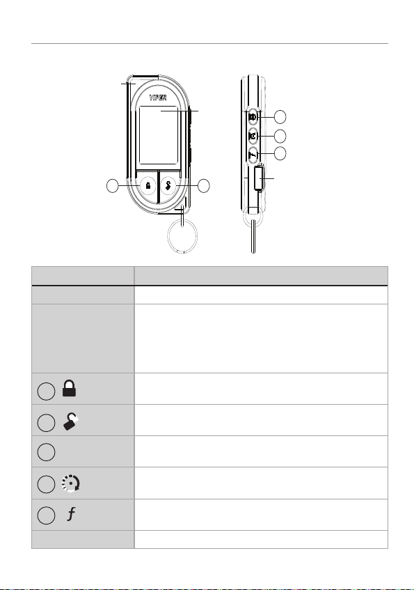
Responder LC3 2-Way
1-800-274-0200
RPN 7752V
IC: 1513A-7752
FCC ID:EZSDEI7752
AUX
AUX
Internal
Antenna
Display
3
4
5
1 2
Feature Description
Internal Antenna Used for transmitting and receiving information
Display Status screen - the upper portion of the display contains status
1
2
3
AUX
4
5
Mini-USB Port The battery charger plugs into this port.
4
icons for the System, Remote Start and Remote Control.
Text field - the lower portion of display - shows the Clock,
or Runtime, as well as Command confirmations, Page messages and programming menus
Press for one second to lock.
Press for one second to unlock.
Press and hold for 5 seconds to activate optional trunk
release or other optional accessory.
Press for one second to activate remote start.
Allows access to programming and modifies operation of
the other buttons.
Mini-USB Port
© 2012 Directed. All rights reserved.

Advanced Remote Control Commands
Refer to the Quick Reference Guide for more information
on advanced remote start commands that are specific to
each vehicle.
Fault Condition Alerts
If, when performing a command, a condition exists that does not
allow activation of a Remote Start feature*, the
remote start error
text and a fault tone will play.
* Remote Start feature not available when the Remote Start status
is incorrect upon receiving the command. Refer to the notes included in the command descriptions that address these faults or
go to Remote Start Error under the Remote Start Features section
for more details.
not available
or
© 2012 Directed. All rights reserved.
5
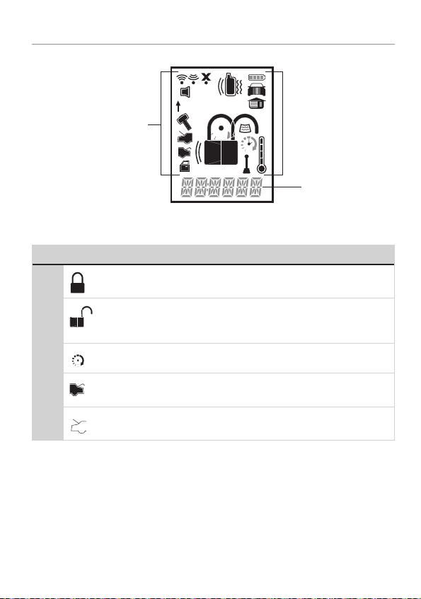
Status Screen Icons
ALL
ALL
ALL
ALL
Status Screen
Icons
The table below describes all the status screen icons.
Icon Description
Locked: The system is Locked.
System Status
Remote Start
Unlocked: The system is Unlocked.
Remote start is active, the engine is running.
On during Aux/Trunk channel activation.
On during Fault Report to indicate the Hood is open.
1
Text Field
6
© 2012 Directed. All rights reserved.
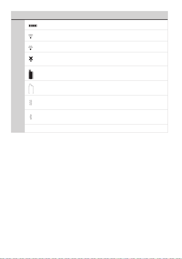
Icon Description
ALL
ALL
ALL
ALL
ALL
ALL
Bars indicate battery level is Full, ¾,½,¼ or Empty.
On while the remote control is transmitting a command.
On while the remote control is receiving a message.
On with Out of Range fault tone to indicate the remote failed to
receive a command confirmation.
Pager on: The remote will wake up to listen for messages.
Pager off: The remote will not wake up to listen for messages.
Remote Control Status
The remote will Vibrate when messages are received.
The remote will emit Beeps and Tones when messages are
received.
Text field
Displays the Clock, Runtime, message text and feature menus.
© 2012 Directed. All rights reserved.
7
Basic Commands
AUX
AUX
AUX
AUX
1
ALL
Remote Start
Press and release
Activates (or if On, deactivates) the remote starter.
The engine and parking lights turn On and the
remote start on
and parking lights turn Off and the
text and tones play, or the engine
remote start off
play to confirm, the Remote Start status icons update. The
will display in the status screen and the text field will display the
Runtime or Clock as programmed. If Remote Start fails to activate,
remote start error
text and a fault tone play.
The runtime on the remote starter is predetermined based on vehicle
application. The remote starter will shut down when the preset runtime
times out or when any shutdown zone becomes active.
Refer to the Quick Reference Guide for more information.
Note
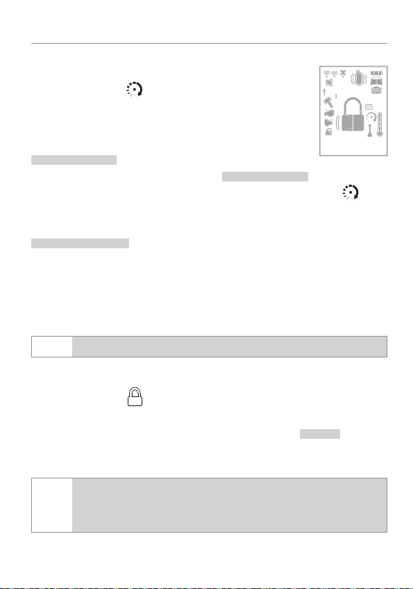
Lock
Press and release
6:30
text and tones
icon
The doors lock and parking lights flash once. The
beeps play to confirm and the System Status Icons update.
If the remote is set to Remote Keyless Entry (RKE), it will dis-
Note
play LOCK/UNLOCK; otherwise, it will display ARMED/
DISARMED.
8
© 2012 Directed. All rights reserved.
armed
text and

Unlock
Press and release
The doors unlock and parking lights flash twice. The
disarm
text and
beeps play to confirm and the system status icons update.
If the remote is set to Remote Keyless Entry (RKE), it will dis-
Note
play LOCK/UNLOCK; otherwise, it will display ARMED/
DISARMED.
AUX/Trunk
Press and hold
The Trunk opens (if connected) when this button is pressed for 5 seconds. The
AUX
trunk
text and tones play to confirm.
© 2012 Directed. All rights reserved.
9

Advanced Commands
AUX
AUX
AUX
Refer to the Quick Reference Guide for more information
on advanced commands that are specific to each vehicle.
Runtime Reset
Press the
Re-starts the remote start runtime counter if remote start is active.
button 1 time and then
.
10
© 2012 Directed. All rights reserved.

Responder LC3 Configuration
AUX
AUX
AUX
AUX
AUX
Operations of the Responder LC3 and how it communicates messages
are set in the configuration Main Menu. The following instructions will
direct you through the available programming options.
Navigating Menus and Options
Navigating menus and features, changing options, and exiting are
performed using the remote control buttons. The following instructions
discuss how to access and configure the settings.
Access Menu Items
1. Press and hold the
once,
main menu
2. Release the
setup remote
is displayed.
3. The Main Menu has been accessed and configuring can begin.
Use the following process to view the Main Menu features, options and settings in the text field. The following actions are commonly used throughout the configuration operation.
button for 8 seconds, the remote will beep
is displayed.
button to display the Main Menu item list,
• Press the
AUX
or
that is displayed in the text field.
• Press the
button to choose the feature in the text field and
view its options. Press it when the desired feature or option
is in the text field to set it as the new setting.
4. To exit configuration: use the
© 2012 Directed. All rights reserved.
buttons to change the feature or option
or
buttons.
11

Remote Pairing
The following instruction will step you through the remote pairing operation.
1. Perform the steps under Access menu items section to access the
Pair Remote mode.
2. When the remote beeps 3 times and
remote is ready to pair.
3. Within 5 seconds press and release 1 time the Integrated Programming Button (IPB) on the XL202.
4. Within 5 seconds, press and hold IPB on the XL202. The status
LED will flash one time to confirm the system is ready for remote
pairing.
5. Press and hold the
to confirm successful pairing.
button the remote will emit several tones
success
remote returns to the main menu.
6. Release the IPB on the XL202.
failed
Note
will be displayed and the remote will stay in the
pair mode in case of an unsuccessful pairing. Check the
system status and try again.
Consult the installation center for the location of the XL202
Note
or refer to dealer for programming.
pair
is displayed the
is displayed and the
Remote Features (Main Menu)
The following Main Menu list of features is available for configuration
of the remote control.
12
© 2012 Directed. All rights reserved.

Setup Remote menu
AUX
Keypad Lock
Options:
When
mand when pressed. When set to
lock after a 20 second lapse between buttons presses to prevent
unintentional operations. If a button is pressed when locked a
fault tone plays as an alert followed by unlock instructions in the
text field. To unlock the buttons, press the
the
in the text field, a command can now be performed.
Page Mode
Options:
Paging is how the Responder LC3 remote monitors your system’s
messages.
Off after 72 hours if the remote control is not used during this
period. Just press any button to resume system monitoring. When
set to
from the system. When set to
remote start or alarm trigger pages.
Page Alert
Options:
off,auto
off
, the buttons do not lock and always perform a com-
auto
, the remote buttons
button followed by
button. The unlock tones play and
power save,off,on
power save
on
it wakes up every few seconds to listen for pages
tone vibe,tone,vibe,screen only
extends battery life by turning Paging
off
it does not wake up to receive
ready
is displayed
There are several ways for the Responder LC3 to alert you when
it has received a message from the system.
tone vibe
mote. Select
© 2012 Directed. All rights reserved.
will alert by both emitting tones and vibrating the re-
tone
to be alerted by tones that are unique for
13

each message. Select
alert you with a gentle vibration, or select
vibe
and the Responder LC3 will silently
screen only
when you
don’t want to be interrupted.
Remote Start Info
Options:
runtime,temp,clock
The text field can be set to display the information you prefer
during remote start.
runtime
: Remote Start Runtime,
available on this system), or the
clock
will be displayed in the
temp
(not
text field while Remote Start is on.
Runtime Alert (Not available on this system)
Options:
on,off
Car 2
Options:
Turns
for
off,on,home
off
or on, 2 car operation from the remote. The option
home
is not available.
Screen Color
Options:
The status screen backlighting can be
off,white,lt grn,violet,aqua,red,green,blue
off
, or will illuminate
with a selected color during output when set to one of the option
colors.
Temp Unit (Not available on this system)
Options:
14
f,c
© 2012 Directed. All rights reserved.

Button Beep
Options:
on,off
When set to on, the remote will emit a beep as confirmation
of a button press. When set to
off
, beeps are not emitted for
button presses.
System Type
Options:
Note
sec,rke
If the remote is set to Remote Keyless Entry (RKE), it will
display LOCK/UNLOCK; otherwise, it will display
ARMED/DISARMED.
Clock Set
Options:
hour,min
Review
Displays firmware version
Exit
Exits and returns to the main menu
Pair Remote
See Remote Pairing section on page 12.
© 2012 Directed. All rights reserved.
15

Demo Mode
AUX
AUX
Demo Mode plays a pre-selected group of animations as a demonstration tool to show friends or family. Running Demo mode shortens
the battery life over time if used excessively
single silent
•
: The remote will display a selection of icons on
the status screen without beeps and tones then stop.
single sound
•
: The remote will display a selection of icons on
the status screen with beeps and tones then stop.
loop silent
•
: The remote will display a selection of icons on
the status screen without beeps and tones in an endless loop until
the battery charger is disconnected.
loop sound
•
: The remote will display a selection of icons on
the status screen with beeps and tones in an endless loop until the
battery charger is disconnected.
Loop Silent and Loop Sound are not available and will not
Note
appear in the Demo Mode menu unless the battery charger
is connected.
Power Off
When an extended period of non-operation is anticipated, turning the
power off will preserve the battery charge. Press the
power off
is displayed. The status screen icons clear as the power
off tones play, the remote is turned off.
button while
To turn the remote on, Press and hold the
button for 3 seconds,
the status screen icons refresh as the power on tones play. The remote
also turns itself on and begins charging when the battery charger is
connected.
16
© 2012 Directed. All rights reserved.

Exit
AUX
To return to normal operation, press the
played.
button while EXIT is dis-
© 2012 Directed. All rights reserved.
17

Remote Start Features
Refer to the Quick Reference Guide for more information on
remote start features that are specific to each vehicle.
Disabling Remote Start
Remote start can be disabled by moving the Toggle Switch to the Off
position. If remote start is attempted while Off, the engine will not start.
Move the switch back to the On position to resume normal operation.
Consult the installation center for the location of Toggle
Note
switch.
18
© 2012 Directed. All rights reserved.

Remote and System Operations
ALL
Out of Range
Each time a command is performed the remote will expect a command confirmation from the system. If a command confirmation is not
received the out-of-range icon (
alert.
No Remote Output
Occasionally when a command is performed the remote may not
generate a command confirmation output or Out of Range output.
This indicates that the system received the command but it was an
incomplete command (e.g. Aux button pressed too short to activate
the trunk release) or it was an illegal message (e.g. the command
was corrupted due to local RF interference). These are temporary normal functions of the system and remote, perform the command again
within 10 seconds to return to normal operation.
) and a fault tone will play as an
© 2012 Directed. All rights reserved.
19

1-Way Companion Remote Control
1-800-274-0200
RPN 7152P
IC: 1513A-7152
FCC ID:EZSDEI7152
BATTERY: CR2032
8
9
1
2
3
4
5
Transmit
LED
Internal
Antenna
AUX
AUX
Internal
Antenna
Transmit
LED
Feature Description
Internal Antenna Used for transmitting information
Transmit LED
1
2
3
4 AUX
5
Transmit LED flashes when transmitting information.
Press for one second to lock.
Press for one second to unlock.
Press for one second to activate remote start.
Press and hold for 5 seconds to activate optional trunk
release or other optional accessory.
Allows access to programming and modifies operation of
the other buttons.
1
2
AUX
3
4
5
20
© 2012 Directed. All rights reserved.

Using the 1-Way Companion Remote
AUX
AUX
AUX
AUX
AUX
The companion 1 way remote commands the system features as
shown in the previous table, but without the message display of the
Responder LC3 remote. Parking light flashes is used to indicate that a
command has been received and activated as described in the Basic
and Advanced command sections.
Accessing Commands
Similar to the Responder LC3 remote, Basic commands are performed
when a command button is pressed directly. To perform Advanced
Commands press the
x4 in the table for example implies pressing
button 1 to 4 times to access function levels,
4 times. The
LED flashes in groups for a few seconds to indicate the level. Press
the desired command button while the LED is flashing to perform the
command.
Button Auto Lock
When On, the remote control buttons lock if more than 20 seconds
lapses between button presses. If a button is pressed when locked,
a fault tone is emitted. To unlock the buttons; press the
lowed by the
button, the buttons unlock and tones play to confirm.
button fol-
Programming
To enter; hold the
beep and turns the LED on, the programming main menu has been
accessed.
button for 8 seconds, the remote emits one long
© 2012 Directed. All rights reserved.
21

To exit; press and release the
AUX
AUX
AUX
button to go back and repeat to exit.
1 short and 1 long beep is emitted for each step back, the LED turns
off when programming is exited.
Remote Features Menu
Press and release the
button, 2 LED flashes and beeps indi-
cate the remote features menu is accessed and can be set. Press
buttons indicated below, 1 beep and flash turns the feature on, 2
beeps and flashes turns the feature off.
• Autolock feature: Press
• Remote Beeps: Press
to turn on/off.
to turn on/off.
Remote Learning
Press the
button,3 LED flashes and beeps indicates the re-
mote is ready to program to the system.
Per the instruction in Remote Pair under the Main Menu section of
this guide, following step 4. Press and hold the
button, there
is no confirmation of pairing completed for this remote control.
22
© 2012 Directed. All rights reserved.

Battery Information (1-Way)
1-800-274-0200
RPN 7152P
IC: 1513A-7152
FCC ID:EZSDEI7152
BATTERY: CR2032
+
Battery
Cover
Battery
Clip
Rear View
1 2
The 1-way companion remote is powered by one 3V coin cell lithium
battery (PN CR-2032) that will last approximately one year under
normal use.
Battery Replacement
Rear View
1 2
Battery
Battery
Cover
and slide back into housing until securely latched. The remote control
is now ready for use.
Clip
1. Using a small flat narrow object,
push latch down towards battery tray
while gently prying the tray outwards
from both ends until released. Remove the tray from the remote control
housing.
+
2. While observing the correct polarity, replace the old battery with a
new one. Seat battery flush into tray
© 2012 Directed. All rights reserved.
23

Battery Information (Responder LC3)
The Responder LC3 remote control is powered by an internal rechargeable battery that can be serviced only through an authorized
Directed Electronics dealer. The information and precautions in this
section can help maximize your battery’s life and usage in providing
your Responder LC3 remote control with many years of trouble free
operation.
The battery information for the 1-way companion remote control can
be found in the 1-way Companion Remote Control section of this
manual.
Warnings! NEVER connect the supplied AC adapter
to products other than the Responder LC3 remote control. It is a high current device designed specifically for
rapid charging of the Responder LC3 battery and may
cause severe damage or explosion when connected to
any other products.
Charging the battery when the temperature is below
32°F (0°C) or above 113°F (45°C) may cause severe
battery damage and/or reduce battery life. Avoid
placing the remote control in areas exposed to extreme cold or heat (direct sunlight) when charging the
battery.
Low Battery
After a command is performed the Responder LC3 and 1-way companion remote controls check their battery level and, when the level
24
© 2012 Directed. All rights reserved.

requires attention, will begin generating alerts. Once the alerts begin
they will continue to command the system for several days but should
be charged at the earliest opportunity or failure to control the system
may occur.
Low Battery Alerts
After performing a command,
on the Responder LC3 remote to indicate the battery needs to be
charged.
lowbat
and several beeps play
Important
To preserve power at critically low battery levels the
Responder LC3 turns the pager off and stops receiving
messages from the system. It will continue to command
the system until the battery can be charged.
Battery Life
The Responder LC3 remote control has many features that make it one
of the most unique remote controls on the market today, including superior long range communication with the system. The default feature
settings provide for excellent battery charge duration. However, to
maximize this duration between charges, the following suggestions
will help:
• Turn the remote Off: When not in use and/or out of range of the
vehicle the remote can be turned off in the Main menu.
• Turn Paging off: The remote will not wake up to check for messages with Paging off in the Setup Remote menu.
• Turn Beeps off: The Button beeps can be turned off in the Setup
Remote menu. The command beeps still play normally.
© 2012 Directed. All rights reserved.
25

Battery Disposal
Directed Electronics cares about the environment. If you
need to dispose of the battery, please do so in accordance
with your municipal requirements for battery disposal.
26
© 2012 Directed. All rights reserved.

Government Regulations
This device complies with Part 15 of FCC rules. Operation is subject to the following
two conditions: (1) This device may not cause harmful interference, and (2) This device
must accept any interference received, including interference that may cause undesirable
operation.
This equipment has been tested and found to comply with the limits for a class B digital
device, pursuant to Part 15 of the FCC Rules. These limits are designed to provide
reasonable protection against harmful interference in a residential installation. This equipment generates and can radiate radio frequency energy and, if not installed and used
in accordance with the instruction manual, may cause harmful interference to radio communications. However, there is no guarantee that interference will not occur in a particular
installation. If this equipment does cause harmful interference to radio or television, which
can be determined by turning the equipment OFF and ON, the user is encouraged to try
to correct the interference by one or more of the following measures:
• Reorient or relocate the receiving antenna.
• Increase the separation between the equipment and receiver.
• Connect the equipment into an outlet on a circuit different from that to which the
receiver is connected.
• Consult the dealer or an experienced radio / TV technician for help.
Remote Controls
To satisfy FCC RF exposure compliance requirements, this device should be used in
hand-held, hand operated configurations only. The device and its antenna must maintain
a separation distance of 20 cm or more from the person’s body, except for the hand
and wrists, to satisfy RF exposure compliance. This device is designed to be used in a
person’s hands and its operating configurations do not support normal transmissions while
it is carried in pockets or holsters next to a person’s body.
Control Center
To satisfy FCC RF exposure compliance requirements, the device and its antenna must
maintain a separation distance of 20 cm or more from the person’s body, except for the
hand and wrists, to satisfy RF exposure compliance.
© 2012 Directed. All rights reserved.
27

This device complies with the Industry Canada Radio Standards Specification RSS 210.
Its use is authorized only on a no-interference, no-protection basis; in other words, this
device must not be used if it is determined that it causes harmful interference to services
authorized by IC. In addition, the user of this device must accept any radio interference
that may be received, even if this interference could affect the operation of the device.
Changes or modifications not expressly approved by the party responsible
for compliance could void the user’s authority to operate this device.
28
© 2012 Directed. All rights reserved.

Warning! Safety First
Please read the safety warnings below before proceeding. Improper use of the
product may be dangerous or illegal.
Installation
Due to the complexity of this system, installation of this product must only be performed
by an authorized Directed dealer. If you have any questions, ask your retailer or contact
Directed directly at 1-800-753-0600.
Remote Start Capable
When properly installed, this system can start the vehicle via a command signal from
the remote control transmitter. Therefore, never operate the system in an enclosed area
or partially enclosed area without ventilation (such as a garage). When parking in an
enclosed or partially enclosed area or when having the vehicle serviced, the remote start
system must be disabled using the installed menu wheel. It is the user’s sole responsibility
to properly handle and keep out of reach from children all remote control transmitters
to assure that the system does not unintentionally remote start the vehicle. THE USER
MUST INSTALL A CARBON MONOXIDE DETECTOR IN OR ABOUT THE LIVING AREA
ADJACENT TO THE VEHICLE. ALL DOORS LEADING FROM ADJACENT LIVING AREAS
TO THE ENCLOSED OR PARTIALLY ENCLOSED VEHICLE STORAGE AREA MUST AT
ALL TIMES REMAIN CLOSED. These precautions are the sole responsibility of the user.
Interference
All radio devices are subject to interference which could affect proper performance.
Upgrades and Batteries
Any upgrades to this product and/or installation of batteries must be performed by an
authorized dealer. Do not attempt to perform any unauthorized modifications to this
product.
Water/Heat Resistance
This product is not designed to be water and/or heat-resistant. Please take care to keep
this product dry and away from heat sources. Any damage from water or heat will void
the warranty.
© 2012 Directed. All rights reserved.
29

Limited Lifetime Consumer Warranty
Directed Electronics. (“Directed”) promises to the original purchaser to repair or replace
(at Directed’s election) with a comparable reconditioned model any Directed unit (hereafter the “unit”), excluding without limitation the siren, the remote transmitters, the associated
sensors and accessories, which proves to be defective in workmanship or material under
reasonable use during the lifetime of the vehicle provided the following conditions are
met: the unit was purchased from an authorized Directed dealer, the unit was professionally installed and serviced by an authorized Directed dealer; the unit will be professionally
reinstalled in the vehicle in which it was originally installed by an authorized Directed
dealer; and the unit is returned to Directed, shipping prepaid with a legible copy of the
bill of sale or other dated proof of purchase bearing the following information: consumer’s
name, telephone number and address; the authorized dealers name, telephone number
and address; complete product description, including accessories; the year, make and
model of the vehicle; vehicle license number and vehicle identification number. All components other than the unit, including without limitation the siren, the remote transmitters
and the associated sensors and accessories, carry a one-year warranty from the date of
purchase of the same. ALL PRODUCTS RECEIVED BY DIRECTED FOR WARRANTY REPAIR
WITHOUT PROOF OF PURCHASE FROM AN AUTHORIZED DEALER WILL BE DENIED.
This warranty is non-transferable and is automatically void if: the unit’s date code or serial
number is defaced, missing or altered; the unit has been modified or used in a manner
contrary to its intended purpose; the unit has been damaged by accident, unreasonable
use, neglect, improper service, installation or other causes not arising out of defects in
materials or construction. The warranty does not cover damage to the unit caused by
installation or removal of the unit. Directed, in its sole discretion, will determine what constitutes excessive damage and may refuse the return of any unit with excessive damage.
TO THE MAXIMUM EXTENT ALLOWED BY LAW, ALL WARRANTIES, INCLUDING
BUT NOT LIMITED TO EXPRESS WARRANTY, IMPLIED WARRANTY, WARRANTY
OF MERCHANTABILITY, FITNESS FOR PARTICULAR PURPOSE AND WARRANTY OF
NON-INFRINGEMENT OF INTELLECTUAL PROPERTY, ARE EXPRESSLY EXCLUDED;
AND DIRECTED NEITHER ASSUMES NOR AUTHORIZES ANY PERSON OR ENTITY
TO ASSUME FOR IT ANY DUTY, OBLIGATION OR LIABILITY IN CONNECTION
WITH ITS PRODUCTS. DIRECTED DISCLAIMS AND HAS ABSOLUTELY NO LIABILITY
FOR ANY AND ALL ACTS OF THIRD PARTIES INCLUDING ITS AUTHORIZED
DEALERS OR INSTALLERS. DIRECTED SECURITY SYSTEMS, INCLUDING THIS UNIT,
ARE DETERRENTS AGAINST POSSIBLE THEFT. DIRECTED IS NOT OFFERING A
GUARANTEE OR INSURANCE AGAINST VANDALISM, DAMAGE OR THEFT OF THE
AUTOMOBILE, ITS PARTS OR CONTENTS; AND HEREBY EXPRESSLY DISCLAIMS ANY
LIABILITY WHATSOEVER, INCLUDING WITHOUT LIMITATION, LIABILITY FOR THEFT,
DAMAGE AND/OR VANDALISM. THIS WARRANTY DOES NOT COVER LABOR
30
© 2012 Directed. All rights reserved.

COSTS FOR MAINTENANCE, REMOVAL OR REINSTALLATION OF THE UNIT OR
ANY CONSEQUENTIAL DAMAGES OF ANY KIND. IN THE EVENT OF A CLAIM
OR A DISPUTE INVOLVING DIRECTED OR ITS SUBSIDIARY, THE VENUE SHALL BE
SAN DIEGO COUNTY IN THE STATE OF CALIFORNIA. CALIFORNIA STATE LAWS
AND APPLICABLE FEDERAL LAWS SHALL APPLY AND GOVERN THE DISPUTE. THE
MAXIMUM RECOVERY UNDER ANY CLAIM AGAINST DIRECTED SHALL BE STRICTLY
LIMITED TO THE AUTHORIZED DIRECTED DEALER’S PURCHASE PRICE OF THE UNIT.
DIRECTED SHALL NOT BE RESPONSIBLE FOR ANY DAMAGES WHATSOEVER,
INCLUDING BUT NOT LIMITED TO, ANY CONSEQUENTIAL DAMAGES, INCIDENTAL
DAMAGES, DAMAGE TO VEHICLE, DAMAGES FOR THE LOSS OF TIME, LOSS OF
EARNINGS, COMMERCIAL LOSS, LOSS OF ECONOMIC OPPORTUNITY AND THE
LIKE. NOTWITHSTANDING THE ABOVE, THE MANUFACTURER DOES OFFER A
LIMITED WARRANTY TO REPLACE OR REPAIR THE CONTROL MODULE SUBJECT TO
THE CONDITIONS AS DESCRIBED HEREIN. THIS WARRANTY IS VOID IF THE UNIT
HAS NOT BEEN PURCHASED FROM DIRECTED, OR AN AUTHORIZED DIRECTED
DEALER, OR IF THE UNIT HAS BEEN DAMAGED BY ACCIDENT, UNREASONABLE
USE, NEGLIGENCE, ACTS OF GOD, NEGLECT, IMPROPER SERVICE, OR OTHER
CAUSES NOT ARISING OUT OF DEFECT IN MATERIALS OR CONSTRUCTION.
Some states do not allow limitations on how long an implied warranty will last or the
exclusion or limitation of incidental or consequential damages. This warranty gives you
specific legal rights and you may also have other rights that vary from State to State.
This warranty is only valid for sale of product(s) within the United States of America and
in Canada. Product(s) sold outside of the United States of America or Canada are sold
“AS-IS” and shall have NO WARRANTY, express or implied.
For further details relating to warranty information of Directed products, please visit the
support section of Directed’s website at: www.directed.com.
This product may be covered by a Guaranteed Protection Plan (“GPP”). See your
authorized Directed dealer for details of the plan or call Directed Customer Service at
1-800-876-0800.
(920-10011-01 2011-06)
Additional information can be found at:
www.xpresskit.com
www.directechs.com
© 2012 Directed. All rights reserved.
31

32
© 2012 Directed. All rights reserved.
 Loading...