

Page 1
Models 608, 1258, and 150S
1/4-lnch
Streaming Cartridge Tape Drive
.
,
Theory
of
Operation
and
Maintenance
Manual
~J!YE'
____________
---1
Page 2
Viper®
SCSI
Models 60S, 125S, and 150S
1/4-lncl1
Streaming Cartridge Tape Drive
Theory
of
Operation
and
Maintenance
Manual
Page 3
I
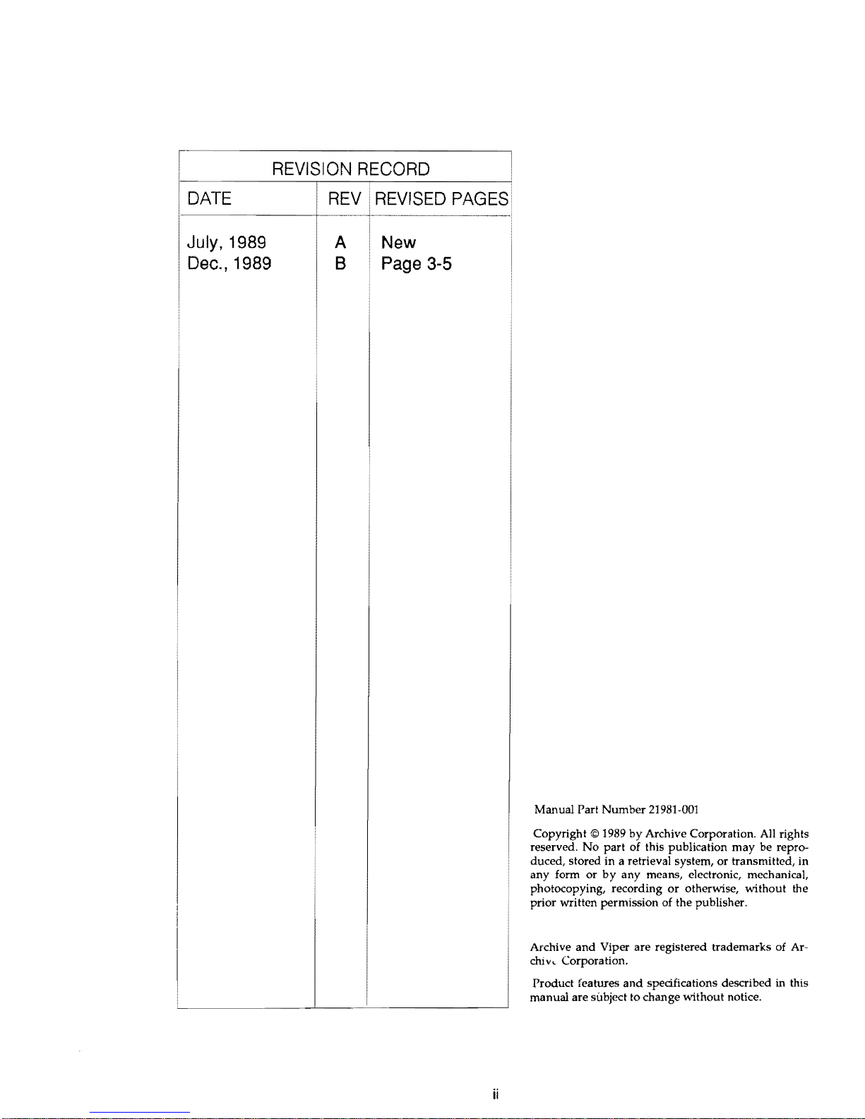
DATE
July, 1989
Dec., 1989
REVISION
RECORD
REV
REVISED
PAGES
A
B
New
Page
3-5
ii
Manual Part
Number
21981-001
Copyright © 1989
by
Archive Corporation. All rights
reserved.
No
part
of this publication
may
be reproduced, stored in a retrieval system, or transmitted, in
any form
or
by
any means, electronic, mechanical,
photocopying, recording
or
otherwise, without the
prior written permission of the publisher.
Archive
and
Viper are registered trademarks of Ar-
chive
Corporation.
Product features
and
specifications described in this
manual are subject to change without notice.
Page 4
VIPER SCSI 60, 125 & 150 THEORY
OF
OPERA TION
AND
MAINTENANCE
PREFACE
Archive Viper tape drives are manufactured to ensure high performance in a
1/
4-inch
streaming tape drive. Viper enhanced mechanics
and
performance features include
an
embed-
ded
controller in a half-high
5-1/4
inch form factor drive.
The
manual
contains detailed technical information about Viper SCSI (Small Computer
Systems Interface) tape drives.
SCSI technology provides a flexible environment by allowing
up
to eight devices to be daisy chained. Archive Viper drives conform
to
ANSI Specification
X3.31
and
QIC tape format standards.
Archive's commitment to high quality
and
advanced technology
mean
Viper tape drives are
efficient
and
reliable for
data
backup in varied installations
and
environments.
iii
Page 5
VIPER SCSI 60, 125 & 150 THEORY
OF
OPERA TION
AND
MAINTENANCE
CONTENTS
Chapter 1
Introduction ...............................................................................................................................
1-1
1.1
Overview ...............................................................................................................................
1-1
1.2 Viper Capacities ...................................................................................................................
1-1
1.3 PhYSical Description ...........................................................................................................
1-1
1.4 System Configurations ....................................................................................................... 1-2
1.5 Viper Drive Models ............................................................................................................
1-3
1.6
About This Manual .............................................................................................................. 1-4
Chapter 2
Specifications ...........................................................................................................................
2-1
2.1
Overview...... ....... ................... .......
....
............................ ............................... ................. ......
2-1
2.2 Physical Specifications ......................................................................................................
2-1
2.3
Power
Requirements ......................................................................................................... 2-2
2.3.1
Power
Connector ....................................................................................................... 2-2
2.4 Drive Performance Specifications ................................................................................... 2-3
2.5
Environmental Specifications ...............
....
........... ........... ............... ............. ..................... 2-4
2.6
Data Cartridge Specifications .......................................................................................... 2-4
2.6.1
Model
60S
........ ....... ......................
....
......
........... ................... ................ ................ ..... 2-4
2.6.2 Model
125S
................................................................................................................
2-5
2.6.3 Model
150S
................................................................................................................
2-5
2.7 Regulatory Compliance ....................................................................................................
2-5
2.8
ANSI
X3.131
Conformance Statement ............................................................................ 2-6
Chapter 3
Installation .................................................................................................................................
3-1
3.1
Introduction ..........................................................................................................................
3-1
3.2 Guidelines
and
Cautions ............................................................. .....................................
3-1
3.3 Unpacking
and
Inspection...... ................................... ........... ................... .................. ......
3-1
3.4 Installation .......................................................................................................................... 3-2
3.5 Internal Viper Drives ........................................................................................................... 3-2
3.5.1
Mounting Screws ...................................................................................................... 3-2
3.5.2 Connectors ................................................................................................................. 3-3
3.5.3 Jumper Configuration
.... ....
...................... .......
....
......... ........
.....
...... ........................ 3-4
3.5.4 Operational Mode .................................................................................................... 3-4
3.5.5 Parity Enable ............................................................................................................. 3-4
3.5.6 Drive Identification .................................................................................................. 3-5
3.5.7 Selectable Buffer Disconnect .................................................................................... 3-5
3.6
Connecting External Vipers ............................................................................................... 3-6
3.6.1
SCSI Drive Identification Switch ............................................................................. 3-7
v
Page 6
VIPER SCSI 60, 125 & 150 THEORY
OF
OPERATION AND MAINTENANCE
Chapter 4
Interface ....................................................................................................................................
4-1
4.1
Overview.... .................................
.... ....
......... ....................................... .......................... ...... 4-1
4.1.1
ANSI SCSI Bus Standards.......... ............................................ ............. .................... 4-1
4.1.2
Signal Notation Conventions ................................................................................. 4-1
4.2
SCSI
Bus Connector Signals ............................................................................................. 4-2
4.3
Signal Descriptions
..
....
........................
....
............. .............. .....................
.....
.................
....
4-3
4.4
Command
Set Description.. ................. ........... ............................ ........... ................ .......... 4-4
4.5
SCSI
Bus Protocol............... ........
...
................. ....... .....................
...
................... ....... ........... 4-5
4.6
Waiting
and
Control Phases ............................................................................................. 4-6
4.6.1
Nonarbitrating Systems ........................................................................................... 4-6
4.6.2
Arbitrating Systems ................................................................................................. 4-6
4.7
Selection
and
Reselection Phases .............................. ............................ .......................... 4-9
4.8
Information Transfer Phases ........................................................................................... 4-10
4.8.1 Asynchronous Data Transfer ................................................................................ 4-10
4.8.1.1 Transfer from Target
to
Initiator ................................................................. 4-11
4.8.1.2
Transfer from Initiator to Target ................................................................. 4-12
4.9
Command
Phase ............................................................................................................... 4-13
4.10 Data Phase ........................................................................................................................ 4-13
4.10.1 Data-In Phase ......................................................................................................... 4-13
4.10.2 Data-Out Phase ...................................................................................................... 4-13
4.11
Status Phase ..................................................................................................................... 4-13
4.12
Message Phase ................................................................................................................. 4-13
4.12.1
Message-In Phase .................................................................................................. 4-13
4.12.2
Message-Out Phase ............................................................................................... 4-14
4.13
Con1mand Descriptor Block .......................................................................................... 4-14
4.14
SCSI
Message Descriptions
and
Definitions ............................................................... 4-16
4.15
SCSI
Status Code Descriptions
and
Definitions ......................................................... 4-19
4.16
Attention Condition ....................................................................................................... 4-21
4.17
Reset Condition ............................................................................................................... 4-21
4.18
Unit Attention Condition .............................................................................................. 4-21
4.19
Buffered Mode ................................................................................................................. 4-22
4.20 Imn1ediate Function ....................................................................................................... 4-22
4.21
Residual Length Function ............................................................................................. 4-22
4.22
Disconnect/Reconnect Function .................................................................................. 4-24
4.23
SCSI Memory Address Pointers ................................................................................... 4-25
4.23.1
Current Data Pointers ........................................................................................... 4-25
4.23.2
Saved Data Pointers .............................................................................................. 4-25
4.24
Early Warning Function ................................................................................................ 4-25
4.25
Error Reporting ............................................................................................................... 4-26
4.25.1
Soft Errors ............................................................................................................... 4-26
4.25.2
Hard
Errors ............................................................................................................ 4-26
4.26
SCSI
Bus Phase Timing .................................................................................................. 4-26
vi
Page 7
VIPER SCSI 60. 125 & 150 THEORY
OF
OPERA TlON AND MAINTENANCE
Chapter 5
Viper
SCSI
Commands ............................................................................................................
5-1
5.1
Introduction
.........................................................................................................................
5-1
5.2
Descriptor
Block .................................................................................................................. 5-2
5.2.1
Command
Descriptor Block
Format
...................................................................... 5-2
5.2.2
Command
Descriptor
Block Field Descriptions ................................................... 5-2
5.2.3 Flag
and
Link Bit Descriptions ................................................................................ 5-3
5.3
TEST
LTNIT
READY
(OOh)
.................................................................................................. 5-4
5.3.1
TEST
UNIT
READ
Command
Descriptor Block .................................................. 5-4
5.3.2
Completion
Status ..................................................................................................... 5-4
5.4 REWIND
(Olh) .................................................................................................................... 5-5
5.4.1 REWIND
command
Descriptor Block ................................................................... 5-5
5.4.2
Command
Descriptor Block Field DescriAtion .................................................... 5-5
5.4.3
Completion
Status
..................................................................................................... 5-5
5.5
REQUEST BLOCK ADDRESS (02h) ................................................................................ 5-6
5.5.1
REQUEST BLOCK ADDRESS
Command
Descriptor Block .............................. 5-6
5.5.2
Command
Descriptor
Block Field .......................................................................... 5-6
5.5.3
REQUEST BLOCK ADDRESS Data
Format
......................................................... 5-6
5.5.4
REQUEST BLOCK ADDRESS Data Field Description ........................................ 5-7
5.5.5
Completion
Status ..................................................................................................... 5-7
5.6
REQUEST SENSE ( 03h ) ...................................................................................................
5-S
5.6.1 REQUEST SENSE
Command
Descriptor Block ...................................................
5-S
5.6.2
Command
Descriptor Block Field Description ....................................................
5-S
5.6.3
Extended
Sense
Data
Format .................................................................................. 5-9
5.6.4
Extended
Sense Data Field Descriptions ............................................................. 5-10
5.6.4
Extended
Sense
Data
Field Descriptions
Continued
..........................................
5-11
5.6.5 Priority
and
Definition of Sense Keys ................................................................... 5-12
5.6.6
Completion
Status
.................................................................................................... 5-13
5.7 READ
BLOCK LIMITS (05h) ........................................................................................... 5-14
5.7.1 READ
BLOCK LIMITS
Command
DeSCriptor Block ......................................... 5-14
5.7.2
Command
Descriptor Block Field Descriptions .................................................. 5-14
5.7.3 READ
BLOCK LIMITS Data Format.. ................................................................... 5-14
5.7.4
Completion
Status .................................................................................................... 5-15
5.8 READ (aSh) ......................................................................................................................... 5-16
5.8.1 READ
Command
Descriptor Block ....................................................................... 5-16
5.8.2
Command
Descriptor Block Field Descriptions .................................................. 5-16
5.S.3 READ
Command
Description ................................................................................ 5-16
5.8.3.1
End
of
Data ...................................................................................................... 5-17
5.S.3.2
Filen·lark., ....................................................................................................... 5-17
5.8.3.3 Transfer Length
Satisfied .............................................................................. 5-17
5.8.3.4
End
of
Tape
(EOT) .......................................................................................... 5-17
5.8.3.5 Unrecoverable
Data
Error
............................................................................. 5-17
5.8.4
Completion
Status .................................................................................................... 5-18
5.9 WRITE
(OAh)
...................................................................................................................... 5-19
5.9.1 WRITE
Command
Descriptor Block ..................................................................... 5-19
vii
Page 8
VIPER
SCSI
60,
125
& 150 THEORY
OF
OPERA TlON
AND
MAINTENANCE
5.9.2
Command
Descriptor Block Field Descriptions .................................................. 5-20
5.9.3 Completion Status .................................................................................................... 5-20
5.9.3 Completion Status Continued ...............................................................................
5-21
5.10 SEEK BLOCK
(OCh)
......................................................................................................... 5-22
5.10.1
SEEK BLOCK
Command
Descriptor Block ....................................................... 5-22
5.10.2
Command
Descriptor Block Field Descriptions ................................................ 5-22
5.10.3 Completion Status .................................................................................................. 5-23
5.11
WRITE FILEMARKS (10h) ............................................................................................. 5-24
5.11.1 Write Filemark
Command
Descriptor Block ..................................................... 5-24
5.11.2
Command
Descriptor Block Field Descriptions ................................................ 5-24
5.11.3 Completion
Status .................................................................................................. 5-25
5.12
SPACE (11h) ..................................................................................................................... 5-26
5.12.1
SPACE
Command
Descriptor Block ................................................................... 5-26
5.12.2
Command
DeSCriptor Block Field Descriptions ................................................ 5-27
5.12.3 Space-by-Count Functions .................................................................................... 5-27
5.12.4
Space
by
Position Functions ................................................................................. 5-28
5.12.5 Completion
Status .................................................................................................. 5-28
5.13 INQUIRY (12h) .................................................................................................................
5-30
5.13.1
INQUIRY
command
Descriptor Block ................................................................ 5-30
5.13.2
Command
Descriptor Block Field Description .................................................. 5-30
5.13.3 INQUIRY
Command
Data Format ......................................................................
5-31
5.13.4 INQUIRY
Command
Data Field Descriptions ..................................................
5-31
5.13.5 Completion Status .................................................................................................. 5-32
5.14 VERIFY (13h) .........................................................................................
..,
......................... 5-33
5.14.1
VERIFY
Command
Descriptor Block .................................................................. 5-33
5.14.2
Command
Descriptor Block Field ....................................................................... 5-33
5.14.3 Con1pletion
Status .................................................................................................. 5-34
5.15 RECOVER BUFFERED DATA
04h)
............................................................................. 5-35
5.15.1
RECOVER BUFFERED DATA
Command
Descriptor Block .......................... 5-35
5.15.2
Command
Descriptor Block Field Descriptions ................................................ 5-35
5.15.3 Completion Status .................................................................................................. 5-36
5.16 MODE SELECT (ISh) .................................................................................... : ................. 5-37
5.16.1
MODE SELECT
Command
Descriptor Block .................................................... 5-37
5.16.2
Command
Descriptor Block Field Description .................................................. 5-37
5.16.3 Parameter List
Header
Format ............................................................................. 5-37
5.16.4 Parameter List
Header
Field Descriptions ......................................................... 5-38
5.16.5 Parameter
List-Block
DeSCriptor ....................................................................... 5-38
5.16.6 Parameter
List-Block
Descriptor Field Descriptions ...................................... 5-39
5.16.7 Paranleter
List-Block
Descriptor Field Descriptions ...................................... 5-40
5.16.8 COlnpletion Status ..................................................................................................
5-41
5.17
RESERVE
UNIT (16h) ..................................................................................................... 5-42
5.17.1
RESERVE
UNIT
Command
Descriptor Block ................................................... 5-42
5.17.2
Command
Descriptor Block Field Descriptions ................................................ 5-43
5.17.3 Completion
Status .................................................................................................. 5-43
viii
Page 9
VIPER
SCSI
60, 125 & 150 THEORY
OF
OPERA TION
AND
MAINTENANCE
5.18 RELEASE UNIT (17h) ..................................................................................................... 5-44
5.18.1
RELEASE UNIT
Command
Descriptor Block ................................................... 5-44
5.18.2
Command
Descriptor Block Field Descriptions ................................................
5-44
5.18.3 Completion Status .................................................................................................. 5-45
5.19
COpy
(18h) ....................................................................................................................... 5-46
5.19.1
Command
Descriptor Block .................................................................................
5-46
5.19.2
Command
Descriptor Block Field Description .................................................
5-46
5.19.3
COpy
Command
Description .............................................................................. 5-46
5.19.4 COPY Parameter List
Header
Block ................................................................... 5-47
5.19.5 Parameter List
Header
Block Field Descriptions ..............................................
5-48
5.19.6
D/
A to SEQ Segment Descriptor ......................................................................... 5-48
5.19.6.1
D/
A to SEQ Segment Descriptor Block .................................................... 5-49
5.19.6.2
D/
A to SEQ Segment Descriptor Field Descriptions .............................. 5-49
5.19.7 SEQ to
D/
A Segment Descriptor .........................................................................
5-50
5.19.7.1 SEQ to
D/
A Segment Descriptor Block .................................................... 5-50
5.19.7.2 SEQ to
D/
A Segment Descriptor Field
~escriptions
..............................
5-51
5.19.8 SEQ to SEQ Segment Descriptor ..........................................................................
5-51
5.19.8.1 SEQ to SEQ Segment Descriptor Block ..................................................... 5-52
5.19.8.2 SEQ to SEQ Segment Descriptor Field Descriptions ............................... 5-53
5.19.9 Completion Status .................................................................................................. 5-54
5.20 ERASE (19h) ..................................................................................................................... 5-56
5.20.1
ERASE
Command
Descriptor Block ................................................................... 5-56
5.20.2
Command
Descriptor Block Field Descriptions ................................................
5-56
5.20.3 Completion Status .................................................................................................. 5-57
5.21
MODE SENSE (IAh) ....................................................................................................... 5-58
5.21.1
MODE SENSE
Command
Descriptor Block ...................................................... 5-58
5.21.2
Command
Descriptor Block Field Description ................................................. 5-58
5.21.3 MODE SENSE
Header
Data Format ................................................................... 5-58
5.21.4
MODE SENSE
Header
Data Field Descriptions ................................................ 5-59
5.21.5 Block Length DeSCriptor Field Descriptions ...................................................... 5-60
5.21.5.1Density Code, Byte 0 .................................................................................... 5-60
5.21.5.2 Implicit Mode - Default Density Code Mode ........................................... 5-60
5.21.5.3 Explict Mode ..................................................................................................
5-61
5.21.5.4
Number
of Blocks, Bytes 1 to 3 ...................................................................
5-61
5.21.5.5 Block Length, Bytes 5 to 7 ............................................................................
5-61
5.21.6 Completion Status .................................................................................................. 5-62
5.22
LOAD/UNLOAD
(IBh) ................................................................................................ 5-63
5.22.1
LOAD/UNLOAD
Command
Descriptor Block ................................................ 5-63
5.22.2
Command
Descriptor Block Field Descriptions ................................................ 5-63
5.22.3 Completion Status ..................................................................................................
·5-64
5.23 SEND DIAGNOSTIC (1Dh) ........................................................................................... 5-65
5.23.1
SEND DIAGNOSTIC
Command
Descriptor Block .......................................... 5-65
5.23.2
Command
Descriptor Block Field ....................................................................... 5-65
5.23.3 COlnpletion Status ..................................................................................................
5-66
ix
Page 10
VIPER
SCSI
60, 125 & 150
THEORY
OF
OPERATION AND MAINTENANCE
5.24 PREVENT / ALLOW Media Removal (1Eh) ..... , .......... , .... , .......................................... 5-67
5.24.1
PREVENT/ALLOW MEDIA REMOVAL
Command
Descriptor Block ....... 5-67
5.24.2
Command
Descriptor Block Field Description ................................................. 5-67
5.24.3 Completion
Status .................................................................................................. 5-68
5.25 WRITE DATA BUFFER (3Bh) ........................................................................................ 5-69
5.25.1 WRITE DATA BUFFER
Command
Descriptor Block ...................................... 5-69
5.25.2
Command
Descriptor Block Field ....................................................................... 5-70
5.25.3 WRITE DATA BUFFER
Data
Header
................................................................. 5-70
5.25.4 Completion Status ..................................................................................................
5-71
5.26 READ DATA BUFFER (3Ch) ......................................................................................... 5-72
5.26.1 READ DATA BUFFER
Command
Descriptor Block ........................................ 5-72
5.26.2
Command
Descriptor Block Field ....................................................................... 5-72
5.26.3 READ DATA BUFFER
Header
............................................................................ 5-73
5.26.4 READ DATA BUFFER
Header
Field .................................................................. 5-73
5.26.5 Completion
Status .................................................................................................. 5-73
Chapter 6
Theory
of
Operations ..............................................................................................................
6-1
6.1
Overview
..............................................................................................................................
6-1
6.2
Printed Circuit Board .........................................................................................................
6-1
6.2.1
Basic VLSI Controller ................................................................................................ 6-3
6.2.2 Write
and
Erase Circuits ..........................................................................................
6-5
6.2.3 Read Circuits .............................................................................................................. 6-6
6.2.4
Tape
Hole
Sensor ....................................................................................................... 6-7
6.2.5 Phase Lock Loop ........................................................................................................ 6-7
6.2.6 Reset Circuits ............................................................................................................. 6-7
6.3
Data Transfer .......................................................................................................................
6-8
6.3.1
Erase Operation .........................................................................................................
6-8
6.3.2 Write Data (Backup) Operation .............................................................................. 6-9
6.3.3 Read Data (Restore) Operation .............................................................................. 6-10
6.4 Drive Mechanics ................................................................................................................ 6-10
6.4.1
Loading Mechanism ................................................................................................ 6-10
6.4.2 Cartridge Loading .................................................................................................... 6-10
6.4.3 Cartridge Removal ...................................................................................................
6-11
6.4.4
Tape
Motion ..............................................................................................................
6-11
6.5
Sensors/Interlocks .............................................................................................................
6-11
6.5.1
Cartridge
Switch Assembly ....................................................................................
6-11
6.5.2 Write Protect ............................................................................................................. 6-12
6.5.3
Tape
Hole Sensors .................................................................................................... 6-12
6.6
Motor Driver Printed Circuit Board ............................................................................... 6-12
6.6.1
Interface ..................................................................................................................... 6-13
6.6.2 Motor Controller
LSI
................................................................................................ 6-14
6.6.3
EPROM Interface ...................................................................................................... 6-16
6.7
Head
Assembly .................................................................................................................. 6-16
6.7.1
Read/Write
Head
Operation ................................................................................. 6-16
6.7.2 Serpentine Recording .............................................................................................. 6-18
x
Page 11
VIPER SCSI 60, 125 & 150 THEORY
OF
OPERATION
AND
MAINTENANCE
6.8
Firmware .............................................................................................................................
6-21
6.8.1 Write
Error
Recovery ...............................................................................................
6-21
6.8.2 Write Buffer
Underrun
............................................................................................ 6-23
6.8.3 Read Buffer
Underrun
............................................................................................. 6-23
6.8.4 Read
Data
Errors ...................................................................................................... 6-24
6.8.5 Streaming Termination ............................................................................................ 6-24
6.9
Data Cartridge .................................................................................................................... 6-26
6.9.1
Tape
Operation
......................................................................................................... 6-28
6.9.2 Recording ...................................................................................................................
6-28
6.9.2.1 Preamble ..........................................................................................................
6-29
6.9.2.2 Data Block Marker ..........................................................................................
6-29
6.9.2.3 Data Block ........................................................................................................ 6-29
6.9.2.4 Block
Address
.................................................................................................. 6-30
6.9.2.5 Cyclical
Redundancy
Check .........................................................................
6-31
6.9.2.6 Postamble .........................................................................................................
6-31
6.9.2.7 Format Differences ......................................................................................... 6-32
Chapter
7
Maintenance
and
Relaibility
..................................................................................................
7-1
7.1
Maintenance ........................................................................................................................
7-1
7.2 Tape Drive Cleaning ..........................................................................................................
7-1
7.2.1
Cleaning Supplies .....................................................................................................
7-2
7.2.2 Cleaning
the
Tape Drive
Heads
.............................................................................. 7-2
7.3 Reliability .............................................................................................................................
7-3
7.4
Reporting a Problem ........................................................................................................... 7-4
Glossary
.....................................................................................................................................
G-1
Index
..........................................................................................................................................
I-1
xi
Page 12
VIPER
SCSI
60,
125 &
150
THEORY
OF
OPERA
TlON
AND
MAINTENANCE
FIGURES
Figure
1-1.
SCSI Bus Support Configurations ........................................................................ 1-2
Figure
1-2.
Top View of Viper Drive ......................................................................................... 1-3
Figure
1-3.
Front View of Viper External Drive ......................................................................
1-3
Figure 3-1. Internal Installation .................................................................................................. 3-2
Figure
3-2.
Mounting Hole Locations ....................................................................................... 3-3
Figure 3-3. Viper Rear View ....................................................................................................... 3-3
Figure 3-4. Configuration
Jumper
Block .................................................................................. 3-4
Figure 3-5. External Installation ................................................................................................. 3-6
Figure 3-6. Viper External Interface Connectors
and
ID
Switch ........................................... 3-6
Figure
3-7. Viper SCSI Daisy-Chain Diagram ......................................................................... 3-7
Figure
4-1.
Phase Sequencing with Nonarbitration ............................................................... .4-6
Figure
4-2.
Phase Sequencing with Arbitration ...................................................................... .4-7
Figure
4-3.
Arbitration
and
Selection Phase Signal Timing ................................................. .4-7
Figure
4-4.
Signals Used in Transfer from Target to Initiator .............................................
4-11
Figure
4-5.
Signals Used in Transfer from Initiator to Target ............................................. 4-12
Figure
6-1.
Viper Drive Functional Block Diagram ................................................................
6-2
Figure
6-2.
Cartridge Loading .................................................................................................
6-11
Figure
6-3.
Motor Driver
PCB
Block Diagram ....................................................................... 6-13
Figure
6-4.
Motor Controller
LSI
Functional Block Diagram .............................................. 6-14
Figure
6-5.
Read/Write/Erase
Magnetic
Head
Configuration ........................................... 6-16
Figure
6-6.
Typical Serpentine Recording .............................................................................. 6-18
Figure
6-7.
Track Positioning ................................................................................................... 6-19
Figure
6-8.
Serpentine Recording: 9-Track ............................................................................. 6-19
Figure
6-9.
Serpentine Recording: IS-Track' .......................................................................... 6-20
Figure
6-10.
Serpentine Recording:
18-
Track .......................................................................... 6-20
Figure
6-11.
Read After Write Error Sequence ....................................................................... 6-21
Figure
6-12.
Data Cartridge, Exploded View .......................................................................... 6-27
Figure
6-13.
Recorded Block Format ........................................................................................
6-28
Figure 6-14. Block Address Definition .....................................................................................
6-30
Figure
7-1.
Head
and
Sensor Cleaning ......................................................................................
7-3
xii
Page 13
VIPER SCSI
60,
125 & 150 THEORY
OF
OPERA TION
AND
MAINTENANCE
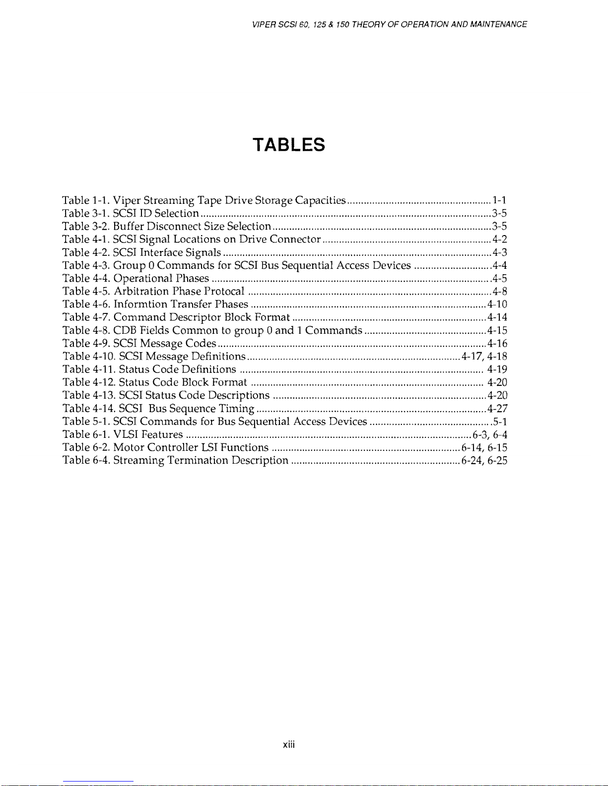
TABLES
Table 1-1. Viper Streaming Tape Drive Storage Capacities ....................................................
1-1
Table 3-1. SCSI ID Selection ......................................................................................................... 3-5
Table 3-2. Buffer Disconnect Size Selection ...............................................................................
3-5
Table
4-1.
SCSI Signal Locations on Drive Connector ............................................................. 4-2
Table
4-2.
SCSI Interface Signals .................................................................................................
4-3
Table
4-3.
Group 0 Commands
for SCSI Bus Sequential Access Devices ............................
4-4
Table
4-4.
Operational Phases .....................................................................................................
4-5
Table
4-5.
Arbitration Phase Protocal ........................................................................................ 4-8
Table 4-6. Informtion Transfer Phases .....................................................................................
4-10
Table
4-7.
Command
Descriptor Block Format ..................................................................... .4-14
Table
4-8.
CDB Fields Common to
group 0 and 1 Commands
........................................... .4-15
Table
4-9.
SCSI Message Codes ................................................................................................. 4-16
Table
4-10. SCSI Message Definitions ............................................................................ .4-17, 4-18
Table 4-11. Status
Code
Definitions ........................................................................................ 4-19
Table 4-12. Status Code Block Format ....................................................................................
4-20
Table 4-13. SCSI Status
Code
Descriptions ............................................................................. 4-20
Table 4-14. SCSI Bus Sequence Timing ................................................................................... 4-27
Table
5-1.
SCSI
Commands
for Bus Sequential Access Devices ...........................................
.5-1
Table
6-1.
VLSI Features .......................................................................................................
6-3,
6-4
Table
6-2.
Motor
Controller
LSI
Functions .................................................................... 6-14,
6-15
Table
6-4.
Streaming Termination Description ............................................................. 6-24,
6-25
xiii
Page 14
VIPER SCSI
60,
125 & 150 THEORY
OF
OPERATION
AND
MAINTENANCE
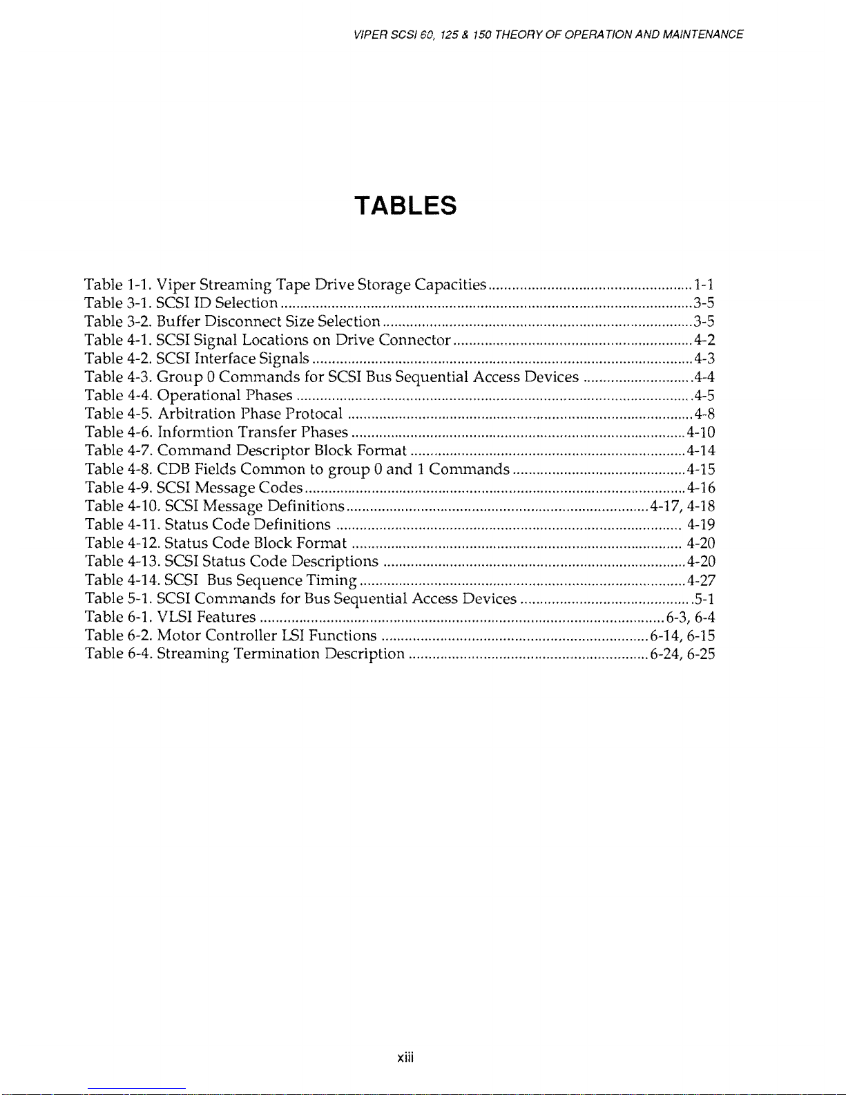
TABLES
Table
1-1.
Viper Streaming Tape Drive Storage Capacities ....................................................
1-1
Table
3-1.
SCSI ID Selection .........................................................................................................
3-5
Table
3-2.
Buffer Disconnect Size Selection ...............................................................................
3-5
Table
4-1.
SCSI Signal Locations on Drive Connector ............................................................. 4-2
Table
4-2.
SCSI Interface Signals .................................................................................................
4-3
Table
4-3.
Group a Commands
for SCSI Bus Sequential Access Devices ............................
4-4
Table
4-4.
Operational Phases .....................................................................................................
4-5
Table
4-5.
Arbitration Phase Protocal ........................................................................................
4-8
Ta ble 4-6. Informtion Transfer Phases .....................................................................................
4-10
Table 4-7.
Command
Descriptor Block Format ......................................................................
4-14
Table
4-8.
CDB Fields
Common
to
group a and 1 Commands
........................................... .4-15
Table
4-9.
SCSI Message Codes .................................................................................................
4-16
Table 4-10. SCSI Message Definitions ............................................................................ .4-17,
4-18
Table
4-11.
Status
Code
Definitions ........................................................................................
4-19
Table
4-12.
Status
Code
Block Format ....................................................................................
4-20
Table 4-13. SCSI Status
Code
Descriptions .............................................................................
4-20
Table 4-14. SCSI Bus Sequence Timing ...................................................................................
4-27
Table 5-1. SCSI
Commands
for Bus Sequential Access Devices .......................................... .
Table
6-1.
VLSI Features .......................................................................................................
6-3,
6-4
Table
6-2.
Motor Controller
LSI
Functions .................................................................... 6-14,
6-15
Table 6-4. Streaming Termination Description ............................................................. 6-24,
6-25
xiii
Page 15
1.1
Overview
CHAPTER 1
INTRODUCTION
INTRODUCTION
Archive's
Vipe~
SCSI models
60S,
125S,
and
150S
are
1/4-inch
streaming tape drives that
provide
reliable
and
cost-efficient backup for high-capacity Winchester
disk
drives. Other
applications include software distribution, transaction logging,
data
collection, data
ex-
change,
and
program
loading. Viper SCSI drives, featuring
LSI
circuitry
and
surface-mount
technology, conform
to
ANSI
X3.131
and
QIC format standards. Backward
read
compatibility
with
previous Archive drives is
standard
with
all Viper models.
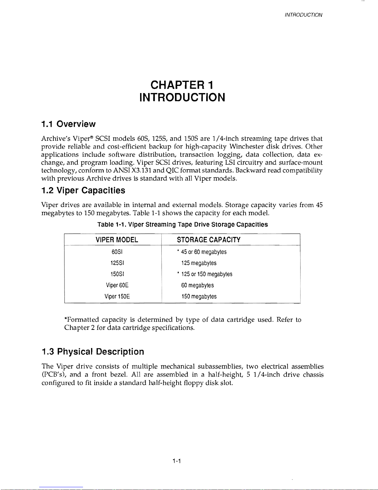
1.2 Viper Capacities
Viper drives are available in internal
and
external models. Storage capacity varies from
45
megabytes to 150 megabytes. Table
1-1
shows
the capacity for each model.
Table 1-1. Viper Streaming
Tape
Drive Storage CapaCities
VIPER
MODEL
STORAGE
CAPACITY
60S1
*
45
or
60
megabytes
125S1
125
megabytes
150S1
*
125
or
150
megabytes
Viper60E
60
megabytes
Viper
150E
150
megabytes
I
*Formatted capacity
is
determined by type of
data
cartridge used. Refer
to
Chapter
2 for
data
cartridge specifications.
1.3 Physical Description
The
Viper
drive
consists
of
multiple mechanical subassemblies, two electrical assemblies
(PCB's),
and
a front bezel. All
are
assembled in a half-height, 5
1/4-inch
drive
chassis
configured
to
fit inside a
standard
half-height floppy
disk
slot.
1-1
Page 16
VIPER
SCSI
60,
125 & 150
THEORY
OF
OPERATION
AND
MAINTENANCE
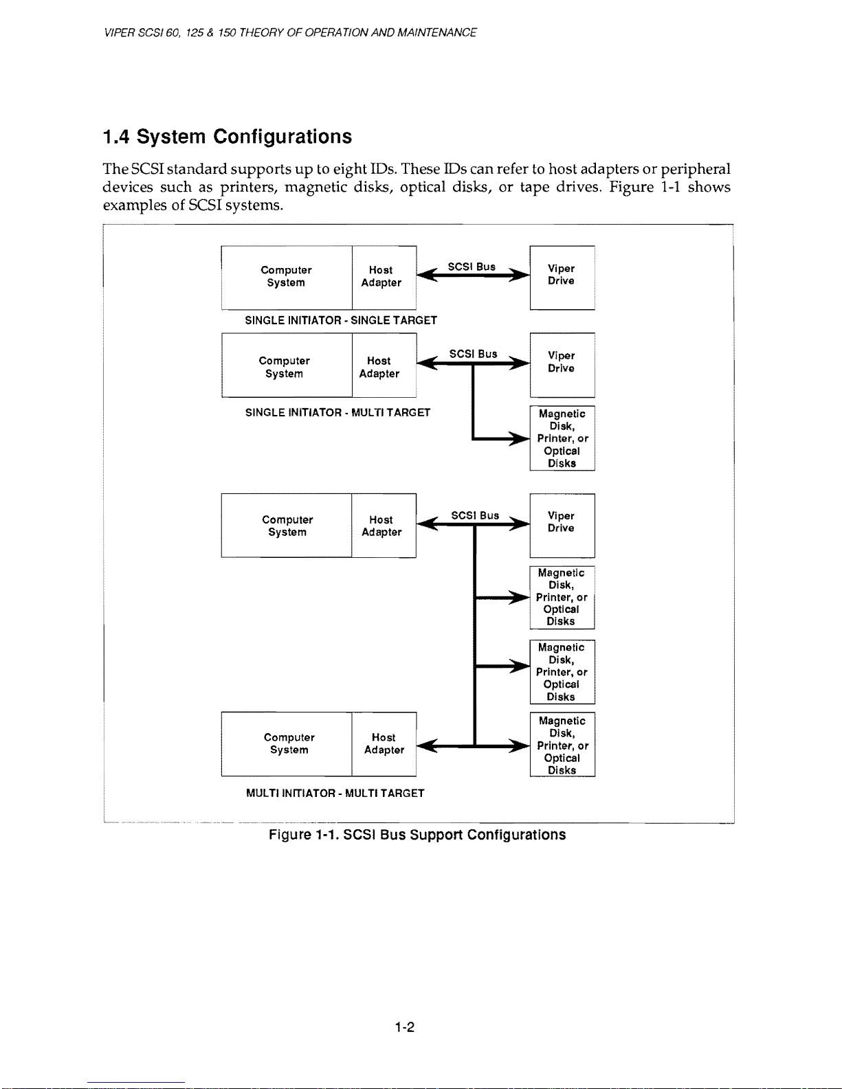
1.4 System Configurations
The SCSI
standard
supports
up
to eight IDs. These IDs can refer
to
host adapters
or
peripheral
devices
such
as printers, magnetic disks, optical disks,
or
tape drives. Figure
1-1
shows
examples of
SCSI systems.
•
-
SCSI
Bus
-
Viper
Computer Host
System
Adapter
.......
,.
Drive
•
SINGLE INITIATOR· SINGLE TARGET
Computer Host
1-
SCSI
Bus
.....
Viper
System
Adapter
......
,..
Drive
•
SINGLE INITIATOR - MULTI TARGET
Magnetic
....
Disk,
,.
Printer,
or
Optical
Disks
Computer Host
.,
SCSI
Bus"
Viper
System Adapter
-.
...
Drive
Magnetic
-
Disk,
,.
Printer,
or
Optical
Disks
Magnetic
.....
Disk •
,.
Printer,
or
Optical
Disks
1-
Magnetic
Computer Host
-
Disk,
System Adapter
......
,..
Printer,
or
Optical
Disks
MULTI INITIATOR - MULTI TARGET
Figure 1-1.
SCSI
Bus Support Configurations
1-2
Page 17
INTRODUCTION
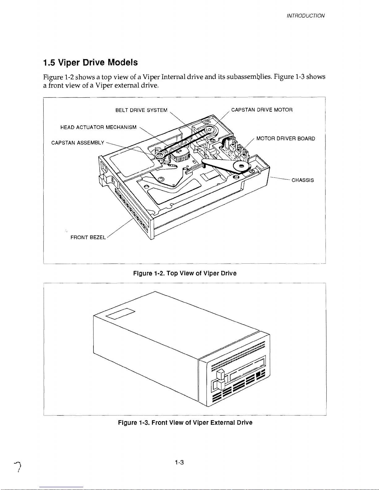
1.5 Viper Drive Models
Figure 1-2 shows a
top
view of a Viper Internal drive and its subassemblies. Figure
1-3
shows
a front view of a Viper external drive.
BELT DRIVE SYSTEM
CAPSTAN DRIVE MOTOR
HEAD ACTUATOR MECHANISM
MOTOR DRIVER BOARD
CAPSTAN ASSEMBLY
--CHASSIS
BEZEL
Figure 1·2. Top View of Viper Drive
Figure 1-3. Front
View of Viper External Drive
1-3
Page 18
VIPER
SCSI
60,
125 &
150
THEORY
OF
OPERATION
AND
MAIfv1ENANCE
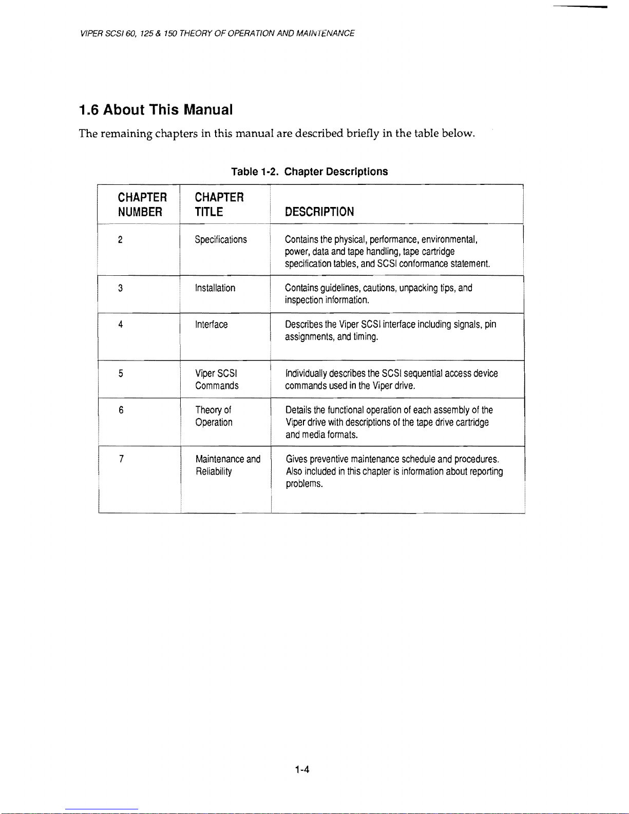
1.6 About This Manual
The remaining chapters in this
manual
are described briefly in
the
table below.
Table
1-2.
Chapter
Descriptions
CHAPTER CHAPTER
NUMBER
TITLE
DESCRIPTION
2
Specifications
Contains
the
physical,
performance,
environmental,
power,
data
and
tape
handling,
tape
cartridge
I
specification
tables,
and
SCSI
conformance
statement.
I
3
Installation
I
Contains
guidelines,
cautions,
unpacking
tips,
and
I
inspection
information.
4
I
Interface
I
Describes
the
Viper
SCSI
interface
including
signals,
pin
assignments,
and
timing.
5
Viper
SCSI
I
Individually
describes
the
SCSI
sequential
access
device
Commands
commands
used
in
the
Viper
drive.
6
Theory
of
Details
the
functional
operation
of
each
assembly
of
the
Operation
Viper
drive
with
descriptions
of
the
tape
drive
cartridge
and
media
formats.
I
7
Maintenance
and
Gives
preventive
maintenance
schedule
and
procedures.
Reliability
Also
included
in
this
chapter
is
information
about
reporting
I
IJfUUltllIll:!.
I
1-4
Page 19
2.1
Overview
CHAPTER 2
SPECIFICATIONS
SPECIFICA TlONS
Archive Viper SCSI drives provide reliable
backup
for microcomputer data. This chapter
includes technical specifications for all Viper models. Information included describes the
following specifications
and
requirements.
• Physical Specifications
•
Power
Requirements
• Drive Performance Specifications
• Environmental Requirements
• Data Cartridge Specifications
• Regulatory Compliance
• SCSI Conformance Statement
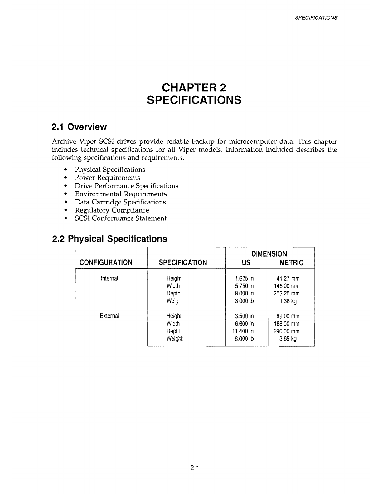
2.2 Physical Specifications
DIMENSION
CONFIGURATION
SPECIFICATION
US
METRIC
Internal
Height
1.625
in
41.27
mm
Width
5.750
in
146.00
mm
Depth
8.000
in
203.20
mm
Weight
3.0001b
1.36
kg
External
Height
3.500
in
89.00
mm
Width
6.600
in
168.00
mm
Depth
11.400
in
290.00
mm
Weight
8.0001b
3.65
kg
2-1
Page 20
VIPER SCSI 60, 125 & 150 THEORY
OF
OPERATION
AND
MAINTENANCE
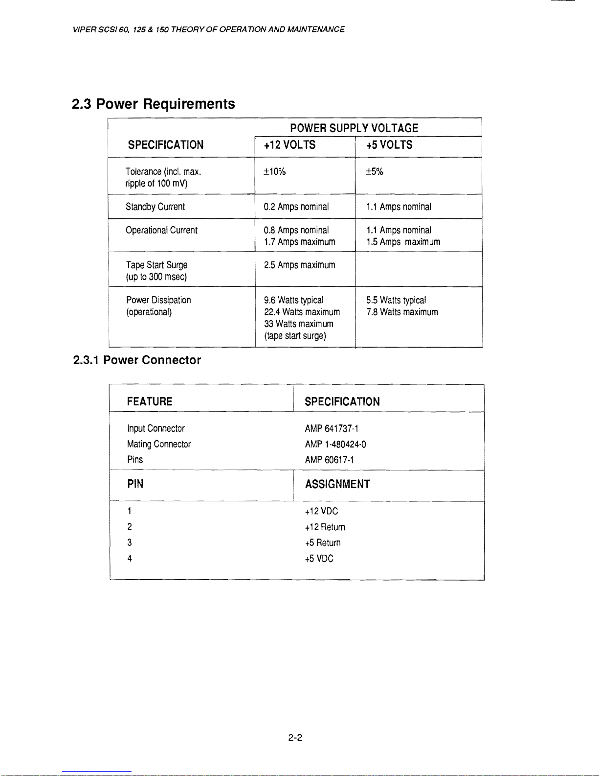
2.3 Power Requirements
I
POWER
SUPPL Y VOLTAGE
SPECIFICATION
+12
VOLTS
+5
VOLTS
I
Tolerance
(inc!.
max.
±10%
±5%
I
ripple
of
100
mV)
Standby
Current
0.2
Amps
nominal
1.1
Amps
nominal
Operational
Current
0.8
Amps
nominal
1.1
Amps
nominal
I
1.7
Amps
maximum
1.5
Amps
maximum
I
Tape
Start
Surge
2.5
Amps
maximum
i
(up
to
300
msec)
Power
Dissipation
9.6
Watts
typical
5.5
Watts
typical
(operational)
22.4
Watts
maximum
7.8
Watts
maximum
i
33
Watts
maximum
i
(tape
start
surge)
2.3.1 Power Connector
FEATURE
SPECIFICATION
Input
Connector
AMP
641737-1
Mating
Connector
AMP
1-480424-0
Pins
AMP
60617-1
PIN
I
ASSIGNMENT
i
1
+12
VDC
2
+12
Retum
3
+5
Retum
4
+5
VDC
2-2
Page 21
SPECIFICATIONS
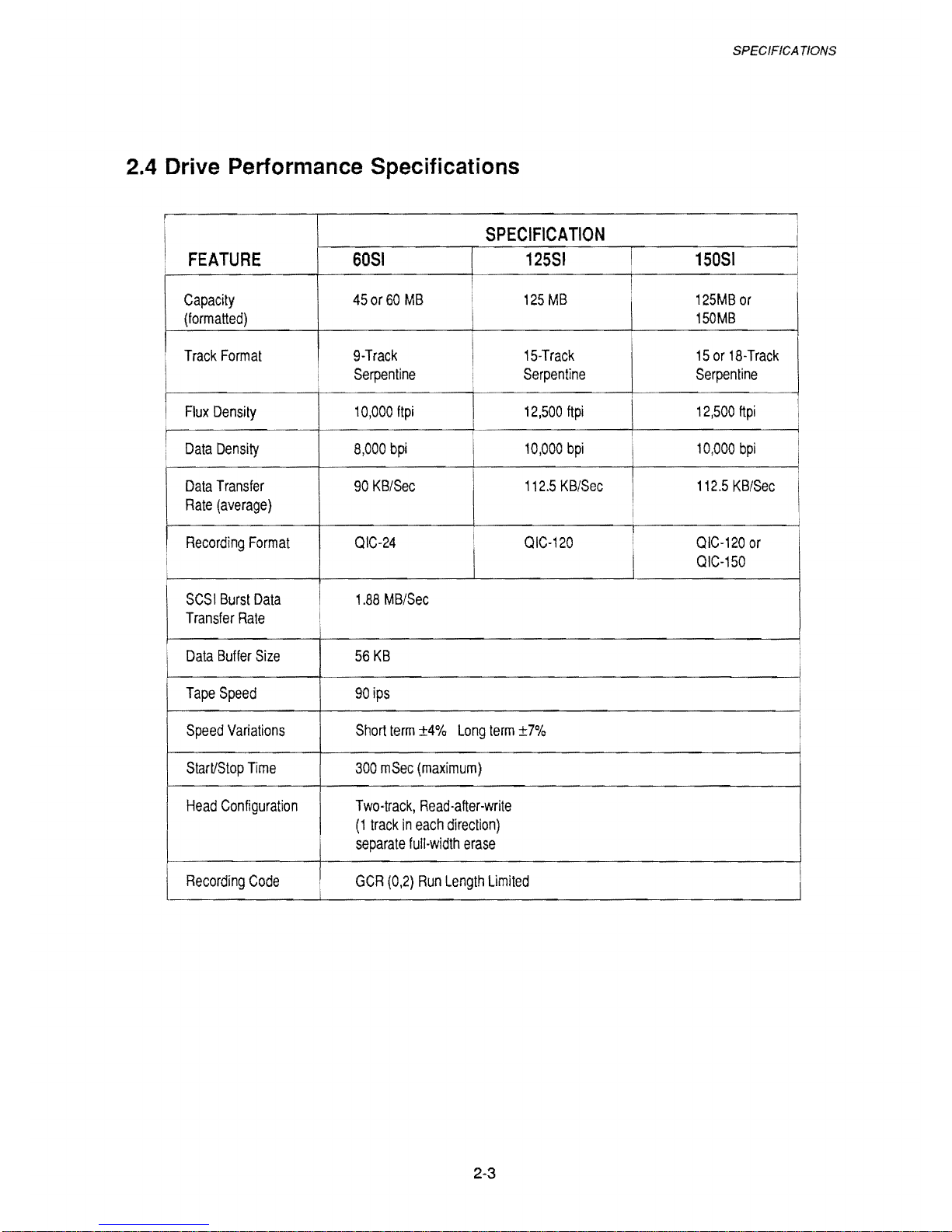
2.4 Drive Performance Specifications
I
SPECIFICATION
i
FEATURE
6051
12551
I
15051
i
i
I
I
Capacity
450r60
MB
i
125
MB
I
125MB
or
(formatted)
I
150MB
I
Track
Format
9-Track
I
15-Track
15
or
18-Track
Serpentine
Serpentine
Serpentine
I
Flux
Density
10,000
ftpi
12,500
ftpi
I
12,500
ftpi
!
I
!
I
Data
Density
8,000
bpi
10,000
bpi
10,000
bpi
I
i
I
Data
Transfer
90
KB/Sec
112.5
KB/Sec
112.5
KB/Sec
I
Rate
(average)
i
Recording
Format
QIC-24
I
QIC-120
!
QIC-120
or
i
I I
QIC-150
SCS I Burst
Data
1.88
MB/Sec
Transfer
Rate
I
Data
Buffer
Size
56
KB
Tape
Speed
90
ips
Speed
Variations
Short
term
±4%
Long
term
±7'%
Start/Stop
Time
300
mSec
(maximum)
Head
Configuration
Two-track,
Read-after-write
(1
track
in
each
direction)
I
separate
full-width
erase
l
Recording
Code
I
..
GCR
(0,2)
Run
Length
limited
2-3
Page 22
VIPER SCSI
60,
125 & 150 THEORY
OF
OPERA TION
AND
MAINTENANCE
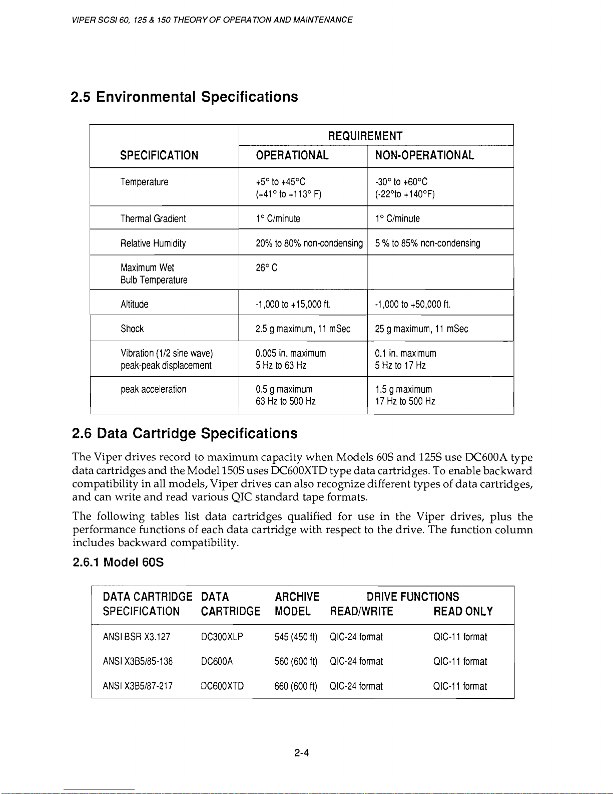
2.5 Environmental Specifications
REQUIREMENT
SPECIFICATION
OPERATIONAL
NON-OPERATIONAL
Temperature
+5°
to
+45°C
-30°
to
+60°C
(
+41 ° to + 113 ° F)
(-22°to + 140°F)
Thermal
Gradient
1°
C/minute
1°
C/minute
Relative
Humidity
20%
to
80%
non-condensing
5 %
to
85%
non-condensing
Maximum
Wet
26°
C
Bulb
Temperature
Altitude
-1,000
to + 15,000
ft.
-1,000
to
+50,000
ft.
Shock
2.5 9 maximum,
11
mSec
25 9 maximum,
11
mSec
Vibration
(1/2
sine
wave)
0.005
in.
maximum
0.1
in.
maximum
peak-peak
displacement
5
Hz
to
63
Hz
5
Hz
to
17
Hz
peak
acceleration
0.5 9 maximum
1.5 9 maximum
63
Hz
to
500
Hz
17Hzt0500Hz
2.6 Data Cartridge Specifications
The Viper drives record to
maximum
capacity
when
Models
60S
and
1255
use
DC600A type
data
cartridges
and
the Model 1505 uses DC600XTD type
data
cartridges. To enable
backward
compatibility in all models, Viper drives can also recognize different types of
data
cartridges,
and
can write
and
read
various QIC
standard
tape
formats.
The following tables list
data
cartridges qualified for
use
in the Viper drives,
plus
the
performance functions of each
data
cartridge
with
respect to the drive. The function
column
includes
backward
compatibility.
2.6.1 Model 60S
I
DATA
CARTRIDGE
DATA
ARCHIVE
DRIVE
FUNCTIONS
SPECIFICATION
CARTRIDGE
MODEL
READ/WRITE
READ
ONLY
ANSI
BSR
X3.127
DC300XLP
545
(450
It)
OIC-24
format
OIC-11
format
ANSI
X3B5/85-138
DC600A
560
(600
It)
OIC-24
format
OIC-11
format
ANSI
X385/87-217
DC600XTD
660
(600
It)
OIC-24
format
OIC-11
format
2-4
Page 23
SPEC/FICA
nONS
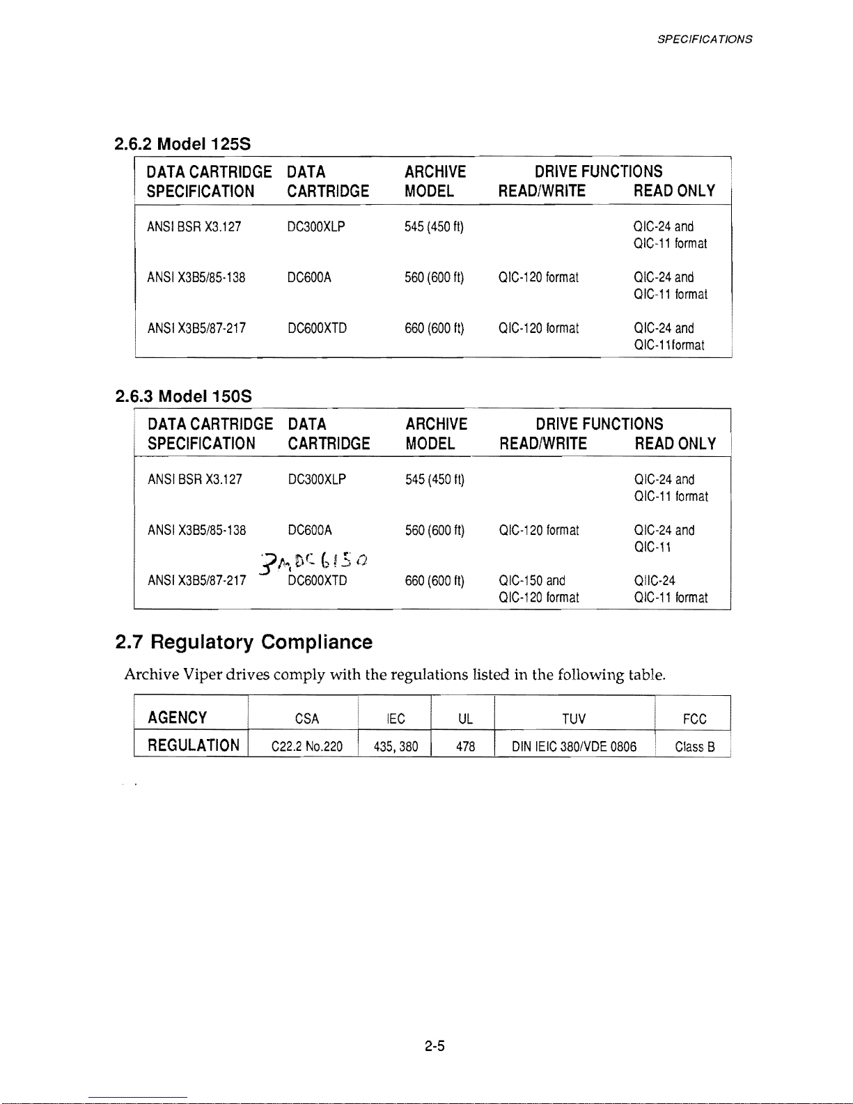
2.6.2 Model 125S
I
DATA
CARTRIDGE
DATA
ARCHIVE
DRIVE
FUNCTIONS
.
SPECIFICATION
CARTRIDGE
MODEL
READ/WRITE
READ
ONLY
ANSI
BSR
X3.127
DC300XLP
545
(450
It)
QIC-24
and
QIC-11
format
ANSI
X3B5/85-138
DC600A
560
(600
It)
Q
IC-120
format
QIC-24
and
QIC-11
format
ANSI
X3B5/87-217
DC600XTD
660
(600
It)
QIC-120
format
QIC-24
and
QIC-111ormat
2.6.3 Model 150S
DATA
CARTRIDGE
DATA
ARCHIVE
DRIVE
FUNCTIONS
SPECIFICATION
CARTRIDGE
MODEL
READ/WRITE
READ
ONLY
I
ANSI
BSR
X3.127
DC300XLP
545
(450
It)
QIC-24
and
QIC-11
format
ANSI
X3B5/85-138
DC600A
560
(600
It)
QIC-120
format
QIC-24
and
".1
''''I
OC
()
l.5
Q
QIC-11
ANSI
X3B5/87-217
QIC-150
and
QIIC-24
DC600XTD
660
(600
It)
QIC-120
format
QIC-11
format
2.7 Regulatory Compliance
Archive Viper drives comply with the regulations listed in the following table.
AGENCY
CSA
I
IEC
UL
TUV
FCC
I
REGULATION
I
C22.2
No.220 I 435,380
478
DIN
IEIC
380IVDE
0806
Class
B
2-5
Page 24
VIPER SCSI 60, 125 & 150 THEORY
OF
OPERA TlON
AND
MAINTENANCE
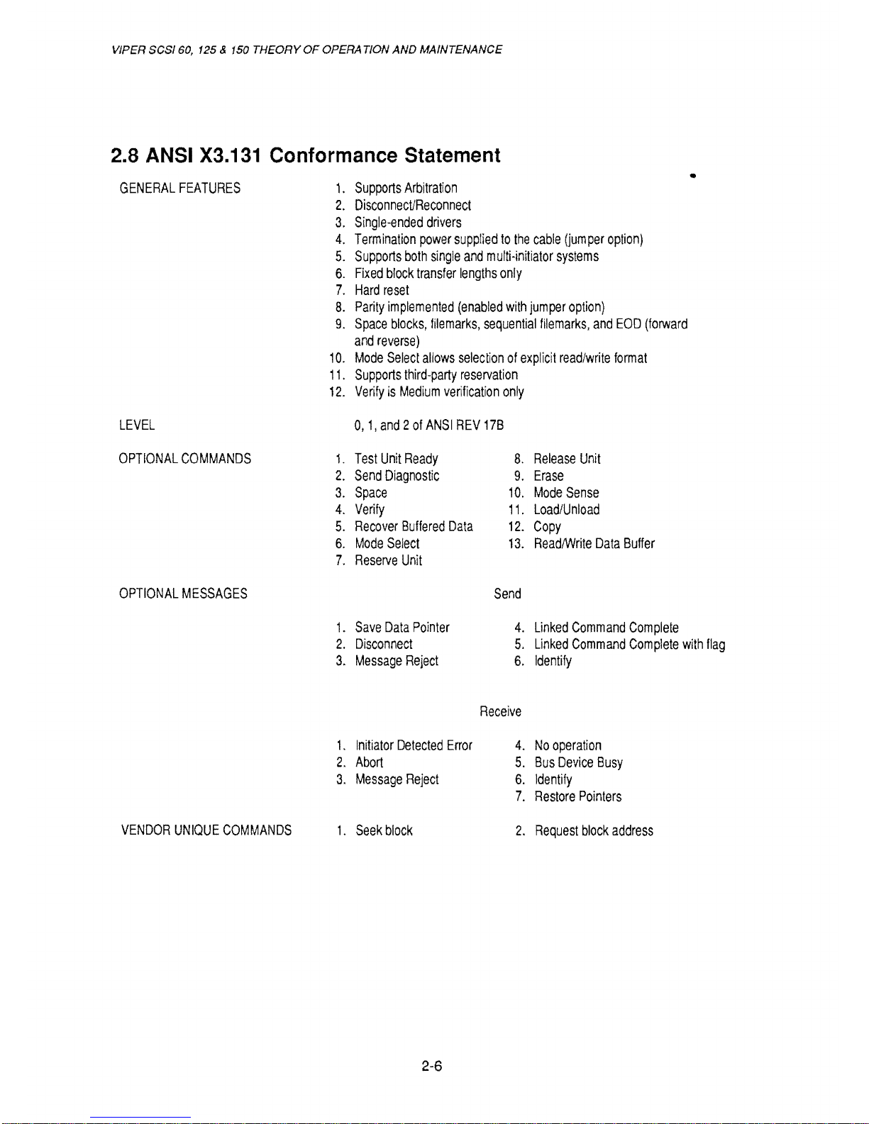
2.8 ANSI X3.131 Conformance Statement
•
GENERAL
FEATURES
1.
Supports
Arbitration
2.
Disconnect/Reconnect
3.
Single-ended
drivers
4.
Termination
power
supplied
to
the
cable
(jumper
option)
5.
Supports
both
single
and
mUlti-initiator
systems
6.
Fixed
block
transfer
lengths
only
7.
Hard
reset
B.
Parity
implemented
(enabled
with
jumper
option)
9.
Space
blocks,
filemarks,
sequential
filemarks,
and
EOD
(forward
and
reverse)
10.
Mode
Select
allows
selection
of
explicit
read/write
format
11.
Supports
third-party
reservation
12.
Verify
is
Medium
verification
only
LEVEL
0,1,
and 2 of
ANSI
REV
178
OPTIONAL
COMMANDS
1-
Test
Unit
Ready
B.
Release
Unit
2.
Send
Diagnostic
9.
Erase
3.
Space
10.
Mode
Sense
4.
Verify
11.
Load/Unload
5.
Recover
Buffered
Data
12.
Copy
6.
Mode
Select
13.
ReadlWrite
Data
Buffer
7.
Reserve
Unit
OPTIONAL
MESSAGES
Send
1.
Save
Data
Pointer
4.
Linked
Command
Complete
2.
Disconnect
5.
Linked
Command
Complete
with
flag
3.
Message
Reject
6.
Identify
Receive
1.
Initiator
Detected
Error
4.
No
operation
2.
Abort
5.
Bus
Device
Busy
3.
Message
Reject
6.
Identify
7.
Restore
Pointers
VENDOR
UNIQUE
COMMANDS
1.
Seek
block
2.
Request
block
address
2-6
Page 25
3.1
Introduction
CHAPTER 3
INSTALLATION
INSTALLA
TlON
This chapter briefly describes installation procedures for internal
and
external Viper tape
drives
but
does not contain detailed instructions.
The Archive external Viper requires
an
adapter card. The
SC402
adapter
for
PC/
AT
compat-
ible computers
and
the
SC409
adapter for
PS/2
and
compatible computers are available from
Archive Corporation.
3.2 Guidelines and Cautions
The following guidelines
and
cautions are industry standards
and
apply to handling and
installing all Archive products.
• Archive drives contain components that are sensitive to static electricity. They are
shipped in protective anti-static bags. Do not remove the drive from the anti-static bag
until you are ready to install
it.
• Before removing a circuit board
or
drive from the protective packaging, discharge
static electricity from
your
body
by touching the computers metal surface or any
known
grounded
surface.
• Hold the drive by its edges only; touching the printed circuit board can cause
component damage. Lay the drive only on top of the bag or return
it
to the bag.
• Clean the head at the recommended intervals. Failure to
do
this can cause excessive
data
errors.
• Maintain input power within specification limits to insure reliable operation.
3.3 Unpacking and Inspection
Archive products are inspected
and
carefully packaged at the factory; however, damage can
occur
during
shipping. Follow these steps for inspecting
and
unpacking.
1. Visually inspect shipping containers; notify
your
carrier immediately of any damage.
2.
Place shipping containers on a flat, clean, stable surface; carefully remove
and
verify
contents.
If
parts are missing
or
equipment
is
damaged, notify
your
Archive represen-
tative.
3.
Save containers
and
packing materials for any future reshipment.
3-1
Page 26
VIPER
SCSI
60,
125 & 150 THEORY
OF
OPERA
nON
AND
MAINTENANCE
3.4 Installation
Viper drives can be
mounted
inside a microcomputer
and
connected through the interface
and
power
cables
or
installed externally
and
connected through the interface cable
and
power
cable. The following sections briefly described important installation procedures,
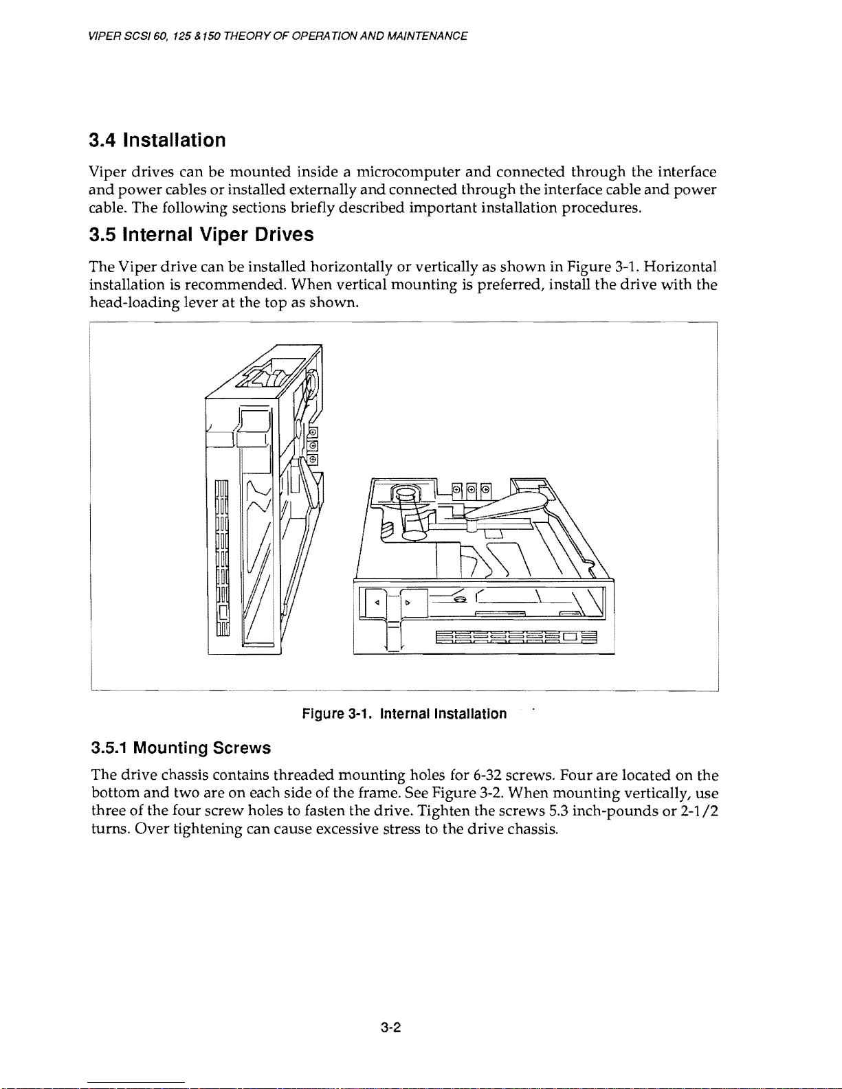
3.5 Internal Viper Drives
The Viper drive can
be
installed horizontally
or
vertically as
shown
in Figure
3-1.
Horizontal
installation
is recommended.
When
vertical mounting is preferred, install the drive
with
the
head-loading lever
at
the top as shown.
Figure 3-1. Internal Installation
3.5.1 Mounting Screws
The drive chassis contains threaded
mounting
holes for 6-32 screws.
Four
are
located
on
the
bottom
and
two are
on
each side
of
the frame. See Figure
3-2.
When
mounting
vertically, use
three
of
the four screw holes to fasten the drive. Tighten the screws 5.3 inch-pounds
or
2-1/2
turns.
Over
tightening can cause excessive stress to the
drive
chassis.
3-2
Page 27
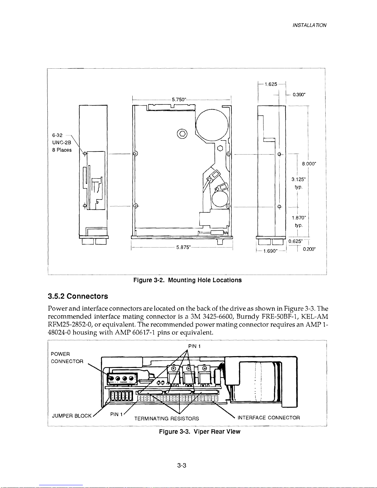
6-32
UNG-2B
8 Places
3.5.2 Connectors
©
1---------------
5
.875"---~----1
Figure 3·2. Mounting Hole Locations
1.625
INSTALLA
TlON
8.000"
3.125"
typo
Power
and
interface connectors are located on the back of the drive as
shown
in Figure
3-3.
The
recommended interface mating connector is a 3M
3425-6600, Burndy FRE-50BF-1, KEL-AM
RFM2S-2852-0,
or
equivalent. The recommended
power
mating connector requires an AMP
1-
48024-0 housing with AMP
60617-1
pins
or
equivalent.
PIN 1
INTERFACE CONNECTOR
Figure 3·3. Viper Rear View
3-3
Page 28
VIPER
SCSI
60,
125 &
150
THEORY
OF
OPERATION
AND
MAINTENANCE
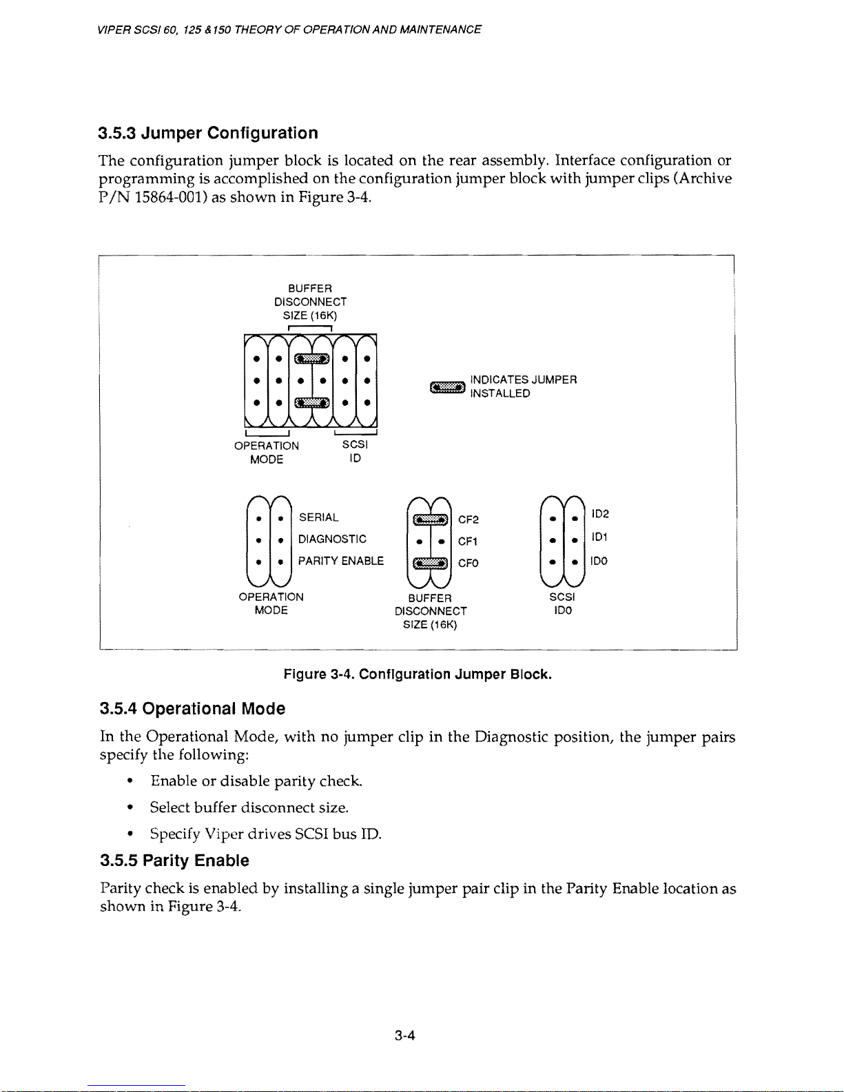
3.5.3 Jumper Configuration
The configuration jumper block is located on the rear assembly. Interface configuration or
programming
is accomplished on
the
configuration jumper block with jumper clips (Archive
PIN
15864-001) as
shown
in Figure 3-4.
BUFFER
DISCONNECT
SIZE
(16K)
i i
• •
• •
• •
•
•
• •
OPERATION
MODE
L...--.-....I
SCSI
10
• •
SERIAL
• •
DIAGNOSTIC
•
•
PARITY ENABLE
OPERATION
MODE
~
INDICATES JUMPER
~
INSTALLED
CF2
•
•
CF1
•
•
CFO
•
•
BUFFER
SCSI
DISCONNECT
100
SIZE
(16K)
Figure
3-4.
Configuration
Jumper
Block.
3.5.4 Operational Mode
102
101
100
In the Operational Mode, with no jumper clip in the Diagnostic position, the jumper pairs
specify the following:
• Enable or disable parity
check
• Select buffer disconnect size.
• Specify Viper drives SCSI bus
ID.
3.5.5 Parity Enable
Parity check is enabled by installing a single jumper pair clip in the Parity Enable location
as
shown in Figure 3-4.
3-4
Page 29
INSTALLATION
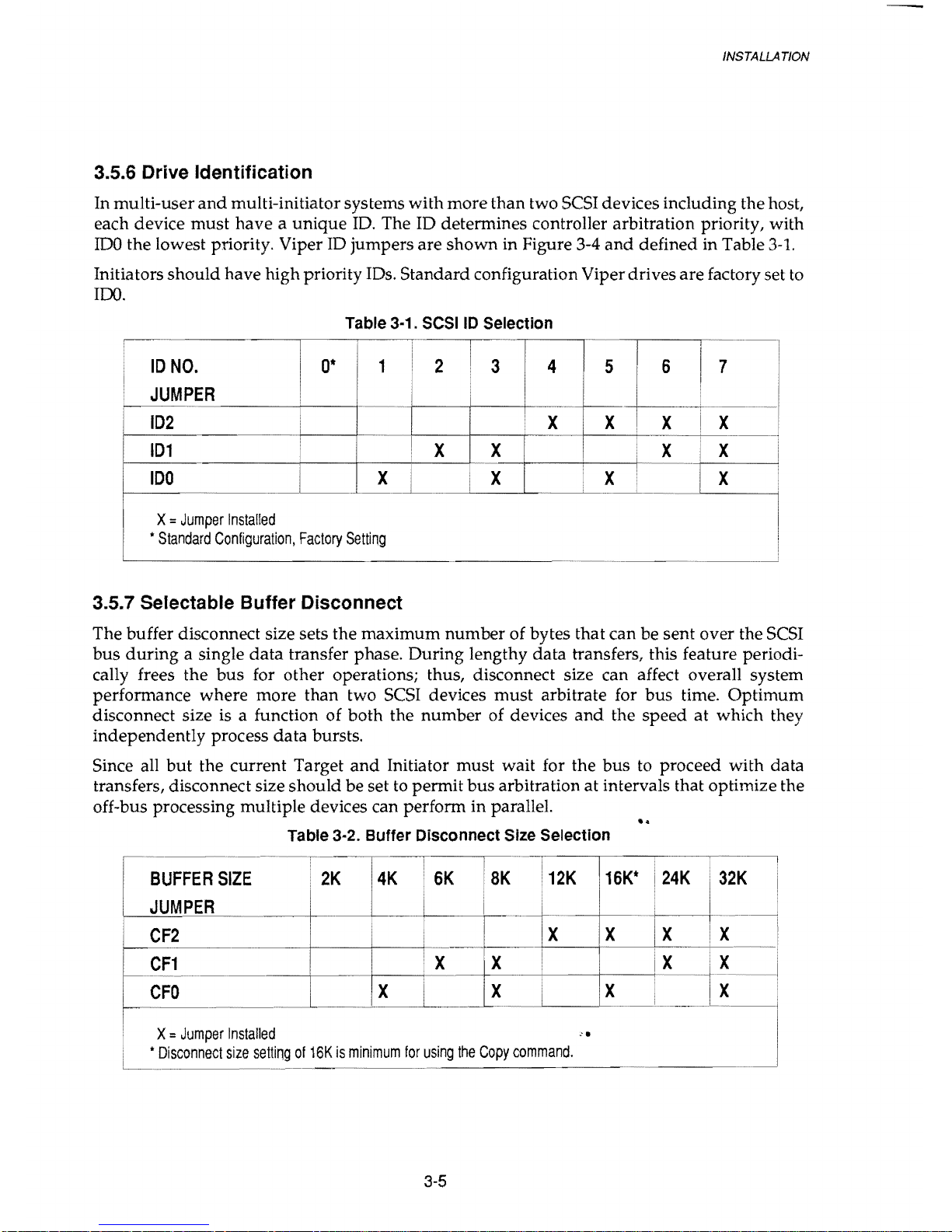
3.5.6 Drive Identification
In multi-user
and
multi-initiator systems with more than two SCSI devices including the host,
each device
must
have a unique
ID.
The ID determines controller arbitration priority, with
IDO
the lowest priority. Viper ID jumpers are shown in Figure 3-4
and
defined in Table
3-1.
Initiators
should
have high priority IDs. Standard configuration Viper drives are factory set
to
100.
Table 3-1. SCSI ID Selection
,~-
.....
I
I
.....
I
....
10
NO.
0*
1
2 3 4
JUMPER
I
102
I
I
X
X
X X
101
!
!
X X
X
i
X
100
I
X
I
I
X X
X =
Jumper
Installed
•
Standard
Configuration,
Factory
Setting
3.5.7 Selectable Buffer Disconnect
The buffer disconnect size sets the maximum number of bytes that can be sent over the SCSI
bus
during
a single
data
transfer phase. During lengthy
data
transfers, this feature periodi-
cally frees the
bus
for other operations; thus, disconnect size can affect overall system
performance where more than two SCSI devices
must
arbitrate for bus time.
Optimum
disconnect size is a function of both the number of devices
and
the speed
at
which they
independently process data bursts.
Since all
but
the current Target
and
Initiator must wait for the
bus
to proceed with data
transfers, disconnect size should be set
to
permit
bus
arbitration
at
intervals that optimize the
off-bus processing multiple devices can perform in parallel.
..
Table 3-2. Buffer Disconnect Size Selection
c:
~-
.~.~~-
....
-f~~-
! I
BUFFER
SIZE
.
2K
4K
6K • 8K
JUMPER
....
I I
....
_. --+_
..
~_+--_
..
+--
__
+
-~------i
~
:.1
~~:}
--
X I X I
~_
~....
-'---_--'--X
..
__
,~~_
..
L-----1
16K*
12K
X
X
, X =
Jumper
Installed
•
Disconnect
size
setting
of
16K
is
minimum
for
using
the
Copy
command.
3-5
Page 30
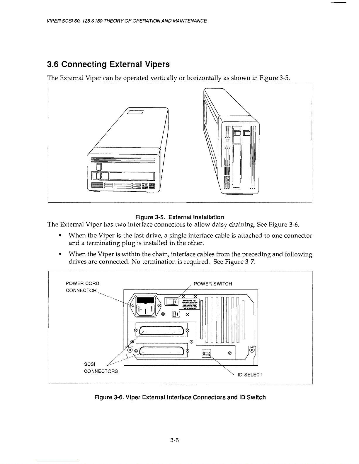
VIPER SCSI 60, 125 & 150 THEORY
OF
OPERATION
AND
MAINTENANCE
3.6 Connecting External Vipers
The External Viper can be operated vertically
or
horizontally as
shown
in Figure 3-5.
Figure 3-5. External Installation
The External Viper has two interface connectors to allow daisy chaining. See Figure 3-6.
• When the Viper
is
the last drive, a single interface cable is attached to
one
connector
and
a tenninating
plug
is
installed in the other.
• When the Viper is within the chain, interface cables from the preceding
and
following
drives are connected. No tennination
is
required. See Figure 3-7.
POWER CORD
CONNECTOR
SCSI
CONNECTORS
POWER SWITCH
ID
SELECT
Figure 3-6. Viper External Interface Connectors and
10
Switch
3-6
Page 31

INS
TA
LLA
TION
3.6.1 SCSI Drive Identification Switch
The ID select
on
the rear of the external Viper incorporates a digital display
with a button
on
each side to change the display
and
set drive identification. See Figure 3-6.
•
Push
the left
button
to decrease the number.
•
Push
the right
button
to increase the number.
•
Other
usual
features such as disconnect size
and
parity
are
selectable only
by
jumpers
on
the PCB.
VIPER AS THE FINAL DEVICE
~~,------------,J
:r--
I
%"
~~'~
I
~I;:::r-------,VIPER
TERMINATOR
VIPER WITHIN A CHAIN
L-
_______
~_~J
Figure 3-7. Viper SCSI Daisy-Chain Diagram
3-7
Page 32

4.1
Overview
CHAPTER 4
INTERFACE
INTERFACE
Viper streaming tape drives are designed to operate with the Small Computer System
Interface
(SCSI)
bus. This chapter discusses
SCSI
bus operation as it pertains
to
Viper
drive functions.
SCSI is a standard interface established to support peripheral eqUipment such as printers,
tape drives, magnetic disks, optical disks for microcomputers
and
other computer sys-
tems. The
SCSI
bus can support
up
to eight IDs consisting of any multiple of host adaptors
and
peripheral devices.
The interface is an eight-port, daisy-chained bus using eighteen signal lines: nine data-bit
signal lines
and
nine control lines. The nine data bit lines consist of eight signal lines
and
one parity-bit line. The remaining nine lines are for control
and
status signals to coordi-
nate data transfer operations between the host controller
and
the selected drive.
The Viper drive has
an
internal
SCSI
controller integrated into the drive electronics. Each
device
ID
on the
SCSI
bus may drive
up
to 8 logical units (LUN). The Viper drive
addresses only LUN
O.
4.1.1 ANSI SCSI Bus Standards
Besides studying the information presented in this manual, we recommend you read
ANSI
X3.131
SCSI
bus standard
and
QIC-l04
(SCSI
sequential storage device implemen-
tation standard) before writing host software drivers.
See Archive's conformance state-
ment in SPECIFICATIONS.
4.1.2
Signal Notation Conventions
All
SCSI bus interface signals are active-low. The following conventions are used
to
describe SCSI interface signal notation.
• A signal name
or
abbreviation preceded by a minus sign
(-)
indicates the signal
is
active low.
Example:
-MSG
4-1
Page 33

VIPER
SCSI
60,
125 &
150
THEORY
OF
OPERATION
AND MAINTENANCE
4.2 SCSI Bus Connector Signals
The SCSI signal locations
on
the PCB connector
and
a description of each signal are
shown
in Table
4-1.
NOTE:
All
odd
pins,
except
Pin
25,
are
connected
to
signal
ground
at
the
host.
Pin
25
is
left
open.
Table 4·1. SCSI Signal Locations on Drive Connector
PIN
SIGNAL
DESCRIPTION
SIGNAL
DRIVER
2
-DB(O)
Data
Bus
Bit 0 (LSB)
TargeUlnitiator
4
-DB(1)
Data
Bus
Bit
1
TargeUlnitiator
6
-DB(2)
Data
Bus
Bit
2
TargeUlnitiator
8
-DB(3)
Data
Bus
Bit
3
TargeUlnitiator
10
-DB(4)
Data
Bus
Bit
4
TargeUlnitiator
12
-DB(5)
Data
Bus
Bit
5
TargeUlnitiator
14
-DB(6)
Data
Bus
Bit6
TargeUlnitiator
16
-DB(7)
Data
Bus
Bit 7 (MSB)
TargeUlnitiator
18
-DB(P)
Data
Bus
Parity
TargeUlnitiator
20
Ground
22
Ground
24
Ground
25
Open
26
Terminator
Power
+5V
(Optional)l
28
Ground
30
Ground
32
-ATN
Attention
Initiator
34
Ground
36
-BSY
Busy
T
argeUlnitiator
38
-ACK
Acknowledge
Initiator
40
-RSP
Reset
Initiator'
42
-MSG
Message
Target
44
-SEL
Select
TargeUlnitiator
46
-C/O
Control/Data
Target
48
-REQ
Request
Target
50
-110
InpuUOutput
Target
1
The
+5V
drive
supply
is
available
on
the
SCSI
connector
as a terminator
power
option.
This
pin
is
connected
to
the
+5V
trhough
a 1
N4001 0 diode
and a 1-Amp
fuse.
The
option
is
factory
installed
and
is
selected
by
an
internal
jumper
on
the
PCB.
2
ANSI
defines
-RST
as a bidirectional
pin.
On
the
Viper
drive,
-RST
is
input
only.
4-2
Page 34

INTERFACE
4.3 Signal Descriptions
The
Viper
drive
SCSI interface consists of eighteen signals.
Nine
are control lines
and
nine
are
data
lines. Data lines include the
parity
signal option. These signals are described in
Table
4-2.
Table 4·2. SCSI Interface Signals
SIGNAL
I
NAME
I
DESCRIPTION
-BSY
Busy
OR-tied
signal
used
to
indicate
the
data
bus
is
in
use.
-SEL
Select
Signal
used
by
an
Initiator
to
select a Target,
or
by a Target
to
re-select
an
Initiator.
SEL
is
driven
by
the
Initiator
during
the
Selection
Phase
and
driven
by
the
Target
during a Reselection-
Phase.
-C/O
Control/Data
Target
driven
signal
used
to
indicate
whether
Control
or
Data
information
is
on
the
data
bus.
True
(low)
indicates
Control,
and
false
(high)
indicates
Data.
-I/O
Input/Output
Target
driven
signal
used
to
control
data
movement
direction
on
the
data
bus
with
respect
to
an
Initiator.
This
signal
is
also
used
to
distinguish
between
the
Selection
and
Reselection
Phases.
True
(low)
indicates
input
to
the
Initiator,
and
false
(high)
indicates
output
from
the
Initiator.
-MSG
Message
Target
driven
signal
used
to
indicate
the
presence
of a Message
Phase
on
the
bus.
True
(low)
indicates
Message
Phase,
and
false
(high)
indicates
Data,
Command,
or
Status
Phase.
-REO
Request
Target
driven
signal
used
to
indicate a request
for a REO/ACK
data
transfer
handshake.
-ACK
Acknowledge
Initiator
driven
signal
used
to
indicate
an
acknowledgement
for
a
REO/ACK
data
transfer
handshake.
-ATN
Attention
Initiator
driven
signal
used
to
indicate
the
Initiator
has
a
message
to
communicate
to
the
Target.
-RST
Reset
OR-tied
signal
used
to
indicate a Reset
condition.
DB(7-0)
Data
Bus
Eight
data-bit
signals
plus a parity-bit
signal
that
form
the
data
bus.
DB
(7)
is
the
MSB
and
has
the
highest
priority
(10
7)
during
.
the
Arbitration
Phase.
DB(P)
Data
Bus
Data
parity
is
odd
and
is a jumper-selectable
option.
Parity
is
not
valid
during
the
Arbitration
Phase.
DB
(P)
is
not
to
be
driven
False
(high)
during
the
Arbitration
Phase.
NOTE:
The
BSY
and
RST
signals
are
the
only
OR-tied
signals.
In
ordinary
bus
operation,
these
signals
may
be
simultaneously
driven
by
two
or
more
drivers.
There
is
no
operational
problem
in
mixing
OR-tied
and
three-state
drivers
on
signals
other
than
BSY
and
RST.
4-3
Page 35

VIPER
SCSI
60.
125 &
150
THEORY
OF
OPERATION
AND
MAINTENANCE
4.4 Command Set Description
Table 4-3 shows the SCSI
X3.131
Group
0 commands for sequential access devices imple-
mented by the Viper drive.
4-4
Page 36

INTERFACE
4.5 SCSI Bus Protocol
Communication
on
the SCSI
bus
occurs between a host
computer
SCSI controller
and
a
peripheral controller. The host controller is the Initiator
and
the peripheral device is the
Target.
Some SCSI
bus
functions are assigned to the Initiator
and
others to
the
Target. The
Initiator arbitrates (enters the Arbitration
Phase of operation) for control
of
the SCSI
bus
and
enters the Selection Phase to select a specific Target such as a Viper drive.
The Target drive can request transfer of command, data, status, information,
or
discon-
nect from the bus. While the Viper drive is disconnected, the
bus
is free to accomplish
other
tasks. While disconnected, the Target drive can process information obtained from
the bus.
If
the Target wants to reconnect,
it
arbitrates for
bus
control. For example, a
Target can res elect
an
Initiator
or
another
Target to continue
an
operation.
The Target
at
times actually becomes an Initiator
and
arbitrates for control of
the
SCSI bus.
For the Viper
drive
this occurs only
during
a Copy operation.
SCSI bus
data
transfer operations
are
asynchronous as defined in
the
ANSI SCSI specifica-
tion
and
follow a defined
request/acknowledge
(REQI ACK)
handshake
protocol.
One
eight-bit
byte
of information can be transferred with each
REQ/
ACK handshake.
The
SCSI
bus
protocol is
divided
into three modes of operation: Waiting Phases, Control
Phases,
and
Information Transfer Phases. These are
subdivided
into the eight operational
phases listed in Table
4-4.
Information on these operational phases is contained in the
following paragraphs.
F
WAITING
PHASES
Table 4-4. Operational Phases
.-
-O-PERA~TI6N~AL~P-H~ASES-~~-·······--~
1
CONTROL
PHASES
INFORMATION
TRANSFER
J
L
1
Bus
free
2.
Arbitration
5.
Command
.
3.
Selection
6.
Data
(Data
In/Data
Out)
_ _
___
4.
Res_e_lec_ti_on_
..
__
~:_~_t:_!~;g_e
(Me=sa_g_e_ln_/M_e_ss~g_e_ou_t)~~
4-5
Page 37

VIPER
SCSI
60,
125 & 150
THEORY
OF
OPERATION
AND MAINTENANCE
4.6 Waiting and Control Phases
The status of the SCSI bus is a function of the control signals. These signals define the
SCSI
as
in
the Waiting Phase (Bus Free Phase), the Control Phases (Arbitration, Selection, or
Reselection),
or
the Information Transfer Phases (Command, Data, Status, or Message).
Viper drives support both a SCSI system with Arbitration Phase
and
a SCSI system
without Arbitration
Phase.
4.6.1 Nonarbitrating Systems
In systems where the Arbitration Phase is not implemented, the allowable sequences are
shown in Figure
4-1.
The normal progression is from the Bus Free Phase to the Selection
Phase
and
from the Selection Phase to one or more of the Information Transfer Phases. See
ANSI
SCSI
X1.31
for detailed discussions of
bus
timing.
BUS FREE
PHASE
RESET CONDITION
~".::
..
:::::~~"""'*'~~~,
COMMAND, DATA,
:,:
SELECTION
PHASE
I
;
I!<';..-_
.....
~
STATUS, OR
~
, MESSAGE
PHASES
Figure
4·1.
Phase
Sequencing
with
Nonarbltration
4.6.2 Arbitrating Systems
In arbitration systems, the sequence of
SCSI
bus phases follows the sequence
shown
in
Figure
4-2.
Operation begins with the Bus Free Phase. Normal progression is from the Bus
Free to the Arbitration
Phase. During Arbitration, Initiators
and
Targets assert for control
of the
SCSI
bus. The bus is awarded to the device with the highest priority
SCSI
bus
address
(DB7).
Arbitration is won by the highest priority
SCSI
device when both
BSY
and
SEL
are
asserted
and
a delay of at least
1200
nSec
(1
bus
clear delay + 1 bus settle delay) occurs
before the Arbitration
Phase ends
and
the Selection Phase begins. Signal timing is shown
in Figure
4-3
and
complete Arbitration Phase protocol is described in Table
4-5.
4-6
Page 38

r-----
RESET CONDITION
J~
)~
t I
1....-
____
...1
Figure 4-2. Phase Sequencing with Arbitration
SIGNALS
(Busy) BSY
(Select) SEL
(Data) DB(7-0,P)
Bus
Free
Phase
I I
;-------1---.
I
r-------'----l
Arbitration ID's
ARBITRATION
PHASE
Initiator
ID
and Target
ID
SELECTION
PHASE
Figure 4-3. Arbitration and Selection Phase Signal Timing
4-7
INTERFACE
Page 39

VIPER
SCSI
60.
125 & 150
THEORY
OF
OPERATION
AND
MAINTENANCE
Table 4·5. Arbitration Phase Protocol
STEP
I
PROCEDURE
I
1.
The
SCSI
device
first
waits
for a Bus
Free
Phase
to
occur.
The
I
Bus
Free
Phase
is
detected
when
both
the
BSY
and
SEL
signals
are
simultaneously
and
continuously
false
for a minimum
of a bus
settle
delay
of
400
nSec.
2.
The
SCSI
device
waits a minimum
of
one
bus
free
delay
of
800
nSec
after
detection
of a Bus
Free
Phase
before
driving
any
signal.
The
Bus
Free
Phase
occurs
after
BSY
and
SEL
are
both
i
false
for a bus
settle
delay
of
400
nSec.
3.
Following
the
800
nSec
Bus
Free
Delay
in
Step
2,
the
SCSI
device
Arbitrates
for
the
SCSI
bus
by
asserting
both
BSY
and
its
own
SCSI
10;
however.
the
SCSI
device
does
not
assert a BSY
and
its
SCSI
10
if
more
than a bus
settledelay
(1.8
j.lSec)
has
passed
since
the
Bus
Free
Phase
was
last
observed.
---.-~
..
_._._.
4.
After
waiting
at
least
an
Arbitration
delay
(2.2
j.lSec)
measured
after
asserting a BSY
signal.
the
SCSI
device
examines
the
data
bus.
If a higher
priority
SCSI
10
bit
is
true
then
the
SCSI
device
loses
the
Arbitration
and
the
SCSI
device
releases
its
signals
and
returns
to
Step
1.
If
no
higher
priority
SCSI
10
bit
is
true
on
the
bus,
then
the
SCSI
drive
wins
the
Arbitration
and
it
asserts
the
SEL
signal.
Any
other
device
that
participated
in
the
I
Arbitration
Phase
and
lost
Arbitration
releases
BSY
and
its
SCSI
I
10
bit
within a bus
clear
delay
after
SEL
becomes
true. A SCSI
!
I
device
that
loses
Arbitration
returns
to
Step
1.
:
5.
The
SCSI
device
that
wins
Arbitration
waits
at
least
one
bus
I
clear
delay
plus a bus
settle
delay
of
1,200
nSec
after
asserting
the
SEL
signal
and
changing
the
condition
of
other
signals.
NOTE:
The
single
SCSI
10
bit
on
the
data
bus
corresponds
to
the
unique
10
code
of
the
SCSI
device.
All
other
SCSI
data
bus
bits
are
released
by
the
SCSI
device.
Parity
is
not
valid
during
the
Arbitration
Phase.
During
the
Arbitration
Phase,
DB(P)
may
be
undriven
or
driven
true,
but
not
false.
I
j
4-8
Page 40

INTERFACE
4.7 Selection and Reselection Phases
The Selection
and
Reselection Phases
provide a method
for establishing a link
between
the
Initiator
and
Target.
When
selected
by
the Initiator (read
or
write data),
the
Target has the
option
of disconnecting from
the
SCSI bus.
When
the Target
needs
to
again
establish the
link to its original Initiator, the Target reselects that Initiator.
When
selection is
made,
there are no restrictions on the sequences
between
information
transfer phases. A
phase
type
may
be
followed
by
the
same
phase
type.
For
example, a
data
phase
followed
by
another
data
phase.
A device that
wins
Arbitration
assumes
the roll of Initiator
by
releasing the
I/O
signal.
The Initiator sets
the
data
bus
to a value that is the OR of its SCSI ID bit
and
the Target's ID
bit. The Initiator waits
at
least two
deskew
delays
(90
nSec) before releasing the
BSY
signal
and
an
additional
bus
settle
delay
(400
nSec) before looking for a response from
the
Target.
A device that loses Arbitration
must
release the Select ID
and
BSY.
Operation
enters the Selection
or
Reselection Phases
when a particular
device wins a
request in Arbitration
and
gains control of the SCSI bus. These
phases
allow the device in
control of
the
bus
to select
another
specific device connected to the SCSI
bus
for
commu-
nication.
As
an
example the Initiator can select a Viper
drive
to begin
an
operation,
or
the Viper
drive
can re-select
an
Initiator to continue
an
operation
previously
disconnected.
For
the
Copy
function, the Viper
drive
can act as
an
Initiator
and
select
another
controller
as
a Target source
or
destination for the
Copy
operation.
The Selection
and
Reselection Phases can
be
terminated for either of the following
reasons:
• A Selection/Reselection time-out occurs. A Target
or
Initiator
did
not
respond
to a
Selection
or
Reselection Phase within a
maximum
abort
time of 200
J15ec.
• A reset signal occurs on the SCSI bus,
and
all sequences are
terminated
and
signals
released
by
all Targets
and
Initiators.
The Initiator can
use
the A
TN
signal to notify the Viper
drive
that
an
ID
message
from the
Initiator is ready. To
ensure
the Target recognizes
the
Attention condition before the
Command
Phase
is entered, the
ATN
signal
must
be
low
before the SEL is
asserted
and
BSY
de-asserted.
4-9
Page 41

VIPER
SCSI
60.
125
&
150
THEORY
OF
OPERATION
AND MAINTENANCE
4.8 Information Transfer Phases
The
Command,
Data, Status,
and
Message Phases are
grouped
together as the Informa-
tion Transfer
Phases (Table 4-6) because they
are
all
used
to
transfer
data
or
control
information on the SCSI bus.
Table
4-6
shows the Control Data (C/O),
Input/Output
(I/O),
and
Message (MSG) signals
used
to
distinguish between the various Information Transfer Phases. The Target drives
these three signals
and
thereby controls all changes from one phase to another.
Table 4-6 Information Transfer Phases
I
··
__
··--··--l
SIGNALS!
·MSG
·C/O
·1/0
PHASES
I
DIRECTION
OF
TRANSFER
1
I
·1/0
1 1
Data
Initiator
to
Target
1
0
Data
to
Initiator
0
1
Command
Initiator
to
Target
1
0 0
Status
Target
to
Initiator
0 0
1
Message
Initiator
to
Target
0
0
0
Message
Target
to
Initiator
0=
True
Information Transfer Phases
use
one or more
REQ/
ACK handshakes to control the
information transfer. Each
REQ/
ACK handshake allows the transfer of one byte of
information. During the information transfer phases,
BSY
remains
true
and
SEL remains
false.
C/O,
I/O,
and
MSG
control signals are valid for a bus settle delay of
400
nSec before
assertion of REQ signal
at
the first handshake
and
remain valid until negation of ACK at
the
end
of the last handshake.
4.8.1
Asynchronous Data Transfer
The Target controls the direction of information transfer with the
I/O
signaL When
I/O
is
asserted (low), information is transferred from the Target to the Initiator. When
I/O
is de-
asserted (high), information is transferred from the Initiator
to
the Target. Figure 4-4
shows the
data
transfer signals for information transfer from Target to Initiator,
and
Figure
4-5
shows
the
data
transfer signals for information transfer from Initiator to Target.
Each direction of information transfer is discussed in detail in the following paragraphs.
4-10
Page 42

INTERFACE
4.8.1.1 Transfer from Target to Initiator
The transfer from Target to Initiator is described in
the
following table
and
illustrated in
Figure 4-4.
ACTION
I/O
signal
is
asserted,
the
Target
drives
the
data
(DB7-0)
and
parity
signals
to
their
desired
values.
~
The
Target
then
asserts
the
REO
signal.
t3
The
Initiator
reads
the
data
and
parity
signals
after
REO
is
signals
its
acceptance
of
the
data
by
asserting
the
ACK.
14
ACK
goes
low
at
the
Target.
and
the
Target
deasserts
REO
ts
REO
signal
is
false.
The
Initiator
deasserts
ACK.
After
the
ACK
signal
is
high,
the
Target
can
continue
the
transfer
by
repeating
these
steps
from
t
l'
ACK
---+----~------~
DEASSERTED
ASSERTED
f----
DEASSERTED
ASSERTED
DATA
=f4r--------+-----1
><f
Figure 4-4. Signals Used
in
Transfer from Target to Initiator
4-11
Page 43

VIPER
SCSI
60,
125 & 150
THEORY
OF
OPERATION
AND MAINTENANCE
4.8.1.2 Transfer from Initiator to Target
Transfer from Initiator to Target is described in the following table
and
illustrated in
Figure 4-5.
TIMING
POINT
ACTION
t1
The
1/0
signal
is
deasserted,
and
the
Target
asserts
REO
10
request
infor-
mation.
12
The
Initiator
drives
the
dala
and
parily
signals
to
their
desired
values.
t3
The
Initiator
asserts
the
ACK
.
14
The T argel
deasserts
REO
signaling
its
acceptance
of
data
and
the
Initiator
releases
the
data
and
parity
signals,
and
deasserts
the
ACK
signal.
ts
The
Initiator
deasserts
ACK.
The
Target
can
then
continue
to
transfer
by
t,
t2
t3
t4
ts
i
~Ea~
I
I
I
DEASSERTED
ASSERTED
ACK
I
I
I
DE
ASSERTED
ASSERTED
l><f
Figure
4-5. Signals
Used
In
Transfer
from
Initiator
to
Target
4-12
Page 44

INTERFACE
4.9 Command Phase
During
Command
Phase, the Target requests command information from the Initiator.
The Target asserts the
C/O
signal
and
deasserts the
I/O
and
MSG
signals thus denoting
the
Command
Phase. The
REQ/
ACK then handshakes the
command
bytes across the
SCSI bus (Figure
4-5).
The command bytes are also called the
Command
Descriptor Block
(COB).
4.10 Data Phase
The Data Phase is subdivided into the Data-In
and
Data-Out Phases.
4.10.1 Data-In Phase
During Data-In phase, the Target requests that
data
be sent to the Initiator from the Target.
The Target asserts the
I/O
signal
and
deasserts the
C/O
and
MSG
signals thus denoting
the Data-In Phase. The
REQ/
ACK handshakes (Figure
4-4)
then transfers the requested
byte count.
4.10.2 Data-Out Phase
During a Data-Out phase, the Target requests that
data
be sent from the Initiator to the
Target. The Target deasserts the
C/O,
I/O,
and
MSG
signals thus denoting the Data-Out
Phase.
The
REQ/
ACK handshakes (Figure
4-5)
then transfers the requested byte count
across the
SCSI bus.
4.11
Status Phase
During a Status Phase, the Target requests that status information be sent to the Initiator
from the Target. The Target asserts the
C/O
and
I/O
signals
and
deasserts the
MSG
signal
thus denoting the
Status Phase. The
REQ/
ACK handshakes the one byte status code
across the
SCSI bus (refer to Figure
4-4).
4.12 Message Phase
The Message Phase consists of either the Message-In or Message-Out Phases. The messages the Viper drive supports are all one byte messages.
4.12.1 Message-In Phase
During Message-In Phase, the Target requests that messages be sent to the Initiator from
the Target. The Target asserts the
C/O,
I/O,
MSG
signals thus denoting the Message-In
Phase. The
REQ/
ACK handshakes the one byte message across the
SCSI
bus.
4-13
Page 45

VIPER SCSI 60, 125 & 150 THEORY
OF
OPERATION
AND
MAINTENANCE
4.12.2 Message-Out Phase
During Message-Out Phase, the Target requests that messages be sent from the Initiator
to
the Target. The Target invokes this phase in response to the Attention (A
TIN)
signal
asserted
by
the Initiator. The Viper drive responds
to
the
ATIN
signal at every phase
change. The Target asserts the
C/D
and
MSG
signals
and
deasserts the
I/O
signal,
denoting the Message-Out Phase. The
REQ/
ACK handshakes the one byte message
across the SCSI bus. The Target uses
REQ/
ACQ handshakes (Figure 4-5) until the ATN
signal becomes false, unless
an
error occurs
and
the message
is
rejected.
4.13 Command Descriptor Block
A request to a peripheral device is performed
by
sending a
Command
Descriptor Block
(CDB) to the Target. For several commands, the request
is
accompanied
by
a list of
parameters sent
during
a Data
Out
Phase. If
an
invalid parameter is contained in the CDB,
Viper
drive
terminates the
command
without altering the medium. A typical
Group
0,
six-
byte,
Command
Descriptor Block is
shown
in Table
4-7.
Note that the CDB contains both reserved bit fields
and
defined bit fields. Defined bit
fields are:
Group
Code,
Command
Code, Logical Unit Number,Vendor Unique, Flag,
and
Link, whereas reserved bit fields are defined
by
zeros such as those
appearing
on the last
line of Table
4-7.
Table
4-8
describes the
CDB
fields common to all
Group
0 commands.
Table 4-7. Command Descriptor Block Format
BITS
7
6
5
4
3
2 1
0
BYTE
0
Group
Code
Command
Code
1
Logical
Unit
Number
Command
Dependent
2
Command
Dependent
3
Command
Dependent
4
Command
Dependent
5
Vendor
Unique
I
0 0
I
0 0
Flag
I
Link
4-14
Page 46

-"""
Table 4-8. COB Fields Common to Group 0 and 1 Commands
COMMAND
DESCRIPTOR
BLOCK
FIELD
Group
Code
1
Command
Code
1
Logical
Unit
Number2
Flag
bit
Link
bit
3
DESCRIPTION
This
field
indicates
which
of
eight
possible
SCSI
command
groups
is
specified.
Viper
drive
supports
Group
O.
This
field
indicates
which
of
32
possible
command
codes
for a particular
group
code
is
specified.
The
LUN
must
be
set to
zero.
When
set,
these
bits
select
vendor
unique
functions
in
specified
commands.
The
Flag
bit
is
used
only
in
conjunction
with
the
Link
bit
and
must
be
set
to
zero
if
the
Link
bit
is
zero.
When
the
Link
bit
is
set,
the
value
of
the
Flag
bit
determines
the
appropriate
message
to
send
to
the
Initiator
when
a
linked
command
completes
successfully;
value
zero
indicates
the
Linked
Command
Complete
message
is
required,
value
one
indicates
the
Linked
Command
Complete
with
Flag
message
is
required.
Typically,
the
Flag
bit
is
used
to
cause
an
interrupt
in
the
Initiator
at
the
end
of
or
at
logical
intervals
in
linked
command
processing.
The
Link
bit
is
used
to
indicate
that
the
Initiator
desires
automatic
linking
to
the
next
command
upon
success-
ful
completion
of
the
current
command.
When
the
Link
bit
is
one,
upon
successful
termination
of
the
com-
mand,
Viper
drive
returns
Intermediate
Status
followed
by
one
of
the
two
Command
Complete
messages
as
determined
by
the
Flag
bit.
(Refer
to
description
of
Flag
bit
above).
1.
Together,
group
code
and
command
code
make
up
the
op
code.
2.
If
a
non-zero
logical
unit
number
is
received
in a COB, a Check
Condition
status
is
returned
and
Extended
Sense
Key
is
set
to
Illegal
Request.
3.
If
the
Link
bit
is
used,
all
applicable
commands
must
have
the
Immed
bit
set
a
Check
Condition
status
is
returned
and
Extended
Sense
Key
is
set
to
Request.
4-15
INTERFACE
Page 47

VIPER
SCSI
60.
125 &
150
THEORY
OF
OPERATION
AND MAINTENANCE
4.14 SCSI Message Descriptions and Definitions
The
SCSI
message codes, descriptions, and directions are given in Table
4-9.
SCSI message
definitions are given in Table
4-10.
Each of these
SCSI
messages are supported by the
Viper drive.
4-16
Page 48

INTERFACE
Table
4·10.
SCSI
Message
Definitions
MESSAGE
[
~~;E
[
DEFINITION
__
-~J
ABORT
BUS
DEVICE
RESET
(06h)
This
message
is
sent
from
an
Initiator
to
clear
present
drive
operation.
All
pending
data
and
status
for
the
issuing
Initiator
is
cleared
and
the
drive
goes
back
to
Bus
Free
Phase.
No
status
or
ending
message
is
sent
for
the
operation.
Any
previously
set
modules
will
not
be
changed.
(OCh)
This
message
is
sent
from
an
Initiator
to
direct
the
drive
to
clear
all
current
commands,
and
forces
the
drive
to
an
initial
state
with
no
operations
pending
for
any
Initiator.
Upon
recognizing
this
message,
the
drive
moves
to
the
Bus
Free
Phase.
All
modes
will
be
reset
to
the
default
state.
COMMAND
COMPLETE
(DOh)
This
message
is
sent
from
the
Viper
drive
to
an
Initiator
to
indicate
that
execution
of a command
has
terminated
and
that
valid
status
has
been
sent
to
the
Initiator.
After
successfully
sending
this
message,
the
drive
goes
to
the
Bus
Free
Phase
by
releasing
BSY.
DISCONNECT
NOTE:
The
command
may
have
been
executed
suc-
cessfully
or
unsuccessfully
as
indicated
in
the
status.
(04h)
This
message
is
sent
from
the
Viper
drive
to
inform
an
Initiator
that
the
present
physical
path
is
going
to
be
broken
(Viper
drive
plans
to
disconnect
by
releasing
BSY),
and
that a later
reconnect
will
be
required
to
complete
the
current
operation.
If
the
Initiator
detects
the
Bus
Free
Phase,
other
than
as
the
result
of
a
Reset
condition,
without
first
receiving a Disconnect
or
Command
Complete
message,
the
Initiator
considers
this
as a catastrophic
error
condition.
The
Disconnect
message
does
not
cause
the
Initiator
to
save
the
data
pOinter.
If
Disconnect
messages
are
used
to
break
a
long
data
transfer
into
two
or
more
shorter
transfers,
then a Save
Data
Pointer
message
is
issued
by
the
Viper
drive
before
each
Disconnect.
NOTE:
Configuration
jumpers
are
used
to
select
the
disconnect
size
(refer
to
Chapter
6,
Theory
of
Opera-
tion).
4-17
Page 49

VIPER SCSI 60, 125 & 150 THEORY
OF
OPERATION
AND
MAINTENANCE
Table 4-10. SCSI Message Definitions Continued
HEX
MESSAGE
CODE
DEFINITION
IDENTIFY
These
messages
are
sent
by
either
the
Initiator
(SOh -S7h
or
Viper
drive
to
establish
the
physical
path
connection
No
Disconnect'Reconnect)
between
them.
The
physical
path
connection
indicates
(COh-C7h
Disconnect'Reconnect)
both
the
Initiator
and
Viper
drive
have
message
passing
capability.
Bit 7 is
set
to
one
to
distinguish
these
messages
from
other
messages.
Bit 6 is
set
to
one
by
the
Initiator
indicating
the
Initiator
has
the
ability
to
accommodate
dis-
connection
and
reconnection.
Bits S through 3 are
reserved
(set
to
zero).
Bits 2 through 0 specify
the
logical
unit
number
that
must
be 0 for
the
Viper
drive.
When
Identify
is
sent
from
the
drive
to
an
Initiator
during
reconnection,
an
implied
Restore
Pointers
message
is
performed
by
the
Initiator
prior
to
completion
of
this
message.
INITIATOR
DETECTED
ERROR
This
message
is
sent
from
an
Initiator
to
inform
Viper
drive
(OSh)
an
error,
such
as a parity
error,
has
occurred.
LINKED
COMMAND
COMPLETE
This
message
is
sent
from
Viper
drive
to
an
Initiator
to
(OAh)
indicate
that
execution
of a linked
command
is
completed
and
that
status
was
sent.
The
Initiator
can
then
set
the
pOinters
to
the
initial
state
for
the
next
linked
command.
LINKED
COMMAND
COMPLETE
This
message
is
sent
from
Viper
drive
to
an
Initiator
WITH
FLAG
(OBh)
to
indicate
that
execution
of a linked
command
with
the
Flag
bit
set
to
one,
is
completed
and
that
status
was
sent.
The
Initiator
then
sets
the
current
pOinters
to
the
initial
state
of
the
next
linked
command.
Typically
this
message
is
used
to
cause
an
interrupt
in
the
Initiator
between
two
linked
commands.
MESSAGE
RE.IECT
(07h)
This
message
is
sent
from
Viper
drive
to
indicate
the
last
message
it
received
was
inappropriate
or
was
not
imple-
mented.
The
Viper
drive
sends
Message
Reject
and
then
goes
to
the
Message-In
phase
prior
to
requesting
additional
message
bytes
from
the
Initiator.
This
provides
an
interlock
so
the
Initiator
can
determine
which
message
was
rejected.
NO
OPERATION
(OSh)
This
message
is
sent
from
an
Initiator
in
response
to
a
Viper
drive
request
for a message,
when
the
Initiator
does
not
currently
have
any
other
valid
message
to
send.
SAVE
DATA
POINTER
(02h)
This
message
is
sent
from
Viper
drive
to
direct
the
Initiator
to
save a copy
of
the
present
active
data
pOinter
for
Viper
drive.
4-18
Page 50

INTERFACE
An Initiator that accommodates disconnect/reconnect can indicate this to the Viper drive
during
the Selection phase by asserting A
TN
before bus condition
SEL
true
and
BSY
false.
This causes the drive to enter the Message-Out phase when the Selection phase completes.
The first message sent by the host after the Selection phase is an Identify message. Under
nonnal
conditions, the first message sent by the Viper drive after a Reselection phase
is
also Identify.
Under
certain exceptional conditions the host may
send
the Abort message
or the Bus Device Reset message instead of Identify
as
the first message.
The purpose of the Identify message is
to
establish a physical path between an Initiator
and
Target for a particular logical unit. The Identify message contains the LUN. The Viper
drive
must
be identified by the Initiator as LUN
O.
The Viper drive always addresses LUN
o of the Initiator.
When the
10
message
is
completed, the Viper drive establishes the Message-Out phase in
response to Attention being asserted by the Initiator. The Viper drive responds to Atten-
tion
at
all phase changes,
and
all messages are serviced except
when
the drive is Discon-
nected or Busy. At these times the Viper drive accepts Identify, Bus Device Reset,
and
No-
op
messages. Abort
and
Initiator detected error messages are responded to with a Reject
Message. During a Disconnect
or
Busy state, the Viper drive can not process
an
Abort or
Initiator detected error message. Abort
or
Initiator detected error messages would essen-
tially cause a drive reset,
and
all data normally maintained for these messages would be
lost.
4.15 SCSI Status Code Descriptions and Definitions
The Viper
drive
uses the following 4-bit status codes as shown in Table 4-11.
Table 4·11. Status Code Definitions
4·BIT
STATUS
CODE
I
i
BITS
4
3
2
a
DEFINITION
i
I
a 0 0 0
X
Good
Status
I
a
0
a
1
X
Check
Condition
0 1
0 0
X
Busy
a 0 0
X
Intermediate
Status
1
0 0
X
Reservation
Conflict
Reserved,
must
be
set
to
0
4-19
Page 51

VIPER
SCSI
60.
125 & 150
THEORY
OF
OPERATION
AND MAINTENANCE
The
status
code
fonnat
is
shown
in Table 4-12. A status byte is
sent
from the Viper
drive
to
the Initiator
during
the Status
phase
at
the termination of each
command
unless the
command
is cleared
by
an
Abort message,
by
a Bus Device Reset message,
or
by
a Reset
condition.
Table 4-12. Status Code Block Format
BITS
7
6 5
4
1 3
12
1 1
0
CONTENT
0 0 0
Status
Code
0
Descriptions of the five
supported
SCSI
status
codes is given in Table 4-13.
Table 4-13. SCSI Status Code Descriptions
BYTE
ZERO
STATUS
CODE
STATUS
PHASE
DESCRIPTION
BUSY
4h
08h
The
status
(Viper
drive
busy)
is
returned
when
the
drive
is
unable
to
accept a command
from
the
Initiator,
such
as
during
an
intermediate
disconnect
or
after
an
immediate
command
has
completed
and
the
request
function
is
not
done.
The
normal
Initiator
recovery
action
is
to
issue
the
command
at a later
time.
CHECK
1h
02h
Any
error,
exception,
or
abnormal
condition
that
CONDITION
causes
the
sense
data
to
be
set,
causes a Check
Condi-
tion
status. A Request
Sense
command
should
be
issued
following a Check
Condition
status,
to
determine
the
na-
ture
of
the
condition.
GOOD
STATUS
Oh
OOh
This
status
indicates
the
Viper
drive
has
successfully
completed
the
command.
INTERMEDIATE
8h
10h
This
status
is
returned
for
every
command
in
a
STATUS
series
of
linked
commands
except
the
last
command
un-
less
an
error,
exception,
or
abnormal
condition
causes
either
Check
Condition
or
Reservation
Conflict
status
to
be
set.
If
this
status
is
not
returned,
the
chain
of
linked
commands
is
broken
and
no
further
commands
in
the
series
are
executed.
RESERVATION
Ch
18h
This
status
is
returned
when a device
attempts
to
access
a
CONFLICT
Viper
drive
when
it
is
reserved
for
access
to
another
device.
4-20
Page 52

INTERFACE
4.16 Attention Condition
The Attention Condition allows an Initiator to inform a Target the Initiator has a message
to be sent. The Viper drive may read this message at its convenience by performing a
Message-Out phase. The Initiator creates the Attention Condition by asserting the ATN
signal at
any
time except
during
the Arbitration or Bus Free phases. The Viper drive
checks
to
see if ATTN
is
set at every phase change.
If
ATTN is set, the drive goes into the
message phase. The Initiator may deassert the ATN signal at any time. Normally, the
Initiator deasserts A TN
during
or before the last
REQ/
ACK handshake of the Message-
Out
phase. The Attention signal must be present prior
to
a phase change to allow the Viper
drive time to respond with a Message-Out phase at the phase change.
4.17 Reset Condition
The Reset Condition takes precedence over all phases
and
conditions,
and
is used
to
immediately terminate operation
and
clear all SCSI devices from the bus. Any
SCSI
device can create a reset condition by asserting a
RST
signal for a minimum reset hold time
of
25!l5ec. The Viper drive never asserts reset. During the Reset Condition, all SCSI
devices release all SCSI signals (except
RST)
within a Clear Reset Delay
(800
nSec) of the
transition of
RST
to low. The Bus Free phase always follows the Reset Condition.
When a reset is issued
to
the Viper drive, the SCSI bus clears all uncompleted commands,
releases all SCSI device reservations, sets the Viper drive to default modes,
and
returns to
the Bus Free phase.
4.18 Unit Attention Condition
The Unit Attention condition in the Viper drive results from the following conditions:
• A Reset was previously issued to the Viper drive.
• The Viper drive has just been powered on.
• The tape cartridge was removed when the tape
is
positioned
away
from
BOT.
• The tape cartridge was removed when the tape
is
positioned at BOT following a
Prevent
or
a Load command.
The
Unit Attention Condition perSists for each Initiator until that Initiator issues a
command other than Inquiry for which the Viper drive returns with a Check Condition
Status.
If
the next command from that Initiator following the Check Condition Status is
Request Sense, then the unit attention sense key is returned.
If
the Inquiry
Command
is received from an Initiator with a pending Unit Attention
Condition before the Viper drive reports Check Condition Status, the Viper drive
per-
forms the Inquiry Command
and
does not clear the Unit Attention Condition.
If
the Request Sense
Command
is received from
an
Initiator with a pending Unit Attention
Condition before the Viper drive reports Check Condition Status, the Viper
dtive
reports
unit attention sense key
and
clears the Unit Attention Condition for that Initiator.
4-21
Page 53

VIPER
SCSI
60.
125 &
150
THEORY
OF
OPERATION
AND MAINTENANCE
4.19 Buffered Mode
The Buffered
Mode
allows
maximum
streaming operation. In this mode, the
drive
signals
Command
Complete
when
all requested data for a Write of Verify
Command
has been
transferred from the host to
the
Viper buffer. This provides
data
to maintain streaming
while the host readies a
new
Write Command.
If
an
error occurs in writing
data
to the tape after the Viper
drive
signals
Command
Complete, an error
status
is
sent on the next
Command
issued.
4.20 Immediate Function
For Initiators that
do
not
support
the disconnect feature, the Immediate bit provides a
means of releasing the
bus
while the
drive
is
busy
completing a function
such
as reposi-
tioning the tape.
If
a
command
is sent by the Initiator after a previous Immediate
Command
was accepted, the drive continues the Immediate Function
it
is currently
performing, accepts the
new
command
CDB,
and
immediately completes
the
new
com-
mand
with Busy Status.
An
immediate bit of zero means the status is
returned
to the Initiator
when
the tape has
been repositioned.
An
Immediate bit of one means the status
is
returned to the Initiator as
soon as the function is started.
4.21
Residual Length Function
When performing a Write
Command
in the Buffered Mode, the
drive
returns a Good
Status
and
Command
Completion Message
when
the last byte requested by the
command
is placed in the Data Buffer, rather than
when
it is written onto tape.
If
an
unrecoverable
error
occurs while
data
is being written onto tape, the drive calculates the Residual Length
and
places this value in the information bytes of the Sense Data Block. It is
pOSSible
for this
amount
to be greater
than
the
number
of blocks specified
by
the
command
in progress
at
the time
of
the error. For example, the following sequence
of
commands
is
issued:
In the Non-buffered Mode, the first
command
in a sequence
of
commands
terminates at
the time of the error
and
returns a Check Condition. The Initiator then issues a Request
Sense
Command
and
receives a Residual Length in the Request Sense Extended Sense
bytes 3-6.
4-22
Page 54

INTERFACE
The Viper drive calculates the Residual Length for write functions the same way in
Buffered Mode as in Non-buffered Mode. Residual Length is calculated by:
RC = AL -(TL -RL)
Where:
RC
(Residual
Count):::::
The amount of data trapped
in
the Viper
drive buffer, not written to tape. This is
the same quantity as
RL.
AL (Actual Length) = Blocks transferred from the host
to
the
Viper drive across the
SCSI
bus.
TL (Transfer Length)
= The Transfer Length from bytes 2-4 of
the Write Command (RequestTransfer
Length).
RL
(Residual
Length):::::
The Residual Length from bytes
3-6
of
the Request Sense Extended Sense. (The
amount of blocks not written
to
tape.)
4-23
Page 55

VIPER
SCSI
60,
125 &
150
THEORY
OF
OPERATION
AND MAINTENANCE
4.22 Disconnect/Reconnect Function
When the
drive
is
performing a task not requiring communication
with
the Initiator
or
when
the Viper
drive
determines there is long time with no
bus
activity, it disconnects
from the bus. For example,
when
repositioning the tape
or
when
writing to tape from a full
buffer
or
when
a SCSI disconnect
boundary
is
reached (see Configuration Jumpers).
During the time the Target is disconnected for one of these functions, the
bus
is free for
use
by other devices. Both disconnect
and
reconnect are initiated by the Target.
When the Initiator first selects the drive, it sends
an
Identify Message indicating that it is
allowing the drive to disconnect
and
reconnect
and
be
capable of
supporting
messages
other
than
Command
Complete.
To
disconnect from the bus, the Viper drive performs the
following procedure:
1.
The drive can
send
a Save Data Pointers Message
if
the disconnecting function was
a
data
transfer.
2.
The
drive
sends
a Disconnect Message indicating it is going to disconnect.
3.
The dri ve disconnects from the
bus
by
deasserting
BSY
and
releasing control of all
bus
signals.
The
bus
is
now
free for
an
Initiator to select
any
device
on
the bus, including the
drive
that
initiated the disconnect. The
drive
continuously polls the
bus
for selection
by
another
Initiator.
If
the Viper
drive
is selected while disconnected,
it
only allows the following
actions:
• The Viper
drive
accepts
the
command
and
immediately returns Busy Status. The
Viper drive does
not
queue
commands.
• Immediately following the selection, the Initiator
may
send
the Identify, No
Message,
or
Bus Device Reset messages
to
the drive.
When the disconnected drive is ready
to
reconnect with the Initiator,
it
does the following:
1.
Monitors the
bus
waiting for a Bus Free Phase to occur. When a Bus Free Phase
is
sensed, the Viper drive Arbitrates for
the
bus.
2.
Wins arbitration. The Viper drive then attempts
to
reselect the Initiator.
If
the
Initiator fails
to
respond in
250
mSec, the drive
drops
all
bus
signals
and
allows the
bus
to
again enter the Bus Free Phase. The drive then repeats
the
attempted
Arbitra tion.
3.
When the Viper
drive
has
successfully reselected the Initiator, it
sends
an
identify
message to reestablish the
path
between the drive
and
the Initiator. This message
is
always
SOh
since the Viper
drive
is initiating the reselection
and
is always
LUN
O.
If
the reconnecting function is a
data
transfer, a Restore Pointers Message
is implied
when
the Viper drive
sends
an
identify message to the Initiator
and
the
Initiator responds accordingly.
4-24
Page 56

INTERFACE
4.23 SCSI Memory Address Pointers
SCSI provides for two sets of three pOinters within each Initiator.
When
a physical path
is
established with a host,
and
this path can accommodate disconnection
and
reconnection,
the host must ensure that its Current Pointers for the
path
are equal to the Saved Pointers
in the Viper drive. An implied Restore Pointers Operation occurs in the host as a result of
a connect
or
reconnect.
4.23.1 Current Data Pointers
Also known as Active Pointers, these pointers are used to represent the state of the
interface
and
pOint to the next Command, Status or Data byte to be transferred between
the memory
of
the Initiator
and
the Target. There
is
only one set of Current Pointers in
each Initiator. The Current Pointers are
used
by the Target currently connected to the
Initiator.
4.23.2 Saved Data Pointers
There is one set of these pointers for each currently active device whether
or
not it
is
currently connected. The set includes Command, Status
and
Data Pointers that point
to
the
Command
Descriptor Block, Status Area
and
Data Area, respectively, for that device.
The
Saved Pointer continues to pOint
to
the start of the Data Area until the Target
reconnects to the Initiator. In response to the implied Save Data Pointer message, the
Initiator replaces the Current (active) Data Pointer with the value of the Saved Data
Pointer.
4.24 Early Warning Function
Early Warning
on
the Viper drive is a logical warning given
when
one megabyte of
storage space remains on the tape. The position
is
calculated
by
the drive based
on
the
amount
of
data
the drive was able to store on a track. When this physical position
is
reached
on
a tape, the following occurs.
1.
Data transfers from the host are terminated at the next disconnect boundary.
2.
All
data
remaining in the drive buffer
is
written
to
the tape.
3.
The command completes with 40h Sense
data
meaning EOM
and
no Sense Key.
4.
Subsequent Write commands will write data
and
complete with check condition
with
EOM Status
and
No Sense Key until the physical tape holes are encountered.
See Write
Command
for a description.
4-25
Page 57

VIPER
SCSI
60,
125 &
150
THEORY
OF
OPERATION
AND MAINTENANCE
4.25 Error Reporting
4.25.1 Soft Errors
A soft
error
is not considered
an
error,
but
more a reliability
data
indicator. Most soft
errors are tape-quality related,
and
will occur more frequently
during
write
operations
than
during
read operations. Soft errors indicate repeated
attempts
(less
than
16)
by
the
drive to read
or
write
data
on
the tape. Some soft errors are normal,
but
an
increase in the
usual
count
can indicate deteriorating
tape
quality. Retensioning the tape can
lower
the
soft error count.
If
the soft
error
count remains higher
than
normal, clean the
read/write
heads.
If
this
procedure
does
not
clear the problem, change to a
new
tape
cartridge.
4.25.2 Hard Errors
If
a
hard
error (unrecoverable error) occurs
during
operation, the drive terminates opera-
tion immediately
and
returns
a Check Condition. The Initiator ceases
any
further
read
or
write functions
and
issues a Request Sense
Command
to determine the type
of
error.
When
the
drive
detects a write error,
it
attempts
to
rewrite this block of
data
up
to fifteen
times
on
sequential blocks of tape. After the sixteenth attempt, the error is considered
unrecoverable
and
the operation terminates. When a
hard
error is encountered, retention
the
tape
then repeat the function.
If
successful ignore the
hard
error.
If
not successful,
replace the tape
with a new
tape cartridge
and
repeat the function.
4.26 SCSI
Bus
Phase Timing
Table
4-14
shows the SCSI Bus sequence timing. Except
where
noted, the delay time
measurements for each
SCSI device is calculated from signal conditions existing
at
the
SCSI
bus
connection for that device. Normally these measurements
do
not consider delays
in the
SCSI
bus
cable.
4-26
Page 58

INTERFACE
Table 4-14. SCSI Bus Sequence Timing
TIMING
DURATION I DESCRIPTION
-------
Arbitration
Delay
2.2
IlSec
The
minimum
time
(no
maximum
time)
an
Initiator
or
Viper
drive
needs
from
the
time
the
BSY
signal
is
asserted
for
Arbitration
until
the
Viper
drive
can
examine
the
Data
Bus
to
determine
if
Arbitration
has
been
won.
Bus
Clear
Delay
*SOO
nSec
The
minimum
lime
an
Initiator
or
Viper
requires
to
stop
driving
all
SCSI
bus
signals
after
either
(1) a Bus
Free
Phase
is
detected,
or
(2)
the
signal
is
received
from
another
SCSI
bus
Initiator
during
the
Arbitration
Phase.
Bus
FreeDelay
*SOO
nSec
The
minimum
time
an
Initiator
or
Viper
waits
after
it
has
detected
the
Bus
Free
Phase
until
it
asserts
the
BSY
signal
when
going
to
the
Arbitration
Phase.
Bus
Set
Delay
1.S
IlSec
The
minimum
time
an
Initiator
or
Viper
is
allowed
after
it
detects a Bus
Free
Phase
to
assert
the
BSY
signal
and
the
SCSIID
bit
on
the
databus
as a requirement
for
entering
the
Arbitration
Phase.
Bus
Settle
Delay
400
nSec
The
time
the
SCSI
bus
needs
to
settle
after
changing
certain
control
signals.
Cable
Skew
Delay
10
nSec
The
maximum
difference
allowed
in
propagation
time
between
any
two
SCSI
bus
signals
when
measured
between
any
two
SCSI
bus
devices.
Deskew
Delay
45
nSec
This
time
is
used
to
calculate
the
minimum
time
required
for
deskew
delay
of
certain
signals.
Reset
Hold
Time
25IJ.Sec
The
minimum
time
(no
maximum
time)
for
which
the
RST
signal
is
to
be
asserted.
Selection
Abort
200
IlSec
The
maximum
time·out
duration
before
asserting a BSY
Signal
that
the
drive
or
Initiator
takes
after
the
most
recent
detection
of
Select
or
Reselect.
This
timeout
is
required
to
ensure
that a drive
or
Initiator
does
not
assert
the
BSY
signal
after a Selection
or
Reselection
Phase
has
been
aborted.
This
timeout
is
not
the
same
thing
as
the
Selection
Timeout
Delay.
C"I""''''''n
_.
'~''''V
250
mSec
The
minimum
recommended
time
during
the
Selection
or
Delay
Reselection
Phase
that
an
Initiator
or
drive
should
wail
for
a
BSY
response
before
starting
the
time·out
procedure.
Clear
Delay
for
condition
(1),
the
maximum
time
allowed
for a SCSI
device
to
clear
the
is
1200
nSec
from
the
time
the
BSY
and
SEL
signals
both
first
become
false.
If a SCSI
more
than a Bus
Settle
Delay
to
detect
the
Bus
Free
Phase,
it
clears
the
SCSI
the
time
duration
of a Bus
Clear
Delay
minus
the
excess
time.
4-27
Page 59

5.1
Introduction
CHAPTER 5
VIPER SCSI COMMANDS
VIPER
SCSI
COMMANDS
This
chapter
describes Archive Viper tape drive SCSI commands. Each
command
is de-
scribed, its
Command
Descriptor Block illustrated,
and
Completion Status given. The SCSI
X3.131
Group 0 commands
for sequential access devices implemented
by
the Viper drive are
listed numerically
by
code in Table
5-1.
Table 5-1. SCSI Commands for Bus Sequential Access Devices
CODE
COMMAND
SECTION
OOh
TEST
UNIT
READY
5.3
01h
REWIND
5.4
02h
REQUEST
BLOCK
ADDRESS
5.5
03h
REQUEST
SENSE
5.6
05h
READ
BLOCK
LIMITS
5.7
08h
READ
5.8
OAh
WRITE
5.9
OCh
SEEK
BLOCK
5.10
10h
WRITE
FILEMARKS
5.11
11
h
SPACE
5.12
12h
INQUIRY
5.13
13h
VERIFY
5.14
14h
RECOVER
BUFFERED
DATA
5.15
15h
MODE
SELECT
5.16
16h
RESERVE
UNIT
5.17
17h
RELEASE
UNIT
5.18
18h
COpy
5.19
19h
ERASE
5.20
lAh
MODE
SENSE
5.21
lBh
LOAD/UNLOAD
5.22
1Dh
SEND
DIAGNOSTIC
5.23
lEh
PREVENT/ALLOW
Medium
Removal
5.24
3Bh
WRITE
DATA
BUFFER
5.25
3Ch
READ
DATA
BUFFER
5.26
5-1
Page 60

VIPER SCSI
60,
125 &
150
THEORY
OF
OPERATION AND MAINTENANCE
5.2 Descriptor Block
Viper drives
send
a request to a peripheral device
by
sending a command
descriptor block
(CDB)
with
some
commands
also requiring a
parameter
list.
If
the
CDB
or
the
parameter
list
contains
an
invalid parameter, the
drive
terminates the
command
without
altering the
medium.
5.2.1 Command Descriptor Block Format
Archive Viper
command
descriptor blocks are six-byte blocks in the following format.
BITS
7
6 5
4
3
2
1 0
BYTE
0
Group
Code
Command
Code
1
Logical
Unit
No.
Command
Dependent
2
Command
Dependent
3
Command
Dependent
4
Command
Dependent
5
Vendor
Unique
0 0 0 0
Flag
Link
~-
5.2.2 Command Descriptor Block Field Descriptions
The
command
block descriptor fields are described in the following table.
~L
1
Group
1----
,
Comm
I
Code
D
I
BYTE
I
BITS I DESCRIPTION
Code
0
5-7
This
field
indicates
the
SCSI
command
group
used.
Viper
drives
use
only
Group 0 commands.
and
0
0·4
This
field
indicates
which
of
the
32
command
codes
is
sent.
NOTE:
The
Group
Code
and
Command
Code
are
used
together
to
indicate
the
operation
code.
Logica I Unit
Number
1
5-7
Must
be
set
to
O.
---
.. -..
_._---
land
1
0-4
See
specific
command.
dent
2-4
0-7
---~-.
COrN!
1
__
Depen
r
Unique
5
6-7
These
bits
are
ignored.
nd
5
o
and
1
These
bits
are
used
by
all
commands.
The
meaning
its
is
described
in
the
following
table.
1_
Vendo
l_~J;~
~
5-2
Page 61

VIPER SCSI COMMANDS
5.2.3 Flag and Link Bit Descriptions
The Link bit enables a chain of commands to execute sequentially
without
individually
initiating the commands. When each
command
completes, a linked
command
complete
message is sent.
The Flag bit allows the initiator
to
track milestones in the linked
command
process by
requesting a linked command complete (with flag) message from the Viper.
The Flag
and
Link bits are
used
by
all commands. These bits are defined according to the
following.
IF
THE
LINK
BIT
IS
...
AND
THE
FLAG
BIT
IS...
THE
RESULT
IS
...
o .
The
Target
sends a linked
command
complete
Ihvvv~l:I~'
!
then
proc~sses
the
next
command.
i
I
The
Initiator
desires~n
automatic
link
to
t~
command
upon
successful
completion
of
the
current
!
command.
The
Target
sends a Linked
command
complete
(with
flag)
message
and
returns
Immediate
Status
and
the
message
defined
by
the
Flag
bit.
~·----------+-------------~.-------
.....
------------------------I
!
o o
I
command.
The
Flag
bit
is
a.lways
set
to
O.
The
Target
terminate.~s
action
and
goes
bus
free
on
completion
of
the
current
~----------'--------------'----------.....
......
.
..
--~
5-3
Page 62

VIPERSCS/60, 125& 150 THEORY
OF
OPERA TlON AND MAINTENANCE
5.3 TEST UNIT READY
(OOh)
The
TEST
UNIT
READY
command detennines if the Viper drive is ready to accept a medium
access command.
If
access is accepted, the Viper drive returns Good Status. This command
does not initiate a diagnostic routine.
5.3.1
TEST UNIT READY Command Descriptor Block
BITS
•
7
6
BYTE
0 0
•
0
1
0 0
2
0 0
3 0 0
_
...
__
.
}-
4
0 0
5 X X
5.3.2 Completion Status
I
CODE
MESSAGE
OOh
Good
Status
02h
Check
Condition
5
4
3
2
1
0
0 0 0
0
0
0
0 0
0 0 0 0
0
0
0 0 0 0
0 0 0 0 0
0
o I 0
0
0
o '
0
0
I
0 0
0
I
FI~g1--u;-
DESCRIPTION
•
The
tape
is
not
moved
.
Viper
drive
is
ready
to
accept
any
legal
command
•
Viper
drive
remains
in
any
previously
set
mode.
Extended
Sense
Byte
02h
DESCRIPTION
•
No
cartridge
in
the
drive.
Hardware
Error • Parity
error
on
SCSI
Bus
or
the
Viper
OSh
Illegal
Request • The
CDB
contains
an
invalid
bit
06h
Unit
Attention • Cartridge
was
changed
prior
to
5-4
accepting
this
command
•
Viper
was
reset
prior
to
accepting
this
command.
I
Page 63

VIPER
SCSI
COMMANDS
5.4 REWIND
(01
h)
The REWIND
command
causes the Viper drive to rewind to Beginning of Tape
(BOT).
5.4.1 REWIND Command Descriptor Block
[
17
·~I
61
BITS
5
I
i
BYTE
.~~
I
0 0
0 0 0
2
0
0 0
3 0
0
0
4
0 0 0
S x
x
0
5.4.2 Command Descriptor Block Field Description
The immediate (IMMED) Bit, Byte
1,
Bit
0,
can be
used
to specify that
status
be returned as
soon as the operation is initiated.
5.4.3 Completion Status
CODE
OOh
Good
Status
02h
Check
Condition
•
Viper
drive
is
ready
to
accept
any
legal
command
•
Viper
drive
remains
in
any
previously
set
mode
.
•
The
Tape
is
positioned
to
BOT.
Extended
Sense
Byte
02h
DESCRIPTION
Not
Ready
•
No
cartridge
in
the
drive
04h
Hardware
Error • Parity
error
on
SCSI
Bus
or
the
Viper
OSh
Illegal
Request • The
Link
bit
and
IMMED
bit
were
setto
a 1
•
The
COB
contains
an
invalid
bit
Unit
Attention • Cartridge
was
changed
5-5
accepting
this
command
•
Viper
was
reset
prior
to
accepting
command
Page 64

VIPER
SCSI
60,
125 &
150
THEORY
OF
OPERATION
AND
MAINTENANCE
5.5 REQUEST BLOCK ADDRESS (02h)
The REQUEST BLOCK ADDRESS command requests the drive to transfer the current data
block address to the Initiator. This command returns the actual block address
number
on tape.
For QIC-24
or
QIC-120 mode, the first data block is Block
1.
For QIC-150 mode, the first block
on tape is a control block as defined by the
QIC-150 specification,
and
the first
data
block on
tape is Block
2.
If
a REWIND
and
a REQUEST BLOCK ADDRESS is issued to a QIC-150 tape,
Block Address 2 is returned.
5.5.1
REQUEST BLOCK ADDRESS Command Descriptor Block
5.5.2 Command Descriptor Block Field Description
If
the Allocation Length, Byte
4,
field is zero, the default
data
Transfer Length
(3)
is used.
When non-zero, the
number
of bytes specified in Allocation Length (up to a maximum of 3
bytes) is transferred.
5.5.3
REQUEST BLOCK ADDRESS Data Format
1
5-6
Page 65

VIPER
SCSI
COMMANDS
5.5.4 REQUEST BLOCK ADDRESS Data Field Description
The Block Address, Bytes 0 through
2,
fields report the current tape position block number.
5.5.5 Completion Status
MESSAGE
02h
Check
Condition
•
The
tape
is
not
moved
•
Viper
drive
is
ready
to
accept
any
legal
•
Viper
drive
remains
in
any
previously
set
Extended
Sense
byte
02
DESCRIPTION
•
Parity
error
on
either
the
SCSI
Bus
or
Viper
drive
OSh
Illegal
Request • The
COB
contains
an
invalid
bit
06h
Unit
Attention • The
5-7
•
The
Viper
drive
was
Reset
prior
to
accepting
this
command
Page 66

VIPER
SCSI
60,
125 &
150
THEORY
OF OPERATION
AND
MAINTENANCE
5.6 REQUEST SENSE ( 03h )
The REQUEST SENSE command causes the Viper drive to transfer status
data
to the Initiator
pertaining to the last command. The
Viper drive uses extended sense format only.
5.6.1 REQUEST SENSE Command Descriptor Block
r
BITS
7
6 5
4
3 2 1
I
0
BYTE
!
•
0 0
0
0 0 0
0
1 1
1
0
0 0
0 0
0
0 0
--
2
0 0
0 0
0 0
•
0
0
3 0
I
0 0 0 0 0
i
0 0
4
Allocation
Length
5
X
I
X
0
0
0,
0
•
Flag
Link
Sense Data
is
updated
with each command; therefore, the sense
data
only reports the status of
the immediately previous command.
If
there is a Check Condition Status, a REQUEST SENSE
should
be issued to recover the information from the Sense Data.
The
REQUEST SENSE
command
returns Check Condition Status only
if
a fatal error occurs
during
execution of the REQUEST SENSE command.
If
non-fatal errors occur
during
RE-
QUEST SENSE execution, Good Status is returned. Sense
data
may be invalid following a fatal
error on a
REQUEST SENSE command.
5.6.2 Command Descriptor Block Field Description
A Byte 4 of zero in the Allocation Length field indicates that
14
bytes of extended sense
data
are transferred. When non-zero, the
number
of bytes specified in Allocation Length (up to a
maximum of 14 bytes) are transferred.
5-8
Page 67

VIPER SCSI COMMANDS
5.6.3 Extended Sense Data Format
I
BITS
7 6
•
BYTE
o
Valid
FM
Sense
Key
Residual
Residual
Length-
• -
(0)
8
COpy
Source
Sanse
Data
Pointer
:==j
9
COPY
Destination
Data
Pointer
10
0
R
H-
I :
I
0
.-S
11
0
0
12
Number
of
Recoverable
Errors -MSB
13
Number
of
Recoverable
Errors·
LSB
14
COpy
T?rget
Status
.~
~5-22
._-_.
COpy
Target
Sense
Data
Bytes
0 -7
J
5-9
Page 68

VIPER SCSI
60,
125 & 150 THEORY
OF
OPERA TION AND MAINTENANCE
5.6.4 Extended Sense Data Field Descriptions
FIEL~--···
I
....
~-
...
-J
NAME • BYTES
BI~
DESCRIPTION
__
Valid
Bit
0
7
The
Valid
Bit
indicates
the
Residual
Length,
Bytes 3 to
6,
field
IS
•
defined.
If
the
Valid
Bit
is
set
to
one,
Residual
Length
is
the
i
requested
length
minus
the
actual
length
in
blocks.
For
example,
If:
WRITE
Transfer
Length = 1000
blocks
Residual
Length = 896
blocks
Blocks
transferred
to
Viper::::
192
blocks
Then:
Transfer
Length -Residual
Length = Data
written
to
tape
1000 -896 = 108
And:
Blocks
transferred
to
Viper -Data
to
tape = Data
trapped
in
192 -108 = 84
Note
;To
recover
data
trapped
in
the
Viper
buffer,
issue
a
Buffer
Data
command
with
Requested
Length
of
84.
0
4-6
The
Error
Class
field
indicates
Extended
Sense.
It
is
set
to
0
0-3
The
Error
Code
field
indicates
standard
extended
format.
The
Segment
Number
field
is
set
to
zero.
2 7
The
FM
Bit
indicates
that
the
current
command
has
Filemark.
EOT
Bit
2
6
This
bit
indicates
one
of
the
following:
1.
Early-warning
has
been
reached
or
passed
in
the
forward
direction
2.
The
command
could
not
be
completed
because
beginning-of
tape
(BOT)
was
encountered
in a space
reverse
command.
2
5
III
is
not
used.
Viper
supports
only
fixed·length
blocks
III
is
always
set
to
O.
(Ill)
2
0-3
This
field
indicates
the
5-10
Page 69

VIPER
SCSI
COMMANDS
5.6.4 Extended Sense Data Field Descriptions Continued
IAELD--
r
i
NAME
BYTES
BITS
Additional
7
Sense
Length
Number
of
12
-13
Recoverable
Errors
Copy
Target
Status
Copy
14
15-22
0-7
DESCRIPTION
A
number
greater
than
zero
in
this
field
indicates
that
bytes
8
through N contain
information.
If
the
copy
target
was
the
source
device,
Byte 8 contains
06h
for
the
Sense
Key
or
OAh,
COPY
Aborted.
If
the
copy
target
was
the
destination
device,
Byte 9 contains
05h
for
the
Sense
Key
or
OAh,
COpy
Aborted.
These
fields
contain
the
number
of
recoverable
errors
(Soft
Errors).
The
16-bil
value
is
the
accumulated
soft
error
count
of
a
series
of
commands.
The
value
in
this
field
is
reset
to
zero
when
the
command
is
switched
from
write
to
read
or
read
to
write.
Copy
Target
Status
field
reports
the
Copy
Target
Sense
Key
Copy
Target
Sense
Data
fields
report
the
bytes
from
REQUEST
SENSE
Extended
Sense
of
the
Copy
Target.
NOTE:
Because
the
ANSI
X3.131,
1986,
specification
makes
no
provisions
for
multiple
reporting, a Viper
drive
priority
code
is
assigned
to
each
of
the
possible
Sense
Keys.
In
the
multiple
errors,
the
Sense
Key
with
highest
priority
is
reported.
The
priorities
are
through
eleven,
with
one
being
the
highest
priority.
The
following
table
describes
priority.
5-11
Page 70

VIPER SCSI 60, 125 & 150 THEORY
OF
OPERA TION
AND
MAINTENANCE
5.6.5 Priority and Definition of Sense Keys
KEY
PRIORITY I MESSAGE I DEFINITION
OOh
11
No
Sense
The
Check
Condition
occurred
in
conjunction
with
•
detection
of
FM
or
EOT
or
status
was
not
available.
01h
10
Recovered
Error
The
last
command
completed
successfully
following
recovery
actions
by
Viper
drive. A Check
Condition
•
was
not
issued.
02h
8
Not
ready
The
Viper
drive
cannot
be
accessed.Operator
intervention
may
be
required
to
correct
this
condition.
03h
3
Media
Error
The
command
terminated
with a non-recoverable
error
that
was
probably
caused
by a flaw
in
the
medium
or
an
error
in
the
recorded
data.
04h
2
Hardware
Error
The
Viper
drive
detected a non-recoverable
hardware
failure
(parity,
etc.)
while
performing
the
command.
05h
7
Illegal
Request
The
CDS
contained
an
illegal
parameter.
06h
Unit
Attention
The
cartridge
was
changed
or
the
Viper
has
been
reset.
07h
9
Data
Protect
The
cartridge
is
write-protected,
the
operation
was
not
performed.
OSh
6
Bland
Check
A
no-data
condition
was
encountered
on
wrong
data
format
was
encountered
on
N/A
Copy
Aborted
The
Copy
target
reported a Check
information
is
reported
in
bytes
8,
9,
11-22.
OSh
4
Aborted
Command
The
Viper
drive
aborted
the
command.
The
Initiator
may
be
able
to
recover
by
trying
the
command
again.
ODh
5
Volume
Overflow
The
Viper
reached
the
physical
EOT
and
in
the
buffer. A Recover
buffered
data
be
issued
to
read
unwritten
data
not
from
the
buffer.
5-12
Page 71

5.6.6 Completion Status
CODE
MESSAGE
OOh
Good
Status
02h
Check
Condition
VIPER
SCSI
COMMANDS
DESCRIPTION
•
Media
Position
is
not
changed
•
Viper
drive
is
ready
to
perform
any
appropriate
command
•
Viper
drive
remains
in
any
previously
set
modes
Extended
Sense
byte
02
MESSAGE
DESCRIPTION
Hardware
E~ror
•
Parity
error
either
on
the
SCSI
Bus
or
the
Viper
drive.
5-13
Page 72

VIPER SCSI 60,
125&
150 THEORY
OF
OPERATION AND MAINTENANCE
5.7 READ BLOCK LIMITS
(OSh)
The READ BLOCK LIMITS
command
causes the Viper drive to transfer the block length
limits to the Initiator. Both the
maximum
and
minimum
block lengths are set to 512 (200h)
since Viper
drive
supports
only one block length.
5.7.1 READ BLOCK LIMITS Command Descriptor Block
I.
BITS
7 6 5
4
3
2 1 0
BYTE
0 0 0 0 0 0
1 0
1
1 1
0
0 0 0 0 0 0
2
0
0 0 0 0 0 0 0
3 0
0
0 0
0 0 0 0
4
0
0 0 0 0 0 0 0
5
X X
0 0 0 0
Flag
Link
5.7.2 Command Descriptor Block Field Descriptions
There are
no
command
dependent
fields in the
Command
Descriptor Block.
The values of the
individual
bytes
in
the Block Length fields are
shown
below
in hexadecimal
notation.
5.7.3 READ BLOCK LIMITS Data Format
BITS
7 6
5
4
3
2 1
0
BYTE
0
1------
0 0 0 0 0 0 0 0
1
Maximum
Block
Length
MSB
(OOh)
2
Maximum
Block
Length
(02h)
3
Maximum
Block
Length
LSB
(OOh)
1--
4
Minimum
Block
Length
MSB
(02h)
5
Minimum
Block
Length
LSB
(OOh)
~
---- -
-~----
5-14
Page 73

5.7.4 Completion Status
CODE
MESSAGE
OOh
Good
Status
Check
Condition
DESCRIPTION
•
The
position
of
the
Media
is
not
changed
•
Viper
drive
is
ready
to
accept
any
appropriate
•
Viper
drive
remains
in
previously
set
mode.
Extended
Sense
byte
02
MESSAGE
DESCRIPTION
Hardware
Error • Parity
error
on
either
the
Viper
drive
Illegal
Request • The
COB
contains
an
WPERSCSICOM~NDS
06h
Unit
Attention • The
cartridge
was
changed
prior
to
5-15
accepting
this
command
•
The
Viper
drive
was
reset
prior
to
accepting
this
command.
Page 74

VIPER SCSI
60,
125 & 150 THEORY
OF
OPERA TlON AND MAINTENANCE
S.B
READ
(OBh)
The READ
command
transfers one
or
more
blocks from the Viper drive
to
the Initiator
beginning with the next block on tape.
Only 512-byte blocks are
supported.
Upon
successful
termination of the READ
command,
the tape is logically positioned after the last block
transferred on the
EOT
side
of the tape.
5.8.1 READ Command Descriptor Block
[
.......
BITS
7
6 3
2 1
o
BYTE
0 0
0
2
3
4
5 X
5.8.2 Command Descriptor Block Field Descriptions
BIT~
~N_A~:~~~:~
--L_B_ITS
Fixed
Block
Size
Bit
Transfer
Length
o
2-4
5.8.3 READ command Description
DESCRIPTION
This
bit
must
be a one,
indicating
that
the
size
of
the
blocks
are
fixed.
The
Transfer
Length
field
specifies
the
number
of
blocks
to
be
read.
When a transfer
length
is
zero,
no
data
is
transferred.
This
condition
is
not
considered
an
error.
The READ
command
is complete
when
one of the following conditions is encountered
on
tape:
• Bnd of
data
(EOD)
•
A file
mark
(FM)
• Transfer length satisfied
• End of tape (EOT)
•
Unrecoverable data
error
5-16
Page 75

VIPER
SCSI
COMMANDS
5.8.3.1 End of Data
If
EOD is encountered, the
command
terminates
with
a Check Condition status
and
a Sense
Key of
08h. The
tape
is
then
positioned to allow
an
Append
Data operation.
5.8.3.2 Filemark
If
a filemark is encountered, the
command
is completed
with
a Check Condition, and in a
REQUEST SENSE
command,
byte
02
returns
with
the filemark bit 40h.
If
the Valid bit is set
indicating a
residual
count, the Residual Length field equals
the
difference between the
requested transfer length
and
the
actual blocks read.
Upon
termination, the tape
is
positioned
after
the
filemark on
the
EOT
side
of tape.
5.8.3.3 Transfer Length Satisfied
If
the Transfer Length is satisfied,
the
command
completes successfully
with
a Good Status,
and
the
tape
is positioned
on
EOT side of the last block read.
5.8.3.4 End of Tape (EOT)
When
EOT is
encountered
during
a Read
command,
the
command
terminates with a Check
Condition
and
Sense Key 48h, indicating EOT
and
Blank Check.
If
the Valid bit is set, the
Residual Length equals the difference
between
the
requested
length
and
number
of actual
blocks read.
5.8.3.5 Unrecoverable Data Error
If
an
Unrecoverable Data Error is encountered, the READ
command
terminates with Check
Condition
and
an
03h Sense Key.
If
the Valid bit is set, Residual Length equals the difference
between the
requested
Transfer Length
and
the
actual
number
of blocks read. For
an
error
to
be
defined as
an
Unrecoverable Data Error, it
must
be
retried
16
times. This is accomplished
as
follows
using
an
offtrack
stepping
algorithm.
1.
When
an
error is encountered, the
drive
retries 4 times at the nominal position.
2.
If
unable to recover
the
data, it steps the
head
up
and
retries 4 times at that
position.
3.
If
still unsuccessful, it steps
below
the
nominal
position
and
retries 4 times.
4.
If
unsuccessful again, it steps back to the
nominal
position,
and
retries 4 more
times.
5.
When
the
drive
is
unable
to recover the
data
in
any
of these
16
retries, the error
is
reported
as unrecoverable.
6.
If
the
drive
recovers the
data
in
any
of these retries,
the
Recoverable Error Counter
in bytes
13
and
14 is incremented to reflect a Recoverable Error.
5-17
Page 76

VIPER
SCSI
60,
125
&
150
THEORY
OF
OPERATION AND MAINTENANCE
5.8.4 Completion Status
MESSAGE
DESCRIPTION
~Oh
Good
Status
•
Media
is
positioned
on
the
EOT
side
of
the
last
block
read
•
The
Viper
drive
is
ready
to
perform
any
legal
command
•
The
Viper
drive
remains
in
any
previously
set
mode.
02h
Check
Condition
Extended
Sense
Byte
02
I
CODE
MESSAGE
DESCRIPTION
02h
Not
Ready
•
No
cartridge
in
drive
03h
Media
Error
•
Unrecoverable
Data
Error
encountered
04h
Hardware
Error • Parity
error
either
on
the
Viper
drive
OSh
Illegal
Request
06h
Unit
Attention • The
cartridge
was
I'h!:H11"111ri
issuing
the
READ
command
•
The
Viper
drive
has
received a Reset
OSh
Blank
Check • Drive
encountered
End
of
•
Density
code
previously
set
by
a
MODE
SELECT
command
does
not
match
the
same
density
as
was
previously
written
onto
the
tape
43h
End
of
Media • Physical
End
of
Media
is
encountered
and
Media
Error
End
of
Media • End
of
Media
is
encountered
and
Blank
Check
Filemark
• A
file
mark
was
read
and
No
Sense
5-18
Page 77

VIPER
SCSI
COMMANDS
5.9 WRITE
(OAh)
WRITE
command
transfers one
or
more data blocks from the Initiator
to
the Viper drive. Only
fixed-length blocks, 512-byte blocks are supported.
If
the Transfer Length
is
zero, no data
is
transferred,
and
the
current
position
of
the tape is not changed. This condition
is
not
considered
an
error.
5.9.1 WRITE Command Descriptor Block
Before issuing a WRITE command, the tape
must
be
positioned
at
BOT
or
at
the end of
recorded data either
by
issuing a SPACE EOD
or
a READ command.
QIC
data
can only be written over erased tape; therefore,
when
the Viper drive writes
to
track
zero, the erase
head
is
turned
on
to condition the entire tape.
Two operation
modes
are established before writing either
by
a MODE SELECT command
or
by
a default after a Reset. The Buffered Mode determines whether Good Status
is
returned as
soon as
data
is successfully written to the Viper drive buffer
or
when
the data is written
to
tape. The default after a Reset is the Buffered Mode. The Density
Code
determines the format
for writing to
or
reading from the tape.
If
the tape is written from
BOT
and
the Density
Code
is default
OOh,
the density
is
set
to
the
maximum allowable capacity for the tape installed.
If
a MODE SELECT
command
was issued
for a specific density, that density
is
written
to
tape
if
the tape can
support
it. Multiple
densities cannot be written to a tape.
The Viper calculates the logical Early Warning based
on
the
amount
of data written
to
the
drive before the last
track
As a write begins on the last track, the remaining
data
is
divided by
the previous
number
of tracks
to
determine how
much
data
can
be
written
on
that track before
Early Warning is issued. Early Warning is calculated as one megabyte before the
EOT.
This
insures that
when
Early Warning is encountered, enough space remains to successfully write
any unwritten blocks
up
to one megabyte.
At Early Warning, the Viper completes the current block transfer
and
terminates the com-
mand
with a Check Condition
and
a 40h Sense
Key.
The data in the Viper buffer is written
to
tape.
5-19
-
Page 78

VIPER
SCSI
60,
125 &
150
THEORY
OF
OPERA
nON
AND
MAINTENANCE
If
writing the buffer to tape is unsuccessful a volume overflow is reported. Residual
count
in
the Request
Sense reports the
amount
of
data
not transferred. Writing can continue in the
Early
Warning
region until EOT is encountered.
Any
WRITE
command
issued within Early
Warning
and
successfully completed, finishes with a Check Condition
and
a 40h Sense Key.
When
EOT is encountered, the
command
completes with a Check Condition
and
a 43h Sense
Key
meaning
EOT
and
media error. This is considered a catastrophic error,
and
no
data
can
be
written
beyond
this point. The residual
count
in the Request Sense Status reports the
amount
of
data
not
written to tape.
QIC-24, QIC-120,
and
QIC-1S0 specify that every file
be
terminated with a filemark. Although
the Viper
does
not consider no filemark
an
error condition,
the
QIC specification considers the
tape
as
an
illegal tape. Writing a filemark
at
the
end
of each file prevents this occurrence.
If
an
error is encountered while writing,
16
attempts
are
made
to rewrite the block.
If
none
of
the
16
rewrites
are
successful, the error is considered unrecoverable
and
reported as such.
If
during
the
16
retries the block is successfully written, the write process continues
and
a
recoverable error is reported in the Request
Sense data, bytes
13
and
14.
This is not considered
an
error condition. The soft error count accumulates as soft errors are encountered.
5.9.2 Command Descriptor Block Field Descriptions
5.9.3
Completion Status
CODE
MESSAGE
OOh
Good
Status
02h
Check
Condition
DESCRIPTION
This
bit
must
be a one
to
indicate
that
blocks
are
fixed
sized.
These
fields
specify
the
number
of
blocks
to
be
written
at
the
current
tape
position.
•
The
tape
is
positioned
on
the
EOT
side
of
the
last
block
written
•
The
tape
is
prepared
for
an
append
operation
•
Viper
drive
remains
in
any
previously
set
modes
Extended
Sense
Byte
02h
01
h
Recoverable • Tape
encountered
soft
errors
that
Error
are
reported
in
Status
bytes
13
and
14
of
the
Request
Sense
Command
•
All
data
is
successfully
written
to
tape
5-20
Page 79

VIPER
SCSI
COMMANDS
5.9.3 Completion Status
Continued
I
CODE I MESSAGE
DESCRIPTION
i
02h
Not
ready
•
No
cartridge
in
drive
03h
Media
Error
•
Unrecoverable
data
error
encountered
04h
Hardware
error • Parity
error
on
SCSI
bus
or
the
Viper
OSh
Illegal
request • COB
contains
an
illegal
bit
•
The
tape
is
not
positioned
to
EOD
• A
DC300XLP
is
installed;
the
drive
cannot
write
to
this
media
•
QIC-11
or Q IC-24
was
sent
by
Mode
Select;
the
drive
does
not
support
writing
that
density
code
06h
Unit
attention • The
cartridge
was
changed
prior
to
sending
this
command
•
The
Viper
was
Reset
prior
to
this
commmand
07h
Write
Protect • Tape
is
write
protected;
check
the
cartridge
before
continuing.
•
Cartridge
in
the
drive
cannot
support
the
selected
density
code
ODh
Volume
•
Write
command
completed
with
data
overflow
in
the
buffer.
Use
Recover
Buffer
Data
to
recover
the
data
40h
End
of
Media • Write
command
encountered
early
and
No
Sense
warning
•
Write
command
completed
a
successful
write
in
the
early
warning
zone
41h
End
of
Media • Write
command
encountered
early
and
Recoverable
warning
with
soft
errors
reported
Error
Sense • Write
command
completed
Key
early
warning
zone
with
reported.
•
EOT
was
encountered
5-21
Page 80

VIPER
SCSI
60,
125 &
150
THEORY
OF
OPERATION
AND
MAINTENANCE
5.10 SEEK BLOCK
(OCh)
The SEEK BLOCK command
is
used
to position the tape
at
the specified block address. No
data
is transferred.
SEEK
BLOCK positions the tape to block locations greater
or
less than the
current
block position. Positioning
is
done
with
a direct block addressing algorithm
and
does
not require a serpentine search
through
all tracks for the requested block. The Viper drive
head
steps directly to the track the requested block
is
on,
and
the tape streams to the block on
that track only.
The Initiator
may
obtain block addresses
through
the REQUEST BLOCK ADDRESS com-
mand
as
part
of its tape write procedures. The block addresses can, in
tum,
be recorded in a
user-defined directory. Typically, this directory is located at the
end
of recorded
data
and
is
used
to rapidly position to the beginning of specific files
on
the
tape.
When
there is no exception condition
during a SEEK
BLOCK command, the
tape
is logically
positioned before the block specified in the block address. The first
data
block
on
tape
is block
1,
therefore, a zero in the block address
is
considered
an
error.
5.10.1 SEEK BLOCK Command Descriptor Block
5.10.2 Command Descriptor Block Field Descriptions
Block
Address
2
3-4
0-3
0-7
5-22
DESCRIPTION
The
IMMED
bit
is
used
to
request
that
status
be
returned
as
soon
as
the
operation
is
initiated.
When
the
1M M ED
bit
is
not
set,
status
is
returned
after
the
tape
is
positioned
at
the
specified
block.
These
fields
indicate
the
address
of
the
block
to
which
the
tape
is
to
be
positioned.
Page 81

5.10.3 Completion Status
CODE i MESSAGE
~Oh
Good
Status
02h
Check
Condition
VIPER
SCSI
COMMANDS
I
DESCRIPTION
•
Viper
drive
is
ready
to
accept
any
appropriate
command
•
Viper
drive
remains
in
any
previously
set
mode
•
Media
is
positioned
before
the
requested
Block
EL:::::VtjO:ESCRtPTION
-
__
----l
03h
Media
Error
•
An
unrecoverable
data
was
I
,
encountered
i
04h
.
Hardwar~~rror
•
Parity
error
on
either
t~~~CSI
Bus
or
I
I
the
Viper
drive
I
,
OSh
Illegal
Request • The
CDB
C~~~~i~~~n
in~alid
b;-i
•
Block
Count
of
zero
was
issued
06h
Unit
Attention • The
cartridge
was
changed
prior
to
accepting
this
command
•
The
Viper
drive
was
Reset
accepting
this
command
OSh
Blank
Check • EaT
is
encountered
•
The
requested
block
num
ber
is
greater
than
the
last
block
written
on
Tape
4Sh
EaT
and
•
EaT
is
encountered
Blank
Check • The
requested
block
than
the
last
block
written
5-23
Page 82

VIPER SCSI
60,
125 & 150 THEORY
OF
OPERA TlON AND MAINTENANCE
5.11
WRITE FILEMARKS (10h)
The WRITE FILEMARKS
command
causes the specified
number
of filemarks to be written to
tape beginning
at
the current block position
or
following the last buffered
data
block when
buffered
data
remains to be written.
This
command
can be used to force all remaining buffered
data
blocks to be written to tape
without
appending
filemarks by specifying zero filemarks unless immediate
mode
is
se-
lected.
The
command
does
not
return Good Status
to
the Initiator unless all buffered data blocks
and
filemarks are written correctly
on
the tape unless immediate
mode
is selected.
5.11.1 Write Filemark Command Descriptor Block
4
5 X
5.11.2 Command Descriptor Block Field Descriptions
FIELD
NAME
1m
mediate
Bit
Number
of
Filemarks
!
BYTES
204
BITS
o
0-7
5-24
DESCRIPTION
In
the
current
code
this
bit
defines
the
Mode.
It
causes
the
Write
Fllemarks
command
to
execute
without
an
under
run.
The
Number
of
Filemarks
fields
that
contain
data
for
writing
Filemarks.
Page 83

5.11.3 Completion Status
02h
Check
Condition
VIPER SCSI
COMMA
NDS
•
Tape
is
positioned
on
the
EOT
side
of
the
last
•
The
tape
is
prepared
for
an
append
operation.
•
Viper
remains
in
any
previously
set
modes.
Extended
Sense
Byte
02h
CODE
MESSAGE
DESCRIPTION
01h
Recoverable
•
The
tape
encountered
soft
Error
are
reported
in
bytes
13
and
14
of
the
RequestSense
Data.
02h
Check
condition·
No
cartridge
in
drive
03h
Media
Error
•
Unrecoverable
data
error
encountered
04h
Hardware
error • Parity
error
on
SCSI
bus
or
the
OSh
Illegal
request
•
COB
contains
an
illegal
bit
•
The
tape
is
not
positioned
to
EOO
• A
OC300XLP
is
installed;
the
drive
cannot
write
to
this
media
•
OIC-11
or
OIC-24
sent
by
MODE
SELECT;
the
drive
does
not
support
writing
that
density
code
•
The
cartridge
was
changed
before
the
Write
Command
was
issued
•
Reset
occurred
prior
to
this
command
07h
Write
Protect
•
The
tape
is
write
protected
•
Cartridge
cannot
support
selected
density
ODh
Volume
•
Write
command
completed
with
data
Overflow
remaining
in
the
buffer.
Recover
a
recover
buffer
data
command
40h
EOT
and
•
Write
Filemark
encountered
No
Sense
•
Write
Filemark
successful!
in
EW
zone
41
h
End
of
Media • Write
Fllemark
encountered
EW
with
43h
and
Sense
Key
soft
errors
reported
EOT
and
Media
Error
5·25
•
Write
Flilemark
completed
in
zone
with
soft
errors
reported
•
End
of
tape
encountered
Page 84

VI/PER 8C815O, 125 & 150 THEORY
OF
OPERA TlON
AND
MAINTENANCE
5.12 SPACE (11h)
The SPACE
Command
uses two methods to move the tape. SPACE Filemarks counts
individual marks
and
SPACE Sequential Filemarks searches for a contiguously
grouped
set of
filemarks equal to the specified count. This
command
moves the tape:
• Forward
or
backward a specified
number
of blocks.
•
Forward
or
backward a specified
number
of Filemarks.
•
Forward
or
backward a specified
number
of sequential (contiguously grouped)
Filemarks.
•
Forward
to the
end
of recorded data.
A file example is
shown
below.
•
When
SPACE Block
count
is 4 from BOT, SPACE pos\tions the
tape
to
the
beginning of the 4th block.
• When SPACE Sequential Filemarks count is 2 from BOT, SPACE positions the tape
to the next occurrence of a double filemark (position
#
2).
•
When
SPACE Filemarks count is 5 from BOT, SPACE positions the tape to
position #3.
5.12.1 SPACE Command Descriptor Block
3
4
5
Count
Count·
LSB
5-26
Page 85

VIPER SCSI COMMANDS
5.12.2 Command Descriptor Block Field Descriptions
------
i
FIELD
I I
NAME
BYTES
BITS
DESCRIPTION
l
-----'------------'-------'------_
..
__
..
_--------j
Code
0-1
Count
2
-4
5.12.3 Space-by-Count Functions
The
Code
Field
deSignates
the
desired
function
as
shown
below.
CODE
FUNCTION
OOh
SPACE
Blocks
1Ch
SPACE
Filemarks
2Ch
SPACE
Sequential
Filemarks
3Ch
SPACE
to
end
of
recorded
data
This
field
specifies
the
number
of
blocks,
file
marks,
file
marks
to
space
over. A zero
value
in
the
count
causes
no
media
movement
and
is
not
considered
error.
The
Count
field indicates
both
direction
and
distance. A positive value N in the Count field
moves the tape forward
over
N blocks, Filemarks,
or
contiguous Filemarks
with
Space Se-
quential. A negative value
-N
(2's complement) in the
Count
field moves the tape backward
over N blocks, Filemarks,
or
contiguous Filemarks. Zero in the count field causes no tape
movement
and
is
not
considered
an
error.
When there
are
no exception conditions
during
space functions, forward tape motion ends on
the
EOT side
of
the last block
or
Filemark
and
reverse motion
ends
on
the BOT side of the last
block
or
Filemark.
•
If
a Filemark is encountered while spacing over blocks, a Check Condition Status is
returned. Extended
Sense FM bit is set. Extended Sense Valid bit is set, indicating
Residual Length is non-zero. The Residual Length equals the difference in the
requested count
and
the actual
number
of blocks spaced over not including the
Filemark. The tape
is
positioned on the logical EOT side of the filemark if movement
was forward
or
on
the logical
BOT
side of the Filemark if movement
was
reverse.
•
If
EOD
is
encountered while spacing forward
over
blocks
or
Filemarks, Check
Condition is returned with 08h
Sense Key. Extended Sense Valid bit is set, indicating
Residual Length
is
non-zero.
•
If
BOT
is
encountered while spacing in reverse
over
blocks
or
filemarks, Check
Condition
is
returned with 40h Sense Key. Extended sense Valid bit
is
set, indicating
a non-zero Residual Length.
•
If
Early
Warning
is encountered while spacing
over
blocks
or
Filemarks, Check
Condition Status
is
returned
with
08h Sense Key. Extended Sense Valid
Bit
is set,
indicating a non-zero Residual Length.
5-27
Page 86

VI/PER SCSI 50, 125 & 150 THEORY
OF
OPERATION
AND
MAINTENANCE
•
If
EOT is
encountered
while spacing forward
over
blocks
or
Filemarks, Check
Condition
is
returned
with
40h
or
43h Sense Key. Extended Sense Valid bit is set,
indicating a non-zero Residual Length.
•
If
an
unrecoverable
data
error
is encountered, Check Condition Status is
returned,
Extended Sense Key is set to
Medium
Error,
and
Extended Sense Valid bit is set,
indicating Residual Length is non-zero.
5.12.4 Space by Position Functions
The
Count
field is not applicable in space-by-position functions.
In
the
space to EOD function,
the
tape
is positioned
such
that a subsequent
WRITE
Command
appends
data
to
the
last recorded information
on
the tape.
The space to
EOD function is useful in
support
of user-defined directories.
•
If
physical EOT is encountered while spacing to
end
of
data,
Check
Condition
Status
is
returned
and
Extended Sense is set to
Medium
Error.
•
If
unrecoverable
data
error
is encountered, Check Condition Status is
returned,
Extended Sense Key is set to
Medium
Error,
and
Extended Sense Valid bit is set,
indicating Residual Length is non-zero.
5.12.5 Completion Status
MESSAGE
Good
Status
•
Viper
drive
is
ready
to
accept
any
appropriate
command
•
Viper
drive
remains
in
any
previously
set
mode.
•
The
Tape
position
is
on
the
EOT
side
if
space
forward
and
on
the
BOT
side
if
space
reverse.
Check
Condition
Extended
Sense
byte
02h
Media
Error
Hardware
5-28
• A
cartridge
is
not
installed
in
the
drive.
•
An
unrecoverable
data
error
was
encountered
while
performing
a
Space
command
•
Parity
error
on
either
the
SCSI
Bus
or
the
Viper
drive
Page 87

VIPER SCSI COMMANDS
5.12.5 Completion Status Continued
Extended
Sense
byte
02h
OSh
Illegal
Request • The
CDB
contains
an
invalid
bit
06h
Unit
Attention
•
The
cartridge
was
changed
prior
to
accepting
this
command
•
The
Viper
drive
was
reset
prior
to
accepting
this
command.
08h
Blank
Check
•
End
of
Data
was
encountered
while
executing a space
forward
40h
EOT
bit
and
•
BOT
was
encountered
while
executing
No
Sense
a
Space
Reverse.
43h
EOT
bit
•
Physical
EOT
was
encountered.
and
Media
Error
48h
EOT
Bit
and
•
Logical
EOT
was
encountered.
Blank
Check
80h
Filemark
Bit
• A
Filemark
was
encountered
while
No
Sense
performing a SPACE
Command
forward
or
reverse.
5-29
Page 88

VI/PER SCSI
50,
125 & 150 THEORY
OF
OPERATION
AND
MAINTENANCE
5.13
INQUIRY (12h)
The INQUIRY
command
requests that Viper
drive
parameter
information be returned.
If
an
INQUIRY
command
is received from
an
Initiator with a
pending
Unit
Attention Condition
(before the
Viper drive reports Check Condition status), the Viper
drive
performs the INQUIRY
command
and
does
not
clear the Unit Attention Condition.
5.13.1 INQUIRY command Descriptor Block
BITS
7
6
5
4
3
2 1
0
BYTE
....
_-_.
0 0 0 0
•
1
0
0
1
0
~
.......
.
....
-
1 0 0
0 0
0 0 0
0
-_.
2 0 0
0
I
0
0
0 0 0
......................
-
3
0
0 0 0
0 0
0
0
4
Allocation
Length
5 X X 0 0
0
0
Flag
Link
.
5.13.2 Command Descriptor Block Field Description
FIELD
1
m
I
NAME
BYTES
DESCRIPTION
f------
................ --......
.
Allocation
Length
4
----_
.....
_,
Specifies
the
number
of
bytes
that
the
Initiator
has
allocated
for
the
response
data.
The
Viper
drive
transfers
the
number
of
bytes
specified
up
to a maximum
of
36.
An
Allocation
Length
of
zero
indicates
that
no
data
can
be
transferred.
This
is
not
considered
an
error.
5-30
Page 89

VIPER SCSI COMMANDS
5.13.3 INQUIRY Command Data Format
Vendor
ID -LSB
Product
ID -MSB
Product
ID -LSB
r-
...
-~~-t--~-------~-~------
...
~-
...
----....,
Product
Revision
Level -MSB
35
Product
Revision
Level -LSB
5.13.4 INQUIRY Command Data Field Descriptions
FIELD
I
NAME
BYTE!
Peripheral
0
Device
Type
RM
BIT
0-7
7
5-31
DESCRIPTION
This
field
indicates a sequential
access
device.
Value
7Fh
indicates
that a logical
unit
is
not
present.
This
is
reflected
only
in
the
case
where
a
non-zero
LUN
was
contained
in
the
last
Identify
message
sent
by
the
Initiator.
When
set
to
1,
this
field
indicates
the
medium
is
removable.
I
Page 90

VI/PER SCSI 60, 125 & 150 THEORY
OF
OPERA
nON
AND
MAINTENANCE
5.13.4 INQUIRY Command Data Field Descriptions Continued
~~~n
BYTE
BIT
DESCRIPTION---·····
ECMA
Additional
Vendor
10
Product
10
Product
Revision
Level
2
2
4
8 -
15
16 -31
32 -35
5.13.5 Completion Status
OOh
Good
Status
02h
Check
Condition
3
-5
0-2
This
field
indicates
no
claim
to
compliance
with
the
European
Manufacturers
Com
puter
Association
This
field
indicate
com
pliance
with
standard
X3.131-
This
field
indicates
that
31
bytes
of
additional
INQUI
RY
command
parameters
follow
(beginning
in
Byte
aSh).
This
value
is
not
modified
if
the
nltU'uOllUI
Length
in
the
COB
is
too
small
to
accommodate
entire
These
fields
contain
eight
bytes
of
ASCII
data:
These
fields
contain
sixteen
bytes
of
ASCII
data:
VIPER
150
XXXXX
for
the
Viper
firmware
150S
VIPER
125
XXXXX
for
the
Viper
firmware
125S
VIPER
60
XXXXX
for
the
Viper
firmware
60S
The
XXXXX
is
the
first
five
digits
of
the
Archive
Part
Number.
These
fields
contain
four
bytes
of
ASCII
data:
"-xxx"
The
xxx
is
the
3·digit
firmware
revision
number;
for
example:
"-001".
DESCRIPTION
•
Media
is
not
moved,
current
position
is
maintained
•
Viper
drive
remains
in
any
previously
set
modes
•
Viper
drive
is
ready
to
perform
any
appropriate
commands
Extended
Sense
byte
02
DESCRIPTION
•
Parity
error
on
either
the
SCSI
Bus
or
the
Viper
drive
Illegal
Request • The
COB
contained
an
invalid
bit
5-32
Page 91

VIPER SCSI COMMANDS
5.14 VERIFY (13h)
The
VERIFY
Command
verifies one
or
more
blocks of
data
beginning with the next block on
the logical unit. This
command
verifies
the
Cyclic Redundancy Check (CRC) on the medium
and
does not
support
byte-by-byte comparison of tape data with Initiator-supplied data.
No
data is transferred between the Initiator
and
Viper drive
during
the
VERIFY
operation
and
no
data
is written to the medium.
The
command
terminates after the specified
number
of blocks are verified
or
when Viper
drive encounters a Filemark, the
EOT, or
an
unrecoverable error including
an
invalid CRe.
Upon completion the
medium
is positioned after the last block verified
or
Filemark.
If
a
VERIFY
with
a zero verification length is issued, no
data
is verified,
and
the current
position on the tape does
not
change. This condition is not considered
an
error.
5.14.1 VERIFY Command Descriptor Block
BITS
I 7
•
6
5
4 3 2 1
0
BYTE
•
.
....
-
0
0
0
0
I
1
0 0
1 1
1
0
0 0
I
0 0 0 0
1 !
_
.....
~
2
VERIFY
Length·
MSB
3
VERIFY
L~llgth
4
VERIFY
Length·
LSB
5
X
i
X
I
,
0
,
,
Flag
5.14.2 Command Descriptor Block Field Descriptions
I
~!~c~mpa~
I
BYTE
•
Bit
Fixed
Block
Size
Bit
VERIFY
2·
4
BIT
o
5-33
DESCRIPTION
This
bit
must
be
zero,
indicating
CRC
verification
is
requested.
The
byte
comparison
option
is
not
supported.
This
bit
must
be
one,
indicating
blocks
are
fixed·
size.
The
variable
length
block
option
is
not
supported.
These
fields
specify
the
number
of
contiguous
blocks
to
be
verified.
Page 92

VI/PER SCSI 60, 125 & 150 THEORY
OF
OPERA TlON
AND
MAINTENANCE
5.14.3 Completion Status
COMPLETION
CODE
MESSAGE
OOh
Good
Status
02h
Check
Condition
I
DESCRIPTION
•
Viper
drive
is
ready
to
accept
any
appropriate
command
•
Viper
drive
remains
in
any
previously
set
mode
•
The
Tape
is
positioned
to
the
EOT
side
of
the
last
block
verified
.-----
....•
--~-
Extended
Sense
byte
02
r!~-C-O-DE'L-~M-E~~AGE
I
DESC~I~!~ONm
01 h Recoverable • Tape
encountered
soft
Errors
errors
that
are
reported
in
bytes
13
and
14
of
the
Request
Sense
Data.
I •
All
data
is
successfully
io2h-No-t
-Re-a-d-y
-_._:-r~~~~i~~:aisenot
installed
in
I
the
drive
.
03h
Media
Error • An
unrecoverable
was
encountered
--_
.........
_-
04h
Hardware
Error·
Parity
error
on
either
.t.he
I
SCSI
Bus
or
the
Viper
drive
1----······
........
.....
.
OSh
06h
40h
43h
48h
5-34
Illegal
Request • The
COB
contains
an
invalid
•
bit
!
Unit
AIIent~n
•
Cartridge
changed
prior
to
I
accepting
this
command
.
EOT
Bit
and
No
Sense
EOT
Bit
and
Media
Error
EOT
bit
and
Check
•
Viper
drive
reset
prior
to
accepting
this
command
•
End
of
recorded
encountered
•
Physical
End-of-Media
was
encountered
•
Logical
End-of-Media
was
encountered
• A
Filemark
encountered
Page 93

VIPER
SCSI
COMMANDS
5.15 RECOVER BUFFERED DATA (14h)
The RECOVER BUFFERED
DATA
command is used to read data transferred
to
the Viper
drive buffer
but
not written on tape.
It
is normally used only
to
recover from error conditions
which make
it
impossible to write on tape.
5.15.1
RECOVER BUFFERED DATA Command Descriptor Block
721
0
o
o
0
link
This command functions similarly to the READ command, except that the data originates
from the Viper drive buffer instead of from the media.
Blocks are transferred
in
the same order as
if
written
to
the tape.
One
or
more
RECOVER
BUFFERED DATA commands may be used to read the unwritten buffered data.
5.15.2 Command Descriptor
Block Field Descriptions
FIELD
NAME
Fixed
Block
Size
Bit
Transfer
Length
o
2-4
0-7
5-35
DESCRIPTION
To
indicate
that
blocks
are
fixed
size,
the
Fixed
Block
Size
bit
must
be
one.
The
Transfer
Length
specifies
the
number
contiguous
blocks
to
be
recovered.
When
Transfer
Length
of
zero
is
specified,
no
data
transferred.
This
is
not
considered
an
error.
If
the
Transfer
Length
exceeds
the
number
blocks
in
the
Viper
drive
buffer,
the
transfers
the
blocks
available
and
completes
Check
Condition
Status.
Extended
Sense
of
is
set,
and
the
residual
length
is
equal
to
difference
between
the
Transfer
Length
actual
number
of
blocks
transferred.
Page 94

VI/PER SCSI 60, 125 & 150 THEORY
OF
OPERATION
AND
MAINTENANCE
5.15.3 Completion Status
COMPLETION
CODE
MESSAGE
OOh
Good
Status
02h
Check
Condition
-------~
.............. --..............
--~
DESCRIPTION
•
The
position
of
the
Media
is
not
changed
•
Viper
drive
is
ready
to
accept
any
appropriate
command
•
Viper
drive
remains
in
previously
set
mode
Extended
Sense
byte
02
CODEIMESSAGE I DESCRIPTION
02h
04h
05h
06h
40h
5-36
Not
Ready
• A
cartridge
is
not
installed
in
the
drive
Hardware
Error • Parity
error
on
either
the
SCS I Bus
or
the
Viper
drive
Illegal
Request • The
COB
contains
an
Unit
Attention
EOT
and
No
Sense
invalid
bit
•
The
cartridge
was
changed
prior
to
accepting
this
command
•
Viper
drive
reset
prior
to
accepting
this
command
•
The
number
of
blocks
specified
in
the
transfer
length
exceeds
the
number
..
of
blocks
remaining
In
the
buffer
Page 95

VIPER
SCSI
COMMANDS
5.16 MODE SELECT (15h)
The MODE SELECT command allows the Initiator to place the Viper drive in either buffered
or unbuffered mode
and
select a specific tape format.
It
is illegal to issue a MODE
SELECT
command without a cartridge installed or when positioned away from
BOT
with a cartridge
installed.
5.16.2 Command Descriptor Block Field Description
FIELD
NAME
BYTES
DESCRIPTION
Parameter
List
Length
4
5.16.3 Parameter List Header Format
BITS
I 7 5
BYTE
5-37
This
field
designates
the
number
of
bytes
in
MODE
SELECT
hat
are
transferred
during
Data-Out
Phase. A Parameter
List
Length
zero
specifies
that
no
data
will
be
This
is
not
considered
an
error.
2
1
Page 96

VI/PER SCSI 60, 125 & 150 THEORY
OF
OPERATION AND MAINTENANCE
5.16.4 Parameter List Header Field Descriptions
MO~~mml
By·rES
I
BITS
o
ESCR\p:r-1
O-N-----
Buffered
Speed
Block
Descriptor
2
2
Length
3
4-6
0-3
In
Buffered
Mode
the
Viper
drive
reports
Good
Status
on
Write
command
as
soon
as
the
data
has
been
written
to
the
Viper
drive
buffer.
In
the
Unbuffered
Mode
Viper
drive
does
not
report
Good
Status
on a Write
command
until
the
data
is
successfully
written
to
Tape.
The
Speed
Field
must
be
set
to
zero
to
indicate
the
default
speed
of
90
ips.
The
Block
Descriptor
Length
field
is
set
to
either
OOh
or
08h
Descriptor
Length
indicating
that
there
is
either
zero
or
one,
8-byte
Block
Descriptor
to
Jollow.
5.16.5 Parameter
List-Block
Descriptor
BITS
7
BYTE
o
2
Number
of
Blocks
(0)
3
Number
of
Blocks -LSB
(0)
o
Block
Length -LSB
(OOh)
5-38
Page 97

VIPER
SCSI
COMMANDS
5.16.6 Parameter
List-Block
Descriptor Field Descriptions
I
NAME
I
BYTES I DESCRIPTION
-----1
Density
0
The
density
code
field
defines
the
tapeformat
the
Viper
drive~l
Code
either
writes
or
recognizes
in a read
command.
Density
codes
and
•
interpretations
are
shown
in
the
following
table.
.
Implicit
Mode
determine
the
format
on
the
installed
tape.
The
search
order
is:
Format
QIC·150
QIC·24
QIC·11
.
In a WR
ITE
Operation,
the
drive
determines
the
cartridgelype
and
I
selects
the
highest
appropriate
capacity
as
shown
below:
.
Drive
Selected
Capacity
1508
DC600XTD
QIC·150
DC
600
A
QIC·120
DC
300
XLP
Illegal
DC600XTD
QIC-120
DC
600
A
QIC-120
DC
300
XLP
Illegal
DC
600XTD
QIC-24
DC
600
A
QIC-24
DC
300
XLP
QIC-24
5-39
Page 98

VI/PER SCSI 60, 125 & 150 THEORY
OF
OPERATION
AND
MAINTENANCE
5.16.7 Parameter
List-Block
Descriptor Field Descriptions Continued
NAME
I
BYTES
DESCRIPTION
Explicit
Mode
Number
of
Blocks
Block
Length
The
Viper
drive
enters
the
explicit
mode
by:
1.
Reading a tape
2.
Writing a tape
3.
With
density
code
field
set
to
non-zero
in
the
Mode
Select
command.
If
the
drive
is
operating
in
the
QIC-11,
QIC-24,
QIC-120,
or
QIC-1S0
format,
the
drive
is
in
the
explicit
format
mode.
READ
In
Read
Operation,
the
drive
only
recognizes
the
selected
Explicit
Mode.
READ
commands
on
all
other
formats
are
terminated
with a Check
Condition
and a Sense
Key
of
Blank
Check.
WRITE
In
Write
Operation,
the
drive
only
writes
in
the
selected
Explicit
Mode.
If
the
installed
cartridge
does
not
support
the
selected
Explicit
Mode,
the
Write
command
terminates
with a Check
Condition
and a Write
Protect.
1
-3
5-7
If
the
Selected
Density
Mode
is
an
04h
or
OSh
in a 12SS
or
lS0S,
the
write
operation
terminates
with
OSh
Illegal
Request.
If
Mode
Select
is
issued
to
change
the
Density
Code,
the
change
is
not
reported
in
Mode
Sense
until a write
or
read
operation
is
completed.
This
field
is
set
to
all
zeros
indicating
that
all
logical
blocks
have
the
format
specified
in
the
Density
Code
field.
This
field
is
set
to
OOh,
02h,
OOh
indicating a fixed-block
length
of
512
bytes.
5-40
Page 99

VIPER
SCSI
COMMANDS
5.16.8 Completion Status
I
COMPLETION
1\·
CODE
.
MESSAGE
I
DESCRIPTION
~--------~--~------------+-
OOh
Good
Status
02h
Check
Condition
•
The
Media
is
not
moved.
•
The
defined
mode
is
sel
and
remain
set
until
another
MODE
SELECT
or a Reset
is
issued
•
Viper
drive
is
ready
to
perform
any
appropriate
command.
-~.~-~-~--~-~---~--.~.-.-
Extended
Sense
byte
02
.--,----.-.---.~--~__1
CODE
I
MESSAGE
DESCRIPTION
04h
Hardware
Error'
Parity
error
on
either
the
SCSI
Bus
or
the
Viper
drive
OSh
Illegal
Request • The
CDB
or
Parameter
List
contained
an
invalid
bit
•
The
Buffered
Mode
field
or
the
Density
Code
field
contains
an
illegal
Mode
Code
•
The
cartridge
was
not
at
BOT
when
the
command
was
issued
06h
Unit
Attention • The
cartridge
was
previously
changed
when
away
from
BOT
or
at
BOT
following a Preventor
Load
command
•
Viper
drive
has
previously
received a Reset
5-41
Page 100

VI/PER SCSI 60. 125 & 150 THEORY
OF
OPERATION AND MAINTENANCE
5.17 RESERVE UNIT (16h)
The
RESERVE
UN1T
command reserves the Viper drive for
the
exclusive use of the requesting
Initiator
or
for the exclusive use of third party specified SCSI device. The third party
reservation option is provided for multi-initiator systems that use the
COpy
command.
Viper drive reservation, once established, remain in effect until the occurrence of one of the
following:
• Another
RESERVE
UNIT
command
arrives from the same Initiator that requested
the current reservation (for itself or for a third party). The
new
reservation
supercedes the current one
and
may
be the same as the current one.
Redundant
use of the command is not considered
an
error.
• A
RELEASE
UNIT command arrives from the same Initiator that requested the
current reservation. The
Viper drive returns to un-reserved mode.
• A Bus Device Reset Message arrives from any Initiator.
• A Reset condition occurs.
When the
Viper drive is reserved, it
returns
Reservation Conflict Status in response to any
and
all commands received from excluded Initiators. An exception to this is in response to the
RELEASE
UNIT command
and
in response to a subsequent
RESERVE
UNIT
command
from
the original reservation requestor (refer to
RELEASE
UNIT command).
5.17.1 RESERVE UNIT Command Descriptor Block
~···fer·
BITS
7
6
5
4
3
2
BYTE.
0 0
0
0
0
0
2
5-42
 Loading...