

Viper 5601 Installation Manual

Security and Remote Start
Model 5601
Installation Guide
This product is intended for installation by a professional
installer only! Attempts to install this product by a person other than a
trained professional may result in severe damage to a vehicle’s electrical
system and components.
© 2008 Directed Electronics, Vista, CA
N5102V 2008-06
Bitwriters with a date code of 6a or older require an IC upgrade
(p/n 998M). Some bitwriters with a date code of 6B do not
require the IC upgrade, refer to tech tip # 1112 for more information. Bitwriter 2 compatible.
Bitwriter®, Code Hopping™, Doubleguard®, ESP™, FailSafe®, Ghost
Switch™, Learn Routine™, Nite-Lite®, Nuisance Prevention® Circuitry, Revenger®, Silent Mode™, Soft Chirp®, Stinger®, Valet®, Vehicle Recovery System®,
VRS®, and Warn Away® are all Trademarks or Registered Trademarks of Directed Electronics.
The Bitwriter® (p/n 998U)
requires chip version 2.5 or
newer to program this unit.

Contents
Warning! safety first ..........................................................................................5
What is included ...............................................................................................7
Installation points to remember ............................................................................7
Virtual Tach ..............................................................................................7
D2D ........................................................................................................8
The control center .....................................................................................8
Valet® program switch ..............................................................................8
Status LED ................................................................................................9
Doubleguard shock sensor .........................................................................9
Before beginning the installation .................................................................9
After the installation ..................................................................................9
Component locations and finding wires .............................................................10
Making your wiring connections .......................................................................10
Primary harness (H1), 12-pin connector .....................................................11
Auxiliary harness (H2), 8-pin connector .....................................................11
Heavy gauge remote start, (H3) 10-pin connector .......................................12
Remote start input, 5-pin connector ...........................................................12
Remote start auxiliary output, 5-pin ...........................................................12
Door lock harness, 3-pin connector ...........................................................13
Wire connection guides ...................................................................................14
Primary harness (H1) ...............................................................................14
Auxiliary harness (H2)
.................................................................18
Heavy Gauge, 10-pin connector ...............................................................22
Remote start input - 5-pin connector ...........................................................23
Door lock wire diagrams .........................................................................26
Neutral safety switch interface ..........................................................................27
Testing the neutral safety switch ................................................................27
Plug-in LED and valet/program switch ................................................................28
Bitwriter interface - 3-pin black plug ..................................................................28
Optional sensor port - 4-pin connector ...............................................................28
Tachometer settings .........................................................................................29
Virtual tach ............................................................................................29
Tach learning .........................................................................................30
Tach threshold On/Off ............................................................................30
D2D Jumper settings ........................................................................................31
Setting the light flash polarity ............................................................................31
Impact Sensor Adjustment ........................................................................32
Remote control Learn Routine™ .........................................................................33
1-Way remote.................................................................................................36
Additional system features ................................................................................37
System features learn routine ............................................................................37
Feature menus ................................................................................................40

Menu 1 - Security....................................................................................40
Menu 2 - Convenience ............................................................................41
Menu 3 - Remote start .............................................................................42
Feature descriptions .........................................................................................43
Menu 1 - Security....................................................................................43
Menu 2 - Convenience ............................................................................46
Menu 3 - Remote start .............................................................................48
Bitwriter® ..............................................................................................52
Long term event history ....................................................................................54
Table of zones ................................................................................................55
Shutdown diagnostics ......................................................................................55
Remote starting diagnostics ..............................................................................56
Remote start safety check .................................................................................57
Troubleshooting ..............................................................................................58
Alarm ...................................................................................................58
Remote start ..........................................................................................59

5
© 2008 Directed Electronics. All rights reserved.
Warning! safety first
The following safety warnings must be observed at all times:
Due to the complexity of this system, installation of this product must only be •
performed by an authorized Directed Electronics dealer.
When properly installed, this system can start the vehicle via a command •
signal from the remote control. Therefore, never operate the system in an
area that does not have adequate ventilation.
The following precautions are the sole responsibility of the user; however, authorized Directed Electronics dealers should:
Never use a test light or logic probe when installing this unit. Always use •
a multimeter.
Never operate the system in an enclosed or partially enclosed area without •
ventilation (such as a garage).
When parking in an enclosed or partially enclosed area or when having •
the vehicle serviced, the remote start system must be disabled using the
installed toggle switch. It is the user’s sole responsibility to properly handle
and keep out of reach from children all remote controls to assure that the
system does not unintentionally remote start the vehicle.
USER MUST INSTALL A CARBON MONOXIDE DETECTOR IN OR ABOUT •
THE LIVING AREA ADJACENT TO THE VEHICLE. ALL DOORS LEADING
FROM ADJACENT LIVING AREAS TO THE ENCLOSED OR PARTIALLY
ENCLOSED VEHICLE STORAGE AREA MUST REMAIN CLOSED AT ALL
TIMES.
Use of this product in a manner contrary to its intended mode of operation may
result in property damage, personal injury, or death. Except when performing
the Safety Check outlined in this installation guide, (1) Never remotely start the
vehicle with the vehicle in gear, and (2) Never remotely start the vehicle with the
keys in the ignition. The user is responsible for having the neutral safety feature
of the vehicle periodically checked, wherein the vehicle must not remotely start
while the car is in gear. This testing should be performed by an authorized
Directed Electronics dealer in accordance with the Safety Check outlined in this
product installation guide. If the vehicle starts in gear, cease remote start opera-

6
© 2008 Directed Electronics. All rights reserved.
tion immediately and consult with the user to fix the problem immediately.
After the remote start module has been installed, test the remote start module
in accordance with the Safety Check outlined in this installation guide. If the
vehicle starts when performing the Neutral Safety Shutdown Circuit test, the
remote start unit has not been properly installed. The remote start module must
be removed or properly reinstalled so that the vehicle does not start in gear. All
installations must be performed by an authorized Directed Electronics dealer.
OPERATION OF THE REMOTE START MODULE IF THE VEHICLE STARTS IN
GEAR IS CONTRARY TO ITS INTENDED MODE OF OPERATION. OPERATING THE REMOTE START SYSTEM UNDER THESE CONDITIONS MAY RESULT
IN PROPERTY DAMAGE OR PERSONAL INJURY. IMMEDIATELY CEASE THE
USE OF THE UNIT AND REPAIR OR DISCONNECT THE INSTALLED REMOTE
START MODULE. DIRECTED ELECTRONICS WILL NOT BE HELD RESPONSIBLE
OR PAY FOR INSTALLATION OR REINSTALLATION COSTS.
Remote starters for manual transmission pose significant risks if not properly
installed and operated. When testing to ensure the installation is working properly, only remote start the vehicle in neutral gear, on a flat surface and with a
functional, fully engaged parking brake. Do not allow anyone to stand in front
of or behind the vehicle.
This product should not be installed in any convertible vehicles, soft or hard top
with a manual transmission. Installation in such vehicles may pose certain risk.

7
© 2008 Directed Electronics. All rights reserved.
What is included
2 Remote Controls (p/n 7153V)•
The control module •
Control center with integrated status LED and Valet Override switch (p/n •
6111T)
Revenger™ Soft Chirp™ six-tone programmable siren•
A remote start defeat toggle switch•
Installation points to remember
This product is designed for fuel-injected, automatic transmission, or vehicles
with manual transmissions.
Important:
The default option “Manual Transmission Mode”
is a safety precaution that forces the installer to enable the
Manual Transmission Start (MTS) routine or program the unit
to the “Automatic Transmission” option before the remote start
can be activated for the first time.
The “Automatic Transmission” option should be programmed on to work with
automatic transmissions. When the “Manual Transmission” option is selected a
specific routine is required before exiting the vehicle to enable the MTS mode.
➤ Virtual Tach
Virtual Tach is a new feature for Directed this year. It is the default RPM-sensing
method for the new Responder hybrid security/remote start systems. Virtual
Tach gives the installer the performance of a hardwired tach wire, with the
convenience of voltage sensing. It is far superior to any voltage-sense feature
you’ve tried before.
Virtual Tach monitors the cranking voltage of the vehicle using a very fast microcontroller and an analog-to-digital converter. The microprocessor “saves” the
base voltage as a reference. When Virtual Tach “sees” the slightest uptick in
voltage, indicating that the alternator is charging the battery, the starter motor
shuts off instantly.
8
© 2008 Directed Electronics. All rights reserved.
➤ D2D
The system has the ability to interface with an XK module through the D2D port.
The advantage to using a D2D interface is that there is less wiring involved in
the installation. Check the XK module installation guide to determine which wires
are not needed, and which options are available.
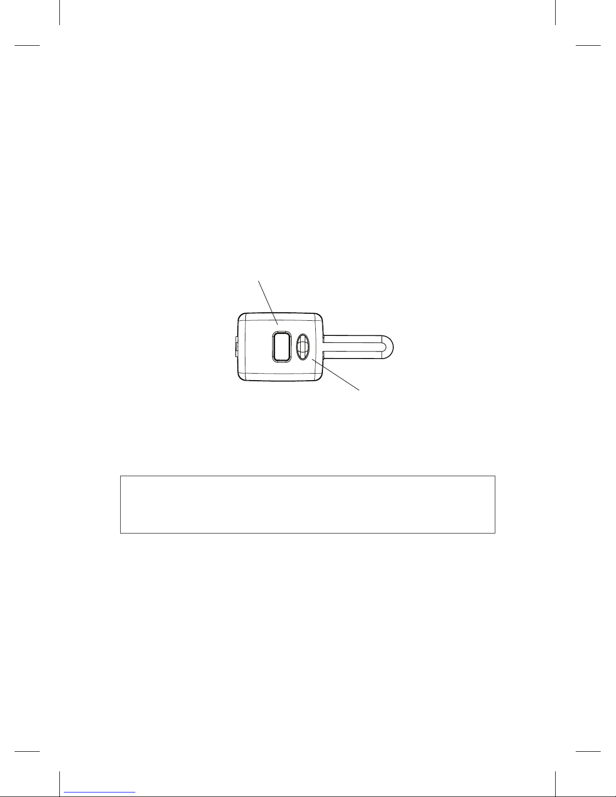
➤ The control center
The control center position should be discussed with the vehicle’s owner prior to
installation. The LED and Valet switch is housed on the control center, so you may
want to check that the customer is satisfied with the location.
Valet switch
LED
➤ Valet® program switch
The valet/program switch is built into the control center.
Important:
When the vehicle is delivered, please show the
user where this switch is lo cat ed and how to disarm the system with it.
Note: An optional valet switch (p/n #8631) is available if the onboard valet
switch is not used for the install.
When installing the external valet switch ensure that the location has sufficient
clearance to the rear. The switch should be well hidden. It should be placed so
pas sen gers or stored items (such as in a glove box or center console) cannot
accidentally activate it. The switch fits into a 9/32-inch hole.

9
© 2008 Directed Electronics. All rights reserved.
➤ Status LED
The status LED is built into the control center. An optional LED (p/n 8634)
is available if the onboard LED is not used for the install. The LED fits into a
9/32-inch hole.
➤ Doubleguard shock sensor
Since the shock sensor is built into the main unit, be sure to keep the shock sensor
performance in mind when deciding on a location for the main unit.
Note:
In many vehicles, fastening the main unit (the brain) to a steering column
or screwing it to metal will result in poor sensitivity, especially at the rear of the
vehicle.
➤ Before beginning the installation
Please read this entire installation guide before beginning the installation. •
The installation of this remote start system requires interfacing with many of
the vehicle’s systems. Many new vehicles use low-voltage or multiplexed
systems that can be damaged by low resistance testing devices, such as
test lights and logic probes (computer safe test lights). Test all circuits with a
high quality digital multi-meter before making connections.
Do not disconnect the battery if the vehicle has an anti-theft-coded radio. •
If equipped with an air bag, avoid disconnecting the battery if possible.
Many airbag systems display a diagnostic code through their warning
lights after they lose power. Disconnecting the battery requires this code to
be erased, which can require a trip to the dealer.
If using an external LED or Valet Switch, check with the customer about •
where to locate the switch.
To avoid accidental battery drainage; turn off the interior lights or remove •
the dome light fuse.
Roll down a window to avoid being locked out of the car.•
➤ After the installation
Test all functions. The “Using Your System” section of the Owner’s Guide is •
very helpful when testing.
When testing, don’t forget that this system is equipped with Nuisance •
Prevention® Circuitry (NPC). NPC can bypass trigger zones, making them
appear to stop working. See the Nuisance Prevention® Circuitry section

10
© 2008 Directed Electronics. All rights reserved.
in the owners guide.
Review and complete the Safety Check section of this guide prior to the •
vehicle reassembly.
Component locations and finding wires
For detailed information on where to locate components, and how to find the
wires you need, please refer to the Direct Tech web site at
www.directechs.
com.
Making your wiring connections
Before making your connections, plan how your wires are to be routed through
the vehicle. For instance, the red 12V constant input and the remote start ignition wires are often routed together to the ignition switch harness. In order to
keep the wiring neat and make it harder to find, you may wish to wrap these
wires together in electrical tape or conceal them in tubing similar to what the
manufacturer used.
There are two acceptable ways of making a wire connection - solder con nections and crimp connectors. When properly performed, either type of connection
is reliable and trouble-free. Regardless of whether you solder your connections
or you use mechanical type crimp-on connections, ensure that all connections
are mechanically sound and that they are insulated, especially when connecting
data lines in the vehicle.
Cheap electrical tape, especially when poorly applied, is not a reliable insulator. It often falls off in hot weather. Use good- quality electrical tape or heat
shrink.
Never twist-and-tape the wires together without soldering.•
Never use “fuse taps”, as they can damage fuse box terminals.•
If you use tapping connectors such as T-Taps (not to be confused with ScotchLocks), avoid using them in higher-current applications (constant 12V, ground,
etc.) These connectors are inferior in quality and should be avoided.
11
© 2008 Directed Electronics. All rights reserved.
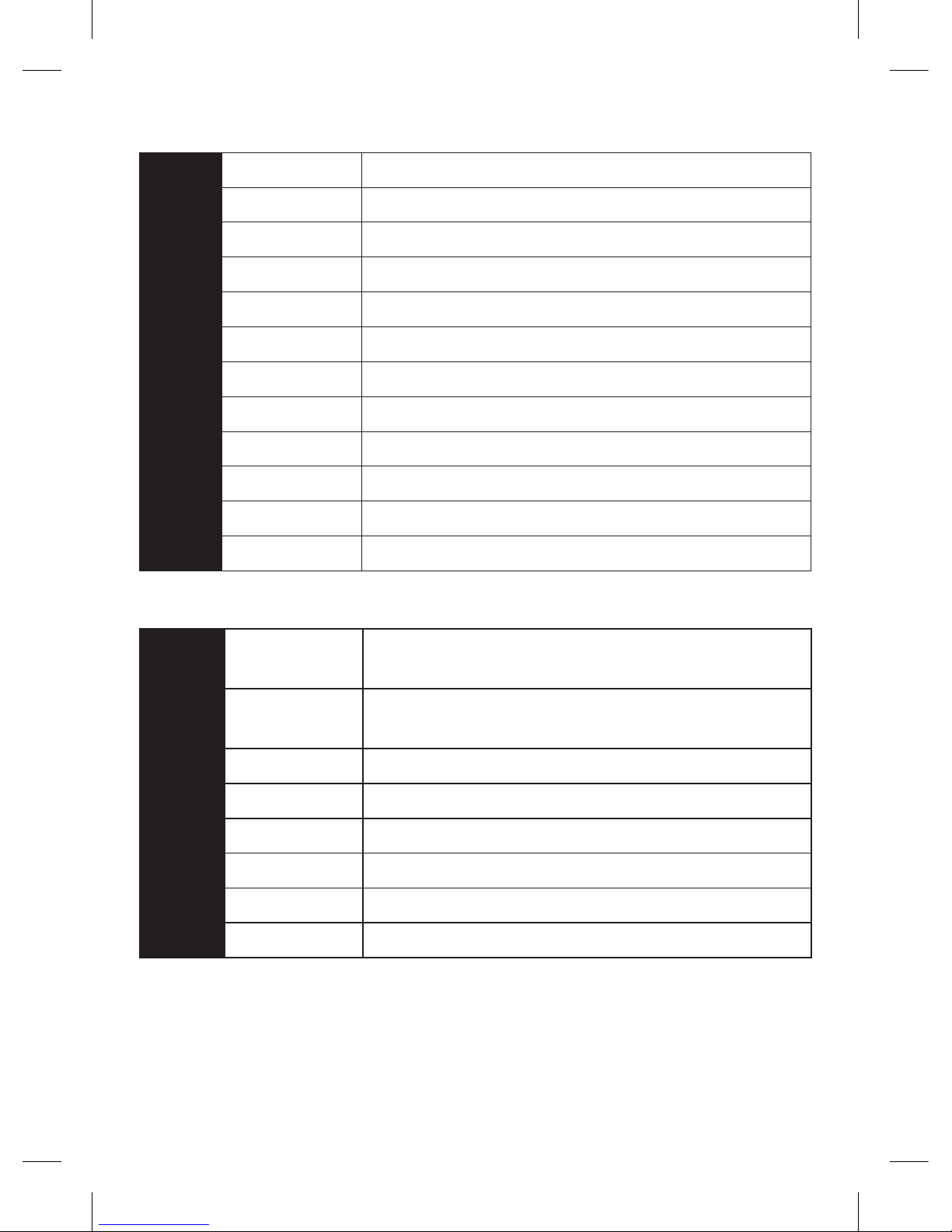
➤ Primary harness (H1), 12-pin connector
H1/1
RED/WHITE (-) 200mA TRUNK RELEASE OUTPUT
H1/2
RED (+)12v CONSTANT INPUT
H1/3
BROWN (+) SIREN OUTPUT
H1/4
WHITE/BROWN LIGHT FLASH ISOLATION WIRE - PIN 87a of onboard relay
H1/5
BLACK (-) CHASSIS GROUND
H1/6
VIOLET (+) DOOR TRIGGER INPUT
H1/7
BLUE (-) TRUNK PIN/ INSTANT TRIGGER INPUT (zone 1)
H1/8
GREEN (-) DOOR TRIGGER INPUT
H1/9
BLACK/WHITE (-) 200mA DOME LIGHT OUTPUT
H1/10
WHITE/BLUE (-) REMOTE START/ TURBO TIMER ACTIVATION INPUT
H1/11
WHITE PARKING LIGHT OUTPUT
H1/12
ORANGE (-) 500mA GROUND WHEN ARMED OUTPUT
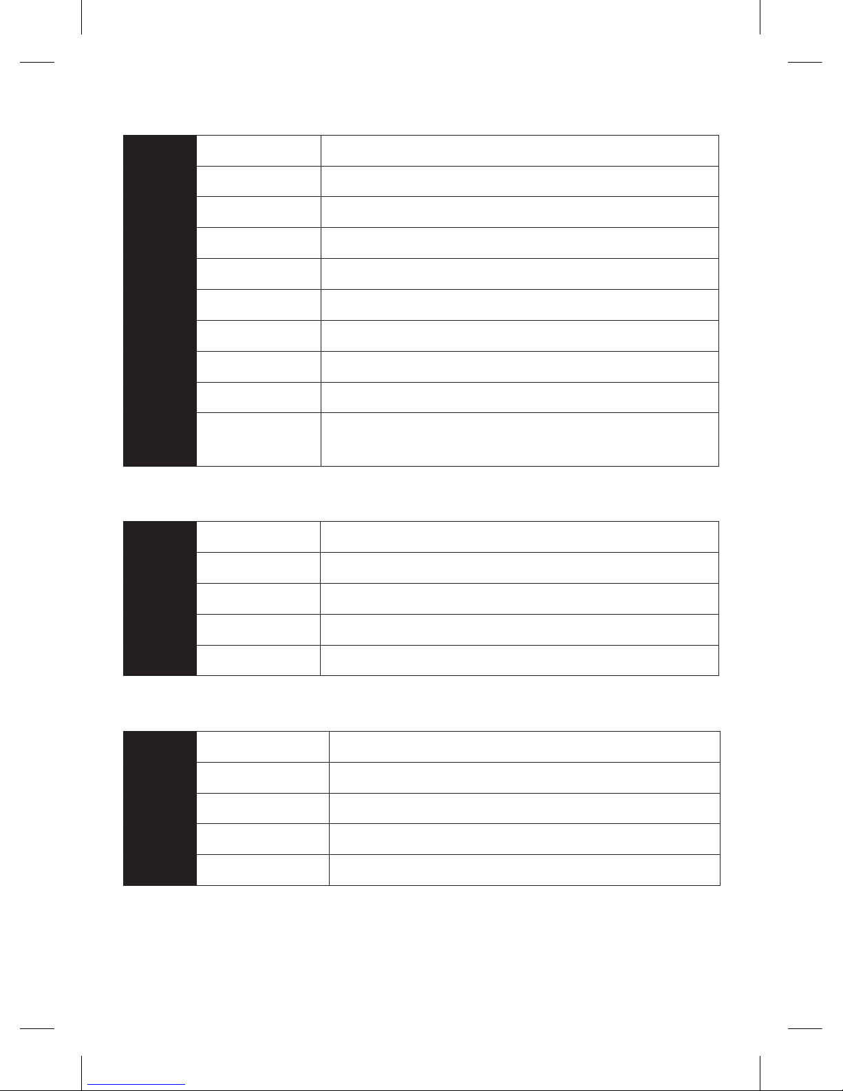
➤ Auxiliary harness (H2), 8-pin connector
H2/1
LIGHT GREEN/
BLACK
(-) 200mA FACTORY ALARM DISARM OUTPUT
H2/2
LIGHT GREEN/
WHITE
(-) 200mA FACTORY ALARM ARM OUTPUT
H2/3
WHITE/VIOLET (-) 200mA AUX 1 OUTPUT
H2/4
VIOLET/BLACK (-) 200mA AUX 2 OUTPUT
H2/5
WHITE/BLACK (-) 200mA AUX 3 OUTPUT
H2/6
LIGHT BLUE (-) 200mA 2ND UNLOCK OUTPUT
H2/7
GRAY/BLACK (-) DIESEL WAIT TO START INPUT
H2/8
BROWN/BLACK (-) 200Ma HORN HONK OUTPUT
There are three harness connections relative to remote start function, including
the heavy gauge and input and output harnesses.
12
© 2008 Directed Electronics. All rights reserved.
➤ Heavy gauge remote start, (H3) 10-pin connector
H3/1
PINK (+) IGNITION 1 INPUT/OUTPUT
H3/2
RED/WHITE (+) FUSED (30A) IGNITION 2 / FLEX RELAY INPUT 87
H3/3
ORANGE ACCESSORY OUTPUT
H3/4
VIOLET (+) STARTER OUTPUT (CAR SIDE OF THE STARTER KILL)
H3/5
GREEN (+) STARTER INPUT (KEY SIDE OF THE STARTER KILL WIRE)
H3/6
RED (+) FUSED (30A) IGNITION 1 INPUT
H3/7
PINK/WHITE (+) IGNITION 2 / FLEX RELAY OUTPUT
H3/8
PINK/BLACK FLEX RELAY INPUT 87A key side (if required) of FLEX RELAY
H3/9
RED/BLACK (+) FUSED (30A) ACCESSORY/STARTER INPUT
H3/10
NC (no connection)
NC
➤ Remote start input, 5-pin connector
1
BLACK/WHITE (-) NEUTRAL SAFETY SWITCH INPUT
2
VIOLET/WHITE TACHOMETER INPUT WIRE
3
BROWN (+) BRAKE SHUTDOWN INPUT WIRE
4
GRAY N/O or N/C (-) HOOD PIN SWITCH INPUT, ZONE 6
5
BLUE/WHITE (-) 200 mA 2ND STATUS/REAR DEFOGGER OUTPUT
➤ Remote start auxiliary output, 5-pin
1
PINK/WHITE (-) 200mA FLEX RELAY CONTROL OUTPUT
2
ORANGE (-) 200mA ACCESSORY OUTPUT
3
VIOLET (-) 200mA STARTER OUTPUT
4
PINK (-) 200mA IGNITION 1 OUTPUT
5
BLUE (-) 200mA STATUS OUTPUT
Note: Wires 1 - 4 on the remote auxiliary outputs are wired to the (-) triggers for
the onboard remote start relays and are not diode isolated. If connecting these
13
© 2008 Directed Electronics. All rights reserved.
wires directly to the vehicle you must place a 1-amp diode in line to prevent
feedback from the vehicle.
➤ Door lock harness, 3-pin connector
1
BLUE (+) LOCK (-) UNLOCK OUTPUT
2
EMPTY NOT USED
3
GREEN (-) LOCK (+) UNLOCK OUTPUT
14
© 2008 Directed Electronics. All rights reserved.
Wire connection guides
➤ Primary harness (H1)
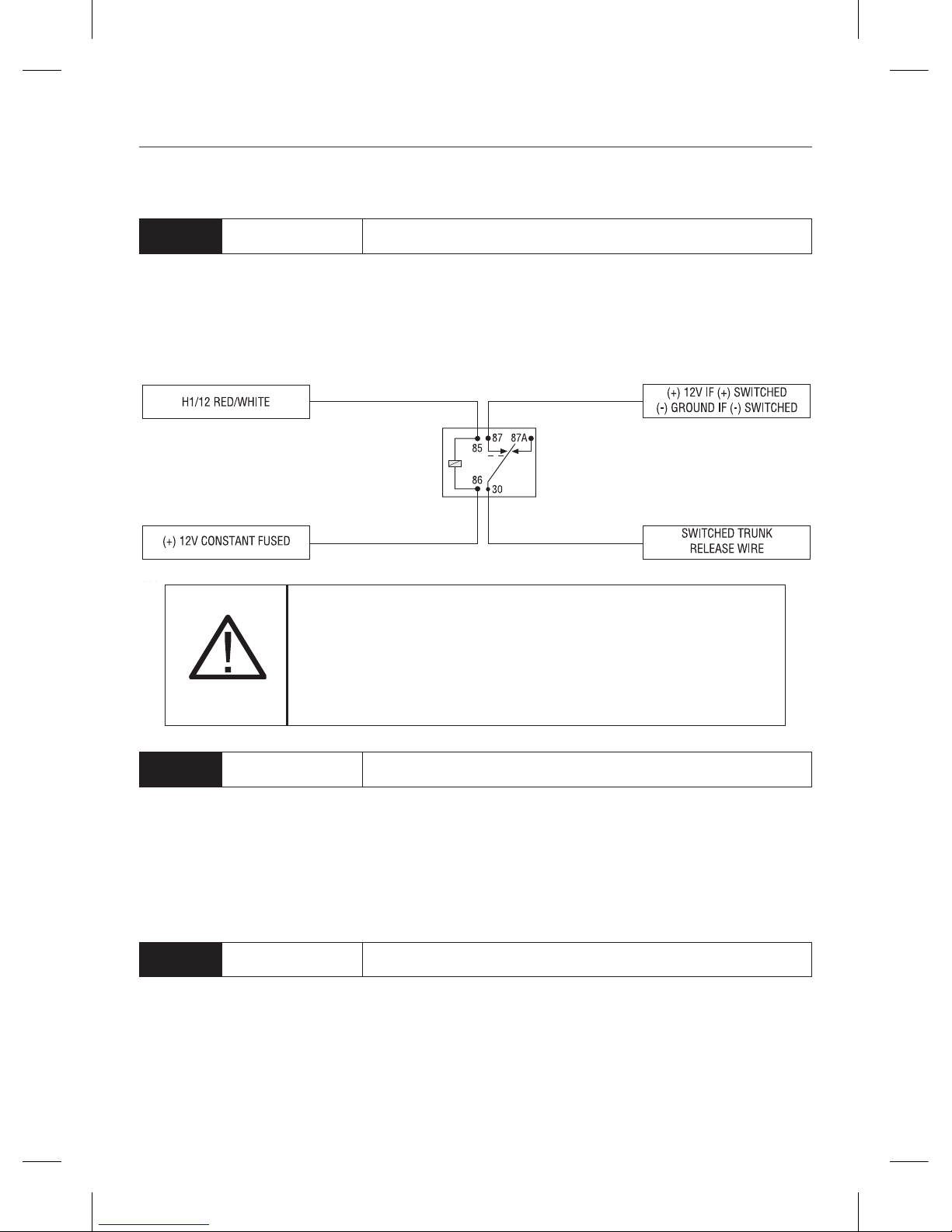
H1/1
RED/WHITE (-) 200mA TRUNK RELEASE OUTPUT
When the system receives the code controlling trunk release output for longer
than 1.5 seconds, the red/white wire supplies an output as long as the transmission continues. This is typically used to operate a trunk/hatch release or other
relay-driven function.
Warning!
Never use this wire to drive anything but
a relay or a low-current input! The transistorized output can only supply 200mA of current. Connecting
directly to a solenoid, motor, or other high-current
device will cause it to fail.
H1/2
RED (+)12v CONSTANT INPUT
Before connecting this wire, remove the supplied fuse. Connect to the battery
positive terminal or the constant 12V supply to the ignition switch.
Note:
Always use a fuse within 12 inches of the point you obtain (+)12V. Do not
use the 15A fuse in the harness for this purpose. This fuse protects the module.
H1/3
BROWN (+) SIREN OUTPUT
Connect this to the red wire of the siren . Connect the black wire of the siren
to (-) chassis ground, preferably at the same point you connected the control
module's black ground wire.
15
© 2008 Directed Electronics. All rights reserved.
H1/4
WHITE/BROWN LIGHT FLASH -ISOLATION WIRE - PIN 87a of onboard relay
This wire connects to pin 87a of the onboard light flash relay. It is used whenever light switch isolation on the vehicle is necessary. If the vehicle has a multiplex circuit that needs the light switch isolated, you can remove the onboard
light flash fuse and replace it with the specified resistor (paying attention to the
polarity selection).
xx
Lightswitch
Multiplex
wire in car
White/Brown
White
Cut
Replace fuse with
specied resistor value
Light Flash Fuse
Jumper under door
To control
module in car
Multiplex Lightash Interface
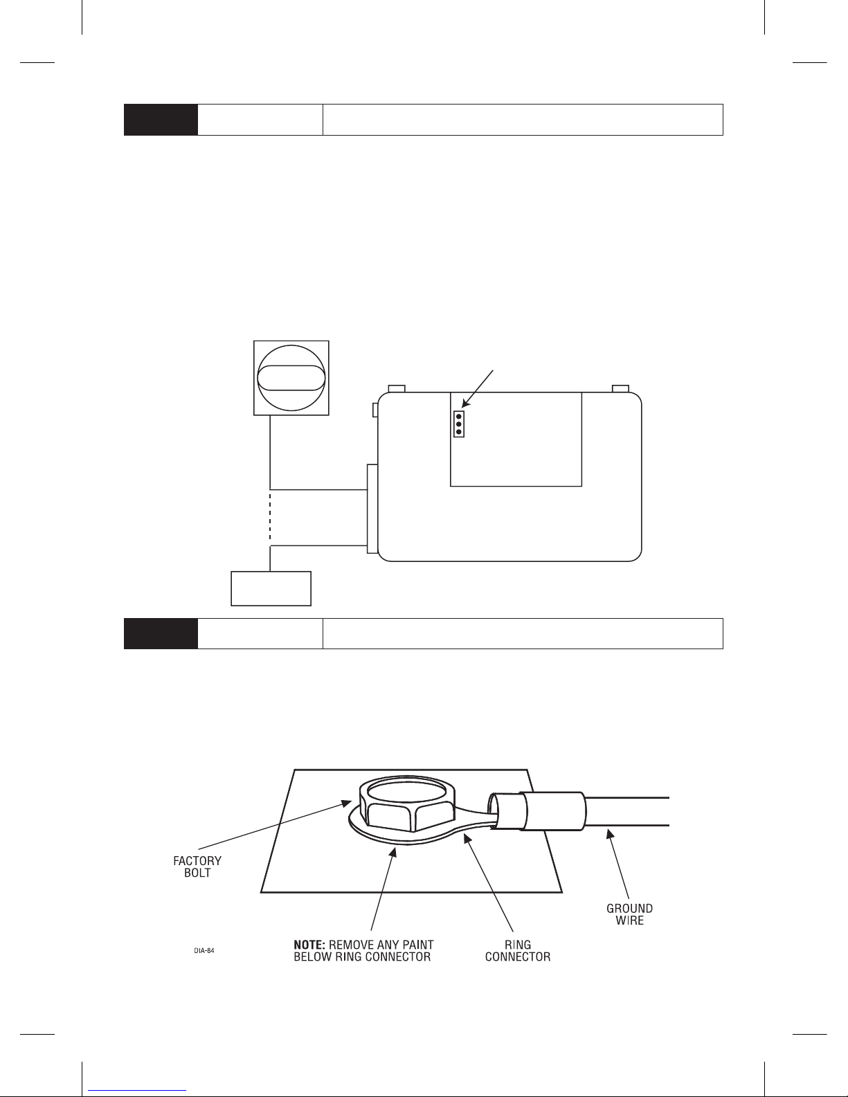
H1/5
BLACK (-) CHASSIS GROUND
We recommend that you do not use a factory ground. Ground all your components to the same point in the vehicle, (preferably the kick panel). Scrape away
any paint and use a factory bolt or make your own ground with a self-tapping
screw and a star washer.
16
© 2008 Directed Electronics. All rights reserved.
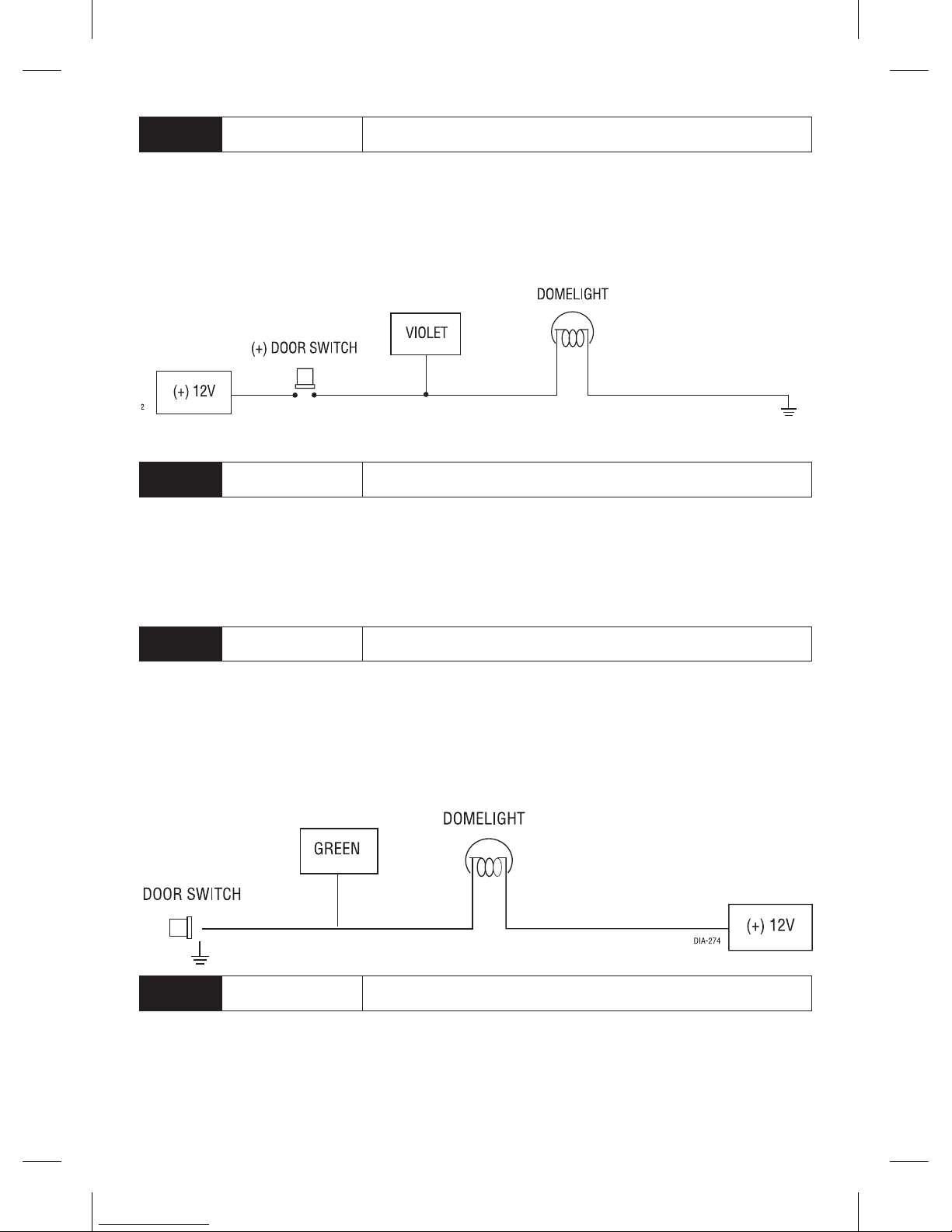
H1/6
VIOLET (+) DOOR TRIGGER INPUT
This wire is used in vehicles that have a positive (+) switched dome light circuit.
Connect the violet wire to a wire that shows (+)12V when any door is opened,
and ground when the door is closed.
H1/7
BLUE TRUNK PIN / INSTANT TRIGGER INPUT
This input responds to a negative input with an instant trigger. This is ideal for
a trunk pin. It can also be used with Directed single-stage sensors and reports
on Zone 1.
H1/8
GREEN (-) DOOR TRIGGER INPUT
Most vehicles use negative door trigger circuits. Connect the green wire to a
wire which shows ground when any door is opened. In vehicles with factory
delays on the dome light circuit, there is usually a wire that is unaffected by the
delay circuitry.
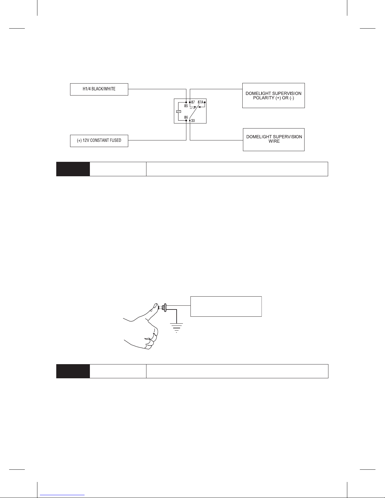
H1/9
BLACK/WHITE (-) 200mA DOME LIGHT OUTPUT
Connect this wire to the optional dome light supervision relay as shown below:
Important! This output is only intended to drive a relay. It cannot be connected
17
© 2008 Directed Electronics. All rights reserved.
directly to the dome light circuit, as the output cannot support the current draw
of one or more light bulbs.
H1/10
WHITE/BLUE (-) REMOTE START/ TURBO TIMER ACTIVATION INPUT
This input comes from the factory set to 1 activation pulse. This means that it is
necessary to have a single ground pulse on the white/blue wire for the remote
start to activate or to deactivate.
The H1/10 wire can also be used to activate the Turbo Timer mode when the
car is running and this wire receives a ground.
Note:
The number of activation inputs can be programmed to 1 or 2 pulses with
an optional momentary switch. This setting affects both the input wire and the
remote control when operating the remote starter.
To white/blue activation
input on system
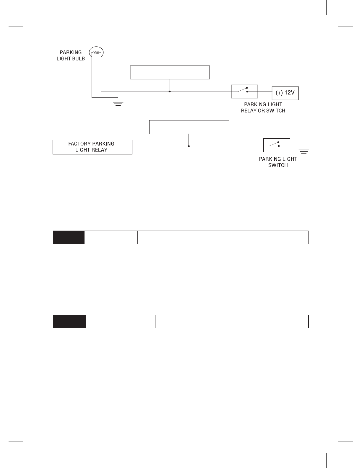
H1/11
WHITE PARKING LIGHT OUTPUT
This wire should be connected to the parking light wire in the vehicle. See Setting the light flash polarity section of this guide for polarity settings.
18
© 2008 Directed Electronics. All rights reserved.
(+) Positive Light Flash Output
(-) Negative Light Flash Output
WHITE H1/11
(+) LIGHT FLASH OUTPUT
WHITE H1/11
(-) LIGHT FLASH OUTPUT
Note: For parking light circuits that draw 10-amps or more, the internal jumper
must be switched to a (-) light flash output. (See Setting the light flash polarity
section of this guide.) P/N 8617 or a standard automotive SPDT relay must be
used on the H1/11 light flash output harness wire.
H1/12
ORANGE (-) 500mA GROUND WHEN ARMED OUTPUT
This wire supplies a (-)500 mA ground as long as the system is armed. This
output ceases as soon as the system is disarmed. The GWA can be hooked up
to a window module, a voice module or any accessory that requires a ground
when armed.
➤ Auxiliary harness (H2)
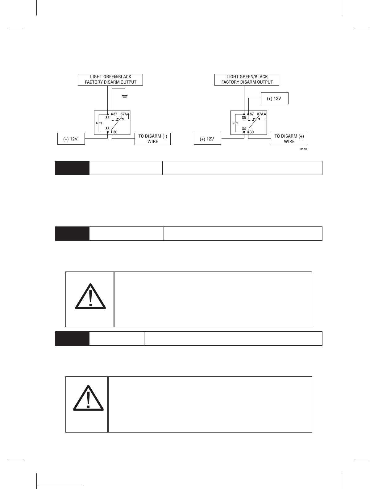
H2/1
LIGHT GREEN/BLACK (-) 200mA FACTORY ALARM DISARM OUTPUT
This wire sends a negative pulse every time the remote start is activated , channel 2 is activated (programmable on/off) or when the doors are unlocked with
the remote. This can be used to pulse the disarm wire of the vehicle’s factory antitheft device. Use a relay to send a (-) or (+) pulse to the disarm wire as shown
in the following diagrams.
19
© 2008 Directed Electronics. All rights reserved.
Relay for Negative (-) Disarm Wire Relay for Positive (+) Disarm Wire
H2/2
LIGHT GREEN/WHITE (-) 200mA FACTORY ALARM ARM OUTPUT
This wire sends a negative pulse every time the remote start shuts down or when
the doors are locked with the remote. This can be used to pulse the arm wire
of the vehicle’s factory anti-theft device. Use a relay to send a (-) or (+) pulse to
the arm wire.
H2/3
WHITE/VIOLET (-) 200mA AUX 1 OUTPUT
This wire provides 200 mA programmable output whenever the transmitter buttons controlling Aux 1 channel is pressed. (See descriptions for Aux 3)
Warning!
Never use this wire to drive anything
but a relay or a low-current input! This transistorized output can only supply 200 mA. Connecting
directly to a solenoid, motor, or other high-current
device will cause the module to fail.
H2/4
VIOLET/BLACK (-) 200mA AUX 2 OUTPUT
This wire provides 200 mA programmable output whenever the transmitter buttons controlling Aux 2 channel is pressed. (See descriptions for Aux 3.)
Warning! Never use this wire to drive anything but
a relay or a low-current input! This transistorized output can only supply 200 mA. Connecting directly to
a solenoid, motor, or other high-current device will
cause the module to fail.
20
© 2008 Directed Electronics. All rights reserved.
H2/5
WHITE/BLACK (-) 200mA AUX 3 OUTPUT
This wire provides 200 mA programmable output whenever the transmitter
button(s) controlling Aux 3 is pressed. This output can be programmed to provide
the following types of outputs
Validity: Output that sends a signal as long as the transmission is re-•
ceived.
Latched: Output that sends a signal when the Aux channel button is pressed •
and continues until the same button is pressed.
Latched, reset with ignition: Similar to the latched output, this type of output •
turns On the first time the Aux channel button is pressed, and turns Off the
next time the same button is pressed. This type of output additionally stops
and resets whenever the ignition is turned On and then Off.
30 seconds timed: The output sends a continuous signal for 30 seconds.•
Note: Bitwriter® programs from 1 to 90 seconds.
Warning! Never use this wire to drive anything but
a relay or a low-current input! This transistorized output can only supply 200 mA. Connecting directly to
a solenoid, motor, or other high-current device will
cause the module to fail.
H2/6
LIGHT BLUE (-) 200mA 2ND UNLOCK OUTPUT
This wire produces a (-) 200mA output for progressive locks in which the driver
door unlocks first and the remaining locks unlock with a second press of the
unlock button on the remote.
Note:
This feature needs to be programmed “On” to function correctly (see
System Feature Menu #1, feature #8).
H2/7
GRAY/BLACK (-) DIESEL WAIT TO START INPUT
Connect this wire to the wire in the vehicle that sends the signal to turn on the
 Loading...