

Page 1
AS530R
USER MANUAL
Model: 50000417
VR28016
Rev.01
2016.10.24
Nilfisk Inc.
9435 Winnetka Avenue North
Minneapolis, MN 55445
www.usviper.com
Page 2

TABLE OF CONTENTS
ENGLISH
USER MANUAL…………………………………………………………………….
1-21
FRANÇAIS
MANUEL UTILISATEUR…………………………………………………………
22-42
ESPAÑ OL
INSTRUCCIONES DE USO……………………………………………………..
43-63
Page 3

USER MANUAL ENGLISH
TABLE OF CONTENTS
INTRODUCTION ............................................................................................................................ 1
MANUAL CONTENT AND PURPOSE ....................................................................................................................................... 1
HOW TO KEEP THIS MANUAL ................................................................................................................................................ 1
DECLARATION OF CONFORMITY ............................................................................................................................................ 1
ACCESSORIES AND MAINTENANCE ........................................................................................................................................ 1
CHANGES AND IMPROVEMENTS ........................................................................................................................................... 1
SCOPE OF APPLICATION ......................................................................................................................................................... 1
MACHINE IDENTIFICATION DATA .......................................................................................................................................... 1
TRANSPORT AND UNPACKING ............................................................................................................................................... 1
SAFETY ............................................................................................................................................................ 2
SYMBOLS THAT APPEAR ON THEINSTRUCTION FOR USE MANUAL ...................................................................................... 2
GENERAL SAFETY INSTRUCTION ............................................................................................................................................ 2
MACHINE DESCRIPTION................................................................................................................ 4
MACHINE STRUCTURE ........................................................................................................................................................... 4
CONTROL PANEL .................................................................................................................................................................... 5
LED SCREEN DISPLAY INFORMATION ..................................................................................................................................... 5
DISPLAY WINDOW OF CHARGER INDICATON LIGHT ............................................................................................................. 5
TECHNICAL PARAMETERS ...................................................................................................................................................... 6
CIRCUIT DIAGRAM ................................................................................................................................................................. 7
OPERATING GUIDE ....................................................................................................................... 9
INSTALLING AND SETTING OF NEW MACHINE BATTERY ....................................................................................................... 9
BATTERY INSTALLATION AND BATTERY TYPE SETTING (WET OR GEL/ AGM) ........................................................................ 9
EMERGENCY BRAKING ......................................................................................................................................................... 10
BRUSH/PAD INSTALLATION AND UNINSTALLATION ............................................................................................................ 10
ADJUSTING THE BALANCE OF SQUEEGEE ............................................................................................................................ 11
SOLUTION TANK FILLING ..................................................................................................................................................... 11
MACHINE START AND STOP ................................................................................................................................................. 12
MACHINE OPERATION (SCRUBBING AND DRYING) ............................................................................................................. 13
TANK EMPTYING .................................................................................................................................................................. 14
AFTER USING THE MACHINE ................................................................................................................................................ 14
MACHINE LONG INACTIVITY ................................................................................................................................................ 14
USING FOR THE FIRST TIME ................................................................................................................................................. 15
MAINTENANCE ........................................................................................................................... 15
SCHEDULED MAINTENANCE TABLE ..................................................................................................................................... 15
BATTERY CHARGING ............................................................................................................................................................ 15
BRUSH/PAD CLEANING ........................................................................................................................................................ 16
SOLUTION FILTER CLEANING ............................................................................................................................................... 17
SQUEEGEE CLEANING .......................................................................................................................................................... 17
SQUEEGEE BLADE CHECK AND REPLACEMENT .................................................................................................................... 17
TANK AND VACUUM GRID WITH FLOAT CLEANING, AND COVER GASKET CHECK .............................................................. 18
FUSE CHECK/REPLACEMENT ................................................................................................................................................ 19
ACCESSORIES/OPTIONS ....................................................................................................................................................... 19
TROUBLE SHOOTING .................................................................................................................. 19
SCRAPPING ................................................................................................................................ 21
Page 4

USER MANUAL ENGLISH
1
INTRODUCTION
NOTE
The numbers in brackets refer to the components shown in Machine Description chapter.
MANUAL CONTENT AND PURPOSE
The purpose of this Instruction for Use Manual is to provide the operator with necessary information to use the
machine properly and safely. It contains information about technical data, safety, operation, storage, maintenance,
spare parts and how to scrap it.
Before performing any procedure on the machine, no matter the operators and qualified technicians must read this
Manual carefully. Contact our company’s service center for any query about this manual or for any further information
is needed.
The operators must not perform procedures that should be done by qualified technicians. Our company will not be
answerable for damages coming from the non-observance of this prohibition.
HOW TO KEEP THIS MANUAL
The Manual must be kept near the machine, inside an adequate case, away from liquids and other substances that can
cause any damage to it.
DECLARATION OF CONFORMITY
Declaration of Conformity is supplied with the machine and certifies machine conformity with the law in force.
NOTE
The copies of the original declaration of conformity are provided together with the machine
documentation.
ACCESSORIES AND MAINTENANCE
All the necessary operation, maintenance and repair procedures must be performed by qualified personnel, or by our
company appointed service center. ONLY authorized spare parts and accessories should be used.
Contact our company customer service for any service or purchase of accessories or spare parts if necessary.
CHANGES AND IMPROVEMENTS
We committed to continuous improvement of the products, the company reserves the right to the machine changes
and improvements without informing in additional.
SCOPE OF APPLICATION
The scrubber applies to commercial and industrial use. It is suitable for cleaning smooth and solid floors, operating by a
qualified personnel in safety circumstance. It is not suitable for outdoor use, carpet or rough floor cleaning.
MACHINE IDENTIFICATION DATA
The machine serial number and model name are marked on the serial label.
This information is useful. Use the following table to write down the machine identification data when requiring spare
parts for the machine.
MACHINE MODEL....................................................................................
MACHINE SERIAL NUMBER......................................................................
TRANSPORT AND UNPACKING
When the carrier delivers the machine, make sure the packaging and machine are both whole and undamaged. If any
damaged, make the carrier know the damage and before accepting the goods, reserve the right in compensation of the
damage.
Follow the instructions on packing strictly when unpacking the machine.
Check the package to ensure following items are included:
Page 5
USER MANUAL ENGLISH
2
1. Technical documentations including user manual, and on-board charger manual if on-board charger is equipped.
2. Charger cable if on-board charger is equipped.
SAFETY
The following symbols indicate potentially dangerous situations. Always read this information carefully and take all
necessary precautions to safeguard people and property.
SYMBOLS THAT APPEAR ON THEINSTRUCTION FOR USE MANUAL
DANGER!
It indicates a dangerous situation with risk of death for the operator.
WARNING!
It indicates a potential risk of injury for people.
CAUTION!
It indicates a caution or a remark related to important or useful functions.
Pay attention to the paragraphs marked by this symbol.
NOTE
It indicates a remark related to important or useful functions.
CONSULTATION
It indicates the necessity to refer to the Instruction for Use manual before performing any procedure.
GENERAL SAFETY INSTRUCTION
Specific warnings and cautions to inform about potential damages to people and machine are shown below.
DANGER!
This machine must be operated by trained and authorized personnel according to guidance of the manual.
Before performing any cleaning, maintenance, repair or replacement procedure, read all the instructions
carefully, ensure to turn the machine OFF and disconnect the battery connector.
Do not operate the machine near toxic, dangerous, flammable and/or explosive powders, liquids or vapour.
This machine is not suitable for collecting dangerous powders.
Do not wear jewels when working near electrical components.
Do not work under the lifted machine without supporting it with safety stands.
When using lead (WET) batteries, they may emit inflammable gas under normal use, must keep sparks,
flames, smoking materials and radiating, illuminating and burning items away from the batteries.
When charging lead (WET) batteries, they may emit hydrogen gas which may cause explosive. Must ensure
the charging environment is well ventilated and away from naked flames.
WARNING!
Check the machine carefully before each use. Ensure that all the components have been well assembled
before use. Or it may causes damages to people and properties.
Page 6

USER MANUAL ENGLISH
3
Before using the battery charger, ensure that the values of frequency and voltage indicated on the machine
serial number label match those of mains.
Never move the machine by pulling the battery charger cable. Do not let the cable through a closed door, or
winding on sharp edges or corners. Do not run the machine on the battery charger cable. Keep the battery
charger cable away from heated surfaces.
Do not charge the batteries if the battery charger cable or the plug are damaged.
To reduce the risk of fire, electric shock, or injury, make sure machine is off before leaving.
Use or store the machine indoors in dry conditions, it is not allowed for outdoor use.
The machine both storage and working temperature must be between 0 °C and +40 °C, the humidity of air
must be between 30% - 95%.
Do not use the machine on slopes with a gradient exceeding as specification show.
When using and handling floor cleaning detergents, follow the instructions on the labels of the detergent
bottles and wear suitable gloves and protections.
Use brushes and pads supplied with the machine or defined in the manual. Using other brushes or pads
could reduce safety.
In case of machine malfunctions, ensure that these are not due to lack of maintenance. If necessary, request
assistance from the authorized personnel or from an authorized Service Center.
Take all necessary precautions to prevent hair, jewels and loose clothes from being caught by the machine
moving parts.
Do not use the machine in particularly dusty areas.
Do not wash the machine with direct or pressured water jets, or with corrosive substances.
Do not bump into shelves or scaffoldings, especially where there is a risk of falling objects.
Do not lean liquid containers on the machine, use the relevant can holder.
To avoid damaging the floor, do not allow the brush/pad to operate while the machine is stationary.
In case of fire, use a dry powder fire extinguisher. Do not use liquid fire extinguishers.
Do not remove or modify the machine stickers.
Do not tamper with the machine safety guards and follow the ordinary maintenance instructions
scrupulously.
Pay attention during machine transportation when temperature is below freezing point. The water in the
recovery tank and in the hoses could freeze and cause seriously damage to the machine.
If spare parts need be replaced, order ORIGINAL spare parts from an Authorized Dealers or Retailers.
Return the machine to the Service Center if it doesn’t work as usual or it is in condition such as damaged,
placed outdoors, dropped into water.
To ensure machine proper and safe operation, the scheduled maintenance shown in the relevant chapter of
this Manual, must be performed by the authorized personnel or an authorized Service Center.
The machine must be properly disposed of, because the presence of toxic-harmful materials (batteries, etc.),
which are subject to standards that require disposal in special centers (see Scrapping chapter).
This machine as a cleaning tool only, not for any other purpose use.
Always keep the openings free from dust, hairs and any other foreign material which could reduce the
airflow. Do not use the machine if the openings are clogged.
Use the machine only where a proper lighting is provided.
This machine is not intended for use by persons with reduced physical, sensory or mental capabilities, or lack
of experience and knowledge, unless they have been given supervision or instruction concerning use of the
machine by a person responsible for their safety.
Close attention is necessary when used near children.
Children should be supervised to ensure that they do not play with the machine.
While using this machine, take care not to cause damage to people or objects.
Page 7
USER MANUAL ENGLISH
4
MACHINE DESCRIPTION
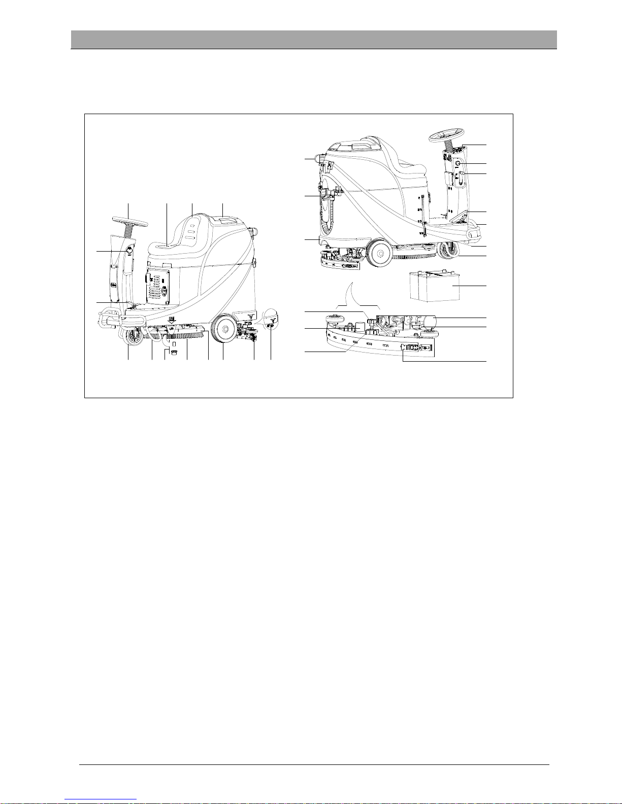
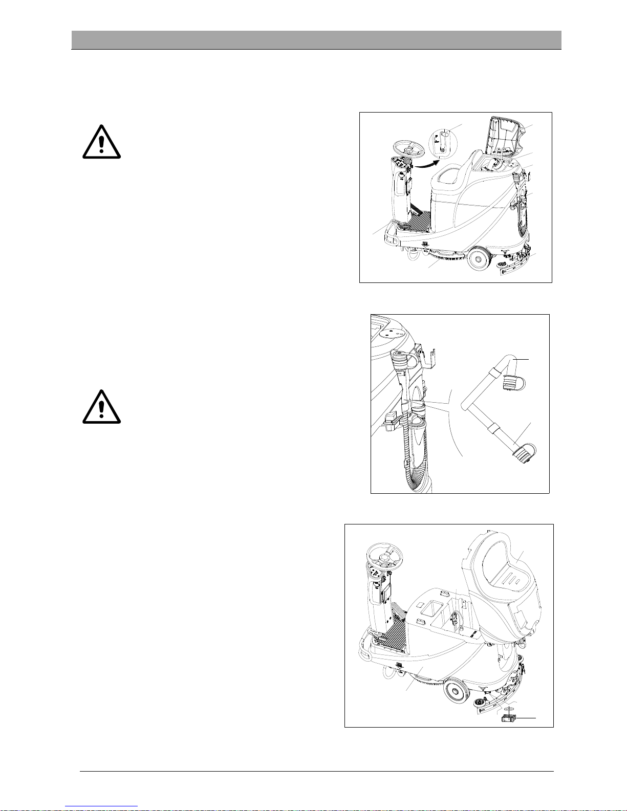
MACHINE STRUCTURE (as shown in Figure 1)
1. Steering wheel
2. Seat cushion
3. Recovery tank
4. Recovery tank cover
5. USB charging port
6. Pedal
7. Front wheel
8. Left support bracket
9. Solution Filter
10. Brush
11. Brush deck
12. Rear wheel
13. Squeegee assembly
14. Solution outlet cover
15. Sewage drain hose
16. Water inlet cover
17. Solution tank
18. Squeegee adjustment knob
19. Vacuum hose
20. Squeegee knob
21. Control panel
22. Emergency switch
23. Squeegee lifting/lowering lever
24. Accelerate pedal
25. Front bumper
26. Solution level indicator
27. Right support bracket
28. Battery
29. Drive motor
30. Brake block bracket
31. Squeegee hasp
1
2 3 4
5
6
7
8
9 10 11 12
13 14
15
16
17
18
19
21
22
23
24
25
26
27
28
29
30
31
20
Figure 1
Page 8
USER MANUAL ENGLISH
5
MACHINE DESCRIPTION
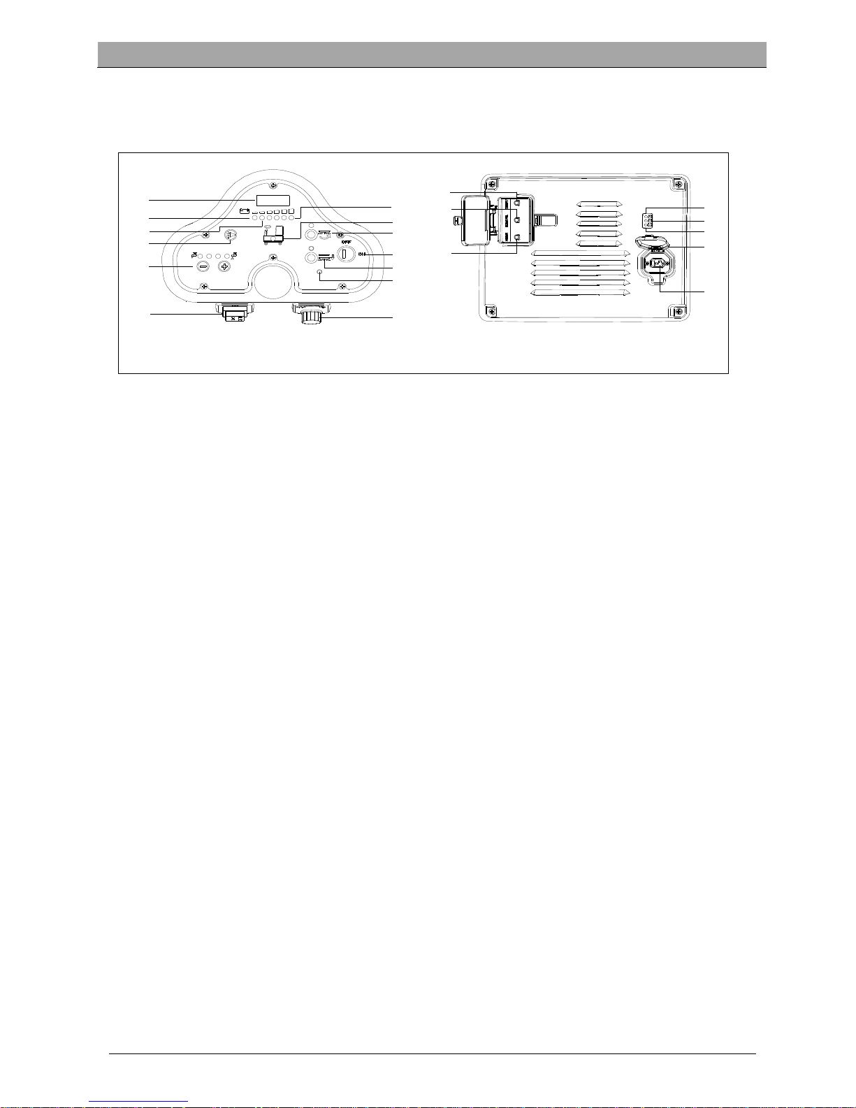
CONTROL PANEL (as shown in Figure 2)
31. LED screen
32. Discharged battery warning light (Red)
33. Battery semi-discharged indicator (Yellow)
34. Horn button
35. Solution volume adjusting button
36. Forward-Backward switch
37. Battery fully charged indicator (Green)
38. Solution tank empty indicator
39. Brush button
40. Key switch
41. Brush unload button
42. Drive motor trouble light
43. Speed adjusting knob
44. Vacuum motor overload protector
45. Drive motor overload protector
46. Brush motor overload protector
47. Battery charge indicator (Red)
48. Battery semi-charged indicator (Yellow)
49. Battery fully charged indicator (Green)
50. Charger plug cover
51. Charger plug
LED SCREEN DISPLAY INFORMATION
STOP– Machine cannot move, brush stops working but vacuum motor can work
(00012.3) – Total working hours of machine are 12.3hours
L0-(18) – Battery voltage lower than 18V
U-(25.5) – Battery voltage is 25.5V
ERR-01 – Squeegee is not lifted when machine turns backward
DISPLAY WINDOW OF CHARGER INDICATON LIGHT (as shown in Figure 2)
1. At the beginning of charging, the Yellow LED (48) twinkles, the red LED (47) and green LED (49) turn on for a second,
on the red LED turns off, and then the green LED twinkles a few times before the red LED on charger is normally. It
is the first stage of charging.
2. After charging for some time, the red LED (47) on charger turns off, the yellow LED (48) turns on, this is the second
stage of charging.
3. When charging is completed, the yellow LED (48) turns off, the green LED (49) turns on to indicate that the battery
is fully charged.
NOTE
In the process of charging, if the yellow light (48) is on, it may be caused by: Battery and charger doesn’t
match, battery is not connected well, or output is short-circuited.
The red light of charger flashing may be caused by the charger internal short circuit.
42
31
32
35
36
38
39
40
41
43
37
33
44
45
47
48
34
50
46
49
51
Figure 2
Page 9

25
USER MANUAL ENGLISH
6
TECHNICAL PARAMETERS
MODEL AS530R
Packing dimensions (Lx W x H) mm 1470*730*1310
Machine height mm 1120
Machine length mm 1360
Machine width (without squeegee) mm 580
Machine weight with empty tanks
(without batteries)
Kg 140
Gross vehicle weight (GVW) Kg 270
Shipping weight Kg 245
Solution tank capacity Liter 72
Recovery tank capacity Liter 73
Vacuum motor power Watt 400
Vacuum capacity mm H₂O 1223
Climbing capacity (Max) % 10
Front wheel diameter mm φ175
Rear wheel diameter mm φ230
Sound level dB(A) 69
Solution/water Flow L/min 0.84-2.0
Working width mm 530
Squeegee width mm 730
Brush/pad diameter mm 530
Brush motor power Watt 450
Brush speed Rpm 160
Brush/pad pressure (Max) Kg
Drive motor power Watt 300W
Working speed Km/h 5.5km/h
Voltage V 24V
Battery Ah 2x100AH (20 hours)
Battery charger V/A 24V 10A
Battery compartment size (L x W x H) mm 350*380*300
USB charger specification V/A 5V, 0.8A
Page 10

USER MANUAL ENGLISH
7
CIRCUIT DIAGRAM
C
U
RTIS 1212
M1
M1
B+
B-
2
4
3
1
J1
J2
SPK
BU2
BN2
6
2
7
384
9
5
10
1
EB1
5
1
6
2
7
3
8
4
1
2
J3
SW
1
AC
DC
+
_
NC
F
2
30A
R
L1
R
L2
YV
R
L3
SQ
+
_
7
6
5
4
3
2
1
14
13
12
11
10
2
1
8
9
M
EB2
VR
KA
J4
J5
M
M
F3
30A
F4
30A
BAT
24V
F1
5
A
F5 20A
W
H
1
WH1
WH1
RD2
RD2
RD2
RD3
RD1
BK1 BK3 BK2 BK3
RD4
RD/BK
RD/BK
RD/BK
RD3
RD4
BK5
BK5
YEYE YERD4
BN/BK
BU/BK
BN2
BK5
BK5
BK
5
OR
W
H2
BN1
BN1
BN1
YE
WH2
GN/BK
OR
SW7
RD4
SW6-A
YE
YE
PU
BK5
BK4
BU/BK
RD4
BN2
OR
GN
PU
GY
BN
1
BK4
SW2
M2
M1
M3
BK5
BK5
SW
3
SW
4
SW
6-
B
RL3
RL2
RL1
OR
GY
CH
RD4
100K
3
SW
5
BU
1
RD4
EB3
BK5
RD4
BK5
1
+
PU
WI
R
E ROD
RD1
RD2
RD3
BK1
BK2
RED/6AWG
RED/10AWG
RED/18AWG
BLACK/6AWG
BLACK/10AWG
RD/BK RED/BLACK / 20AWG
BN1 BROWN/14AWG
BN2 BROWN/20AWG
BK4 BLACK/14AWG
BK5
BLAC
K/18
AWG
BK3
BLAC
K/12
AWG
SW2
SW3
SW1
M1
M2
M3
BR
USH MOTOR
VACUUM MOTOR
DRIVE MOTOR
CLEAN WATER LEVEL SWITCH
VACUUM MOTOR SWITCH
KEY SWITCH
COMPONENTS
VR SPEED POTENTIOMETER
F
OO
T THROTTLE
SQ
EMERGENCY-STOP SWITCH
SW4
SW5 OPT
ION
AL MODE SWITCH
OPTIONAL REVERSE SWITCH SW6-B
OPT
ION
AL REVERSE SWITCH SW6-A
SPK 12VDC BUZZER
KA BR
A
KE
SW7
SEAT
S
WITCH
BA
T
C
H
EB1
EB3
F1
F2
F3
RL1
RL2
24V BAT
T
ERIES
BATTERY CHARGER
CONTROL PANEL BOARD
BRUSH MOTOR CIRCUIT BREAKER
VACUUM MOTOR CIRCUIT BREAKER
BRUSH MOEOR ELECTROM SWITCH
DRIVE ELECTRONIC BOARD
VACUUM MOEOR ELECTROM SWITCH
DRIVE SYSTEM CIRCUIT BREAKER F4
YV WATER ELECTROVALVE
CONTROL PANEL BOARD FUSE
COMPONENTS
R
L
3
DRIVE SYSTEM ELECTROM SWITCH
EB2
U
SB CHARGING ELECTRONIC BOARD
BR
U
SH RELEASE FUSE
F5
WI
R
E ROD
GN GREEN/20AWG
GN/BK
GREEN/BLACK /20AWG
BN/BK BROWN/BLACK / 20AWG
BU/BK BLUE/BLACK / 20AWG
PU PURPLE/20AWG
OR ORANGE/20AWG
YE YELLOW/20AWG
WH1
WHITE/12AWG
WH
2
WHITE/20AWG
BU1 BLUE/18AWG
GY
GR
AY/20
AWG
R
D
4 RED/20AWG
BU2
BLUE/20AWG
Page 11

USER MANUAL ENGLISH
8
COMPONENTS COMPONENTS WIRE ROD WIRE ROD
BAT 24V BATTERIES M1 BRUSH MOTOR RD1 RED/6AWG BN/BK BROWN/BLACK / 20AWG
CH BATTERY CHARGER M2 VACUUM MOTOR RD2 RED/10AWG BU1 BLUE/18AWG
EB1 CONTROL PANEL BOARD M3 DRIVE MOTOR RD3 RED/18AWG BU2 BLUE/20AWG
EB2 USB CHARGING ELECTRONIC BOARD SW1 EMERGENCY-STOP SWITCH RD4 RED/20AWG BU/BK BLUE/BLACK/20 AWG
EB3 DRIVE ELECTRONIC BOARD SW2 KEY SWITCH RD/BK RED/BLACK/20AWG GN GREEN/20AWG
RL1 BRUSH MOEOR ELECTROM SWITCH SW3 CLEAN WATER LEVEL SWITCH BK1 BLACK/6AWG GN/BK GREEN/BLACK / 20AWG
RL2 VACUUM MOEOR ELECTROM SWITCH SW4 VACUUM MOTOR SWITCH BK2 BLACK/10AWG GY GRAY/20AWG
RL3 DRIVE SYSTEM ELECTROM SWITCH SW5 OPTIONAL MODE SWITCH BK3 BLACK/12AWG PU PURPLE/20AWG
YV WATER ELECTROVALVE SW6-A OPTIONAL REVERSE SWITCH BK4 BLACK/14AWG OR ORANGE/20AWG
F1 CONTROL PANEL BOARD FUSE SW6-B OPTIONAL REVERSE SWITCH BK5 BLACK/18AWG YE YELLOW/20AWG
F2 BRUSH MOTOR CIRCUIT BREAKER SW7 SEAT SWITCH BN1 BROWN/14AWG WH1 WHITE/12 AWG
F3 VACUUM MOTOR CIRCUIT BREAKER SQ FOOT THROTTLE BN2 BROWN/20AWG WH2 WHITE/20AWG
F4 DRIVE SYSTEM CIRCUIT BREAKER SPK 12VDC BUZZER
F5 BRUSH RELEASE FUSE VR SPEED POTENTIOMETER
KA BRAKE
Page 12
USER MANUAL ENGLISH
9
Figure 3
OPERATING GUIDE
WARNING!
Pay high attention to these symbols in this manual:
– DANGER!
– WARING!
– CAUTION!
– CONSULTATION
Never cover these symbols on the machine for any reason, replace it immediately if any damage.
INSTALLING AND SETTING OF NEW MACHINE BATTERY
WARNING!
The electric components of the machine can be seriously damaged if the batteries are either improperly
installed or connected.
The batteries must be installed by qualified personnel. Set the battery charger (optional) and machine PCBA
according to the battery type (WET or GEL/AGM).
Check the batteries whether it is damaged before installation.
Disconnect the battery connector and the battery charger plug.
Handle the batteries with great care.
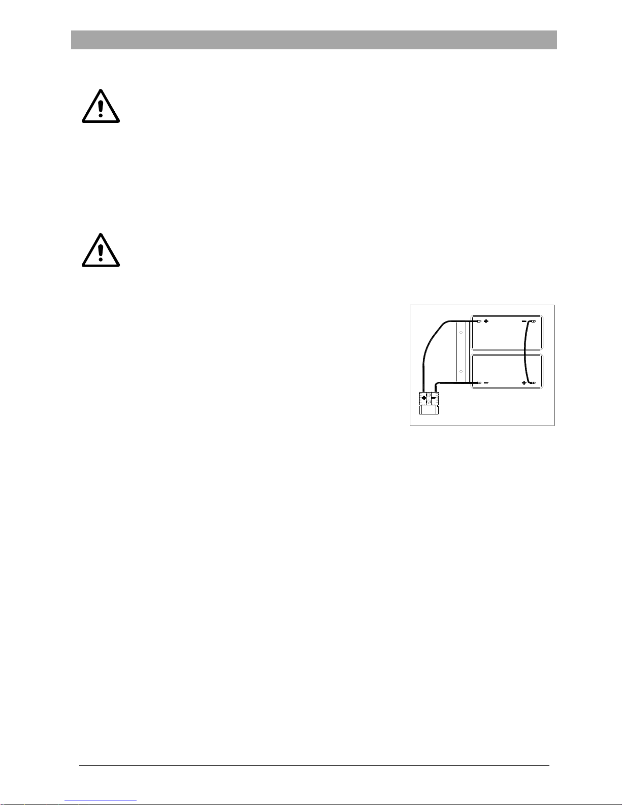
NOTE
The machine requires two 12V batteries, connecting according
to Figure 3.
The machine can be operated in one of following battery modes:
A) WET or GEL/AGM batteries are already installed and ready to
be used
1. Check the batteries and connect the battery connector to the machine.
2. Insert the key switch (40) and turn to “on”. If the green light (48) turns on, batteries are full charged for use; If the
yellow or red light (47 or 48) turns it on, the batteries must be charged.
B) Without Batteries
1. If your machine isn’t equipped with batteries, buy appropriate batteries *See the Technical Data Paragraph+. For
battery choice and installation, turn to qualified battery Retailers.
2. When batteries are ready, set the machine and the battery charger according to the type of installed batteries,
then follow the procedures shown in the next paragraph.
BATTERY INSTALLATION AND BATTERY TYPE SETTING (WET OR GEL/ AGM)
Set the electronic circuit board of the machine and battery charger according to battery types (WET or GEL/AGM)
following steps below:
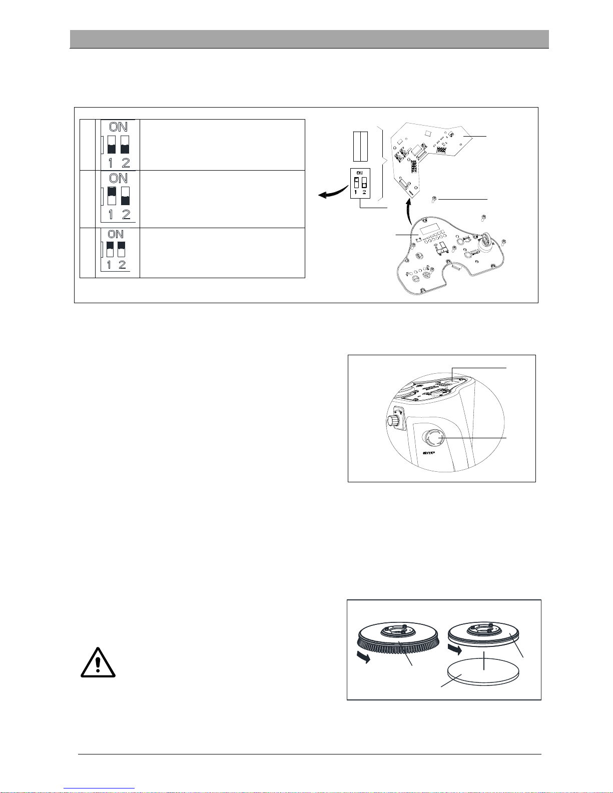
NOTE
When install new batteries, follow Figure 4 to set DIP switch, or batteries may be damaged by wrong
setting.
Machine setting
1. Insert key switch (40) and turn to “ON”, pay attention to below during the first seconds of machine start:
If the green light (37) flash, machine is set up to use GEL/AGM batteries.
If the yellow light (33) flash, machine is set up to use Discover EV AGM batteries.
If the red light (32) flash, machine is set up to use WET batteries.
2. Follow below steps to change the machine settings.
3. The factory setting of the machine is to use Discover EV AGM batteries. If the setting corresponds to selected
batteries, go to step 6 directly, or follow the next step.
Page 13
USER MANUAL ENGLISH
10
A
B
Figure 5
A
C
B
Figure 6
4. Unscrew the screw (B, Figure 4) on control panel, then turn over the PCBA (A) on the panel to find DIP switch (D),
follow Figure 4 for DIP settings.
5. Perform steps in reserve order of disassembly to fix control panel and lock the screw after setting is done.
1
WET BATTERIES
(NOTE: Turn pin1 and pin2 of DIP switch
to “OFF”)
2
DISCOVER EV AGM BATTERIES
(NOTE: Turn pin 1 of DIP switch to “ON”,
pin2 to “OFF”)
3
GENERAL GEL/AFM BATTERIES
(NOTE: Turn pin1 and pin2 of DIP switch
to “ON”)
Battery Installation
6. Open the recovery tank cover (4) and check the recovery tank (3) is empty, otherwise, empty it with the drain hose
(15).
7. Close the recovery tank cover (4).
8. Overturn the recovery tank (3) carefully.
9. The machine is supplied with cables suitable to install 2X12V
batteries. Carefully put the batteries into the compartment,
then install them correctly.
10. Route and install the battery cable as shown in (Figure 3),
then carefully tighten the nut on each battery terminal.
11. Place the protection cap on each terminal, then connect the
battery connector.
12. Carefully lower the recovery tank (3).
Charging the Batteries
13. Charging the batteries. [Refer to MAINTENANCE chapters].
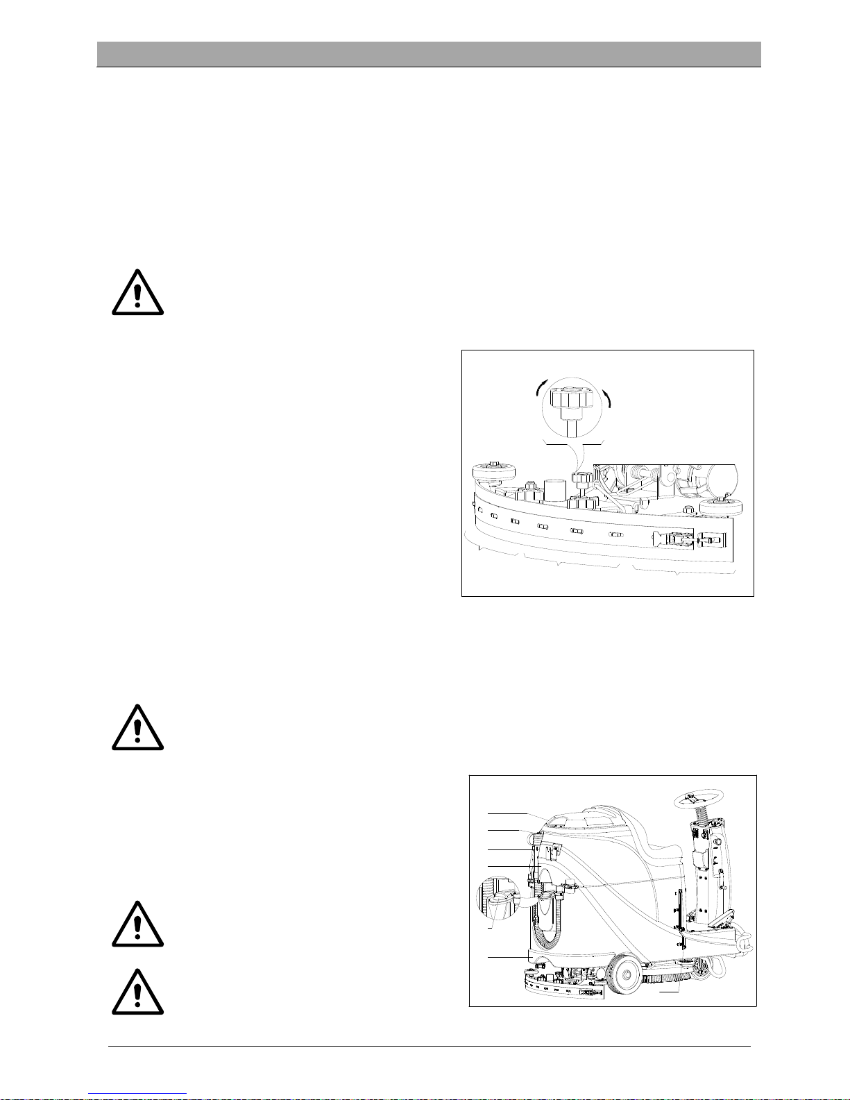
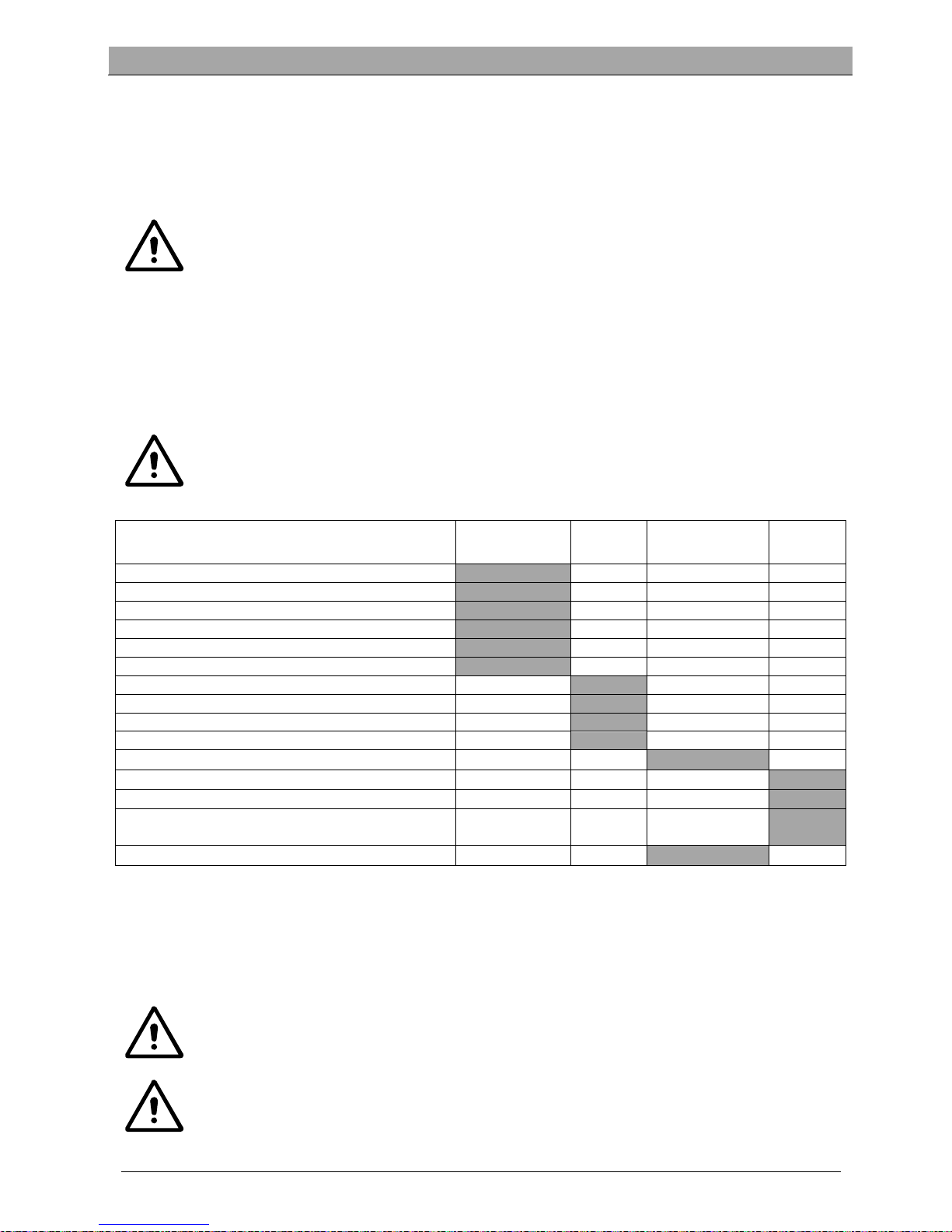
EMERGENCY BRAKING
If there is any emergency during machine operating, press the emergency switch (A, Figure 5), then all functions of
machine will stop, there is no display on control panel (B, Figure 5)
BRUSH/PAD INSTALLATION AND UNINSTALLATION
NOTE
Install suitable brush (A, Figure 6) or Pad (B and
C, Figure 6) according to the type of floor to be
cleaned.
CAUTION
Before installation or uninstallation of brush or
pad, make sure all the switches on machine are
in off position and lifting up the squeegee from
the floor. The operator must be equipped with
suitable personnel protection devices such as
gloves to reduce the risk of accidents. Proceed as
following:
OTHE
R
GEL/A
GM
DIS-EV
WET
D
A
B
C
Figure 4
Page 14
USER MANUAL ENGLISH
11
E
F
C
B
D
A
Figure 7
1. Insert key switch (40) and turn to “ON”.
2. Press the pedal (6) forward by foot to lift brush assembly (11) from the floor.
3. Rotate speed adjusting knob (42) in counterclockwise until to the end.
4. Place the brush (A, Figure 5) or pad (B, Figure 5) center align with brush deck.
5. Press the pedal (6) backward by foot to lower down brush assembly (11). Sit on the seat, press the brush button (39)
and depress the pedal (23) slightly, the brush/pad can be assembled automatically. Repeat these steps until
brush/pad is installed.
6. If step5 install the brush/pad but not successfully, please manually take the brush/pad down.
7. Depress the pedal (6) forward by foot to lift the brush assembly (11) from floor, press brush remove button (41) to
uninstall it automatically.
CAUTION!
Rotate the speed adjusting knob (42) to the minimum speed before depressing accelerate pedal (6) to
avoid the machine running too quickly when it is started. Make sure the brush/pad is installed correctly
before machine operating.
ADJUSTING THE BALANCE OF SQUEEGEE
1. Install the squeegee (13) and fasten the squeegee knob
(20), then connect the vacuum hose (19) to the squeegee.
2. Adjust the squeegee by squeegee adjusting handle (A,
Figure 7).
a) If there is gap between the ground and middle section
of rear squeegee blade (B), adjust the knob (A) in
counterclockwise direction (F) until all section of rear
squeegee blade good contact with ground, the front
blade touch the ground slightly.
b) If there is gap between the ground and both end
section of rear blade(C and D), adjust the knob (A) in
clockwise direction (E) until all section of rear blade
good contact with the ground, the front blade touch
the ground slightly.
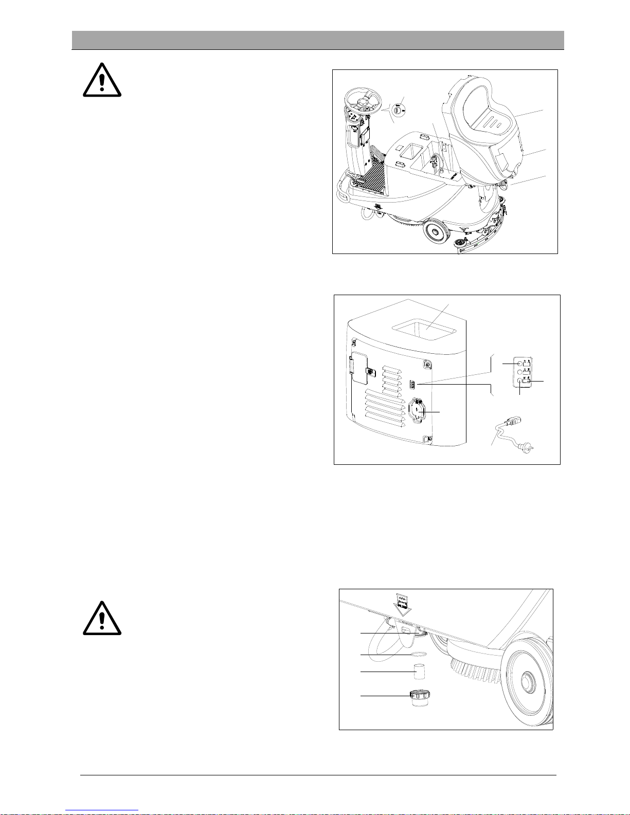
SOLUTION TANK FILLING
1. Open the water inlet cover (E, Figure 8).
2. Filling water or solution suitable for work performance through the water inlet with filter. The solution
temperature must not exceed +104F (+40°C).
3. Don’t overfill the tank, refer to water level indicator (G) for the water volume.
WARNING!
Use only low-foam and non-flammable detergents intended for automatic scrubber applications.
Drive motor inspection
1. Turn the key switch (A, Figure 9) to “ON”
2. Depress the accelerate pedal (C) slightly then loosen it to
check if the machine can be steered forward and stopped.
3. To ensure the security, confirm if the machine can be
stopped immediately by pressing the emergency button (B).
Rotate the emergency button to reset it.
CAUTION
Climbing capacity of the machine must not
exceed 10%.
CAUTION
The brake of drive motor is unstuck when the
motor works normally, it locks when the motor
stops working.
F
E
D
C
B
A
G
Figure 8
Page 15
USER MANUAL ENGLISH
12
B
C
D
A
Figure 9
A
C
E
D
B
F
G
H
I
L
M
N
O
P
Q
R
ST
U
Figure 10
Brake unstuck -the brake handle(D, Figure 9) locates above
Brake locked –the brake handle locates lower
In some special cases, such as machine packing/unpacking,
machine fault etc., need to move the machine without drive
motor working, please manually set the brake to unstuck
status to move it.
To avoid any security risk, ensure to set the brake back to
locked status after machine movement.
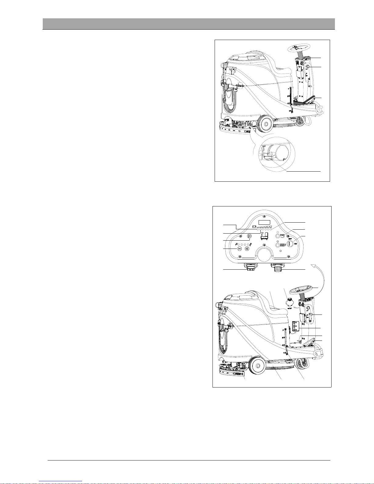
MACHINE START AND STOP
Starting the machine
1. Prepare the machine as shown in previous paragraph.
2. Sit on the seat (L, Figure 10), insert the key switch (A) and turn
it to “ON”. If the green light (C) is on, the batteries are fully
charged for use. If the yellow light (E) or red light (D) is on,
batteries must be charged before operation. [Refer to
MENTAINENCE chapters for batteries charging]
3. Lower the squeegee assembly to the floor.
NOTE
Make sure the squeegee assembly is lifted before
the machine steer backward, or the Machine will
be stopped and LED screen show “Error”
information.
4. Lower the brush assembly to the floor.
NOTE
Make sure to turn off brush button before brush
assembly is lifted, and lift the brush assembly
before machine steers forward/backward.
5. Press brush button (B)
6. Depress the accelerate pedal (R), operate the machine
forward or backward by steering wheel (N) together with
forward-backward switch (H), you can adjust speed by speed
adjusting knob (I).
7. Adjust solution flow by solution adjusting button (G) base on
cleaning requirement.
8. You can charge your phone or pad through USB charging
port (M) when the key switch (A) is turned to “ON”.
9. Press the horn button (F) to warn people when necessary.
10. If necessary, press the emergency button for machine
emergency stop.
NOTE
The brush motor, vacuum motor, drive motor and
control circuit are protected by overload protector (P).When the overload protector trip, do not
reset it immediately without finding out the root
cause, and make sure the motor is cooling-off
before reset.
Stopping the machine
11. Loosen the accelerate pedal (R, Figure 10), the machine stops running.
12. Press brush button (B) to stop brush motor.
13. Lift brush assembly (T) by depressing the pedal (Q).
14. Lift squeegee assembly (U) by squeegee lifting/lowering lever (O), and a few seconds later the vacuum system will
be closed.
Page 16

USER MANUAL ENGLISH
13
A
D
B
C
Figure 12
15. Turn the key switch to “OFF”
16. Ensure the machine is stopped.
MACHINE OPERATION (SCRUBBING AND DRYING)
1. Start the machine according to procedures in previous paragraphs.
2. Start cleaning by following procedures in section of “Starting the machine”.
3. If necessary, stop the machine to adjust squeegee according to section “Adjusting the balance of squeegee”.
CAUTION!
To avoid any damage to the floor surface, turn off the brush/pad-holder when the machine stop in one
place.
NOTE
For correct scrubbing/drying of floors at the sides of walls, we suggest to go near the walls with right
side (Bumper wheel side) of the machine as shown in below Figure 11.
Battery charging during the work
When there is green light (A, Figure 12) on, the batteries have
enough power for the machine to work normally; when all the
green lights off, the yellow light (C, Figure 12) is on, the power
of batteries are too low, please charge the batteries; when the
red light (B, Figure 12) flashes, the batteries has run out, the
vacuum motor and brush motor will be turned off
automatically a few seconds delay, please drive the machine
for batteries charging immediately.
CAUTION!
To avoid damaging the batteries and
shortening their working life, do not use the
machine once the batteries are flat.
Figure 11
Page 17
USER MANUAL ENGLISH
14
A
B
C
D
E
F
G
H
Figure 13
A
B
Figure 14
A
D
C
B
Figure 15
TANK EMPTYING
An automatic float shut-off system (B, Figure 13) blocks the vacuum system when the recovery water tank (C) is full. The
vacuum system deactivation is signaled by a sudden increase in the vacuum system motor noise frequency, also the
floor has not dried.
CAUTION!
If the vacuum system turns off accidentally, (For
example, when the float is activated because of a
sudden machine movement), to resume the
operation: turnoff the vacuum system by pressing
the switch (D, Figure 12), then open the cover (A,
Figure 11) and check that the float inside the grid
(B) has gone down to the water level. Then close
the cover (A) and turn on the vacuum system by
pressing the switch (D, Figure 12).
When the recovery water tank (C, Figure 13) is full, empty it
according to the following procedure.
Recovery water tank emptying
1. Stop the machine.
2. Lift the brush/pad deck (H, Figure 12) by pressing the pedal (G).
3. Lift the squeegee with the lever (H).
4. Drive the machine to the appointed disposal area.
5. Empty the recovery tank with the drain hose (D). Then rinse the
tank with clean water.
CAUTION!
When draining the wastewater, the drain hose
must be folded (A, Figure 14) and put to a low
position (B, Figure 14) before opening the drain
hose cover. Do not make the outlet of the drain
hose upward to drain the water vertically in order
to avoid wastewater spilling onto the operator.
Solution/clean water tank emptying
6. Perform steps 1 to 4 in chapter “Recovery water tank emptying”.
7. Empty the solution tank through the outlet cover (A, Figure
15). And then, rinse the tank with clean water.
AFTER USING THE MACHINE
After working, before leaving the machine:
1. Remove the brushes/pad-holder.
2. Empty the tanks (B and C, Figure 15) as shown in previous
paragraph.
3. Perform the daily maintenance procedures (see the
Maintenance chapter).
4. Store the machine in a clean and dry place, with the
brushes / pad-holders and the squeegee lifted or removed.
MACHINE LONG INACTIVITY
If the machine is not going to be used for more than 30 days,
proceed as follows:
1. Perform the procedures shown in “AFTER USING THE
MACHINE” paragraph.
2. Disconnect the battery connector (D, Figure 15).
Page 18
USER MANUAL ENGLISH
15
USING FOR THE FIRST TIME
After nine hours using of the machine for the first time, please check if any damage or abnormal situation, check
whether the fasteners or fittings is loose.
MAINTENANCE
WARNING!
Maintenance procedures must be performed after the machine is turned off and the battery charger
cable is disconnected. In addition, carefully read the safety chapters in the manual.
All scheduled or extraordinary maintenance procedures must be performed by qualified personnel or an authorized
Service Center. This guide only describes the general and common maintenance procedures.
For other maintenance procedures that are in below maintenance schedule table, please refer to the Service Manual
that can be consulted at any Service Center.
SCHEDULED MAINTENANCE TABLE
CAUTION!
The procedure marked with (1) must be performed when the machine is used after 9 hours for the first
time.
The procedure marked with (2) must be done by Service Center that qualified by our company.
Procedure Daily, after
each use
Weekly semiannually Yearly
Battery charging
Squeegee cleaning
Brush/Pad-holder cleaning
Tank cleaning
Tank sealing strip inspection
Float ball filter cleaning
Squeegee blade check and replacement
Cleaning water filter cleaning
Suction filter cleaning
WET battery fluid level check
Screw and nut tightness inspection
(1)
Brush/Pad-holder carbon brush check or replacement
(2)
Suction motor carbon brush check or replacement
(2)
Drive system motor carbon brush check or
replacement (only for machine with traction)
(2)
Add lubricating oil for rotating parts
(1)
BATTERY CHARGING
NOTE
Please charge the batteries when the yellow LED (32) or red LED (33) is on, or at the end of each working
cycle.
CAUTION
Always keep the battery in a full charged state can extend its lifetime.
CAUTION
Please charge the battery as soon as possible if the battery level is low. Otherwise, the lifespan of
battery can be reduced. It is better to check the battery at least once a week.
Page 19
USER MANUAL ENGLISH
16
CAUTION!
To be especial careful when battery is
charging, because there may be leaked
acid in the process of charging.
Battery acid is corrosive, if it accidentally
comes into contact with the skin or eyes,
rinse immediately with plenty of clean
water and go to see a doctor.
The preparation steps to charge the
batteries
1. Open the recovery tank cover (B, Figure 16) to check if
the recovery tank (C) is empty, or empty the recovery
tank through the drain hose (A).
2. Drive the machine to designated charging area.
3. Turn the key switch to “OFF”.
4. This step only for WET batteries:
Clean the battery surface if necessary.
Check the battery electrolyte level of the
batteries (D), if necessary, open the cover to full
fill electrolyte, and then recover it.
Keep the cover opened during charging.
5. Select one of below charging mode base on the
selected charger type.
Use on-board charger for battery charging
6. Connect the battery charger cable (A, Figure 17) to the
electric mains (G), and then all machine functions
except charging are cut off automatically.
The normally on red LED (B) states that the machine is
in process of charging.
7. The batteries are fully charged when the green LED (C)
becomes on.
8. Disconnect battery charge cable from electric mains after charging is completed, and then store the battery charger
cable in the storage box (D).
NOTE
For further information about on-board charger (E, Figure 17), please refer to relevant manual from
service center.
BRUSH/PAD CLEANING
CAUTION!
It is recommended to wear gloves when
cleaning the brush/pad-holder, since it may
contain sharp fragments.
1. Take the brush/pad-holder off base on procedures in
previous sections.
2. Clean the brush/pad-holder using water and detergent.
3. Check the integrity and abrasion conditions of the bristle
on the brush, if necessary, replace the brush.
4. Check the abrasion condition of the polishing pad, if
necessary, replace it.
D
A
B
C
E
Figure 16
B
A
C
D
Figure 18
Figure 17
E
C
G
A
B
D
Page 20
USER MANUAL ENGLISH
17
B
C
A
Figure 20
SOLUTION FILTER CLEANING
1. Drive the machine to the flat ground.
2. Make sure the machine is off.
3. Empty the solution tank (optional step).
4. Take down the solution filter cover (A, Figure 18) to
clean the filter screen (B), and them fix them back to the
filter support (D).
NOTE
The filter screen (B) must be correctly
positioned to the housing of filter support
(D).
SQUEEGEE CLEANING
NOTE
The squeegee must be clean and its blades
must be in good conditions in order to get
good drying.
CAUTION
It is advisable to wear protective gloves
when cleaning the squeegee because there
may be sharp debris.
1. Drive the machine on a level floor.
2. Turn the key switch (A, Figure 19) to “OFF”.
3. Lower the squeegee (B) with the lever (C).
4. Loosen the knobs (D) and remove the squeegee.
5. Disconnect the vacuum hose (E) from the squeegee.
6. Clean the steel or aluminum squeegee, especially the
compartments (A, Figure 20) and the holes (B). Check
the integrity, cuts and tears of the front blade (B) and
rear blade (C), if necessary, replace them according to
procedures in the following paragraph.
7. Assemble the squeegee in the reverse order of
disassembly.
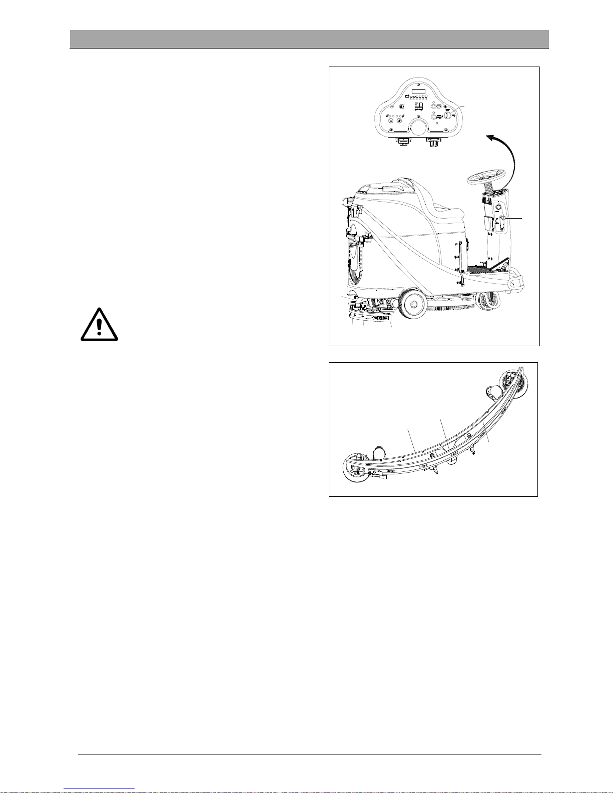
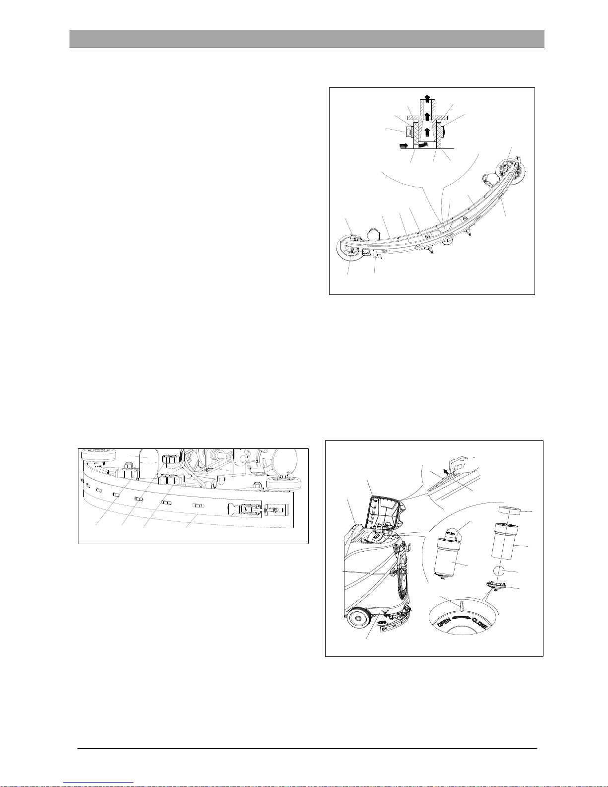
SQUEEGEE BLADE CHECK AND REPLACEMENT
1. Clean the steel or the aluminum squeegee, as shown in the previous paragraph.
2. Check that the edges (E, Figure 21) of the front blade (C) and the edges (F) of the rear blade (D) lay down on the
same level, along their length; if necessary adjust their height according to the following procedure:
Remove the tie rod (G), disengage the fasteners (M) and adjust the rear blade (D), then engage the fasteners (M)
and install the tie rod (G).
Loosen the knobs (I) and adjust the front blade (C), then tighten the knobs.
3. Check the front blade (C) and rear blade (D) for wear, cuts and tears; if necessary replace them according to the
following procedure. Check that the front corner (J) of the rear blade (D) is not worn; if necessary overturn the
blade to replace the worn corner with an integral one. If the other corners are worn too, replace the blade
according to the following procedure:
Remove the tie rod (G), disengage the fastener (M) and remove the retaining strip (K), then replace/overturn the
rear blade (D). Assemble the blade in the reverse order of disassembly.
Unscrew the knobs (I) and remove the retaining strip (L), then replace front blade (C). Assemble the blade in the
reserve order of disassembly. After the blade replacement (or overturning), adjust the height as shown in the
previous step.
4. Connect the vacuum hose (A, Figure 22) to the squeegee.
5. Install the squeegee (B) and screw down the knobs (C).
6. If necessary, adjust the squeegee balance adjusting knob (D).
A
B
C
D
E
D
Figure 19
Page 21
USER MANUAL ENGLISH
18
TANK AND VACUUM GRID WITH FLOAT CLEANING, AND COVER GASKET CHECK
1. Drive the machine on a level floor.
2. Ensure that the machine is off and the ignition key (40)
has been removed.
3. Turn the recovery tank lid (A, Figure 23) 90 degree
position where it can be took off from the tank, and then
take down the float ball filter (P) from the tank.
4. Clean the recovery tank lid (A), recovery tank (B), clean
water tank (C) and the float ball filter support frame (E).
Empty the recovery tank with the drain hose (15).
5. If necessary, follow the symbols “OPEN” and “CLOSE” as
shown in Figure 23 to open the bottom cover (F) of float
ball filter and then clean the float ball (D), filter support
frame (E) and filter sponge (I). After cleaning, fix the float
ball (D) into the filter support frame (E) and then align
the mark groove (L) of the bottom cap (F) of the float ball
filter with the mark groove (L) of the float filter support
frame (E). Screw the bottom cap of the float ball filter
tight, and fix the filter sponge (I) onto the float filter
support frame (E). Finally, connect it to the sewage
suction hose (M).
6. Inspect the integrity of the tank sealing strip.
NOTE
Tank sealing strip (G) makes to produce the vacuum inside the tank when suction motor works. The
tank must be sealed can effectively absorb the water from the ground to recovery tank.
7. Check whether the contact surface of sealing strip (G) is integrity and sealing is sufficient. If necessary, take the
sealing strip of the tank out of the groove (H) and replace it. Assembly the new sealing strip as shown in Figure 23,
the joint should be back in the middle area.
8. Close the recovery tank lid (A).
Figure 22
A
C
D
C
B
I
E
D
F
L
P
M
A
B
C
H
G
Figure 23
B
A
M
D
J
I
C
A
G
M
I
I
K
D
F
C
L
E
Figure 21
Page 22

USER MANUAL ENGLISH
19
A
B
C
D
E
F
G
Figure 24
FUSE CHECK/REPLACEMENT
1. Turn the key switch (D, Figure 24) to “OFF”.
2. Disconnect the battery connect cable.
3. Unscrew the screws (C) on the control panel and then turn over
the PCBA to find the fuse (A and B).
4. Check/replace the fuses:
A) F1 is the low-power circuit fuse (5A)
B) F3 is brush dismount fuse (20A)
5. After check/replacement is done, re-assemble in the reserve
order of dismount.
6. Check or reset the motor overload protector.
E) F5 is vacuum motor overload protector (30A)
F) F4 is drive motor overload protector (30A)
G) F2 is brush motor overload protector (30A)
ACCESSORIES/OPTIONS
In addition to the standard components, the machine can be equipped
with the following accessories/options, according to the machine
specific use.
For further information concerning the above mentioned optional
accessories, contact an authorized retailer.
Accessories/Options
See “Parts List” section
1. GEL/AGM batteries
2. Pads of different materials
TROUBLE SHOOTING
Trouble Probable causes Remedy
The motors do not work; no warning
light turns on (C9)
The battery connector is disconnected Connect the battery connector
The batteries are completely discharged Charge the batteries
The machine do not work, red battery
capacity warning light turns on (C8)
The batteries level is too low Charge the batteries
The machine do not go-forward /
backward
The control circuit board fault Replace the control circuit board
The drive motor controller fault
Refer to “DRIVE MOTOR ERROR
INDICATOR INFORMATION”
The operator not on the seat Sit on the seat
Squeegee is not lifted during machine
goes backward
Lift the squeegee
The brush motor does not work
The control circuit board fault Replace the control circuit board
Brush motor overload
Use soft bristle brush that is
suitable for cleaning, and reset the
brush motor overload protector
Brush motor contactor fault Contact after-sales service
Brush motor carbon brush wearing Contact after-sales service
Obstacles prevent the brush rotating Clean the brush
The drive motor does not work
Drive motor trouble light turns on
Refer to “DRIVE MOTOR ERROR
INDICATOR INFORMATION”
Drive motor overload
Reset drive motor overload
protector and check drive
motor/circuit
The vacuum motor does not work
Vacuum motor overload
Reset vacuum motor overload
protector and check vacuum motor
Relay of vacuum motor fault Contact after-sales service
Page 23

USER MANUAL ENGLISH
20
Control board fault Replace the control board
Insufficient suction, the floor cannot be
dried
Recovery tank is full Empty the recovery tank
Drain hose and squeegee poor
connection
Connect the drain hose and
squeegee correctly
Float ball filter block
Clean the float ball filter and check
the float ball position status
Squeegee is dirty or wearing Check and clean the squeegee
The recovery tank cover is not closed
properly, or the gasket is damaged, or
the Bend tube is clogged
Close the cover correctly, or re-
place the gasket or clean the Bend
tube.
The Recovery tank is dirty Clean the recovery tank
Insufficient solution supply to brush
plate
The solution filter is dirty Clean the filter
The solution tank empty indicator is on Fill the solution tank
The solution tank is too dirty Clean the solution tank
Squeegee leaves scratch on the floor
There are debris under the squeegee
blade
Remove the debris
Squeegee blade wear, crack, aged Replace the squeegee blades
The squeegee balance is not adjusted Adjust the squeegee balance
Drive motor brake failure The brake is locked Set the brake unstuck
DRIVE MOTOR ERROR INDICATOR INFORMATION
LED CODES FAULT POSSIBLE CAUSE
1.1
¤¤
THERMAL FAULT
1. Temperature >80°C or < -10°C.
2. Excessive load on vehicle.
3. Operation in extreme environments.
4. Electromagnetic brake not releasing.
1.2
¤¤¤
THROTTLE FAULT
1. Throttle input wire open or shorted.
2. Throttle pot defective.
3. Wrong throttle type selected.
1.3
¤¤¤¤
SPEED POT FAULT
1. Speed limit pot wire(s) broken or shorted.
2. Broken speed limit pot.
1.4
¤¤¤¤¤
UNDERVOLTAGE FAULT
1. Battery voltage <17 volts.
2. Bad connection at battery or controller.
1.5
¤¤¤¤¤¤
OVERVOLTAGE FAULT
1. Battery voltage >31 volts.
2. Vehicle operating with charger attached.
3. Intermittent battery connection.
2.1
¤¤¤
MAIN OFF FAULT
1. Main contactor driver failed open.
2.3
¤¤¤¤¤ MAIN FAULT ❊
1. Main contactor welded or stuck open.
2. Main contactor driver fault.
2.4
¤¤¤¤¤¤
MAIN ON FAULT
1. Main contactor driver failed closed.
3.1
¤¤¤¤ WIRING FAULT ❊
1. Misadjusted throttle.
2. Broken throttle pot or throttle mechanism.
3.2
¤¤¤¤¤
BRAKE ON FAULT
1. Electromagnetic brake driver shorted.
2. Electromagnetic brake coil open.
3.3
¤¤¤¤¤¤ PRECHARGE FAULT ❊
1. Brake driver shorted.
2. Precharge circuit damaged.
3. MOSFET failure.
3.4
¤¤¤¤¤¤¤
BRAKE OFF FAULT
1. Electromagnetic brake driver open.
2. Electromagnetic brake coil shorted.
3.5
¤¤¤¤¤¤¤¤
HPD FAULT
1. Improper sequence of throttle and KSI, push,
or inhibit inputs.
2. Misadjusted throttle pot.
4.1
¤¤¤¤¤ CURRENT SENSE FAULT ❊
1. Short in motor or in motor wiring.
2. Controller failure.
4.2
¤¤¤¤¤¤ HARDWARE FAILSAFE ❊
1. Motor voltage does not correspond to throttle
request.
2. Short in motor or in motor wiring.
3. Controller failure.
Page 24

USER MANUAL ENGLISH
21
4.3
¤¤¤¤¤¤¤ EEPROM CHECKSUM FAULT †
1. EEPROM failure or fault.
4.5
¤¤¤¤¤¤¤¤¤ BATTERY DISCONNECT FAULT ❊
1. Battery not connected.
2. Poor connection to battery terminals.
❊= Must cycle keys witch to clear.
† = Must use programmer to clear, as follows: select Program menu, alter data value of any parameter, cycle keys
witch.
NOTE
The machine which is equipped with on-board charger will not be operated when the on-board charger
malfunction, please contact our qualitied maintenance center for help.
SCRAPPING
Scrap the machine by the qualified waste treatment institution.
Before the machine is scrapped, please take away and segregate below subassembly that relevant laws and regulations
request must be disposed in appropriate way.
– Battery
– Brush/Pad-holder
– Plastic hose and plastic parts
– Electrical and electronic components (*)
(*) Please contact our service center to destroy any of electrical and electronic components.
Page 25

MANUEL UTILISATEUR FRANÇAIS
TABLE DES MATIÈRES
INTRODUCTION .......................................................................................................................... 22
CONTENU DU MANUEL ET BUT ........................................................................................................................................... 22
COMMENT GARDER CE MANUEL ........................................................................................................................................ 22
DÉCLARATION DE CONFORMITÉ .......................................................................................................................................... 22
ACCESSOIRES ET ENTRETIEN ................................................................................................................................................ 22
CHANGEMENT ET AMÉLIORATION ...................................................................................................................................... 22
CHAMP D'APPLICATION ....................................................................................................................................................... 22
DONNÉES D'IDENTIFICATION DE LA MACHINE .................................................................................................................... 22
TRANSPORT ET DÉBALLAGE ................................................................................................................................................. 22
SÉCURITÉ ................................................................................................................................... 23
SYMBOLES QUI APPARAISSENT SUR LE MANUEL D'UTILISATION ........................................................................................ 23
CONSIGNES GÉNÉRALES DE SÉCURITÉ ................................................................................................................................. 23
DESCRIPTION DE LA MACHINE .................................................................................................... 25
STRUCTURE DE LA MACHINE ............................................................................................................................................... 25
PANNEAU DE COMMANDE .................................................................................................................................................. 26
INFORMATIONS D'AFFICHAGE ÉCRAN LED .......................................................................................................................... 26
FENÊTRE D'AFFICHAGE DU VOYANT DU CHARGEUR ........................................................................................................... 26
PARAMÈTRES TECHNIQUES ................................................................................................................................................. 27
SCHÉMA DU CIRCUIT ........................................................................................................................................................... 28
GUIDE D'UTILISATION ................................................................................................................. 30
INSTALLATION ET CONFIGURATION D'UNE NOUVELLE BATTERIE ....................................................................................... 30
INSTALLATION DES BATTERIES ET RÉGLAGE DU TYPE DE BATTERIE (AVEC ENTRETIEN OU GEL/AGM) .............................. 30
FREINAGE D'URGENCE ......................................................................................................................................................... 31
INSTALLATION ET DÉSINSTALLATION DE LA BROSSE / DU COUSSINET ............................................................................... 31
AJUSTEMENT DE L’ÉQUILIBRE DE L' EMBOUCHURE ............................................................................................................ 32
REMPLISSAGE DU RÉSERVOIR DE LA SOLUTION .................................................................................................................. 32
DÉMARRAGE ET ARRÊT DE LA MACHINE ............................................................................................................................. 33
FONCTIONNEMENT DE LA MACHINE (BROSSAGE ET SÉCHAGE) ......................................................................................... 34
VIDANGE DU RÉSERVOIR ..................................................................................................................................................... 35
APRÈS UTILISATION DE LA MACHINE ................................................................................................................................... 35
LONGUE INACTIVITÉ DE LA MACHINE ................................................................................................................................. 35
UTILISATION POUR LA PREMIÈRE FOIS ................................................................................................................................ 36
ENTRETIEN ................................................................................................................................. 36
CALENDRIER D'ENTRETIEN PROGRAMME ........................................................................................................................... 36
CHARGEMENT DE BATTERIE ................................................................................................................................................ 36
NETTOYAGE DE LA BROSSE/DU DISQUE .............................................................................................................................. 37
NETTOYAGE DU FILTRE DE SOLUTION ................................................................................................................................. 38
NETTOYAGE DE L‘EMBOUCHURE ......................................................................................................................................... 38
VÉRIFICATION ET REMPLACEMENT DE LA LAMELLE DE L’EMBOUCHURE ........................................................................... 38
NETTOYAGE DU RÉSERVOIR ET DE LA GRILLE D'ASPIRATION AVEC LE FLOTTEUR, VÉRIFICATION DU JOINT DE COUVERCLE ...... 39
VÉRIFICATION / REMPLACEMENT DU FUSIBLE .................................................................................................................... 40
ACCESSOIRES/OPTIONS ....................................................................................................................................................... 40
DÉPANNAGE .............................................................................................................................. 40
RECYCLAGE ................................................................................................................................ 42
Page 26

MANUEL UTILISATEUR FRANÇAIS
22
INTRODUCTION
REMARQUE
Les chiffres entre parenthèses renvoient aux éléments présentés dans le chapitre Description de la
Machine.
CONTENU DU MANUEL ET BUT
Le but de ce Mode d'Emploi est de fournir à l'opérateur des informations nécessaires afin d'utiliser correctement la
machine et en toute sécurité. Il contient des informations sur des données techniques, la sécurité, l'exploitation, le
stockage, la maintenance, les pièces de rechange et comment mettre au rebut.
Avant d'effectuer toute opération sur la machine, peu importe les opérateurs et les techniciens qualifiés doivent lire
attentivement ce manuel. Contacter le centre d'entretien de notre société pour toute question concernant ce manuel
ou pour toute information complémentaire qui est nécessaire.
Les opérateurs ne doivent pas effectuer de procédures qui devraient être faites par des techniciens qualifiés. Notre
société ne sera pas responsable des dommages provenant du non-respect de cette interdiction.
COMMENT GARDER CE MANUEL
Le manuel doit être conservé près de la machine, dans une enveloppe spéciale, loin de liquides et d'autres substances
qui peuvent causer des dommages à celle-ci.
DÉCLARATION DE CONFORMITÉ
La déclaration de conformité est fournie avec la machine et en atteste la conformité aux lois en vigueur.
REMARQUE
Les copies de la déclaration originale de conformité sont fournies avec la documentation de la machine.
ACCESSOIRES ET ENTRETIEN
Toutes les opérations d'entretien et de réparation doivent être effectuées par un personnel qualifié ou par un service de
maintenance agréé. SEULS les pièces détachées et les accessoires autorisés doivent être utilisés.
Contacter notre service après-vente pour tout service ou achat d'accessoires ou pièces détachées si nécessaire.
CHANGEMENT ET AMÉLIORATION
Nous nous sommes engagés à une amélioration continue de nos produits. Notre, société se réserve le droit de modifier
et d'améliorer la machine sans vous en informer.
CHAMP D'APPLICATION
L'autolaveuse est à usage commercial et industriel. Elle est adaptée pour le nettoyage de sols lisses et durs. Pour plus de
sécurité, elle doit être utilisée par un personnel qualifié. Elle ne convient pas pour une utilisation en extérieur ou pour le
nettoyage de la moquette ou des sols rugueux.
DONNÉES D'IDENTIFICATION DE LA MACHINE
Le numéro de série et le nom du modèle de la machine sont indiqués sur l'étiquette.
Ces informations sont importantes. Utiliser le tableau suivant pour noter les données d'identification de la machine,
nécessaires lors de la commande de pièces de rechange.
MODÈLE DE LA MACHINE.........................................................................
NUMÉRO DE SÉRIE DE LA MACHINE.........................................................
TRANSPORT ET DÉBALLAGE
À la livraison s'assurer que l'emballage et la machine sont intacts et en bon état. En cas de dommage, porter à la
connaissance du transporteur les dommages et avant d'accepter les marchandises, effectuer des réserves.
Suivre attentivement les instructions sur l'emballage, lors du déballage de la machine.
Page 27

MANUEL UTILISATEUR FRANÇAIS
23
Vérifier l'emballage pour assurer que les éléments suivants sont inclus:
1. Documentations techniques, y compris manuel utilisateur et manuel du chargeur à bord s'il est équipé du chargeur
à bord.
2. Câble du chargeur, s'il est équipé du chargeur à bord.
SÉCURITÉ
Les symboles suivants indiquent les situations potentiellement dangereuses. Toujours lire attentivement ces
informations et prendre toutes les précautions nécessaires pour protéger les personnes et les biens.
SYMBOLES QUI APPARAISSENT SUR LE MANUEL D'UTILISATION
DANGER!
Cela indique une situation dangereuse avec risque de mort pour l'opérateur.
ATTENTION!
Cela indique un risque potentiel de blessure pour les personnes.
ATTENTION!
Cela indique un avertissement ou une remarque concernant des fonctions clés ou utiles.
Prêter attention aux paragraphes marqués par ce symbole.
REMARQUE
Cela indique une remarque sur des fonctions clés ou utiles.
CONSULTATION
Cela indique la nécessité de se référer aux instructions d'utilisation avant toute manipulation.
CONSIGNES GÉNÉRALES DE SÉCURITÉ
Les avertissements et les mises en garde spécifiques, pour informer des dommages potentiels aux personnes et à la
machine, sont indiqués ci-dessous.
DANGER!
Cette machine doit être utilisée par un personnel qualifié selon les conseils du manuel.
Avant d'effectuer toute opération de nettoyage, d'entretien, de réparation ou de remplacement, lire
attentivement toutes les instructions, s'assurer d'éteindre la machine et de débrancher le connecteur de la
batterie.
Ne pas faire fonctionner la machine à proximité de poudres, liquides ou vapeurs toxiques, dangereux,
inflammables et/ou explosifs. Cette machine ne convient pas pour la collecte des poudres dangereuses.
Ne pas porter de bijoux, lorsque vous travaillez à proximité de composants électriques.
Ne pas travailler sous la machine soulevée, sans la maintenir avec des sangles de sécurité.
Lors de l'utilisation de batteries au plomb (AVEC ENTRETIEN), elles peuvent émettre des gaz inflammables en
utilisation normale, vous devez éloigner les étincelles, les flammes, les substances fumigènes et les éléments
rayonnants, éclairants et brûlants des batteries.
Quand vous chargez les batteries au plomb (AVEC ENTRETIEN), elles peuvent émettre de l'hydrogène gazeux
ce qui peut provoquer des explosions. Assurez-vous que le local de charge soit bien aéré et éloigné des
flammes nues.
ATTENTION!
Page 28

MANUEL UTILISATEUR FRANÇAIS
24
Inspecter attentivement la machine avant chaque utilisation. Veiller à ce que tous les composants aient été
bien assemblés avant l'utilisation. À défaut cela peut causer des dommages aux personnes et aux biens.
Avant d'utiliser le chargeur de batterie, veiller à ce que les valeurs de fréquence et de tension indiquées sur
l'étiquette du numéro de série de la machine correspondent à celles du secteur.
Ne jamais déplacer la machine en tirant sur le câble du chargeur de batterie. Ne pas faire passer le câble sous
une porte fermée. Ne pas faire fonctionner la machine avec le câble du chargeur de batterie. Éloigner le
câble du chargeur de batterie des surfaces chauffées.
Ne pas charger les batteries si le câble de chargeur de batterie ou la fiche sont endommagés.
Pour réduire le risque d'incendie, de choc électrique ou de blessure, s'assurer que la machine est éteinte
avant de partir.
Utiliser ou stocker la machine en intérieur dans des conditions sèches, il est interdit de l'utiliser en extérieur.
La température de stockage et celle de travail doivent être comprise entre 0 ° C et +40 ° C, l'humidité de l'air
doit être comprise entre 30% et 95%.
Ne pas utiliser la machine sur des pentes avec une inclinaison dépassant ce qui est défini dans le cahier des
charges.
Lors de l'utilisation et de la manipulation de détergents de nettoyage de sols, suivre les instructions sur les
étiquettes des bouteilles de détergent et porter des gants et des protections appropriées.
Utiliser des brosses et des disques fournis avec la machine ou définis dans le manuel. L'utilisation d'autres
brosses ou de disques pourrait nuire à la sécurité.
En cas de dysfonctionnements de la machine, vérifier l'entretien de la machine. Si nécessaire, demander
l'assistance du personnel autorisé ou d'un centre de maintenance agréé.
Prendre toutes les précautions nécessaires pour empêcher les cheveux, les bijoux et les vêtements amples
d'être retenus par des pièces en mouvement de la machine.
Ne pas utiliser la machine dans des endroits particulièrement poussiéreux.
Ne pas laver la machine avec des jets d'eau directs ou sous pression, ou avec des substances corrosives.
Ne pas heurter des étagères ou des échafaudages, en particulier là où un risque de chute d'objets existe.
Ne pas incliner de récipients de liquide sur la machine, utiliser le porte gobelet.
Pour éviter d'endommager le sol, ne pas laisser la brosse/le disque fonctionner alors que la machine est à
l'arrêt.
En cas d'incendie, utiliser un extincteur à poudre. Ne pas utiliser les extincteurs liquides.
Ne pas enlever ou modifier les autocollants de la machine.
Suivre scrupuleusement les instructions d'entretien journalier.
Faire attention lors du transport de la machine, lorsque la température est basse. L'eau, dans le réservoir de
récupération et dans les tuyaux, pourrait geler et causer de sérieux dommages à la machine.
Si les pièces détachées doivent être remplacées, commander les pièces détachées D'ORIGINE auprès de
détaillants agréés.
Retourner la machine au centre d'entretien, si elle ne fonctionne pas comme d'habitude ou si elle est
endommagée.
Pour assurer un fonctionnement adéquat et sécurisé de la machine, l'entretien prévu indiqué dans le
chapitre de ce manuel, doit être effectué par le personnel autorisé ou un centre d'entretien autorisé.
La machine doit être correctement recyclée, en raison de la présence de matières toxiques (batteries, etc.),
qui sont soumises à des normes qui exigent l'élimination dans des centres spéciaux (voir le chapitre
Recyclage).
Cette machine est un outil de nettoyage, et ne doit pas être utilisée pour toute autre d'utilisation.
Toujours garder les ouvertures exemptes de poussière, de poils et de tout autre corps étranger qui pourrait
réduire le flux d'air. Ne pas utiliser la machine si les ouvertures sont bouchées.
Utiliser uniquement la machine lorsqu'un éclairage adéquat est fourni.
Cette machine n'est pas conçue pour être utilisée par des personnes physiquement ou intellectuellement
déficientes ou sans expérience ni connaissances, à moins qu'elles ne soient sous surveillance ou bien qu'elles
n’aient été informées quant à l'utilisation de l'appareil de manière sécurisée, par une personne responsable
de leur sécurité.
Une attention particulière est nécessaire lorsqu'elle est utilisée à proximité des enfants.
Les enfants doivent rester sous surveillance afin de s'assurer qu'ils ne jouent pas avec la machine.
Tout en utilisant cette machine, prendre soin de ne pas causer de dommages aux personnes ou aux objets se
trouvant aux alentours.
Page 29

MANUEL UTILISATEUR FRANÇAIS
25
DESCRIPTION DE LA MACHINE
STRUCTURE DE LA MACHINE (comme représenté sur la Figure 1)
1. Volant
2. Siège
3. Réservoir de récupération
4. Couvercle du réservoir de récupération
5. Port USB de charge
6. Pédale
7. Roue avant
8. Protection gauche
9. Filtre de solution
10. Brosse
11. Carter de brosse
12. Roue arrière
13. Ensemble de raclette
14. Bouchon de vidange de solution
15. Tuyau de vidange des égouts
16. Bouchon pour remplissage
17. Réservoir de solution
18. Molette de réglage de la raclette
19. Embout d’aspiration
20. Visserie pour la raclette
21. Panneau de contrôle
22. Interrupteur d'urgence
23. Levier de levage / de descente de la raclette
24. Pédale d'accélération
25. Parechoc avant
26. Indicateur de niveau de solution
27. Protection droite
28. Batterie
29. Moteur d'entraînement
30. Support du bloc de frein
31. Attache rapide de la lame de raclette
1
2 3 4
5
6
7
8
9 10 11 12
13 14
15
16
17
18
19
21
22
23
24
25
26
27
28
29
30
31
20
Figure 1
Page 30

MANUEL UTILISATEUR FRANÇAIS
26
DESCRIPTION DE LA MACHINE
PANNEAU DE COMMANDE (comme représenté sur la Figure 2)
31. Écran LED
32. Voyant d'avertissement de batterie déchargée
(rouge)
33. Voyant de batterie semi-déchargée (jaune)
34. Bouton du klaxon
35. Bouton de réglage du volume de solution
36. Interrupteur avant-arrière
37. Voyant de batterie complètement chargée (vert)
38. Voyant de réservoir de solution vide
39. Bouton de la brosse
40. Clé de contact
41. Bouton de désinstallation de brosse
42. Voyant d‘indication problème de traction
43. Bouton de réglage de la vitesse
44. Protecteur contre la surcharge du moteur d'aspiration
45. Protecteur contre la surcharge du moteur
d'entraînement
46. Protecteur contre la surcharge du moteur de la brosse
47. Voyant de charge de la batterie (rouge)
48. Voyant de batterie semi-chargée (jaune)
49. Voyant de batterie complètement chargée (vert)
50. Couvercle de la fiche du chargeur
51. Fiche du chargeur
INFORMATIONS D'AFFICHAGE ÉCRAN LED
STOP– La machine ne peut pas se déplacer, la brosse cesse de fonctionner mais le moteur d'aspiration peut fonctionner
(00012.3) – Le nombre total d'heures de fonctionnement de la machine est de 12,3 heures
L0-(18) – Tension de la batterie inférieure à 18V
U-(25.5) – Tension de la batterie est 25,5V
ERR-01 – - La raclette n'est pas soulevée lorsque la machine recule.
FENÊTRE D'AFFICHAGE DU VOYANT DU CHARGEUR (comme représenté sur la Figure 2)
1. Au début de la charge, le voyant LED jaune (48) scintille, le voyant LED rouge (47) et le voyant LED vert (49)
s'allument pour une seconde, le voyant LED rouge s'éteint et puis le voyant LED vert scintille quelques fois avant
que le voyant LED rouge sur le chargeur est normal. C'est la première étape de charge.
2. Après la charge pendant un certain temps, le voyant LED rouge (47) sur le chargeur s'éteint, le voyant LED jaune (48)
s'allume, c'est la deuxième étape de charge.
3. Lorsque la charge est complète, le voyant LED jaune (48) s'éteint, le voyant LED vert (49) s'allume pour indiquer que
la batterie est complètement chargée.
REMARQUE
Dans le processus de charge, si le voyant jaune (48) est allumé, il peut être causé par : la batterie et le
chargeur ne correspondent pas, la batterie est mal connectée ou la sortie est court-circuitée.
Le clignotement du voyant rouge du chargeur peut être causé par le court-circuit interne du chargeur.
42
31
32
35
36
38
39
40
41
43
37
33
44
45
47
48
34
50
46
49
51
Figure 2
Page 31

25
MANUEL UTILISATEUR FRANÇAIS
27
PARAMÈTRES TECHNIQUES
MODÈLE AS530R
Dimensions de l'emballage (L x l x H) mm 1470*730*1310
Hauteur de la machine mm 1120
Longueur de la machine mm 1360
Largeur de la machine (sans raclette) mm 580
Poids de la machine avec réservoirs vides
(sans batteries)
Kg 140
Poids total en charge (GVW) Kg 270
Poids machine emballée Kg 245
Capacité de réservoir de la solution Litre 72
Capacité de réservoir de récupération Litre 73
Puissance du moteur d'aspiration Watt 400
Colonne d'aspiration mm H₂O 1223
Pente admissible (Max) % 10
Diamètre roues avant mm φ175
Diamètre roue arrière mm φ230
Niveau sonore dB(A) 69
Débit d’eau L/min 0,84-2,0
Largeur de travail mm 530
Largeur de l’embouchure mm 730
Diamètre de la brosse/du disque mm 530
Puissance du moteur de brosse Watt 450
Vitesse de la brosse Tr/min 160
Pression de la brosse/du disque (Max) Kg
Puissance du moteur d'entraînement Watt 300W
Vitesse de travail Km/h 5,5km/h
Tension V 24V
Batterie Ah 2x100AH (20 heures)
Chargeur de batterie V/A 24V 10A
Dimensions de l'emballage (L x l x H) mm 350*380*300
Spécification du chargeur USB V/A 5V, 0,8A
Page 32

MANUEL UTILISATEUR FRANÇAIS
28
SCHÉMA DU CIRCUIT
C
U
RTIS 1212
M1
M1
B+
B-
2
4
3
1
J1
J2
SPK
BU2
BN2
6
2
7
384
9
5
10
1
EB1
5
1
6
2
7
3
8
4
1
2
J3
SW
1
AC
DC
+
_
NC
F
2
30A
R
L1
R
L2
YV
R
L3
SQ
+
_
7
6
5
4
3
2
1
14
13
12
11
10
2
1
8
9
M
EB2
VR
KA
J4
J5
M
M
F3
30A
F4
30A
BAT
24V
F1
5
A
F5 20A
W
H
1
WH1
WH1
RD2
RD2
RD2
RD3
RD1
BK1 BK3 BK2 BK3
RD4
RD/BK
RD/BK
RD/BK
RD3
RD4
BK5
BK5
YEYE YERD4
BN/BK
BU/BK
BN2
BK5
BK5
BK
5
OR
W
H2
BN1
BN1
BN1
YE
WH2
GN/BK
OR
SW7
RD4
SW6-A
YE
YE
PU
BK5
BK4
BU/BK
RD4
BN2
OR
GN
PU
GY
BN
1
BK4
SW2
M2
M1
M3
BK5
BK5
SW
3
SW
4
SW
6-
B
RL3
RL2
RL1
OR
GY
CH
RD4
100K
3
SW
5
BU
1
RD4
EB3
BK5
RD4
BK5
1
+
PU
WI
R
E ROD
RD1
RD2
RD3
BK1
BK2
RED/6AWG
RED/10AWG
RED/18AWG
BLACK/6AWG
BLACK/10AWG
RD/BK RED/BLACK / 20AWG
BN1 BROWN/14AWG
BN2 BROWN/20AWG
BK4 BLACK/14AWG
BK5
BLAC
K/18
AWG
BK3
BLAC
K/12
AWG
SW2
SW3
SW1
M1
M2
M3
BR
USH MOTOR
VACUUM MOTOR
DRIVE MOTOR
CLEAN WATER LEVEL SWITCH
VACUUM MOTOR SWITCH
KEY SWITCH
COMPONENTS
VR SPEED POTENTIOMETER
F
OO
T THROTTLE
SQ
EMERGENCY-STOP SWITCH
SW4
SW5 OPT
ION
AL MODE SWITCH
OPTIONAL REVERSE SWITCH SW6-B
OPT
ION
AL REVERSE SWITCH SW6-A
SPK 12VDC BUZZER
KA BR
A
KE
SW7
SEAT
S
WITCH
BA
T
C
H
EB1
EB3
F1
F2
F3
RL1
RL2
24V BAT
T
ERIES
BATTERY CHARGER
CONTROL PANEL BOARD
BRUSH MOTOR CIRCUIT BREAKER
VACUUM MOTOR CIRCUIT BREAKER
BRUSH MOEOR ELECTROM SWITCH
DRIVE ELECTRONIC BOARD
VACUUM MOEOR ELECTROM SWITCH
DRIVE SYSTEM CIRCUIT BREAKER F4
YV WATER ELECTROVALVE
CONTROL PANEL BOARD FUSE
COMPONENTS
R
L
3
DRIVE SYSTEM ELECTROM SWITCH
EB2
U
SB CHARGING ELECTRONIC BOARD
BR
U
SH RELEASE FUSE
F5
WI
R
E ROD
GN GREEN/20AWG
GN/BK
GREEN/BLACK /20AWG
BN/BK BROWN/BLACK / 20AWG
BU/BK BLUE/BLACK / 20AWG
PU PURPLE/20AWG
OR ORANGE/20AWG
YE YELLOW/20AWG
WH1
WHITE/12AWG
WH
2
WHITE/20AWG
BU1 BLUE/18AWG
GY
GR
AY/20
AWG
R
D
4 RED/20AWG
BU2
BLUE/20AWG
Page 33

MANUEL UTILISATEUR FRANÇAIS
29
COMPOSANTS COMPOSANTS FIL MACHINE FIL MACHINE
BAT BATTERIES 24V M1 MOTEUR DE LA BROSSE RD1 ROUGE/6AWG BN/BK MARRON/NOIR/20AWG
CH CHARGEUR DE BATTERIE M2 MOTEUR D'ASPIRATION RD2 ROUGE/10AWG BU1 BLEU/18AWG
EB1 PANNEAU DE CONTRÔ LE M3 MOTEUR D'ENTRAÎNEMENT RD3 ROUGE/18AWG BU2 BLEU/20AWG
EB2
CARTE ELECTRONIQUE DU
CHARGEUR USB
SW1
INTERRUPTEUR D'ARRÊT
D'URGENCE
RD4 ROUGE/20AWG BU/BK BLEU/NOIR/20 AWG
EB3 CARTE ELECTRONIQUE DU MOTEUR SW2 CLÉ DE CONTACT RD/BK ROUGE/NOIR/20AWG GN VERT/20AWG
RL1
INTERRUPTEUR ELECTRONIQUE DU
MOTEUR DE LA BROSSE
SW3
INTERRUPTEUR DE NIVEAU
D'EAU PROPRE
BK1 NOIR/6AWG GN/BK VERT/NOIR/20AWG
RL2
INTERRUPTEUR ELECTRONIQUE DU
MOTEUR D'ASPIRATION
SW4
INTERRUPTEUR DU MOTEUR
D'ASPIRATION
BK2 NOIR/10AWG GY GRIS/20AWG
RL3
INTERRUPTEUR ELECTRONIQUE DU
SYSTÈME D'ENTRAÎNEMENT
SW5
INTERRUPTEUR OPTIONNEL
DE MODE
BK3 NOIR/12AWG PU VIOLET/20AWG
YV ÉLECTROVANNE D'EAU SW6-A
INTERRUPTEUR OPTIONNEL
D'ARRIÈRE
BK4 NOIR/14AWG OR ORANGE/20AWG
F1
FUSIBLE DU PANNEAU DE
CONTRÔ LE
SW6-B
INTERRUPTEUR OPTIONNEL
D'ARRIÈRE
BK5 NOIR/18AWG YE JAUNE/20AWG
F2
DISJONCTEUR DU MOTEUR DE LA
BROSSE
SW7 INTERRUPTEUR DU SIÈGE BN1 MARRON/14AWG WH1 BLANC/12 AWG
F3
DISJONCTEUR DU MOTEUR
D'ASPIRATION
SQ ACCÉLÉRATEUR A PÉDALE BN2 MARRON/20AWG WH2 BLANC/20AWG
F4
DISJONCTEUR DU SYSTÈME
D'ENTRAÎNEMENT
SPK AVERTISSEUR DE 12VDC
F5 FUSIBLE DE SORTIE DE LA BROSSE VR POTENTIOMÈTRE DE VITESSE
KA FREIN
Page 34

MANUEL UTILISATEUR FRANÇAIS
30
Figure 3
GUIDE D'UTILISATION
ATTENTION!
Accorder une grande attention à ces symboles dans ce manuel:
- DANGER!
- ATTENTION!
- MISE EN GARDE!
- CONSULTATION
Ne jamais couvrir ces symboles sur la machine pour une raison quelconque, la remplacer immédiatement en cas de
dommage.
INSTALLATION ET CONFIGURATION D'UNE NOUVELLE BATTERIE
ATTENTION!
Les composants électriques de la machine peuvent être sérieusement endommagés si les batteries sont
soit mal installées ou mal connectées.
Les batteries doivent être installées par un personnel qualifié. Régler le chargeur de batterie (optionnel) et PCBA de la
machine selon le type de batterie (AVEC ENTRETIEN ou GEL/AGM).
Vérifier si les batteries sont endommagées, avant de les installer.
Déconnecter le connecteur de la batterie et la fiche du chargeur de batterie.
Manipuler les batteries avec beaucoup d'attention.
REMARQUE
La machine nécessite deux batteries de 12V, connectées selon la
Figure 3.
La machine peut fonctionner dans l'un des modes de batterie
suivants:
A) Les batteries AVEC ENTRETIEN ou GEL/AGM sont déjà
installées et prêtes à être utilisées
1. Vérifier les batteries et connecter le connecteur de la batterie à la machine.
2. Insérer la clé de contact (40) et tourner vers « marche ». Si le voyant vert (48) s'allume, les batteries sont
complètement chargées pour utilisation ; si le voyant jaune ou rouge (47 ou 48) s'allume, les batteries doivent être
mises en charge.
B) Sans batteries
1. Si votre machine n'est pas équipée des batteries, achetez des batteries appropriées [Voir le paragraphe sur
Paramètres techniques]. Pour le choix et l'installation concernant la batterie, contacter les détaillants de batteries
qualifiés.
2. Lorsque les batteries sont prêtes, régler la machine et le chargeur de batterie selon le type de batteries installées,
puis suivre les procédures indiquées dans le paragraphe suivant.
INSTALLATION DES BATTERIES ET RÉGLAGE DU TYPE DE BATTERIE (AVEC ENTRETIEN OU GEL/AGM)
Régler la carte électronique de la machine et le chargeur de batterie selon le type des batteries (AVEC ENTRETIEN ou
GEL/AGM) en suivant les étapes ci-dessous:
REMARQUE
Lors de l'installation de nouvelles batteries, suivre la Figure 4 pour régler l'interrupteur DIP, sinon les
batteries peuvent être endommagées à cause d'un mauvais réglage.
Réglage de la machine
1. Insérer la clé de contact (40) et tourner vers « marche », faire attention aux points ci-dessous pendant les
premières secondes de démarrage de la machine:
Si le voyant vert (37) clignote, la machine est configurée pour utiliser des batteries GEL/AGM.
Si le voyant jaune (33) clignote, la machine est configurée pour utiliser des batteries AGM EV Discover.
Si le voyant rouge (32) clignote, la machine est configurée pour utiliser des batteries AVEC ENTRETIEN.
2. Suivre les étapes ci-dessous pour modifier les réglages de la machine.
Page 35

MANUEL UTILISATEUR FRANÇAIS
31
A
B
Figure 5
A
C
B
Figure 6
3. Le réglage usine de la machine est d'utiliser des batteries AGM EV Discover. Si le réglage correspond aux batteries
sélectionnées, passer directement à l’étape 6, ou suivre l'étape suivante.
4. Dévisser la vis (B, Figure 4) sur le panneau de contrôle, puis tourner le PCBA (A) sur le panneau pour trouver
l'interrupteur DIP (D), suivre la Figure 4 pour les réglages DIP.
5. Effectuer les étapes dans l'ordre inverse du démontage pour fixer le panneau de contrôle et pour verrouiller la vis
après la terminaison du réglage.
1
BATTERIES AVEC ENTRETIEN
(REMARQUE : Tourner la broche 1 et la
broche 2 de l'interrupteur DIP vers «
arrêt »)
2
BATTERIES AGM EV DISCOVER
(REMARQUE : Tourner la broche 1 de
l'interrupteur DIP vers « marche », la
broche 2 vers « arrêt »)
3
BATTERIES GÉNÉRALES GEL/AFM
(REMARQUE : Tourner la broche 1 et la
broche 2 de l'interrupteur DIP vers «
marche »)
Installation de la batterie
6. Ouvrir le couvercle du réservoir de récupération (4) et vérifier si le réservoir de récupération (3) est vide; sinon, le
vider avec le tuyau de vidange (15).
7. Fermer le couvercle du réservoir de récupération (4).
8. Basculer le réservoir de récupération (3) avec précaution.
9. La machine est livrée avec des câbles appropriés pour installer
les batteries de 2x12V. Mettre soigneusement les batteries
dans le compartiment, puis les installer correctement.
10. Installer le câble de la batterie comme indiqué dans (Figure 3),
puis serrer soigneusement l'écrou sur chaque borne de la
batterie.
11. Placer le capot de protection sur chaque borne, puis connecter
le connecteur de la batterie.
12. Abaisser avec précaution le réservoir de récupération (3).
Charge des batteries
13. Charge des batteries. [Se référer au chapitre ENTRETIEN].
FREINAGE D'URGENCE
En cas d'urgence au cours du fonctionnement de la machine, appuyer sur l'interrupteur d'urgence (A, Figure 5) et toutes
les fonctions de la machine cessent, il n'y a pas d'affichage sur le panneau de contrôle (B, Figure 5).
INSTALLATION ET DÉSINSTALLATION DE LA BROSSE / DU COUSSINET
REMARQUE
Installer une brosse appropriée (A, Figure 6) ou
un coussinet (B et C, Figure 6) selon le type de sol
à nettoyer.
ATTENTION
Avant l'installation ou la désinstallation de la
brosse ou du coussinet, s'assurer que tous les
interrupteurs de la machine sont en position
d'arrêt et la raclette est soulevée du sol.
L'opérateur doit être doté de dispositifs de
protection personnels appropriés tels que des
gants, afin de réduire le risque d'accidents.
Procéder comme suit:
OTHE
R
GEL/A
GM
DIS-EV
WET
D
A
B
C
Figure 4
Page 36

MANUEL UTILISATEUR FRANÇAIS
32
E
F
C
B
D
A
Figure 7
1. Insérer la clé de contact (40) et tourner vers « marche ».
2. Appuyer sur la pédale (6) vers l'avant au pied pour soulever l'ensemble de brosse (11) du sol.
3. Tourner le bouton de réglage de la vitesse (42) dans le sens inverse des aiguilles d'une montre jusqu'au bout.
4. Placer la brosse (A,Figure 5 ) ou le plateau porte disque (B, Figure 5 ) pour s’aligner avec l’enclencheur de brosse.
5. Appuyer sur la pédale (6) vers l'arrière au pied pour abaisser l'ensemble de brosse (11). S'asseoir sur le siège,
appuyer sur le bouton de la brosse (39) et appuyer légèrement sur la pédale (23), la brosse / le coussinet peut être
assemblé automatiquement. Répéter ces étapes jusqu'à ce que la brosse / le coussinet soit installé.
6. Si l’étape 5 de l’installation de la brosse échoue, veuillez installer la brosse et le plateau porte disque manuellement.
7. Appuyer sur la pédale (6) vers l'avant au pied pour soulever l'ensemble de brosse (11) du sol, appuyer sur le bouton
d’enlèvement de la brosse (41) pour la désinstaller automatiquement.
ATTENTION !
Tourner le bouton de réglage de la vitesse (42) à la vitesse minimale avant d'appuyer sur la pédale
d'accélération (6) afin d'éviter le démarrage trop rapidement de la machine quand elle est démarrée.
S'assurer que la brosse / le coussinet est installé correctement avant de faire fonctionner la machine.
AJUSTEMENT DE L’ÉQUILIBRE DE L' EMBOUCHURE
1. Installer la raclette (13) et fixer le bouton pour la raclette
(20), puis raccorder le tuyau d'aspiration (19) à la raclette.
2. Régler l'embouchure par la poignée de réglage (A, Figure 7).
a) S'il y a un écart entre le sol et la partie centrale de la
lamelle arrière de l'embouchure (B), régler le bouton (A)
dans le sens contraire des aiguilles d’une montre (F)
jusqu'à ce que toute la partie de lamelle arrière de
l'embouchure ait un excellent contact avec le sol, la
lamelle avant touchant légèrement le sol.
b) S'il y a un écart entre le sol et les deux extrémités de la
lamelle arrière (C et D), régler le bouton (A) dans le sens
des aiguilles d’une montre (E) jusqu'à ce que toute la
partie de lamelle arrière ait un excellent contact avec le
sol, la lamelle avant touchant légèrement le sol.
REMPLISSAGE DU RÉSERVOIR DE LA SOLUTION
1. Ouvrir le couvercle d'entrée d'eau (E, Figure 8).
2. Remplir d'eau claire ou de solution en fonction du type
d'applications souhaitées. La température de la solution ne doit pas dépasser (+40 °C).
3. Ne pas trop remplir le réservoir, se reporter à l'indicateur de niveau d'eau (G) pour le volume d'eau.
AVERTISSEMENT!
Utiliser uniquement des détergents peu moussants et non-inflammables, qui sont destinés à des
applications de nettoyage en autolaveuse.
Inspection du moteur d'entraînement
1. Tourner la clé de contact (A, Figure 9) vers « marche »
2. Appuyer légèrement sur la pédale d'accélération (24) puis
arrêter afin de vérifier si la machine peut être dirigée vers
l'avant et arrêtée.
3. Pour assurer la sécurité, confirmer si la machine peut être
arrêtée immédiatement en appuyant sur le bouton
d'urgence (B). Tourner le bouton d'urgence pour le
réinitialiser.
ATTENTION
La capacité en pante de la machine ne doit
pas dépasser 10 %.
ATTENTION
Le frein du moteur d'entraînement est
débloqué lorsque le moteur fonctionne
normalement, il se verrouille lorsque le
moteur s’arrête.
F
E
D
C
B
A
G
Figure 8
Page 37

MANUEL UTILISATEUR FRANÇAIS
33
B
C
D
A
Figure 9
A
C
E
D
B
F
G
H
I
L
M
N
O
P
Q
R
ST
U
Figure 10
Frein débloqué-la poignée de frein (D, Figure 9) se trouve au-
dessus.
Frein verrouillé-la poignée de frein se trouve en dessous.
Dans certains cas particuliers, tels que l'emballage / le déballage
de la machine, la défaillance de la machine, etc., on doit
déplacer la machine sans que le moteur d'entraînement
fonctionne, veuillez régler manuellement le frein à l'état
débloqué pour la déplacer.
Pour éviter tout risque de sécurité, s'assurer de mettre le frein à
l'état verrouillé après le déplacement de la machine.
DÉMARRAGE ET ARRÊT DE LA MACHINE
Démarrage de la machine
1. Préparer la machine comme indiqué au paragraphe précédent.
2. S'asseoir sur le siège (L, Figure 10), insérer la clé de contact (A)
et la tourner vers « marche ». Si le voyant vert (C) est allumé, les
batteries sont complètement chargées pour utilisation. Si le
voyant jaune (E) ou le voyant rouge (D) est allumé, les batteries
doivent être chargées avant de faire fonctionner la machine. [Se
référer au chapitre ENTRETIEN pour la charge des batteries].
3. Abaisser l'ensemble de raclette au sol.
REMARQUE
S'assurer que l'ensemble de raclette est soulevé
avant que la machine dirige vers l'arrière, sinon la
machine sera arrêtée et l'écran LED affiche «
Erreur ».
4. Abaisser l'ensemble de brosse au sol.
REMARQUE
S'assurer de désactiver le bouton de la brosse
avant de soulever l'ensemble de brosse et
soulever l'ensemble de brosse avant que la
machine dirige vers l'avant / l'arrière.
5. Appuyer sur le bouton de la brosse (B)
6. Appuyer sur la pédale d'accélération (R), faire fonctionner la
machine vers l'avant ou vers l'arrière par le volant (N) avec
l'interrupteur avant-arrière (H), vous pouvez régler la vitesse
par le bouton de réglage de la vitesse (I).
7. Régler le débit de solution par le bouton de réglage de la
solution (G) selon les besoins de nettoyage.
8. Vous pouvez recharger votre téléphone ou tablette par le port
de charge USB (M) lorsque la clé de contact (A) est tournée
vers « marche ».
9. Appuyer sur le bouton du klaxon (F) pour avertir les gens en
cas de besoin.
10. Si nécessaire, appuyer sur le bouton d'urgence pour l'arrêt
d'urgence de la machine.
REMARQUE
Le moteur de la brosse, le moteur d'aspiration, le
moteur d'entraînement et le circuit de contrôle
sont protégés par le protecteur contre la
surcharge (P). Lorsque le protecteur contre la
surcharge se déclenche, ne pas le réinitialiser
immédiatement sans trouver la cause principale
et s'assurer que le moteur se refroidit avant la
réinitialisation.
Arrêt de la machine
11. Desserrer la pédale d'accélération (R, Figure 10), la machine cesse de fonctionner.
12. Appuyer sur le bouton de la brosse (B) pour arrêter le moteur de la brosse.
Page 38

MANUEL UTILISATEUR FRANÇAIS
34
A
D
B
C
Figure 12
13. Soulever l'ensemble de brosse (T) en appuyant sur la pédale (Q).
14. Soulever l'ensemble de raclette (U) par le levier de levage / de descente de la raclette (O) et quelques secondes
plus tard le système d'aspiration s’arrête.
15. Tourner la clé de contact vers « arrêt »
16. S'assurer que la machine est arrêtée.
FONCTIONNEMENT DE LA MACHINE (BROSSAGE ET SÉCHAGE)
1. Démarrer la machine selon les procédures prévues aux paragraphes précédents.
2. Commencer le nettoyage en suivant les procédures dans la section « Démarrage de la machine ».
3. Si nécessaire, arrêter la machine pour régler la raclette selon la section « Ajustement de l’équilibre de l'embouchure ».
ATTENTION !
Pour éviter tout dommage à la surface du sol, arrêter la brosse / le support de disque lorsque la
machine s'arrête en un seul endroit.
REMARQUE
Pour un brossage / séchage correct du sol aux côtés des murs, nous suggérons d'aller près des murs
avec le côté droit (côté de la roue parechoc) de la machine, comme indiqué ci-dessous dans la Figure 11.
Charge de la batterie pendant le travail
Quand le voyant vert (A, Figure 12) est allumé, les batteries ont
assez de puissance pour que la machine fonctionne
normalement ; quand tous les voyants verts s’éteignent, le
voyant jaune (C, Figure 12) est allumé, la puissance des
batteries est trop faible, veuillez charger les batteries ; quand le
voyant rouge (B, Figure 12) clignote, les batteries sont épuisées,
le moteur d'aspiration et le moteur de la brosse s’arrêtent
automatiquement dans un délai de quelques secondes, veuillez
conduire immédiatement la machine pour le chargement des
batteries.
ATTENTION!
Pour éviter d'endommager les batteries et
de raccourcir leur durée de vie, ne pas
utiliser la machine une fois que les batteries
sont déchargées.
Figure 11
Page 39

MANUEL UTILISATEUR FRANÇAIS
35
A
B
C
D
E
F
G
H
Figure 13
A
B
Figure 14
A
D
C
B
Figure 15
VIDANGE DU RÉSERVOIR
Un système automatique de fermeture à flotteur (B, Figure 13) bloque le système d’aspiration lorsque le réservoir d'eau
de récupération (C) est plein. La désactivation du système d’aspiration est indiquée par une augmentation soudaine du
bruit du moteur d’aspiration, le sol aussi n'est pas sec.
MISE EN GARDE!
Si le système d’aspiration s'éteint accidentellement
(par exemple, lorsque le flotteur est activé en
raison d'un mouvement soudain de la machine),
pour reprendre l'opération: désactiver le système
d’aspiration en appuyant sur le commutateur (D,
Figure 12), puis retirer le couvercle (A, Figure 11) et
vérifier que le flotteur à l'intérieur de la grille (B) a
baissé jusqu'au niveau de l'eau. Ensuite, remettre
le couvercle (A) et mettre le système d’aspiration
en appuyant sur le commutateur (D, Figure 12).
Lorsque le réservoir d'eau de récupération (C, Figure 13) est plein, le
vider selon la procédure suivante.
Vider le réservoir d'eau sale
1. Arrêter la machine.
2. Soulever la plate-forme de la brosse/du plateau support disque
(H, Figure 12) en appuyant sur la pédale (G).
3. Soulever l’embouchure avec le levier (H).
4. Conduire la machine jusqu'à la zone de vidange désignée.
5. Vider le réservoir d'eau de récupération avec le tuyau (D).
Ensuite, rincer le réservoir avec de l'eau propre.
ATTENTION!
Lors de la vidange de l'eau usée, le tuyau de
vidange doit être plié (A, Figure 14) et mis à une
position basse (B, Figure 14) avant d'ouvrir le
couvercle du tuyau de vidange. Ne pas orienter la
sortie du tuyau de vidange vers le haut pour
drainer l'eau verticalement afin d'éviter le
déversement de l'eau usée sur l'opérateur.
Vidange du réservoir d'eau propre / de solution
6. Effectuer les étapes de 1 à 4 dans le chapitre « Vidange du
réservoir d'eau de récupération ».
7. Vider le réservoir de solution par le par le bouchon de
vidange (A, Figure 15). Et puis, rincer le réservoir avec de
l'eau propre.
APRÈS UTILISATION DE LA MACHINE
Après avoir travaillé, avant de quitter la machine:
1. Retirer les brosses/les plateaux supports disques.
2. Vider les réservoirs (B et C, Figure 15), comme indiqué
dans le paragraphe précédent.
3. Effectuer les procédures d'entretien quotidien (voir le
chapitre Maintenance).
4. Ranger la machine dans un endroit propre et sec, avec les
brosses/les plateaux supports disques et l’embouchure,
soulevés ou retirés.
LONGUE INACTIVITÉ DE LA MACHINE
Si la machine n’est pas utilisée pendant plus de 30 jours,
procéder comme suit:
1. Effectuer les procédures indiquées dans le paragraphe «
APRÈS UTILISATION DE LA MACHINE ».
2. Déconnecter le connecteur de la batterie (D, Figure 15).
Page 40

MANUEL UTILISATEUR FRANÇAIS
36
UTILISATION POUR LA PREMIÈRE FOIS
Après neuf heures d'usage pour la première fois de la machine, veuillez vérifier s'il y a tout dommage ou situation
anormale, vérifier si les fixations ou les raccords sont desserrés.
ENTRETIEN
ATTENTION!
Les procédures d'entretien doivent être effectuées après que la machine ait été éteinte et le câble du
chargeur de batterie ait été débranché. En outre, lire attentivement les chapitres de sécurité dans le
Manuel.
Toutes les procédures de maintenance programmées ou extraordinaires doivent être effectuées par un personnel
qualifié ou un centre de maintenance agréé. Ce manuel ne décrit que les procédures d'entretien générales.
Pour les autres procédures d'entretien qui ne sont pas dans le calendrier d'entretien ci-dessous, veuillez vous référer au
manuel d'entretien.
CALENDRIER D'ENTRETIEN PROGRAMME
ATTENTION!
La procédure indiquée avec un (1) doit être effectuée lorsque la machine est utilisée après 9 heures
pour la première fois.
La procédure indiquée avec un (2) doit être faite par un centre de maintenance agréé.
Procédure Quotidien,
après chaque
utilisation
Hebdomadaire semestrielle Annuelle
Charger la batterie
Nettoyage de l’embouchure
Nettoyage de la brosse/du disque
Nettoyage du réservoir
Inspection de la bande d'étanchéité du réservoir
Nettoyage du filtre à flotteur
Vérification et remplacement de l’embouchure
Nettoyage du filtre à eau
Nettoyage du filtre d'aspiration
Vérification du niveau de liquide de la batterie
avec entretien
Inspection de l'étanchéité de la vis et de l'écrou
(1)
Vérification ou remplacement de la brosse/disque
(2)
Vérification ou remplacement des charbons du
moteur de brosse
(2)
Vérification et remplacement des charbons du
moteur d'aspiration (uniquement pour machine
avec traction)
(2)
Ajouter de l'huile de graissage aux pièces rotatives
(1)
CHARGEMENT DE BATTERIE
REMARQUE
Veuillez charger les batteries quand le voyant LED jaune (32) ou le voyant LED rouge (33) est allumé, ou
à la fin de chaque cycle de travail.
MISE EN GARDE
Toujours garder la batterie dans un état complètement chargé peut prolonger sa durée de vie.
MISE EN GARDE
Veuillez charger la batterie dès que possible si le niveau de la batterie est faible, sinon la durée de vie de
la batterie peut être réduite. Il est préférable de vérifier la batterie au moins une fois par semaine.
Page 41

MANUEL UTILISATEUR FRANÇAIS
37
B
A
C
D
Figure 18
ATTENTION!
Faire attention lorsque la batterie charge,
car de l’acide peut déborder des batteries
avec entretien.
L'acide de batterie est corrosif, s'il vient
accidentellement en contact avec la peau
ou les yeux, laver immédiatement et
abondamment avec de l'eau propre et aller
voir un médecin.
Les étapes de préparation pour charger
les batteries
1. Ouvrir le couvercle du réservoir de récupération (B,
Figure 16) pour vérifier si le réservoir de récupération
(C) est vide, ou vider le réservoir de récupération par
le tuyau de vidange (A).
2. Conduire la machine dans le local de charge désigné.
3. Tourner la clé de contact vers « arrêt ».
4. Cette étape est uniquement pour les batteries AVEC
ENTRETIEN:
Nettoyer la surface de la batterie si nécessaire.
Vérifier le niveau d'électrolyte des éléments de
batteries (D), le cas échéant, ouvrir le couvercle
pour remplir complètement de l'électrolyte et
puis remettre le couvercle.
Garder le couvercle ouvert pendant la charge.
5. Sélectionner l'un des modes de charge ci-dessous
selon le type de chargeur sélectionné.
Utiliser le chargeur embarqué pour
charger la batterie
6. Connecter le câble du chargeur de batterie (A, Figure
17) au réseau électrique (G) et puis toutes les
fonctions de la machine, sauf la charge, sont coupées
automatiquement.
Le voyant LED rouge (B) allumé indique normalement
que la machine est en cours de charge.
7. Les batteries sont complètement chargées lorsque le voyant LED vert (C) s'allume.
8. Déconnecter le câble du chargeur de batterie du réseau électrique après la charge complète et puis stocker le câble
du chargeur de batterie dans le bac de stockage (D).
REMARQUE
Pour plus d'informations sur le chargeur embarqué (E, Figure 17), veuillez se référer au manuel
correspondant du centre de service.
NETTOYAGE DE LA BROSSE/DU DISQUE
MISE EN GARDE!
Il est recommandé de porter des gants lors
du nettoyage de la brosse ou du support de
disque puisqu'il peut contenir des fragments
pointus.
1. Retirer la brosse / support de disque, en se basant sur les
procédures dans les sections précédentes.
2. Nettoyer la brosse/le support de disque avec de l'eau et
du détergent.
3. Vérifier les conditions d'intégrité et d'abrasion des poils de
la brosse, si nécessaire, remplacer la brosse.
4. Vérifier la qualité d’abrasion du disque de nettoyage, si
nécessaire le retourner ou le remplacer.
D
A
B
C
E
Figure 16
Figure 17
E
C
G
A
B
D
Page 42

MANUEL UTILISATEUR FRANÇAIS
38
B
C
A
Figure 20
NETTOYAGE DU FILTRE DE SOLUTION
1. Conduire la machine sur le sol plat.
2. S'assurer que la machine est arrêtée.
3. Vider le réservoir de solution (étape optionnelle).
4. Enlever le couvercle du filtre de solution (A, Figure 18)
pour nettoyer le tamis du filtre (B) et puis les fixer de
nouveau au support du filtre (D).
REMARQUE
Le tamis du filtre (B) doit être correctement
positionné au boîtier du support du filtre
(D).
NETTOYAGE DE L‘EMBOUCHURE
REMARQUE
L’embouchure doit être propre et ses
lamelles doivent être en bon état afin
d'obtenir un bon séchage
MISE EN GARDE
Il est conseillé de porter des gants de
protection lors du nettoyage de
l’embouchure, car il peut y avoir des débris
pointus.
1. Conduire la machine sur un sol plat.
2. Tourner la clé de contact (A, Figure 19) vers « arrêt ».
3. Abaisser la raclette (B) à l'aide du levier (C).
4. Desserrer les boutons (D) et retirer la raclette.
5. Déconnecter le tuyau d'aspiration (E) de la raclette.
6. Nettoyer la raclette en acier ou aluminium, en
particulier les compartiments (A, Figure 20) et les
trous (B). Vérifier l'intégrité, s'il y a des coupures et
des déchirures de la lame avant (B) et de la lame
arrière (C), le cas échéant, les remplacer selon les
procédures décrites dans le paragraphe suivant.
7. Assembler la raclette dans l'ordre inverse du
démontage.
VÉRIFICATION ET REMPLACEMENT DE LA LAMELLE DE L’EMBOUCHURE
1. Nettoyer l’embouchure en acier ou en aluminium, comme indiqué dans le paragraphe précédent.
2. Vérifier que les bords (E, Figure 21) de la lamelle avant (C) et les bords (F) de la lamelle arrière (D) reposent sur un
même niveau, sur toute leur longueur; si nécessaire ajuster leur hauteur selon la procédure suivante:
Retirer la tige de traction (G), dégager les éléments de fixation (M) et régler la lamelle arrière (D), puis engager les
fixations (M) et installer la tige de traction (G).
Desserrer les boutons (I) et régler la lamelle avant (C), puis serrer les boutons.
3. Vérifier l’usure de la lamelle avant (C) et de la lamelle arrière (D); si nécessaire les remplacer. Vérifier que le coin
avant (J) de la lamelle arrière (D) ne soit pas usé; si nécessaire, retourner la lamelle pour remplacer le coin usé avec
un autre coin. Si les autres coins sont usés, remplacer aussi la lamelle selon la procédure suivante:
Retirer la tige de traction (G), dégager les éléments de fixation (M) et retirer la barrette de retenue (K), puis
remplacer/retourner la lame arrière (D). Monter l’embouchure dans l'ordre inverse du démontage.
Dévisser les boutons (I) et retirer la barrette de retenue (L), puis remplacer la lamelle avant (C). Monter
l’embouchure dans l'ordre inverse du démontage. Après le remplacement de la lamelle (ou retournement), ajuster
la hauteur, comme indiqué dans l'étape précédente.
4. Connecter le tuyau d'aspiration (A, Figure 22) à l’embouchure.
5. Installer l’embouchure (B) et visser les boutons (C).
6. Si nécessaire, régler le bouton de réglage de l’équilibre de l’embouchure (D).
A
B
C
D
E
D
Figure 19
Page 43

MANUEL UTILISATEUR FRANÇAIS
39
NETTOYAGE DU RÉSERVOIR ET DE LA GRILLE D'ASPIRATION AVEC LE FLOTTEUR,
VÉRIFICATION DU JOINT DE COUVERCLE
1. Conduire la machine sur un sol nivelé.
2. Faire en sorte que la machine soit éteinte et que la clé de
contact (40) soit retirée.
3. Basculer le couvercle du réservoir de récupération (A,
Figure 23) position -90 degrés où il peut être retiré du
réservoir, puis enlever le filtre à flotteur (P) du réservoir.
4. Nettoyer le couvercle du réservoir récupération (A), le
réservoir de récupération (B), le réservoir d'eau propre
(C) et le cadre de support du filtre à flotteur (E). Vider le
réservoir de récupération avec le tuyau de vidange (15).
5. Si nécessaire, suivre les symboles "OPEN" et "CLOSE"
comme indiqué sur la Figure 23 pour ouvrir le couvercle
bas (F) du filtre à flotteur , puis nettoyer le filtre à
flotteur (D), le cadre de support du filtre (E) et l'éponge
du filtre (I). Après le nettoyage, fixer le filtre à flotteur (D)
sur le cadre de support du filtre (E) puis aligner la rainure
de marque (L) du capuchon de fond (F) du filtre à flotteur
avec la rainure de marque (L) du cadre de support du
filtre à flotteur (E). Visser fermement le capuchon de
fond du filtre à flotteur, et fixer l'éponge du filtre (I) sur le
cadre de support du filtre à flotteur (E). Enfin, le
connecter au tuyau d'aspiration des eaux usées (M).
6. Inspecter l’état de la bande d'étanchéité du réservoir.
REMARQUE
La bande d'étanchéité du réservoir (G) permet de produire le vide à l'intérieur du réservoir lorsque le
moteur d'aspiration fonctionne. Le réservoir doit être scellé, pour pouvoir effectivement aspirer l'eau
du sol vers le réservoir de récupération.
7. Vérifier si la surface de contactde la bande d'étanchéité (G) a une étanchéité suffisantes. Si nécessaire, sortir la
bande d'étanchéité du réservoir de la rainure (H) et la remplacer. Assembler la nouvelle bande d'étanchéité
comme indiqué sur la Figure 23, le joint devant être ramené dans la zone médiane.
8. Fermer le couvercle du réservoir de récupération (A).
Figure 22
A
C
D
C
B
I
E
D
F
L
P
M
A
B
C
H
G
Figure 23
B
A
M
D
J
I
C
A
G
M
I
I
K
D
F
C
L
E
Figure 21
Page 44

MANUEL UTILISATEUR FRANÇAIS
40
A
B
C
D
E
F
G
Figure 24
VÉRIFICATION / REMPLACEMENT DU FUSIBLE
1. Tourner la clé de contact (D, Figure 24) vers « arrêt ».
2. Déconnecter le câble de connexion de la batterie.
3. Dévisser les vis (C) sur le panneau de contrôle et puis tourner le
PCBA pour trouver le fusible (A et B).
4. Vérification / remplacement des fusibles:
A) F1 est le fusible du circuit à faible puissance (5A))
B) F3 est le fusible de démontage de la brosse (20A)
5. Après avoir effectué la vérification / le remplacement, réassembler
dans l'ordre inverse du démontage.
6. Vérifier ou réinitialiser le protecteur contre la surcharge du moteur.
E) F5 est le protecteur contre la surcharge du moteur d'aspiration
(30A)
F) F4 est le protecteur contre la surcharge du moteur
d'entraînement (30A)
G) F2 est le protecteur contra la surcharge du moteur de la brosse
(30A)
ACCESSOIRES/OPTIONS
En plus des composants standards, la machine peut être équipée des
accessoires/options suivants, selon l'utilisation spécifique de la machine.
Pour de plus amples informations concernant les accessoires optionnels
mentionnés ci-dessus, contacter un distributeur agréé.
Accessoires/Options
Voir la section "Liste des pièces"
1. Batteries GEL/AGM
2. Disques de différents matériaux
DÉPANNAGE
Problème Causes probables Solution
Les moteurs ne fonctionnent pas ;
aucun voyant d'avertissement ne
s'allume (C9)
Le connecteur de la batterie est
déconnecté
Connecter le connecteur de la
batterie
Les batteries sont complètement
déchargées
Charger les batteries
La machine ne fonctionne pas, le
voyant rouge d'avertissement de
capacité de la batterie s'allume (C8)
Le niveau des batteries est trop faible Charger les batteries
La machine ne marche pas vers
l'avant / l'arrière
Défaillance de la carte de circuit de
contrôle
Remplacer la carte de circuit de
contrôle
Défaillance du contrôleur du moteur
d'entraînement
Se référer à « INFORMATIONS DU
VOYANT D'ERREUR DU MOTEUR
D'ENTRAÎNEMENT »
L'opérateur n'est pas sur le siège Asseyez-vous sur le siège
La raclette n'est pas soulevée pendant la
marche en arrière de la machine
Soulever la raclette
Le moteur de la brosse ne
fonctionne pas
Défaillance de la carte de circuit de
contrôle
Remplacer la carte de circuit de
contrôle
Surcharge du moteur de la brosse
Utiliser une brosse à poils doux qui
est adéquate pour le nettoyage et
réinitialiser le protecteur contre la
surcharge du moteur de la brosse
Défaillance du contacteur du moteur de la
brosse
Contacter le service après-vente
Usure de la brosse de carbone du moteur
de la brosse
Contacter le service après-vente
Les obstacles empêchent la rotation de la
brosse
Nettoyer la brosse
Page 45

MANUEL UTILISATEUR FRANÇAIS
41
Le moteur d'entraînement ne
fonctionne pas
Le voyant de problème du moteur
d'entraînement s'allume
Se référer à « INFORMATIONS DU
VOYANT D'ERREUR DU MOTEUR
D'ENTRAÎNEMENT »
Surcharge du moteur d'entraînement
Réinitialiser le protecteur contre la
surcharge du moteur
d'entraînement et vérifier le
moteur d'entraînement / le circuit
Le moteur d'aspiration ne
fonctionne pas
Surcharge du moteur d'aspiration
Réinitialiser le protecteur contre la
surcharge du moteur d'aspiration
et vérifier le moteur d'aspiration
Relais de défaillance du moteur
d'aspiration
Contacter le service après-vente
Défaillance du panneau de contrôle Remplacer le panneau de contrôle
Aspiration insuffisante, le sol ne
peut pas être séché
Le réservoir de récupération est plein Vider le réservoir de récupération
Mauvaise connexion du tuyau de vidange
et de la raclette
Connecter correctement le tuyau
de vidange et la raclette
Blocage du filtre à flotteur
Nettoyer le filtre à flotteur et
vérifier l'état de la position du
flotteur
Raclette est sale ou usée Vérifier et nettoyer la raclette
Le couvercle du réservoir de récupération
est mal fermé ou le joint est endommagé,
ou le tube Bend est bouché
Fermer le couvercle correctement,
ou remplacer le joint ou nettoyer
le tube Bend.
Le réservoir de récupération est sale
Nettoyer le réservoir de
récupération
Alimentation en solution insuffisante
à la plaque de brosse
Le filtre de solution est sale Nettoyer le filtre
Le voyant de vide du réservoir de solution
est allumé
Remplir le réservoir de solution
Le réservoir de solution est trop sale Nettoyer le réservoir de solution
La raclette laisse des rayures sur le
sol
Il y a des débris sous la lame de la raclette Retirer les débris
La lame de la raclette est usée, fissurée,
vieillie
Remplacer les lames de la raclette
L’équilibre de la raclette n'est pas réglé Régler l’équilibre de la raclette
Défaillance du frein du moteur
d'entraînement
Le frein est verrouillé Débloquer le frein
INFORMATIONS DU VOYANT D'ERREUR DU MOTEUR D'ENTRAÎNEMENT
CODES LED DÉFAILLANCE CAUSE POSSIBLE
1.1 ¤¤ DÉFAILLANCE THERMIQUE
1. Température > 80°C ou <-10°C.
2. Charge excessive sur le véhicule.
3. Utilisation dans des environnements
extrêmes.
4. Frein électromagnétique ne libère pas.
1.2 ¤¤¤ DÉFAILLANCE DE L’ACCÉLÉRATEUR
1. Fil d’entrée de l’accélérateur est
ouvert ou court-circuité.
2. Potentiomètre de l'accélérateur est
défectueux.
3. Mauvais type d'accélérateur
sélectionné.
1.3 ¤¤¤¤ Défaillance du potentiomètre de vitesse
1. Fil (s) du potentiomètre de vitesse fil
est (sont) cassé (s) ou court-circuité (s).
2. Potentiomètre de vitesse est brisé.
1.4 ¤¤¤¤¤ DÉFAUT DE SOUS-TENSION
1. Tension de la batterie < 17 volts.
2. Mauvaise connexion à la batterie ou
au contrôleur.
1.5 ¤¤¤¤¤¤ DÉFAUT DE SURTENSION
1. Tension de la batterie > 31 volts.
2. Véhicule fonctionne avec le chargeur
connecté.
3. Connexion intermittente de la
batterie.
2.1 ¤¤¤ DÉFAUT PRINCIPAL D'ARRÊT
1. Échec d'ouverture du contacteur
principal.
Page 46

MANUEL UTILISATEUR FRANÇAIS
42
2.3 ¤¤¤¤¤ DÉFAUT PRINCIPAL ❊
1. Contacteur principal soudé ou bloqué
en position ouverte.
2. Défaut du contacteur principal.
2.4 ¤¤¤¤¤¤ DÉFAUT PRINCIPAL DE MARCHE
1. Échec de fermeture du contacteur
principal.
3.1 ¤¤¤¤ DÉFAUT DE CÂBLAGE ❊
1. Mauvais réglage de l'accélérateur.
2. Potentiomètre de l'accélérateur ou
mécanisme d'accélération brisé.
3.2 ¤¤¤¤¤ DÉFAUT D'OUVERTURE DE FREIN
1. Entraînement de frein
électromagnétique est court-circuité.
2. Bobine de frein électromagnétique est
ouverte.
3.3 ¤¤¤¤¤¤ DÉFAUT DE PRÉCHARGE ❊
1. Entraînement de frein est courtcircuité.
2. Circuit de pré-charge endommagé.
3. Défaillance MOSFET.
3.4 ¤¤¤¤¤¤¤ DEFAULT DE FERMETURE DE FREIN
1. Entraînement de frein
électromagnétique est ouvert.
2. Bobine de frein électromagnétique est
court-circuitée.
3.5 ¤¤¤¤¤¤¤¤ DÉFAUT HPD
1. Séquence incorrecte de l'accélérateur
et KSI, pousse ou inhibe les entrées.
2. Mauvais réglage du potentiomètre de
l'accélérateur.
4.1 ¤¤¤¤¤ DÉFAUT DU SENS DE COURANT ❊
1. Court-circuit dans le moteur ou dans
le câblage du moteur.
2. Défaillance du régulateur.
4.2 ¤¤¤¤¤¤ DÉFAUT DE SÉCURITÉ DU MATÉRIEL ❊
1. Tension du moteur ne correspond pas
à la demande de l'accélérateur.
2. Court-circuit dans le moteur ou dans
le câblage du moteur.
3. Défaillance du régulateur.
4.3 ¤¤¤¤¤¤¤
DÉFAUT DE LA SOMME DE CONTRÔ LE
EEPROM †
1. Défaillance ou défaut EEPROM.
4.5 ¤¤¤¤¤¤¤¤¤ DÉFAUT DE DÉCONNEXION DE LA BATTERIE ❊
1. La batterie n'est pas connectée.
2. Mauvaise connexion aux terminaux de
la batterie.
❊= On doit commuter l'interrupteur de clés pour effacer.
† = On doit utiliser le programmeur pour effacer, comme suit : sélectionner le menu Programme, modifier la valeur
des données d'un paramètre, commuter l'interrupteur de clés.
REMARQUE
La machine qui est équipée d'un chargeur embarqué ne sera pas exploitée lorsqu'il y a un mauvais
fonctionnement du chargeur embarqué, veuillez contacter notre centre d'entretien pour aide.
RECYCLAGE
Effectuer le recyclage de votre machine par un centre agréé.
Avant que la machine ne soit détruite, veuillez à respecter la règlementation en vigueur pour les différents éléments qui
la constituent.
– Batterie
– Brosse/plateau support disque
– Tuyau en plastique et pièces en plastique
– Composants électriques et électroniques (*)
(*) Veuillez contacter notre centre de service pour détruire tout composant électrique et électronique.
Page 47

INSTRUCCIONES DE USO ESPAÑ OL
TABLA DE CONTENIDOS
INTRODUCCIÓ N .......................................................................................................................... 43
CONTENIDO Y OBJETIVO DEL MANUAL ............................................................................................................................... 43
CÓ MO GUARDAR ESTE MANUAL ......................................................................................................................................... 43
DECLARACIÓ N DE CONFORMIDAD ...................................................................................................................................... 43
ACCESORIOS Y MANTENIMIENTO ........................................................................................................................................ 43
CAMBIOS Y MEJORAS .......................................................................................................................................................... 43
ÁMBITO DE APLICACIÓ N ...................................................................................................................................................... 43
DATOS DE IDENTIFICACIÓ N DE LA MÁQUINA...................................................................................................................... 43
TRANSPORTE Y DESEMBALAJE ............................................................................................................................................. 43
SEGURIDAD ................................................................................................................................ 44
SÍMBOLOS QUE APARECEN EN EL MANUALDE INSTRUCCIONES PARA EL USO................................................................... 44
INSTRUCCIONES GENERALES DE SEGURIDAD ...................................................................................................................... 44
DESCRIPCIÓ N DE LA MÁQUINA ................................................................................................... 46
CONSTRUCCIÓ N DE LA MÁQUINA ....................................................................................................................................... 46
PANEL DE CONTROL ............................................................................................................................................................. 47
INFORMACIÓ N MOSTRADA EN PANTALLA LED ................................................................................................................... 47
VENTANA DE VISUALIZACIÓ N DEL INDICADOR LUMINOSO DEL CARGADOR ...................................................................... 47
PARÁMETROS TÉCNICOS ..................................................................................................................................................... 48
DIAGRAMA DE CIRCUITO ..................................................................................................................................................... 49
GUÍA PARA EL MANEJO .............................................................................................................. 51
INSTALACIÓ N Y CONFIGURACIÓ N DE LA BATERÍA EN UNA MÁ QUINA NUEVA ................................................................... 51
INSTALACIÓ N DE LA BATERÍA Y CONFIGURACIÓ N DEL TIPO DE BATERÍA (HÚ MEDA O DE GEL/AGM) ............................... 51
FRENO DE EMERGENCIA ...................................................................................................................................................... 52
INSTALACIÓ N Y DESINSTALACIÓ N DEL CEPILLO/ALMOHADILLA ......................................................................................... 52
AJUSTAR EL BALANCE DE LA BOQUILLA DE ASPIRACIÓ N..................................................................................................... 53
SOLUCIÓ N DE RELLENO DEL DEPÓ SITO ............................................................................................................................... 53
INICIO Y PARADA DE LA MÁQUINA ...................................................................................................................................... 54
CONDUCCIÓ N DE LA MÁQUINA (FROTAR Y SECAR) ............................................................................................................ 55
VACIAR LOS DEPÓ SITOS ....................................................................................................................................................... 56
DESPUÉS DE USAR LA MÁQUINA ......................................................................................................................................... 56
INACTIVIDAD PROLONGADA DE LA MÁQUINA .................................................................................................................... 56
PRIMER USO ........................................................................................................................................................................ 57
MANTENIMIENTO ...................................................................................................................... 57
TABLA DE MANTENIMIENTO PROGRAMADO ...................................................................................................................... 57
CARGAR LA BATERÍA ............................................................................................................................................................ 57
LIMPIAR EL CEPILLO/DISCOS ................................................................................................................................................ 58
LIMPIEZA DEL FILTRO DE SOLUCIÓ N .................................................................................................................................... 59
LIMPIEZA DE LOS LABIOS ..................................................................................................................................................... 59
INSPECCIÓ N Y CAMBIO DE LAS LÁMINAS DE LA BOQUILLA DE ASPIRACIÓ N ...................................................................... 59
REJILLA DEL DEPÓ SITO Y DE LA ASPIRACIÓ N CON LIMPIEZA DEL FLOTADOR E INSPECCIÓ N DE LA JUNTA DE LA TAPA .... 60
REVISIÓ N DE FUSIBLE/REEMPLAZO ..................................................................................................................................... 61
ACCESORIOS/OPCIONES ...................................................................................................................................................... 61
RESOLUCIÓ N DE PROBLEMAS ..................................................................................................... 61
DESGUACE ................................................................................................................................. 63
Page 48

INSTRUCCIONES DE USO ESPAÑ OL
43
INTRODUCCIÓ N
NOTA
Los números entre paréntesis hacen referencia a los componentes que se muestran en la sección
Descripción de la Máquina.
CONTENIDO Y OBJETIVO DEL MANUAL
Este Manual de Instrucciones para el usotiene por objeto proporcionar al operador con toda la información necesaria
para usar la máquina de manera adecuada y segura. Contiene información sobre los datos técnicos, seguridad, manejo,
almacenamiento, mantenimiento, piezas de repuesto y desecho.
Antes de efectuar cualquier procedimiento con la máquina, los operadores y técnicos calificados deben leer este
Manual atentamente. Póngase en contacto con uno de nuestros centros de servicio en caso de cualquier duda acerca de
este manual o si se necesita más información.
Los operadores no deben realizar los procedimientos que están a cargo de los técnicos cualificados. Nuestra empresa no
se responsabilizará por daños provenientes del incumplimiento de esta prohibición.
CÓ MO GUARDAR ESTE MANUAL
El Manual debe mantenerse cerca de la máquina, en el interior de una funda adecuada, lejos de líquidos y otras
sustancias que puedan ocasionar daños en la misma.
DECLARACIÓ N DE CONFORMIDAD
La Declaración de conformidad se suministra con la máquina y certifica la conformidad de la máquina con la ley vigente.
NOTA
Las copias de la declaración de conformidad original se proporcionan junto con la documentación de la
máquina.
ACCESORIOS Y MANTENIMIENTO
Todos los procedimientos de operación, mantenimiento y reparación necesarios deben ser realizados por personal
cualificado o por los centros de servicio designados de nuestra empresa. SOLO se permite el uso de accesorios y piezas
de repuesto originales.
Póngase en contacto con el servicio de atención al cliente de nuestra empresa por cualquier servicio o compra de
accesorios o piezas de repuesto según necesario.
CAMBIOS Y MEJORAS
Estamos comprometidos con la mejora continua de nuestros productos, por lo que la compañía se reserva el derecho
de aportar cambios y mejoras al producto sin aviso adicional.
ÁMBITO DE APLICACIÓ N
La fregadora está destinada al uso comercial e industrial. Es apropiada para la limpieza de suelos duros y lisos, cuando
es operada por personal cualificado en las circunstancias de seguridad. No es apta para el uso al aire libre o para la
limpieza de alfombras o suelos ásperos.
DATOS DE IDENTIFICACIÓ N DE LA MÁQUINA
El número de serie y el modelo de la máquina aparecen marcados en la etiqueta de serie.
Esta información es útil. Utilice la siguiente tabla para anotar los datos de identificación de la máquina a la hora de
comprar piezas de repuesto para la máquina.
MODELO DE LA MÁQUINA.................................................................
NÚ MERO DE SERIE DE LA MÁQUINA..................................................
TRANSPORTE Y DESEMBALAJE
Cuando el transportista entrega la máquina, asegúrese de que el embalaje y la máquina se encuentran enteros y sin
daños. En caso de cualquier daño, avise el transportista sobre el daño y, antes de aceptar las mercancías, resérvese el
derecho a ser indemnizado por el daño.
Al desembalar la máquina siga estrictamente las instrucciones en el embalaje.
Page 49

INSTRUCCIONES DE USO ESPAÑ OL
44
Compruebe el paquete y asegúrese de que los siguientes artículos están incluidos:
1. Documentación técnica, y cargador manual a bordo si el cargador a bordo está equipado.
2. Cable cargador si el cargador a bordo está equipado.
SEGURIDAD
Los siguientes símbolos indican situaciones potencialmente peligrosas. Siempre lea atentamente esta información y
tome todas las precauciones necesarias para salvaguardar a las personas y las propiedades.
SÍMBOLOS QUE APARECEN EN EL MANUAL DE INSTRUCCIONES PARA EL USO
¡PELIGRO!
Indica una situación peligrosa con riesgo de muerte para el operador.
¡ADVERTENCIA!
Indica un riesgo potencial de lesiones a las personas.
¡PRECAUCIÓ N!
Indica una advertencia o una observación relacionada con funciones importantes o útiles.
Preste atención a los párrafos marcados con este símbolo.
NOTA
Indica una observación relacionada con funciones importantes o útiles.
CONSULTA
Indica la necesidad de consultar el manual de instrucciones de uso antes de realizar cualquier
procedimiento.
INSTRUCCIONES GENERALES DE SEGURIDAD
Advertencias y precauciones específicas para informar acerca de los posibles daños a las personas y a la máquina se
muestran a continuación.
¡PELIGRO!
Esta máquina debe ser operado por personal capacitado y autorizado de acuerdo con las directrices del
manual.
Antes de realizar cualquier procedimiento de limpieza, mantenimiento, reparación o sustitución, lea todas
las instrucciones con cuidado, asegúrese de apagar la máquina y desconectar el conector de la batería.
No utilice la máquina cerca de polvos, líquidos o vapores tóxicos, peligrosos, inflamables y/o explosivos. Esta
máquina no es adecuada para la recogida de polvos peligrosos.
No use joyas cuando trabaja cerca de componentes eléctricos.
No opere debajo de la máquina levantada sin apoyarla con soportes de seguridad.
Cuando se usan baterías de plomo (WET), en condiciones de uso normales estas pueden emitir gases
inflamables por lo que hay que mantener las chispas, llamas, materiales humeantes y radiantes, objetos
iluminadores y ardientes lejos de las baterías.
Durante la carga las baterías de plomo (WET) pueden emitir gas hidrógeno que es explosivo. Asegúrese de
que el entorno de la carga está bien ventilado y lejos de llamas descubiertas.
¡ADVERTENCIA!
Revise cuidadosamente la máquina antes de cada uso. Asegúrese de que todos los componentes se
encuentran montados seguramente antes de su uso. En el caso contrario podrían producirse daños a las
personas y a las propiedades.
Page 50

INSTRUCCIONES DE USO ESPAÑ OL
45
Antes de utilizar el cargador de baterías, asegúrese de que los valores de frecuencia y voltaje indicados en la
etiqueta del número de serie de la máquina coinciden con los de la red eléctrica.
Nunca mueva la máquina tirando del cable del cargador de la batería. No pase el cable a través de puertas
cerradas o enrollarse en bordes o esquinas afiladas. No conduzca la máquina sobre el cable del cargador de
la batería. Mantenga el cable del cargador de la batería lejos de superficies calientes.
No cargue las baterías si el cable o el enchufe del cargador de la batería están dañados.
Para reducir el riesgo de incendio, descargas eléctricas o lesiones, asegúrese de que la máquina está apagada
antes de salir.
Utilice o guarde la máquina en interiores en condiciones secas, no está permitido usarla al aire libre.
La temperatura tanto de almacenamiento como de funcionamiento de la máquina debe ser entre 0 °C y
+40 °C, la humedad del aire debe oscilar entre 30% - 95%.
No utilice la máquina en pendientes con un grado de inclinación superior al que indica la especificación.
Durante el uso y manipulación de detergentes de limpieza de suelos, siga las instrucciones en las etiquetas
de las botellas de detergente y use guantes y protección adecuada.
Utilice cepillos y discos suministrados con la máquina o definidos en el manual. El uso de otros cepillos o
discos podría reducir la seguridad.
En caso de mal funcionamiento de la máquina, asegúrese de que la causa no es la falta de mantenimiento. Si
hace falta, solicite la asistencia del personal autorizado o se un Centro de Servicio autorizado.
Tome todas las medidas de precaución para evitar que el cabello, joyas o ropa suelta queden atrapados
entre las partes móviles de la máquina.
No utilice la máquina en áreas excesivamente sucias.
No lave la máquina con chorros directos o presurizados de agua, o con sustancias corrosivas.
No choque contra estanterías o andamios, sobre todo cuando existe el riesgo de caída de objetos.
No se apoye recipientes de líquido en la máquina, utilice el posavasos correspondiente.
Para evitar daños en el suelo, no permita que el cepillo/almohadilla operar mientras la máquina está parada.
En caso de incendio, use un extintor de polvo seco. No utilice extintores líquidos.
No retire o modifique las pegatinas de la máquina.
No manipule las protecciones de seguridad de la máquina y siga las instrucciones de mantenimiento
ordinarias estrictamente.
Preste atención durante el transporte de la máquina cuando la temperatura está por debajo del punto de
congelación. El agua en el depósito de recuperación o en los tubos podría congelarse y dañar la máquina.
Si se tienen que cambiar algunas piezas, compre piezas de repuesto ORIGINALES de los Distribuidores o
Minoristas Autorizados.
Lleve la máquina al Centro de Servicio si no funciona como de costumbre o está en condiciones de haber sido
dañada, dejada al aire libre, caída al agua.
Para garantizar el funcionamiento correcto y seguro de la máquina, el mantenimiento programado que se
muestra en el capítulo correspondiente de este Manual, debe ser realizado por el personal autorizado o un
Centro de Servicio autorizado.
La máquina debe desecharse de forma adecuada, debido a la presencia de materiales tóxicos dañinos
(baterías, etc.), que están sujetos a las normas que requieren la eliminación en centros especiales (ver
capítulo Desguace).
Esta máquina es una herramienta de limpieza, no sirve para cualquier otro propósito.
Siempre mantenga los orificios libres de polvo, pelos y cualquier otro material extraño que pod ría reducir el
flujo de aire. No utilice la máquina si los orificios están obstruidos.
Utilice la máquina sólo cuando se proporciona una iluminación adecuada.
Esta máquina no está diseñada para su uso por personas con capacidades físicas, sensoriales o men tales, o la
falta de experiencia y conocimiento, a menos que sean supervisadas o instruidas acerca del uso de la
máquina por una persona responsable de su seguridad.
Preste especial atención al utilizar la máquina cerca de niños.
Los niños deben ser supervisados para asegurarse de que no jueguen con la máquina.
Durante el uso de esta máquina, tenga cuidado de no causar daños a personas u objetos.
Page 51

INSTRUCCIONES DE USO ESPAÑ OL
46
DESCRIPCIÓ N DE LA MÁQUINA
CONSTRUCCIÓ N DE LA MÁQUINA (como se indica en Figura 1)
1. Volante
2. Cojín del asiento
3. Depósito de recogida
4. Tapa depósito de recogida
5. Puerto de carga USB
6. Pedal
7. Rueda delantera
8. Soporte angular izquierdo
9. Filtro de solución
10. Cepillo
11. Cubierta del cepillo
12. Rueda trasera
13. Montaje Escobilla
14. Tapa de salida de solución
15. Manguera de desagüe
16. Tapa de entrada de agua
17. Depósito de solución
18. Palomita de ajuste de la boquilla
19. Manguera aspiradora
20. 20. Palomita boquilla
21. Panel de control
22. Botón de emergencia
23. Palanca subir/bajar boquilla
24. Pedal de aceleración
25. Parachoques delantero
26. Indicador del nivel de solución
27. Soporte angular derecho
28. Batería
29. Motor
30. Soporte de freno de bloque
31. Cerrojo boquilla
1
2 3 4
5
6
7
8
9 10 11 12
13 14
15
16
17
18
19
21
22
23
24
25
26
27
28
29
30
31
20
Figura 1
Page 52

INSTRUCCIONES DE USO ESPAÑ OL
47
DESCRIPCIÓ N DE LA MÁQUINA
PANEL DE CONTROL (como se indica en la Figura 2)
31. Pantalla LED
32. Luz de aviso de batería descargada (Rojo)
33. Indicador de batería semicargada (Amarillo)
34. Bocina
35. Botón de ajuste de volumen de solución
36. Interruptor hacia adelante/ atrás
37. Indicador de batería llena (Verde)
38. Indicador de depósito de Solución vacío
39. Botón cepillo
40. Interruptor de llave
41. Botón de descarga de cepillo
42. Luz de problemas en el motor
43. Perilla de ajuste de velocidad
44. Protector de sobrecarga del motor aspirador
45. Protector de sobrecarga del motor
46. Protector de sobrecarga del motor del cepillo
47. Indicador de carga de batería (Rojo)
48. Indicador batería semicargada (Amarillo)
49. Indicador de batería llena (Verde)
50. Tapa de enchufe de carga
51. Enchufe de carga
INFORMACIÓ N MOSTRADA EN PANTALLA LED
STOP– La máquina no puede moverse, el cepillo se detiene, pero el motor aspirador funciona
(00012.3) – Total de horas de funcionamiento de la máquina es de 12.3 horas
L0-(18) – Voltaje de batería inferior a 18V
U-(25.5) – Voltaje de batería de 25.5V
ERR-01 –Las boquilla no se elevan cuando la máquina va hacia atrás
VENTANA DE VISUALIZACIÓ N DEL INDICADOR LUMINOSO DEL CARGADOR (como se
indica en la Figura 2)
1. Al comienzo de la carga, el LED Amarillo (48) parpadea, el LED rojo (47) y el LED verde (49) se encienden un segundo,
el LD rojo se apaga, y luego el LED verde parpadea algunas veces antes de que el LED rojo del cargador esté normal.
Es la primera fase de carga.
2. Tras un tiempo de carga, el LED rojo (47) del cargador se apaga, el LED amarillo (48) se enciende, esta es la segunda
fase de carga.
3. Cuando la carga está completa, el LED amarillo (48) se apaga, el LED verde (49) se enciende para indicar que la
batería está completamente cargada.
NOTA
En el proceso de carga, si la luz amarilla (48) está encendida, puede ser causado por: la batería y el
cargador no coinciden, la batería está mal conectada, o hay un cortocircuito en la salida.
La luz roja del cargador parpadeando puede ser debido a un cortocircuito interno en el cargador.
42
31
32
35
36
38
39
40
41
43
37
33
44
45
47
48
34
50
46
49
51
Figura 2
Page 53

25
INSTRUCCIONES DE USO ESPAÑ OL
48
PARÁMETROS TÉCNICOS
MODELO AS530R
Dimensiones embalaje (Lx W x H) mm 1470*730*1310
Altura de la máquina mm 1120
Longitud de la máquina mm 1360
Anchura de la máquina (sin la escobilla
de goma)
mm 580
Peso de la máquina con los depósitos
vacíos (sin baterías)
Kg 140
Peso bruto del vehículo (GVW) Kg 270
Peso de envío Kg 245
Capacidad del depósito de solución Litro 72
Capacidad del depósito de recogida Litro 73
Potencia del motor de aspiración Vatio 400
Capacidad de aspiración mm H₂O 1223
Capacidad de ascenso (Máx.) % 10
Diámetro de la rueda delantera mm φ175
Diámetro de la rueda trasera mm φ230
Nivel de ruido dB(A) 69
Flujo de solución/agua L/min 0.84-2.0
Ancho de trabajo mm 530
Anchura de la escobilla de goma mm 730
Diámetro del cepillo/almohadilla mm 530
Potencia del motor del cepillo Vatio 450
Velocidad del cepillo Rpm 160
Presión del cepillo/almohadilla (Máx.) Kg
Potencia del motor de accionamiento Vatio 300W
Velocidad de trabajo Km/h 5.5km/h
Voltaje V 24V
Batería Ah 2x100AH (20 horas)
Cargador de baterías V/A 24V 10A
Tamaño del compartimento de las
baterías (L x W x H)
mm 350*380*300
Especificaciones del cargador USB V/A 5V, 0.8A
Page 54

INSTRUCCIONES DE USO ESPAÑ OL
49
DIAGRAMA DE CIRCUITO
C
U
RTIS 1212
M1
M1
B+
B-
2
4
3
1
J1
J2
SPK
BU2
BN2
6
2
7
384
9
5
10
1
EB1
5
1
6
2
7
3
8
4
1
2
J3
SW
1
AC
DC
+
_
NC
F
2
30A
R
L1
R
L2
YV
R
L3
SQ
+
_
7
6
5
4
3
2
1
14
13
12
11
10
2
1
8
9
M
EB2
VR
KA
J4
J5
M
M
F3
30A
F4
30A
BAT
24V
F1
5
A
F5 20A
W
H
1
WH1
WH1
RD2
RD2
RD2
RD3
RD1
BK1 BK3 BK2 BK3
RD4
RD/BK
RD/BK
RD/BK
RD3
RD4
BK5
BK5
YEYE YERD4
BN/BK
BU/BK
BN2
BK5
BK5
BK
5
OR
W
H2
BN1
BN1
BN1
YE
WH2
GN/BK
OR
SW7
RD4
SW6-A
YE
YE
PU
BK5
BK4
BU/BK
RD4
BN2
OR
GN
PU
GY
BN
1
BK4
SW2
M2
M1
M3
BK5
BK5
SW
3
SW
4
SW
6-
B
RL3
RL2
RL1
OR
GY
CH
RD4
100K
3
SW
5
BU
1
RD4
EB3
BK5
RD4
BK5
1
+
PU
WI
R
E ROD
RD1
RD2
RD3
BK1
BK2
RED/6AWG
RED/10AWG
RED/18AWG
BLACK/6AWG
BLACK/10AWG
RD/BK RED/BLACK / 20AWG
BN1 BROWN/14AWG
BN2 BROWN/20AWG
BK4 BLACK/14AWG
BK5
BLAC
K/18
AWG
BK3
BLAC
K/12
AWG
SW2
SW3
SW1
M1
M2
M3
BR
USH MOTOR
VACUUM MOTOR
DRIVE MOTOR
CLEAN WATER LEVEL SWITCH
VACUUM MOTOR SWITCH
KEY SWITCH
COMPONENTS
VR SPEED POTENTIOMETER
F
OO
T THROTTLE
SQ
EMERGENCY-STOP SWITCH
SW4
SW5 OPT
ION
AL MODE SWITCH
OPTIONAL REVERSE SWITCH SW6-B
OPT
ION
AL REVERSE SWITCH SW6-A
SPK 12VDC BUZZER
KA BR
A
KE
SW7
SEAT
S
WITCH
BA
T
C
H
EB1
EB3
F1
F2
F3
RL1
RL2
24V BAT
T
ERIES
BATTERY CHARGER
CONTROL PANEL BOARD
BRUSH MOTOR CIRCUIT BREAKER
VACUUM MOTOR CIRCUIT BREAKER
BRUSH MOEOR ELECTROM SWITCH
DRIVE ELECTRONIC BOARD
VACUUM MOEOR ELECTROM SWITCH
DRIVE SYSTEM CIRCUIT BREAKER F4
YV WATER ELECTROVALVE
CONTROL PANEL BOARD FUSE
COMPONENTS
R
L
3
DRIVE SYSTEM ELECTROM SWITCH
EB2
U
SB CHARGING ELECTRONIC BOARD
BR
U
SH RELEASE FUSE
F5
WI
R
E ROD
GN GREEN/20AWG
GN/BK
GREEN/BLACK /20AWG
BN/BK BROWN/BLACK / 20AWG
BU/BK BLUE/BLACK / 20AWG
PU PURPLE/20AWG
OR ORANGE/20AWG
YE YELLOW/20AWG
WH1
WHITE/12AWG
WH
2
WHITE/20AWG
BU1 BLUE/18AWG
GY
GR
AY/20
AWG
R
D
4 RED/20AWG
BU2
BLUE/20AWG
Page 55

INSTRUCCIONES DE USO ESPAÑ OL
50
COMPONENTES COMPONENTES CABLE CABLE
BAT 24V BATERÍAS M1 MOTOR CEPILLO RD1 ROJO/6AWG BN/BK MARRÓ N /NEGRO/ 20AWG
CH CARGADOR DE BATERÍA M2 MOTOR ASPIRADOR RD2 ROJO /10AWG BU1 AZUL/18AWG
EB1 PANEL DE CONTROL M3 MOTOR ARRANQUE RD3 ROJO /18AWG BU2 AZUL/20AWG
EB2 PLACA ELECTRÓ NICA DE CARGA USB SW1
INTERRUPTOR PARADA
EMERGENCIA
RD4 ROJO /20AWG BU/BK AZUL/NEGRO/20 AWG
EB3 PLACA ELECTRÓ NICA CONDUCCIÓN SW2 INTERRUPTOR LLAVE RD/BK ROJO/NEGRO/20AWG GN VERDE/20AWG
RL1
INTERRUPTOR ELÉCTRICO MOTOR
CEPILLO
SW3
INTERRUPTOR NIVEL AGUA
LIMPIA
BK1 NEGRO/6AWG GN/BK VERDE/NEGRO/20AWG
RL2
INTERRUPTOR ELÉCTRICO MOTOR
ASPIRADOR
SW4
INTERRUPTOR MOTOR
ASPIRADOR
BK2 NEGRO /10AWG GY GRIS/20AWG
RL3
INTERRUPTOR ELÉCTRICO SISTEMA
DE ARRANQUE
SW5
INTERRUPTOR MODO
OPCIONAL
BK3 NEGRO /12AWG PU VIOLETA/20AWG
YV ELECTROVÁ LVULA DE AGUA SW6-A
INTERRUPTOR MARCHA
ATRÁS OPCIONAL
BK4 NEGRO /14AWG OR NARANJA/20AWG
F1 FUSIBLE PLACA PANEL DE CONTROL SW6-B
INTERRUPTOR MARCHA
ATRÁS OPCIONAL
BK5 NEGRO /18AWG YE AMARILLO/20AWG
F2 INTERRUPTOR MOTOR CEPILLO SW7 INTERRUPTOR ASIENTO BN1 MARRÓ N/14AWG WH1 BLANCO/12 AWG
F3 INTERRUPTOR MOTOR ASPIRADOR SQ ACELERADOR PIE BN2 MARRÓ N /20AWG WH2 BLANCO/20AWG
F4
INTERRUPTOR SISTEMA DE
ARRANQUE
SPK 12VDC TIMBRE
F5 FUSIBLE SOLTAR CEPILLO VR
POTENCIÓ METRO DE
VELOCIDAD
KA FRENO
Page 56

INSTRUCCIONES DE USO ESPAÑ OL
51
Figura 3
GUÍA PARA EL MANEJO
¡ADVERTENCIA!
Preste mucha atención a los símbolos de este manual:
– ¡PELIGRO!
– ¡ADVERTENCIA!
– ¡PRECAUCIÓ N!
– CONSULTA
Nunca cubra estos símbolos en la máquina por cualquier motivo, reemplácelos inmediatamente en caso de cualquier
daño.
INSTALACIÓ N Y CONFIGURACIÓ N DE LA BATERÍA EN UNA MÁQUINA NUEVA
¡ADVERTENCIA!
Los componentes eléctricos de la máquina pueden ser seriamente dañados si las baterías están mal
instaladas o conectadas.
Las baterías deben ser instaladas por personal cualificado. Configure el cargador de batería (opcional) y la máquina
PCBA según el tipo de batería (WET o GEL/AGM).
Revise si las baterías están dañadas antes de la instalación.
Desconecte el conector de batería y el enchufe el cargador de batería.
Maneje estas baterías con mucho cuidado.
NOTA
La máquina requiere baterías 12V, conectadas como en la
Figura 3.
La máquina puede operarse en uno de los siguientes modos de
batería:
A) Las baterías WET o GEL/AGM ya están instaladas y listas para
usar.
1. Revise las baterías y conecte el conector de batería a la máquina.
2. Inserte la llave en el interruptor (40) y gire a “on”. Si la luz verde (48) se enciende, las baterías están
completamente cargadas para el uso; si la luz amarilla o roja (47 o 48) se enciende, las baterías deben cargarse.
B) Sin Baterías
1. Si su máquina no está equipada con baterías, compre baterías adecuadas [Ver el Párrafo de Datos Técnicos]. Para
elegir e instalar las baterías, acuda a distribuidores cualificados.
2. Cuando las baterías están listas, configure la máquina y el cargado de batería según el tipo de baterías instaladas,
luego siga las instrucciones contenidas en el siguiente párrafo.
INSTALACIÓ N DE LA BATERÍA Y CONFIGURACIÓ N DEL TIPO DE BATERÍA (HÚ MEDA O
DE GEL/AGM)
Configure la placa de circuitos electrónica de la máquina y el cargador de batería según los tipos de baterías (WET o
GEL/AGM) siguiendo estos pasos:
NOTA
Cuando se instalen nuevas baterías, siga la Figura 4 para configurar el interruptor DIP, o las baterías
pueden dañarse con la configuración errónea.
Configuración de la máquina
1. Inserte llave en interruptor (40) y gire hacia “ON”, preste atención a lo siguiente durante los primeros segundos de
arranque de la máquina:
Si la luz verde (37) parpadea, la máquina está configurada para usar con baterías GEL/AGM.
Si la luz amarilla (33) parpadea, la máquina está configurada para usar baterías Discover EV AGM.
Si la luz roja (32) parpadea, la máquina está configurada para usar baterías WET.
2. Siga los siguientes pasos para cambiar la configuración de la máquina.
Page 57

INSTRUCCIONES DE USO ESPAÑ OL
52
A
B
Figura 5
A
C
B
Figura 6
3. La configuración de fábrica de la máquina es para baterías Discover EV AGM. Si la configuración corresponde con
las baterías seleccionadas, vaya directamente al paso 6 o siga AL siguiente paso.
4. Desatornille el tornillo (B, Figura 4) en el panel de control, luego gire el PCBA (A) en el panel para encontrar
interruptor DIP (D), siga la Figura 4 para configurar DIP.
5. Haga los pasos en este orden o desensamble para arreglar el panel de control y atornille el cierre cuando termine.
1
BATERÍAS WET
(NOTA: Gire pin1 y pin2 del interruptor
DIP a “OFF”)
2
BATERÍAS DISCOVER EV AGM
(NOTA: Gire pin1 del interruptor DIP a
“ON” y pin 2 a “OFF”)
3
BATERÍAS GENERALES GEL/AFM
(NOTA: Gire pin1 y pin2 del interruptor
DIP a “ON”)
Instalación de la batería
6. Abra la tapa del depósito de recogida (4) y comprueba si el depósito de recogida (3) está vacío; de lo contrario
vacíelo mediante la manguera de desagüe (15).
7. Cierre la tapa del depósito de recogida (4).
8. Vuelque el depósito de recogida con cuidado (3).
9. La máquina se entrega con los cables adecuados para instalar
2 baterías x12V. Coloque con cuidado las baterías en el
compartimiento y a continuación instálelas correctamente.
10. Pase e instale el cable de las baterías como se indica (en la
Figura 3), luego apriete cuidadosamente la tuerca en cada
uno de los terminales de la batería.
11. Coloque la tapa protectora en cada terminal, a continuación,
conecte el conector de la batería.
12. Baje con cuidado el depósito de recogida (3).
Cargar las baterías
13. Cargar las baterías. [Ver capítulos de MANTENIMIENTO].
FRENO DE EMERGENCIA
Si ocurre alguna emergencia durante el funcionamiento, pulse el interruptor de emergencia, (A, Figura 5), y todas las
funciones de la máquina se detendrán, no se muestra en el panel de control (B, Figura 5)
INSTALACIÓ N Y DESINSTALACIÓ N DEL CEPILLO/ALMOHADILLA
OTHE
R
GEL/A
GM
DIS-EV
WET
D
A
B
C
NOTA
Instale cepillo adecuado (A, Figura 6) o Pad (B y
C, Figura 6) según el tipo de suelo que quiera
limpiar.
PRECAUCIÓ N
Antes de la instalación o desinstalación del
cepillo o almohadilla, asegúrese de que todos los
interruptores de la máquina están en posición de
‘off’ y la escobilla levantada del suelo. El operario
debe estar equipado con dispositivos de
protección como guantes para reducir el riesgo
de accidentes. Siga las instrucciones:
Figura 4
Page 58

INSTRUCCIONES DE USO ESPAÑ OL
53
E
F
C
B
D
A
Figura 7
1. Inserte llave de encendido (40) y gire a “ON”.
2. Presione el pedal (6) con el pie hacia adelante para elevar el ensamble del cepillo (11) del suelo.
3. Gire la perilla de ajuste de velocidad (42) al contrario de las agujas del reloj hasta el final.
4. Coloque el cepillo (A, Figura 5) o almohadilla (B, Figura 5) alineado con el soporte del cepillo.
5. Presione el pedal (6) con el pie hacia atrás para bajar el ensamble del cepillo (11). Siéntese en el asiento, presione el
botón de cepillo (39) y presione el pedal (23) suavemente, el cepillo/almohadilla puede ensamblarse
automáticamente. Repita estos pasos hasta que el cepillo/almohadilla esté instalado.
6. Si el paso 5 instala el cepillo/almohadilla pero sin éxito, por favor hágalo manualmente.
7. Presione el pedal (6) hacia adelante con el pie para elevar el ensamble del cepillo (11) del suelo, presione el botón
para quitar el cepillo (41) para desinstalarlo automáticamente.
¡PRECAUCIÓ N!
Gire la palomilla de ajuste de velocidad (42) a la velocidad mínima antes de presionar el pedal de
aceleración (6) para evitaR que la máquina se inicie demasiado rápido al arrancar. Asegúrese de que el
cepillo/almohadilla esté instalado correctamente antes de poner a funcionar la máquina.
AJUSTAR EL BALANCE DE LA BOQUILLA DE ASPIRACIÓ N
1. Instale la escobilla (13) y sujete la palomilla de la escobilla
(20), luego conecte la manguera aspiradora (19) a la
escobilla.
2. Ajuste la posición de la escobilla de goma mediante la
palanca de ajuste de la escobilla de goma (A, Figura 7).
a) Si queda un espacio entre el suelo y sección media
del labio posterior de la boquilla (B), ajuste la
palomilla (A) en dirección anti horaria (F) hasta que
la entera sección del labio posterior de la boquilla
entre en buen contacto con el suelo, el labio
delantero tocando el suelo ligeramente.
b) Si hay espacio entre el suelo y los dos extremos de la
lámina posterior (C y D), ajuste la perilla (A) en
dirección horaria (E) hasta que la entera sección de
la lámina posterior entre en buen contacto con el
suelo, la lámina delantera tocando el suelo
ligeramente.
SOLUCIÓ N DE RELLENO DEL DEPÓ SITO
1. Abra la tapa de la entrada de agua (E, Figura 8).
2. A través de la entrada de agua con filtro llene agua o
solución adecuada para el tipo de trabajo a realizar.La temperatura de la solución no debe ser superior a los +104F
(+40°C).
3. No llene el depósito en exceso. Refiérase al indicador del nivel de agua (G) en cuanto al volumen del agua.
¡ADVERTENCIA!
Utilice solo detergentes no inflamables y de baja espuma, indicados para el uso en fregadoras
automáticas.
Inspección Motor de Arranque
1. Gire el interruptor de llave (A, Figura 9) hacia “ON”.
2. Presione el pedal de aceleración (C) suavemente luego
suéltelo para comprobar que la máquina puede orientarse
hacia adelante y detenerse.
3. Para mayor seguridad, confirme si la máquina puede
detenerse inmediatamente presionando el botón de
emergencia (B). Gire el botón de emergencia para
reiniciarlo.
PRECAUCIÓ N
La capacidad de ascenso de la máquina no
debe exceder el 10%.
PRECAUCIÓ N
El freno del motor de arranque está
desbloqueado cuando el motor funciona
normalmente, se bloquea cuando el motor
deja de funcionar.
F
E
D
C
B
A
G
Figura 8
Page 59

INSTRUCCIONES DE USO ESPAÑ OL
54
B
C
D
A
Figura 9
A
C
E
D
B
F
G
H
I
L
M
N
O
P
Q
R
ST
U
Figura 10
Freno desbloqueado -el mango del freno (D, Figura 9) se sitúa
encima
Freno bloqueado –el mango del freno se sitúa debajo.
En casos especiales, como embalaje y desembalaje de la
máquina, fallo de la máquina etc., necesita mover la máquina sin
el motor de arranque encendido, por favor configure
manualmente el freno al estado desbloqueado para moverlo.
Para evitar riesgos de seguridad, asegúrese de poner el freno de
vuelta a su estado bloqueado tras el movimiento de la máquina.
INICIO Y PARADA DE LA MÁQUINA
Iniciando la máquina
1. Prepare la máquina como se describe en el párrafo anterior.
2. Siéntese en el asiento (L, Figura 10), inserte el interruptor de
llave (A) y gírelo hacia “ON”. Si la luz verde (C) está encendida,
las baterías están completamente cargadas para el uso. Si la luz
amarilla (E) o la luz roja (D) está encendida, deben cargarse antes
del funcionamiento. [Ver capítulos de MANTENIMIENTO para
carga de baterías].
3. Baje el ensamble de la escobilla al suelo.
NOTA
Asegúrese de que el ensamble de la escobilla está
elevado antes de dar marcha atrás, o la máquina
se parará y la pantalla LED mostrará información
de “error”.
4. Baje el ensamble de la escobilla al suelo.
NOTA
Asegúrese de apagar el botón del cepillo antes de
que se eleve el ensamble del cepillo, y eleve el
ensamble del cepillo antes de que la máquina se
oriente hacia adelante/atrás.
5. Pulse el botón del cepillo (B)
6. Presione el pedal de aceleración (R), dirija la máquina hacia
adelante o hacia atrás girando el volante (N) junto con el
interruptor de adelante-atrás (H), puede ajustar la velocidad
ajustando la perilla de velocidad (I).
7. Ajuste el flujo de solución ajustando la base del botón (G)
según las necesidades de limpieza.
8. Puede cargar su teléfono o tableta con el puerto de carga
USB (M) cuando el interruptor de llave (A) esté en “ON”.
9. Presione el botón de bocina (F) para avisar a las personas
cuando sea necesario.
10. Si es necesario, presione el botón de emergencia para hacer
una parada de emergencia.
NOTA
El motor del cepillo, el motor aspirador, el motor
de arranque y el circuito de control están
protegidos por un protector de sobrecarga (P).
Cuando el protector de carga se activa, no reinicie
inmediatamente sin conocer la causa, y asegúrese
de que el motor está frío antes de reiniciar.
Page 60

INSTRUCCIONES DE USO ESPAÑ OL
55
A
D
B
C
Figura 12
Parar la máquina
11. Afloje el pedal de aceleración (R, Figura 10), la máquina deja de funcionar.
12. Pulse el botón del cepillo (B) para parar el motor del cepillo.
13. Eleve el ensamble del cepillo (T) presionando el pedal (Q).
14. Eleve el ensamble del cepillo (U) subiendo/bajando la palanca de la escobilla (O), y unos segundos después, el
sistema de aspiración se cerrará.
15. Gire el interruptor de llave hacia “OFF”
16. Asegúrese de que la máquina está apagada.
CONDUCCIÓ N DE LA MÁQUINA (FREGAR Y SECAR)
1. Encienda la máquina siguiendo las instrucciones de los párrafos anteriores.
2. Comience a limpiar siguiendo las instrucciones en la sección “Iniciar la máquina”
3. Si es necesario, detenga la máquina para ajustar la escobilla según la sección “Ajuste de la estabilidad de la
escobilla”.
¡PRECAUCIÓ N!
Para evitar daños en la superficie del suelo, apague el mango del cepillo/almohadilla cuando la máquina
se pare en un sitio.
NOTA
Para un fregado /secado del suelo por el lado de las paredes, le sugerimos que se acerque a las paredes
por el lado derecho (lado de la rueda parachoques) de la máquina como se muestra en la Figura 11.
Carga de batería durante el funcionamiento
Cuando la luz verde está encendida (A, Figura 12), las baterías
tienen suficiente energía para que la máquina funcione con
normalidad; cuando todas las luces verdes están apagadas, la
luz amarilla(C, Figura 12) está encendida, la carga de las
baterías es demasiado baja, por favor cárguelas; cuando la luz
roja parpadee (B, Figura 12), las baterías están descargadas, el
motor aspirador y el motor del cepillo se apagarán
automáticamente unos segundos más tarde, por favor lleve la
máquina para cargar las baterías inmediatamente.
¡PRECAUCIÓ N!
Para evitar daños en las baterías y acortarles
su vida útil, no use la máquina cuando las
baterías están descargadas.
Figura 11
Page 61

INSTRUCCIONES DE USO ESPAÑ OL
56
A
B
C
D
E
F
G
H
Figura 13
A
B
Figura 14
A
D
C
B
Figura 15
VACIAR LOS DEPÓ SITOS
Un sistema de cierre del flotador automático (B, Figura 13) bloquea el sistema de aspiración cuando el depósito de agua
sucia (C) está lleno. La desactivación del sistema de aspiración se indica mediante un aumento repentino en la
frecuencia de ruido del motor del sistema de aspiración, y también el suelo no se seca.
¡PRECAUCIÓ N!
Si el sistema de aspiración se apaga
accidentalmente (por ejemplo, cuando el flotador
se activa debido a un movimiento brusco de la
máquina), para reanudar la operación: apague el
sistema de aspiración pulsando el interruptor (D,
Figura 12), a continuación, abra la tapa (A, Figura
11) y compruebe que el flotador dentro de la
rejilla (B) ha bajado al nivel del agua. Luego cierre
la tapa (A) y ponga en marcha el sistema de
aspiración pulsando el interruptor (D, Figura 12).
Cuando el depósito de agua sucia (C, Figura 13) está lleno, vacíelo de
acuerdo con el siguiente procedimiento.
Vaciar el depósito de agua sucia
1. Pare la máquina.
2. Levante la grupo de cepillo del portacepillos/porta-discos (H, Figura
12) pisando el pedal (G).
3. Levante la boquilla de aspiración usando la palanca (H).
4. Conduzca la máquina a la zona de vertido designada.
5. Vacíe el depósito de agua sucia usando la manguera (D).
A continuación, enjuague el depósito con agua limpia.
¡PRECAUCIÓ N!
Cuando desagüe los restos de agua, la manguera de
drenaje debe estar doblada (A, Figura 14) y
colocada en una posición baja (B, Figura 14) antes
de abrir la tapa de la manguera de drenaje. No
suba la salida de la manguera de drenaje para
drenar el agua verticalmente para evitar que el
agua residual caiga sobre la máquina.
Vaciado de depósito de Agua limpia/Solución
6. Siga los pasos 1 al 4 en el capítulo “Vaciado del tanque de
recuperación”.
7. Vacíe el depósito de solución por medio de la tapa de salida
(A, Figura 15). Luego, enjuague el depósito con agua limpia.
DESPUÉS DE USAR LA MÁQUINA
Después de usar, antes de guardar la máquina:
1. Retire los portacepillos/porta-discos.
2. Vacíe los depósitos (B y C, Figura 15) tal y como se indica en el
apartado anterior.
3. Vaciar el depósito de solución (Consejo).
4. Guarde la máquina en un lugar limpio y seco, con los
portacepillos/porta-discos y la escobilla de goma levantados o
desmontados.
INACTIVIDAD PROLONGADA DE LA MÁQUINA
Si la máquina no va a ser utilizado durante más de 30 días, proceda
de la siguiente manera:
1. Siga las instrucciones del párrafo ”TRAS USAR LA MÁQUNA”.
2. Desconecte el conector de la batería (D, Figura 15).
Page 62

INSTRUCCIONES DE USO ESPAÑ OL
57
PRIMER USO
Tras nueve horas de uso la primera vez, por favor revise si hay algún daño o situación anormal, revise que los cierres y
fijaciones están sueltos.
MANTENIMIENTO
¡ADVERTENCIA!
Los procedimientos de mantenimiento deben ser realizados cuando la máquina está apagada y el cable
del cargador de la batería está desconectado. Además, lea atentamente los capítulos de seguridad en el
manual.
Todos los procedimientos de mantenimiento programado o extraordinario deben ser realizados por personal cualificado
o un Centro de Servicio autorizado. Este manual sólo describe los procedimientos de mantenimiento generales y
comunes.
Para otros procedimientos de mantenimiento que no están en la tabla abajo del programa de mantenimiento, por favor
refiérase al Manual de Servicio que puede ser consultado en cualquier Centro de Servicio de nuestra empresa.
TABLA DE MANTENIMIENTO PROGRAMADO
¡PRECAUCIÓ N!
El procedimiento marcado con (1) debe realizarse 9 horas después del primer uso de la máquina.
El procedimiento marcado con (2) debe ser realizado por el Centro de Servicio designado por nuestra
empresa.
Procedimiento Diario,
después de
cada uso
Semanal Cada 6
meses
Anualmente
Cargar la batería
Limpiar la escobilla de goma
Limpiar el cepillo/soporte de la almohadilla
Limpiar los tanques
Inspeccionar las tiras de sellado de los tanques
Limpiar el filtro del flotador de bola
Inspección y cambio de las láminas de la boquilla de
aspiración
Limpiar el filtro de agua
Limpiar el filtro de aspiración
Control del nivel de líquido de la batería WET
Inspeccionar si los tornillos y tuercas están bien
apretados
(1)
Inspeccionar o reemplazar la escobilla de carbón del
cepillo/soporte de del grupo de cepillo
(2)
Inspeccionar o reemplazar la escobilla de carbón del
motor de aspiración
(2)
Inspección o cambio del cepillo de carbón del motor
del sistema de accionamiento (solo para máquinas
con tracción)
(2)
Añadir aceite lubricante a las partes rotatorias (1)
CARGAR LA BATERÍA
NOTA
Por favor, cargue las baterías cuando el LED amarillo (32) o el LED rojo (33) se iluminan, o al final de cada
ciclo de trabajo.
¡PRECAUCIÓ N!
Siempre mantenga la batería en un estado de carga completa para extender su vida útil.
¡PRECAUCIÓ N!
Por favor, cargue la batería lo más pronto posible si el nivel de batería es bajo, de lo contrario la vida útil
de la batería puede reducirse. Es mejor para inspeccionar la batería al menos una vez a la semana.
Page 63

INSTRUCCIONES DE USO ESPAÑ OL
58
¡PRECAUCIÓ N!
Sea especialmente cuidadoso cuando las
baterías se están cargando ya que pueden
filtrar ácido en el proceso de carga.
El ácido de batería es corrosivo, si por
accidente entra en contacto con la piel o
los ojos, enjuáguese inmediatamente con
agua limpia y visite a un médico.
Pasos preparatorios para cargar las baterías
1. Abra la tapa del depósito de recuperación (B, Figura 16)
para ver si el depósito de recuperación (C) está vacío,
o vacíe el depósito de recuperación con la manguera
de drenaje (A).
2. Conduzca la maquina al área de carga designada.
3. Gire el interruptor de llave hacia “OFF”.
4. Este paso es sólo para baterías WET:
Limpie la superficie de la batería si es necesario.
Revise el nivel de electrolitos de la batería (D), si
es necesario, abra la tapa para llenar electrolito,
luego vuelva a cubrirlo.
Mantenga la tapa abierta durante la carga.
5. Seleccione uno de los modos base de carga según el
tipo de cargador elegido.
Uso del cargador a bordo para cargar batería
6. Conecte el cable cargador de batería (A, Figura 17) a la
red eléctrica (G), luego todas las funciones de la
máquina, excepto la función de carga, se cortan
automáticamente.
El LED rojo normal (B) marca que la máquina está en
proceso de carga.
7. La carga de las baterías está completa cuando el LED verde (C) se enciende.
8. Desconecte el cable cargador de batería de la red eléctrica una vez la carga sea completada, luego guarde el cable
cargador de batería en la caja de almacenamiento (D).
NOTA
Para más información sobre la carga a bordo (E, Figura 17), por favor consulte el manual del centro de
servicio.
LIMPIAR EL CEPILLO/DISCOS
¡PRECAUCIÓ N!
Se recomienda usar guantes al limpiar el
cepillo o el soporte de la almohadilla, ya que
puede contener fragmentos afilados.
1. Retire el cepillo/soporte del pad según los
procedimientos de las secciones anteriores.
2. Lave el cepillo/soporte del pad con agua y detergente.
3. Compruebe las condiciones de integridad y la abrasión
de las cerdas del cepillo, si es necesario, reemplace el
cepillo.
4. Verificar el estado abrasión del pad de pulido, de ser
necesario, cámbielo.
D
A
B
C
E
Figura 16
B
A
C
D
Figura 18
Figura 17
E
C
G
A
B
D
Page 64

INSTRUCCIONES DE USO ESPAÑ OL
59
B
C
A
Figura 20
LIMPIEZA DEL FILTRO DE SOLUCIÓN
1. Conduzca la máquina hacia una superficie plana.
2. Asegúrese de que la máquina está apagada.
3. Vacíe el depósito de solución (paso opcional).
4. Quite la tapa del filtro de solución (A, Figura 18) para
limpiar la malla del filtro (B), y luego colóquelo de nuevo
en el soporte del filtro (D).
NOTA
La malla del filtro (B) debe estar
correctamente colocada en la carcasa del
soporte del filtro (D).
LIMPIEZA DE LOS LABIOS
NOTA
La boquilla deben estar limpia igual que los
labios de goma deben estar en buenas
condiciones con el fin de conseguir un buen
secado.
¡PRECAUCIÓ N!
Es aconsejable usar guantes de protección al
limpiar la escobilla de goma, ya que puede
haber escombros cortantes.
1. Conduzca la máquina hacia suelo plano.
2. Gire el interruptor de llave (A, Figura 19) hacia “OFF”.
3. Baje la escobilla (B) con la palanca (C).
4. Afloje las perillas (D) y retire la escobilla.
5. Desconecte la manguera aspiradora (E) de la escobilla.
6. Limpie la escobilla de acero o aluminio,
especialmente los compartimentos (A, Figura 20) y los
orificios (B). Revise la integridad, cortes y rasguños de
la cuchilla frontal (B) y la cuchilla trasera (C), si es
necesario, reemplácelas según las instrucciones del
siguiente párrafo.
7. Ensamble la escobilla en el orden contrario de
desmontaje.
INSPECCIÓ N Y CAMBIO DE LAS LÁMINAS DE LA BOQUILLA DE ASPIRACIÓ N
1. Limpie el escurridor de acero o de aluminio, tal y como se indica en el apartado anterior.
2. Compruebe si los bordes (E, Figura 21) de la lámina delantera (C) y los bordes (F) de la lámina posterior (D) están
en el mismo nivel, en su longitud; si es necesario ajuste su altura de acuerdo con el siguiente procedimiento:
Retire la barra de unión (G) , desenganche los elementos de fijación (M) y ajuste la lámina posterior (D), luego
enganche los elementos de fijación (M) y vuelva a instalar la barra de unión (G).
Afloje las perillas (I) y ajuste la lámina delantera (C), luego apriete las perillas.
3. Compruebe si se detectan signos de desgaste, cortes y grietas en la lámina delantera (C) y en la posterior (D); si es
necesario reemplácelas de acuerdo con el siguiente procedimiento. Compruebe si la esquina frontal (J) de la
lámina posterior (D) está desgastada; si es necesario, dé la vuelta a la lámina para sustituir la esquina desgastada
con la íntegra. Si ambas las esquinas están demasiado desgastadas, reemplace la lámina de acuerdo con el
siguiente procedimiento:
Retire la barra de unión (G), desenganche los elementos de fijación (M) y retire el listón de retención (K). A
continuación, reemplace/dé la vuelta a la lámina posterior (D). Monte la lámina en el orden inverso al desmontaje.
Desenrosque las perillas (I) i retire el listón de retención (L), a continuación, reemplace la lámina delantera (C).
Monte la lámina en el orden inverso al desmontaje. Después de la sustitución (o la vuelta) de la lámina, ajuste la
altura como se muestra en el paso anterior.
4. Conecte el tubo de aspiración (A, Figura 22) con la escobilla de goma.
5. Monte la escobilla de goma (B) y enrosque las perillas (C).
6. Si es necesario, ajuste el balance de la escobilla mediante la perilla de ajuste (D).
A
B
C
D
E
D
Figura 19
Page 65

INSTRUCCIONES DE USO ESPAÑ OL
60
REJILLA DEL DEPÓ SITO Y DE LA ASPIRACIÓ N CON LIMPIEZA DEL FLOTADOR E
INSPECCIÓ N DE LA JUNTA DE LA TAPA
1. Conduzca la máquina a una superficie nivelada.
2. Asegúrese que la máquina está apagada y la llave de ignición
(40) ha sido retirada.
3. Gire la tapa del tanque de recuperación (A, Figura 23) a la
posición de 90 grados, donde se puede despegar del
tanque, y luego desmonte el filtro de flotador de bola (P)
del tanque.
4. Limpie la tapa del tanque de recuperación (A), tanque de
recuperación (B), el tanque de agua limpia (C) y el marco
de soporte de filtro del flotador (E). Vacíe el tanque de
recuperación usando la manguera de vaciado (15).
5. Si es necesario, siga los símbolos "ABIERTO" y "CERRADO",
como se muestra en la Figura 23 para abrir la tapa inferior
(F) del filtro del flotador de bola y luego limpiar la bola del
flotador (D), el marco de soporte del filtro (E) y la esponja
de filtro (I). Después de la limpieza, fijar la bola del
flotador (D) en el marco de soporte del filtro (E) y luego
alinee la ranura de marca (L) de la tapa inferior (F) del
filtro del flotador con la ranura de marca (L) del marco de
soporte del filtro del flotador (E). Enrosque la tapa inferior del filtro flotador de bola apretándola bien, y fijar la
esponja del filtro (I) en el marco de soporte del filtro del flotador (E). Por último, conecte la manguera de
aspiración de agua sucia (M).
6. Inspeccione la integridad de las tiras de sellado de los tanques.
NOTA
La tira de sellado del tanque (G) sirve para producir el vacío dentro del tanque cuando funciona el
motor de aspiración. El tanque debe ser sellado para poder absorber eficazmente el agua del suelo
hasta el depósito de recuperación.
7. Compruebe si la superficie de contacto de la tira de sellado (G) de sellado es íntegra y el sellado es suficiente. Si es
necesario, saque la tira de sellado del tanque a través de la ranura (H) y reemplácela. Aplique una nueva tira de
sellado como se muestra en la Figura 23, la junta debe estar de vuelta en la zona media.
8. Cierre la tapa del tanque de recuperación (A).
Figura 22
A
C
D
C
B
I
E
D
F
L
P
M
A
B
C
H
G
Figura 23
B
A
M
D
J
I
C
A
G
M
I
I
K
D
F
C
L
E
Figura 21
Page 66

INSTRUCCIONES DE USO ESPAÑ OL
61
A
B
C
D
E
F
G
Figura 24
REVISIÓ N DE FUSIBLE/REEMPLAZO
1. Gire el interruptor de llave (D, Figura 24) hacia “OFF”.
2. Desconecte el cable de conexión de batería.
3. Desatornille los tornillos (C) del panel de control y gire hacia el
PDBA para encontrar el fusible (A y B).
4. Revise/reemplace los fusibles:
A) F1 es el fusible de circuito de baja potencia (5A)
B) F3 es el fusible de desmontaje del cepillo (20A)
5. Tras terminar de revisar/reemplazar, vuelva a ensamblar en el
orden contrario del desmontaje.
6. Revise o reinicie el protector de sobrecarga del motor.
E) F5 es el protector de sobrecarga del motor aspirador (30A)
F) F4 es el protector de sobrecarga del motor de arranque (30A)
G) F2 es el protector de sobrecarga del motor del cepillo (30A)
ACCESORIOS/OPCIONES
Además de los componentes estándar, la máquina puede equiparse
con los siguientes accesorios/opciones, de acuerdo con su uso
específico.
Para más información sobre los accesorios opcionales mencionados
anteriormente, póngase en contacto con un distribuidor autorizado.
Accesorios/Opciones
Consulte la sección «Lista de piezas»
1. Baterías de GEL/AGM
2. Discos de diferentes materiales
RESOLUCIÓ N DE PROBLEMAS
PROBLEMA Causa probable Remedio
Los motores no funcionan; ninguna luz
de aviso se enciende (C9)
El conector de baterías está
desconectado
Conecte el conector de batería
Las baterías están completamente
descargadas
Cargue las baterías
La máquina no funciona, se enciende
la luz roja de aviso de capacidad de
batería (C8)
La carga de las baterías es demasiado
baja
Cargue las baterías
La máquina no va hacia adelante/atrás
Fallo del panel de control de circuitos
Reemplace el panel de control de
circuitos
Fallo de controlador del motor de
arranque
Consulte “INFORMACIÓN DEL
INDICADOR DE ERROR DEL MOTOR
DE ARRANQUE”
El operador no está en el asiento Siéntese en el asiento
La escobilla no está elevada mientras la
máquina va marcha atrás
Eleve la escobilla
El motor del cepillo no funciona
Fallo del panel de control de circuitos
Reemplace el panel de control de
circuitos
Sobrecarga del motor de cepillo
Use un cepillo de cerdas blandas
apto para limpieza, y reinicie el
protector de sobrecarga del motor
de cepillo.
Fallo del contactor del motor del cepillo Contacte con el servicio post-venta
Desgaste de escobillas motor del cepillo Contacte con el servicio post-venta
Obstáculos impiden que el cepillo gire Limpie el cepillo
El motor de arrraque no funciona
Se enciende la luz de aviso de
problemas en el motor de arranque
Consulte “INFORMACIÓN DEL
INDICADOR DE ERROR DEL MOTOR
DE ARRANQUE”
Page 67

INSTRUCCIONES DE USO ESPAÑ OL
62
Motor de arranque sobrecargado
Reinicie el protector de sobrecarga
del motor de arranque y revise el
motor de arranque/circuito
El motor aspirador no funciona
Motor aspirador sobrecargado
Reinicie el protector de sobrecarga
del motor aspirador y revise el
motor aspirador
Relé de fallo de motor aspirador Contacte con el servicio post-venta
Control Fallo del panel de control Reemplace el panel de control
Succión insuficiente, el suelo no puede
secarse
Depósito de recuperación lleno Vacíe el depósito de recuperación
Mala conexión entre escobilla y
manguera de drenaje
Conecte la manguera de drenaje y
la escobilla correctamente
Filtro con boya bloqueado
Limpie el filtro con boya y revise la
colocación del filtro con boya
La escobilla está sucia o desgastada Revise y limpie la escobilla
La cubierta del tanque de recuperación
no está bien cerrada, o la junta está
dañada, el tubo curvo está obstruido
Cierre bien la cubierta, o
reemplace la junta o limpie el tubo
curvo.
El tanque de recuperación está sucio Limpie el tanque de recuperación
Suministro insuficiente de solución al
grupo de cepillo
El filtro de solución está sucio Limpie el filtro
La luz indicadora de depósito vacío de
solución
Llene el depósito de solución
El depósito de solución está demasiado
sucio
Limpie el depósito de solución
Boquilla araña el suelo
Hay residuos bajo los labios de la
boquilla
Elimine los residuos
Labios desgastados, agrietados o viejos Reemplace los labios de la boquilla
La estabilidad de la escobilla no está
ajustada
Ajuste la estabilidad de la escobilla
Fallo en el freno del motor de
arranque
El freno está bloqueado Desbloquee el freno
INFORMACIÓ N DEL INDICADOR DE ERROR DEL MOTOR DE ARRANQUE
CÓ DIGOS LED FALLO POSIBLE CAUSA
1.1
¤¤
FALLO TERMICO
1. Temperatura >80°C o < -10°C.
2. Carga excesiva en el vehículo.
3. Funcionamiento en ambientes
extremos.
4. Freno electromágnetico no liberado.
1.2
¤¤¤
FALLO ACELERADOR
1. Cable de entrada del acelerador abierto
o acortado.
2. Acelerador defectuoso.
3. Seleccionado tipo de acelerador
erróneo.
1.3
¤¤¤¤
FALLO POTENCIÓ METRO
1. Cable(s) del limitador de velocidad roto
o acortado.
2. Limitador de velocidad roto.
1.4
¤¤¤¤¤
FALLO SUBTENSIÓ N
1. Voltaje de baterías <17 voltios.
2. Mala conexión de batería o
controlador.
1.5
¤¤¤¤¤¤
FALLO SOBRETENSIÓ N
1. Voltaje de baterías >31 voltios.
2. Vehículo funcionando con el cargador
conectado.
3. Conexión intermitente de batería.
2.1
¤¤¤
FALLO DEL PRINCIPAL APAGADO
1. Fallo de apertura del conductor
contactor principal.
2.3
¤¤¤¤¤ FALLO PRINCIPAL❊
1. Contactor principal desgastado o
apertura bloqueada.
2. Fallo del conductor contactor principal.
Page 68

INSTRUCCIONES DE USO ESPAÑ OL
63
2.4
¤¤¤¤¤¤
FALLO DEL PRINCIPAL ENCENDIDO
1. Fallo de cierre de conductor contacto
principal.
3.1
¤¤¤¤ FALLO DE CABLEADO ❊
1. Acelerador desajustado.
2. Acelerador o mecanismo de aceleración
roto.
3.2
¤¤¤¤¤
FALLO FRENO ENCENDIDO
1. Conductor del freno electromagnético
acortado.
2. Bobina de freno electromagnético
abierta.
3.3
¤¤¤¤¤¤ FALLO PRECARGA ❊
1. Conductor de freno roto.
2. Precargue el circuito dañado.
3. Fallo MOSFET.
3.4
¤¤¤¤¤¤¤
FALLO FRENO APAGADO
1. Conductor de freno electromágnetico
abierto.
2. Bobina de freno elecromagnético
acortada.
3.5
¤¤¤¤¤¤¤¤
FALLO HPD
1. Secuencia inapropiada de acelerador y
KSI, empuje, o inhibir entradas.
2. Acelerador mal ajustado.
4.1
¤¤¤¤¤ FALLO DIRECCIÓ N❊
1. Cortocircuito en el motor o en cableado
del motor.
2. Fallo de controlador.
4.2
¤¤¤¤¤¤ MECANISMO SEGURIDAD DEL HARDWARE❊
1. El voltaje del motor no se corresponde
con el acelerador requerido.
2. Cortocircuito en el motor o en el
cableado del motor.
3. Fallo de controlador.
4.3
¤¤¤¤¤¤¤ FALLO DE SUMA DE CONTROL EEPROM †
1. Fallo EEPROM.
4.5
¤¤¤¤¤¤¤¤¤ FALLO BATERIA DESCONECTADA ❊
1. Batería no conectada.
2. Mala conexión a los terminales de
batería.
❊= Debe girar el interruptor de llave para autorizar.
† = Debe usar programador para autorizar, de la siguiente manera: seleccione menú Programa, cambie los valores
de los datos de cualquier parámetro, gire el interruptor de llave.
NOTA
La máquina que está equipada con cargador a bordo no se pondrá en funcionamiento cuando el
cargador a bordo no funcione, por favor contacte con nuestro centro de mantenimiento para obtener
ayuda.
DESGUACE
Deseche la máquina mediante una institución de tratamiento de residuos calificada.
Antes de desechar máquina, por favor lleve y separe el subconjunto a continuación que debe eliminarse en forma
adecuada según las leyes y reglamentos pertinentes.
- Batería
- Cepillo/Soporte de la almohadilla
- Manguera y piezas de plástico
- Componentes eléctricos y electrónicos (*)
(*) Por favor contacte con nuestro centro de servicio para desechar cualquier componente electrónico o eléctrico.
Page 69

Nilfisk Inc.
9435 Winnetka Avenue North
Minneapolis, MN 55445
www.usviper.com
 Loading...