

Page 1
Owner’s Manual
Customer Service
1.800.750.IRON
1.800.750.4766
4009 Distribution Drive
Suite 250
Garland, TX 75041
www.ironmanfitness.com
SERIAL TAG IS LOCATED ON THE FRAME
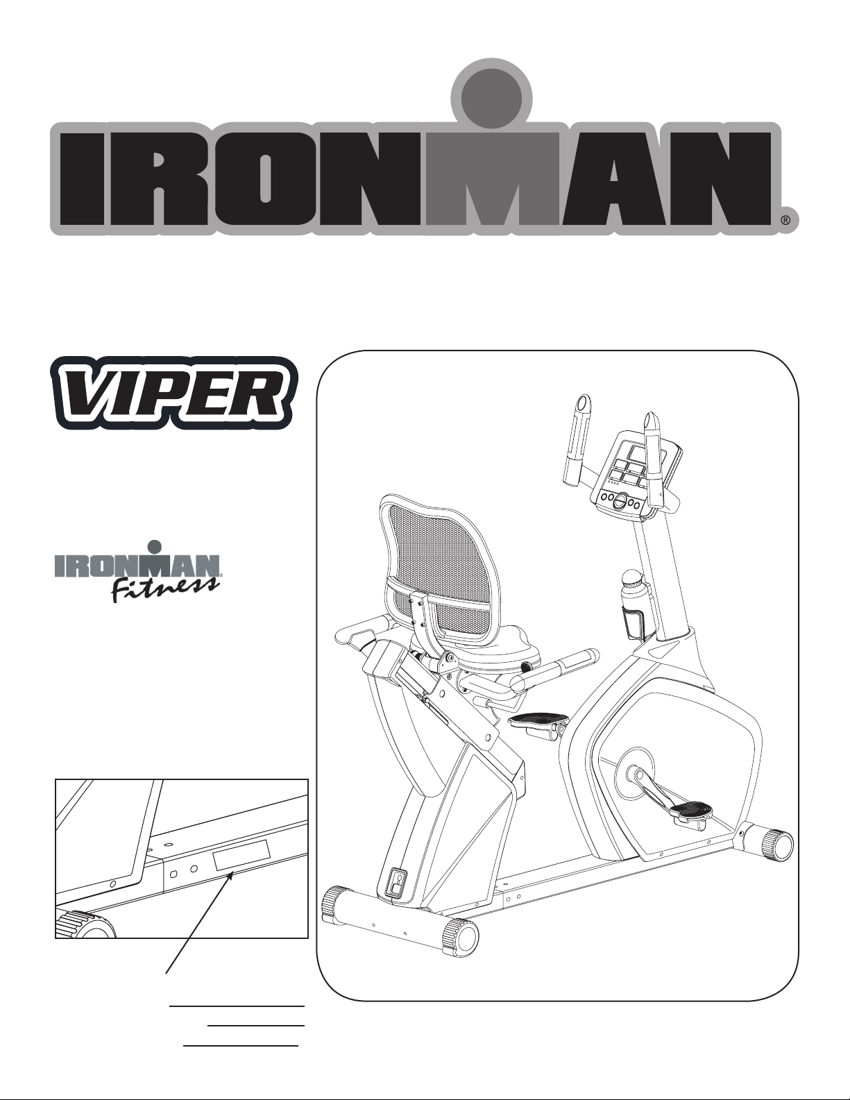
Model Name: Viper
Date of Purchase:
Serial Number:
315-00109
07/07 Rev A
Page 2

Table of Contents
Important Safety Information 3-4
Parts Identifier 5-6
Assembly 7-12
Console Instructions 13-17
Monitoring Your Heart Rate 18
Warm-Up Exercises 19
General Instructions 20
Moving Instructions 21
Parts List 22
Exploded Views 23
Warranty Information 24
2
Page 3

Important Safety Information
WARNING! Before using this unit or starting any exercise program, consult your physician.
This is especially important for persons over the age of 35 and/or persons with pre-existing
health problems. The manufacturer or distributor assumes no responsibility for personal injury
or property damage sustained by or through the use of this product.
WARNING! To reduce the risk of electrical shock, burns, fire, or other possible injuries to the
user, it is important to review this manual and the following precautions before operation.
SAFETY PRECAUTIONS AND TIPS
1. It is the owner's responsibility to ensure that all users of this unit have read the Owner's
Manual and are familiar with warnings and safety precautions.
2. This unit has a user maximum capacity of 300 pounds.
3. The unit should only be used on a level surface and is intended for indoor use only. The unit
should not be placed in a garage, patio, or near water and should never be used while you are
wet. Ironman Fitness recommends a mat be placed under the unit to protect floor or carpet
and for easier cleaning.
4. Follow safety information in regards to plugging in your unit. Do not run the power cord
underneath your unit. Do not operate the unit with a damaged or frayed power cord.
5. Wear comfortable, good-quality walking or running shoes and appropriate clothing. Do not
use the unit with bare feet, sandals, socks or stockings.
6. Always examine your unit before using to ensure all parts are in working order.
7. Allow the unit to fully stop before dismounting.
8. Pets should never be allowed near the unit.
9. Do not leave children unsupervised near or on the unit.
10. Never operate the unit where oxygen is being administered, or where aerosol products are
being used.
11. Never insert any object or body parts into any opening.
12. For safety and to prevent damage to your unit, no more than one person should use the
unit at a time.
13. Always unplug the unit before cleaning and/or servicing. Service to your unit should only be
performed by an authorized service representative, unless authorized and/or instructed by the
manufacturer.
14. Failure to follow these instructions will void the unit warranty.
3
Page 4
Important Safety Information
Thank you for purchasing the Ironman Fitness Viper Recumbent Bike! The quality product
you have chosen was designed to meet your needs for cardiovascular exercise. Before you
start, please read the Owner’s Manual and become familiar with the operation of your new unit.
Remember to take time to perform stretching exercises, provided in this manual, to help avoid
injury.
If you are taking medication, consult your physician to see what effect the medication will have
on your exercise heart rate.
If you have heart problems, you are not active, and/or are over the age of 35 years, do not
use the pre-set programs or start an exercise program without first contacting and receiving
approval from your physician.
To avoid the risk of electrical shock, always keep the console dry. Do not spill liquids on the
console. Ironman Fitness recommends a sealed water bottle for beverages consumed while
using the unit.
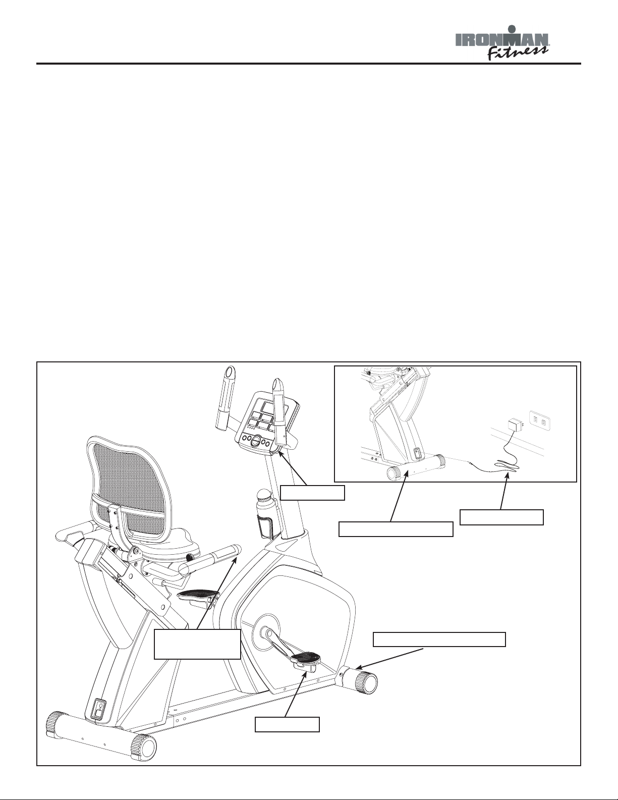
Please review the following drawing below to familiarize yourself with the listed
parts.
PULSE GRIP
HANDLEBARS
CONSOLE
AC ADAPTER
REAR STABILIZER
FRONT STABILIZER
PEDAL
4
Page 5
Parts Identifier
Seat Slide
Adjustment
Handle
Main Frame
Front
Rear
Handle Bar
Console
Front Stabilizer
Rear Stabilizer
Main Support Tube
Back
Rest
Seat Pad
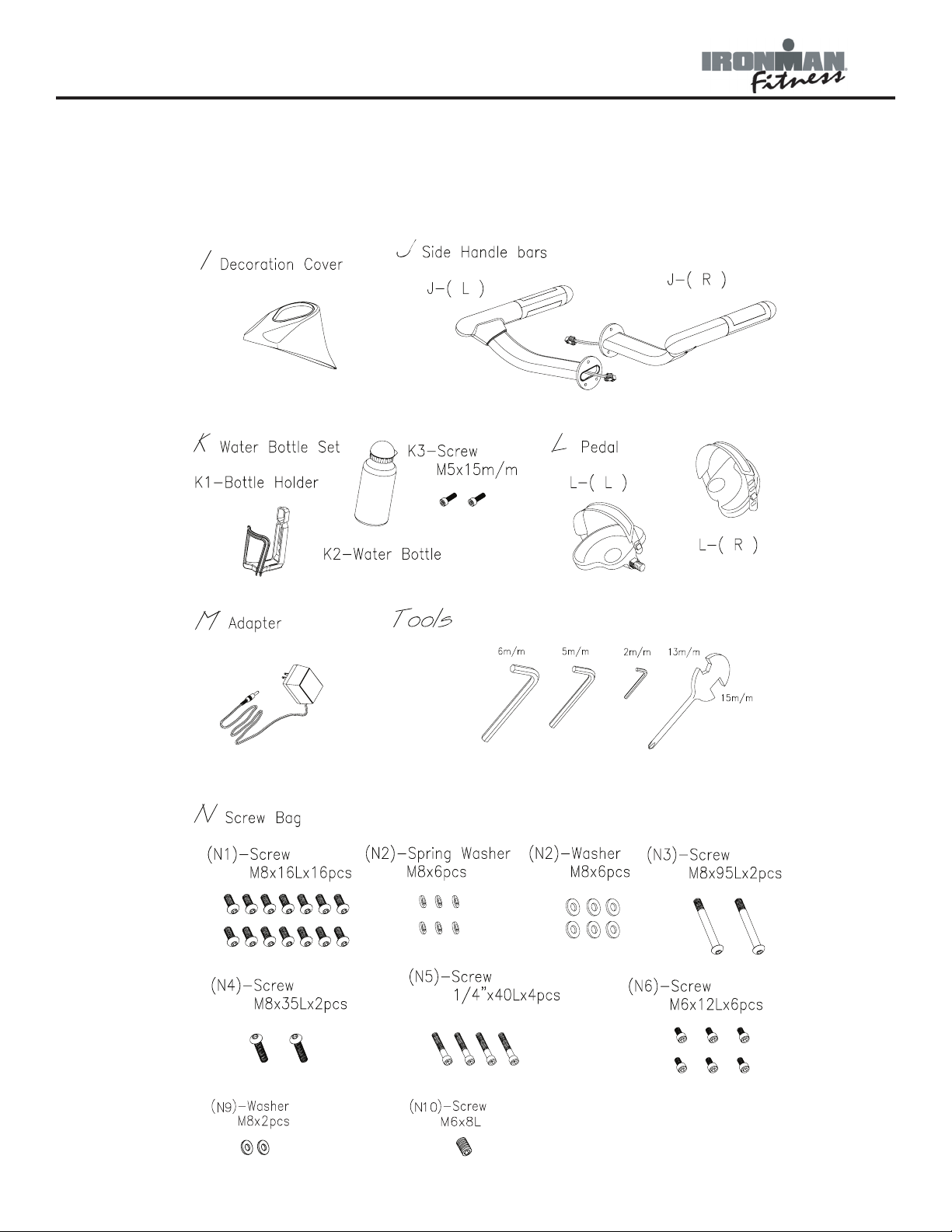
INSTRUCTIONS FOR ASSEMBLY:
Unpack the box in a clear area. Check to make sure all components are present and in good
condition. Do not dispose of the packing material until the assembly is completed. Tools have
been provided for you to use when assembling this product.
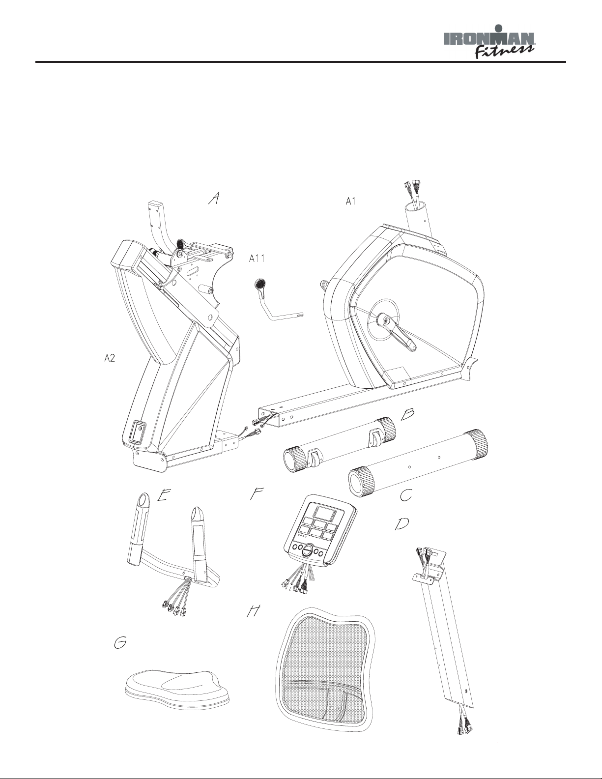
Locate the hardware pack and identify the following parts required for assembly.
5
Page 6
Parts Identifier
INSTRUCTIONS FOR ASSEMBLY:
Unpack the box in a clear area. Check to make sure all components are present and in good
condition. Do not dispose of the packing material until the assembly is completed. Tools have
been provided for you to use when assembling this product.
6
Page 7
Assembly
N8
N2
N3
Getting Started - The Ironman Fitness Viper Recumbent Bike will require some assembly.
Unpack the box in a clear area. Remove packing material. Do not dispose of packing material
until assembly is complete and unit is working properly. Place the unit on a clean level surface
for assembly. Make sure there is easy access to an electrical outlet. Before assembling, the
unit should be placed as close as possible to its final location. If you are missing any parts,
please call Ironman Fitness at 1-800-750-4766. Tools have been provided to assist with product assembly.
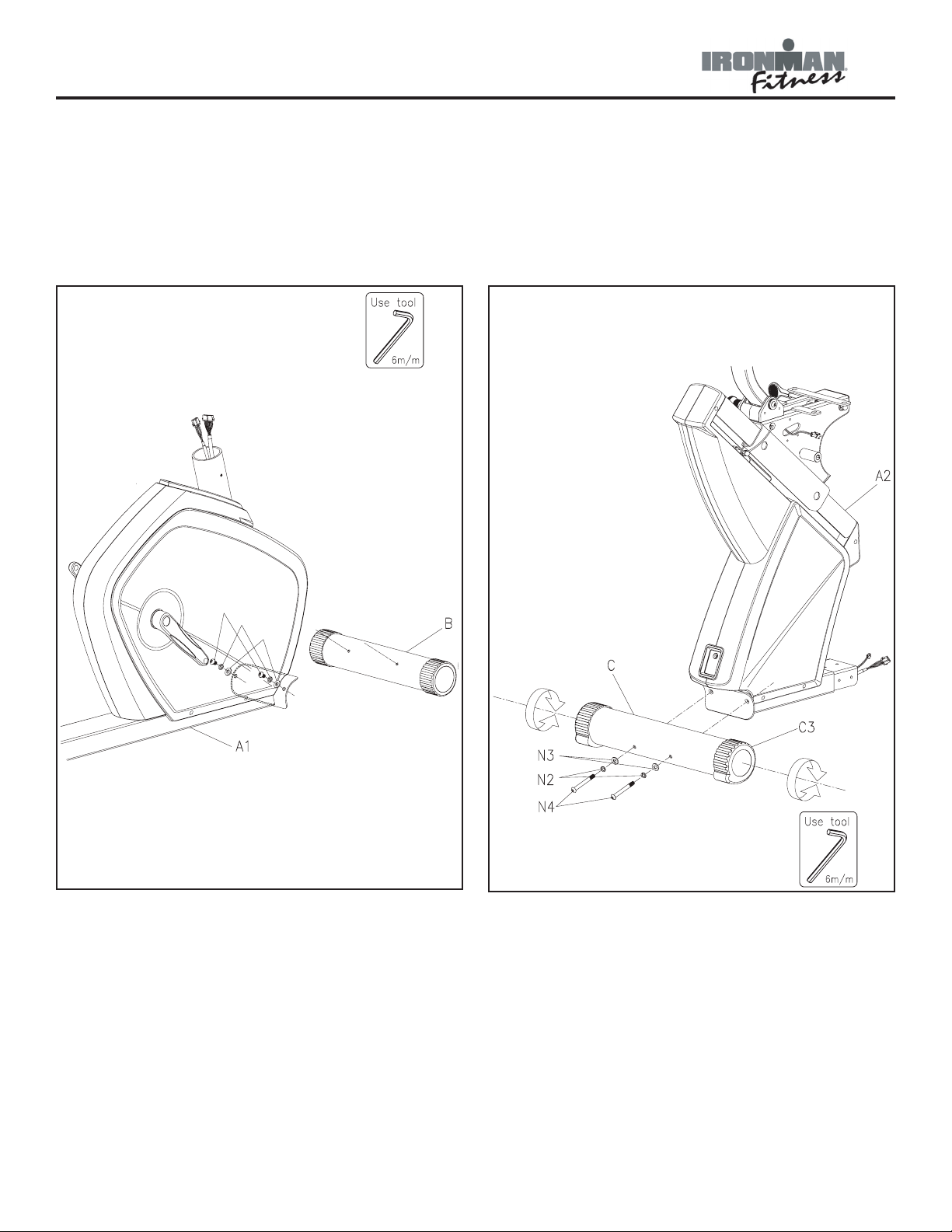
Figure 1
Figure 2
Figure 1
Step 1:
Secure front stabilizer bar (B) to main
frame (A1) using two bolts (N1), spring
washers (N2) and two washers (N3).
Note: Bolts will already be installed onto
the front stabilizer.
Figure 2
Step 1:
Secure rear stabilizer (C) to the main
frame (A2) using bolts (N4), two spring
washers (N2) and two washers (N3),
already attached to stabilizer.
7
Page 8
Assembly
D
I
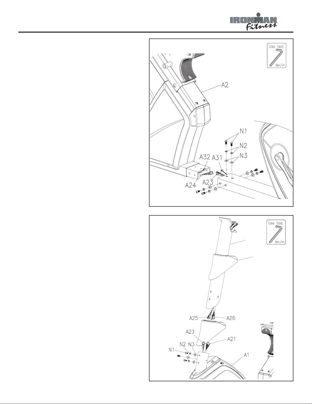
Figure 3
Step 1:
Connect hand pulse sensor wire-rear (A24)
to the hand pulse sensor wire-middle (A23).
Connect the power cord (A31) to power
cord (A32).
Step 2:
Locate the front (A1) and rear (A2) main
frames. Connect both front and rear
frames. To secure, use six bolts (N1), six
spring washers (N2) and six washers (N3) make sure all holes are lined up correctly.
Note: Ensure that all wires are secure
inside tube during the entire time both
frames are being secured. Be careful not to
pinch wires.
Figure 3
Figure 4
Step 1:
Locate main support tube (D) and console
tube cover (I). Slide main tube cover up
the main support tube.
Step 2:
Connect hand pulse sensor wire - front
(A25) coming from main support tube to
hand sensor wire - middle (A23) coming
from the main frame.
Connect power wire (A26) coming from
main support tube (D) to power wire (A21)
coming from the main frame.
Step 3:
Secure main support tube to main frame
(A1) using four bolts (N1) and four spring
washers (N2) and two washers (N3). Slide
main support tube cover down until it meets
the main frame.
Figure 4
8
Page 9

Assembly
N10
A9
N3
A9
Figure 5
Step 1:
Slide the seat adjustment handlebar (A11)
into the main frame and secure using stopping screw (N10).
Step 2:
Connect sensor wire (A32) to sensor wire
(J1) and side handlebar (J-R) onto sliding
track (A9). Secure using three bolts (N7).
Figure 5
Figure 6
Step 1:
Connect sensor wires (A32) to sensor wire
(J1) and side handlebar (J-L) onto sliding
track (A9). Secure using three bolts (N7).
Step 2:
Locate seat pad (G) and secure onto slid-
ing track (A9) with four screws (N1) and
four washers (N3).
Note: Screws are attached underneath seat
pad.
Figure 6
9
Page 10

Assembly
N9
E
N5
Figure 7
Step 1:
Locate backrest (H) and secure onto the
backrest tube (A10) using four screws (N6).
Step 2:
Locate plastic bottle holder (K1) and
secure to the middle of the main support
tube (D) using two screws (K3). Place
water bottle (K2) into water bottle holder
(K1).
Figure 7
Figure 8
Step 1:
Locate small handlebar (E) and attach
onto the iron plate of the console tube (D)
and use two bolts (N5) and two washers
(N9) to secure tightly.
Figure 8
10
Page 11

F
Assembly
Figure 9
Step 1:
Locate console (F), and connect sensor
wires (E5, A25, A26, E6, E7) to the wires
coming from the console.
Step 2:
Gently push all of the wires into the con-
sole tube. Slide console onto the console
tube. Secure using two screws (F1).
Note: Screws (F1) will already be attached
on the backside of the console. Remove
before sliding onto console tube.
Figure 9
Figure 10
Step 1:
Thread the right pedal (L-R) into the right
crank area of main frame (A1). Secure in
place by turning it clockwise to tighten.
Note: Right pedal (L-R) is marked with an
“R”.
Step 2:
Thread the left pedal (L-L) into the left
crank area of main frame (A1). Secure in
place by turning it counter-clockwise to
tighten.
Note: Left Pedal (L-L) is marked with an “L”
Figure 10
11
Page 12

Assembly
CONGRATULATIONS!
You have completed assembly of your Viper Recumbent Bike.
12
Page 13

Console Instructions
Take a few moments to review the console layout. Below is an overview of the console and
their different functions.
CONSOLE BUTTONS
MODE:
This button is used as an enter key, and will allow user to move to the next setting that can be
changed. When pressed and held for 2 seconds or more, console will go back to the user profile selection screen.
RESET:
This button is used to return to program selection screen when workout is paused.
START/STOP:
This button is used to start or stop training.
RECOVERY:
This button is used to begin the Recovery feature of the console (refer to "Console Functions"
for more information).
UP/DOWN:
When changing settings of a program, these buttons are used to increase/decrease TIME,
13
Page 14

Console Instructions
WEIGHT and AGE. During your workout, these buttons are used to increase/decrease the
resistance level from 1 to 16. Press and hold for two seconds to rapidly increase/decrease values.
BUTTONS ON UPRIGHT HANDLEBAR
In order to offer more flexibility during your workout, additional toggle switches are placed on
the upright handlebar. The buttons are the +/- and MODE. They are used the same way as
the buttons on the console. These buttons may be used at anytime as a substitute to pressing
the buttons located on the console.
CONSOLE FUNCTIONS
TIME:
If a target time was not selected, time will count up from 00:00 to maximum 99:59. When
working out with a target time, time will count down from target to 00:00. When selecting
target time, use the +/- buttons, the time will change in 1 minute increments and can range
from 1:00 min to 99:00 mins.
SPEED:
Displays current training speed from 0.0 to maximum 99.9 KM or MPH.
RPM:
Displays current training revolutions per minute.
DISTANCE:
If a target distance was not selected, distance will count up from 0.00 to maximum 99.90.
When working out with a target distance, distance will count down from target to 0.0. When
selecting target time, use the +/- buttons, the distance will change in 0.1 mile increments and
can range from 0.00 miles to 99.90 miles.
CALORIES:
If target calories were not selected, calories will count up from 0 to maximum 990. When
working out with target calories, calories will count down from target to 0. When selecting
target calories, use the +/- buttons, the calories will change in 10 calorie increments and can
range from 0 calories to 990 calories.
PULSE:
Displays your current heart rate as soon as both hands are holding the pulse sensor. The monitor will detect your heart rate through hand grip sensors that are located on the upright and
near the seat. Note: It may take several seconds for the electronics to detect and display an
accurate heart rate reading.
WATT:
Displays current training watt figures. A watt is a measurement of the amount of power generated by the user based on the resistance and speed.
14
Page 15

Console Instructions
RECOVERY:
After your workout, keep holding on hand grips and press “RECOVERY” button. All function display will stop except “TIME” starts counting down from 01:00 to 00:00. Screen will display
your heart rate recovery status rating between F1-F6. F1 is the best, F6 is the worst. User may
keep exercising to improve the heart rate recovery status. (Press the RECOVERY button again
to return the main display.)
GENERAL INFORMATION
1. Start pedaling or press any button to start Console.
2. The console will shut down after 4 minutes of no activity, and will display room temperature.
Begin pedaling or press any button to bring console back to operational state.
3. To reset console press and hold the MODE or RESET button for 2 seconds.
4. To begin workout without inputting any values (Quick Start Mode), simply press START/STOP
once the console is turned on. Change resistance during workout by pressing the +/-buttons.
Note: The values calculated or measured by the console are for exercise purposes only, not for
medical purposes.
GETTING STARTED
When console is first turned on, user will be able to select a user profile. There are four profiles to choose from, U1-U4. Each profile allows the user to enter his/her information, such as
Gender, Age, Height and Weight.
To begin, first select desired profile (U1-U4) that will be edited. Press MODE button to confirm
selection. The console will now allow user to select his/her gender. Use the +/- buttons on
the console or on the upper handlebars to select user's gender. Press MODE to confirm selection. Next, enter user's age. Use the +/- buttons on the console or on the upper handlebars
to select user's age. Press MODE to confirm selection. The console will now allow user to
enter his/her height. Use the +/- buttons on the console or on the upper handlebars to select
user's height. Note: Height will be shown in inches. Press MODE to confirm your selection.
Finally, enter user's weight. Use the +/- buttons on the console or on the upper handlebars to
select user's weight. Press MODE to confirm selection. The console remembers these settings
until the power is lost or disconnected, at which point, the console will revert back to default
settings.
PROGRAM INSTRUCTIONS
Once profile is either created or selected, user will select the type of workout desired. The
available workouts include Manual, Program, Watt, User and HRC.
MANUAL PROGRAM:
After selecting user profile, use the +/- buttons until the red light is blinking next to Manual.
The manual program allows the user to manually adjust tension settings throughout his/her
workout. The default tension level is 1. You may set desired time, distance, calories, resistance, distance, and pulse rate for your workout. If desired, user may bypass all of this, and
simply press START/STOP button and enter into quick start mode.
15
Page 16

Console Instructions
Program Goal
55% HRC Weight Loss
75% HRC Cardio
90% HRC Performance
TRG HRC Custom
Time will flash in the display. Use the +/- buttons to set desired time. Press MODE to confirm selection. Repeat steps for distance, pulse, resistance, and calories. Press START/STOP to
begin exercising at any time. You can change the tension level at any time during your workout
session by pressing the +/- buttons.
PROGRAMS:
The console comes with 12 preset programs (see program profiles on page 17 for programs
available). After selecting user profile, use the +/- buttons until Program is selected (the blinking red light will be next to the word Program). Press MODE button to confirm selection. Use
the +/- buttons until desired program is blinking (P1-P12). Press MODE button to confirm
selection. The console will now allow user to select the level of workout (resistance shown as
L1-L10) by using the +/- buttons until the desired level is selected. Press MODE button to confirm selection. Time will flash in the display. Use the +/- buttons to set desired time. Press
MODE to confirm selection. Repeat steps for distance, pulse, resistance, and calories. Press
START/STOP to begin exercising at any time. You can change the level at any time during your
workout session by pressing the +/- buttons.
USER PROGRAM:
The console allows user to customize a workout session. This program is divided into 15 segments. Resistance can be set for each segment. The program will be stored in the console’s
memory after set-up.
After selecting user profile, use the +/- buttons until User Setting is selected (the blinking red
light will be next to the word User Setting). Press MODE button to confirm selection. The first
segment will now be flashing in the main window. Use the +/- buttons to increase or decrease
the desired resistance. Press the MODE button to confirm selection and proceed to the next
segment. Repeat until all segments contain desired resistance.
HEART RATE PROGRAM (HRC):
Heart rate control programs are designed to automatically change resistance to keep your
heart rate at a predetermined level based on the selected Heart Rate program. Each heart rate
program is designed with a specific goal in mind. Note: This calculation is based on your age
which must be entered correctly into your user profile.
See MONITORING YOUR HEART RATE section for more information.
After selecting user profile, use the +/- buttons until Program is selected (the blinking red light
will be next to the word Program). Press MODE button to confirm selection. Use +/- to select
desired HRC Program. There are four different programs - heart rate 55% HRC (Heart Rate
Control), 75% HRC, 90% HRC, and Target HRC (user specifies the percentage of maximum
heart rate desired). Press MODE button to confirm selection.
16
Page 17

Console Instructions
If TRG is selected, use the +/- buttons until desired target heart rate is selected. Press
MODE button to confirm selection.
Time will flash in the display. Use the +/- buttons to set desired time. Press MODE to confirm
selection. Repeat steps for distance, pulse, resistance, and calories. Press START/STOP to
begin exercising at any time.
Note: For a more accurate reading, hold the hand grips with both hands. This is
especially important in Heart Rate Mode.
PROGRAM PROFILES
17
Page 18

Monitoring Your Heart Rate
Monitoring Your Heart Rate
To obtain the greatest cardiovascular benefits from your exercise workout, it is important to
work within your target heart rate zone. The American Heart Association (AHA) defines this
target as 60%-75% percent of your maximum heart rate.
Your maximum heart rate may be roughly calculated by subtracting your age from 220. Your
maximum heart rate and aerobic capacity naturally decreases as you age. This may vary from
one person to another, but use this number to find your approximate effective target zone. For
example, the maximum heart rate for an average 40 year-old is 180 bpm. The target heart
rate zone is 60%-75% of 180 or 108-135 bpm. See Fitness Safety below.
Before beginning your workout, check your normal resting heart rate. Place your fingers lightly
against your neck, or against your wrist over the main artery. After finding your pulse, count
the number of beats in 10 seconds. Multiply the number of beats by six to determine your
pulse rate per minute. We recommend taking your heart rate at these times; at rest, after
warming up, during your workout and two minutes into your cool down, to accurately track
your progress as it relates to better fitness.
During your first several months of exercising, the AHA recommends aiming for the lower part
of the target heart rate zone-60%, then gradually progressing up to 75%.
According to the AHA, exercising above 75% of your maximum heart rate may be too strenuous unless you are in top physical condition. Exercising below 60% of your maximum will result
in minimal cardiovascular conditioning.
Check your pulse recovery rate – If your pulse is over 100 bpm five minutes after you stop
exercising, or if it’s higher than normal the morning after exercising, your exertion may have
been too strenuous for your current fitness level. Rest and reduce the intensity next time.
Fitness Safety The Heart Rate chart indicates average rate zones for different ages. A variety
of different factors (including medication, emotional state, temperature and other conditions)
can affect the target heart rate zone that is best for you. Your physician or health care professional can help you determine the exercise intensity that is appropriate for your age and condition.
(MHR) = Maximum Heart Rate
(THR) = Target Heart Rate
220 - age = maximum heart rate (MHZ)
MHZ x .60 = 60% of your maximum heart rate.
MHZ x .75 = 75% of your maximum heart rate.
For example, if you are 30 years old, your calculations will be as
follows:
220 - 30 = 190
190 x .60 = 114 (low end or 60% of MHZ)
190 x .75 = 142 (high end or 75% of MHZ)
30 year-old (THR) Target Heart Rate would be 114-142
18
Page 19

Warm Up Exercises
EXERCISE GUIDELINES
WARNING! Before beginning this or any exercise program, you should consult your physician.
This is especially important for individuals over the age of 35 or individuals with pre-existing
health problems.
Warming up prepares the body for the exercise by increasing circulation, supplying more oxygen to the muscles and raising body temperature. Begin each workout with 5 to 10 minutes of
stretching and light exercise to warm up. The photos on this page show several forms of basic
stretching you may perform before your workouts. In order to achieve an adequate warm-up,
perform each stretch three times.
TOE TOUCH STRETCH
Stand, bending your knees slightly and slowly bend forward from
your hips. Allow your back and shoulders to relax as you reach
down toward your toes as far as possible. Hold for 15 counts,
then relax. This will stretch your hamstrings, back of knees, and
back.
HAMSTRING STRETCH
Sit with one leg extended. Bring the sole of the opposite foot
toward you and rest it against the inner thigh of your extended
leg. Reach toward your toes as far as possible. Hold for 15
counts, then relax. This will stretch your hamstrings, lower back,
and groin.
CALF/ACHILLES STRETCH
With one leg in front of the other, reach forward and place your
hands against a wall. Keep your back leg straight and your back
foot flat on the floor. Bend your front leg, lean forward and move
your hips toward the wall. Hold for 15 counts, then relax. To
cause further stretching of the Achilles tendon, bend your back
leg as well. This will stretch your calves, Achilles tendons, and
ankles.
QUADRICEPS STRETCH
With one hand against a wall for balance, reach back and grasp
one foot with your other hand. Bring your heel as close to your
buttocks as possible. Hold for 15 counts, then relax. This will
stretch your quadriceps and hip muscles.
INNER THIGH STRETCH (Image not Shown)
Sit with the soles of your feet together and your knees outward.
Pull your feet toward your groin area as far as possible. Hold for
15 counts, then relax. This will stretch your quadriceps and hip
muscles.
19
Page 20

General Instructions
How To Use The Seat Adjustment Bar To Find A Proper Seat Position
Push the seat slide adjustment handle forward, then slide the seat up and
down until desired position is found. When desired position is found, pull the
adjustment handle back into the upward position.
How To Adjust The Backrest
Push the bar located underneath the seat backward to adjust the backrest to desired position. Release the bar when desired position is found.
20
Page 21

Moving Instructions
Caution! To reduce the possibility of injury while lifting, bend your legs and keep
your back straight. As you lean the unit, lift using your legs, not your back.
First, kneel down and grasp the rear support tube with both hands. Next, with a firm grasp on
rear support tube stand up bringing the rear of the bike up in the air and tilt the unit until it
rolls freely on the transport wheels. Using extreme caution, move the unit to the desired location. Do not attempt to move the unit over an uneven or rough surface.
Note: This unit may not be identical to your unit.
21
Page 22

Ref # Parts # DESCRIPTION Qty Ref # Parts # Descritption Qty
A1 323-00586 FRONT MAIN FRAME 1 A29 302-01538 SCREW, HEXAGON 8X25MM 2
A2 323-00592 REAR MAIN FRAME 1 A30 319-00386 COVER, FOR CRANK 2
A3 319-00382 ALUMINUM TRACKING 1 A31 313-00426 POWER CORD FRONT 1
A4 306-00975 FRONT LEFT CHAIN COVER 1 A32 313-00427 POWER CORD REAR 1
A5 306-00976 FRONT RIGHT CHAIN COVER 1 A32-1 302-01561 NUT A32-1 1
A6 319-00391 REAR LEFT CHAIN COVER 1 A33 306-00959 COVER, DECORATION FOR CORD STAND 1
A7 319-00392 REAR RIGHT CHAIN COVER 1 A34 302-01563 SCREW, HEXAGON 4X12MM 1
A8 306-00965 COVER, FOR SLIDING TRACKING 1 A35 305-00233 SENSOR PIPE HOUSING 1
A9 319-00394 SLIDING TRACK 1 A36 302-01537 SCREW, FIXING A36 1
A9-1 306-00974 WHEEL 4 A37 302-01541 WASHER, FLAT A37 2
A9-2 302-01536 SCREW, FIX FOR WHEEL-A9-2 4 A38 302-01565 NUT, NYLON A38 3
A9-3 302-01560 METAL BUSHING, A9-3 2 A39 302-01535 SCREW, CROSS FOR MOTOR A39 4
A9-4 310-00247 FIXING PIN 1 A40 302-01543 SCREW, HEXAGON A40 1
A9-5 302-01571 SPRING A9-5 1 A41 302-01548 SCREW, HEXAGON A41 1
A9-6 302-01564 NUT M16 A9-6 1 A42 302-01534 SCREW, CROSS-A42 2
A9-7 323-00598 PULL BAR 1 A43 302-01556 SCREW, HEXAGON A43 6
A9-8 306-00966 END CAP 1 A44 302-01576 SCREW, TAPPING A44 34
A9-9 306-00980 LEFT DECORATION FOR REAR TUBE 1 A45 302-01546 SCREW, HEXAGON A45 1
A9-10 306-00981 RIGHT DECORTATION FOR REAR TUBE 1 A46 302-01549 SCREW, HEXAGON A46 1
A10 323-00580 BACKREST TUBE 1 A47 302-01645 SCREW, HEXAGON M4X20MM 4
A10-1 319-00412 AXLE FOR BACKREST TUBE 1 A48 302-01646 SCREW, HEXAGON M4X12MM 6
A10-2 302-01542 WASHER FLAT A10-2 2 A49 302-01647 SCREW, HEXAGON 8X5/8 4
A10-3 306-00967 END CAP FOR BACKREST TUBE 1 A50 302-01648 SCREW, HEXAGON M8X70MM 1
A11 323-00581 SEAT ADJUSTMENT HANDLE 1 A51 302-01649 WASHER, FLAT M8X16X1.2 2
A11-1 306-00979 PLASTIC WRAP 1 A52 302-01650 WASHER, FLAT 17X22X.3 2
A11-2 305-00232 CONNECTING HOUSING 1 A53 302-01651 WASHER, FLAT M6X16X1.2 1
A11-4 319-00384 AXLE FOR BRAKING 1 B1 323-00597 FRONT STABILIZER 1
A11-5 302-01527 BUSHING-L A11-5 1 B2 306-00968 END CAP FOR FRONT TUBE 1
A11-6 302-01528 BUSHING-R A11-6 1 B3 306-00973 TRANSPORATION WHEEL 2
A11-7 328-00081 BRAKE PAD 1 C1 323-00593 REAR STABILIZER 1
A11-8 319-00385 BRAKING STOPPER 1 C2 306-00970 END CAP FOR REAR TUBE LEFT 1
A11-9 302-01574 SCREW, STOPPING A11-9 2 C3 306-00969 END CAP FOR REAR TUBE RIGHT 1
A11-10 302-01532 C CLIP- A11-10 1 D 306-00977 MAIN SUPPORTING TUBE 1
A12 310-00245 GAS CYLINDER, FOR TRACKING BASE ADJUST 1 E 323-00587 FRONT SMALL HANDLE BAR 1
A12-1 302-01579 PLASTIC BUSHING 2 E1-1 323-00589 COVER, FOR LEFT HANDLE BAR LEFT 1
A13 310-00246 GAS CYLINDER, FOR BACKREST ADJUST 1 E1-2 323-00590 LEFT HANDLE BAR COVER RIGHT 1
A13-1 302-01578 PLASTIC BUSHING 2 E2-1 305-00235 RIGHT HANDLE BAR COVER(L) 1
A13-2 310-00248 GAS CYLINDER BAR 1 E2-2 305-00234 RIGHT HANDLE BAR COVER ® 1
A13-3 306-00978 PLASTIC WRAP 1 E2-3 302-01652 SCREW, HEXAGON M3X15MM 2
A13-4 302-01544 SCREW, HEXAGON A13-4 1 E3-1 323-00584 CONTROLLER FOR LEFT HANDLE BAR FRONT 1
A13-5 302-01562 NUT, A13-5 2 E3-2 323-00583 CONTROLLER FOR LEFT HANDLE BAR BACK 1
A14 311-00104 FLYWHEEL 1 E3-3 307-00730 PLASTIC CIRCUIT BOARD LEFT 1
A14-1 302-01655 WASHER, FLAT 10X13X.3 7 E4-1 323-00585 CONTROLLER FOR RIGHT HANDLE BAR FRONT 1
A14-2 302-01656 WASHER, FLAT 30X34X.8 1 E4-2 323-00582 CONTROL FOR RIGHT HANDLE BAR REAR 1
A14-3 302-01531 C CLIP-A14-3 2 E4-3 307-00731 PLASTIC CIRCUIT BOARD RIGHT 1
A14-4 302-01539 NUT, FLANGE A14-4 2 E5 313-00424 HAND PULSE SENSOR WIRE 2
A14-5 302-01638 NUT, FLANGE 3/8X3T 1 E6 313-00430 SENSOR WIRE LEFT 1
A14-6 302-01639 NUT, FLANGE 3/8X5T 1 E7 313-00431 SENSOR WIRE RIGHT 1
A15 319-00390 PRESSING PIPE 1 E8-1 313-00420 HAND PULSE 8
A15-1 302-01567 PRESSING SPRING A15-1 1 E8-2 328-00082 PAD FOR HAND PULSE 8
A15-2 331-00118 BEARING 2 E8-3 302-01568 SCREW E8-3 8
A15-3 319-00389 PIPE 3 E9 302-01569 SCREW E9 2
A15-4 302-01540 WASHER, FLAT A15-4 3 F 307-00729 MONITOR 1
A15-5 302-01547 SCREW, HEXAGON A15-5 3 F1 302-01533 SCREW, CROSS-F1 2
A15-7 302-01529 C CLIP C12 1 G 328-00084 SEAT, VIPER 1
A15-8 302-01641 WASHER M6X19X1.5 1 H 323-00579 BACKREST 1
A16 302-01559 HOUSING-MAGNET A16 1 I 306-00962 COVER, FOR MAIN SUPPORTING TUBE 1
A16-1 302-01570 SPRING A16-1 1 J-( L ) 323-00591 LEFT SIDE HANDLE BAR 1
A16-2 302-01580 TENSION CABLE, VIPER 1 J-( R ) 323-00596 HANDLE BAR, FOR RIGHT SIDE 1
A16-3 302-01642 SCREW, HEXAGON M6X60MM 1 J1 313-00423 HAND PULSE SENSOR WIRE 2
A16-4 302-01643 NUT, FLANGE M6 1 J2-1 306-00961 COVER, HANDLE BAR UPPER LEFT 1
A16-5 302-01644 NUT, FLANGE M6 1 J2-2 306-00960 COVER, HANDLE BAR DOWN LEFT 1
A17 302-01526 BELT PULLEY A17 1 J3-1 306-00964 COVER, HANDLE BAR UPPER RIGHT 1
A17-1 319-00383 AXLE FOR BELT PULLEY 1 J3-2 306-00963 COVER, HANDLE BAR DOWN RIGHT 1
A17-2 302-01530 C CLIP- A17-2 2 J4 306-00971 END CAP FOR SIDE HANDLE BAR 2
A17-3 302-01558 MAGNET A17-3 1 K1 302-01632 BOTTLE HOLDER, VIPER 1
A17-4 302-01550 SCREW, HEXAGON A17-4 4 K2 302-01633 BOTTLE HOLDER, VIPER 1
A17-5 304-00030 BELT 6PJ 46 1 K3 302-01634 SCREW M8*9.5, VIPER 2
A17-6 302-01566 NUT, NYLON A17-6 4 M 313-00419 ADAPTOR 1
A18 331-00119 BEARING 2 N1 302-01545 SCREW, HEXAGON N1 16
A19 306-01023 END CAP 40X80MM 1 N2 302-01572 WASHER, SPRING N2 6
A20 306-01024 END CAP 40X100MM 1 N3 302-01577 WASHER N3 6
A21 307-00732 MOTOR, VIPER 1 N4 302-01551 SCREW, HEXAGON N4 2
A22 313-00429 SENSOR WIRE 1 N5 302-01553 SCREW, HEXAGON N5 2
A23 313-00421 HAND PULSE SENSOR MIDDLE 1 N6 302-01552 SCREW, HEXAGON N6 4
A24 313-00422 HAND PULSE SENSOR REAR 1 N7 302-01555 SCREW, HEXAGON N7 6
A25 313-00425 HAND PULSE SENSOR FRONT 1 N8 302-01653 SCREW, HEXAGON M8X20MM 2
A26 313-00428 SENSOR WIRE 1 N9 302-01654 WASHER, FLAT M6X8MM 2
A27 319-00387 CRANK LEFT 1 N10 302-01575 SCREW, HEXAGON M6X8MM 1
A28 319-00388 CRANK RIGHT 1 # 302-01582 BOLT PACK, VIPER 1
Viper Recumbent Bike Parts List Rev
B
Parts List
22
Page 23

5N
3-
2
E
3-2E
3N
3
N
1
5
A
54A
1
N
3
x7N
8
4
A
7
4
A
7
4A
1
N
8
4
A
8
4A
7x44A
64A
9
4
A
94A
8N
2N
3
N
4N
2
N
3N
6
4
A
2
N
3N
25
A
84
A
64
A
7N
05
A
6
4
A
6
4A
6
4
A
5
x44
A
6
4
A
64
A
3
5A
8
5
1A
5
-6
1
A
9-51A
4
x
6
N
9
N
9N
01N
1-41A
2
4
1
A
3-41
A
5
41
A
4-41A
6
-41
A
91A
02
A
4-
5
1A
A17-5
A16
-4
1
A
A10-3
Exploded View
23
Page 24

Residential and Personal Use Limited Warranty
PLEASE READ THESE WARRANTY TERMS AND CONDITIONS FULLY AND CAREFULLY BEFORE USING YOUR IRONMAN FITNESS
EQUIPMENT. BY USING THE EQUIPMENT, YOU ARE CONSENTING TO BE BOUND BY THE FOLLOWING TERMS AND CONDITIONS.
Frame: Lifetime Electronics and *Parts: 1 yr Missing/Cosmetic Parts: 30 Days
Limited Warranty
This Limited Warranty applies in the United States and Canada to
Products manufactured or distributed by Ironman Fitness Products,
L.P. under the Ironman Fitness (“Ironman”) brand name (as used
herein, the “Product” or “Products”). The warranty period to the
original purchaser is listed above, and commences on the date of
original purchase of the product, unless otherwise authorized by
Ironman. Ironman warrants that the Product purchased from
Ironman or from an authorized Ironman Fitness reseller “dealer” (for
residential or personal use only, unless otherwise authorized by
Ironman in writing), is free from defects in Materials and
Workmanship relevant to the functionality of the Product at initial
startup, under normal use, and during the applicable warranty period,
unless otherwise determined by Ironman.
This warranty ex
cludes expendable parts if primary cause for
warranty claim is wear. Expendable parts pertain to components on
the Product that are prone to normal wear and tear. These items
vary by Product, and can include (but not limited to) hand grips, skid
pads, pedals, pedal straps, poly-v belts, console overlays, toggle
switch/button overlays, (luster free or dull) ekg plates, decals, and
any other items that are not essential to the operation of the Product,
unless otherwise determined by Ironman.
This warranty extends only to you, the original purchaser. It is not
transferable to anyone who subsequently purchases (or receives as a
gift) the Product from you. Your sales receipt, showing the
date/place of purchase and serial number (if applicable) of the
Product, is your proof of purchase, and may be required by Ironman
any time a warranty parts (or service) claim is made or if no
warranty record exists for the product.
Exclusive Remedies
During the warranty period listed above, Ironman will repair a
Product by correcting any minor issues (either by phone or online
support) that might be causing the Product failure. Should a
technical service and support representative be unable to correct
the issue, Ironman may replace the parts (with new parts or at the
option of Ironman, with serviceable used parts, that are equivalent
to new parts in performance) that become defective, malfunction, or
otherwise fail to conform to this Limited Warranty under normal use.
Replacement parts shall be warranted for 30 days from the shipment
reception date or through the end of the ‘replaced’ part warranty
period, whichever is longer. Any replacement parts, required past
the warranty period listed above, shall be subject to purchase at
retail price, plus any added shipping and handling charges associated
to the delivery of the part. Note that replacement parts may be
available only through the lifetime (as defined) of the Product. In
conforming to this warranty, Ironman (as the manufacturer)
reserves the right to change manufacturers or vendors of any part to
cover the existing warranty.
Ironman may also provide service (if deemed necessary and if
applicable) at no charge to you during (and not to exceed) the
service warranty period listed above, in an attempt to repair the
Product. Should the Product require service at your request or out of
the limited warranty period, Ironman can furnish contact information
for local (to your area) Ironman authorized service providers.
Service quotes, costs, and scheduling will be strictly dependent on
service provider rates and mutual (consumer/provider) service
agreements. Ironman is not responsible for any service repair costs
accrued through the use of authorized Ironman service providers at
your request or out of the limited warranty period (without written
consent from Ironman), beyond the limitations outlined on this
warranty.
Replacements and Returns
If after a reasonable number of attempts, a defect has not been repaired (or
the Product is deemed non-repairable by Ironman technical service and
support staff), Ironman, based on a case by case review, may opt to replace
the Product, or recommend an alternate resolution, such as a warranty
buy-out (Product cost, subject to deduction of a reasonable charge for usage)
or a credit. Ironman, as a manufacturer, reserves the right to replace the
Product with a Factory-Reconditioned Product that meets or exceed
standards comparable to those of the replaced Product.
The warranty covering the replacement Product shall expire on the
date the original warranty for the replaced Product would have expired,
unless otherwise determined by Ironman.
Conditions and Restrictions
This warranty DOES NOT (A) cover shipping and handling charges,
export taxes, custom duties and taxes, or any other charges associated
with transportation of the parts or Product, beyond the initial courtesy
period of 60 days from original date of purchase of the Product; (B)
extend to Products not purchased from Ironman or from an authorized
Ironman reseller; (C) extend to Products purchased from online auction
sites; (D) cover any extended, additional, or third party warranties if
not offered exclusively by Ironman in writing; (E) cover Products
installed at fee based facilities/commercial environments (gyms, homes
used as wellness centers, etc.); (F) cover Products installed in light
institutional environments (non fee-based facilities include for example,
and not be way of limitation, fire houses, police departments, rehab
centers, hospitals, clinics, apartment complexes, club houses, etc.); (G)
cover service calls to correct installation, perform maintenance, or
instruct owners on how to use the equipment; or (H) cover a Product
on which the serial number has been purposefully or accidentally
defaced or removed and there is no proof of purchase available (if serial
number is applicable), unless authorized by Ironman in writing or
otherwise stated on this warranty.
This Limited Warranty becomes void for Products that have been
damaged or rendered defective as a result of (a) accident, misuse, or
abuse (including but not limited to exceeding the Ironman listed,
maximum weight limit); (b) use of parts not manufactured or sold by
Ironman; (c) modification of the Product; (d) normal wear and tear; (e)
operation on incorrect power supplies; (f) ***failure to perform (or
performing improper) maintenance; (g) service by anyone other than
Ironman, or an authorized Ironman warranty service provider; (h)
floods, fires, earthquakes, lightning strikes, power surges, and other
unavoidable acts of nature; (j) residential mis-wires; or (k) incorrect
setup, installation, or assembly. Should any Product (submitted for
warranty parts replacement) be found ineligible under the terms
outlined on this warranty, an estimate for parts purchase (if available)
can be furnished at your request.
*Parts is herein defined exclusively, for all intents and purposes, and
pertaining to this Limited Manufacturer Warranty, as
components or
Materials essential to the functionality of the Product.
**Lifetime of a Product, is herein defined exclusively, for all intents and
purposes, and pertaining to this Limited Manufacturer Warranty, as the time
period 7 years beyond the end of production cycle of a Product in question.
Disclaimer and Release
EXCEPT AS EXPRESSLY SET FORTH IN THIS WARRANTY, IRONMAN MAKES
NO OTHER WARRANTIES, EXPRESSED OR IMPLIED, INCLUDING ANY
IMPLIED WARRANTIES OF MERCHANTABILITY AND FITNESS FOR A
PARTICULAR PURPOSE. IRONMAN EXPRESSLY DISCLAIMS ALL WARRANTIES
NOT STATED IN THIS LIMITED WARRANTY. ANY IMPLIED WARRANTIES THAT
MAY BE IMPOSED BY LAW ARE LIMITED TO THE TERMS OF THIS LIMITED
WARRANTY. NEITHER IRONMAN NOR ANY OF ITS AFFILIATES SHALL BE
RESPONSIBLE FOR INCIDENTAL OR CONSEQUENTIAL DAMAGES. SOME
STATES DO NOT ALLOW LIMITATIONS ON IMPLIED WARRANTIES OR THE
EXCLUSION OR LIMITATION OF INCIDENTAL OR CONSEQUENTIAL DAMAGES,
SO THE ABOVE LIMITATIONS OR EXCLUSIONS MAY NOT APPLY TO YOU.
THIS LIMITED WARRANTY GIVES YOU SPECIFIC LEGAL RIGHTS AND YOU
MAY ALSO HAVE OTHER RIGHTS THAT MAY VARY FROM STATE TO STATE.
THIS IS THE ONLY EXPRESS WARRANTY APPLICABLE TO
IRONMAN-BRANDED PRODUCTS. IRONMAN NEITHER ASSUMES NOR
AUTHORIZES ANYONE TO ASSUME FOR IT ANY OTHER EXPRESS WARRANTY.
Warranty Information
24
Page 25

Customer Service
1.800.750.IRON
1.800.750.4766
Ironman Fitness
4009 Distribution Drive
Suite 250
Garland, TX 75041
www.ironmanfitness.com
Ironman, Ironman Triathalon and M-dot are registered trademarks of the World Triathlon Corporation. This product is licensed by the Ironman Triathlon.
 Loading...