

Viper 300+ Installation Manual

Table of Contents
Experienced security installers may skip to Pg. 8, but read
all the italicized sections, as they describe changes and/or new features.
Installation Points to Remember Page 2
Deciding on Component Location 3
Finding the Wires you Need 5
Step-by-step meter instructions!
Making your Wire Connections 7
Primary Harness Diagram 8
Wire Connection Guide 9
Plug in LED and Valet®/Program Switch 11
Four-pin Shock Sensor Harness 11
Bypassing Sensor Inputs 12
Door Lock Wiring Diagrams 12-15
Transmitter/Receiver Learn Routine
™
16
Two-vehicle Operation with Single Transmitter 17
Operating-Settings Learn Routine
™
18
New Double Pulse Unlock Feature
Feature Descriptions 20
Nuisance Prevention®Circuitry 21
Valet®Mode 21
Table of Zones 22
Troubleshooting 22
INSTALLATION
GUIDE
Directed Electronics, Inc.
VVIIPPEERR
300
+
®
®
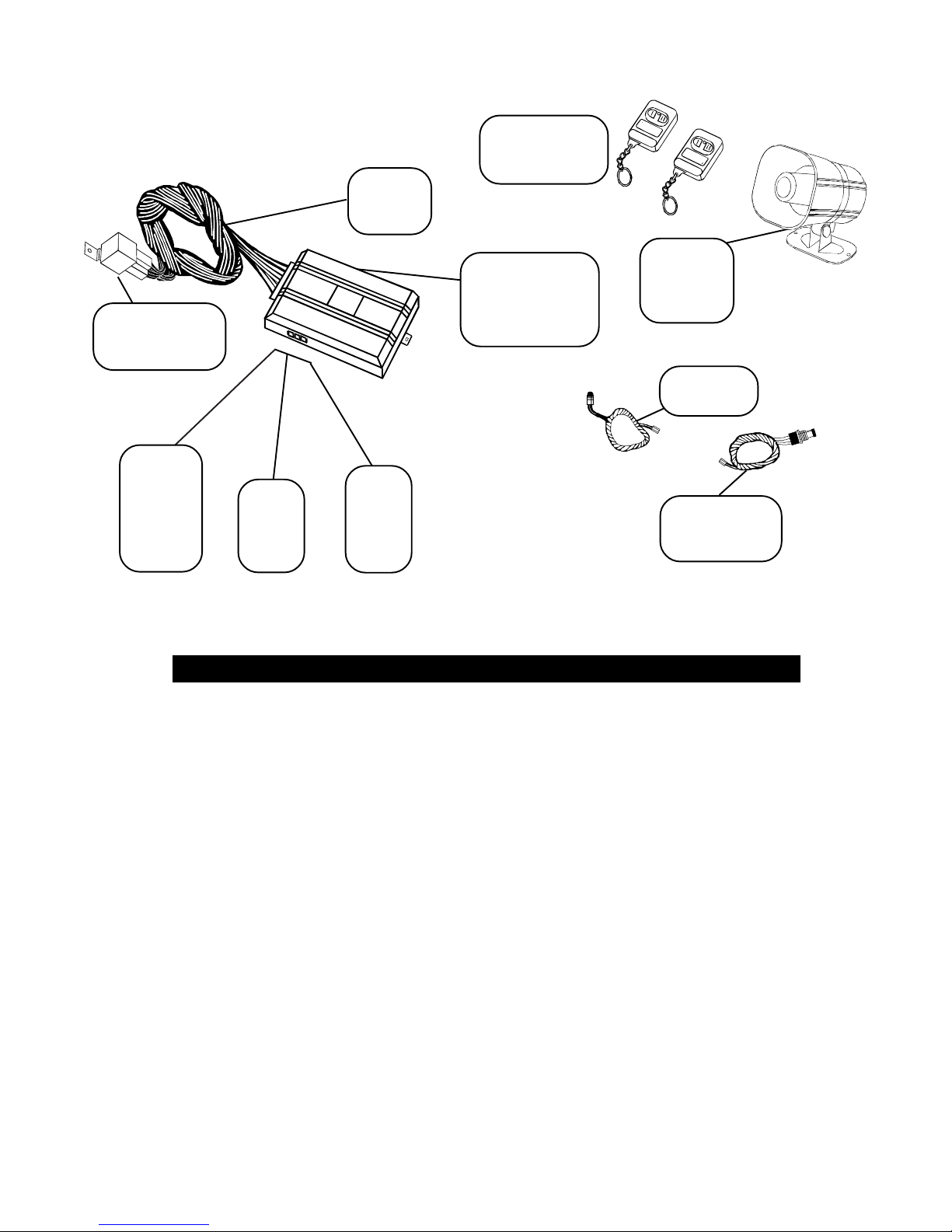
Primary
harness
H1
Two 471T
remote
transmitters
Pre-wired 8618
Starter Kill
Relay
2-pin
mini
blue
Valet®/
Program
plug
2-pin
micro
LED
plug
Stinger
™
Double
Guard™ Shock
Sensor
Adjustment
3-pin
2-wire
door
lock
harness
INSTALLATION POINTS TO REMEMBER
514T
Revenger
Soft Chirp
™
™
siren
Plug-in
Status LED
Plug-in
Valet®/Program
switch
Do not disconnect the battery if the vehicle has an antitheft-coded radio. If equipped with an air bag, avoid
disconnecting the battery if possible. IMPORTANT: Many airbag systems will display a diagnostic code through
their warning light after they lose power. Disconnecting the battery requires this code to be erased, a procedure
that can require a trip to the dealer.
Before beginning the installation:
• Check with the customer on Status LED location.
• Remove the domelight fuse. This prevents accidentally draining the battery.
• Roll down a window to avoid being locked out of the car.
After the install:
• Test all functions. The "Using Your System" section of the Owner's Guide is very helpful when testing.
• When testing, don’t forget that this system is equipped with Nuisance Prevention® Circuitry.
NPC™ can bypass trigger zones, making them appear to stop working. (See page 21)
© 1995,1997 Directed Electronics, Inc. Vista, CA 2 N432 1-98.PM6

Step One:
Deciding on Component Locations
Siren
Some things to remember when mounting the siren:
• Keep it away from heat sources. Radiators, exhaust manifolds, turbochargers, and heat shields are all
things to avoid.
• Mount it where a thief cannot easily disconnect it, whether the hood is open or shut. Both the siren and
its wires should be difficult to find. This usually involves disguising the wire to look like a factory harness.
• We recommend against grounding the siren to its
mounting screws. Instead, we recommend running
both the red and black wires into the passenger
compartment and grounding to one common point for
all devices. After all, both wires are the same length
and come already bonded together. Whenever
possible, conceal your wires in the factory harnesses
or in the same style loom as the factory.
• When possible, put the siren on the same side of the
vehicle as the control module, where its wires will
reach the control module’s wires without extending
them. Always run the wires through the center of a
grommet, never through bare metal!
• Point the siren down so water does not collect in it.
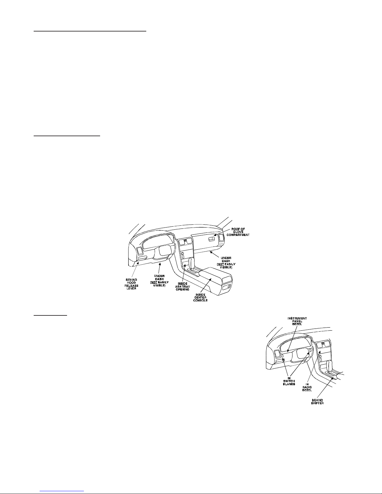
Control Module
Never put the control module in the engine compartment!
The first step in hot-wiring a vehicle is removing the driver's side underdash panel to access the starter and ignition
wires. If the control module is placed just behind the driver's side dash it can easily be disconnected.
When locating the control module, try to find a secure location that will not require you to extend the harnesses’ wires
(they are 1.5 meters long). Keep it away from the heater core (or any
other heat sources) and any obvious leaks.
The higher the control module is in the vehicle, the better the
transmitter range will be. If you put the control module under a seat
or inside a metal dashboard, range will suffer, and you may wish to
add a 542T Range Extending Antenna (available separately).
Some good control module locations: Above the glove box, inside the
center console, above the underdash fuse box, above the radio, etc.
© 1995,1997 Directed Electronics, Inc. Vista, CA 3 N432 1-98.PM6
Stinger® Doubleguard® Shock Sensor
How the control module is mounted is the single biggest factor in the performance of the on-board shock sensor. We
recommend two mounting methods: using double-sided tape or hook-and-loop fastener to mount to a trim panel or
an air duct, or wire-tying to a wire harness.
NOTE: In many vehicles, screwing the control module to metal will result in poor sensitivity, especially
on the rear of the vehicle.
If mounting the module where the sensor's adjustment screw cannot be easily reached for adjustment, hook-and-loop
fastening tape (such as Velcro) is recommended for ease of removal for future adjustments.
If the sensor must be temporarily bypassed for any reason, please see pg. 12.
Valet® Program Switch
Ensure that the location you pick for the switch has sufficient clearance to the rear. The switch should be well hidden.
It should be placed so passengers or stored items (such as in a glove box or center console) cannot accidentally hit
it. The switch fits in a 9/32" hole.
This system has Remote Valet®. The user can enter and exit Valet® Mode without having to reach the Valet®/program
switch. DEI® introduced this feature so that switch location was less critical in day-to-day use. As long as the
Valet®/program switch can be reached to disarm without a transmitter, easy access is not important.
IMPORTANT! When the vehicle is delivered, please show the user where the switches are located and
how to disarm the system with it.
Status LED
Things to remember when positioning the Status LED:
• It should be visible from both sides and the rear of the vehicle, if posible.
• It needs at least 1/2" clearance to the rear.
• It is easiest to use a small removable panel, such as a switch blank or
a dash bezel. Remove it before drilling your 9/32" hole.
• Use quick-disconnects near the LED wires if the panel is removable.
This lets mechanics or other installers remove the panel without cutting
the wires.
© 1995,1997 Directed Electronics, Inc. Vista, CA 4 N432 1-98.PM6
Optional Starter Kill Relay
If Starter Kill Relay or its connections are immediately visible upon removal of the underdash panel, they can easily
be bypassed. Always make the relay and its connections difficult to discern from the factory wiring! Exposed yellow
butt connectors do not look like factory parts, and will not fool anyone! For this reason, routing the starter kill wires
away from the steering column is recommended.
Step 2:
Finding the Wires You Need
Now that you have decided where each component will be located, you’re going to find the wires in the car that the
security system will be connected to.
IMPORTANT! Do not use a 12V test light to find these wires! All testing described in this manual is described
using a digital multimeter
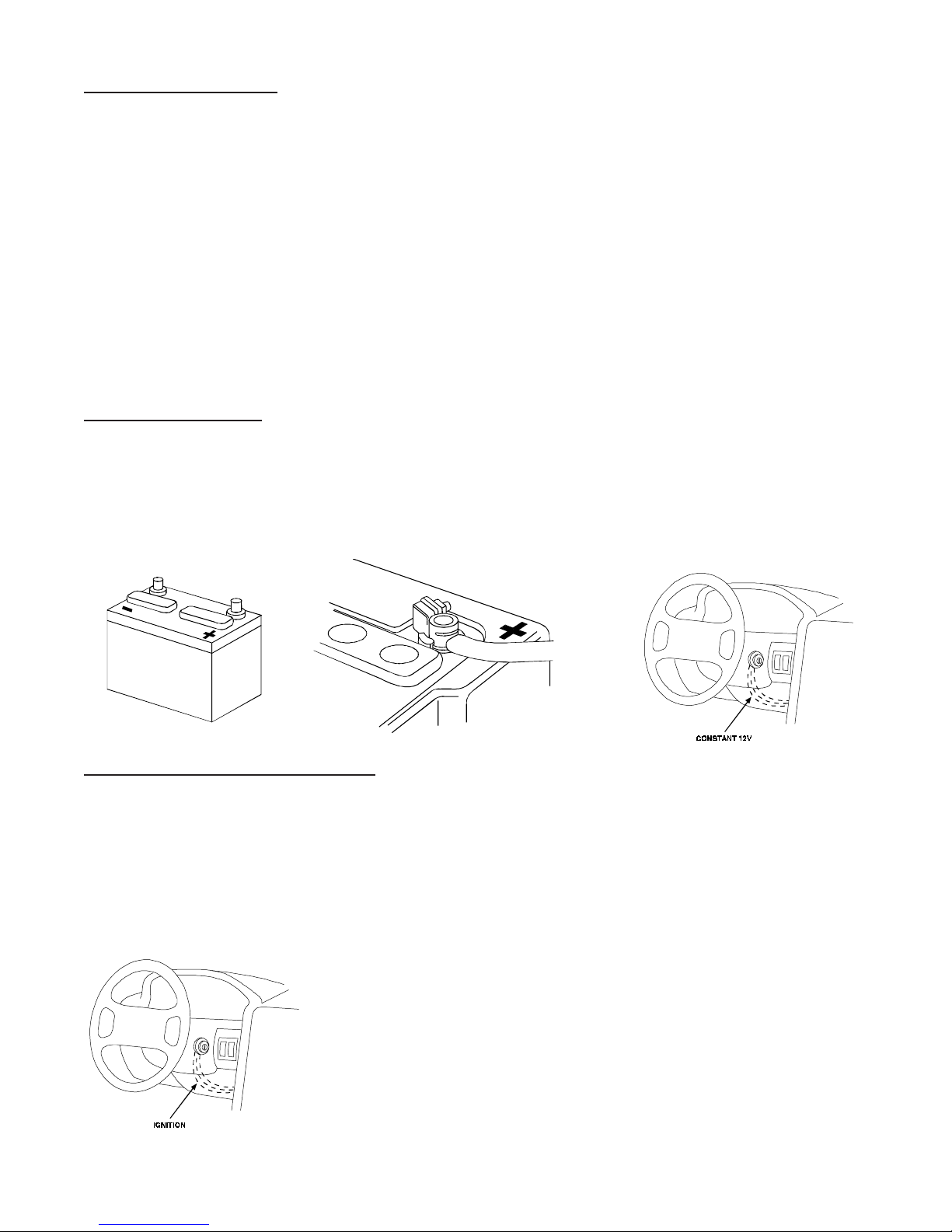
Obtaining Constant 12V
We recommend two possible sources for 12V constant: The (+) terminal of the battery, or the constant supply to the
ignition switch. Always install a fuse within 12 inches of this connection. If the fuse also will be powering other
circuits, such as door locks, a power window module, a Nite-Lite® headlight control system, etc.; fuse accordingly.
IMPORTANT! Do not remove the fuse holder on the red wire. It ensures that the control module has its own
fuse, of the proper value, regardless of how many accessories are added to the main power feed.
.
Finding the 12V Switched Ignition Wire
The ignition wire is powered when the key is in the run or start position. This is because the ignition wire powers the
ignition system (spark plugs, coil) as well as the fuel delivery system (fuel pump, fuel injection computer). Accessory
wires, on the other hand, lose power when the key is in the start position to make more current available to the starter
motor.
How to find (+)12V ignition with your multimeter:
1. Set to DCV or DC voltage (12V or 20V is fine).
2. Attach the (-) probe of the meter to chassis ground.
3. Probe the wire you suspect of being the ignition wire. The steering column
harness or ignition switch harness is an excellent place to find this wire.
4. Turn the ignition key switch to the run position. If your meter reads (+)12V,
go to the next step. If it doesn’t, probe another wire.
5. Now turn the key to the start position. The meter display should stay steady,
not dropping by more than a few tenths of a volt. If it drops close to or all
the way to zero, go back to step 3. If it stays steady at (+)12V, you have
found an ignition wire.
© 1995,1997 Directed Electronics, Inc. Vista, CA 5 N432 1-98.PM6
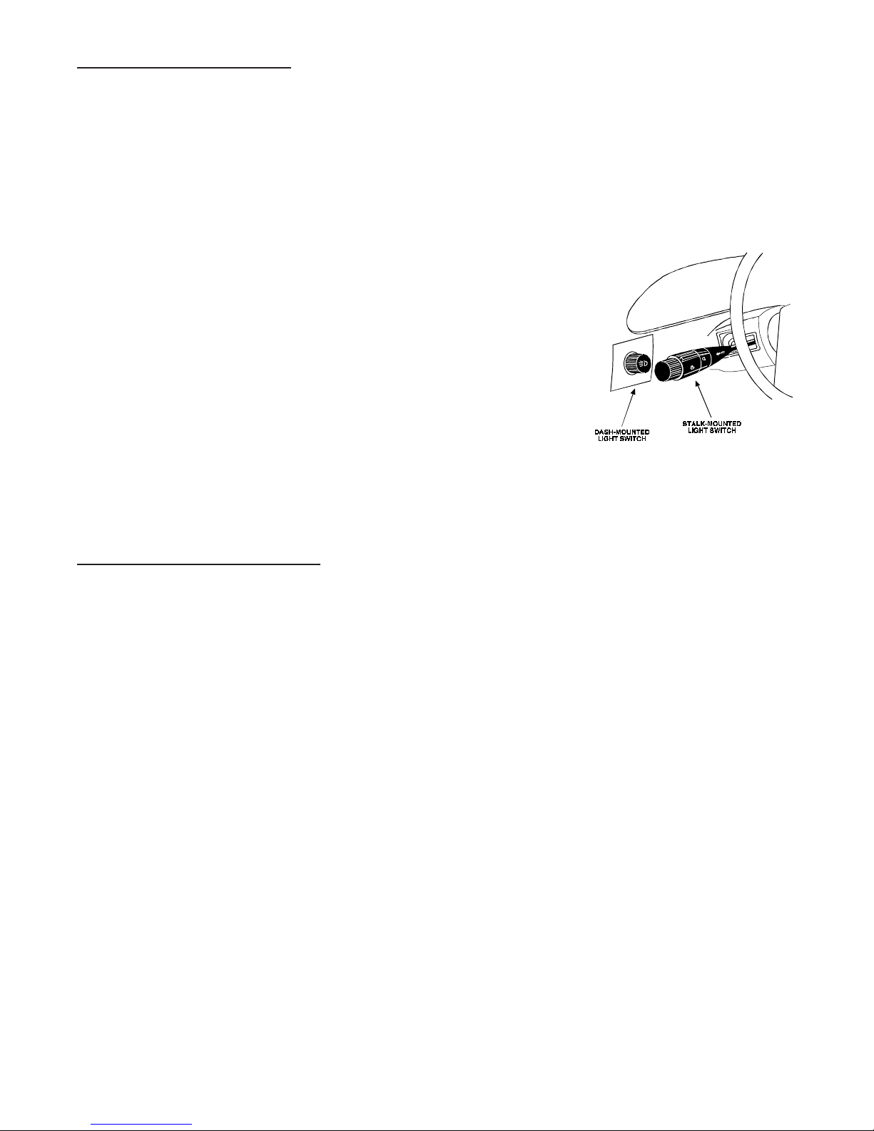
Finding a (+) Parking Iight Wire
The (+) parking light wire is often found near the switch. Many cars have the switch built into the turn signal lever, and
in these cars the parking light wire can be found in the steering column. The same wire is often available in the kick
panel or running board.
NOTE: Many Toyotas, as well as many other Asian vehicles, send a (-) signal from the switch to a relay. The
relay then sends 12V(+) to the bulbs. Whenever you have difficulty finding a (+) parking light wire near the
switch, simply test the wires at any switch or control panel
which is lit by the instrument panel lighting.
Remember, you need a (+) parking light wire that does not vary with dimmer setting.
How to find a (+) parking light flash wire with your multimeter
1. Set to DCV or DC voltage (12V or 20V is fine).
2. Attach the (-) probe of the meter to chassis ground.
3. Probe the wire you suspect of being the parking light wire. Usually,
the area near the headlight/parking light switch is an excellent area
to start, as is the kick panel.
4. Turn on the parking lights. If your meter shows (+)12V, turn off the
parking lights and make sure it goes back to zero.
5. If it does return to zero, turn the parking lights back on and, using the dash light dimmer control, turn the
brightness of the dash lights up and down.
look for another wire.
If it stays relatively close to (+)12V, you have found your parking light wire.
If the meter changes more than a volt when using the dimmer,
Finding the Door Pin Switch Circuit
The best places to find the door switch wire are:
At the pin switch: When testing at the pin switch, check the wire to ensure that it “sees” all the doors. Often,
the passenger switch will cover all the doors even if the driver’s switch will not.
At the dome light: This may not be your best choice if the vehicle has delayed domelight supervision, but
it will work in many Hondas, or any vehicle with completely diode-isolated pin switches.
Once you have determined the wire color, the easiest place to connect to the wire is often at the kick panel, at the
windshield pillar, or in the running board. When an easy location is not available, running a wire to the domelight itself
is often the best solution.
How to find a door pin switch trigger wire with your multimeter:
1. Set to DCV or DC voltage (12V or 20V is fine).
2. In most Fords, fasten the (-) probe of the meter to chassis ground. In most other cars, fasten the (+) probe
of your meter to (+)12V constant.
3. Probe the wire you suspect of being the door trigger wire. If the meter reads (+)12V when any door is
opened, you have found a trigger wire.
NOTE: Make sure the wire you use “sees” all the doors! Some newer GM vehicles lack standard-type
pin switches. The dome light in these vehicles is turned on when the door handle is lifted. These usually
have a blue/white or white coming out of the door into the kick panel which will provide a (-) trigger for
all doors. Some GM vehicles (some Cavaliers, Grand Ams, etc.) have a yellow wire coming out of the
door which provides a (+) door trigger.
© 1995,1997 Directed Electronics, Inc. Vista, CA 6 N432 1-98.PM6

How to find the (+)12V starter wire with your multimeter:
1. Set to DCV or DC voltage (12V or 20V is fine).
2. Attach the (-) probe of the meter to chassis ground.
3. Probe the wire you suspect of being the starter wire. The steering
column is an excellent place to find this wire. Remember you do not
need to interrupt the starter at the same point you test it. Hiding your
starter kill relay and connections is always recommended.
4. Turn the ignition key switch to the start position. Make sure the car is
not in gear! If your meter reads (+)12V, go to the next step. If it
doesn’t, probe another wire.
5. Cut the wire you suspect of being the starter wire.
6. Attempt to start the car. If the starter engages, reconnect it and go back to step 3. If the starter does not
turn over, you have the right wire.
Step 3:
Making Your Wire Connections
Before making your connections, plan how your wires will be routed through the vehicle. For instance, the yellow
ignition input, the red 12V constant input, and the orange ground-when-armed output (for the optional starter kill relay)
will often be routed together to the ignition switch harness. In order to keep the wiring neat and make it harder to find,
you may wish to wrap these wires together in electrical tape or conceal them in tubing similar to what the manufacturer
used.
There are two acceptable ways of making a wire connection: Solder connections and crimp connectors. When properly
performed, either type of connection is reliable and trouble-free. Regardless of whether you solder your connections
or you use mechanical-type crimp-on connections, ensure that all connections are mechanically sound and that they
are insulated.
Cheap electrical tape, especially when poorly applied, is not a reliable insulator. It often falls off in hot weather. Use
good-quality electrical tape or heat shrink.
Never
twist-and-tape the wires together without soldering.
Never
use “fuse taps,” as they can damage fuse box terminals.
If you use tapping connectors such as 3M T-Taps (not to be confused with Scotch-Locks), avoid using them in highercurrent applications (constant 12V, ground, etc.). Some tapping connectors are inferior in quality and should be
avoided.
© 1995,1997 Directed Electronics, Inc. Vista, CA 7 N432 1-98.PM6
 Loading...