

VIPColor VP2020 User Manual
VP2020
User Guide
Printer

Copyright © 2004 VIPColor Technologies Pte Ltd.
This document contains proprietary information that is protected by copyright. All rights are reserved. No part of this document
may be photocopied, reproduced, or translated to another language without the prior written permission of VIPColor
Technologies Pte Ltd.
Warranty
VIPColor Technologies Pte Ltd takes steps to ensure that this user guide is correct; however, errors may occur, and the
information in this guide is subject to change without notice.
VIPColor Technologies Pte Ltd. makes no warranty of any kind with regard to this material, including but not
limited to, the implied warranties of merchantability and fitness for a particular purpose.
VIPColor Technologies, Pte Ltd. shall not be liable for errors contained herein or for incidental or consequential damages in
connection with furnishing, performance, or use of this material.
Trademarks
Microsoft, Windows, Windows NT, Windows 2000, and Windows XP are registered trademarks of Microsoft Corporation in the
U.S.A. and/or other countries.
TrueType fonts are a registered trademark of Apple Computer, Inc.
PCL is a trademark of Hewlett-Packard Company
VIPColor is a trademark of VIPColor Technologies, U.S.A., Inc
All other company and product names may be the registered trademarks or trademarks of their respective owners.
VP2020 User Guide 05/2004
WARNING
Electrical Shock Hazard
Serious shock hazard leading to death or injury may result if you do not take the following precautions:
• Ensure that the AC power outlet (mains) has a protective earth (ground) terminal.
• Disconnect the printer from the power source prior to performing any troubleshooting procedures.
• Prevent water or any other liquids from running onto electrical components or circuits, or through openings in the enclosure.
ii

Contents
Parts of the Printer v
1 Setting up the Printer 1
Choose a location for the printer . . . . . . . . . . . . . . . . . . . . . . . . . . . . . . . . . . . . 1
Unpack the printer . . . . . . . . . . . . . . . . . . . . . . . . . . . . . . . . . . . . . . . . . . . . . . . 2
Connect the power cable. . . . . . . . . . . . . . . . . . . . . . . . . . . . . . . . . . . . . . . . . . 3
Install printheads and cartridges . . . . . . . . . . . . . . . . . . . . . . . . . . . . . . . . . . . . 4
Load continuous media . . . . . . . . . . . . . . . . . . . . . . . . . . . . . . . . . . . . . . . . . . . 8
Run the printhead alignment procedure . . . . . . . . . . . . . . . . . . . . . . . . . . . . . 15
Connect the printer to a computer . . . . . . . . . . . . . . . . . . . . . . . . . . . . . . . . . . 16
Connect the printer to a network . . . . . . . . . . . . . . . . . . . . . . . . . . . . . . . . . . . 17
Install the printer driver . . . . . . . . . . . . . . . . . . . . . . . . . . . . . . . . . . . . . . . . . . 20
Set up email warnings (optional) . . . . . . . . . . . . . . . . . . . . . . . . . . . . . . . . . . . 22
Install ink cartridges . . . . . . . . . . . . . . . . . . . . . . . . . . . . . . . . . . . . . . . . . . . 4
Install printhead cleaners. . . . . . . . . . . . . . . . . . . . . . . . . . . . . . . . . . . . . . . 5
Install printheads . . . . . . . . . . . . . . . . . . . . . . . . . . . . . . . . . . . . . . . . . . . . . 6
Enter TCP/IP parameters. . . . . . . . . . . . . . . . . . . . . . . . . . . . . . . . . . . . . . 18
2 Printing on Different Types of Media 23
About color profiles . . . . . . . . . . . . . . . . . . . . . . . . . . . . . . . . . . . . . . . . . . . . . 23
Load a new media roll . . . . . . . . . . . . . . . . . . . . . . . . . . . . . . . . . . . . . . . . . . . 24
Set the media selector . . . . . . . . . . . . . . . . . . . . . . . . . . . . . . . . . . . . . . . . 32
Change printer settings . . . . . . . . . . . . . . . . . . . . . . . . . . . . . . . . . . . . . . . 32
Barcode safe mode . . . . . . . . . . . . . . . . . . . . . . . . . . . . . . . . . . . . . . . . . . . . . 33
3 Printer Control Panel 35
Control panel display and buttons . . . . . . . . . . . . . . . . . . . . . . . . . . . . . . . . . . 35
Selecting printer options . . . . . . . . . . . . . . . . . . . . . . . . . . . . . . . . . . . . . . . . . 37
Entering a password . . . . . . . . . . . . . . . . . . . . . . . . . . . . . . . . . . . . . . . . . 37
Main menu. . . . . . . . . . . . . . . . . . . . . . . . . . . . . . . . . . . . . . . . . . . . . . . . . . . . 38
Summary of submenus and options . . . . . . . . . . . . . . . . . . . . . . . . . . . . . 39
Submenus and options . . . . . . . . . . . . . . . . . . . . . . . . . . . . . . . . . . . . . . . . . . 41
PRINTHEAD MAINTENANCE menu. . . . . . . . . . . . . . . . . . . . . . . . . . . . . 41
TEST menu . . . . . . . . . . . . . . . . . . . . . . . . . . . . . . . . . . . . . . . . . . . . . . . . 42
ADVANCED menu. . . . . . . . . . . . . . . . . . . . . . . . . . . . . . . . . . . . . . . . . . . 44
MAINTENANCE menu. . . . . . . . . . . . . . . . . . . . . . . . . . . . . . . . . . . . . . . . 46
iii

OPTIONS menu. . . . . . . . . . . . . . . . . . . . . . . . . . . . . . . . . . . . . . . . . . . . . 47
COUNTRY CONFIG menu . . . . . . . . . . . . . . . . . . . . . . . . . . . . . . . . . . . . 48
INTERFACE menu. . . . . . . . . . . . . . . . . . . . . . . . . . . . . . . . . . . . . . . . . . . 49
PASSWORD menu . . . . . . . . . . . . . . . . . . . . . . . . . . . . . . . . . . . . . . . . . . 50
4 Printer Internal Web Pages 51
Set up a connection. . . . . . . . . . . . . . . . . . . . . . . . . . . . . . . . . . . . . . . . . . . . . 51
Home page . . . . . . . . . . . . . . . . . . . . . . . . . . . . . . . . . . . . . . . . . . . . . . . . 53
Password. . . . . . . . . . . . . . . . . . . . . . . . . . . . . . . . . . . . . . . . . . . . . . . . . . . . . 54
Current Active Stock . . . . . . . . . . . . . . . . . . . . . . . . . . . . . . . . . . . . . . . . . . . . 55
Metrics . . . . . . . . . . . . . . . . . . . . . . . . . . . . . . . . . . . . . . . . . . . . . . . . . . . . . . . 56
Option Install . . . . . . . . . . . . . . . . . . . . . . . . . . . . . . . . . . . . . . . . . . . . . . . . . . 58
Test Functions . . . . . . . . . . . . . . . . . . . . . . . . . . . . . . . . . . . . . . . . . . . . . . . . . 61
Available Fonts . . . . . . . . . . . . . . . . . . . . . . . . . . . . . . . . . . . . . . . . . . . . . . . . 62
Set Up Email Warnings . . . . . . . . . . . . . . . . . . . . . . . . . . . . . . . . . . . . . . . . . . 63
Country Configuration . . . . . . . . . . . . . . . . . . . . . . . . . . . . . . . . . . . . . . . . . . . 65
5 Changing Cartridges and Printheads 67
Replace an ink cartridge . . . . . . . . . . . . . . . . . . . . . . . . . . . . . . . . . . . . . . . . . 68
Replace a printhead . . . . . . . . . . . . . . . . . . . . . . . . . . . . . . . . . . . . . . . . . . . . 69
Replace a printhead cleaner . . . . . . . . . . . . . . . . . . . . . . . . . . . . . . . . . . . . . . 73
6 Troubleshooting 75
Error messages on control panel. . . . . . . . . . . . . . . . . . . . . . . . . . . . . . . . . . . 75
If the carriage is unable to move . . . . . . . . . . . . . . . . . . . . . . . . . . . . . . . . 77
If the media is jammed in the printer . . . . . . . . . . . . . . . . . . . . . . . . . . . . . 77
Print quality problems . . . . . . . . . . . . . . . . . . . . . . . . . . . . . . . . . . . . . . . . . . . 80
Adjustments and calibrations. . . . . . . . . . . . . . . . . . . . . . . . . . . . . . . . . . . . . . 81
Printhead alignment. . . . . . . . . . . . . . . . . . . . . . . . . . . . . . . . . . . . . . . . . . 81
Media calibration . . . . . . . . . . . . . . . . . . . . . . . . . . . . . . . . . . . . . . . . . . . . 85
Printer maintenance . . . . . . . . . . . . . . . . . . . . . . . . . . . . . . . . . . . . . . . . . . . . 88
Clean contacts on the printhead . . . . . . . . . . . . . . . . . . . . . . . . . . . . . . . . 88
7 Optional Accessories 89
Expanding SDRAM . . . . . . . . . . . . . . . . . . . . . . . . . . . . . . . . . . . . . . . . . . . . . 90
Expanding flash memory . . . . . . . . . . . . . . . . . . . . . . . . . . . . . . . . . . . . . . . . . 91
8 Printer Specifications 93
Media dimensions and printable area . . . . . . . . . . . . . . . . . . . . . . . . . . . . . . . 95
iv
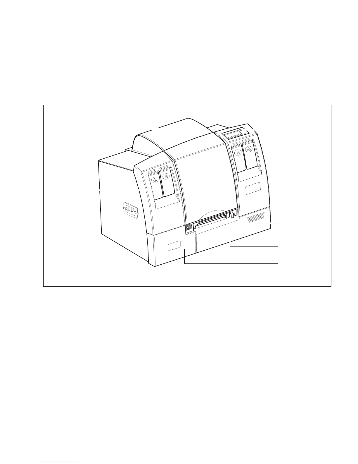
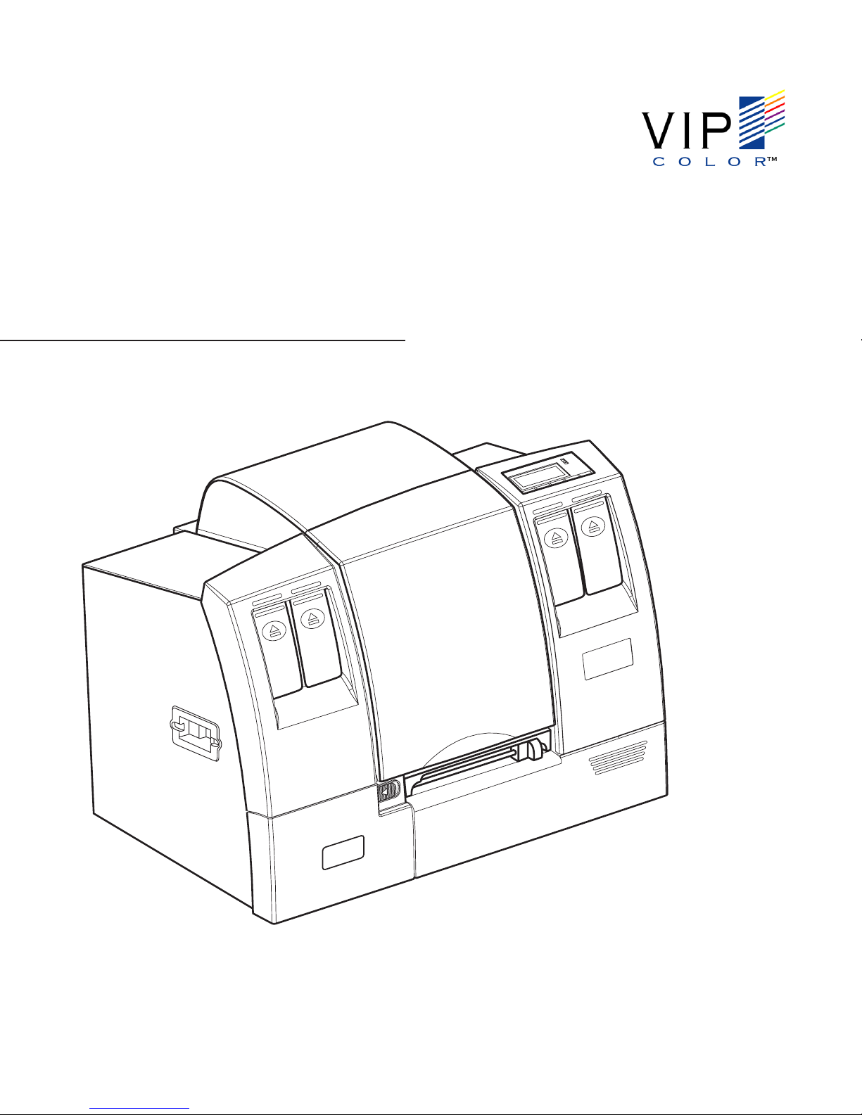
Parts of the Printer
The following figures show the locations and names of key printer parts.
top cover control panel
ink cartridge
front access door
manual cutter
service station
access door
v
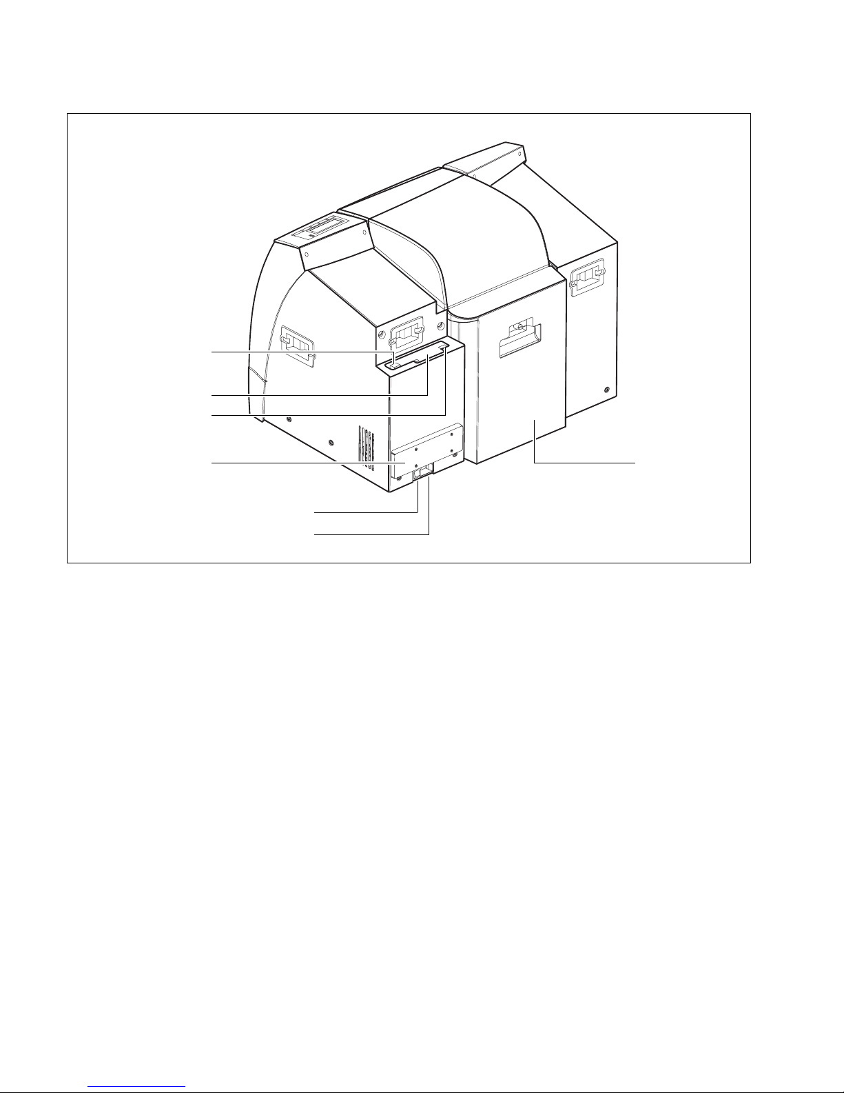
USB connector
PCMCIA slot
Ethernet connector
memory
expansion bay
* Always turn the printer off using the Power button on the control panel, to
ensure that the printhead carriage is returned to its proper position at the left side
of the printer.
rear access door
Power switch*
power socket
vi

Chapter 1
Setting up the Printer
To set up the printer, you need to do the following:
• Choose a suitable location for setting up the printer.
• Unpack the printer.
• Connect the power cable.
• Install the ink cartridges, printhead cleaners, and printheads.
• Load continuous media to run the printhead alignment procedure.
• Once complete, replace the continuous media with the media for printing.
• Connect the printer to your computer and/or network.
• Install the printer driver.
Choose a location for the printer
Select a suitable location for the printer, following these guidelines:
• The area must be well ventilated and clean.
• Avoid places where the printer can be exposed to direct sunlight, liquids or
chemicals.
• Avoid places that can be subject to abrupt changes in temperature and
humidity.
• Select a surface that is sturdy enough to take the weight of the printer.
NOTE: It is recommended that the printer be run on an uninterruptable power
supply.
SETTING UP THE PRINTER 1
Unpack the printer
When unpacking the printer, take care as it is heavy. You should always get help
from another person to unpack and lift the printer.
1. Carefully lift the printer out of the box and set it on a level and sturdy surface in
the selected location.
2. Open the top cover of the printer.
3. Push and hold the green lever to lift up the frame that supports the media roll.
4. Carefully remove the packing material inside the printer.
5. Push and hold the green lever to lower the frame, then close the printer cover.
You should see two smaller boxes containing the printheads and ink cartridges
inside the printer box.
Do not throw away the printer box and packing materials in case you need to use
them again.
2 SETTING UP THE PRINTER

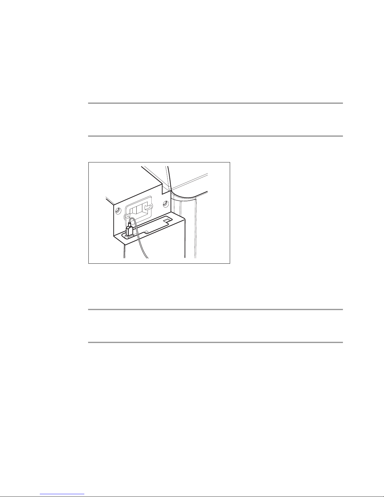
Connect the power cable
Power switch
NOTE: Make sure the packing material inside
the printer has been removed and the printer
cover is closed.
1. Attach the power cable securely to the printer
before plugging the other end into a power outlet.
2. Turn the printer on using the Power switch near
the power connector.
NOTE: Do not turn off the printer using the Power
switch at the back of the printer. Always turn it off
using the Power button on the control panel at the
front of the printer. This ensures that the printhead
carriage is returned to its proper position at the left
side of the printer and that the printheads are
protected.
SETTING UP THE PRINTER 3
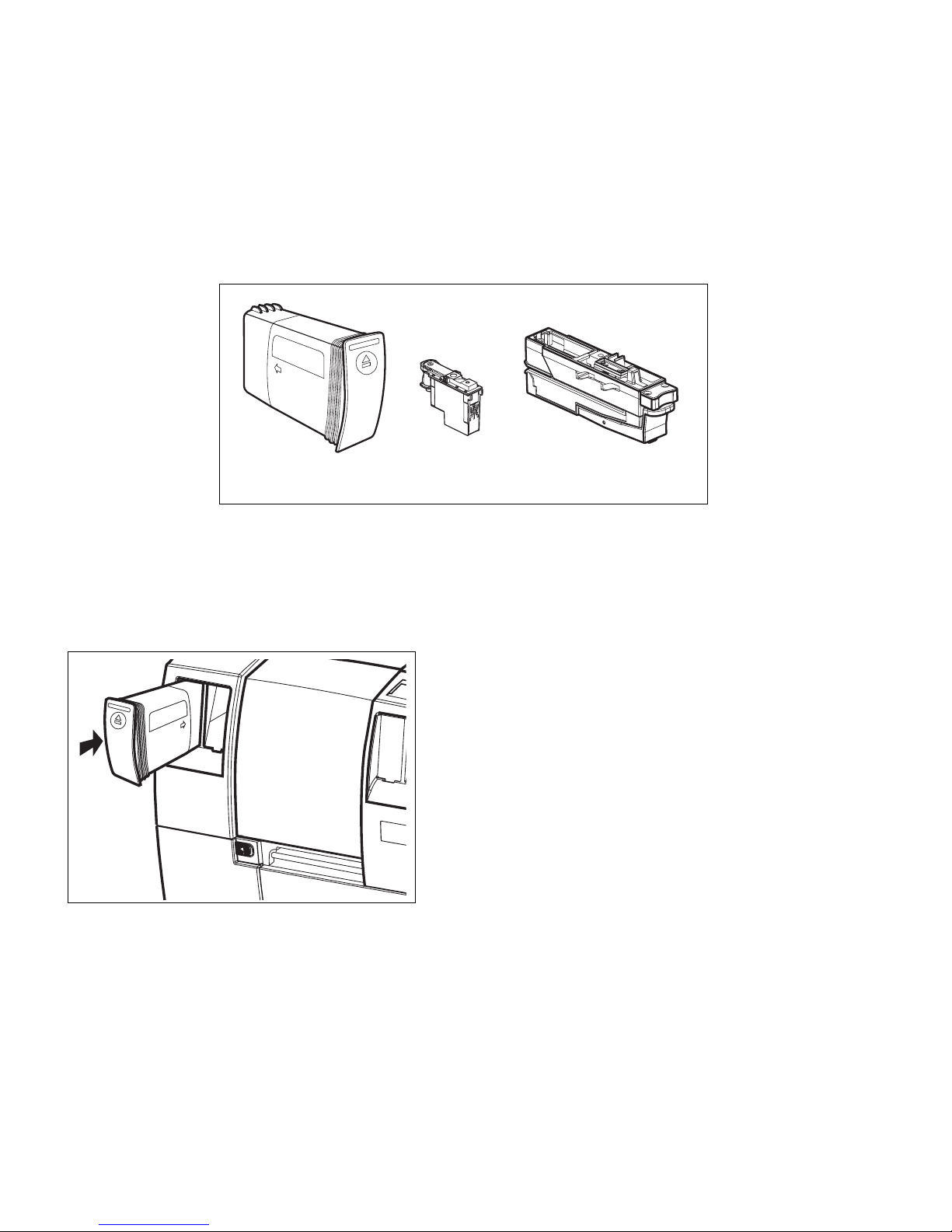
Install printheads and cartridges
The printer uses four ink cartridges (CMYK – Cyan, Magenta, Yellow and
blacK), five printheads, and five printhead cleaners (there are two black
printheads). The ink cartridges, printheads and printhead cleaners have to be
correctly installed before the printer will function properly.
Install ink cartridges
ink cartridge
printhead
Each color cartridge fits in a specific slot, as
indicated by the colored labels over the slots. From
left to right, the colors are magenta, yellow, cyan
and black.
1. Remove a cartridge from its packaging.
2. Push the cartridge firmly into the correct slot.
If you are not able to snap the cartridge in place, it
is probably in the wrong slot.
3. Install the other cartridges in the same way.
printhead cleaner
4 SETTING UP THE PRINTER
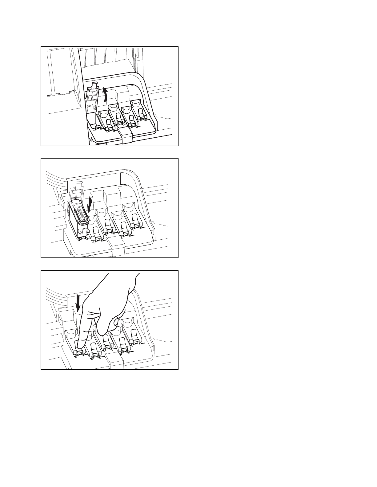
Install printhead cleaners
Each new printhead comes with a printhead cleaner.The printhead cleaners
protect the printheads when the printer is not in use, and keep the printheads
clean for optimum print quality. The printhead cleaners are installed in the
service station at the bottom left of the printer, below the printhead carriage.
Each printhead cleaner is designed to work with a particular color printhead. The
printhead cleaners must therefore be installed in the same order as the
printheads, as indicated by the colored labels on the service station. From left to
right, the colors are magenta, yellow, cyan, black and black.
1. Slide the lock to the right to release the service
station access door.
2. Remove the printhead cleaner from the
packaging.
3. Insert the printhead cleaner into the correct slot
in the service station and push it in firmly by its
top. You should hear a click as it snaps into place.
4. Install the other printhead cleaners in the same
way.
NOTE: When all the printhead cleaners are
installed, they do not line up.
5. Close the access door and slide the lock back to
the left to lock it.
SETTING UP THE PRINTER 5

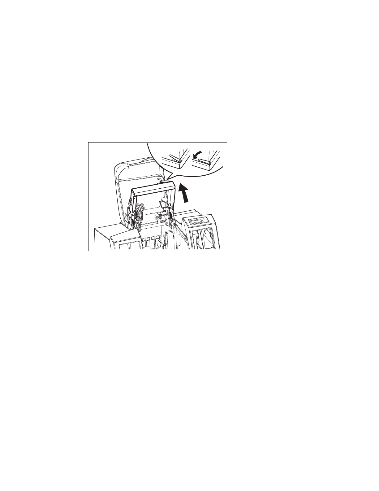
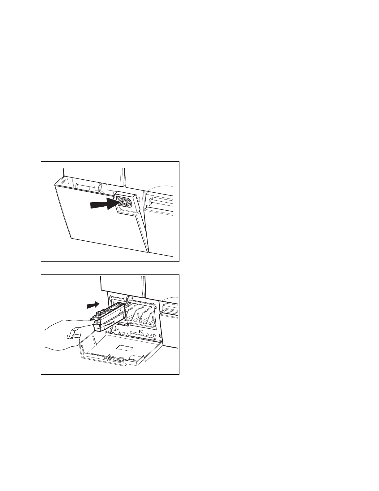
Install printheads
1. Open the top cover of the printer.
The printhead carriage will move to the center of
the printer.
2. Remove the packing tape from each of the
latches on the carriage.
6 SETTING UP THE PRINTER
3. Remove a printhead from its packaging, then
remove the protective cap and tape.
NOTE: Take care not to touch the nozzles of the
printhead.
Keep the protective cap and tape so that you can
replace them on the printhead, if you should ever
need to remove it from the printer.
4. Look at the carriage, which has colored labels
showing where the printhead for each color should
be installed. Release and flip up the latch for the
printhead you are installing.
5. Push the printhead firmly into the carriage.
NOTE: You will not be able to push the printhead
in place if it is in the wrong slot.
6. Flip the latch down over the printhead and
secure it by pressing down.
7. Repeat steps 3 to 6 until all the printheads have
been installed.
8. Close the top cover.
The printer will check and initialize the printheads.
SETTING UP THE PRINTER 7

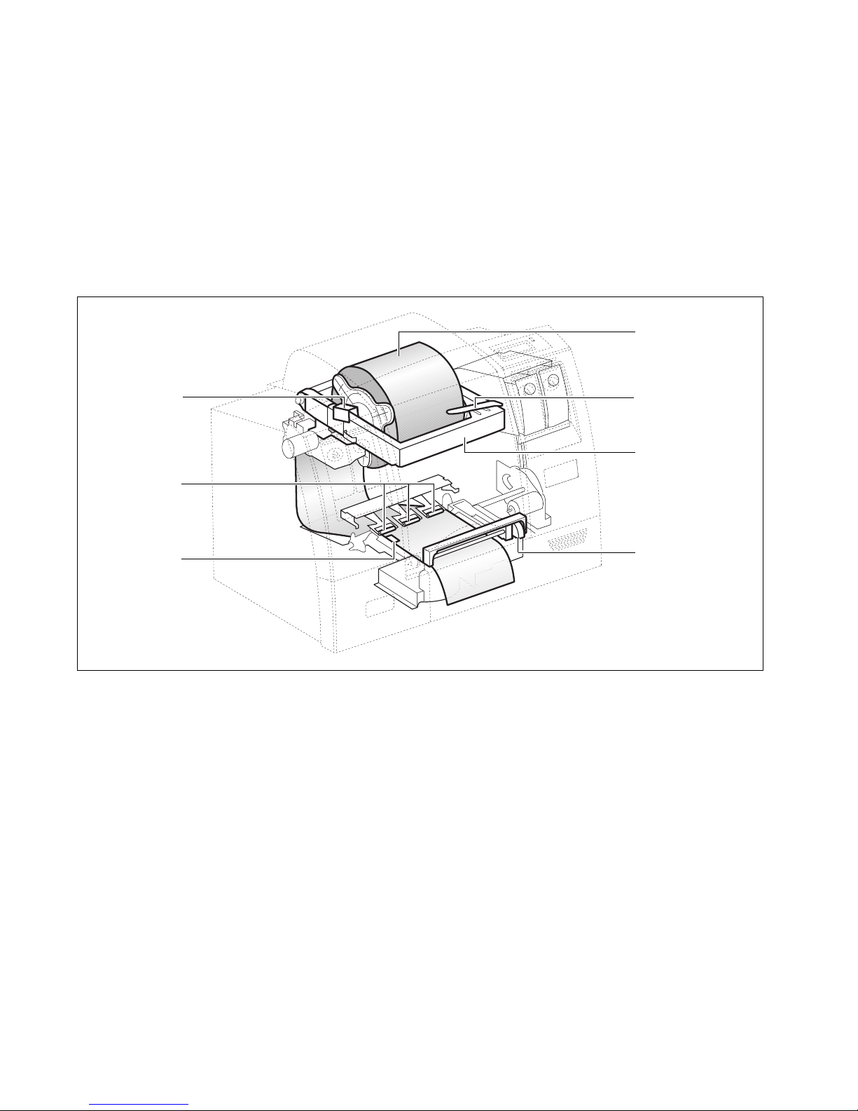
Load continuous media
The following cutaway view shows the path of the media through the printer and
important parts inside the printer.
clamp that locks
spindle in place
(one on each
side of the roll)
pinch rollers
media roll loaded
in spindle
lever to release
frame
frame that supports
media roll
media sensor
manual cutter
Media path through the printer
The first time you set up the printer, load the continuous media provided with
the printer. This media is needed to run the printhead alignment procedure.
1. Open the printer’s top cover.
8 SETTING UP THE PRINTER
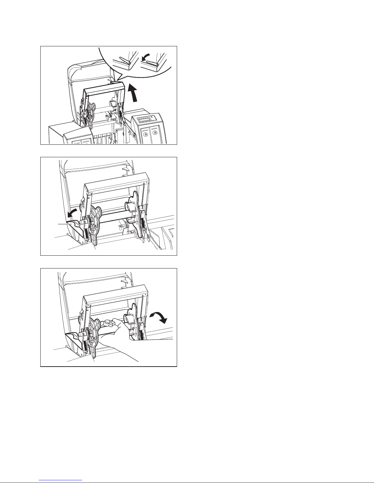
clamp
2. Push and hold the green lever to lift up the
frame that supports the media roll. Make sure you
push the frame up to its highest level so that the
pinch rollers (see the figure on page 8) are raised
above the platen.
3. Push back the clamps (which are marked with
green labels) at both sides of the frame.
4. Remove the spindle from the frame, by lifting it
slightly upwards and towards yourself.
SETTING UP THE PRINTER 9
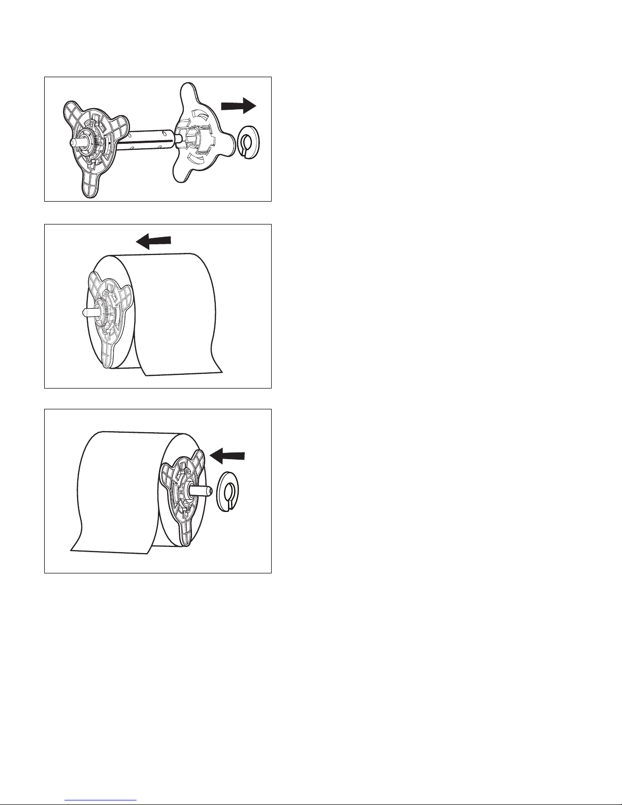
5. Pull the green lock ring and the right side of the
spindle off the central core.
6. Insert the spindle into the roll. The free end of
the roll should hang off the front.
7. Replace the right side of the spindle and push it
against the roll. If you can’t fit it back over the
central core, rotate it slightly so that the notches on
the two parts line up properly. Then replace the
lock ring.
10 SETTING UP THE PRINTER
8. Place the spindle into the frame. The gear of the
spindle should be on the left and the free end of the
roll in front.
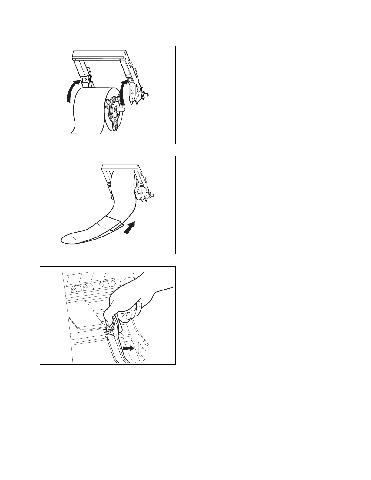
9. Slip the media loading tool over the free end of
the roll. Align the media against the left side of the
tool.
10. Reach inside the printer and push the green
media width guide to the right.
SETTING UP THE PRINTER 11
11. Feed the loading tool through the opening
above the rollers at the back of the printer.
12. Continue feeding the media in until it appears
under the pinch rollers. Make sure the media runs
under the Top-of-Form sensor (on the left, in front
of the pinch rollers).
13. Finally, feed the media through the cutter.
12 SETTING UP THE PRINTER
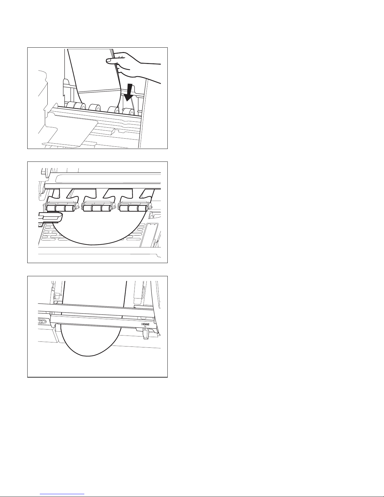
14. Remove the media loading tool.
15. Make sure the edge of the media is lined up
against the red alignment mark on the left.
Check that the media has been fed correctly through the printer (steps 11 to 15) as shown below.
under the
Top-of-Form sensor
against the red
alignment mark
under the pinch rollers
through the manual cutter
SETTING UP THE PRINTER 13
alignment
arrow
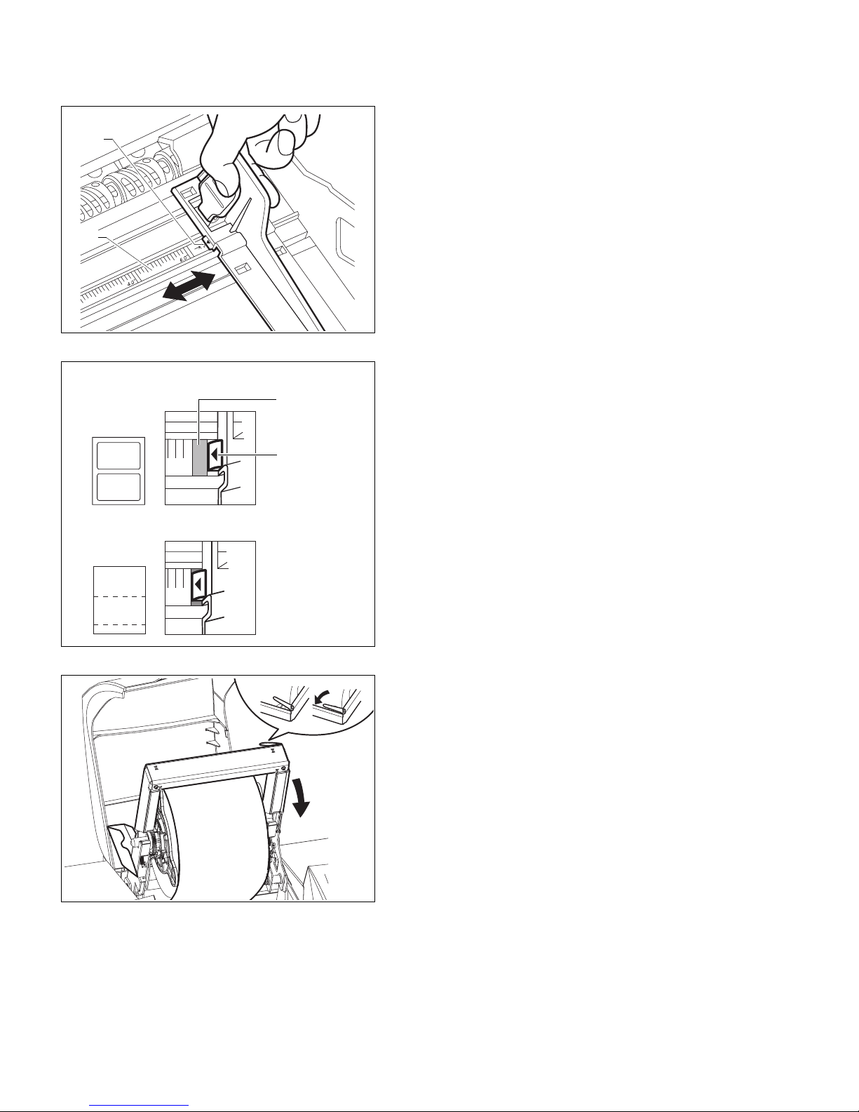
ruler
16. Move the media width guide against the right
edge of the media.
Placement of media width guide
• Pre-cut labels
4.0
• Continuous or tag media
4.0
green band
on ruler
alignment
arrow
green lever
To position the media width guide correctly, you
can make use of the alignment arrow and the green
bands on the ruler.
The diagram on the left illustrates the correct
placement for 4” media:
• For pre-cut labels, the alignment arrow should be
against the right side of the green band at the 4”
mark.
• For continuous media or tag media, the arrow
should be against the left side of the green band at
the 4” mark.
17. Push and hold the green lever to lower the
frame. Be careful when lowering the frame. The
clamps on both sides of the frame will close
automatically.
14 SETTING UP THE PRINTER
18. Close the printer cover.
19. Press the Feed button on the control panel. The
printer will feed the media and correctly position it
for printing.
ONLINE
Feed Menu
The control panel will show that the printer is now
ONLINE.
Run the printhead alignment procedure
The automatic printhead alignment procedure must be performed during
installation and whenever you load new printheads in the printer. This will
ensure that all the printheads line up and maximize print quality. If you do not do
this, your printout can look fuzzy or blurred.
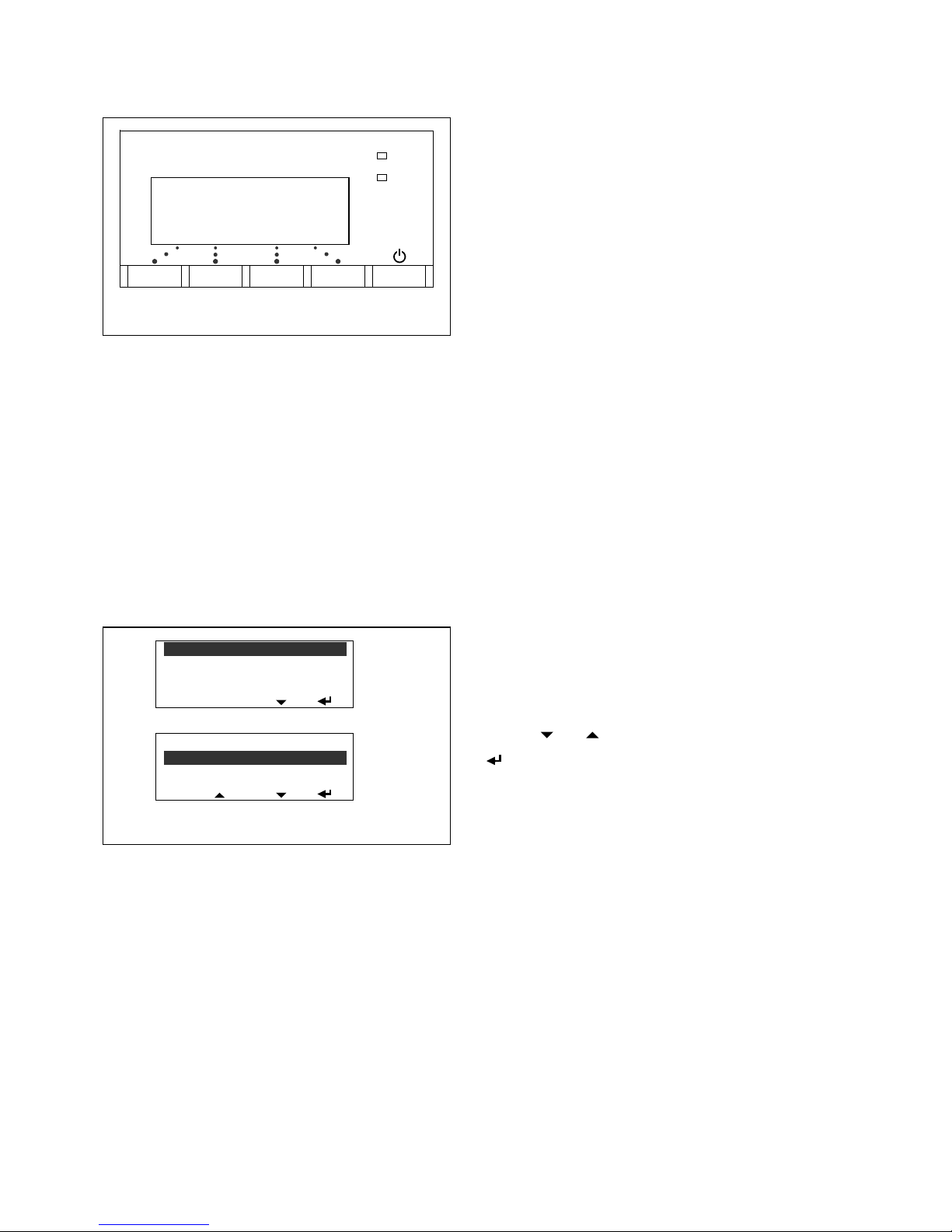
1. On the control panel,
PRINTHEAD MAINTENANCE
CLEAN PRINTHEADS
PRINT STATUS LABEL
esc
– Press the
– Select
– Select
Menu button to enter the main menu.
PRINTHEAD MAINTENANCE.
PRINTHEAD ALIGNMENT.
INSTALL/REPLACE
PRINTHEAD ALIGNMENT
CHECK
esc
Once the printhead alignment procedure is completed, remove the 6” continuous
media roll and load the media you will be working with.
See Load a new media roll on page 24 which describes the additional steps
required when loading new media for printing.
(Press or to move through the options; press
to select an option.)
The alignment procedure will take between 10 and
30 minutes to complete. A message appears on the
control panel when it is completed.
SETTING UP THE PRINTER 15
Connect the printer to a computer
To connect the printer to a single computer, use the USB connector at the back
of the printer.
NOTE: If the computer does not have a USB connector or the operating system
does not support USB, connect the printer using a CAT5 cross-over cable as
described in the next section.
1. Insert the USB cable into the USB connector at the back of the printer.
2. Connect the other end of the USB cable to your computer. When you do so, the
computer will display a message that new hardware has been found. Install the
printer driver from CD-ROM provided with the printer (see page 20).
NOTE: It can take up to five minutes for the computer to recognize the printer.
Please do not proceed with printer installation until the computer has discovered
the printer.
16 SETTING UP THE PRINTER
Connect the printer to a network
To connect the printer to a network, use the 10BaseT Ethernet connector at the
back of the printer. If connecting the printer directly to a single computer, use a
CAT5 cross-over cable.
1. Insert the cable into the Ethernet connector at the back of the printer.
2. Connect the other end of the cable to the Ethernet port on your network hub or
computer.
3. Set up the TCP/IP parameters for the printer. Contact your network
administrator for the required parameters.
Detailed instructions for entering the parameters are given on the following
pages. The procedure depends on whether you are connecting the printer to:
• A single computer. You will have to enter the IP address and subnet mask.
• A network that uses DHCP or BOOTP to automatically allocate an IP
address to the printer.
• A network that requires a fixed IP address for the printer. You will have to
enter the IP address together with the subnet mask, gateway, and DNS.
4.
IMPORTANT: When you complete the network settings, reset the printer by
turning it off and on again. Always use the Power button on the control panel to
turn the printer on or off.
SETTING UP THE PRINTER 17

Enter TCP/IP parameters
The TCP/IP parameters are entered using the printer’s control panel. On the
control panel, press or to scroll through the menus; and press to select
an option.
Connecting to a single computer
1. When giving the printer an IP address, you may have to look at or change the IP
setting of your computer, because the first three sets of digits in the IP address of
the computer and printer must be the same. For example, the computer’s IP
address could be 192.168.188.10 while the printer’s IP address is
192.168.188.20.
2. Set up a fixed IP address:
a. On the control panel, press the
b. Select
c. Select
d. Select
e. Select
The default IP address will be displayed with the cursor under the first digit.
• Press to scroll to the desired value and press to select it.
The cursor will move to the next digit.
• Repeat this step to complete the IP address.
• When done, press again and then press
Menu button to enter the main menu.
INTERFACE.
TCPIP.
MANUAL.
IP ADDR.
esc.
3. Follow the instructions in step 2, but instead of
Set the subnet mask (e.g. 255.255.255.0) but leave the gateway and DNS alone.
Connecting to a network that uses DHCP or BOOTP
1. Specify DHCP or BOOTP:
a. On the control panel, press the
b. Select
c. Select
d. Select
18 SETTING UP THE PRINTER
IP ADDR, select SUBNET MASK.
Menu button to enter the main menu.
INTERFACE.
TCPIP.
DHCP or BOOTP.

Connecting to a network that requires a fixed IP address
1. Set up a fixed IP address (network):
a. On the control panel, press the
b. Select
c. Select
d. Select
e. Select
INTERFACE.
TCPIP.
MANUAL.
IP ADDR.
The default IP address will be displayed with the cursor under the first digit.
• Press to scroll to the desired value and press to select it.
The cursor will move to the next digit.
• Repeat this step to complete the IP address.
• When done, press again and then press
Menu button to enter the main menu.
esc.
2. Follow the instructions in step 1, but instead of
GATEWAY, and DNS in turn and set the values in the same way.
IP ADDR, select SUBNET MASK,
SETTING UP THE PRINTER 19

Install the printer driver
The printer driver works with Windows 98 and above (for detailed requirements,
see page 94). Install the printer driver from the CD-ROM labeled ‘BarTender
Label Printing Software, VIPColor Special Edition’.
1. Insert the CD-ROM into the drive.
2. From the setup screen, select
3. From the next screen, select
Seagull Printer Drivers.
Install Printer Driver.
4. Follow the instructions on the screen to complete the installation. The actual
procedure will depend on your operating system.
20 SETTING UP THE PRINTER

You can also install the BarTender Label Printing Software which lets you
design and print labels using various types of image files (including .bmp, .dxf,
.img, .jpg, .pcx, .dcx, .png, and .tif). You may also use other Windows
applications to design labels and use other types of image files.
NOTE: VIPColor Technologies endeavours to test the driver with multiple
software applications, but does not guarantee its error-free operation, and
disclaims any liability resulting therefrom.
Additional information on installing the printer driver can be found on the
CD-ROM or downloaded from the VIPColor website.
SETTING UP THE PRINTER 21

Set up email warnings (optional)
If you are using an Ethernet connection, the printer can be set up to send out
email messages to selected recipients when problems are encountered, so that
action can be taken.
• An email account must be set up for the printer. You will need to know the
account name and password, as well as the POP3 and SMTP server address.
• Email warnings must be enabled from the printer’s control panel (see step 1
below).
• The printer’s email settings and the recipients are set up from the printer’s
internal web pages (see chapter 4).
1. Enable email warnings from the printer’s control panel:
– Press the
– Select
– Select
– Press (Enter) to enable email warnings.
(Press or to move through the options; press to select an option.)
Menu button to enter the main menu.
INTERFACE.
EMAIL.
2. Log on to the printer’s internal web pages as follows: Enter the printer’s IP
address in your web browser, then enter the user name and password (see
page 51) in the dialog box that appears.
3. From the printer’s home page, select
Setup email warnings.
4. Click on the ‘Set up email properties’ link.
5. Enter the printer’s email account settings and click Apply.
6. Enter the email addresses of the people who will be sent the warning messages.
You can specify up to three recipients.
7. Click Apply to save the settings.
22 SETTING UP THE PRINTER

Chapter 2
Printing on Different Types of Media
The printer supports a variety of label types and shapes, from die-cut labels to
continuous media. For best operation, it is strongly recommended that you use
the specially coated media types listed below.
About color profiles
Differences in the composition and thickness of different types of media require
the printer to handle each type differently. For each media type that the printer
supports, a color profile has been created. This color profile not only defines
how color should be printed, but also various other settings that optimize the
output quality for the media type.
It is therefore important, whenever you load a new type of media in the printer,
that you select the same type in the printer driver. This ensures that the
appropriate color profile is used for printing. If you do not select the correct
media type, the output quality may not be optimal.
New profiles can be downloaded and selected using the printer driver. You can
download up to seven other profiles into the printer at any one time. All internal
pre-programmed profiles support all print modes, while new profiles are made
specifically for the print mode that they will be used with (Fast, Normal, High or
Premium). Depending on the print mode you select in the printer driver, the
printer will either optimize quality or speed.
Color profiles are currently available for the following media types:
• STANDARD MATT LABEL 1
• STANDARD MATT TAG
• STANDARD SEMI GLOSS LABEL
• STANDARD MATT LABEL 1
• STANDARD SYNTHETIC LABEL
• STANDARD GLOSS
PRINTING ON DIFFERENT TYPES OF MEDIA 23
Your label supplier can tell you which profile is best for your media.
Load a new media roll
The following cutaway view shows the path of the media through the printer and
important parts inside the printer.
clamp that locks
spindle in place
(one on each
side of the roll)
pinch rollers
media roll loaded
in spindle
lever to release
frame
frame that supports
media roll
media sensor
manual cutter
Media path through the printer
After loading a new roll of media, always check to see if you need to:
• Set the media selector (page 32)
• Change printer settings (page 32)
24 PRINTING ON DIFFERENT TYPES OF MEDIA
 Loading...