


VIPA System 200V
CPU | Manual
HB97E_CPU | RE_21x-2BM03 | Rev. 14/44
October 2014

Copyright © VIPA GmbH. All Rights Reserved.
This document contains proprietary information of VIPA and is not to be disclosed or used except in accordance with applicable
agreements.
This material is prot ected by the copyright laws. It may not be reproduced, distributed, or al tered in any fashion by any entity (either
internal or external to VIPA), except in ac cordance with applicable agreements, contracts or licensing, without the express written
consent of VIPA and the business management owner of the material.
For permission to reproduce or dis tribute, please contact:
VIPA, Gesellsc haft für Visualisierung und Prozes sautomatisierung mbH
Ohmstraße 4, D-91074 Herzogenaurach, Germany
Tel.: +49 (91 32) 744 -0
Fax.: +49 9132 744 1864
EMail: info@vipa.de
http://www.vipa.com
Note
Every effort has been made to ens ure that the information cont ai ned i n this document was compl ete and accurate at the tim e of
publishing. Nevertheless, the authors retain the right to modify the information. This customer document describes all the hardware units
and functions known at the present t i me. Descriptions may be included for units which are not present at the customer site. The exact
scope of delivery is descri bed i n t he respective purchase contract.
CE Conformity Declaration
Hereby, VIPA GmbH declares that the products and syst ems are in compliance with t he essential requirements and ot her rel evant
provisions.
Conformity is indicated by the CE marking affixed to the product.
Conformity Information
For more information regarding CE marking and Declaration of Conformity (DoC), please contact your l ocal VIPA customer service
organization.
Trademarks
VIPA, SLIO, Sys tem 100V, System 200V, System 300V, Sys t em 300S, System 400V, System 500S and Commander Compact are
registered trademarks of VIPA Gesellschaft f ü r V i sualisierung und Prozessautom atisierung mbH.
SPEED7 is a registered t rademark of profichip GmbH.
SIMATIC, STEP, SINEC, TIA Portal, S7-300 and S7-400 are registered trademarks of Siemens AG.
Microsoft und Wi ndows are registered trademarks of Micros oft Inc., USA.
Portable Document Form at (PDF) and Postscript are regist ered trademarks of Adobe Systems, Inc.
All other trademarks, logos and service or product marks specified herein are owned by their respective companies.
Information product support
Contact your local VIPA Customer Service Organization repres entative if you wish to report errors or questions regarding the contents
of this document. If you are unable to locate a customer service center, contact VIPA as follows:
VIPA GmbH, Ohmstraße 4, 91074 Herzogenaurach, Germany
Telefax:+49 9132 744 1204
EMail: documentation@vipa.de
Technical support
Contact your local VIPA Customer Service Organization repres entative if you encounter problems with the product or have questions
regarding the product. If you are unable to l ocate a customer servic e center, contact VIPA as follows:
VIPA GmbH, Ohmstraße 4, 91074 Herzogenaurach, Germany
Telephone: +49 9132 744 1150 (Hotline)
EMail: support@vipa.de

Manual VIPA System 200V Contents
HB97E - CPU - RE_21x-2BM03 - Rev. 14/44 i
Contents
About this manual....................................................................................1
Safety information.................................................................................... 2
Chapter 1
Basics and Assembly.....................................................1-1
Safety Information for Users.................................................................1-2
System conception...............................................................................1-3
Dimensions..........................................................................................1-5
Installation............................................................................................1-7
Demounting and module exchange....................................................1-11
Wiring................................................................................................. 1-12
Installation gu idelines.........................................................................1-14
General data ...................................................................................... 1-17
Chapter 2 Hardware description......................................................2-1
Properties.............................................................................................2-2
Structure...............................................................................................2-3
Technical Data.....................................................................................2-7
Chapter 3 Deployment CPU 21x-2BM03..........................................3-1
Assembly..............................................................................................3-2
Start-up behavior..................................................................................3-2
Addressing........................................................................................... 3-3
Hints for the deployment of the MPI interface....................................... 3-5
Hardware configuration - CPU..............................................................3-6
Hardware configuration - I/O modules..................................................3-8
Setting CPU parameters.......................................................................3-9
Project trans fe r...................................................................................3-13
Operating modes................................................................................3-17
Overall reset.......................................................................................3-19
Firmware update................................................................................3-21
Factory reset......................................................................................3-23
VIPA specific diagnostic entries..........................................................3-24
Using test functions for control and monitoring of variables................ 3-26
Chapter 4 PROFIBUS communication............................................4-1
Overview..............................................................................................4-2
Project engineering CPU with integrated PROFIBUS DP master .........4-5
PROFIBUS installation guidelines ........................................................4-7
Commissioning and Start-up behavior................................................ 4-10

Contents Manual VIPA System 200V
ii HB97E - CPU - RE_21x-2BM03 - Rev. 14/44

Manual VIPA System 200V About this manual
HB97E - CPU - RE_21x-2BM03 - Rev. 14/44 1
About this manual
This manual describes the System 200V CPU 21x-2BM03
from VIPA. Her e
you may find every information for commissioning and operation.
Chapter 1: Basics and Assembly
The focus of this chapter is on the introduction of the VIPA System 200V.
Here you will find the information req uir ed to assemble and wire a controller
system consisting of System 200V components.
Besides the dimensions the general technical data of System 200V will be
found.
Chapter 2: Hardware description
Here the hardware components of the CPU
are described. The technical
data are at the end of the chapter.
Chapter 3: Deployment CPU 21x-2BM03
This chapter describes the deployment of the CPU in the System 200V.
The description refers directly to the CPU and to the deployment in
connection with peripheral modules, mounted on a profile r ail together with
the CPU at the backplane bus.
Chapter 4: PROFIBUS communication
Content of this chapter is the deployment of the 21x-2BM03 with
PROFIBUS. After a short introduction into the PROFIBUS system, the
project engineering and the usag e with PROFI BUS is shown.
This chapter ends with information about commissioning and start-up
behavior of the DP master.
Overview

About this manual Manual VIPA System 200V
2 HB97E - CPU - RE_21x-2BM03 - Rev. 14/44
This manual describes the System 200V CPU 21x-2BM03 from VI PA.
It contains a description of the construction, project implementation and
usage.
This manual is part of the document at ion package with order number
HB97E_CPU and relevant for:
Product Order number as of state:
CPU-HW CPU-FW DPM-FW
CPU 21xDPM VIPA CPU 21x-2BM03 01 V 4.1.7 V 5.2.2
The manual is targeted at users who have a background in automation
technology.
The manual consists of chapters. Every chapter provides a self-contained
description of a specific topic.
The following guides are available in the manual:
• an overall table of contents at the beginning of the manual
• an overview of the topics for every chapter
The manual is available in:
• printed form, on paper
• in electronic form as PDF-f ile (Adobe Acrobat Reader)
Important passages in the text are highlighted by following icons and
headings:
Danger!
Immediate or likely danger.
Personal injury is possible.
Attention!
Damages to property is likely if t hese warning s ar e not heeded.
Note!
Supplementary information and usef ul t ips.
Objective and
contents
Target audience
Structure of the
manual
Guide to the
document
Availabilit
y
Icons
Headings

Manual VIPA System 200V Safety information
HB97E - CPU - RE_21x-2BM03 - Rev. 14/44 3
Safety information
The CPU 21x is constructed and produced for:
• all VIPA System 200V components
• communication and process control
• general control and automation applications
• industrial applications
• operation within the environmental conditions specified in the technical
data
• installation into a cubicle
Danger!
This device is not certified for applicat ions in
• in explosive environments (EX-zone)
The manual must be available to all personnel in the
• project design department
• installation department
• commissioning
• operation
The following conditions must be met bef ore usi ng or commissioning
the components described in this manual:
• Hardware modifications to the process control system should only be
carried out when the system has been disconnected from power!
• Installation and hardware modifications only by properly trained
personnel.
• The national rules and regulations of the respective country must be
satisfied (installation, safety, EMC ...)
National rules and regulations apply to the disposal of t he uni t !
Applications
conforming with
specifications
Documentation
Disposal

Safety information Manual VIPA System 200V
4 HB97E - CPU - RE_21x-2BM03 - Rev. 14/44

Manual VIPA System 200V Chapter 1 Basics and Assembly
HB97E - CPU - RE_21x-2BM03 - Rev. 14/44 1-1
Chapter 1 Basics and Assembly
The focus of this chapter is on the introduction of the VIPA System 200V.
Here you will find the information req uir ed to assemble and wire a controller
system consisting of System 200V components.
Besides the dimensions the general technical data of System 200V will be
found.
Topic Page
Chapter 1
Basics and Assembly.....................................................1-1
Safety Information for Users................................................................. 1-2
System conception...............................................................................1-3
Dimensions..........................................................................................1-5
Installation............................................................................................1-7
Demounting and module exchange....................................................1-11
Wiring.................................................................................................1-12
Installation gu idelines.........................................................................1-14
General data......................................................................................1-17
Overview
Contents

Chapter 1 Basics and Assembly Manual VIPA System 200V
1-2 HB97E - CPU - RE_21x-2BM03 - Rev. 14/44
Safety Information for Users
VIPA modules make use of highly integrated components in MOSTechnology. These components are extremely sensitive to over-voltages
that can occur during electrostatic discharges.
The following symbol is attached to modules that can be destroyed by
electrostatic discharges.
The Symbol is located on the module, the module rack or on packing
material and it indicates the presence of elect r ostatic sensitive equipment.
It is possible that electrostatic sensitive equipm ent is destr oyed by energies
and voltages that are far less than the human threshold of perception.
These voltages can occur where persons do not discharge themselves
before handling electrostatic sensitive modules and they can damage
components thereby, causing the module to become inoperable or
unusable.
Modules that have been damaged by electrostatic discharges can f ail after
a temperature change, mechanical shock or changes in the electrical load.
Only the consequent implementation of protection devices and meticulous
attention to the applicable rules and regulat ions for handling the respective
equipment can prevent failures of electrostatic sensitive modules.
Modules must be shipped in the original packing mater ial.
When you are conducting measurements on electrostatic sensitive modules
you should take the following precautions:
• Floating instruments must be discharged before use.
• Instruments must be grounded.
Modifying electrostatic sensitive modules you should only use soldering
irons with grounded tips.
Attention!
Personnel and instruments should be grounded when working on
electrostatic sensitive modules.
Handling of
electrostatic
sensitive modules
Shipping of
electrostatic
sensitive modules
Measurements and
alterations on
electrostatic
sensitive modules

Manual VIPA System 200V Chapter 1 Basics and Assembly
HB97E - CPU - RE_21x-2BM03 - Rev. 14/44 1-3
System conception
The System 200V is a modular automation system for assembly on a
35mm profile rail. By means of the peripheral modules with 4, 8 and 16
channels this system may properly be adapted matching to your
automation tasks.
PW
SF
FC
MC
CPU 215
DC
24V
+
-
1
2
RN
ST
MR
X1
MMC
R
S
X2
34
VIPA 215-1BA03
M
P
I
2
DI 8xDC24V
SM 221
.0
.1
.2
.3
.4
.5
.6
.7
VIPA 221-1BF00
X2
34
1
2
3
4
5
6
7
8
9
I0
DI 8xDC24V
SM 221
.0
.1
.2
.3
.4
.5
.6
.7
VIPA 221-1BF00
X2
34
1
2
3
4
5
6
7
8
9
I0
DI 8xDC24V
SM 221
.0
.1
.2
.3
.4
.5
.6
.7
VIPA 221-1BF00
X2
34
1
2
3
4
5
6
7
8
9
I0
DI 8xDC24V
SM 221
.0
.1
.2
.3
.4
.5
.6
.7
VIPA 221-1BF00
X2
34
1
2
3
4
5
6
7
8
9
I0
The System 200V consists of the following components:
• Head modules like CPU and bus coupler
• Periphery modules like I/O, function und communication modules
• Power supplies
• Extension modules
CPU 214
M
P
I
PW
SF
FC
MC
R
S
RN
ST
MR
MMC
2
1
2
-
DC
24V
+
X1
VIPA 214-1BC03
X2
34
PW
ER
RD
DE
IM 253DP
ADR.
X8
910
VIPA 253-1DP00
+
-
1
2
DC
24V
X1
D
P
99
With a head module CPU r espectively bus
interface and DC 24V power supply are
integrated to one casing.
Via the integrated power supply the CPU
respectively bus interface is power
supplied as well as the electronic of the
connected periphery modules.
.0
.1
.2
.3
.4
.5
.6
.7
.0
.1
.2
.3
.4
.5
.6
.7
1
2
3
4
5
6
7
8
9
10
11
12
13
14
15
16
17
18
VIPA 221-1BH10
X2
3
4
DI 16xDC24V
n+1
n
DI 8xAC/..48V
SM 221
.0
.1
.2
.3
.4
.5
.6
.7
N
VIPA 221-1FF30
X2
3
4
1
2
3
4
5
6
7
8
9
I0
1
2
3
4
5
6
7
8
9
10
The modules are direct installed on a
35mm profile rail and connected to the
head module by a bus connector, which
was mounted on the profile rail before.
Most of the periphery modules are
equipped with a 10pin respectively 18pin
connector. This connector provides the
electrical interface for the signaling and
supplies lines of the modules.
Overview
Components
Head modules
Periphery modules

Chapter 1 Basics and Assembly Manual VIPA System 200V
1-4 HB97E - CPU - RE_21x-2BM03 - Rev. 14/44
PS 207/2
X2
34
VIPA 207-1BA00
L
N
P
E
100-240V AC
550-230mA
50-60Hz
OH
OL
OK
X1
1
2
3
4
+
-
+
-
OUT DC 24V /
∑Ι:
2A
4A (peak)
G
DC 24V
DC 24V
With t he System 200V the DC 24V power
supply can take place either externally or
via a particularly for this developed power
supply.
The power supply may be mounted on the
profile rail together with the System 200V
modules. It has no connector to the back plane bus.
CM 201
VIPA 201-1AA00
X2
34
X2.X1.
The expansion modules are complementary modules providing 2- or 3wire connection facilities.
The modules are not connected to the
backplane bus.
• Profile rail 35mm
• Dimensions of the basic enclosure:
1tier width: (HxWxD) in mm: 76x25.4x74 in inches: 3x1x3
2tier width: (HxWxD) in mm: 76x50.8x74 in inches: 3x2x3
Please note that you can only install header modules, like the CPU, t he PC
and couplers at slot 1 or 1 and 2 (for double width modules).
[1] Head module
(double width)
[2] Head module
(single width)
[3] Periphery module
[4] Guide rails
1
2
4
3
0
1
Clack
D
P
Note
A maximum of 32 modules can
be connected at the back plane
bus. Take attention that here the
maximum sum current of 3.5A
is not exceeded.
Please install modules with a
high current consumption direct ly beside the header module.
Power supplies
Expansion
modules
Structure/
dimensions
Installation

Manual VIPA System 200V Chapter 1 Basics and Assembly
HB97E - CPU - RE_21x-2BM03 - Rev. 14/44 1-5
Dimensions
1tier width (HxWxD) in mm: 76 x 25.4 x 74
2tier width (HxWxD) in mm: 76 x 50.8 x 74
80 mm
60 mm
74 mm
88 mm
ca. 110 mm
84 mm
85 mm
76,62 mm
76 mm
2,77 cm
24 mm
Dimensions
Basic enclosure
Installation
dimensions
Installed and wired
dimensions
In- / Output
modules

Chapter 1 Basics and Assembly Manual VIPA System 200V
1-6 HB97E - CPU - RE_21x-2BM03 - Rev. 14/44
84,46 mm
88 mm
4,66 mm
27 mm
8 cm
76 mm
24 mm
11 mm
85 mm
89 mm
89 mm
27 mm
8 cm
76 mm
12 cm
125 mm
91 mm
65 mm
24 mm
5 mm
11 mm
85 mm
Function modules/
Extension modules
CPUs (here with
EasyConn from
VIPA)

Manual VIPA System 200V Chapter 1 Basics and Assembly
HB97E - CPU - RE_21x-2BM03 - Rev. 14/44 1-7
Installation
The modules are each installed on a 35mm profile rail and connected via a
bus connector. Before installing the module the bus connector is to be
placed on the profile rail before.
For installation the following 35mm profile rails may be used:
35 mm
27 mm
15 mm
1,5 mm
35 mm
27 mm
7,5 mm
1 mm
Order number Label Description
290-1AF00 35mm profile rail Length 2000mm, height 15mm
290-1AF30 35mm profile rail Length 530mm, height 15m m
System 200V modules communicate via a backplane bus connector. T he
backplane bus connector is isolated and available from VIPA in of 1-, 2-, 4or 8tier width.
The following figure shows a 1tier connector and a 4t ier connector bus:
The bus connector is to be placed on the profile r ail until it clips in its place
and the bus connections look out from t he pr ofile rail.
Order number Label Description
290-0AA10 Bus connector 1tier
290-0AA20 Bus connector 2tier
290-0AA40 Bus connector 4tier
290-0AA80 Bus connector 8tier
General
Profile rail
Bus connector

Chapter 1 Basics and Assembly Manual VIPA System 200V
1-8 HB97E - CPU - RE_21x-2BM03 - Rev. 14/44
The following figure shows the installation of a 4tier width bus connector in
a profile rail and the slots for the modules.
The different slot s ar e defined by guide rails.
[1] Header module
(double width)
[2] Header module
(single width)
[3] Peripheral module
PW
ER
RD
BA
ADR.
DC24V
+
-
1
2
0
1
1
2
4
3
PW
SF
FC
MC
MMC
R
S
[4] Guide rails
• Use bus connectors as long as possible.
• Sort the modules with a high current consumption right beside the
header module. In the service area of www.vipa.com a list of current
consumption of every System 200V module can be found.
Installation on a
profile rail
Assembly regarding
the current
consumption

Manual VIPA System 200V Chapter 1 Basics and Assembly
HB97E - CPU - RE_21x-2BM03 - Rev. 14/44 1-9
hoizontal assembly
lying assembly
vertical
assembly
01
0
1
Please regard the allowed environmental temperatures:
• horizontal assembly: from 0 to 60°C
• vertical assembly: from 0 to 40°C
• lying assembly: from 0 to 40°C
The horizontal assembly always starts at the lef t side with
a header module, then you install the peripheral modules
beside to the right.
You may install up to 32 peripheral modules.
80 mm
60 mm
Please follow these rules during the assembly!
• Turn off the power supply befor e you install or remove
any modules!
• Make sure that a clearance of at least 60mm exists
above and 80mm below the middle of the profile rail.
• Every row must be completed from left to right and it
has to start with a header module.
[1] Header module (double width)
[2] Header module (single width)
12
4
3
[3] Peripheral modules
[4] Guide rails
• Modules are to be installed side by side. Gaps are not
permitted between the modules since this would
interrupt the backplane bus.
• A module is only installed properly and connected
electrically when it has clicked into place with an
audible click.
• Slots after the last module may rem ain unoccupied.
Note!
A maximum of 32 modules can be connected at the back plane bus. Tak e
attention that here the maximum sum current of 3.5A is not exceeded.
Assembly
possibilities

Chapter 1 Basics and Assembly Manual VIPA System 200V
1-10 HB97E - CPU - RE_21x-2BM03 - Rev. 14/44
• Install the profile rail. Make sure that a clearance of at least 60mm
exists above and 80mm below the middle of the profile rail.
• Press the bus connector into the profile rail until it clips securely into
place and the bus-connectors look out from the profile rail. This
provides the basis for the installation of your m odules.
• Start at the outer left location with the installation of your header
module and install the peripheral modules to the rig h t of this.
[1] Header module
(double width)
[2] Header module
(single width)
[3] Peripheral module
12
4
3
[4] Guide rails
• Insert the module that you are installing into t he profile rail at an angle
of 45 degrees f rom the top and rotate the module into place until it
clicks into the prof ile rail with an audible click. The proper connect ion
to the backplane bus can only be guaranteed when the module has
properly clicked into place.
Clack
Attention!
Power must be turned off before modules are
installed or removed!
Assembly
procedure

Manual VIPA System 200V Chapter 1 Basics and Assembly
HB97E - CPU - RE_21x-2BM03 - Rev. 14/44 1-11
Demounting and module exchange
1
2
3
4
5
• Remove if exists the wiring to the module, by pressing both
locking lever on the connector and pulling the connect or .
• The casing of the module has a spring loaded clip at the
bottom by which the module can be removed.
• The clip is unlocked by pressing the screwdriver in an upward
direction.
• Withdraw the module with a slight r otation to the top.
Attention!
Power must be turned off before modules are installed or
removed!
Please regard that t he backplane bus is interrupted at the point
where the module was removed!

Chapter 1 Basics and Assembly Manual VIPA System 200V
1-12 HB97E - CPU - RE_21x-2BM03 - Rev. 14/44
Wiring
Most peripheral modules are equipped with a 10pole or a 18pole connector.
This connector provides the electrical interf ace for the signaling and supply
lines of the modules.
The modules carry spring-clip connectors for interconnections and wiring.
The spring-clip connector technolog y simplifies the wiring requirements for
signaling and power cables.
In contrast to screw terminal connections, spring-clip wiring is vibration
proof. The assignment of the terminals is contained in the description of the
respective modules.
You may connect conductors with a diameter from 0.08mm
2
up to 2.5mm2
(max. 1.5mm
2
for 18pole connectors).
The following figure shows a module with a 10pole connector.
1
2
3
4
5
6
7
8
9
10
1
2
3
3 4 5
1
1
1
2
3
4
5
6
7
8
9
10
2
[1]
[2]
[3]
[4]
[5]
Locking lever
Pin no. at the module
Pin no. at the connector
Wiring port
Opening for screwdriver
Note!
The spring-clip is destroyed if you push the screwdriver into the wire port!
Make sure that you only insert the screwdriver into the square hole of t he
connector!
Overview

Manual VIPA System 200V Chapter 1 Basics and Assembly
HB97E - CPU - RE_21x-2BM03 - Rev. 14/44 1-13
• Install the connector on the module unt il it locks with an audible click.
For this purpose you press the two clips together as shown.
The connector is now in a permanent position and can easily be wired.
The following section shows the wiring procedure from top view.
• Insert a screwdriver at an angel into the square opening as shown.
• Press and hold the screwdriver in the opposite direction to open the
contact spring.
• Insert the stripped end of the wire into the r ound opening. You can use
wires with a diameter of 0.08mm
2
to 2.5mm2
(1.5mm
2
for 18pole connectors).
• By removing the screwdriver the wire is connected safely with the plug
connector via a spring.
Note!
Wire the power supply connections first followed by the signal cables
(inputs and outputs).
Wiring procedure

Chapter 1 Basics and Assembly Manual VIPA System 200V
1-14 HB97E - CPU - RE_21x-2BM03 - Rev. 14/44
Installation guidelines
The installation guidelines contain information about the interference free
deployment of System 200V systems. There is the descript ion of the ways,
interference may occur in your control, how you can make sure the
electromagnetic digestibility (EMC), and how you manage the isolat ion.
Electromagnetic digestibilit y (EMC) means the ability of an electrical device,
to function error free in an electromagnetic environment without being
interferenced res. without interferencing the environment.
All System 200V components are developed for the deployment in hard
industrial environments and fulfill hig h demands on the EMC. Nevertheless
you should project an EMC planning before installing the components and
take conceivable interference causes into account.
Electromagnetic interf erences may interfere your control via diff er ent ways:
• Electromagnetic fields (RF coupling )
• Magnetic fields with power frequency
• I/O signal conductors
• Bus system
• Current supply
• Protected earth conductor
Depending on the spreading medium (lead bound or lead free) and the
distance to the interference cause, interferences to your control occur by
means of different coupling mechanisms.
One differs:
• galvanic coupling
• capacitive coupling
• inductive coupling
• radiant coupling
General
What means EMC?
Possible
interference
causes

Manual VIPA System 200V Chapter 1 Basics and Assembly
HB97E - CPU - RE_21x-2BM03 - Rev. 14/44 1-15
In the most times it is enough to take care of some elementary rules to
guarantee the EMC. Please regard the f ollowing basic rules when installing
your PLC.
• Take care of a correct area-wide grounding of the inactive metal parts
when installing your components.
- Install a central connection between the ground and the protected
earth conductor system.
- Connect all inactive metal extensive and impedance-low.
- Please try not to use aluminum parts. Aluminum is easily oxidizing
and is therefore less suitable for grounding.
• When cabling, t ake care of the correct line rout ing.
- Organize your cabling in line groups (high voltage, current supply,
signal and data lines).
- Always lay your high voltage lines and signal res. data lines in
separate channels or bundles.
- Route the signal and data lines as near as possible beside ground
areas (e.g. suspension bars, metal r ails, tin cabinet).
• Proof the correct f ixing of the lead isolation.
- Data lines must be laid isolated (for details see below).
- Analog lines must be laid isolated. When transmitting signals with
small amplitudes the one sided laying of the isolation may be
favorable.
- Lay the line isolation extensively on an isolation/protected earth con-
ductor rail directly after the cabinet entry and fix the isolation with
cable clamps.
- Make sure that the isolation/protected earth conductor rail is
connected impedance-low with the cabinet.
- Use metallic or metalized plug cases for isolated data lines.
• In special use cases you should appoint special EMC actions.
- W ire all inductivities with erase links, which are not addr essed by the
System SLIO modules.
- For lightening cabinets you should avoid luminescent lamps.
• Create a homogeneous reference potential and ground all electrical
operating supplies when possible.
- Please take care for the targeted employment of the grounding
actions. The grounding of the PLC is a protection and functionality
activity.
- Connect installation parts and cabinets with the System SLIO in star
topology with the isolation/protected earth conductor system . So you
avoid ground loops.
- If potential dif ferences between installation parts and cabinets occur,
lay sufficiently dimensioned potential compensation lines.
Basic rules for
EMC

Chapter 1 Basics and Assembly Manual VIPA System 200V
1-16 HB97E - CPU - RE_21x-2BM03 - Rev. 14/44
Electrical, magnetically and electromagnetic interference fields are
weakened by means of an isolation, one talks of absor pt ion.
Via the isolation rail, that is connected conductive with the rack,
interference currents are shunt via cable isolation to the ground. Hereby
you have to make sure, that the connection to the protected earth conductor is impedance-low, because otherwise the interference currents may
appear as interference cause.
When isolating cables you have to reg a r d t he following:
• If possible, use only cables with isolation tangle.
• The hiding power of the isolation should be higher than 80%.
• Normally you should always lay the isolation of cables on both sides.
Only by means of the both-sided connection of the isolation you achieve
high quality interference suppression in the higher frequency area.
Only as exception you may also lay the isolation one-sided. Then you
only achieve the absorption of the lower frequencies. A one-sided
isolation connection may be convenient, if:
- the conduction of a potential compensating line is not possible
- analog signals (some mV res. µA) are transferred
- foil isolations (static isolations) are used.
• With data lines always use metallic or metalized plugs for serial
couplings. Fix the isolation of the data line at the plug rack. Do not lay
the isolation on the PIN 1 of the plug bar !
• At stationary operation it is convenient to strip the insulated cable
interruption free and lay it on the isolation/protected earth conductor line.
• To fix the isolation tangles use cable clamps out of metal. The clamps
must clasp the isolation extensively and have well contact.
• Lay the isolation on an isolation rail directly after the ent ry of the cable in
the cabinet. Lead the isolation further on to the System 200V module
and don't lay it on there again!
Please regard at installation!
At potential differences between the grounding points, there may be a
compensation current via the isolation connected at both sides.
Remedy: Potential compensation line.
Isolation of
conductors

Manual VIPA System 200V Chapter 1 Basics and Assembly
HB97E - CPU - RE_21x-2BM03 - Rev. 14/44 1-17
General data
• Profile rail 35mm
• Peripheral modules with recessed labelling
• Dimensions of the basic enclosure:
1tier width: (HxWxD) in mm: 76x25.4x74 in inches: 3x1x3
2tier width: (HxWxD) in mm: 76x50.8x74 in inches: 3x2x3
• Wiring by means of spring pressure connections (CageClamps) at the
front-facing connector, core cross-section 0.08 ... 2.5mm
2
or 1.5mm2
(18pole plug)
• Complete isolation of the wiring when modules are exchanged
• Every module is isolated from the backplane bus
Structure/
dimensions
Reliabilit
y

Chapter 1 Basics and Assembly Manual VIPA System 200V
1-18 HB97E - CPU - RE_21x-2BM03 - Rev. 14/44
Conformity and approval
Conformity
CE 2006/95/EC Low-voltage directive
2004/108/EC EMC directive
Approval
UL UL 508 Approval for USA and Canada
others
RoHS 2011/65/EU Product is lead-free; Restriction of the use of
certain hazardous substances in electrical and
electronic equipment
Protection of persons and device protection
Type of protection - IP20
Electrical isolation
to the field bus - electrically isolated
to the process level - electrically isolated
Insulation resistance EN 61131-2 Insulation voltage to reference earth
Inputs / outputs - AC / DC 50V, test voltage AC 500V
Protective measures - against short circuit
Environmental conditions to EN 61131-2
Climatic
Storage / transport EN 60068-2-14 -25…+70°C
Operation
Horizontal installation EN 61131-2 0…+60°C
Vertical installation EN 61131-2 0…+60°C
Air humidity EN 60068-2-30 RH1 (without condensation, rel. humidity 10…95%)
Pollution EN 61131-2 Degree of pollution 2
Mechanical
Oscillation EN 60068-2-6 1g, 9Hz ... 150Hz
Shock EN 60068-2-27 15g, 11ms
Mounting conditions
Mounting place - In the control cabinet
Mounting position - Horizontal and vertical
EMC Standard Comment
Emitted
interference
EN 61000-6-4 Class A (Industrial area)
EN 61000-6-2 Industrial area
EN 61000-4-2 ESD
8kV at air discharge (degree of severity 3),
4kV at contact discharge (degree of severity 2)
EN 61000-4-3 HF field immunity (casing)
80MHz … 1000MHz, 10V/m, 80% AM (1kHz)
1.4GHz ... 2.0GHz, 3V/m, 80% AM (1kHz)
2GHz ... 2.7GHz, 1V/m, 80% AM (1kHz)
EN 61000-4-6 HF conducted
150kHz … 80MHz, 10V, 80% AM (1kHz)
EN 61000-4-4 Burst, degree of severity 3
Noise immunity
zone B
EN 61000-4-5 Surge, installation class 3 *
)
*) Due to the high-energetic single pulses with Surge an appropriate external protective circuit with
lightning protection elements like conductors for lightning and overvoltage is necessary.
General data

Manual VIPA System 200V Chapter 2 Hardware description
HB97E - CPU - RE_21x-2BM03 - Rev. 14/44 2-1
Chapter 2 Hardware description
Here the hardware components of the CPU
are described. The technical
data are at the end of the chapter.
Topic Page
Chapter 2
Hardware description......................................................2-1
Properties.............................................................................................2-2
Structure ..............................................................................................2-3
Technical data......................................................................................2-7
Overview
Contents

Chapter 2 Hardware description Manual VIPA System 200V
2-2 HB97E - CPU - RE_21x-2BM03 - Rev. 14/44
Properties
• Instruction set compatible with Siemens STEP
7
• Configuration by means of t he Siem ens SIMATIC manager
• Integrated V-Bus controller for controlling System 200V peripherals
• Integrated 24V power supply
• Total address range: 1024Byte inputs, 1024Byte output s
(128Byte process image each)
• 96 / 128kByte of work memory "on board"
• 144 / 192kByte of load memory "on board"
• MMC slot (for user program)
• Battery backed clock
• MP
2
I interface for dat a t r ansfer
• Status LEDs for operating m ode and diagnostics
• Integrated PROFIBUS DP master
PW
SF
FC
MC
CPU 214DPM
DC
24V
+
-
1
2
RN
ST
MR
X1
MMC
R
S
X2
34
VIPA 214-2BM03
M
P
I
2
RN
IF
DE
ER
D
P
PW
SF
FC
MC
CPU 215DPM
DC
24V
+
-
1
2
RN
ST
MR
X1
MMC
R
S
X2
34
VIPA 215-2BM03
M
P
I
2
RN
IF
DE
ER
D
P
Type Order number Description
CPU 214DPM VIPA 214-2BM03 SPS CPU 214 with PROFIBUS master
and 96/144kByte of work/load memory
CPU 215DPM VIPA 215-2BM03 SPS CPU 214 with PROFIBUS master
and 128/192kByte of work/load memory
CPU 21x-2BM03
Order data

Manual VIPA System 200V Chapter 2 Hardware description
HB97E - CPU - RE_21x-2BM03 - Rev. 14/44 2-3
Structure
[1] Operating mode switch
[2] LEDs of the CPU
[3] Slot for MMC
memory card
[4] MP
2
I interface
[5] Slot for 24V DC
power supply
[6] LEDs of the PROFIBUS
DP master
[7] PROFIBUS DP interface
Front view
CPU 21xDPM
PW
SF
FC
MC
CPU 21xDPM
DC
24V
+
-
1
2
RN
ST
MR
X1
MMC
4
5
3
1
R
S
X2
34
VIPA 21x-2BM03
6
7
M
P
I
2
RN
IF
DE
ER
D
P
2
MP I
2
5
4
3
2
1
9
8
7
6
reserved
M24V
RxD/TxD-P (line B)
RTS
M5V
P5V
P24V
RxD/TxD-N (line A)
n.c.
1
2
3
4
5
6
7
8
9
1
2
+ DC 24 V
0 V
+
-
X1
DP
master
5
4
3
2
1
9
8
7
6
shield
n. c.
RxD/TxD-P (line B)
RTS
M5V
P5V
n. c.
RxD/TxD-N (line A)
n.c.
1
2
3
4
5
6
7
8
9
Interfaces

Chapter 2 Hardware description Manual VIPA System 200V
2-4 HB97E - CPU - RE_21x-2BM03 - Rev. 14/44
The CPU has an internal power supply. This is connected to an external
supply voltage via two terminals located on the front of t he unit .
The power supply requires DC 24V (20.4 ... 28.8V). In addition to the
electronic circuitry of the CPU this supply voltage is used for the modules
connected to the backplane bus.
The electronic circuitry of the CPU is not dc-insulated from the supply
voltage. The power supply is protected against r everse polarity and short
circuits.
Note!
Please ensure that the polarity of the supply voltage is corr ect.
The MPI unit provides the link for the data t ransfer between the CPU and
the PC. Via bus communication you are able to exchange programs and
data between different CPUs that are linked over MPI.
For a serial exchange between the partners you normally need a special
MPI-converter. But now you are also able to use the VIPA "Green Cable"
(Order-No. VIPA 950-0KB00), which allows you to establish a serial peerto-peer connection over the MPI interface.
Please regard the "Hints f or the deployment of the MPI interface" in chapter
"Deployment CPU 21x".
The CPU is connected to the PROFIBUS system by means of a 9pin jack.
Note!
More information about PROFIBUS can be found in the chapter
"PROFIBUS communication".
Power suppl
y
MP
2
I interface
PROFIBUS
interface

Manual VIPA System 200V Chapter 2 Hardware description
HB97E - CPU - RE_21x-2BM03 - Rev. 14/44 2-5
The CPUs have an integrated work and a load m emory. The m emories are
battery-buffered.
Order number Work memory Load memory
VIPA 214-2BM03 96kByte 144kByte
VIPA 215-2BM03 128kByte 192kByte
In the load memory there are program code and blocks stored together with
the header information.
The program parts and block s, which are relevant for t he running program,
are loaded to the work memory during the program sequence.
RN
ST
MR
With the oper ating mode switch you may switch the CPU between STOP
and RUN.
During the transition f rom STOP t o RUN the operating m ode START-UP is
driven by the CPU.
By Switching to MR (Memory Reset) you request an overall reset with
following load from MMC, if a project t her e exists.
You may install a VIPA MMC memory card in this slot as external storage
device (Order No.: VIPA 953-0KX10).
The access to the MMC takes always place after an overall reset.
A rechargeable battery is installed on every CPU 21x to safeguard the
contents of the RAM when power is removed. This battery is also used to
buffer the internal clock.
The rechargeable batt ery is maintained by a charging circuit that receives
its power from the internal power supply and that maintain the clock and
RAM for a max. period of 30 days.
Attention!
Due to a long storage of the CPU, the battery may be discharged
excessively. Please connect the CPU at least for 24 hours to the power
supply, to achieve the full buffer capacit y.
After a power reset and with an empty battery the CPU starts with a BAT
error and executes an overall reset, because with an empty battery the
RAM content is undefined.
Memory
management
Operating mode
switch
MMC slot
memory card
Battery backup for
clock and RAM

Chapter 2 Hardware description Manual VIPA System 200V
2-6 HB97E - CPU - RE_21x-2BM03 - Rev. 14/44
The CPU has got LEDs on its f ront side. In the f ollowing the usage and t he
according colors of the LEDs is described.
Name Color Description
PW green Indicates CPU power on.
R green CPU status is RUN.
S yellow CPU status is STOP.
SF red Is turned on if a system error is detected
(hardware defect)
FC yellow Is turned on when variables are forced (fixed).
MC yellow This LED blinks when the MMC is accessed.
The LEDs are located in the left half of the front panel and they are used for
diagnostic purposes.
The following table shows the color and the signif icance of these LEDs.
Name Color Description
RN green DP-Master-RUN
On: Master status is RUN. The slaves are being
accessed and the outputs are 0 ("clear" state).
On with DE: Master status is "operate". and is
communicating with the slaves.
IF red Initialization error
On: Error in PROFIBUS configuration
DE yellow DE (Data exchange)
On: Indicates PROFIBUS communication activity.
ER red Error
On: Slave has failed
LEDs CPU
LEDs PROFIBUS
DP master

Manual VIPA System 200V Chapter 2 Hardware description
HB97E - CPU - RE_21x-2BM03 - Rev. 14/44 2-7
Technical data
Order no. 214-2BM03
Type CPU 214DPM
Technical data power supply
Power supply (rated value) DC 24 V
Power supply (permitted range) DC 20.4...28.8 V
Reverse polarity protection
9
Current consumption (no-load operation) 130 mA
Current consumption (rated value) 1.5 A
Inrush current 65 A
I²t 0.75 A²s
Max. current drain at backplane bus 3 A
Power loss 5 W
Load and working memory
Load memory, integrated 144 KB
Load memory, maximum 144 KB
Work memory, integrated 96 KB
Work memory, maximal 96 KB
Memory divided in 50% program / 50% data Memory card slot MMC-Card with max. 512 MB
Hardware configuration
Racks, max. 4
Modules per rack, max. total max. 32
Number of integrated DP master 1
Number of DP master via CP 8
Operable function modules 32
Operable communication modules PtP 32
Operable communication modules LAN -
Command processing times
Bit instructions, min. 0.18 µs
Word instruction, min. 0.78 µs
Double integer arithmetic, min. 1.8 µs
Floating-point arithmetic, min. 40 µs
Timers/Counters and their retentive
characteristics
Number of S7 counters 256
S7 counter remanence adjustable 0 up to 64
S7 counter remanence adjustable C0 .. C7
Number of S7 times 256
S7 times remanence adjustable 0 up to 128
S7 times remanence adjustable not retentive
Data range and retentive characteristic
Number of flags 8192 Bit
Bit memories retentive characteristic adjustable adjustable 0 up to 256
Bit memories retentive characteristic preset MB0 .. MB15
Number of data blocks 2047
Max. data blocks size 16 KB
Number range DBs 1 ... 2047
Max. local data size per execution level 1024 Byte
Max. local data size per block 1024 Byte
Blocks
Number of OBs 14
Maximum OB s ize 16 KB
Total number DBs, FBs, FCs Number of FBs 1024
Maximum FB size 16 KB
Number range FBs 0 ... 1023
214-2BM03

Chapter 2 Hardware description Manual VIPA System 200V
2-8 HB97E - CPU - RE_21x-2BM03 - Rev. 14/44
Order no. 214-2BM03
Number of FCs 1024
Maximum FC size 16 KB
Number range FCs 0 ... 1023
Maximum nesting depth per priority class 8
Maximum nesting depth additional within an error OB 1
Time
Real-time clock buffered
9
Clock buffered period (min.) 30 d
Type of buffering Vanadium Rechargeable
Lithium Batterie
Load time for 50% buffering period 20 h
Load time for 100% buffering period 48 h
Accuracy (max. deviation per day) 10 s
Number of operating hours counter 8
Clock synchronization Synchronization via MPI Synchronization via Ethernet (NTP) -
Address areas (I/O)
Input I/O address area 1024 Byte
Output I/O address area 1024 Byte
Process image adjustable Input process image preset 128 Byte
Output process image preset 128 Byte
Input process image maximal 128 Byte
Output process image maximal 128 Byte
Digital inputs 8192
Digital outputs 8192
Digital inputs central 512
Digital outputs central 512
Integrated digital inputs Integrated digital outputs Analog inputs 512
Analog outputs 512
Analog inputs, central 128
Analog outputs, central 128
Integrated analog inputs Integrated analog outputs -
Communication functions
PG/OP channel
9
Global data communication
9
Number of GD circuits, max. 4
Size of GD packets, max. 22 Byte
S7 basic communication
9
S7 basic communication, user data per job 76 Byte
S7 communication
9
S7 communication as server
9
S7 communication as client S7 communication, user data per job 160 Byte
Number of connections, max. 16
Functionality Sub-D interfaces
Type MP²I
Type of interface RS485
Connector Sub-D, 9-pin, female
Electrically isolated MPI
9
MP²I (MPI/RS232)
9
DP master DP slave Point-to-point interface -

Manual VIPA System 200V Chapter 2 Hardware description
HB97E - CPU - RE_21x-2BM03 - Rev. 14/44 2-9
Order no. 214-2BM03
Type DP
Type of interface RS485
Connector Sub-D, 9-pin, female
Electrically isolated
9
MPI MP²I (MPI/RS232) DP master yes
DP slave Point-to-point interface -
Functionality MPI
Number of connections, max. 16
PG/OP channel
9
Routing Global data communication
9
S7 basic communication
9
S7 communication
9
S7 communication as server
9
S7 communication as client Transmission speed, min. 19.2 kbit/s
Transmission speed, max. 187.5 kbit/s
Functionality PROFIBUS master
PG/OP channel
9
Routing S7 basic communication S7 communication S7 communication as server S7 communication as client Activation/deactivation of DP slaves
9
Direct data exchange (slave-to-slave communication) DPV1 Transmission speed, min. 9.6 kbit/s
Transmission speed, max. 12 Mbit/s
Number of DP slaves, max. 64
Address range inputs, max. 1 KB
Address range outputs, max. 1 KB
User data inputs per slave, max. 244 Byte
User data outputs per slave, max. 244 Byte
Datasizes
Input bytes 0
Output bytes 0
Parameter bytes 4
Diagnostic bytes 0
Housing
Material PPE / PA 6.6
Mounting Profile rail 35 mm
Mechanical data
Dimensions (WxHxD) 50.8 x 76 x 80 mm
Weight 150 g
Environmental conditions
Operating temperature 0 °C to 60 °C
Storage temperature -25 °C to 70 °C
Certifications
UL508 certification yes

Chapter 2 Hardware description Manual VIPA System 200V
2-10 HB97E - CPU - RE_21x-2BM03 - Rev. 14/44
Order no. 215-2BM03
Type CPU 215DPM
Technical data power supply
Power supply (rated value) DC 24 V
Power supply (permitted range) DC 20.4...28.8 V
Reverse polarity protection
9
Current consumption (no-load operation) 130 mA
Current consumption (rated value) 1.5 A
Inrush current 65 A
I²t 0.75 A²s
Max. current drain at backplane bus 3 A
Power loss 5 W
Load and working memory
Load memory, integrated 192 KB
Load memory, maximum 192 KB
Work memory, integrated 128 KB
Work memory, maximal 128 KB
Memory divided in 50% program / 50% data Memory card slot MMC-Card with max. 512 MB
Hardware configuration
Racks, max. 4
Modules per rack, max. total max. 32
Number of integrated DP master 1
Number of DP master via CP 8
Operable function modules 32
Operable communication modules PtP 32
Operable communication modules LAN -
Command processing times
Bit instructions, min. 0.18 µs
Word instruction, min. 0.78 µs
Double integer arithmetic, min. 1.8 µs
Floating-point arithmetic, min. 40 µs
Timers/Counters and their retentive
characteristics
Number of S7 counters 256
S7 counter remanence adjustable 0 up to 64
S7 counter remanence adjustable C0 .. C7
Number of S7 times 256
S7 times remanence adjustable 0 up to 128
S7 times remanence adjustable not retentive
Data range and retentive characteristic
Number of flags 8192 Bit
Bit memories retentive characteristic adjustable adjustable 0 up to 256
Bit memories retentive characteristic preset MB0 .. MB15
Number of data blocks 2047
Max. data blocks size 16 KB
Number range DBs 1 ... 2047
Max. local data size per execution level 1024 Byte
Max. local data size per block 1024 Byte
Blocks
Number of OBs 14
Maximum OB s ize 16 KB
Total number DBs, FBs, FCs Number of FBs 1024
Maximum FB size 16 KB
Number range FBs 0 ... 1023
Number of FCs 1024
Maximum FC size 16 KB
Number range FCs 0 ... 1023
Maximum nesting depth per priority class 8
Maximum nesting depth additional within an error OB 1
215-2BM03

Manual VIPA System 200V Chapter 2 Hardware description
HB97E - CPU - RE_21x-2BM03 - Rev. 14/44 2-11
Order no. 215-2BM03
Time
Real-time clock buffered
9
Clock buffered period (min.) 30 d
Type of buffering Vanadium Rechargeable
Lithium Batterie
Load time for 50% buffering period 20 h
Load time for 100% buffering period 48 h
Accuracy (max. deviation per day) 10 s
Number of operating hours counter 8
Clock synchronization Synchronization via MPI Synchronization via Ethernet (NTP) -
Address areas (I/O)
Input I/O address area 1024 Byte
Output I/O address area 1024 Byte
Process image adjustable Input process image preset 128 Byte
Output process image preset 128 Byte
Input process image maximal 128 Byte
Output process image maximal 128 Byte
Digital inputs 8192
Digital outputs 8192
Digital inputs central 512
Digital outputs central 512
Integrated digital inputs Integrated digital outputs Analog inputs 512
Analog outputs 512
Analog inputs, central 128
Analog outputs, central 128
Integrated analog inputs Integrated analog outputs -
Communication functions
PG/OP channel
9
Global data communication
9
Number of GD circuits, max. 4
Size of GD packets, max. 22 Byte
S7 basic communication
9
S7 basic communication, user data per job 76 Byte
S7 communication
9
S7 communication as server
9
S7 communication as client S7 communication, user data per job 160 Byte
Number of connections, max. 16
Functionality Sub-D interfaces
Type MP²I
Type of interface RS485
Connector Sub-D, 9-pin, female
Electrically isolated MPI
9
MP²I (MPI/RS232)
9
DP master DP slave Point-to-point interface -
Type DP
Type of interface RS485
Connector Sub-D, 9-pin, female
Electrically isolated
9
MPI -

Chapter 2 Hardware description Manual VIPA System 200V
2-12 HB97E - CPU - RE_21x-2BM03 - Rev. 14/44
Order no. 215-2BM03
MP²I (MPI/RS232) DP master yes
DP slave Point-to-point interface -
Functionality MPI
Number of connections, max. 16
PG/OP channel
9
Routing Global data communication
9
S7 basic communication
9
S7 communication
9
S7 communication as server
9
S7 communication as client Transmission speed, min. 19.2 kbit/s
Transmission speed, max. 187.5 kbit/s
Functionality PROFIBUS master
PG/OP channel
9
Routing S7 basic communication S7 communication S7 communication as server S7 communication as client Activation/deactivation of DP slaves
9
Direct data exchange (slave-to-slave communication) DPV1 Transmission speed, min. 9.6 kbit/s
Transmission speed, max. 12 Mbit/s
Number of DP slaves, max. 64
Address range inputs, max. 1 KB
Address range outputs, max. 1 KB
User data inputs per slave, max. 244 Byte
User data outputs per slave, max. 244 Byte
Datasizes
Input bytes 0
Output bytes 0
Parameter bytes 4
Diagnostic bytes 0
Housing
Material PPE / PA 6.6
Mounting Profile rail 35 mm
Mechanical data
Dimensions (WxHxD) 50.8 x 76 x 80 mm
Weight 150 g
Environmental conditions
Operating temperature 0 °C to 60 °C
Storage temperature -25 °C to 70 °C
Certifications
UL508 certification yes

Manual VIPA System 200V Chapter 3 Deployment CPU 21x-2BM03
HB97E - CPU - RE_21x-2BM03 - Rev. 14/44 3-1
Chapter 3 Deployment CPU 21x-2BM03
This chapter describes the deployment of the CPU in the System 200V.
The description refers directly to the CPU and to the deployment in
connection with peripheral modules, mounted on a profile r ail together with
the CPU at the backplane bus.
Topic Page
Chapter 3
Deployment CPU 21x-2BM03..........................................3-1
Assembly..............................................................................................3-2
Start-up behavior..................................................................................3-2
Addressing...........................................................................................3-3
Hints for the deployment of the MPI interface.......................................3-5
Hardware configuration - CPU..............................................................3-6
Hardware configuration - I/O modules.................................................. 3-8
Setting CPU parameters.......................................................................3-9
Project trans fe r...................................................................................3-13
Operating modes................................................................................3-17
Overall reset.......................................................................................3-19
Firmware update................................................................................3-21
Factory reset...................................................................................... 3-23
VIPA specific diagnostic entries..........................................................3-24
Using test functions for control and monitoring of variables................ 3-26
Overview
Content

Chapter 3 Deployment CPU 21x-2BM03 Manual VIPA System 200V
3-2 HB97E - CPU - RE_21x-2BM03 - Rev. 14/44
Assembly
Note!
Information about assembly and cabling may be found at chapter "Basics
and Assembly".
Start-up behavior
When the CPU is delivered it has been r eset. After the power supply has
been switched on, the CPU changes to the operating mode the operating
mode lever shows. After a STOP→RUN transition the CPU switches to
RUN without program.
Note!
Due to a long storage of the CPU, the battery may be discharged
excessively. Please connect the CPU at least for 24 hours to the power
supply, to achieve the full buffer capacit y.
The CPU switches to RUN with the program stored in the bat tery buffered
RAM.
The accumulator/battery is automatically loaded via the integrated power
supply and guarantees a buffer f or max. 30 days. If this time is exceeded,
the battery may be totally discharged. This means t hat the battery buf fered
RAM is deleted.
In this state, the CPU executes an overall reset because with an empty
battery the RAM content is undefined. If a MMC with a S7PROG.WLD is
plugged, program code and dat a blocks are tr ansferred f rom the MMC into
the work memory of the CPU.
If there is no MMC, the project from the internal Flash is loaded.
Depending on the position of the operating m ode switch, the CPU remains
in STOP respectively switches to RUN. Due to the battery err or the CPU
can only boot if there was an OB81 configured. Otherwise a manual rest art
(STOP/RUN) respectively PG command is necessary.
On a start-up with an empty battery the SF LED is on and thus points to an
entry in the diagnostic buffer . Information about the Event-IDs can be found
at "VIPA specific diagnostic entries" .
Attention!
After a power reset and with an empty battery the CPU starts with a BAT
error and executes an overall reset.
Turn on power
supply
Boot procedure with
valid data in the
CPU
Boot procedure
with empty battery

Manual VIPA System 200V Chapter 3 Deployment CPU 21x-2BM03
HB97E - CPU - RE_21x-2BM03 - Rev. 14/44 3-3
Addressing
To provide specific addressing of the installed peripheral modules, certain
addresses must be allocated in the CPU.
The CPU contains a peripheral area (addresses 0 ... 1023) and a process
image of the inputs and the outputs (for both each address 0 ... 127).
When t he CPU is initialized it automatically assigns peripheral addresses t o
the digital input/output modules starting from 0.
If there is no hardware projecting, analog modules are allocated to even
addresses starting from address 128.
The signaling states of the lower addresses (0 ... 127) are additionally
saved in a special memory area called the process image.
The process image is divided into two parts:
• process image of the inputs (PII )
• process image of the outputs (PI Q)
Peripheral area
0
.
.
.
127
128
.
.
.
1023
Process image
0
.
.
.
127
0
.
.
.
127
Inputs
PII
Outputs
PIQ
Digital modules
Analog modules
The process image is updated automatically when a cycle has been
completed.
You may access the modules by means of read or write operations on the
peripheral bytes or on the process image.
Note!
Please remember that you may access different
modules by means of read
and write operations on the same address.
The addressing ranges of digital and analog modules are different when
they are addressed automatically.
Digital modules: 0 ... 127
Analog modules: 128 ... 1023
Automatic
addressing
Signaling states in
the process image
Read/write access

Chapter 3 Deployment CPU 21x-2BM03 Manual VIPA System 200V
3-4 HB97E - CPU - RE_21x-2BM03 - Rev. 14/44
The following figure illustr at es the automatic allocation of addresses:
CPU 21x
Input byte 0
.
.
.
128
.
.
.
135
136
137
.
.
.
1023
rel. Addr.
Peripheral area
DI 8xDC24V
DI 16xDC24V
AI 4x12Bit
DO 8xDC24V
DIO 8xDC24V
AO 4x12Bit
analog
digital
.
.
.
.
.
.
.
.
.
Input byte 1
Input byte 2
Input byte 3
Input byte 127
Input byte 0
Input byte 7
Input byte 8
Input byte 9
Input byte 1023
Output byte 0
.
.
.
Peripheral area rel. Addr
.
.
.
.
.
.
Output byte 1
Output byte 2
Output byte 3
Output byte 127
Output byte 0
Output byte 7
Output byte 8
Output byte 9
Output byte 1023
0
1
2
3
.
.
.
127
128
.
.
.
135
136
137
.
.
.
1023
analog
digital
PIQ
0
1
2
3
.
.
.
127
PII
Slot: 1 2 3 4 5 6
You may change the allocated addresses at any time by means of the
Siemens SIMATIC manager. In this way you may also change the addresses of analog modules to the range covered by the process im age
(0 ... 127) and address digital modules above 127.
The following pages describe the requir ed preparations and the procedure
for this type of conf iguration.
Example for automatic address
allocation
Modifying allocated
addresses by
configuration

Manual VIPA System 200V Chapter 3 Deployment CPU 21x-2BM03
HB97E - CPU - RE_21x-2BM03 - Rev. 14/44 3-5
Hints for the deployment of the MPI interface
The MP
2
I jack combines 2 interfaces in 1:
• MP interface
• RS232 interface
Please regard that the RS232 functionality is only available by using the
Green Cable from VIPA.
The MP interface provides the data transf er between CPUs and PCs. In a
bus communication you may transfer programs and data between the
CPUs interconnected via MPI.
Connecting a common MPI cable, the MPI jack supports the full MPI
functionality.
Important notes for the deployment of MPI cables!
Deploying MPI cables at the CPUs from VIPA, you have to make sur e that
Pin 1 is not connected. This may cause transfer problems and in some
cases damage the CPU!
Especially PROFIBUS cables from Siemens, lik e e. g. the
6XV1 830-1CH30, must not be deployed at MP
2
I jack.
For damages caused by nonobservance of these notes and at improper
deployment, VIPA does not take liability!
For the serial data transfer from your PC, you normally need a MPI
transducer. Fortunately you may also use the "Green Cable" from VIPA.
You can order this under the order no. VIPA 950- 0KB00.
The "Green Cable" supports a serial point-to-point connection for data
transfer via the MP
2
I jack exclusively for VIPA CPUs.
What is MP
2
I?
Deplo
y
ment as
MP interface
Deployment as
RS232 interface only
via "Green Cable"

Chapter 3 Deployment CPU 21x-2BM03 Manual VIPA System 200V
3-6 HB97E - CPU - RE_21x-2BM03 - Rev. 14/44
Hardware configuration - CPU
For the project engineering of the CPU 21x and the other System 200V
modules connected to the sam e VIPA bus, the hardware config urator from
Siemens is to be used.
To address the directly plugged peripheral m odules, you have to assign a
special address in the CPU to every module.
The address allocation and the parameterization of the modules takes
place in the Siemens SIMATIC manager as a virtual PROFIBUS system.
For the PROFIBUS interface is standardized software sided, the
functionality is guaranteed by including a GSD-file into the Siemens
SIMATIC manager.
Transfer your project int o the CPU via the MPI interface.
The following conditions must be fulfilled for project eng ineer ing:
• The Siemens SIMATIC manager is installed at PC r espectively PU
• The GSD files have been included in Siemens hardware configur at or
• Serial connection to the CPU (e.g. MPI-Adapter )
Note!
The configuration of the CPU requires a thorough knowledge of the
Siemens SIMATIC manager and the hardware configurator!
• Go to www. vi pa .c om > Ser vi ce > D own load > PROFI BUS GSD files and
download the file System_100V_-_200V_Vxxx.zip.
• Extract the file to your work directory. The vipa_21x.gsd (German)
respectively vipa_21x.gse (English) can be found at the directory
CPU21x.
• Start the Siemens hardware configur at or and close every proj ect .
• Go to Options > Install new GSD file
• Navigate to the directory CPU21x and choose the corresponding file
vipa_21x.gsd (German) or vipa_21x.gse (English)
Now the modules of the VIPA System 200V are integrated in the hardware
catalog at PROFIBUS-DP \ Additional field devices \ I/O \
VIPA_System_200V.
Overview
Requirements
Including the
GSD-file

Manual VIPA System 200V Chapter 3 Deployment CPU 21x-2BM03
HB97E - CPU - RE_21x-2BM03 - Rev. 14/44 3-7
To be compatible with the Siemens SIMATIC manager t he following steps
should be executed:
Module
CPU 21x-2BM03
Slot
0
1
...
PBAddr.:1
PBAddr.:2
(1) VIPA_CPU
CPU 21x
CPU 214
PW
SF
FC
MC
R
S
RN
ST
MR
MMC
2
Module
CPU 315-2DP
DP
Slot
1
2
X2
3
PROFIBUS (1): DP master system (1)
• Start the hardware configurat or from
Siemens with a new project.
• Insert a profile rail from the hardware
catalog.
• Place at slot 2 the following CPU from
Siemens:
CPU 315-2DP (315-2AF03 0AB00 V1.2)
• For the System 200V create a new
PROFIBUS subnet.
• Attach the slave system
"VIPA_CPU21x" to the subnet with
PROFIBUS-Address 1.
After installing the vipa_21x.gsd the
slave system may be found at the
hardware catalog at PROFIBUS DP >
Additional field devices > IO >
VIPA_System_200V.
• Place always at the 1. slot the
corresponding CPU 21x-2BM03, by
taking it from t he har dware catalog.
Proceeding

Chapter 3 Deployment CPU 21x-2BM03 Manual VIPA System 200V
3-8 HB97E - CPU - RE_21x-2BM03 - Rev. 14/44
Hardware configuration - I/O modules
After the hardware configuration of the CPU place the System 200V
modules in the plugged sequence.
In order to address the installed peripheral modules individually, specific
addresses in the CPU have to be assigned to them.
Modul
CPU
DI
DO
DIO
AI
AO
Slot
1
2
3
4
5
6
7
8
...
Parameter DIO
Param : .........
Param : .........
Param : .........
Param : .........
Param : .........
Param : .........
Param : .........
Param : .........
DI 8xDC24V
DO 8xDC24V
DIO 8xDC24V
AI 4x12Bit
AO 4x12Bit
CPU 21x
PBAddr.:1
PBAddr.:2
(1) VIPA_CPU
CPU 21x
CPU 214
PW
SF
FC
MC
R
S
RN
ST
MR
MMC
2
Module
CPU 315-2DP
DP
Slot
1
2
X2
3
PROFIBUS (1): DP master system (1)
For parameterization double-click during t he project engineering at the slot
overview on the module you want to parameterize. In the appearing dialog
window you may set the wanted parameters.
By using the SFCs 55, 56 and 57 you may alter and transfer parameter s f or
wanted modules during runtime.
For this you have to store the module specific parameters in so called
"record sets".
More detailed information about the struct ure of the recor d sets is to f ind in
the according module description.
Hardware
configuration of
the modules
Parameterization
Parameterization
during runtime

Manual VIPA System 200V Chapter 3 Deployment CPU 21x-2BM03
HB97E - CPU - RE_21x-2BM03 - Rev. 14/44 3-9
Setting CPU parameters
Since the CPU from VIPA is to be conf igured as Siemens CPU 315-2DP
(315-2AF03 0AB00 V1.2) in the Siemens hardware configurator, the
parameters of the VIPA CPU may be set with "Object properties" of the
CPU 315-2DP during hardware configurat ion.
Via a double-click on the CPU 315-2DP the parameter window of the CPU
may be accessed.
Using the registers you get access to every standard parameter of the
CPU.
(1) VIPA_CPU
CPU 21x
CPU 214
PW
SF
FC
MC
R
S
RN
ST
MR
MMC
2
Module
CPU 315-2DP
DP
Slot
1
2
X2
3
Parameter CPU
Param : .........
Param : .........
Param : .........
Param : .........
Param : .........
Param : .........
Param : .........
Param : .........
The CPU does not evaluate each parameter, which may be set at the
hardware configuration.
The following parameters are support ed by the CPU at this time:
The short de s c r iption of the Siemens CPU 315-2AF03 is CPU 315-2DP.
Order number and firmware are identical to the details in the "hardware
catalog" window.
The Name f ield provides the short description of the CPU. If you change
the name the new name appears in the Siemens SIMATIC manager.
In this field informat ion about the module may be entered.
If the checkbox for "Startup when expected/actual configuration differ" is
deselected and at least one module is not located at its configur ed slot or if
another type of module is inserted there instead, then the CPU does not
switch to RUN mode and remains in STOP mode.
If the checkbox for "Startup when expected/actual configuration differ" is
selected, then the CPU starts even if there are m odules not located in their
configured slots of if another type of module is inserted there instead, such
as during an initial system start-up.
Parameterization
via Siemens
CPU 315-2AF03
Supported
parameters
General
Short description
Order No. /
Firmware
Name
Comment
Startup
Startup when
expected/actual
configuration differs

Chapter 3 Deployment CPU 21x-2BM03 Manual VIPA System 200V
3-10 HB97E - CPU - RE_21x-2BM03 - Rev. 14/44
This operation specifies the maximum time f or the ready message of every
configured module aft er PowerON. Here connected PROFIBUS DP slaves
are also considered until they are parameterized. If the modules do not
send a ready message to the CPU by the time the monitoring time has
expired, the actual configuration becomes unequal to the preset
configuration.
The maximum time for the transfer of parameters to parameterizable
modules. If not every module has been assigned parameters by the time
this monitoring time has expired; the actual conf igurat ion becomes unequal
to the preset configurat ion.
This parameter is not relevant.
Here the scan cycle monitor ing t ime in milliseconds may be set. I f the scan
cycle time exceeds the scan cycle monitoring time, the CPU enters the
STOP mode. Possible reasons for exceeding t he t im e ar e:
• Communication processes
• a series of interrupt events
• an error in the CPU program
This parameter is not relevant.
Using this parameter you can control the duration of communication
processes, which always extend the scan cycle time so it does not exceed
a specified length.
If the cycle load from communicat ion is set to 50%, the scan cycle time of
OB 1 can be doubled. At the same t ime, the scan cycle time of OB 1 is still
being influenced by asynchronous events (e.g. hardware interrupts) as well.
The preset reaction of the CPU may be changed to an I/O access error that
occurs during the update of the pr ocess im age by the system.
The VIPA CPU is preset such that OB 85 is not called if an I/O access error
occurs and no entry is made in the diagnostic buffer either.
Activate the check box if you want to use clock memory and enter the
number of the memory byte.
Note!
The selected memory byte cannot be used for tempor ar y data st or age.
Monitoring time for
ready message by
modules [100ms]
Monitoring time for
transfer of
parameters to
modules [100ms]
Cycle/Clock
memory
Update OB1
process image
cyclically
Scan cycle
monitoring time
Minimum scan
cycle time
Scan cycle load
from Communication
OB85 call up at I/O
access error
Clock memory

Manual VIPA System 200V Chapter 3 Deployment CPU 21x-2BM03
HB97E - CPU - RE_21x-2BM03 - Rev. 14/44 3-11
Enter the number of retent ive mem or y bytes f rom memory byte 0 onwards.
Enter the number of retent ive S7 timers from T0 onwards. Each S7 timer
occupies 2bytes.
Enter the number of ret ent ive S7 counter from C0 onwards.
These parameters are not relevant.
Here the priorities are displayed, according to which the hardware interrupt
OBs are processed (hardware interrupt, time-delay interrupt, async. error
interrupts).
Here the priorities may be specified according to which the time-of-day
interrupt is processed.
With priorit y "0" the corresponding OB is deactivated.
Activate the check box of the time-of-day interrupt OBs if these are to be
automatically started on complete restart .
Select how often the interr upts are to be triggered. Intervals ranging from
every minute to yearly are available. The intervals apply to the settings
made for start date and time.
Enter date and time of the first execution of the time-of -day interrupt.
This parameter is not supported.
Here the priorities may be specified according t o which the corresponding
cyclic interrupt is processed. W ith priority "0" the corr esponding interrupt is
deactivated.
Retentive Memor
y
Number of Memory
Bytes from MB0
Number of S7
Timers from T0
Number of S7
Counters from C0
Areas
Interrupts
Priority
Time-of-day
interrupts
Priority
Active
Execution
Start date / time
Process image
partition
Cyclic interrupts
Priority

Chapter 3 Deployment CPU 21x-2BM03 Manual VIPA System 200V
3-12 HB97E - CPU - RE_21x-2BM03 - Rev. 14/44
Enter the time int ervals in ms, in which the watchdog interrupt O Bs should
be processed. The start time for the clock is when the operating mode
switch is moved from STOP to RUN.
Enter the delay time in ms f or current execution f or t he watch dog int errupt .
This should be performed if several watchdog interrupts are enabled.
Phase offset allows to distribute processing time for watchdog interrupts
across the cycle.
This parameter is not supported.
Here 1 of 3 protection levels may be set to protect the CPU from
unauthorized access.
Protection level 1 (default setting):
• No password adjustable, no restrictions
Protection level 2 with password:
• Authorized users: read and write access
• Unauthorized user: read access only
Protection level 3:
• Authorized users: read and write access
• Unauthorized user: no read and write access
Execution
Phase offset
Process image
partition
Protection
Level of protection

Manual VIPA System 200V Chapter 3 Deployment CPU 21x-2BM03
HB97E - CPU - RE_21x-2BM03 - Rev. 14/44 3-13
Project transfer
There are the following possibilities for project transfer int o t he CPU:
• Transfer via MPI
• Transfer via MMC when using a MMC programmer
The structure of a MPI net is electrically identical with the structure of a
PROFIBUS net. This means the same rules are valid and you use the
same components for the build-up. T he single participants are connected
with each other via bus interface plugs and PROFIBUS cables. Per def ault
the MPI net runs with 187.5kbaud. VIPA CPUs are delivered with MPI
address 2.
The MPI programming cables are available at VIPA in different variants.
The cables provide a RS232 res. USB plug for t he PC and a bus enabled
RS485 plug for the CPU.
Due to the RS485 connection you may plug the MPI programming cables
directly to an already plugged plug on the RS485 jack. Every bus
participant identifies itself at the bus with an unique address, in the course
of the address 0 is reserved for programming devices.
A cable has to be terminated with its surge impedance. For this you switch
on the terminating resistor at the first and the last participant of a network or
a segment.
Please make sure that the participants with the activated terminating
resistors are always power supplied. Otherwise it may cause interferences
on the bus.
Transfer with MPI programming cable (MPI communication)
MPI
USB-MPI Adapter
Power
Active
Error
VIPA 950-0KB31
USB
VIPA
MPI programming cable
STEP7
from Siemens
MPI net
Terminating Terminating
Transfer via Green Cable (serial communicat ion)
Via exclusively direct
plugging of the Gr een Cable to a MP2I jack you may
establish a serial connection between PC and CPU. Set the PC-COM port
and the transfer rate 38400Baud at Local port. T he settings of the reg ister
MPI are ignored at employment of the Green Cable.
Green Cable
STEP7
from Siemens
MPI net
Overview
Transfer via MPI
MPI programming
cable
Terminating resistor

Chapter 3 Deployment CPU 21x-2BM03 Manual VIPA System 200V
3-14 HB97E - CPU - RE_21x-2BM03 - Rev. 14/44
Hints for configuring a MPI interface are to find in the documentation of
your programming soft ware.
The "Green Cable" has the order number VIPA 950-0KB00.
Attention!
Please regard, that you may use the "Green Cable" exclusively at VIPA
CPUs with MP
2
I-interface!
Please regard the hints for deploying t he G reen Cable and the MP
2
I jack!
• Connect your PC to the MPI jack of your CPU via a MPI programming
cable.
• Load your project in the SIMATIC manager from Siemens.
• Choose in the menu Options > Set PG/PC interface
• Select in the according list the "PC Adapter (MPI)"; if appropriate you
have to add it first, then click on [ Pr oper ties].
• Set in the register MPI the transfer par ameters of your MPI net and type
a valid address.
• Switch to the register Local connection
• Set the COM port of the PC and the transfer rate 38400Baud for the MPI
programming cable f rom VIPA.
• Via PLC > Load to module you may transf er your project via MPI to the
CPU and save it on a MMC via PLC > Copy RAM to ROM if one is
plugged.
Note!
Please make sure to adjust the transf er rate to 38400Baud when using the
"Green Cable" from VI PA.
Configure MPI
Approach transfer
via MPI interface
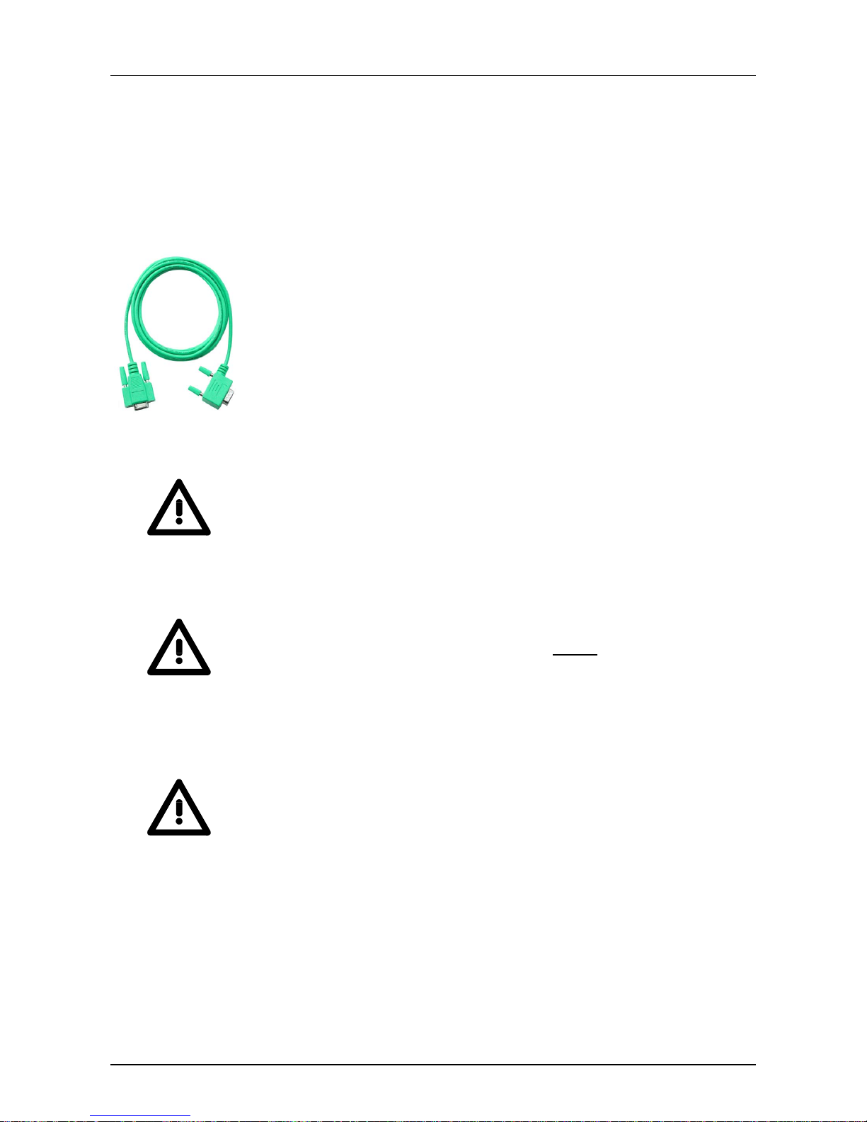
Manual VIPA System 200V Chapter 3 Deployment CPU 21x-2BM03
HB97E - CPU - RE_21x-2BM03 - Rev. 14/44 3-15
The Green Cable is a green connect ion cable, manufactured exclusively for
the deployment at VIPA System components.
The Green Cable is a programming and download cable for VIPA CPUs
MP
2
I jack and VIPA field bus masters. The Green Cable from VIPA is
available under the order no. VIPA 950-0KB00.
The Green Cable allows you to:
• transfer projects serial
Avoiding high hardware needs (MPI transducer, etc.) you may realize a
serial point-to-point connection via the Green Cable and the MP
2
I jack.
This allows you to connect com ponents t o your VIPA-CPU t hat ar e able
to communicate serial via a MPI adapter like e.g. a visualization system.
• execute firmware updates of the CPUs and field bus masters
Via the Green Cable and an upload application you may update the
firmware of all recent VI PA CPUs with MP
2
I jack and certain field bus
masters (see Note).
Important notes for the deployment of the Green Cable
Nonobservance of the following notes may cause damages on system
components.
For damages caused by nonobservance of the following notes and at
improper deployment, VIPA does not take liability!
Note to the application area
The Green Cable may exclusively deployed directly
at the concerning jacks
of the VIPA components (in between plugs are not permitted). E.g. a MPI
cable has to be disconnected if you want to connect a Green Cable.
At this time, the following components support Green Cable:
VIPA CPUs with MP
2
I jack and field bus masters from VIPA.
Note to the lengthening
The lengthening of the Green Cable with another Green Cable res. The
combination with further MPI cables is not permitted and causes damages
of the connected components!
The Green Cable may only be lengthened with a 1:1 cable
(all 9 pins are connected 1:1).
Hints for the
Green Cable

Chapter 3 Deployment CPU 21x-2BM03 Manual VIPA System 200V
3-16 HB97E - CPU - RE_21x-2BM03 - Rev. 14/44
The MMC (Memory Card) serves as external transfer and storage medium.
There may be stored several projects and sub-directories on a MMC
storage module. Please regar d that your current project is stored in the r oot
directory and has one of the following f ile nam es:
• S7PROG.WLD
• S7PROGF.WLD
• AUTOLOAD.WLD
With File > Memory Card File > New in the Siem ens SIMATIC manager a
new wld file may be created. After the creation copy the block s from the
project blocks folder and t he Syst em dat a into the wld file.
The transfer of the application program from the MMC into the CPU takes
place depending on the file name aft er an overall reset or PowerON.
• S7PROG.WLD is read from the MMC after overall reset and transferred
into the battery buffe r ed RAM.
• S7PROGF.WLD is read from the MMC after overall reset and
transferred into the bat tery buffer ed RAM and additionally into the Flash
memory. An access to the Flash memory only takes place at empty
battery of the buffer and when no MMC with user program is plugged-in.
• AUTOLOAD.WLD is read af ter PowerON from the MMC and transferred
into the battery-buffered RAM .
During the transfer the "MC" LED blinks. Please regard that your user
memory serves for enough space, otherwise your user program is not
completely loaded and the SF LED gets on. Execute a com pr ession before
the transfer, f or this does not happen automatically.
When the MMC has been installed, the write command stores t he content
of the battery buffered RAM as S7PROG.WLD on the MMC and in the
internal Flash memory.
The write command is controlled by means of the block area of the
Siemens SIMATIC manager PLC > Copy RAM to ROM. During the write
process the "MC"-LED of the CPU is blinking . When the LED expires the
write process is finished.
If this project is to be loaded aut omatically from the MMC with PowerON,
you have to rename this on the MMC to AUTOLOAD.WLD.
After a MMC access, an ID is written into the diagnostic buffer of the CPU.
To monitor the diagnosis entries, you select PLC > Module Inform ation in
the Siemens SIMATIC manager. Via the register "Diagnostic Buffer" you
reach the diagnosis window.
Information about the Event-I Ds can be found at "VIPA specific diagnostic
entries".
Transfer via
MMC
Transfer
MMC →→→→ CPU
Transfer
CPU →→→→ MMC
Transfer control

Manual VIPA System 200V Chapter 3 Deployment CPU 21x-2BM03
HB97E - CPU - RE_21x-2BM03 - Rev. 14/44 3-17
Operating modes
The CPU can be in one of 3 operating modes:
• Operating mode STOP
• Operating mode START-UP
• Operating mode RUN
Certain conditions in the operating modes START-UP and RUN require a
specific reaction from the system program. In this case the application
interface is often provided by a call to an organization block that was
included specifically for this event.
• The application program is not processed.
• If there has been a processing before, the values of counters, timers,
flags and the process image are retained during the transition to the
STOP mode.
• Outputs are inhibited, i.e. all dig it a l out puts are disabled.
• RUN-LED (R) off
• STOP-LED (S) on
• During the transition from STOP to RUN the system calls the start-up
organization block OB 100. The processing time for this OB is not
monitored. The start-up O B m ay issue calls to ot her blocks.
• All digital outputs are disabled during the start-up, i.e. outputs are
inhibited.
• RUN-LED blinks
as soon as the OB 100 is operated and for at least
3s,
even if the start-up time is shorter or the CPU gets to
STOP due to an error. This indicates the start-up.
• STOP-LED off
When t he CPU has completed the start-up OB, it assumes the operating
mode RUN.
• The application program in OB 1 is processed in a cycle. Under the
control of alarms other program sections can be included in the cycle.
• All timers and counters being started by the progr am are active and the
process image is updated with every cycle.
• The BASP-signal (outputs inhibited) is deact ivated, i.e. all digital outputs
are enabled.
• RUN-LED on
• STOP-LED off
Overview
Operating mode
STOP
Operating mode
START-UP
Operating mode
RUN

Chapter 3 Deployment CPU 21x-2BM03 Manual VIPA System 200V
3-18 HB97E - CPU - RE_21x-2BM03 - Rev. 14/44
The CPUs include security mechanisms like a watchdog (100ms) and a
parameterizable cycle time surveillance (parameterizable min. 1ms) that
stop res. execute a RESET at the CPU in case of an er ror and set it into a
defined STOP state.
The VIPA CPUs are developed function secure and have the following
system properties:
Event concerns Effect
RUN → STOP
general
BASP (Befehls-Ausgabe-Sperre, i.e. command
output lock) is set.
central digital outputs The outputs are disabled.
central analog outputs The Outputs are disabled.
- Voltage outputs issue 0V
- Current outputs 0...20m A issue 0m A
- Current outputs 4...20m A issue 4m A
If configured also subst it ut e values may be
issued.
decentral outputs Same behavior as the central digital/analog
outputs.
decentral inputs T he input s ar e cyclically be read by the decentra-
lized station and the recent values are put at
disposal.
STOP → RUN
res. PowerON
general First the PII is delet ed, then OB 100 is called. After
the execution of the OB, the BASP is reset and the
cycle starts with:
Delete PIO → Read PII → OB 1.
central analog outputs The behavior of the outputs at restart can be
preset.
decentral inputs T he input s ar e cyclically be read by the decentra-
lized station and the recent values are put at
disposal.
RUN general The progra m execution happens cyclically and can
therefore be foreseen:
Read PII → OB 1 → Write PIO.
PII = Process image inputs
PIO = Process image outputs
Function securit
y

Manual VIPA System 200V Chapter 3 Deployment CPU 21x-2BM03
HB97E - CPU - RE_21x-2BM03 - Rev. 14/44 3-19
Overall reset
During the overall reset the entire user m emory is erased. Data located in
the memory card is not affected.
You have 2 options to initiate an overall reset:
• initiate the overall reset by means of the function selector switch
• initiate the overall reset by means of the configuration software e.g.
Siemens SIMATIC manager
Note!
You should always issue an overall reset to your CPU before loading an
application program into your CPU to ensure that all blocks have been
cleared from the CPU.
Condition
The operating mode of the CPU is STOP. Place the function selector on the
CPU in position "ST" → the S-LED is on.
Overall reset
• Place the function select or in the position MR and hold it in this position
for app. 3 seconds. → The S- LED changes from blinking to permanent ly
on.
• Place the function selector in the position ST and switch it to MR and
quickly back to ST within a period of less than 3 seconds.
→ The S-LED blinks (overall reset pr ocedur e).
• The overall reset has been completed when the S-LED is on
permanently. → The S-LED is on.
The following figure illustr ates the above procedure:
R
S
PW
SF
R
S
PW
SF
R
S
PW
SF
R
S
PW
SF
1 2 3 4
3 Sec.
3 Sec.
RN
ST
MR
RN
ST
MR
RN
ST
MR
RN
ST
MR
Overview
Overall reset by
means of the
function selector

Chapter 3 Deployment CPU 21x-2BM03 Manual VIPA System 200V
3-20 HB97E - CPU - RE_21x-2BM03 - Rev. 14/44
If there is a project S7PROG.WLD on the MMC, the CPU attempts to
reload this project from MMC → the MC LED is on.
When the reload has been completed the LED is extinguished. The
operating mode of the CPU will be STOP or RUN, depending on the
position of the function selector .
Condition
The operating mode of t he CPU m u st be STOP.
You may place the CPU in STOP mode by the menu command
PLC > Operating mode.
Overall reset
You may request the overall reset by means of the menu command PLC >
Clean/Reset.
In the dialog window you may place your CPU in STOP mode and start t he
overall reset if this has not been done as yet.
The S-LED blinks during the overall reset procedure.
When t he S-LED is on permanently the overall reset procedure has been
completed.
At this point the CPU attempts t o reload the parameters and the program
from the memory card. → The MC LED is on.
When the reload has been completed, the LED expires. The operating
mode of the CPU will be STOP or RUN, depending on the position of the
function selector.
A Factory reset deletes the internal RAM of t he CPU completely and sets it
back to the delivery state.
Please regard that the MPI address is also set back to default 2!
More information may be found at the part "Factory reset" further below.
Automatic reload
Overall reset by
means of the
Siemens SIMATIC
manager
Automatic reload
Reset to factory
setting

Manual VIPA System 200V Chapter 3 Deployment CPU 21x-2BM03
HB97E - CPU - RE_21x-2BM03 - Rev. 14/44 3-21
Firmware update
There is the opportunity to execute a firm ware update for the CPU and its
components via
MMC. For this an accordingly prepared MMC must be in
the CPU during the startup.
So a firmware files can be recognized and assigned with startup, a file
name is reserved for each updateable component (see t able below).
After PowerON and CPU STOP the CPU check s if there is a firmware file
on the MMC. If this firmware version is different to the existing firmware
version, this is indicated by blinking of the LEDs and t he firmware may be
installed by an update request.
The latest firmware versions are to be found in the service area at
www.vipa.com
A label on the rear of the module indicates t he firmware version.
You may display the current firm ware version of your CPU via the Siemens
SIMATIC manager. To display the f irmware version, you go online with the
CPU via your PG or PC and start the Siemens SIMATIC manager.
Via PLC > Module status, register "General", the current firmware version is
evaluated and displayed.
• Go to www.vipa.com
• Click on Service > Download > Firmware.
• Navigate to via System 200V > CPU to your CPU and download
according to your hardware version the zip file to your PC.
• Open the zip file and copy the bin file to your MMC.
• Rename this accordingly
By means of a reserved file name in the CPU 21x-2BM03 you may transfer
a firmware per MMC:
Component File name
order no._release_version.ZIP
New file name
at MMC
CPU Bx000... .bin firmware.bin
DPM Bx000589.bin dpm00.bin
Overview
Latest Firmware at
www.vipa.com
Find out CPU
firmware version
Load firmware and
transfer it to MMC
with reserved file
name
Reserved file
names
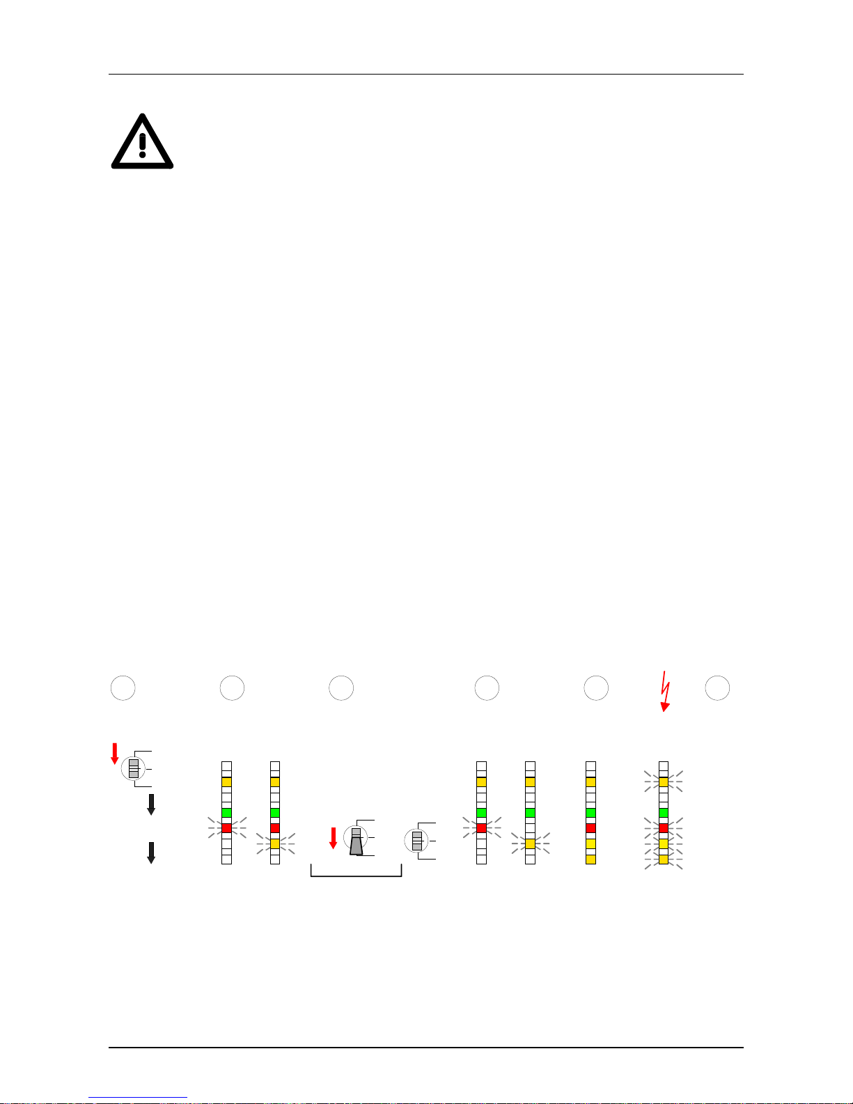
Chapter 3 Deployment CPU 21x-2BM03 Manual VIPA System 200V
3-22 HB97E - CPU - RE_21x-2BM03 - Rev. 14/44
Attention!
When installing a new firmware you have to be extremely caref ul. Under
certain circumstances you m ay destroy the CPU, f or example if t he voltage
supply is interrupted during transf er or if the firmware f ile is defective.
In this case, please call the VIPA-Hotline!
Please regard that the version of the update firmware has to be different
from the existing firm ware other wise no update is executed.
1. Switch the operating mode switch of your CPU in position ST. Turn off
the voltage supply. Plug the MMC with the firmware files into the CPU.
Please take care of the correct plug-in direction of the MMC. Turn on
the voltage supply.
2. After a short boot - up time, the alternate blinking of the LEDs SF and FC
shows that at least a differing firmware file was found on the MMC.
3. You start the tr ansfer of the firmware as soon as you tip the operating
mode switch lever downwards to MR within 10s and leave it in ST
position.
4. During the update process, t he LEDs SF and FC are alternately blinking
and MC LED is on. This may last several minutes.
5. The update is successful finished when the LEDs PW , S, SF, FC and
MC are on. If they are blinking fast , an er r or occurred.
6. Turn Power OFF and ON. Now it is checked by the CPU, whether
further current firmware versions are available at the MMC. If so, ag ain
the LEDs SF and FC flash after a short start-up period. Continue with
point 3.
If the LEDs do not flash, t he firmware update is ready.
Now a factory reset should be executed (see next page). After that the
CPU is ready for duty.
Power OFF/ON
RN
ST
MR
RN
ST
MR
R
S
PW
SF
FC
MC
RN
ST
MR
MMC stecken
R
S
PW
SF
FC
MC
10 Sec.
Tip
R
S
PW
SF
FC
MC
R
S
PW
SF
FC
MC
Preparation Firmware
recognized
at MMC
Start update Update runs
R
S
PW
SF
FC
MC
Update
terminates
error free
R
S
PW
SF
FC
MC
Error
1 2 3 4
Power
OFF/ON
5 6
Transfer firmware
from MMC into
CPU

Manual VIPA System 200V Chapter 3 Deployment CPU 21x-2BM03
HB97E - CPU - RE_21x-2BM03 - Rev. 14/44 3-23
Factory reset
With the following proceeding the internal RAM of the CPU is completely
deleted and the CPU is reset to delivery state.
Please note that here also the MPI address is reset to the address 2!
1. Switch the CPU to STOP.
2. Push t he operating mode switch down to position MR for 30s. Here the
S LED flashes. After a few seconds the stop LED changes to static
light. Now the S LED changes between static light and f lashing. Starting
here count the static light stat es of the S LED.
3. After the 6. static light release the operating mode switch and tip it
downwards to MR. Now the RUN LED lights up once. This means that
the RAM was deleted completely.
4. For the confirm ation of the reset ting procedur e the LEDs PW and S are
on.
5. Then you have to switch the power supply off and on.
The proceeding is shown in the following Illustration:
RN
ST
MR
30 Sec.
Tip
R
S
PW
SF
FC
MC
CPU in
STOP
Request factory reset
Start factory reset
Factory reset
executed
1
3
R
S
PW
SF
FC
MC
R
S
PW
SF
FC
MC
6x
RN
ST
MR
RN
ST
MR
Tip
1 Sec.
2 4
Power
OFF/ON
5
R
S
PW
SF
FC
MC
R
S
PW
SF
FC
MC
Note!
After the firmware update you always should execute a Factory reset.
Proceeding

Chapter 3 Deployment CPU 21x-2BM03 Manual VIPA System 200V
3-24 HB97E - CPU - RE_21x-2BM03 - Rev. 14/44
VIPA specific diagnostic entries
You may read the diagnostic buffer of the CPU via the Siemens SIMATIC
manager. Besides of t he standard ent ries in the diag nost ic buf f er, t he VIPA
CPUs support some additional specific entries in form of event-IDs.
To monitor the diagnostic entries you choose the option PLC > Module
Information in the Siemens SIMATIC manager. Via the register " Diagnostic
Buffer" you reach the diagnost ic window:
Module information
Diagnostic Buffer
Nr.
8
9
10
11
12
13
Time of day
...
...
13:18:11:370
...
...
...
Date
...
...
19.12.2011
...
...
...
Event
...
...
Event-ID: 16# E0CC
...
...
...
Path: Accessible Nodes MPI = 2 Operating mode CPU: RUN
Details:
...
VIPA-ID
... ... ... ...
... ... ... ... ... ...
The diagnosis is independent from the operating mode of the CPU. You
may store a max. of 100 diagnostic entries in the CPU.
The following page shows an overview of the VIPA specific Event-IDs.
Entries in the
diagnostic buffer
Monitoring the
diagnostic entries

Manual VIPA System 200V Chapter 3 Deployment CPU 21x-2BM03
HB97E - CPU - RE_21x-2BM03 - Rev. 14/44 3-25
Event-ID Description
0xE003 Error at access to I/O devices
Zinfo1: I/O address
Zinfo2: Slot
0xE004 Multiple parameterization of a I/O address
Zinfo1: I/O address
Zinfo2: Slot
0xE005 Internal error – Please cont act the VIPA-Hotline!
0xE006 Internal error – Please cont act the VIPA-Hotline!
0xE007 Configured in-/output bytes do not fit into I/O area
0xE008 Internal error – Please cont act the VIPA-Hotline!
0xE009 Error at access to standard back plane bus
0xE010 Not defined module gr oup at backplane bus recognized
Zinfo2: Slot
Zinfo3: Type ID
0xE011 Master project engineering at Slave-CPU not possible or wrong slave configuration
0xE012 Error at paramet er ization
0xE013 Error at shift register access to VBUS digital modules
0xE014 Error at Check_Sys
0xE015 Error at access to the mast er
Zinfo2: Slot of the mast er ( 32=page frame master)
0xE016 Maximum block size at master transfer exceeded
Zinfo1: I/O address
Zinfo2: Slot
0xE017 Error at access to integ r ated slave
0xE018 Error at mapping of the master I/O devices
0xE019 Error at standard back plane bus system r ecognition
0xE01A Error at r ecognition of the operating m ode ( 8 / 9 Bit)
0xE0CC Communication er ror MPI / Serial
0xE100 MMC access error
0xE101 MMC error file system
0xE102 MMC error FAT
0xE104 MMC error at saving
0xE200 MMC writing finished (Copy Ram to Rom)
0xE210 MMC reading finished (reload after overall r eset)
0xE300 Internal Flash writing ready (Copy RAM to ROM)
0xE310 Internal Flash reading finished (reload after batter y failure)
Overview of the
Event-IDs

Chapter 3 Deployment CPU 21x-2BM03 Manual VIPA System 200V
3-26 HB97E - CPU - RE_21x-2BM03 - Rev. 14/44
Using test functions for control and monitoring of variables
For troubleshooting purposes and to display the status of certain variables
you can access certain test functions via the menu item Debug of the
Siemens SIMATIC manager.
The status of the operands and the VKE can be displayed by means of the
test function Debug > Monitor.
You can modify and/or display the status of variables by means of the test
function PLC > Monitor/Modify Variables.
This test function displays the current st atus and the VKE of the different
operands while the program is being executed.
It is also possible to enter corrections to the program.
Note!
When using t he t est function “Monitor” the PLC must be in RUN mode!
The processing of the states may be interrupted by means of jump
commands or by timer and process-related alarms. At the breakpoint the
CPU stops collecting data for the st atus display and instead of the requir ed
data it only provides the PG with data containing the value 0.
For this reason, jumps or time and process alar ms can result in the value
displayed during program execution remaining at 0 for the items below:
• the result of the logical operation VKE
• Status / AKKU 1
• AKKU 2
• Condition byte
• absolute memory address SAZ. In this case SAZ is followed by a "?".
The interruption of the processing of statuses does not change the
execution of the program. It only shows that the data displayed is no longer.
Overview
Debug > Monitor

Manual VIPA System 200V Chapter 3 Deployment CPU 21x-2BM03
HB97E - CPU - RE_21x-2BM03 - Rev. 14/44 3-27
This test function returns the condition of a selected operand (inputs,
outputs, flags, data word, counters or timers) at the end of programexecution.
This information is obtained from the process image of the selected
operands. During the "processing check " or in operating mode STOP the
periphery is read directly from the inputs. Otherwise only the process image
of the selected operands is displayed.
Control of outputs
It is possible to check the wiring and proper operation of output-modules.
You can set outputs to any desired status with or without a control program.
The process image is not modified but outputs are no longer inhibited.
Control of variables
The following variables may be modified:
I, Q, M, T, C and D.
The process image of binary and digital operands is modified independently
of the operating mode of the CPU.
When the operating mode is RUN the program is executed with the
modified process variable. When the program continues they may,
however, be modified again without notification.
Process variables are controlled asynchronously to the execution sequence
of the program.
PLC >
Monitor/Modify
Variables

Chapter 3 Deployment CPU 21x-2BM03 Manual VIPA System 200V
3-28 HB97E - CPU - RE_21x-2BM03 - Rev. 14/44

Manual VIPA System 200V Chapter 4 PROFIBUS communication
HB97E - CPU - RE_21x-2BM03 - Rev. 14/44 4-1
Chapter 4 PROFIBUS communication
Content of this chapter is the deployment of the 21x-2BM03 with
PROFIBUS. After a short introduction into the PROFIBUS system, the
project engineering and the usag e with PROFI BUS is shown.
This chapter ends with information about commissioning and start-up
behavior of the DP master.
Topic Page
Chapter 4
PROFIBUS communication............................................4-1
Overview..............................................................................................4-2
Project engineering CPU with integrated PROFIBUS DP master .........4-5
PROFIBUS installation guidelines ........................................................4-7
Commissioning and Start-up behavior................................................4-11
Overview
Content

Chapter 4 PROFIBUS communication Manual VIPA System 200V
4-2 HB97E - CPU - RE_21x-2BM03 - Rev. 14/44
Overview
PROFIBUS is an international standard applicable to an open and serial
field bus for building, manufacturing and process automation that can be
used to create a low (sensor-/actuator level) or medium (process level)
performance network of pr ogrammable logic controllers.
PROFIBUS comprises an assortment of compatible versions. The following
details refer to PROFIBUS DP.
PROFIBUS DP is a special protocol intended mainly for automation tasks in
a manufacturing environment. DP is very fast, offers Plug'n'Play facilities
and provides a cost-effective alternative to parallel cabling between PLC
and remote I/O. PROFIBUS DP was designed for high-speed data communication on the sensor-actuator level.
The data transfer referred to as "Data Exchange" is cyclical. During one bus
cycle, the master reads input values from the slaves and writes output
information to the slave.
PROFIBUS distinguishes between active stations (masters) and passive
stations (slaves).
Master equipment
Master equipment controls the data traf fic on the bus. There may be also
several masters at one PRO FIBUS. T his is referred to as multi master operation. The bus protocol establishes a logical t oken ring between the intelligent devices connected to the bus.
A master of the CPU 21xDPM may send unsolicited messages if it has the
bus access permission (Token). In the PROFIBUS protocol masters are
also referred to as active stations.
Slave equipment
Typical slave equipment holds data of peripheral equipment, sensors,
actuators or transducers. The VIPA PROFIBUS are modular slave
equipment, transfer ring data between the System 200V periphery and the
leading master.
These devices do not have bus access permission in accordance with the
PROFIBUS standard. They may only acknowledge messages or transfer
messages to a master if requested by this. Slaves occupy a very limited
part of the bus protocol. Slaves are also referred to as passive stations.
PROFIBUS DP
Master and slaves

Manual VIPA System 200V Chapter 4 PROFIBUS communication
HB97E - CPU - RE_21x-2BM03 - Rev. 14/44 4-3
The bus communication protocol provides two procedures for accessing the
bus:
Communications with the master is also referred to as token passing
procedure. Token passing guarantees that the station receives access
permission to the bus. T his access right to the bus is passed between the
stations in form of a "token". A token is a specific message that is
transferred via the bus.
When a master possesses t he token, it has the access right to the bus and
is allowed to communicate with all other active and passive stations. The
token retention time is def ined when the system is being configured. W hen
the token retent ion time has expired, the token is passed along to the next
master that acquires the bus access rig hts with the token so that this may
now communicate with all other stations.
Data is exchanged in a fixed repetit ive sequence between the master and
the slaves assigned to this respective master. When you configure the
system, you define which slaves are assigned to a certain m ast er. You may
also specify which DP slave is included in the cyclic exchange of
application data and which ones are excluded.
The master slave data t ransfer is divided into parameterization, config uration and data transfer phases. Bef ore a DP slave is included into the data
transfer phase, the master verifies during the parameterization and configuration phase whether the specified configur ation agrees with the effective
configuration. This verif ication process checks the device type, format and
length as well as the number of inputs and outputs. This provides you with
effective protection against configuration errors.
The master handles application data transfers independently. In addition
you may also send new configuration data to a bus coupler.
If in the status DE „Data Exchange“, the master is sending new basic data
to the slave and the receipt of t he slave transfers the recent input data to
the master.
Data is referr ed to as being consistent, if it has the same logical contents.
Data that belongs together is: the high- and low-byte of an analog value
(word consistency) and the control and t he status byte with the respective
parameter word, required to access the reg ist er s.
The data consistency during the interaction between the peripherals and
the controller is only g uaranteed f or 1Byte. T hat is, the bits of one byte are
acquired together and they are transm itted tog ether. Byte- wise consistency
is sufficient for the processing of digital signals.
Communication
Master to Master
Master slave
procedure
Data consistenc
y

Chapter 4 PROFIBUS communication Manual VIPA System 200V
4-4 HB97E - CPU - RE_21x-2BM03 - Rev. 14/44
As transfer m edium PROFIBUS uses an isolated drilled 2 core line based
upon the RS485 interface or a duplex optical waveguide (OWG). The
transfer rate is for both methods max. 12Mbaud.
The RS485 interface is working with voltage dif ferences. Though it is less
irritable from f ailures than a voltage or a current interf ace. You are able to
configure the network as well linear as in a tree structure. Your VIPA
PROFIBUS coupler includes a 9pin slot where you link up the PROFI BUS
coupler into the PROFIBUS network as a slave.
The bus structure under RS485 allows an easy connection resp.
disconnection of stations as well as starting the system step by step. Later
expansions don’t have any influence on stations that are already integrated.
The system realizes automatically if one partner had a f ail down or if it is
new in the network.
The optical waveguide system uses monochromatic light impulses. The
optical waveguide is totally independent fr om disturbing voltage f rom other
machines. An optical waveguide system is built up linear. Every module
has to be connected with two links: one input link and one back. You don’t
need to terminate the last module.
For the structure is a linear one, connecting and disconnect ing stations is
not free of consequences.
Every partner of the PROFIBUS network has to identif y itself with a certain
address. This address may be existing only one time in the bus system and
has a value between 0 and 125.
At the CPU 21xDPM you choose the address via your software tool.
To configure the slave connections in your own config uration tool, you’ve
got all the information about your VIPA modules in form of an electronic
data sheet file (German: Gerätestammdatei = GSD-file).
Structure and content of this file are dictated by the PROFIBUS User
Organization (PNO) and may be seen there.
Install the GSD-file in your conf iguration tool. Look for more infor mation in
the online help of the according tool.
Transfer medium
Electrical system
over RS485
Optical system via
fiber optic (FO)
Addressing
Electronic Data
Sheet
(GSD-file)

Manual VIPA System 200V Chapter 4 PROFIBUS communication
HB97E - CPU - RE_21x-2BM03 - Rev. 14/44 4-5
Project engineering CPU with integrated PROFIBUS DP master
For the project engineering of the PROFIBUS DP master you have to use
the hardware manager from Siemens. Your PROFIBUS projects are
transferred via MPI into the CPU 21x-2BM03 by means of the PLC
functions. The CPU passes the data on to t he PROFIBUS DP master.
Note!
For the project engineering of the CPU and the PROFIBUS DP master a
thorough knowledge of the SI MATIC manager and t he hardware config urator from Siemens is required!
To be compatible to the Siemens SIMATIC manager , for the System 200V
the following steps are necessary:
• Configure the CPU 315-2DP with the DP master system ( addr ess 2) .
• Add from the VIPA_21x.gsd t he PROFIBUS slave "VIPA_CPU21x" with
address 1.
• Insert the CPU 21x-2BM03 at the 1. slot of the slave system.
• Include the directly plugged peripheral modules at t he sequencing slots.
• Install the according GSD file for the slave system.
• select from the hardware catalog the accor ding slave system and drag it
to the master system.
• Configure the according periphery modules of the slave system
• Transfer the project to the CPU 21x-2BM03.
Overview
Fast introduction
Master-System
Slave system

Chapter 4 PROFIBUS communication Manual VIPA System 200V
4-6 HB97E - CPU - RE_21x-2BM03 - Rev. 14/44
• Start the Siemens SIMATIC manager and config ure a CPU as described
at "Hardware configuration - CPU" .
• Designate the station as "...DP master"
• Add your modules according to the real hardware assembly.
Module
CPU 21x-2BM03
Centralized Periph.
...
...
Slot
0
1
2
...
PBAddr.:1
PBAddr.:2
(1) VIPA_CPU
CPU 21x
CPU 214
PW
SF
FC
MC
R
S
RN
ST
MR
MMC
2
Module
CPU 315-2DP
DP
Slot
1
2
X2
3
PROFIBUS (1): DP master system
• Install the corresponding GSD file of your slave system in the hardware
configurator.
• Search the corresponding PROFIBUS DP slave in the hardware catalog
and drag&drop it to the subnet of your m ast er .
• Assign a valid PROFIBUS address >3 to the DP slave
• Add your modules according to the real hardware assembly.
Module
CPU 21x-2BM03
Centralized Pe rip h.
...
...
Slot
0
1
2
...
PBAddr.:1
PBAddr.:2
(1) VIPA_CPU
CPU 21x
CPU 214
PW
SF
FC
MC
R
S
RN
ST
MR
MMC
2
Module
CPU 315-2DP
DP
Slot
1
2
X2
3
PROFIBUS (1): DP master system
Module
Periphery slave
...
...
...
Slot
0
1
2
...
DP-Slave...
CPU 214
PW
SF
FC
MC
R
S
RN
ST
MR
MMC
2
PBAddr.:3 ... 125
...
• Transfer your project to the CPU 21x-2BM03.
Configuration of
the master system
Configuration of t he
DP slaves
Transfer the project

Manual VIPA System 200V Chapter 4 PROFIBUS communication
HB97E - CPU - RE_21x-2BM03 - Rev. 14/44 4-7
PROFIBUS installation guidelines
• A PROFIBUS DP network may only be built up in linear structure.
• PROFIBUS DP consists of minimum one segment with at least one
master and one slave.
• A master has always been deployed together with a CPU.
• PROFIBUS supports max. 126 participants.
• Per segment a max. of 32 participant s is per m it t ed.
• The max. segment length depends on the baud r at e:
9.6 ... 187.5kbaud → 1000m
500kbaud → 400m
1.5Mbaud → 200m
3 ... 12Mbaud → 100m
• Max. 10 segments may be built up. The segments are connected via
repeaters. Every repeater counts for one participant.
• The bus respectively a segment is to be terminated at bot h ends.
• All participants are communicating with the same baud rate. The slaves
adjust themselves automatically on the baud rate.
As transfer medium PROFIBUS uses an isolat ed twisted-pair cable based
upon the RS485 interface.
The RS485 interface is working with voltage dif ferences. Though it is less
irritable from influences than a voltage or a curr ent interface. You are able
to configure the network as well linear as in a tr ee structure.
Max. 32 participants per segment are permitted. Within a segment the
members are linear connected. The segm ent s are connected via repeaters.
The maximum segment length depends on the t r ansfer rate.
PROFIBUS DP uses a tr ansfer rate between 9.6kbaud and 12Mbaud, the
slaves are following automatically. All participants are communicating with
the same transfer rate.
The bus structure under RS485 allows an easy connection res.
disconnection of stations as well as starting the system step by step. Later
expansions don’t have any influence on stations that are already integrated.
The system realizes automatically if one partner had a f ail down or is new
in the network.
PROFIBUS in
general
Transfer medium

Chapter 4 PROFIBUS communication Manual VIPA System 200V
4-8 HB97E - CPU - RE_21x-2BM03 - Rev. 14/44
The following picture illustr ates the terminating resistors of the respective
start and end station.
RxD/TxD-P(B)
Shield
Master
Slave
3
8
3
8
P5V P5V
M5V M5V
330 330
330 330
220 220
3
8
RxD/TxD-N(A)
5
6
RxD/TxD-P(B)
RxD/TxD-N(A)
Slave
RxD/TxD-P(B)
RxD/TxD-N(A)
5
3
8
6
Shield
Shield
Note!
The PROFIBUS line has to be terminated with its ripple resistor. Please
make sure to terminate the last participants on the bus at both ends by
activating the terminating resistor .
In PROFIBUS all participants ar e wired parallel. For that purpose, the bus
cable must be feed-through.
Via the order number VIPA 972-0DP10 you may order the bus connector
"EasyConn". This is a bus connector with switchable terminating resistor
and integrated bus diagnostic.
C
A
B
90°
A
B
0°
B
A
45°
0° 45° 90°
A 64 61 66
B 34 53 40
C 15.8 15.8 15.8
in mm
Bus connection
EasyConn
bus connector

Manual VIPA System 200V Chapter 4 PROFIBUS communication
HB97E - CPU - RE_21x-2BM03 - Rev. 14/44 4-9
Note!
To connect this EasyConn plug , please use the st andard PROFIBUS cable
type A (EN50170). Starting with release 5 you also can use highly flexible
bus cable: Lapp Kabel order no.: 2170222, 2170822, 2170322.
With the or der no. 905-6AA00 VIPA off ers the "EasyStrip" de-isolating tool
that makes the connection of the EasyConn much easier .
11 6
Dimensions in mm
The "EasyConn" bus connector is provided with a switch that is used to
activate a terminating resistor.
1./last
bus participant
further
participants
Attention!
The terminating resistor is only effec-
tive, if the connector is installed at a bus
participant and the bus participant is
connected to a power supply.
Note!
A complete description of installation
and deployment of the terminating
resistors is delivered with the connector.
• Loosen the screw.
• Lift contact-cover.
• Insert both wires into the ducts
provided (watch for the correct
line color as below!)
• Please take care not to cause a
short circuit between screen and
data lines!
• Close the contact cover.
• Tighten screw
(max. tightening torque 4Nm).
The green line must be connected to A, the red line to B!
Termination with
"EasyConn"
Wiring
Assembly
Please note:

Chapter 4 PROFIBUS communication Manual VIPA System 200V
4-10 HB97E - CPU - RE_21x-2BM03 - Rev. 14/44
Commissioning and Start-up behavior
In delivery the CPU is overall reset. The PROFIBUS part is deactivated and
its LEDs are off af ter Power ON.
The DP master can be served with bus parameters by means of a
hardware configuration. As soon as these are transferred the DP master
goes online with his bus parameter. This is shown by the RUN LED. Now
the DP master can be contacted via PROFIBUS by means of his
PROFIBUS address. In this state the CPU can be accessed via PROFIBUS
to get configurat ion and DP slave project.
If the master has received valid configuration data, he switches to Data
Exchange with the DP Slaves. This is indicated by the DE-LED.
After PowerON respect ively a receipt of a new hardware configuration the
configuration data and bus paramet er were tr ansferred to the DP master.
Dependent on the CPU state the following behavior is shown by the DP
master:
• The global control command "Clear" is sent to the slaves by the master.
Here the DE-LED is blinking.
• DP slaves with fail safe mode were provided with output telegram length
"0".
• DP slaves without fail safe mode were provided with the whole output
telegram but with output data = 0.
• The input data of the DP slaves were furt her cyclically transferred t o the
input area of the CPU.
• The global control command "Operate" is sent to the slaves by the
master. Here the DE-LED is on.
• Every connected DP slave is cyclically attended with an output telegram
containing recent output data.
• The input data of the DP slaves were cyclically transferred to the input
area of the CPU.
Start-up on
delivery
Online with bus
parameter without
slave project
Slave
configuration
CPU state controls
DP master
Master behavior at
CPU STOP
Master behavior at
CPU RUN
 Loading...