

Page 1

VIPA System 100V
SM-PB | Manual
HB100E_SM-PB | Rev. 13/04
January 2013
Page 2

Copyright © VIPA GmbH. All Rights Reserved.
This document contains proprietary information of VIPA and is not to be disclosed or used except in accordance with applicable
agreements.
This material is prot ected by the copyright laws. It may not be reproduced, distributed, or al tered in any fashion by any entity (either
internal or external to VIPA), except in ac cordance with applicable agreements, contracts or licensing, without the express written
consent of VIPA and the business management owner of the material.
For permission to reproduce or dis tribute, please contact:
VIPA, Gesellsc haft für Visualisierung und Prozes sautomatisierung mbH
Ohmstraße 4, D-91074 Herzogenaurach, Germany
Tel.: +49 (91 32) 744 -0
Fax.: +49 9132 744 1864
EMail: [email protected]
http://www.vipa.com
Note
Every effort has been made to ens ure that the information cont ai ned i n this document was compl ete and accurate at the tim e of
publishing. Nevertheless, the authors retain the right to m odi fy the information. This customer document des cribes all the hardware
units and functions known at t he present time. Descriptions may be included for units which are not present at the customer site. The
exact scope of delivery is descri bed i n the respective purchase contract.
CE Conformity Declaration
Hereby, VIPA GmbH declares that the products and syst ems are in compliance with t he essential requirements and ot her rel evant
provisions.
Conformity is indicated by the CE marking affixed to the product.
Conformity Information
For more information regarding CE marking and Declaration of Conformity (DoC), please contact your l ocal VIPA customer service
organization.
Trademarks
VIPA, SLIO, Sys tem 100V, System 200V, System 300V, Sys t em 300S, System 400V, System 500S and Commander Compact are
registered trademarks of VIPA Gesellschaft f ü r V i sualisierung und Prozessautom atisierung mbH.
SPEED7 is a registered t rademark of profichip GmbH.
SIMATIC, STEP, SINEC, TIA Portal, S7-300 and S7-400 are registered trademarks of Siemens AG.
Microsoft und Wi ndows are registered trademarks of Micros oft Inc., USA.
Portable Document Form at (PDF) and Postscript are regist ered trademarks of Adobe Systems, Inc.
All other trademarks, logos and service or product marks specified herein are owned by their respective companies.
Information product support
Contact your local VIPA Customer Service Organization repres entative if you wish to report errors or questions regarding the contents
of this document. If you are unable to locate a customer service center, contact VIPA as follows:
VIPA GmbH, Ohmstraße 4, 91074 Herzogenaurach, Germany
Telefax:+49 9132 744 1204
EMail: [email protected]
Technical support
Contact your local VIPA Customer Service Organization repres entative if you encounter problems with the product or have questions
regarding the product. If you are unable to l ocate a customer servic e center, contact VIPA as follows:
VIPA GmbH, Ohmstraße 4, 91074 Herzogenaurach, Germany
Telephone: +49 9132 744 1150 (Hotline)
EMail: [email protected]
Page 3

Manual VIPA System 100V Contents
HB100E - SM-PB - Rev. 13/04 i
Contents
About this manual....................................................................................1
Safety information.................................................................................... 2
Chapter 1
Basics..............................................................................1-1
Safety information for Users.................................................................1-2
Overview System 100V........................................................................1-3
General Description of the System 100V..............................................1-4
Assembly dimensions...........................................................................1-5
Chapter 2 Decentral block periphery PROFIBUS DP.....................2-1
Principles..............................................................................................2-2
System overview..................................................................................2-6
Structure ..............................................................................................2-7
Assembly and cabling ........................................................................ 2-13
Link up to PROFIBUS ........................................................................2-14
Commissioning...................................................................................2-17
Diagnostic..........................................................................................2-18
Circuit diagrams................................................................................. 2-21
Technical Data................................................................................... 2-22
Page 4

Contents Manual VIPA System 100V
ii HB100E - SM-PB - Rev. 13/04
Page 5

Manual VIPA System 100V About this manual
HB100E - SM-PB - Rev. 13/04 1
About this Manual
This manual describes the available System 100V decentral block
periphery PROFIBUS from VIPA. Besides of a product overview you will
find the detailed description of the single components.
You'll get information about installing and operating a decentral block
periphery in a PROFIBUS DP system.
Chapter 1: Basics
This introduction includes recommendations on the handling of the
modules of the VIPA System 100V as central resp. decentral automation
system.
Besides a system overview you will find general information to the System
100V like dimensions, installation and operating conditions.
Chapter 2: Decentral block periphery PROFIBUS
The decentral block periphery consists of a PROFIBUS DP slave and I/O
components.
The decentral block periphery is available in different variants described in
this chapter.
This chapter includes all information required for assembly, project
engineering and operating this System 100V com ponents.
Overview
Page 6
About this manual Manual VIPA System 100V
2 HB100E - SM-PB - Rev. 13/04
This manual describes the System 100V decentral block periphery
PROFIBUS from VIPA. It contains a description of the construction, project
implementation and usage.
This manual is part of the document at ion package with order number
HB100E_SM-PB and relevant for:
Product Order number as of state:
HW
SM-PB VIPA 15x-xxxx 01
The manual is targeted at users who have a background in automation
technology.
The manual consists of chapters. Every chapter provides a self-contained
description of a specific topic.
The following guides are available in the manual:
• an overall table of contents at the beginning of the manual
• an overview of the topics for every chapter
The manual is available in:
• printed form, on paper
• in electronic form as PDF-f ile (Adobe Acrobat Reader)
Important passages in the text are highlighted by following icons and
headings:
Danger!
Immediate or likely danger.
Personal injury is possible.
Attention!
Damages to property is likely if t hese warning s ar e not heeded.
Note!
Supplementary information and usef ul t ips.
Objective and
contents
Target audience
Structure of the
manual
Guide to the
document
Availability
Icons
Headings
Page 7
Manual VIPA System 100V Safety information
HB100E - SM-PB - Rev. 13/04 3
Safety information
The System 100V is constructed and manufactur ed for
• communication and process control
• general control and automation applications
• industrial applications
• operation within the environmental conditions specified in the technical
data
• installation into a cubicle
Danger!
This device is not certified for applicat ions in
• in explosive environments (EX-zone)
The manual must be available to all personnel in the
• project design department
• installation department
• commissioning
• operation
The following conditions must be met bef ore usi ng or commissioning
the components described in this manual:
• Hardware modifications to the process control system should only be
carried out when the system has been disconnected from power!
• Installation and hardware modification only by properly trained
personnel.
• The national rules and regulations of the respective country must be
satisfied (installation, safety, EMC ...)
National rules and regulations apply to the disposal of t he uni t !
Applications
conforming with
specifications
Documentation
Disposal
Page 8

Safety information Manual VIPA System 100V
4 HB100E - SM-PB - Rev. 13/04
Page 9

Manual VIPA System 100V Chapter 1 Basics
HB100E - SM-PB - Rev. 13/04 1-1
Chapter 1 Basics
This introduction includes recommendations on the handling of the
modules of the VIPA System 100V as central resp. decentral automation
system.
Besides a system overview you will find general information to the System
100V like dimensions, installation and operating conditions.
Topic Page
Chapter 1
Basics..............................................................................1-1
Safety information for Users.................................................................1-2
Overview System 100V........................................................................1-3
General Description of the System 100V..............................................1-4
Assembly dimensions...........................................................................1-5
Overview
Content
Page 10
Chapter 1 Basics Manual VIPA System 100V
1-2 HB100E - SM-PB - Rev. 13/04
Safety information for Users
VIPA modules make use of highly integrated components in MOStechnology. These components are extremely sensitive to over-voltages
that can occur during electrostatic discharges.
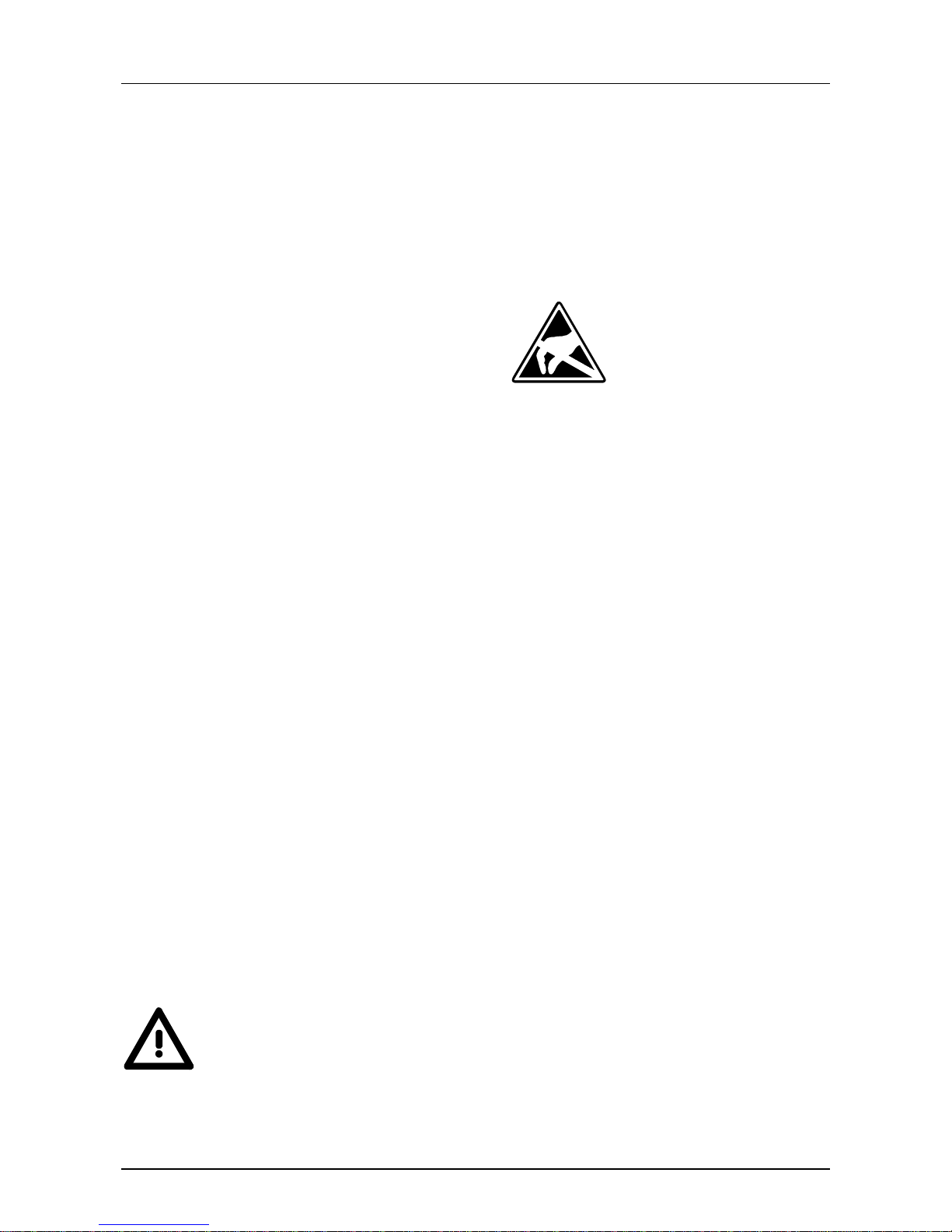
The following symbol is attached to modules that can be destroyed by
electrostatic discharges:
The symbol is located on the module, the module rack or on packing
material and it indicates the presence of elect r ostatic sensitive equipment.
It is possible that electrostatic sensitive equipm ent is destr oyed by energies
and voltages that are far less than the human threshold of perception.
These voltages can occur where persons do not discharge themselves
before handling electrostatically sensitive modules and they can damage
components thereby, causing the module to become inoperable or
unusable. Modules that have been damaged by electrostatic discharges
may fail after a temper ature change, mechanical shock or changes in the
electrical load.
Only the consequent implementation of protection devices and meticulous
attention to the applicable rules and regulat ions for handling the respective
equipment can prevent failures of electrostatically sensitive modules.
Modules have to be shipped in the original packing material.
When you are conducting measurements on electrostatically sensitive
modules you should take the following precautions:
• Floating instruments must be discharged before use.
• Instruments must be grounded.
Modifying electrostatically sensitive modules you should only use soldering
irons with grounded tips.
Attention!
Personnel and instruments should be grounded when working on
electrostatically sensitive modules.
Handling of
electrostatically
sensitive modules
Shipping of
electrostatically
sensitive modules
Measurements
and alterations on
electrostatically
sensitive modules
Page 11
Manual VIPA System 100V Chapter 1 Basics
HB100E - SM-PB - Rev. 13/04 1-3
Overview System 100V
The System 100V from VIPA is a compact central and decentral usable
automation system from VIPA. The system is recommended for lower and
middle performance needs.
At a System 100V module, CPU res. bus coupler are int egrated together
with in-/output functions in one case.
System 100V modules are installed directly to a 35mm norm profile rail.
You may expand the number of I/Os of the Micro-PLC by means of
expansion modules res. connect System 200V modules via bus couplers.
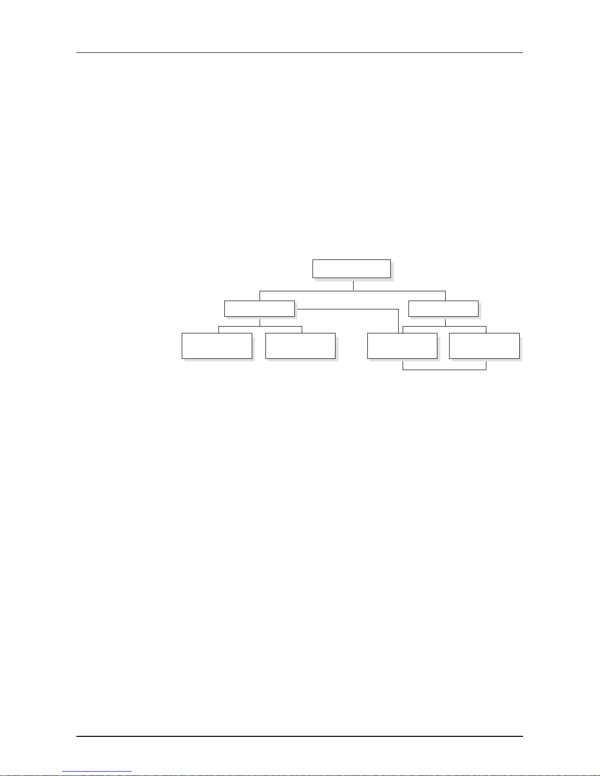
The following picture shows the performance r ange of the System 100V:
System 100V
decentral
PROFIBUS DP slave
with I/O functions
Micro-PLC
with I/O functions
System 100V expansion modules
S
y
stem 200V modules
expandable with
central
Micro-PLC
with I/O functions and
PROFIBUS DP slave
CANopen slave
with I/O functions
The central system is built of one CPU and integrated I/O-functions. The
CPU is instruction compatible to the S7-300 from Siemens and may be
programmed and projected by means of S7 programming tools from
Siemens and VIPA via MPI.
By means of bus couplers you may connect modules of the System 200V
family res. enlarge the number of I/Os by installing System 100V expansion
modules.
The CPUs are available in different variants.
At the central system besides the CPU and I/O functions, a PROFIBUS DP
slave is included that acknowledges itself within the address range of the
CPU.
This system contains a PROFIBUS DP res. CANopen slave with I/O
functions instead of the CPU. The system is not expandable.
General
Central system
Central system
with DP slave
Decentral system
Page 12
Chapter 1 Basics Manual VIPA System 100V
1-4 HB100E - SM-PB - Rev. 13/04
General Description of the System 100V
• Norm profile head rail 35mm
• Dimensions basic module:
4tier width: (WxHxD) in mm: 101. 6x76x48 / in inches: 4x3x1.9
6tier width: (WxHxD) in mm: 152. 4x76x48 / in Inches: 6x3x1.9
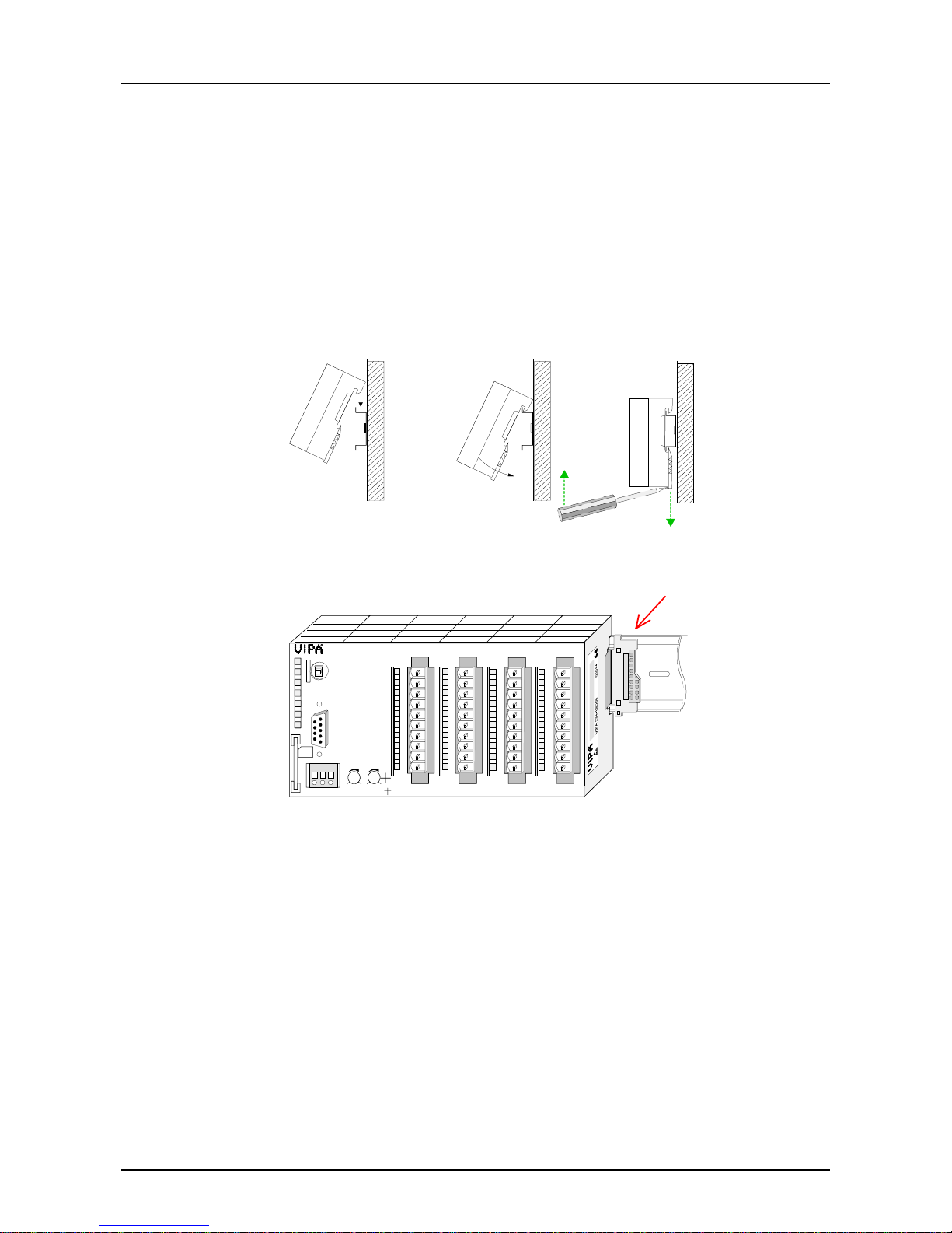
The installation of a System 100V module works via snapping on a norm
profile head rail.
Ç Ç
Dismantling
When using expansion modules, you have to clip the included 1tier bus
connector at the right side to the module from behind before the
installation.
VIPA 115-6BL02
CPU 115
P1 P2
X1
DC24V
MMC
M
P
I
2
00
PW
SF
FC
MC
L+ M PE
X2
34
R
S
RUN
STOP
MRST
DI 8xDC24V
.0
.1
.2
.3
.4
.5
.6
.7
1
2
3
4
5
6
7
8
9
I0
DI 8xDC24V
.0
.1
.2
.3
.4
.5
.6
.7
1
2
3
4
5
6
7
8
9
I0
DO 8xDC24V
L+
.0
.1
.2
.3
.4
.5
.6
.7
F
1
2
3
4
5
6
7
8
9
I0
DO 8xDC24V
L+
.0
.1
.2
.3
.4
.5
.6
.7
F
1
2
3
4
5
6
7
8
9
I0
X3 X4 X5 X6
AB
DI 16(20)xDC24V
DI 16(20)xDC24V, 0,5A
• Plug in via CageClamps, core cross-section 0.08...2.5mm
2
• Total isolation of the cables during module changes
• EMV resistance ESD/Burst acc. IEC 61000-4-2 / IEC 61000-4-4
(to level 3)
• Shock resistance acc. IEC 60068-2-6 / IEC 60068- 2- 27 ( 1G/12G)
• Operating temperature: 0... + 60°C
• Storage temperature: -25... + 70°C
• Relative humidity: 5 ... 95% without condensation
• fan-less operation
Structure and
dimensions
Installation
Operation security
Environmental
conditions
Page 13
Manual VIPA System 100V Chapter 1 Basics
HB100E - SM-PB - Rev. 13/04 1-5
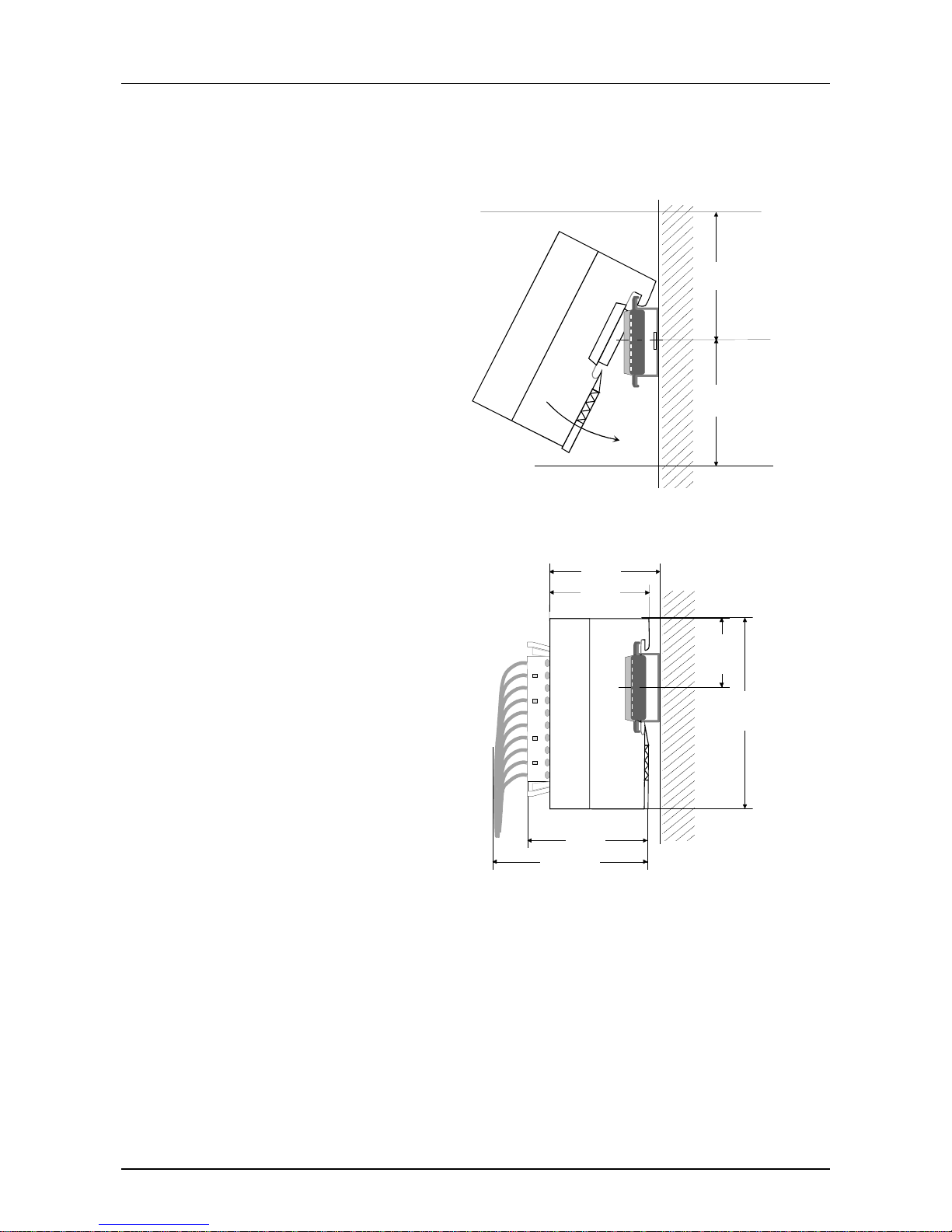
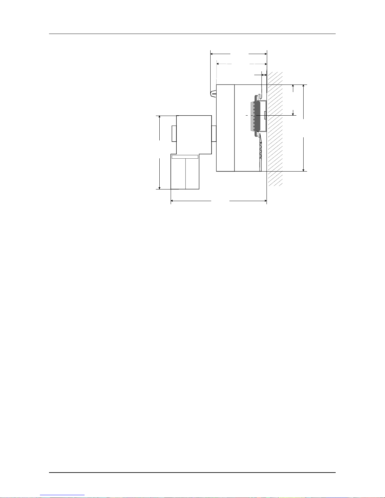
Assembly dimensions
60 mm
60 mm
44 mm
34 mm
48 mm
ca. 70 mm
45 mm
76,62 mm
76 mm
2,77 cm
24 mm
Installation
dimensions
Installed and
wired dimensions
Page 14
Chapter 1 Basics Manual VIPA System 100V
1-6 HB100E - SM-PB - Rev. 13/04
50 mm
27 mm
8 cm
76 mm
8 cm
85 mm
51 mm
65 mm
24 mm
5 mm
11 mm
45 mm
CPU 11x with
EasyConn from
VIPA
Page 15

Manual VIPA System 100V Chapter 2 Decentral block periphery PROFIBUS DP
HB100E - SM-PB - Rev. 13/04 2-1
Chapter 2 Decentral block periphery PROFIBUS DP
The decentral block periphery consists of a PROFIBUS DP slave and I/O
components.
The decentral block periphery is available in different variants described in
this chapter.
This chapter includes all information required for assembly, project
engineering and operating this System 100V com ponents.
Topic Page
Chapter 2
Decentral block periphery PROFIBUS DP.....................2-1
Principles..............................................................................................2-2
System overview..................................................................................2-6
Structure ..............................................................................................2-7
Assembly and cabling ........................................................................ 2-13
Link up to PROFIBUS ........................................................................2-14
Commissioning...................................................................................2-17
Diagnostic..........................................................................................2-18
Circuit diagrams................................................................................. 2-21
Technical Data................................................................................... 2-22
Overview
Content
Page 16

Chapter 2 Decentral block periphery PROFIBUS DP Manual VIPA System 100V
2-2 HB100E - SM-PB - Rev. 13/04
Principles
All the modules in this chapter have got the UL Cert ification:
PROFIBUS is an open fieldbus standard for building, manufacturing and
process automation. PROFIBUS defines the technical and functional
properties of a serial f ield-bus system that can be used t o create a network
of decentral digital field-automation equipment on the lower
(sensor/actuator level) to middle performance level (process level).
PROFIBUS comprises various compatible versions. The specifications
contained in this description refer t o PRO FIBUS DP.
PROFIBUS DP is particularly suitable for applications in production automation. DP is very fast, of f ers Plug 'n'Play and is a cost-ef f ective alternative
to parallel cabling between PLC and the decentral periphery. PROFIBUS
DP is conceived for high-speed data exchange on the sensor/actuator
level. This is where central controllers like PLCs communicate via fast,
serial connections with decentral in- and output devices.
During a single bus cycle the master executes one "Data Exchange", i.e.
reads the input values from the various slaves and writes new output
information into the slaves.
PROFIBUS distinguishes between active stations (masters) and passive
stations (slaves).
Master devices
Master equipment controls the data traffic on the bus. There may be
several masters at one PROFIBUS. This is referred to as multi-master
operation. The bus pr otocol establishes a log ical tok en ring between the intelligent devices connected to the bus.
A master may send unsolicited messages if it has the bus access
permission (Token). In the PROFIBUS protocol these masters are also
referred to as active stations.
Slave devices
Typical slave equipment holds data of peripheral equipment, sensors,
drives, transducers. The VIPA PROFIBUS-couplers of the System 100V
are slave devices that transfer data between the System 100V periphery
and the leading master.
These devices do not have bus access permission in accordance with the
PROFIBUS standard. They can only acknowledge messages or transfer
messages to a master if requested by the respective master. Slaves are
also referred to as passive stations.
UL Certification
General
PROFIBUS DP
Master and Slaves
UL-Recognition-Mark
Underwriters Laboratories (UL)
Standard UL 508, File Nr.: E234291
Page 17

Manual VIPA System 100V Chapter 2 Decentral block periphery PROFIBUS DP
HB100E - SM-PB - Rev. 13/04 2-3
The bus communication protocol provides two procedures for accessing
the bus:
Communications with the master is also referred to as token passing
procedure. Token passing guarantees that the station receives access
permission to the bus. T his access right to the bus is passed between the
stations in form of a "token". A token is a specific message that is
transferred via the bus.
When a master is in the possession of the token it also has the access
right to the bus and can communicate with all other active and passive
stations. The token retention time is defined when the system is being
configured. W hen t he token retent ion time has expired the tok en is passed
along to the next mast er that acquires t he bus access rights with the tok en
so that it can communicate with all other stations.
Data is exchanged in a fixed repetit ive sequence between the master and
the slaves assigned to the respective master. When you configure the
system you define which slaves are assigned to a certain master. You can
also specify which DP slave is included in the cyclic exchange of
application data and which ones are excluded.
The master-slave data transfer is divided into parameterization, configuration and data transfer phases. Bef ore a DP slave is included in the data
transfer phase, the master verifies during the parameterization and
configuration phase if the specified configuration is congruent to the
effective configuration. This verification process checks the device type,
format and length as well as the number of inputs and outputs. This
provides you with effective protection against conf iguration errors.
The master handles application data transfers independently. In addition,
you may also send new configuration data to a bus coupler.
If in the st atus DE "Data Exchange“, the master is sending new basic data
to the slave ,and the responding telegram of the slave transfers the recent
input data to the master.
Communication
Master to Master
Master-Slave
procedure
Page 18
Chapter 2 Decentral block periphery PROFIBUS DP Manual VIPA System 100V
2-4 HB100E - SM-PB - Rev. 13/04
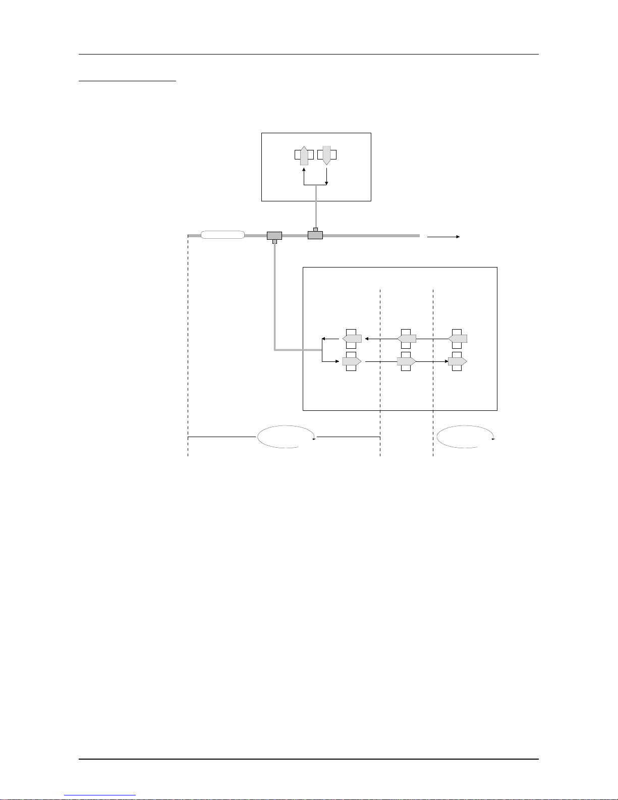
The data exchange between the DP master and the DP slave is performed
in a cycle, using send and receive buffers.
DP master
Input
Output
DP-Slave with I/O-Modules
I/O modulesCommunication
Processor
buffer receive
PROFIBUS DP
V-Bus
buffer send
V-Bus cycle
PII
PIQ
DP cycle
PII: Process image of the inputs
PIQ: Process image of the outputs
In one V-Bus cycle (i.e. VIPA backplane bus), all input data of the single
modules are collected in the PII and all output data from the PIQ are
transferred to the output modules. After the data exchange is completed,
the PII is transf erred to the sending buf fer (buf fer send) and the cont ent of
the input buffer (buffer receive) is transferred to PIQ.
In one PROFIBUS cycle, the master contacts all its slaves with a data
exchange. There the memory areas assig ned to t he PROFI BUS are written
res. read.
Afterwards the DP master transmits the data of the input area to the
receive buffer of the communication processor and the data of the send
buffer is transferred into the PROFIBUS output area.
The DP master t o DP slave data exchange on the bus is repeated cyclically
and does not depend on the V-Bus cycle.
The principles of
data transfer
operations
V-Bus cycle
DP cycle
Page 19

Manual VIPA System 100V Chapter 2 Decentral block periphery PROFIBUS DP
HB100E - SM-PB - Rev. 13/04 2-5
• Max. 125 DP slaves at one DP master - max. 32 slaves/segment
• Peripheral modules may only be plugged in or out aft er Power-Off!
• max. cable length under RS485 between two stations 1200m
(depending on the baudrate)
• max. baudrate 12 MBaud
• You must not alter the PROFIBUS address during operation
There is a wide range of diagnostic functions under PROFIBUS DP that
allow a fast error localization. The diagnostic data is broadcasted by the
bus system and summarized at the master.
As transfer medium, PRO FIBUS uses an isolated drilled twisted-pair cable
based upon the RS485 interface. The tr ansfer rate is max. 12MBaud.
The RS485-interface is working with voltage differences. Though it is less
irritable from interference than a voltage or a current interface. You are
able to configure the network as well linear as in a tree structure. Your
VIPA PROFIBUS coupler includes a 9pin slot where you connect the
PROFIBUS coupler into the PROFIBUS network as a slave.
The bus structure under RS485 allows an easy connection res.
disconnection of stations as well as starting the system step by step. Later
expansions don’t have any influence on stations that are already
integrated. The system realizes autom atically if one partner had a fail down
or is new at the network.
Every partner of the PROFIBUS network identifies itself with a certain
address. This address has to be unique at the bus system and has a value
between 0 and 99. At the VIPA PROFIBUS couplers you adjust the
address with the addressing switch at the front side.
For the VIPA PROFIBUS master you choose the address via your software
tool.
To configure the slave connections in your own config uration tool, you’ve
got all the information about your VIPA modules in form of an electronic
data sheet file.
Structure and content of this file are dictated by the PROFIBUS User
Organization (PNO) and are available there.
The GSD-file for the VIPA PROFIBUS DP Slaves is: VIPA04D4.GSD
Install this file in your conf iguration tool. Look for more inform ation in the
online help of the according tool.
Restrictions
Diagnostic
Transfer medium
Electrical system
over RS485
Addressing
GSD-file
Page 20
Chapter 2 Decentral block periphery PROFIBUS DP Manual VIPA System 100V
2-6 HB100E - SM-PB - Rev. 13/04
System overview
The System 100V from VIPA is an universal connecting link between a
fieldbus and the sensor/actuator level. In the System 100V, the System
200V technology is integrated in a compact casing.
One System 100V unit consists of a PROFIBUS DP coupler and a combination of in-/output channels and expansion clamps.
Via the integrated PROFIBUS DP coupler, your System 100V gets the
connection to PROFIBUS. The device specific data is delivered on the
included disc in an GSD (Electronic Data Sheet; in German:
Gerätestammdatei = GSD). With that file you may parameterize your
System 100V in every master projecting tool.
System overview
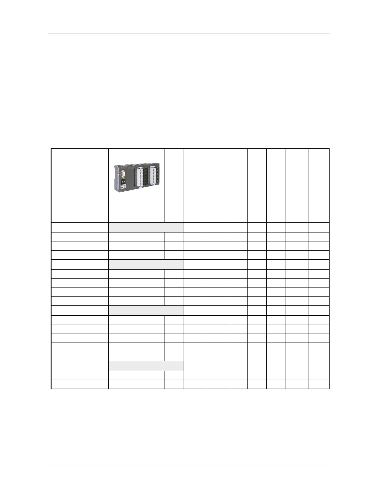
Product overview
Old order no.
New order no.
Module width
Number of input
DC 24V
Number of output
DC 24V, 1A
Number of relay output
DC 30V/AC 230V, 5A
Input data
Output data
Number of clamps
Current consumption
module
Digital input
121-4BH00 151-4PH00 4tier 16 - - 2Byte - - 55mA
121-6BH00 151-6PH00 6tier 16 - - 2Byte - 4x11 55mA
121-6BL00 151-6PL00 6tier 32 - - 4Byte - - 55mA
Digital output
122-4BH00 152-4PH00 4tier - 16 - 2Byte - - 55mA
122-6BH00 152-6PH00 6tier - 16 - 2Byte 4x11 4x11 55mA
122-6HH00 152-6PH50 6tier - - 16 2Byte - - 200mA
122-4BL00 152-6PL00 6tier - 32 - 4Byte - - 55mA
Digital in-/output
123-4BF00 153-4PF00 4tier total 8 - 1Byte 1Byte 2x11 55mA
123-4BH00 153-4PH00 4tier 8 8 - 1Byte 1Byte - 55mA
123-6BH00 153-6PH00 6tier 8 8 - 1Byte 1Byte 4x11 55mA
123-6BL00 153-6PL00 6tier 16 16 - 2Byte 2Byte - 55mA
123-6BL10 153-6PL10 6tier 24 8 - 3Byte 1Byte - 55mA
Clamps
101-4FH50 4tier - - - - - 8x11 101-6FH50 6tier - - - - - 12x11 -
Link up to
PROFIBUS
Page 21
Manual VIPA System 100V Chapter 2 Decentral block periphery PROFIBUS DP
HB100E - SM-PB - Rev. 13/04 2-7
Structure
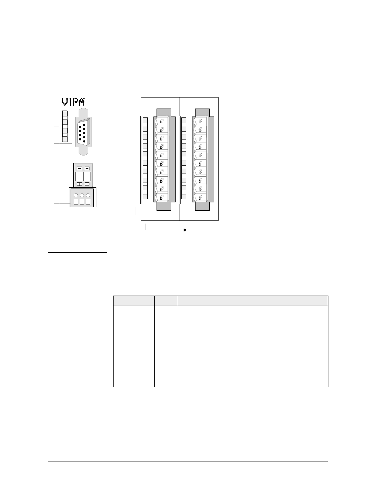
[1] LED status monitor
[2] PROFIBUS interface
[3] Address selector
[4] Power supply DC24V
1
2
3
4
PW
ER
BF
D
P
X2
34
.0
.1
.2
.3
.4
.5
.6
.7
1
2
3
4
5
6
7
8
9
I0
DC
24V
L+ M PE
X1
12
X3
.0
.1
.2
.3
.4
.5
.6
.7
1
2
3
4
5
6
7
8
9
I0
X4
5
[5] Input / output periphery
At the frontside there are 3 LEDs for bus diagnostic. The usage and the
according colors are described in the following t able:
Label Color Description
PW green Operating voltage
Signalizes applying DC 24V operating voltage
ER red Error/Diagnostic
Blinks at working diagnostic for short circuit,
overload or missing voltage supply.
Extinguishes as soon as the error is cleared.
BF red PROFIBUS bus error
Blinks during establishing communication.
Extinguishes at active communication.
Front view
Components
LEDs
PROFIBUS DP
slave
Page 22
Chapter 2 Decentral block periphery PROFIBUS DP Manual VIPA System 100V
2-8 HB100E - SM-PB - Rev. 13/04
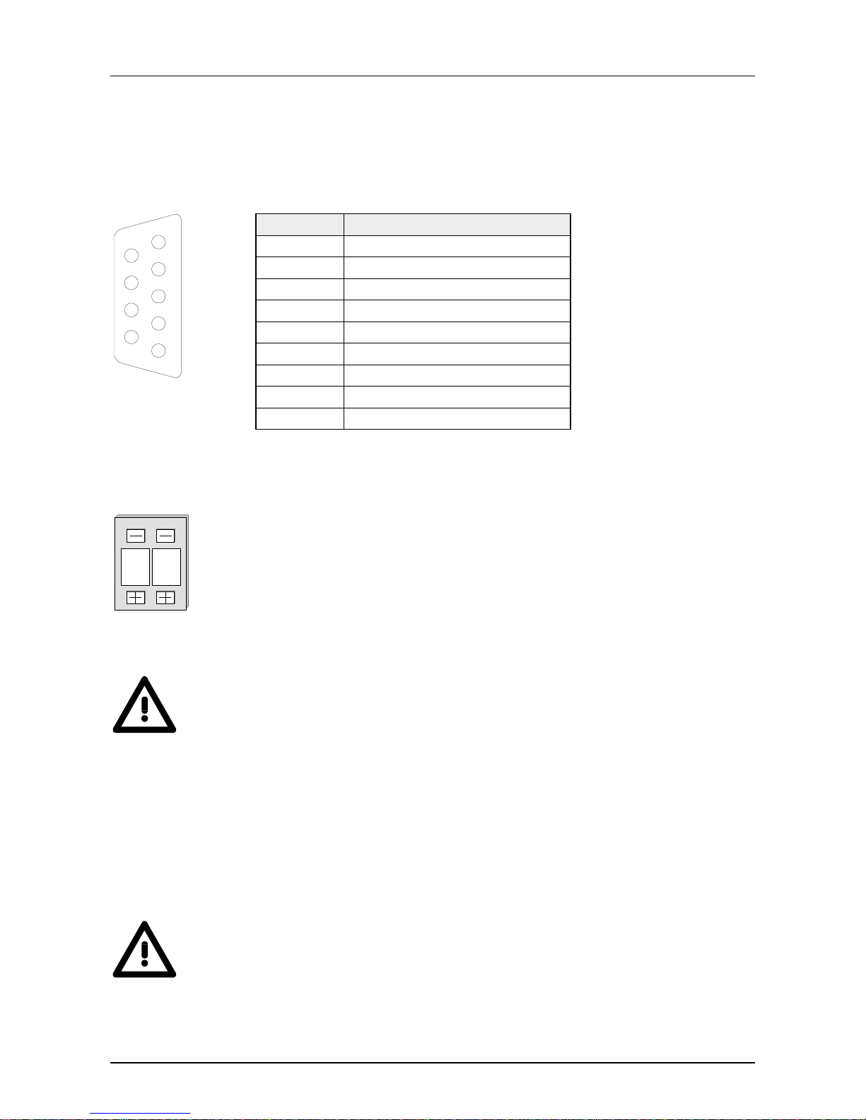
Via a 9pin RS485 interface you include your PROFIBUS slave into your
PROFIBUS.
The pin assignment of this int er face is shown in this table:
Pin Assignment
1 screen
2 n.c.
3 RxD/TxD-P (Line B)
4 RTS
5 M5V
6 P5V
7 n.c.
8 RxD/TxD-N (Line A)
5
4
3
2
1
9
8
7
6
9 n.c.
0
1
Via the address selector you choose the address that is used for the project
engineering of the DP slave.
Permissible addresses are 1 to 99. Every address has to be unique within
the bus.
The slave address has to be adjusted before switching on the bus coupler .
Attention!
You must not change the address during operation!
Every PROFIBUS slave has an integrated mains power supply. The mains
power supply has to be provided with DC 24V.
The mains power supply is protected against polarity inversion and
overvoltage.
Attention!
Please regard the correct polarit y at t he voltage supply!
RS485 interface
Address adjuster
Power supply
Page 23
Manual VIPA System 100V Chapter 2 Decentral block periphery PROFIBUS DP
HB100E - SM-PB - Rev. 13/04 2-9
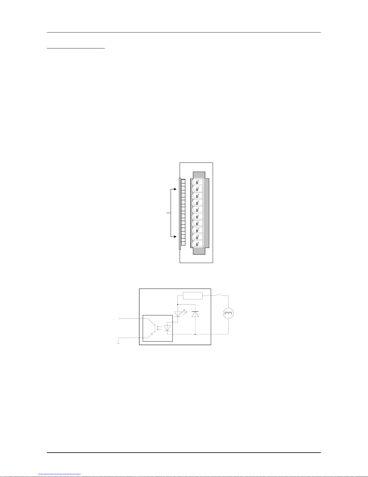
The digital input section of a System 100V module collects the binary
control signals of the process level and transmits them to the leading
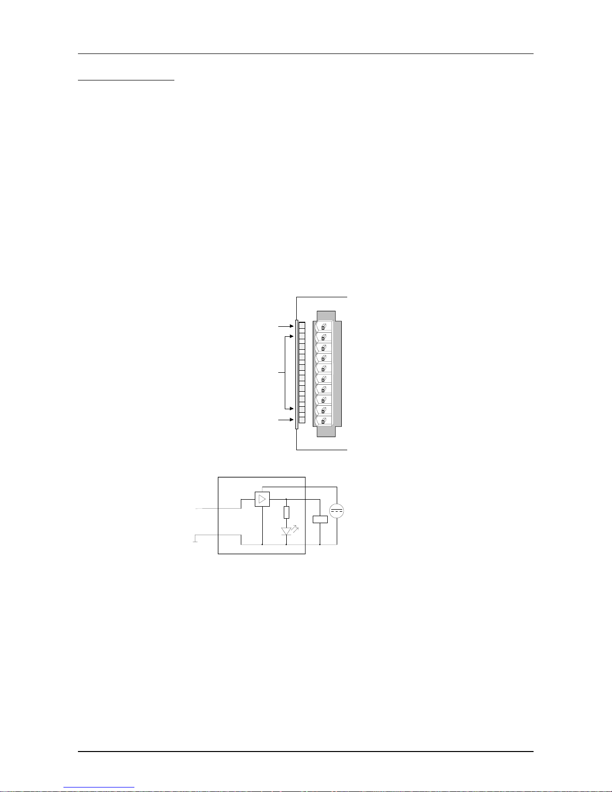
PROFIBUS.
Every input channel shows its status via a green LED with a time delay of
max. 3ms. The nominal input voltage is DC 24V. Hereby 0...5V are
recognized as signal state "0" and 15...28.8V as signal state "1". More
information about the installation of the input section is to find under
"Circuit diagrams".
LED
.0... .7
Description
LEDs (green)
I+0.0 to I+0.7
from ca. 15V on, the
signal "1" is recognized
and the according LED is
addressed
DI 8xDC24V
.0
.1
.2
.3
.4
.5
.6
.7
1
2
3
4
5
6
7
8
9
I0
Pin
1
2
3
4
5
6
7
8
9
10
Assignment
not used
Input I+0.0
Input I+0.1
Input I+0.2
Input I+0.3
Input I+0.4
Input I+0.5
Input I+0.6
Input I+0.7
Ground
DC 24V
M
internal
V-Bus
Opto coupler
LED
Input
Input section
Status monitor
Pin assignment
Schematic
diagram
Input section
Page 24
Chapter 2 Decentral block periphery PROFIBUS DP Manual VIPA System 100V
2-10 HB100E - SM-PB - Rev. 13/04
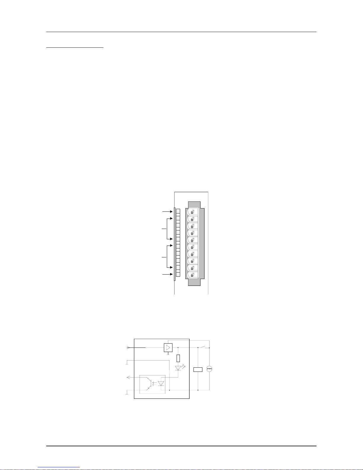
The digital output section collects the binary control signals of the leading
PROFIBUS and transmits them to the process level by means of the
outputs. The output sect ion has t o be additionally provided with DC 24V via
the front-f acing connector (see also circ uit diagram s). T he applying voltage
supply is shown via the yellow LED (L+).
Every digital output channel shows its state via a green LED. When an
output is active, the according LED is on.
At overload, overheat or short circuit, t he error LED, labeled with "F", blinks
red, a diagnostic is initialized and shown via the red ER-LED at the
PROFIBUS coupler.
LED
L+
.0... .7
F
Description
LED (yellow)
Supply voltage applied
LEDs (green)
Q+0.0 to Q+0.7
as soon as an output is
active, the according LED
is addressed
LED (red)
Error at overload, overheat
or short circuit
DO 8xDC24V 1A
L+
.0
.1
.2
.3
.4
.5
.6
.7
F
1
2
3
4
5
6
7
8
9
I0
Pin
1
2
3
4
5
6
7
8
9
10
Assignment
Supply voltage DC 24V
Output Q+0.0
Output Q+0.1
Output Q+0.2
Output Q+0.3
Output Q+0.4
Output Q+0.5
Output Q+0.6
Output Q+0.7
Supply voltage Ground
DC 24
V
LED
Output
M
internal
V-Bus
Output section
Status monitor
Pin assignment
Schematic
diagram
Output section
Page 25
Manual VIPA System 100V Chapter 2 Decentral block periphery PROFIBUS DP
HB100E - SM-PB - Rev. 13/04 2-11
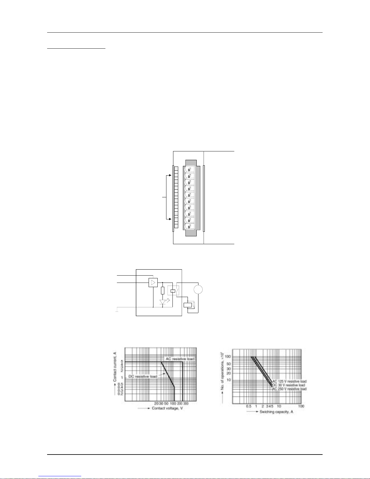
The In-/Output section has 4 I/O channels that may be used as input or as
output channels and 4 normal outputs. Every I/O channel is provided with a
diagnostic function, i.e. when an output is active the respect ive input is set
to "1". W hen a short circuit occurs at the load, the input is held at "0" and
the error is detectable by analyzing the input.
The In-/output section has to be addit ionally provided with DC 24V via the
front-facing connector (see also schem atic diagram s). T he available supply
voltage is shown via the yellow LED (L+).
Every digital in-/output channel shows its status via a green LED. At
activated in-/output, the concerning LED is on.
If an overload, overheat or short circuit occurs, the error-LED, marked with
"F", is blinking red.
LED
L+
.0... .3
.4... .7
F
Description
LED (yellow)
Supply voltage is available
LEDs (green)
I/Q+0.0 to I/Q+0.3
as soon as an I/O=1 the
according LED is
addressed
LEDs (green)
Q+0.4 to Q+0.7
as soon as an output is
active, the according LED
is addressed
LED (red)
Error at overload, overheat
or short circuits.
DIO/DO 4/4xDC24V
L+
.0
.1
.2
.3
.4
.5
.6
.7
F
1
2
3
4
5
6
7
8
9
I0
Pin
1
2
3
4
5
6
7
8
9
10
Assignment
Supply voltage DC 24V
In-/Output I/Q+0.0
In-/Output I/Q+0.1
In-/Output I/Q+0.2
In-/Output I/Q+0.3
Output Q+0.4
Output Q+0.5
Output Q+0.6
Output Q+0.7
Supply voltage ground
DC 24V
LED
Input/Output
V
-Bus
Opto coupler
Minternal
Minternal
In-/Output
section
Status monitor
pin assignment
Schematic
diagram in-/
output section
Page 26
Chapter 2 Decentral block periphery PROFIBUS DP Manual VIPA System 100V
2-12 HB100E - SM-PB - Rev. 13/04
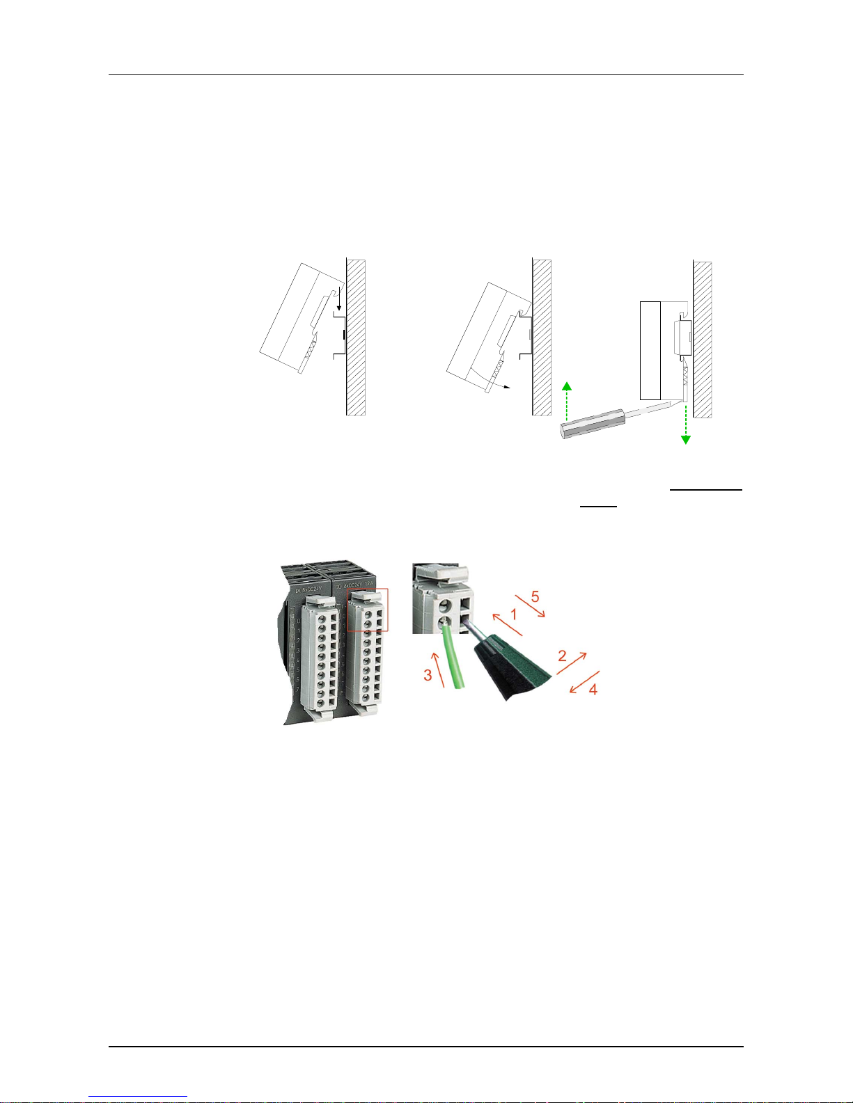
At the relay output section, you apply the load voltage on the L+ clamp (10
or 1). From a sum current of 16A on, the load voltage has to be shared
between the clamps 1 and 10.
The relay output has no LED for error s or applied load voltage. The relay
section is not able to diagnose.
LED
.0... .7
Description
LED (green)
Q+0.0 to Q+0.7
as soon as an output is
active, the according LED
is addressed
DO 8xRelais
.0
.1
.2
.3
.4
.5
.6
.7
1
2
3
4
5
6
7
8
9
I0
Pin
1
2
3
4
5
6
7
8
9
10
Assignment
Supply voltage Ca
Relay output Q+0.0
Relay output Q+0.1
Relay output Q+0.2
Relay output Q+0.3
Relay output Q+0.4
Relay output Q+0.5
Relay output Q+0.6
Relay output Q+0.7
Supply voltage Cb
Relay output module
Mintern
V-Bus
LED
AC 230V
/
DC 30
V
/
+5V
....
Note:
When using inductive
load please take an
suitable protector
(i.e. RC-combination).
Maximum toggle performance Life time
Relay output
Status monitor
Pin assignment
Schematic
diagram
Relay output
Page 27
Manual VIPA System 100V Chapter 2 Decentral block periphery PROFIBUS DP
HB100E - SM-PB - Rev. 13/04 2-13
Assembly and cabling
System 100V modules are clipped to 35mm standard norm pr ofile rails.
For the dismantling you have to pull down the locker with a screwdriver and
lift the module fr om the profile rail.
Ç Ç
Dismantling
Take a fitting screwdriver and push the cage clamp in the rectangular
opening to the back, then insert the cable into the round
opening.
The cage clamp locks securely by removing the screwdriver.
Assembly/
Dismantling
Cabling
Page 28

Chapter 2 Decentral block periphery PROFIBUS DP Manual VIPA System 100V
2-14 HB100E - SM-PB - Rev. 13/04
Link up to PROFIBUS
• The VIPA PROFIBUS DP network must have a linear structure.
• PROFIBUS DP consists of minimum one segment with at least one
master and one slave.
• A master is always used in conjunction with a CPU.
• PROFIBUS supports a max. of 125 participant s.
• A max. of 32 devices are permitted per segment.
• The maximum length of a segm ent depends on the transfer rate :
9.6 ... 187.5kBaud → 1000m
500kBaud → 400m
1.5MBaud → 200m
3 ... 12MBaud → 100m
• The network may have a maximum of 10 segments. Segments are
connected by means of repeaters. Every repeater is also seen as
participant on the network.
• All devices communicate at the same baudrate, slaves adapt automatically to the baudrate.
PROFIBUS employs a screened twisted pair cable based on RS485
interface specifications as the dat a com munication medium.
Note!
The PROFIBUS line must be terminated with ripple resist or. Please ensure
that the last participant the line is terminated by means of a terminating
resistor.
PROFIBUS in
general
PROFIBUS using
RS485
Page 29
Manual VIPA System 100V Chapter 2 Decentral block periphery PROFIBUS DP
HB100E - SM-PB - Rev. 13/04 2-15
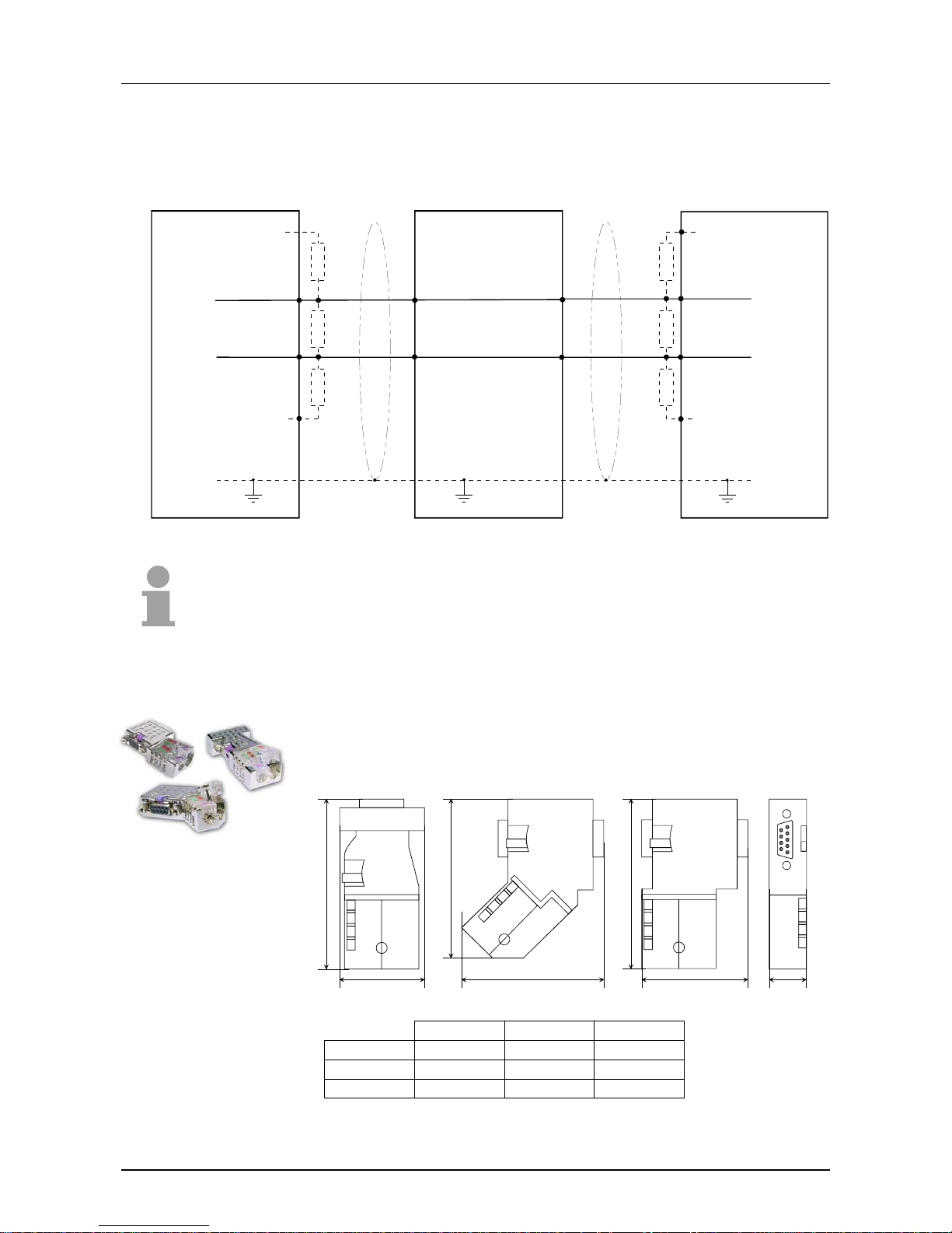
The following picture illustr ates the terminating resistors of the respective
start and end station.
RxD/TxD-P(B)
Shield
Master
Slave
3
8
3
8
P5V P5V
M5V M5V
330 330
330 330
220 220
3
8
RxD/TxD-N(A)
5
6
RxD/TxD-P(B)
RxD/TxD-N(A)
Slave
RxD/TxD-P(B)
RxD/TxD-N(A)
5
3
8
6
Shield
Shield
Note!
The PROFIBUS line has to be terminated with its ripple resistor. Please
make sure to terminate the last participants on the bus at both ends by
activating the terminating resistor .
In PROFIBUS all participants ar e wired parallel. For that purpose, the bus
cable must be feed-through.
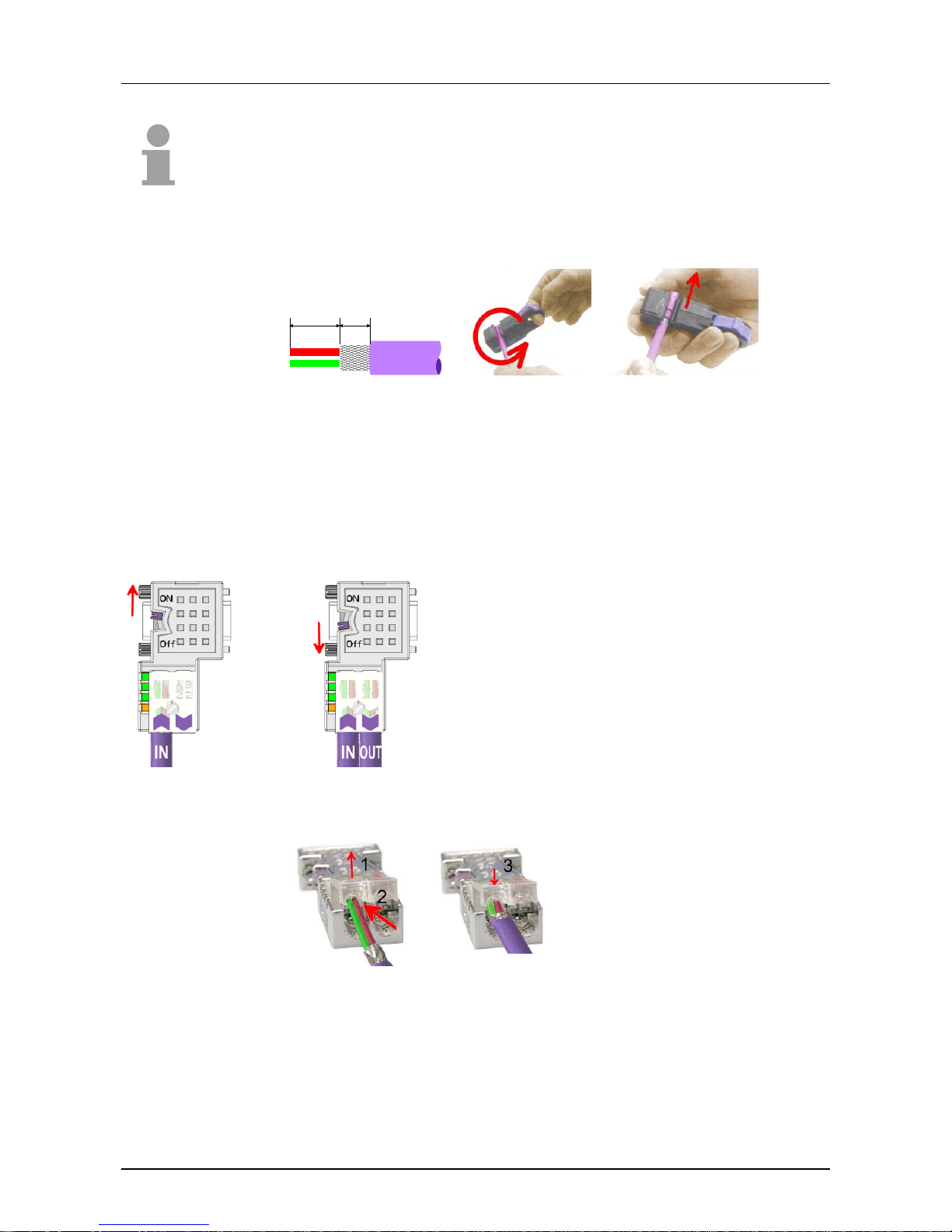
Via the order number VIPA 972-0DP10 you may order the bus connector
"EasyConn". This is a bus connector with switchable terminating resistor
and integrated bus diagnostic.
C
A
B
90°
A
B
0°
B
A
45°
0° 45° 90°
A 64 61 66
B 34 53 40
C 15.8 15.8 15.8
in mm
Bus connection
EasyConn
bus connector
Page 30
Chapter 2 Decentral block periphery PROFIBUS DP Manual VIPA System 100V
2-16 HB100E - SM-PB - Rev. 13/04
Note!
To connect this EasyConn plug , please use the st andard PROFIBUS cable
type A (EN50170). Starting with release 5 you also can use highly flexible
bus cable: Lapp Kabel order no.: 2170222, 2170822, 2170322.
With the or der no. 905-6AA00 VIPA off ers the "EasyStrip" de-isolating tool
that makes the connection of the EasyConn much easier .
11 6
Dimensions in mm
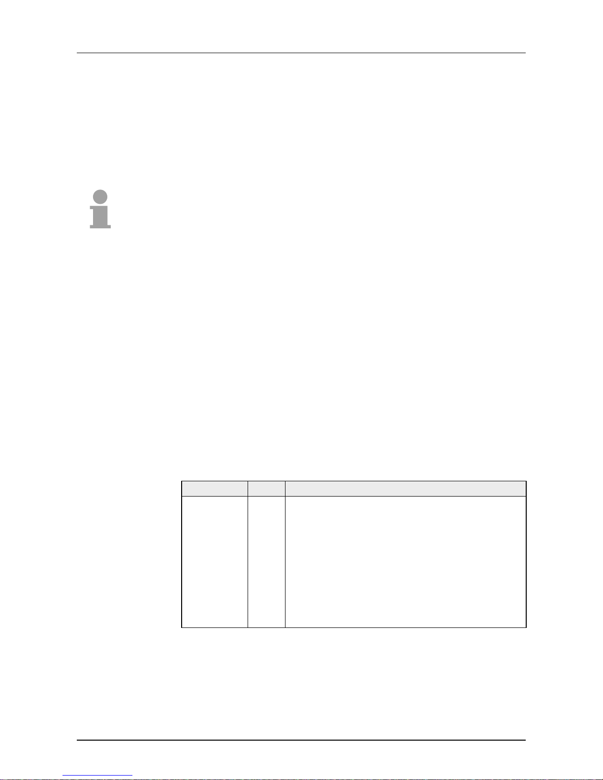
The "EasyConn" bus connector is provided with a switch that is used to
activate a terminating resistor.
1./last
bus participant
further
participants
Attention!
The terminating resistor is only effec-
tive, if the connector is installed at a bus
participant and the bus participant is
connected to a power supply.
Note!
A complete description of installation
and deployment of the terminating
resistors is delivered with the connector.
• Loosen the screw.
• Lift contact-cover.
• Insert both wires into the ducts
provided (watch for the correct
line color as below!)
• Please take care not to cause a
short circuit between screen and
data lines!
• Close the contact cover.
• Tighten screw
(max. tightening torque 4Nm).
The green line must be connected to A, the red line to B!
Termination with
"EasyConn"
Wiring
Assembly
Please note:
Page 31
Manual VIPA System 100V Chapter 2 Decentral block periphery PROFIBUS DP
HB100E - SM-PB - Rev. 13/04 2-17
Commissioning
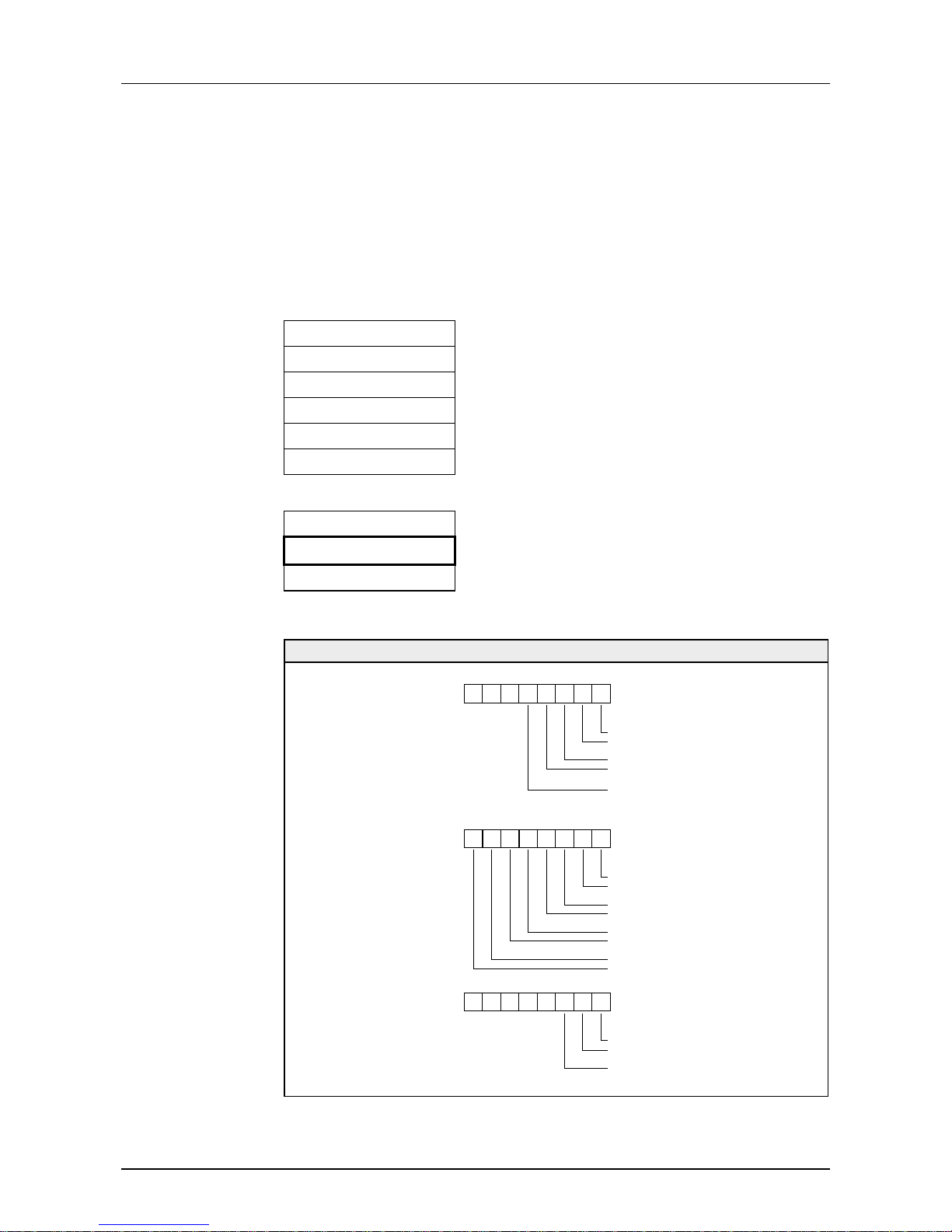
Every participant at the PROFIBUS identifies itself with an address. This
address has to be unique in this bus system and may cover the range
between 0 and 99 at the System 100V.
At the System 100V you adjust the PROFIBUS address via the address
adjuster at the module front side.
Note!
Please make sure, that you use the same address in your conf iguration!
On the included disc you will find the G SD-file of the System 100V in the
GSD-folder. Copy it to the G SD- dir ectory of your configuration tool.
When using the configuration tool WinNCS from VIPA together with an
IM208-Master from VIPA, the GSD- file is part of WinNCS.
• Install your System 100V at the profile r ail.
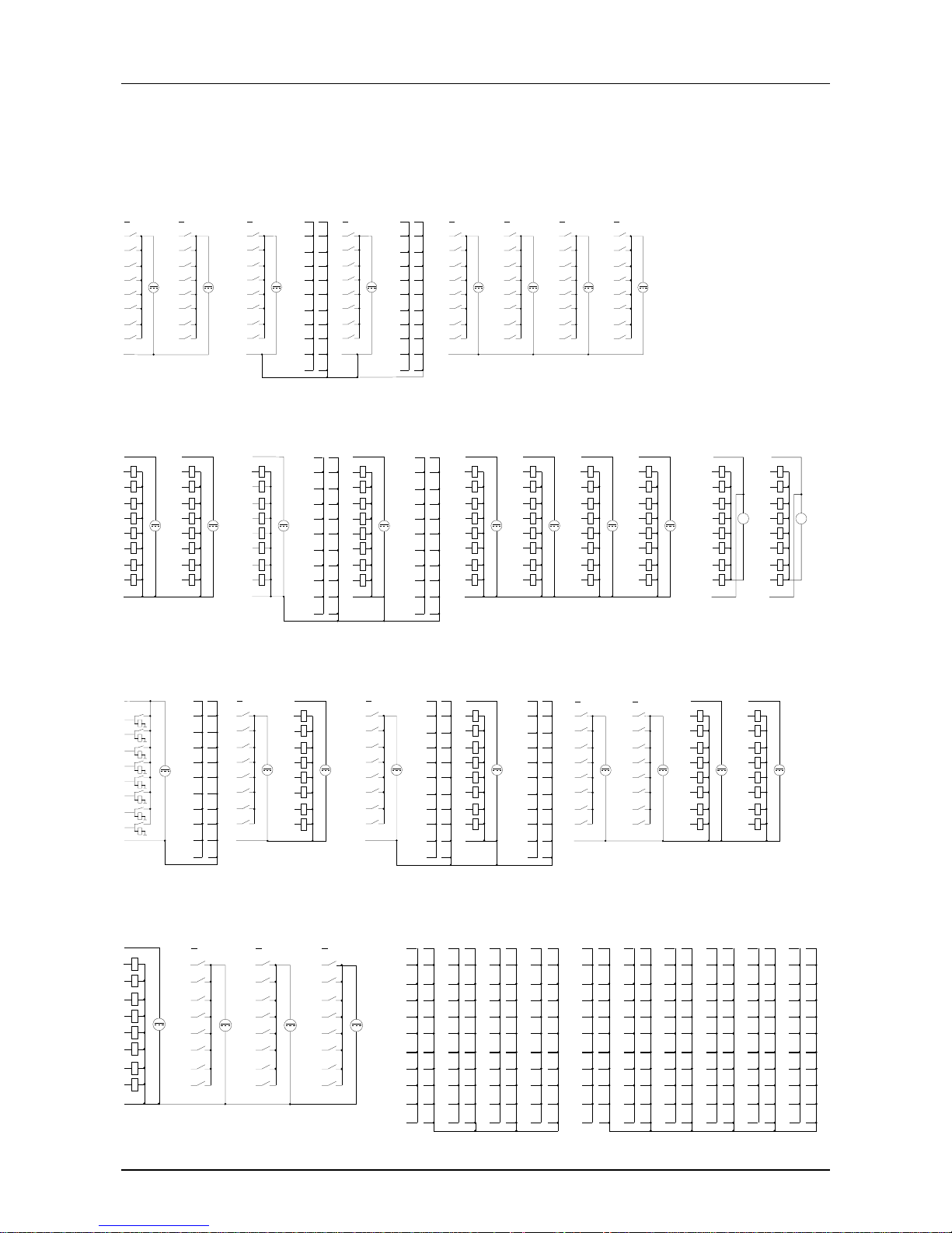
• Cable your System 100V like shown in the circuit diagrams. Please
regard, that the output unit s need an exter nal voltage supply.
• Choose the PROFIBUS address at the front side and transfer it into your
project engineering.
• Configure your PROFIBUS and transfer your project into the master.
• For further commissioning please proceed the description of your
master system.
At the front side there are 3 LEDs, serving the bus diagnostic. The usage
and the according colors of this diag nost ic LEDs ar e shown in the table:
Label Color Description
PW green Operating voltage
Signalizes applying DC 24V operating voltage
ER red Error/Diagnostics
Blink at waiting diagnostic because of a short
circuit, an overload or missing voltage supply.
Extinguishes as soon as the error is cleared.
BF yellow PROFIBUS bus error
Blinks during the communication star t. Extinguishes
as soon as the bus communication is established.
PROFIBUS
addressing
Project
engineering
Commissioning
LEDs PROFIBUS
coupler unit
Page 32
Chapter 2 Decentral block periphery PROFIBUS DP Manual VIPA System 100V
2-18 HB100E - SM-PB - Rev. 13/04
Diagnostic
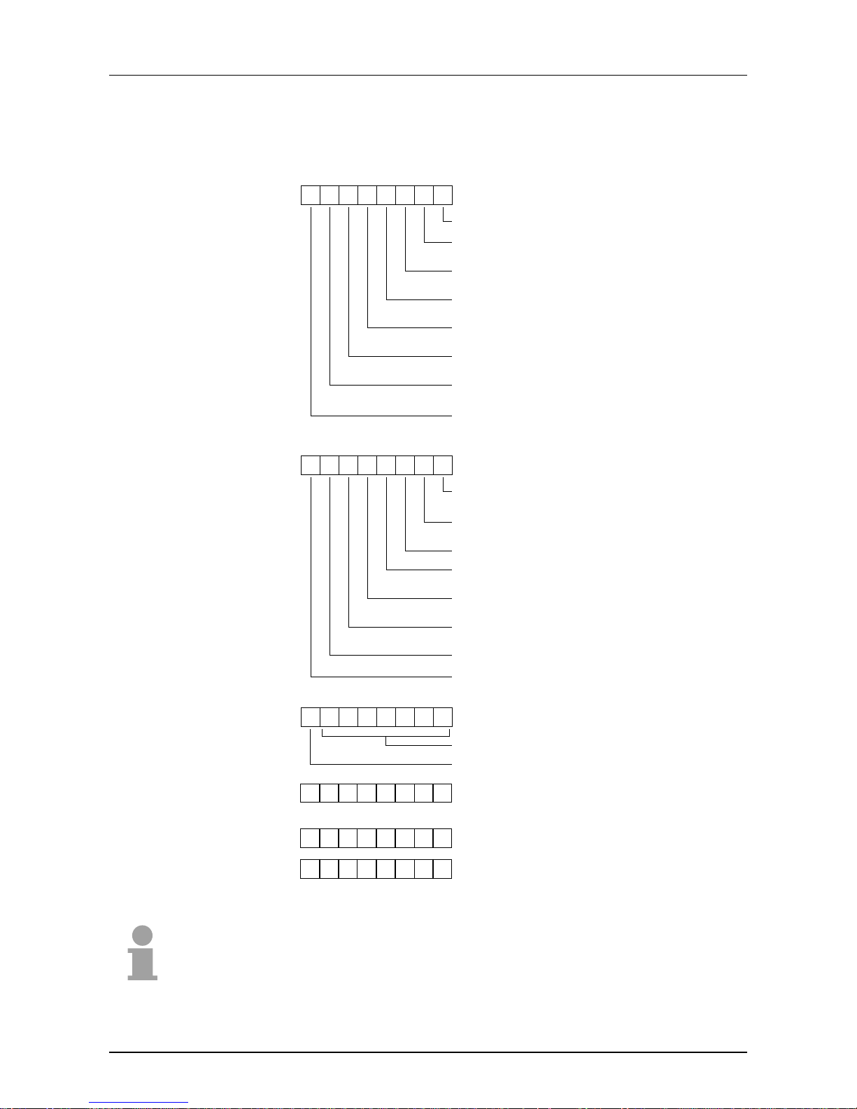
At request from t he master or at an error event, the integrated PROFIBUS
coupler sends a 13Byte diagnostic telegram. At this time only the digital
output units are diagnosable.
The diagnostic telegram has the following structure:
Norm diagnostic data
Byte 0 Station state 1
Byte 1 Station state 2
Byte 2 Station state 3
Byte 3 Master address
Byte 4 Ident no (low)
Byte 5 Ident no (high)
Device related diagnostic data
Byte 6 Diagnostic header fixed at 07h
Byte 7 Diagnostic Byte of the periphery
Byte 8 ... Byte 12 00h reserved
Module Structure Diagnostic-Byte 7
152-4PH00
152-6PH00
153-6PL00
0
7 0 Bit No.
0 0
Error OB0 Output 0...3
Error OB0 Output 4...7
Error OB1 Output 0...3
Error OB1 Output 4...7
Load voltage
0 = off
1 = on
Byte 7
152-6PL00
7 0 Bit No.
Error OB0 Output 0. ..3
Error OB0 Output 4. ..7
Error OB1 Output 0. ..3
Error OB1 Output 4. ..7
Error OB2 Output 0. ..3
Error OB2 Output 4. ..7
Error OB3 Output 0. ..3
Error OB3 Output 4. ..7
Byte 7
153-4PF00
153-4PH00
153-6PH00
153-6PL10
0
7 0 Bit No.
0 0
Error OB0 Output 0...3
Error OB0 Output 4...7
Load voltage
0 = off
1 = on
Byte 7
00
13Byte
Diagnostic data
Overview
Diagnostic Byte 7
Page 33
Manual VIPA System 100V Chapter 2 Decentral block periphery PROFIBUS DP
HB100E - SM-PB - Rev. 13/04 2-19
More information about the structure of t he norm diagnost ic data are to find
in the PROFIBUS Norm papers. These are available at the "PROFIBUS
Nutzer Organisation" (PROFIBUS User Org).
7 0 Bit No.
Diagnostic station does not exist (sets master)
Diag.station_not_ready
Slave not ready for data exchange
Diag.cfg_fault
Configuration data do not match
Diag.ext_diag
Slave has external diagnostic data
Diag.not_supported
Slave does not support requested function
Diag.invalid_slave_response
(sets slave to 0)
Diag.prm_fault
Falsely set parameter (Ident. No. etc.)
Diag.master_lock (sets master)
Slave's parameters set by different master
Byte 0
Byte 3
Diag.master_add
Master address after setting parameters
FFh without parameter setting
7 0 Bit No.
Diag.prm_req
Slave's parameters must be reset
Diag.stat_diag
Statistical diagnosis
Set to 1
Diag.wd_on
Response monitoring active
Diag.freeze_mode
Freeze command received
Sync_mode
Sync command received
reserverd
Diag.deactivated (sets master)
Byte 1
7 0 Bit No.
reserverd
Diag.ext_overflow
Byte 2
Byte 4
Identity number "high "byte"
Byte 5
Identity num b e r "low byte"
Note!
The Byte 3 of the norm diagnostic data contains the address of the
PROFIBUS master that paramet er izes the System 100V m odule.
When an FFh is entered her e, the according System 100V module is not
parameterized in the master.
Norm
diagnostic data
(Byte 0 ... Byte 5)
Page 34
Chapter 2 Decentral block periphery PROFIBUS DP Manual VIPA System 100V
2-20 HB100E - SM-PB - Rev. 13/04
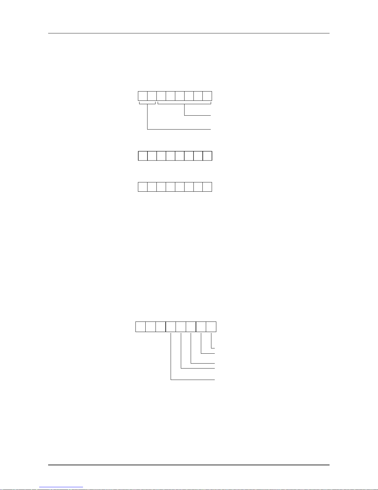
The device related diagnostic data contain detailed inf ormation about the
periphery of the System 100V.
The device related diagnostic data have the following structur e:
0
7 0 Bit No.
0 0 0 0 1 1 1
Length of device-related diagnosis
000111 Length = 7 byte (set)
Code for device-related diagnosis
00 Code = 00 (set)
Byte 6
7 0 Bit No.
Diagnostic byte
Byte 7
Byte 8
.
.
.
Byte 12
00h reserved
Every output unit is addressed via an output byte (AB) . In case of an er ror,
the unit occupies 2 diagnostic bits in ascending series start ing at Bit 0, one
for Low-AB (output 0...3) and one for High-AB (output 4...7).
For not all modules occupy all bits, the next free bit is used for monitoring
the applying load voltage "diagnostic load voltage on".
Example
The module 153-6PL00 (DI 16xDC 24V / DO 16xDC 24V) has t he f ollowing
diagnostic byte:
0
7 0 Bit no.
0 0
Error OB0 Output 0...3
Error OB0 Output 4...7
Error OB1 Output 0...3
Error OB1 Output 4...7
Load voltage
0 = off
1 = on
Byte 7
Device related
diagnostic data
(Byte 6 ... Byte 12)
Diagnostic Byte 7
Page 35
Manual VIPA System 100V Chapter 2 Decentral block periphery PROFIBUS DP
HB100E - SM-PB - Rev. 13/04 2-21
Circuit diagrams
Digital input
DC
24V
M
1
2
3
4
5
6
7
8
9
10
DC
24V
M
1
2
3
4
5
6
7
8
9
10
VIPA 151-4PH00
DC
24V
M
1
2
3
4
5
6
7
8
9
10
VIPA 151-6PH00
X4
1
2
3
4
5
6
7
8
9
10
11
X4M
1
2
3
4
5
6
7
8
9
10
11
DC
24V
M
1
2
3
4
5
6
7
8
9
10
X6
1
2
3
4
5
6
7
8
9
10
11
X6M
1
2
3
4
5
6
7
8
9
10
11
DC
24V
M
1
2
3
4
5
6
7
8
9
10
DC
24V
M
1
2
3
4
5
6
7
8
9
10
VIPA 151-6PL00
DC
24V
M
1
2
3
4
5
6
7
8
9
10
DC
24V
M
1
2
3
4
5
6
7
8
9
10
X3
X4 X3
X5
X3
X4
X5
X6
Digital output Relay output
VIPA 152-4PH00
DC
24V
M
1
2
3
4
5
6
7
8
9
10
1L+
DC
24V
M
1
2
3
4
5
6
7
8
9
10
2L+
VIPA 152-6PH00
X4
1
2
3
4
5
6
7
8
9
10
11
X4M
1
2
3
4
5
6
7
8
9
10
11
X6
1
2
3
4
5
6
7
8
9
10
11
X6M
1
2
3
4
5
6
7
8
9
10
11
DC
24V
M
1
2
3
4
5
6
7
8
9
10
1L+
DC
24V
M
1
2
3
4
5
6
7
8
9
10
2L+
VIPA 152-6PL00
DC
24V
M
1
2
3
4
5
6
7
8
9
10
1L+
DC
24V
M
1
2
3
4
5
6
7
8
9
10
2L+
DC
24V
M
1
2
3
4
5
6
7
8
9
10
3L+
DC
24V
M
1
2
3
4
5
6
7
8
9
10
4L+
VIPA 152-6PH50
AC
230V
DC
30V
1Ca
1
2
3
4
5
6
7
8
9
10
1Ca
1Cb
AC
230V
DC
30V
1
2
3
4
5
6
7
8
9
10
2Ca
2Cb
X3
X4 X3
X5 X3
X4
X5
X6
X3 X4
2Ca
Digital in-/output
VIPA 153-4PF00
1
10
M
L+
DC
24V
2
3
4
5
6
7
8
9
X4
1
2
3
4
5
6
7
8
9
10
11
X4M
1
2
3
4
5
6
7
8
9
10
11
VIPA 153-4PH00
DC
24V
M
1
2
3
4
5
6
7
8
9
10
L+
DC
24V
M
1
2
3
4
5
6
7
8
9
10
VIPA 153-6PH00
X4
1
2
3
4
5
6
7
8
9
10
11
X4M
1
2
3
4
5
6
7
8
9
10
11
X6
1
2
3
4
5
6
7
8
9
10
11
X6M
1
2
3
4
5
6
7
8
9
10
11
DC
24V
M
1
2
3
4
5
6
7
8
9
10
L+
DC
24V
M
1
2
3
4
5
6
7
8
9
10
DC
24V
M
1
2
3
4
5
6
7
8
9
10
DC
24V
M
1
2
3
4
5
6
7
8
9
10
VIPA 153-6PL00
DC
24V
M
1
2
3
4
5
6
7
8
9
10
1L+
DC
24V
M
1
2
3
4
5
6
7
8
9
10
2L+
X3 X3
X4
X3
X5 X3 X4
X5
X6
Clamps
DC
24V
M
1
2
3
4
5
6
7
8
9
10
VIPA 153-6PL10
DC
24V
M
1
2
3
4
5
6
7
8
9
10
L+
DC
24V
M
1
2
3
4
5
6
7
8
9
10
DC
24V
M
1
2
3
4
5
6
7
8
9
10
VIPA 101-4FH50
X1
1
2
3
4
5
6
7
8
9
10
11
X1M
1
2
3
4
5
6
7
8
9
10
11
X2
1
2
3
4
5
6
7
8
9
10
11
X2M
1
2
3
4
5
6
7
8
9
10
11
X3
1
2
3
4
5
6
7
8
9
10
11
X3M
1
2
3
4
5
6
7
8
9
10
11
X4
1
2
3
4
5
6
7
8
9
10
11
X4M
1
2
3
4
5
6
7
8
9
10
11
VIPA 101-6FH50
1
2
3
4
5
6
7
8
9
10
11
1
2
3
4
5
6
7
8
9
10
11
1
2
3
4
5
6
7
8
9
10
11
1
2
3
4
5
6
7
8
9
10
11
1
2
3
4
5
6
7
8
9
10
11
1
2
3
4
5
6
7
8
9
10
11
1
2
3
4
5
6
7
8
9
10
11
1
2
3
4
5
6
7
8
9
10
11
1
2
3
4
5
6
7
8
9
10
11
1
2
3
4
5
6
7
8
9
10
11
1
2
3
4
5
6
7
8
9
10
11
1
2
3
4
5
6
7
8
9
10
11
X3
X4 X5 X6
X1 X1M
X2MX2 X3
X4
X5
X3M
X4M
X5M X6MX6
Page 36
Chapter 2 Decentral block periphery PROFIBUS DP Manual VIPA System 100V
2-22 HB100E - SM-PB - Rev. 13/04
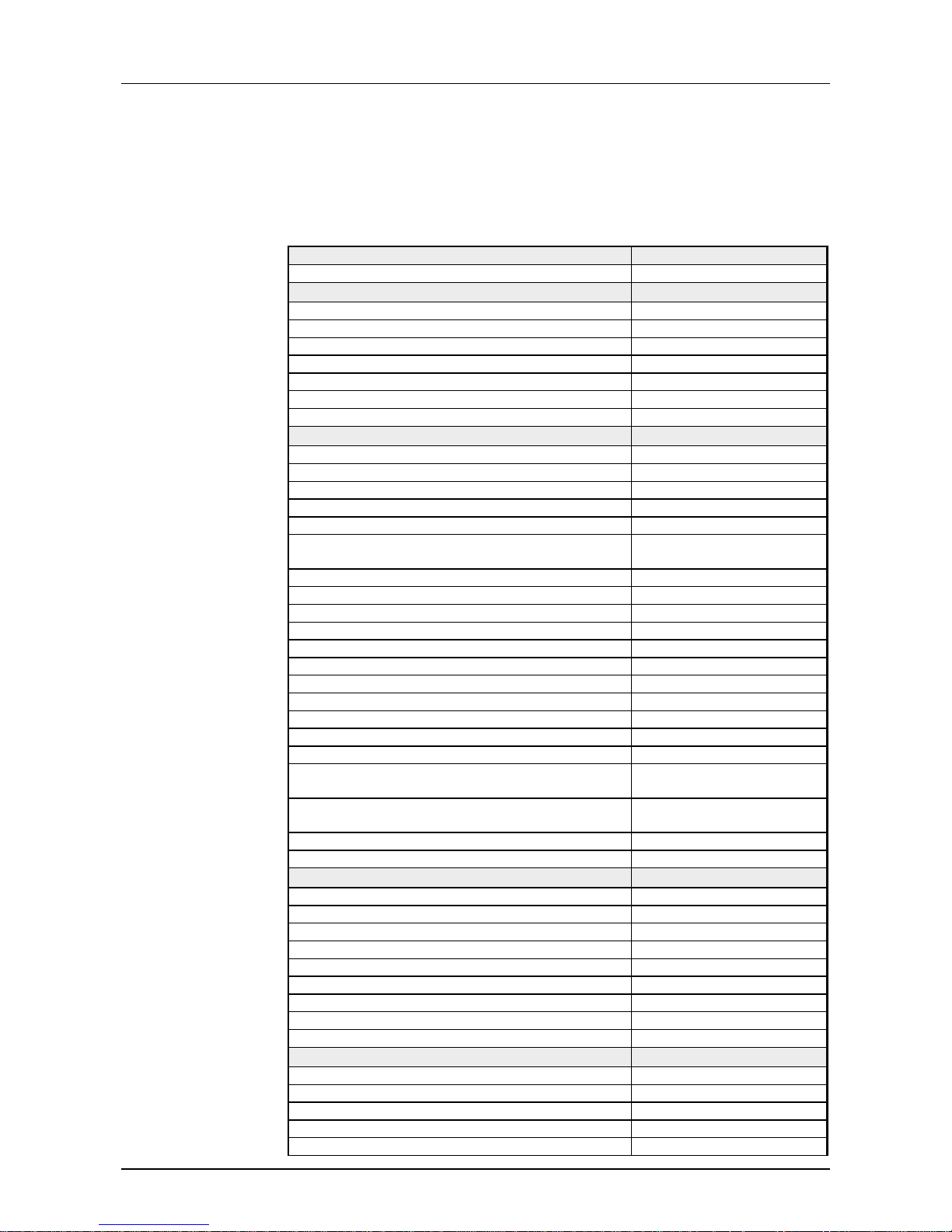
Technical Data
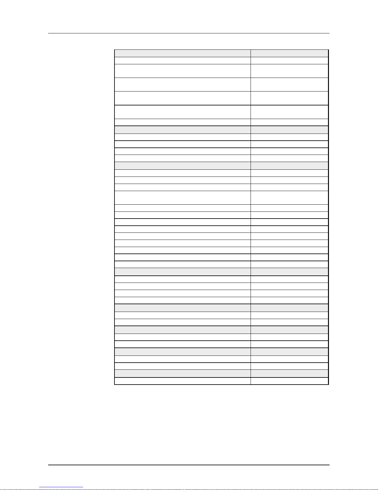
PROFIBUS DP slave with digital input
Order no. 151-4PH00
Type SM 151
Technical data power supply
Power supply (rated value) DC 24 V
Power supply (permitted range) DC 20.4...28.8 V
Reverse polarity protection
9
Current consumption (no-load operation) Current consumption (rated value) 55 mA
Inrush current 40 A
I²t 0.15 A²s
Technical data digital inputs
Number of inputs 16
Cable length, shielded 1000 m
Cable length, unshielded 600 m
Rated load voltage DC 24 V
Reverse polarity protection of rated load voltage Current consumption from load voltage L+ (without
load)
-
Rated value DC 24 V
Input voltage for signal "0" DC 0...5 V
Input voltage for signal "1" DC 15...28.8 V
Input voltage hysteresis Frequency range Input resistance Input current for signal "1" 7 mA
Connection of Two-Wire-BEROs possible
9
Max. permissible BERO quiescent current 1.5 mA
Input delay of "0" to "1" 3 ms
Input delay of "1" to "0" 3 ms
Number of simultaneously utilizable inputs
horizontal configuration
16
Number of simultaneously utilizable inputs vertical
configuration
16
Input characteristic curve IEC 61131-2, type 1
Initial data size 2 Byte
Status information, alarms, diagnostics
Status display green LED per channel
Interrupts no
Process alarm no
Diagnostic interrupt no
Diagnostic functions no
Diagnostics information read-out possible
Supply voltage display yes
Group error display red SF LED
Channel error display none
Isolation
Between channels Between channels of groups to Between channels and backplane bus Between channels and power supply Max. potential difference between circuits -
SM 151
151-4PH00
Page 37
Manual VIPA System 100V Chapter 2 Decentral block periphery PROFIBUS DP
HB100E - SM-PB - Rev. 13/04 2-23
Order no. 151-4PH00
Max. potential difference between inputs (Ucm) Max. potential difference between Mana and
Mintern (Uiso)
-
Max. potential difference between inputs and Mana
(Ucm)
-
Max. potential difference between inputs and
Mintern (Uiso)
-
Max. potential difference between Mintern and
outputs
-
Insulation tested with DC 500 V
Hardware configuration
Racks, max. Modules per rack, max. Number of digital modules, max. Number of analog modules, max. -
Communication
Fieldbus PROFIBUS-DP to EN 50170
Type of interface RS485
Connector Sub-D, 9-pin, female
Topology Linear bus with bus
termination at both ends
Electrically isolated
9
Number of participants, max. 125
Node addresses 1 - 99
Transmission speed, min. 9.6 kbit/s
Transmission speed, max. 12 Mbit/s
Address range inputs, max. 2 Byte
Address range outputs, max. 0 Byte
Number of TxPDOs, max. Number of RxPDOs, max. -
Datasizes
Input bytes 1
Output bytes 0
Parameter bytes 7 + 5
Diagnostic bytes 0
Housing
Material PPE / PA 6.6
Mounting Profile rail 35 mm
Mechanical data
Dimensions (WxHxD) 101.6 x 76 x 48 mm
Weight 217 g
Environmental conditions
Operating temperature 0 °C to 60 °C
Storage temperature -25 °C to 70 °C
Certifications
UL508 certification yes
Page 38
Chapter 2 Decentral block periphery PROFIBUS DP Manual VIPA System 100V
2-24 HB100E - SM-PB - Rev. 13/04
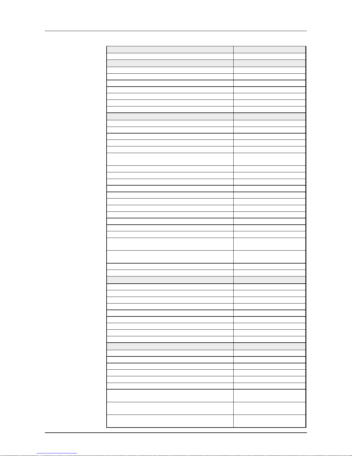
Order no. 151-6PH00
Type SM 151
Technical data power supply
Power supply (rated value) DC 24 V
Power supply (permitted range) DC 20.4...28.8 V
Reverse polarity protection
9
Current consumption (no-load operation) Current consumption (rated value) 55 mA
Inrush current 40 A
I²t 0.15 A²s
Technical data digital inputs
Number of inputs 16
Cable length, shielded 1000 m
Cable length, unshielded 600 m
Rated load voltage DC 24 V
Reverse polarity protection of rated load voltage Current consumption from load voltage L+ (without
load)
-
Rated value DC 24 V
Input voltage for signal "0" DC 0...5 V
Input voltage for signal "1" DC 15...28.8 V
Input voltage hysteresis Frequency range Input resistance Input current for signal "1" 7 mA
Connection of Two-Wire-BEROs possible
9
Max. permissible BERO quiescent current 1.5 mA
Input delay of "0" to "1" 3 ms
Input delay of "1" to "0" 3 ms
Number of simultaneously utilizable inputs
horizontal configuration
16
Number of simultaneously utilizable inputs vertical
configuration
16
Input characteristic curve IEC 61131-2, type 1
Initial data size 2 Byte
Status information, alarms, diagnostics
Status display green LED per channel
Interrupts no
Process alarm no
Diagnostic interrupt no
Diagnostic functions no
Diagnostics information read-out possible
Supply voltage display yes
Group error display red SF LED
Channel error display none
Isolation
Between channels Between channels of groups to Between channels and backplane bus Between channels and power supply Max. potential difference between circuits Max. potential difference between inputs (Ucm) Max. potential difference between Mana and
Mintern (Uiso)
-
Max. potential difference between inputs and Mana
(Ucm)
-
Max. potential difference between inputs and
Mintern (Uiso)
-
151-6PH00
Page 39
Manual VIPA System 100V Chapter 2 Decentral block periphery PROFIBUS DP
HB100E - SM-PB - Rev. 13/04 2-25
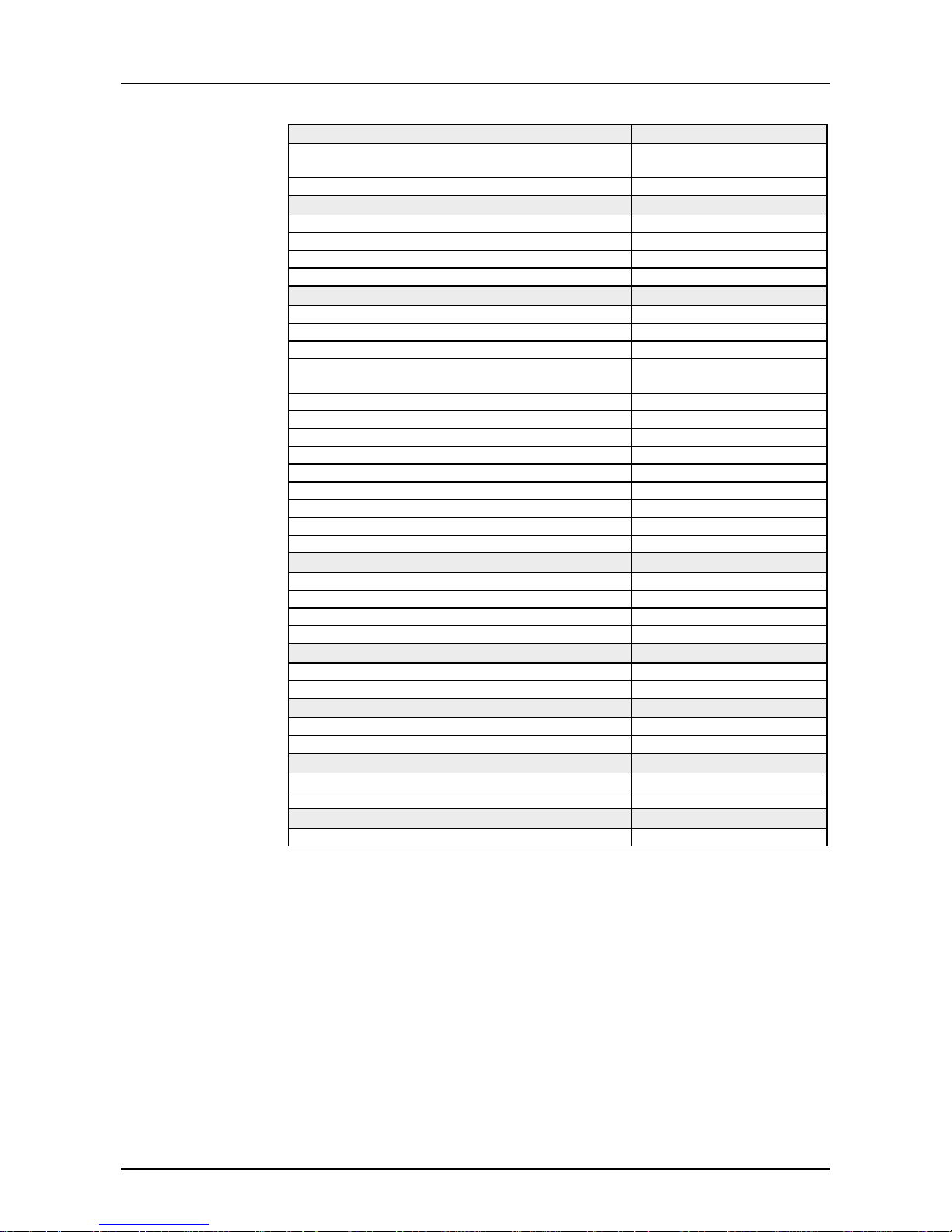
Order no. 151-6PH00
Max. potential difference between Mintern and
outputs
-
Insulation tested with DC 500 V
Hardware configuration
Racks, max. Modules per rack, max. Number of digital modules, max. Number of analog modules, max. -
Communication
Fieldbus PROFIBUS-DP to EN 50170
Type of interface RS485
Connector Sub-D, 9-pin, female
Topology Linear bus with bus
termination at both ends
Electrically isolated
9
Number of participants, max. 125
Node addresses 1 - 99
Transmission speed, min. 9.6 kbit/s
Transmission speed, max. 12 Mbit/s
Address range inputs, max. 2 Byte
Address range outputs, max. 0 Byte
Number of TxPDOs, max. Number of RxPDOs, max. -
Datasizes
Input bytes 2
Output bytes 0
Parameter bytes 7 + 5
Diagnostic bytes 0
Housing
Material PPE / PA 6.6
Mounting Profile rail 35 mm
Mechanical data
Dimensions (WxHxD) 152.4 x 76 x 48 mm
Weight 288 g
Environmental conditions
Operating temperature 0 °C to 60 °C
Storage temperature -25 °C to 70 °C
Certifications
UL508 certification yes
Page 40
Chapter 2 Decentral block periphery PROFIBUS DP Manual VIPA System 100V
2-26 HB100E - SM-PB - Rev. 13/04
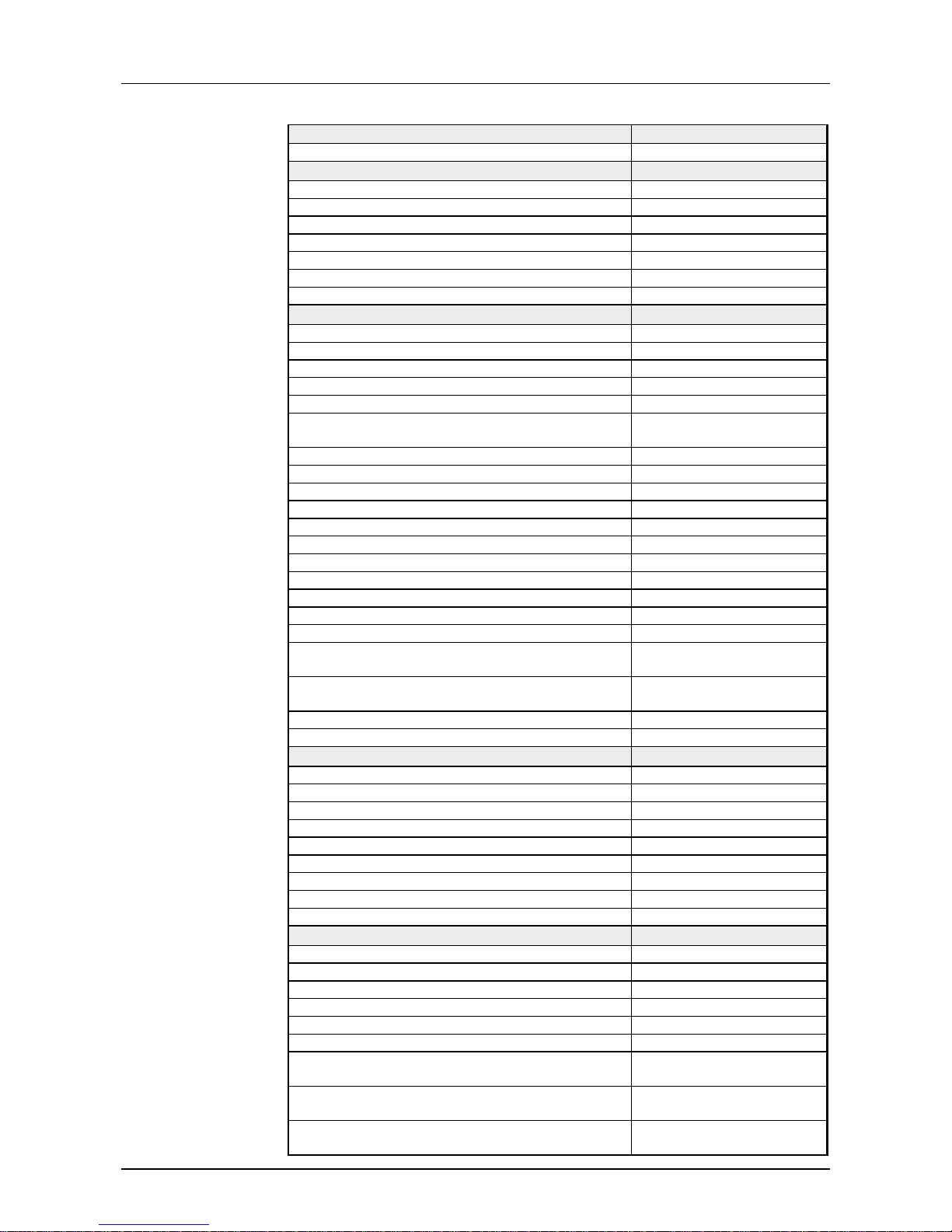
Order no. 151-6PL00
Type SM 151
Technical data power supply
Power supply (rated value) DC 24 V
Power supply (permitted range) DC 20.4...28.8 V
Reverse polarity protection
9
Current consumption (no-load operation) Current consumption (rated value) 55 mA
Inrush current 40 A
I²t 0.15 A²s
Technical data digital inputs
Number of inputs 32
Cable length, shielded 1000 m
Cable length, unshielded 600 m
Rated load voltage DC 24 V
Reverse polarity protection of rated load voltage Current consumption from load voltage L+ (without
load)
-
Rated value DC 24 V
Input voltage for signal "0" DC 0...5 V
Input voltage for signal "1" DC 15...28.8 V
Input voltage hysteresis Frequency range Input resistance Input current for signal "1" 7 mA
Connection of Two-Wire-BEROs possible
9
Max. permissible BERO quiescent current 1.5 mA
Input delay of "0" to "1" 3 ms
Input delay of "1" to "0" 3 ms
Number of simultaneously utilizable inputs
horizontal configuration
32
Number of simultaneously utilizable inputs vertical
configuration
32
Input characteristic curve IEC 61131-2, type 1
Initial data size 4 Byte
Status information, alarms, diagnostics
Status display green LED per channel
Interrupts no
Process alarm no
Diagnostic interrupt no
Diagnostic functions no
Diagnostics information read-out possible
Supply voltage display yes
Group error display red SF LED
Channel error display none
Isolation
Between channels Between channels of groups to Between channels and backplane bus Between channels and power supply Max. potential difference between circuits Max. potential difference between inputs (Ucm) Max. potential difference between Mana and
Mintern (Uiso)
-
Max. potential difference between inputs and Mana
(Ucm)
-
Max. potential difference between inputs and
Mintern (Uiso)
-
151-6PL00
Page 41
Manual VIPA System 100V Chapter 2 Decentral block periphery PROFIBUS DP
HB100E - SM-PB - Rev. 13/04 2-27
Order no. 151-6PL00
Max. potential difference between Mintern and
outputs
-
Insulation tested with DC 500 V
Hardware configuration
Racks, max. Modules per rack, max. Number of digital modules, max. Number of analog modules, max. -
Communication
Fieldbus PROFIBUS-DP to EN 50170
Type of interface RS485
Connector Sub-D, 9-pin, female
Topology Linear bus with bus
termination at both ends
Electrically isolated
9
Number of participants, max. 125
Node addresses 1 - 99
Transmission speed, min. 9.6 kbit/s
Transmission speed, max. 12 Mbit/s
Address range inputs, max. 4 Byte
Address range outputs, max. 0 Byte
Number of TxPDOs, max. Number of RxPDOs, max. -
Datasizes
Input bytes 4
Output bytes 0
Parameter bytes 7 + 5
Diagnostic bytes 0
Housing
Material PPE / PA 6.6
Mounting Profile rail 35 mm
Mechanical data
Dimensions (WxHxD) 152.4 x 76 x 48 mm
Weight 260 g
Environmental conditions
Operating temperature 0 °C to 60 °C
Storage temperature -25 °C to 70 °C
Certifications
UL508 certification yes
Page 42
Chapter 2 Decentral block periphery PROFIBUS DP Manual VIPA System 100V
2-28 HB100E - SM-PB - Rev. 13/04
PROFIBUS DP slave with digital output
Order no. 152-4PH00
Type SM 152
Technical data power supply
Power supply (rated value) DC 24 V
Power supply (permitted range) DC 20.4...28.8 V
Reverse polarity protection
9
Current consumption (no-load operation) Current consumption (rated value) 55 mA
Technical data digital outputs
Number of outputs 16
Cable length, shielded 1000 m
Cable length, unshielded 600 m
Rated load voltage DC 24 V
Reverse polarity protection of rated load voltage Current consumption from load voltage L+ (without
load)
50 mA
Total current per group, horizontal configuration,
40°C
-
Total current per group, horizontal configuration,
60°C
-
Total current per group, vertical configuration Output voltage signal "1" at min. current L+ (-0.8 V)
Output voltage signal "1" at max. current L+ (-1.5 V)
Output current at signal "1", rated value 1 A
Output current, permitted range to 40°C Output current, permitted range to 60°C Output current at signal "0" max. (residual current) Output delay of "0" to "1" 150 µs
Output delay of "1" to "0" 100 µs
Minimum load current Lamp load 5 W
Parallel switching of outputs for redundant control
of a load
not possible
Parallel switching of outputs for increased power not possible
Actuation of digital input
9
Switching frequency with resistive load max. 1000 Hz
Switching frequency with inductive load max. 0.5 Hz
Switching frequency on lamp load max. 10 Hz
Internal limitation of inductive shut-off voltage L+ (-52 V)
Short-circuit protection of output yes, electronic
Trigger level 1.5 A
Number of operating cycle of relay outputs Switching capacity of contacts Output data size 2 Byte
Status information, alarms, diagnostics
Status display green LED per channel
Interrupts no
Process alarm no
Diagnostic interrupt no
Diagnostic functions no
Diagnostics information read-out none
Supply voltage display yes
Group error display red SF LED
Channel error display none
Isolation
Between channels -
SM 152
152-4PH00
Page 43
Manual VIPA System 100V Chapter 2 Decentral block periphery PROFIBUS DP
HB100E - SM-PB - Rev. 13/04 2-29
Order no. 152-4PH00
Between channels of groups to Between channels and backplane bus Between channels and power supply Max. potential difference between circuits Max. potential difference between inputs (Ucm) Max. potential difference between Mana and
Mintern (Uiso)
-
Max. potential difference between inputs and Mana
(Ucm)
-
Max. potential difference between inputs and
Mintern (Uiso)
-
Max. potential difference between Mintern and
outputs
-
Insulation tested with DC 500 V
Hardware configuration
Racks, max. Modules per rack, max. Number of digital modules, max. Number of analog modules, max. -
Communication
Fieldbus PROFIBUS-DP to EN 50170
Type of interface RS485
Connector Sub-D, 9-pin, female
Topology Linear bus with bus
termination at both ends
Electrically isolated
9
Number of participants, max. 125
Node addresses 1 - 99
Transmission speed, min. 9.6 kbit/s
Transmission speed, max. 12 Mbit/s
Address range inputs, max. 0 Byte
Address range outputs, max. 2 Byte
Number of TxPDOs, max. Number of RxPDOs, max. -
Datasizes
Input bytes 0
Output bytes 2
Parameter bytes 7 + 5
Diagnostic bytes 13
Housing
Material PPE / PA 6.6
Mounting Profile rail 35 mm
Mechanical data
Dimensions (WxHxD) 101.6 x 76 x 48 mm
Weight 206 g
Environmental conditions
Operating temperature 0 °C to 60 °C
Storage temperature -25 °C to 70 °C
Certifications
UL508 certification yes
Page 44
Chapter 2 Decentral block periphery PROFIBUS DP Manual VIPA System 100V
2-30 HB100E - SM-PB - Rev. 13/04
Order no. 152-6PH00
Type SM 152
Technical data power supply
Power supply (rated value) DC 24 V
Power supply (permitted range) DC 20.4...28.8 V
Reverse polarity protection
9
Current consumption (no-load operation) Current consumption (rated value) 55 mA
Technical data digital outputs
Number of outputs 16
Cable length, shielded 1000 m
Cable length, unshielded 600 m
Rated load voltage DC 24 V
Reverse polarity protection of rated load voltage Current consumption from load voltage L+ (without
load)
50 mA
Total current per group, horizontal configuration,
40°C
-
Total current per group, horizontal configuration,
60°C
-
Total current per group, vertical configuration Output voltage signal "1" at min. current L+ (-0.8 V)
Output voltage signal "1" at max. current L+ (-1.5 V)
Output current at signal "1", rated value 1 A
Output current, permitted range to 40°C Output current, permitted range to 60°C Output current at signal "0" max. (residual current) Output delay of "0" to "1" 150 µs
Output delay of "1" to "0" 100 µs
Minimum load current Lamp load 5 W
Parallel switching of outputs for redundant control
of a load
not possible
Parallel switching of outputs for increased power not possible
Actuation of digital input
9
Switching frequency with resistive load max. 1000 Hz
Switching frequency with inductive load max. 0.5 Hz
Switching frequency on lamp load max. 10 Hz
Internal limitation of inductive shut-off voltage L+ (-52 V)
Short-circuit protection of output yes, electronic
Trigger level 1.5 A
Number of operating cycle of relay outputs Switching capacity of contacts Output data size 2 Byte
Status information, alarms, diagnostics
Status display green LED per channel
Interrupts no
Process alarm no
Diagnostic interrupt no
Diagnostic functions no
Diagnostics information read-out none
Supply voltage display yes
Group error display red SF LED
Channel error display none
Isolation
Between channels Between channels of groups to Between channels and backplane bus -
152-6PH00
Page 45
Manual VIPA System 100V Chapter 2 Decentral block periphery PROFIBUS DP
HB100E - SM-PB - Rev. 13/04 2-31
Order no. 152-6PH00
Between channels and power supply Max. potential difference between circuits Max. potential difference between inputs (Ucm) Max. potential difference between Mana and
Mintern (Uiso)
-
Max. potential difference between inputs and Mana
(Ucm)
-
Max. potential difference between inputs and
Mintern (Uiso)
-
Max. potential difference between Mintern and
outputs
-
Insulation tested with DC 500 V
Hardware configuration
Racks, max. Modules per rack, max. Number of digital modules, max. Number of analog modules, max. -
Communication
Fieldbus PROFIBUS-DP to EN 50170
Type of interface RS485
Connector Sub-D, 9-pin, female
Topology Linear bus with bus
termination at both ends
Electrically isolated
9
Number of participants, max. 125
Node addresses 1 - 99
Transmission speed, min. 9.6 kbit/s
Transmission speed, max. 12 Mbit/s
Address range inputs, max. 0 Byte
Address range outputs, max. 2 Byte
Number of TxPDOs, max. Number of RxPDOs, max. -
Datasizes
Input bytes 0
Output bytes 2
Parameter bytes 7 + 5
Diagnostic bytes 13
Housing
Material PPE / PA 6.6
Mounting Profile rail 35 mm
Mechanical data
Dimensions (WxHxD) 152.4 x 76 x 48 mm
Weight 268 g
Environmental conditions
Operating temperature 0 °C to 60 °C
Storage temperature -25 °C to 70 °C
Certifications
UL508 certification yes
Page 46
Chapter 2 Decentral block periphery PROFIBUS DP Manual VIPA System 100V
2-32 HB100E - SM-PB - Rev. 13/04
Order no. 152-6PL00
Type SM 152
Technical data power supply
Power supply (rated value) DC 24 V
Power supply (permitted range) DC 20.4...28.8 V
Reverse polarity protection
9
Current consumption (no-load operation) Current consumption (rated value) 55 mA
Technical data digital outputs
Number of outputs 32
Cable length, shielded 1000 m
Cable length, unshielded 600 m
Rated load voltage DC 24 V
Reverse polarity protection of rated load voltage Current consumption from load voltage L+ (without
load)
50 mA
Total current per group, horizontal configuration,
40°C
-
Total current per group, horizontal configuration,
60°C
-
Total current per group, vertical configuration Output voltage signal "1" at min. current L+ (-0.8 V)
Output voltage signal "1" at max. current L+ (-1.5 V)
Output current at signal "1", rated value 1 A
Output current, permitted range to 40°C Output current, permitted range to 60°C Output current at signal "0" max. (residual current) Output delay of "0" to "1" 150 µs
Output delay of "1" to "0" 100 µs
Minimum load current Lamp load 5 W
Parallel switching of outputs for redundant control
of a load
not possible
Parallel switching of outputs for increased power not possible
Actuation of digital input
9
Switching frequency with resistive load max. 1000 Hz
Switching frequency with inductive load max. 0.5 Hz
Switching frequency on lamp load max. 10 Hz
Internal limitation of inductive shut-off voltage L+ (-52 V)
Short-circuit protection of output yes, electronic
Trigger level 1.5 A
Number of operating cycle of relay outputs Switching capacity of contacts Output data size 4 Byte
Status information, alarms, diagnostics
Status display green LED per channel
Interrupts no
Process alarm no
Diagnostic interrupt no
Diagnostic functions no
Diagnostics information read-out none
Supply voltage display yes
Group error display red SF LED
Channel error display none
Isolation
Between channels Between channels of groups to Between channels and backplane bus -
152-6PL00
Page 47
Manual VIPA System 100V Chapter 2 Decentral block periphery PROFIBUS DP
HB100E - SM-PB - Rev. 13/04 2-33
Order no. 152-6PL00
Between channels and power supply Max. potential difference between circuits Max. potential difference between inputs (Ucm) Max. potential difference between Mana and
Mintern (Uiso)
-
Max. potential difference between inputs and Mana
(Ucm)
-
Max. potential difference between inputs and
Mintern (Uiso)
-
Max. potential difference between Mintern and
outputs
-
Insulation tested with DC 500 V
Hardware configuration
Racks, max. Modules per rack, max. Number of digital modules, max. Number of analog modules, max. -
Communication
Fieldbus PROFIBUS-DP to EN 50170
Type of interface RS485
Connector Sub-D, 9-pin, female
Topology Linear bus with bus
termination at both ends
Electrically isolated
9
Number of participants, max. 125
Node addresses 1 - 99
Transmission speed, min. 9.6 kbit/s
Transmission speed, max. 12 Mbit/s
Address range inputs, max. 0 Byte
Address range outputs, max. 4 Byte
Number of TxPDOs, max. Number of RxPDOs, max. -
Datasizes
Input bytes 0
Output bytes 4
Parameter bytes 7 + 5
Diagnostic bytes 13
Housing
Material PPE / PA 6.6
Mounting Profile rail 35 mm
Mechanical data
Dimensions (WxHxD) 152.4 x 76 x 48 mm
Weight 299 g
Environmental conditions
Operating temperature 0 °C to 60 °C
Storage temperature -25 °C to 70 °C
Certifications
UL508 certification yes
Page 48
Chapter 2 Decentral block periphery PROFIBUS DP Manual VIPA System 100V
2-34 HB100E - SM-PB - Rev. 13/04
Order no. 152-6PH50
Type SM 152
Technical data power supply
Power supply (rated value) DC 24 V
Power supply (permitted range) DC 20.4...28.8 V
Reverse polarity protection
9
Current consumption (no-load operation) Current consumption (rated value) 200 mA
Technical data digital outputs
Number of outputs 16
Cable length, shielded 1000 m
Cable length, unshielded 600 m
Rated load voltage DC 30 V/ AC 230 V
Reverse polarity protection of rated load voltage Current consumption from load voltage L+ (without
load)
-
Total current per group, horizontal configuration,
40°C
8 A
Total current per group, horizontal configuration,
60°C
8 A
Total current per group, vertical configuration 8 A
Output voltage signal "1" at min. current Output voltage signal "1" at max. current Output current at signal "1", rated value 5 A
Output current, permitted range to 40°C Output current, permitted range to 60°C Output current at signal "0" max. (residual current) Output delay of "0" to "1" Output delay of "1" to "0" Minimum load current Lamp load Parallel switching of outputs for redundant control
of a load
-
Parallel switching of outputs for increased power Actuation of digital input Switching frequency with resistive load max. 100 Hz
Switching frequency with inductive load Switching frequency on lamp load Internal limitation of inductive shut-off voltage Short-circuit protection of output Trigger level Number of operating cycle of relay outputs Switching capacity of contacts Output data size 2 Byte
Status information, alarms, diagnostics
Status display green LED per channel
Interrupts no
Process alarm no
Diagnostic interrupt no
Diagnostic functions no
Diagnostics information read-out none
Supply voltage display yes
Group error display red SF LED
Channel error display none
Isolation
Between channels Between channels of groups to 8
Between channels and backplane bus
9
152-6PH50
Page 49
Manual VIPA System 100V Chapter 2 Decentral block periphery PROFIBUS DP
HB100E - SM-PB - Rev. 13/04 2-35
Order no. 152-6PH50
Between channels and power supply Max. potential difference between circuits Max. potential difference between inputs (Ucm) Max. potential difference between Mana and
Mintern (Uiso)
-
Max. potential difference between inputs and Mana
(Ucm)
-
Max. potential difference between inputs and
Mintern (Uiso)
-
Max. potential difference between Mintern and
outputs
-
Insulation tested with DC 500 V
Hardware configuration
Racks, max. Modules per rack, max. Number of digital modules, max. Number of analog modules, max. -
Communication
Fieldbus PROFIBUS-DP to EN 50170
Type of interface RS485
Connector Sub-D, 9-pin, female
Topology Linear bus with bus
termination at both ends
Electrically isolated
9
Number of participants, max. 125
Node addresses 1 - 99
Transmission speed, min. 9.6 kbit/s
Transmission speed, max. 12 Mbit/s
Address range inputs, max. 0 Byte
Address range outputs, max. 2 Byte
Number of TxPDOs, max. Number of RxPDOs, max. -
Datasizes
Input bytes 0
Output bytes 2
Parameter bytes 7 + 5
Diagnostic bytes 13
Housing
Material PPE / PA 6.6
Mounting Profile rail 35 mm
Mechanical data
Dimensions (WxHxD) 152.4 x 76 x 48 mm
Weight 310 g
Environmental conditions
Operating temperature 0 °C to 60 °C
Storage temperature -25 °C to 70 °C
Certifications
UL508 certification yes
Page 50
Chapter 2 Decentral block periphery PROFIBUS DP Manual VIPA System 100V
2-36 HB100E - SM-PB - Rev. 13/04
PROFIBUS DP Slave with digital in-/out put
Order no. 153-4PF00
Type SM 153, PB-DP slave
Technical data power supply
Power supply (rated value) DC 24 V
Power supply (permitted range) DC 20.4...28.8 V
Reverse polarity protection
9
Current consumption (no-load operation) Current consumption (rated value) 55 mA
Technical data digital inputs
Number of inputs 0 (8
Cable length, shielded 1000 m
Cable length, unshielded 600 m
Rated load voltage DC 24 V
Reverse polarity protection of rated load voltage Current consumption from load voltage L+ (without
load)
-
Rated value DC 24 V
Input voltage for signal "0" DC 0...5 V
Input voltage for signal "1" DC 15...28.8 V
Input voltage hysteresis Frequency range Input resistance Input current for signal "1" 7 mA
Connection of Two-Wire-BEROs possible
9
Max. permissible BERO quiescent current 1.5 mA
Input delay of "0" to "1" 3 ms
Input delay of "1" to "0" 3 ms
Number of simultaneously utilizable inputs
horizontal configuration
8
Number of simultaneously utilizable inputs vertical
configuration
8
Input characteristic curve IEC 61131-2, type 1
Initial data size 1 Byte
Technical data digital outputs
Number of outputs 8 (0
Cable length, shielded 1000 m
Cable length, unshielded 600 m
Rated load voltage DC 24 V
Reverse polarity protection of rated load voltage
9
Current consumption from load voltage L+ (without
load)
50 mA
Total current per group, horizontal configuration,
40°C
-
Total current per group, horizontal configuration,
60°C
-
Total current per group, vertical configuration Output voltage signal "1" at min. current L+ (-0.8 V)
Output voltage signal "1" at max. current L+ (-1.5 V)
Output current at signal "1", rated value 1 A
Output current, permitted range to 40°C Output current, permitted range to 60°C Output current at signal "0" max. (residual current) Output delay of "0" to "1" 150 µs
Output delay of "1" to "0" 100 µs
Minimum load current Lamp load 5 W
SM 153
153-4PF00
Page 51
Manual VIPA System 100V Chapter 2 Decentral block periphery PROFIBUS DP
HB100E - SM-PB - Rev. 13/04 2-37
Order no. 153-4PF00
Parallel switching of outputs for redundant control
of a load
not possible
Parallel switching of outputs for increased power not possible
Actuation of digital input
9
Switching frequency with resistive load max. 1000 Hz
Switching frequency with inductive load max. 0.5 Hz
Switching frequency on lamp load max. 10 Hz
Internal limitation of inductive shut-off voltage L+ (-52 V)
Short-circuit protection of output yes, electronic
Trigger level 1.5 A
Number of operating cycle of relay outputs Switching capacity of contacts Output data size 1 Byte
Status information, alarms, diagnostics
Status display green LED per channel
Interrupts no
Process alarm no
Diagnostic interrupt no
Diagnostic functions no
Diagnostics information read-out possible
Supply voltage display yes
Group error display red SF LED
Channel error display none
Isolation
Between channels Between channels of groups to Between channels and backplane bus Between channels and power supply Max. potential difference between circuits Max. potential difference between inputs (Ucm) Max. potential difference between Mana and
Mintern (Uiso)
-
Max. potential difference between inputs and Mana
(Ucm)
-
Max. potential difference between inputs and
Mintern (Uiso)
-
Max. potential difference between Mintern and
outputs
-
Insulation tested with DC 500 V
Hardware configuration
Racks, max. Modules per rack, max. Number of digital modules, max. Number of analog modules, max. -
Communication
Fieldbus PROFIBUS-DP to EN 50170
Type of interface RS485
Connector Sub-D, 9-pin, female
Topology Linear bus with bus
termination at both ends
Electrically isolated
9
Number of participants, max. 125
Node addresses 1 - 99
Transmission speed, min. 9.6 kbit/s
Transmission speed, max. 12 Mbit/s
Address range inputs, max. 1 Byte
Address range outputs, max. 1 Byte
Page 52
Chapter 2 Decentral block periphery PROFIBUS DP Manual VIPA System 100V
2-38 HB100E - SM-PB - Rev. 13/04
Order no. 153-4PF00
Number of TxPDOs, max. Number of RxPDOs, max. -
Datasizes
Input bytes 1
Output bytes 1
Parameter bytes 7 + 5
Diagnostic bytes 13
Housing
Material PPE / PA 6.6
Mounting Profile rail 35 mm
Mechanical data
Dimensions (WxHxD) 101.6 x 76 x 48 mm
Weight 221 g
Environmental conditions
Operating temperature 0 °C to 60 °C
Storage temperature -25 °C to 70 °C
Certifications
UL508 certification yes
Page 53
Manual VIPA System 100V Chapter 2 Decentral block periphery PROFIBUS DP
HB100E - SM-PB - Rev. 13/04 2-39
Order no. 153-4PH00
Type SM 153, PB-DP slave
Technical data power supply
Power supply (rated value) DC 24 V
Power supply (permitted range) DC 20.4...28.8 V
Reverse polarity protection
9
Current consumption (no-load operation) Current consumption (rated value) 55 mA
Technical data digital inputs
Number of inputs 8 (16
Cable length, shielded 1000 m
Cable length, unshielded 600 m
Rated load voltage DC 24 V
Reverse polarity protection of rated load voltage Current consumption from load voltage L+ (without
load)
-
Rated value DC 24 V
Input voltage for signal "0" DC 0...5 V
Input voltage for signal "1" DC 15...28.8 V
Input voltage hysteresis Frequency range Input resistance Input current for signal "1" 7 mA
Connection of Two-Wire-BEROs possible
9
Max. permissible BERO quiescent current 1.5 mA
Input delay of "0" to "1" 3 ms
Input delay of "1" to "0" 3 ms
Number of simultaneously utilizable inputs
horizontal configuration
8
Number of simultaneously utilizable inputs vertical
configuration
8
Input characteristic curve IEC 61131-2, type 1
Initial data size 1 Byte
Technical data digital outputs
Number of outputs 8 (4
Cable length, shielded 1000 m
Cable length, unshielded 600 m
Rated load voltage DC 24 V
Reverse polarity protection of rated load voltage
9
Current consumption from load voltage L+ (without
load)
50 mA
Total current per group, horizontal configuration,
40°C
-
Total current per group, horizontal configuration,
60°C
-
Total current per group, vertical configuration Output voltage signal "1" at min. current L+ (-0.8 V)
Output voltage signal "1" at max. current L+ (-1.5 V)
Output current at signal "1", rated value 1 A
Output current, permitted range to 40°C Output current, permitted range to 60°C Output current at signal "0" max. (residual current) Output delay of "0" to "1" 150 µs
Output delay of "1" to "0" 100 µs
Minimum load current Lamp load 5 W
Parallel switching of outputs for redundant control
of a load
not possible
153-4PH00
Page 54
Chapter 2 Decentral block periphery PROFIBUS DP Manual VIPA System 100V
2-40 HB100E - SM-PB - Rev. 13/04
Parallel switching of outputs for increased power not possible
Actuation of digital input
9
Switching frequency with resistive load max. 1000 Hz
Switching frequency with inductive load max. 0.5 Hz
Switching frequency on lamp load max. 10 Hz
Internal limitation of inductive shut-off voltage L+ (-52 V)
Short-circuit protection of output yes, electronic
Trigger level 1.5 A
Number of operating cycle of relay outputs Switching capacity of contacts Output data size 1 Byte
Status information, alarms, diagnostics
Status display green LED per channel
Interrupts no
Process alarm no
Diagnostic interrupt no
Diagnostic functions no
Diagnostics information read-out possible
Supply voltage display yes
Group error display red SF LED
Channel error display none
Isolation
Between channels Between channels of groups to Between channels and backplane bus Between channels and power supply Max. potential difference between circuits Max. potential difference between inputs (Ucm) Max. potential difference between Mana and
Mintern (Uiso)
-
Max. potential difference between inputs and Mana
(Ucm)
-
Max. potential difference between inputs and
Mintern (Uiso)
-
Max. potential difference between Mintern and
outputs
-
Insulation tested with DC 500 V
Hardware configuration
Racks, max. Modules per rack, max. Number of digital modules, max. Number of analog modules, max. -
Communication
Fieldbus PROFIBUS-DP to EN 50170
Type of interface RS485
Connector Sub-D, 9-pin, female
Topology Linear bus with bus
termination at both ends
Electrically isolated
9
Number of participants, max. 125
Node addresses 1 - 99
Transmission speed, min. 9.6 kbit/s
Transmission speed, max. 12 Mbit/s
Address range inputs, max. 1 Byte
Address range outputs, max. 1 Byte
Number of TxPDOs, max. Number of RxPDOs, max. -
Datasizes
Page 55
Manual VIPA System 100V Chapter 2 Decentral block periphery PROFIBUS DP
HB100E - SM-PB - Rev. 13/04 2-41
Input bytes 1
Output bytes 1
Parameter bytes 7 + 5
Diagnostic bytes 13
Housing
Material PPE / PA 6.6
Mounting Profile rail 35 mm
Mechanical data
Dimensions (WxHxD) 101.6 x 76 x 48 mm
Weight 220 g
Environmental conditions
Operating temperature 0 °C to 60 °C
Storage temperature -25 °C to 70 °C
Certifications
UL508 certification yes
Page 56
Chapter 2 Decentral block periphery PROFIBUS DP Manual VIPA System 100V
2-42 HB100E - SM-PB - Rev. 13/04
Order number 153-6PH00
Type SM 153, PB-DP slave
Technical data power supply
Power supply (rated value) DC 24 V
Power supply (permitted range) DC 20.4...28.8 V
Reverse polarity protection
9
Current consumption (no-load operation) Current consumption (rated value) 55 mA
Technical data digital inputs
Number of inputs 8
Cable length, shielded 1000 m
Cable length, unshielded 600 m
Rated load voltage DC 24 V
Reverse polarity protection of rated load voltage Current consumption from load voltage L+ (without
load)
-
Rated value DC 24 V
Input voltage for signal "0" DC 0...5 V
Input voltage for signal "1" DC 15...28.8 V
Input voltage hysteresis Frequency range Input resistance Input current for signal "1" 7 mA
Connection of Two-Wire-BEROs possible
9
Max. permissible BERO quiescent current 1.5 mA
Input delay of "0" to "1" 3 ms
Input delay of "1" to "0" 3 ms
Number of simultaneously utilizable inputs
horizontal configuration
8
Number of simultaneously utilizable inputs vertical
configuration
8
Input characteristic curve IEC 61131-2, type 1
Initial data size 1 Byte
Technical data digital outputs
Number of outputs 8
Cable length, shielded 1000 m
Cable length, unshielded 600 m
Rated load voltage DC 24 V
Reverse polarity protection of rated load voltage Current consumption from load voltage L+ (without
load)
55 mA
Total current per group, horizontal configuration,
40°C
-
Total current per group, horizontal configuration,
60°C
-
Total current per group, vertical configuration Output voltage signal "1" at min. current L+ (-0.8 V)
Output voltage signal "1" at max. current L+ (-1.5 V)
Output current at signal "1", rated value 1 A
Output current, permitted range to 40°C Output current, permitted range to 60°C Output current at signal "0" max. (residual current) Output delay of "0" to "1" 150 µs
Output delay of "1" to "0" 100 µs
Minimum load current Lamp load 5 W
Parallel switching of outputs for redundant control
of a load
not possible
Parallel switching of outputs for increased power not possible
153-6PH00
Page 57
Manual VIPA System 100V Chapter 2 Decentral block periphery PROFIBUS DP
HB100E - SM-PB - Rev. 13/04 2-43
Order number 153-6PH00
Actuation of digital input
9
Switching frequency with resistive load max. 1000 Hz
Switching frequency with inductive load max. 0.5 Hz
Switching frequency on lamp load max. 10 Hz
Internal limitation of inductive shut-off voltage L+ (-52 V)
Short-circuit protection of output yes, electronic
Trigger level 1.5 A
Number of operating cycle of relay outputs Switching capacity of contacts Output data size 1 Byte
Status information, alarms, diagnostics
Status display green LED per channel
Interrupts no
Process alarm no
Diagnostic interrupt no
Diagnostic functions no
Diagnostics information read-out possible
Supply voltage display yes
Group error display red SF LED
Channel error display none
Isolation
Between channels Between channels of groups to Between channels and backplane bus Between channels and power supply Max. potential difference between circuits Max. potential difference between inputs (Ucm) Max. potential difference between Mana and
Mintern (Uiso)
-
Max. potential difference between inputs and Mana
(Ucm)
-
Max. potential difference between inputs and
Mintern (Uiso)
-
Max. potential difference between Mintern and
outputs
-
Insulation tested with DC 500 V
Hardware configuration
Racks, max. Modules per rack, max. Number of digital modules, max. Number of analog modules, max. -
Communication
Fieldbus PROFIBUS-DP to EN 50170
Type of interface RS485
Connector Sub-D, 9-pin, female
Topology Linear bus with bus
termination at both ends
Electrically isolated
9
Number of participants, max. 125
Node addresses 1 - 99
Transmission speed, min. 9.6 kbit/s
Transmission speed, max. 12 Mbit/s
Address range inputs, max. 1 Byte
Address range outputs, max. 1 Byte
Number of TxPDOs, max. Number of RxPDOs, max. -
Datasizes
Page 58
Chapter 2 Decentral block periphery PROFIBUS DP Manual VIPA System 100V
2-44 HB100E - SM-PB - Rev. 13/04
Order number 153-6PH00
Input bytes 1
Output bytes 1
Parameter bytes 7 + 5
Diagnostic bytes 13
Housing
Material PPE / PA 6.6
Mounting Profile rail 35 mm
Mechanical data
Dimensions (WxHxD) 152.4 x 76 x 48 mm
Weight 268 g
Environmental conditions
Operating temperature 0 °C to 60 °C
Storage temperature -25 °C to 70 °C
Certifications
UL508 certification yes
Page 59
Manual VIPA System 100V Chapter 2 Decentral block periphery PROFIBUS DP
HB100E - SM-PB - Rev. 13/04 2-45
Order number 153-6PL00
Type SM 153, PB-DP slave
Technical data power supply
Power supply (rated value) DC 24 V
Power supply (permitted range) DC 20.4...28.8 V
Reverse polarity protection Current consumption (no-load operation) Current consumption (rated value) 55 mA
Technical data digital inputs
Number of inputs 16
Cable length, shielded 1000 m
Cable length, unshielded 600 m
Rated load voltage DC 24 V
Reverse polarity protection of rated load voltage Current consumption from load voltage L+ (without
load)
-
Rated value DC 24 V
Input voltage for signal "0" DC 0...5 V
Input voltage for signal "1" DC 15...28.8 V
Input voltage hysteresis Frequency range Input resistance Input current for signal "1" 7 mA
Connection of Two-Wire-BEROs possible
9
Max. permissible BERO quiescent current 1.5 mA
Input delay of "0" to "1" 3 ms
Input delay of "1" to "0" 3 ms
Number of simultaneously utilizable inputs
horizontal configuration
16
Number of simultaneously utilizable inputs vertical
configuration
16
Input characteristic curve IEC 61131-2, type 1
Initial data size 2 Byte
Technical data digital outputs
Number of outputs 16
Cable length, shielded 1000 m
Cable length, unshielded 600 m
Rated load voltage DC 24 V
Reverse polarity protection of rated load voltage Current consumption from load voltage L+ (without
load)
55 mA
Total current per group, horizontal configuration,
40°C
-
Total current per group, horizontal configuration,
60°C
-
Total current per group, vertical configuration Output voltage signal "1" at min. current L+ (-0.8 V)
Output voltage signal "1" at max. current L+ (-1.5 V)
Output current at signal "1", rated value 1 A
Output current, permitted range to 40°C Output current, permitted range to 60°C Output current at signal "0" max. (residual current) Output delay of "0" to "1" 150 µs
Output delay of "1" to "0" 100 µs
Minimum load current Lamp load 5 W
Parallel switching of outputs for redundant control
of a load
not possible
Parallel switching of outputs for increased power not possible
153-6PL00
Page 60
Chapter 2 Decentral block periphery PROFIBUS DP Manual VIPA System 100V
2-46 HB100E - SM-PB - Rev. 13/04
Order number 153-6PL00
Actuation of digital input
9
Switching frequency with resistive load max. 1000 Hz
Switching frequency with inductive load max. 0.5 Hz
Switching frequency on lamp load max. 10 Hz
Internal limitation of inductive shut-off voltage L+ (-52 V)
Short-circuit protection of output yes, electronic
Trigger level 1.5 A
Number of operating cycle of relay outputs Switching capacity of contacts Output data size 2 Byte
Status information, alarms, diagnostics
Status display green LED per channel
Interrupts no
Process alarm no
Diagnostic interrupt no
Diagnostic functions no
Diagnostics information read-out possible
Supply voltage display yes
Group error display red SF LED
Channel error display none
Isolation
Between channels Between channels of groups to Between channels and backplane bus Between channels and power supply Max. potential difference between circuits Max. potential difference between inputs (Ucm) Max. potential difference between Mana and
Mintern (Uiso)
-
Max. potential difference between inputs and Mana
(Ucm)
-
Max. potential difference between inputs and
Mintern (Uiso)
-
Max. potential difference between Mintern and
outputs
-
Insulation tested with DC 500 V
Hardware configuration
Racks, max. Modules per rack, max. Number of digital modules, max. Number of analog modules, max. -
Communication
Fieldbus PROFIBUS-DP to EN 50170
Type of interface RS485
Connector Sub-D, 9-pin, female
Topology Linear bus with bus
termination at both ends
Electrically isolated
9
Number of participants, max. 125
Node addresses 1 - 99
Transmission speed, min. 9.6 kbit/s
Transmission speed, max. 12 Mbit/s
Address range inputs, max. 2 Byte
Address range outputs, max. 2 Byte
Number of TxPDOs, max. Number of RxPDOs, max. -
Datasizes
Page 61
Manual VIPA System 100V Chapter 2 Decentral block periphery PROFIBUS DP
HB100E - SM-PB - Rev. 13/04 2-47
Order number 153-6PL00
Input bytes 2
Output bytes 2
Parameter bytes 7 + 5
Diagnostic bytes 13
Housing
Material PPE / PA 6.6
Mounting Profile rail 35 mm
Mechanical data
Dimensions (WxHxD) 152.4 x 76 x 48 mm
Weight 264 g
Environmental conditions
Operating temperature 0 °C to 60 °C
Storage temperature -25 °C to 70 °C
Certifications
UL508 certification yes
Page 62
Chapter 2 Decentral block periphery PROFIBUS DP Manual VIPA System 100V
2-48 HB100E - SM-PB - Rev. 13/04
Order no. 153-6PL10
Type SM 153, PB-DP slave
Technical data power supply
Power supply (rated value) DC 24 V
Power supply (permitted range) DC 20.4...28.8 V
Reverse polarity protection
9
Current consumption (no-load operation) Current consumption (rated value) 55 mA
Technical data digital inputs
Number of inputs 24
Cable length, shielded 1000 m
Cable length, unshielded 600 m
Rated load voltage DC 24 V
Reverse polarity protection of rated load voltage Current consumption from load voltage L+ (without
load)
-
Rated value DC 24 V
Input voltage for signal "0" DC 0...5 V
Input voltage for signal "1" DC 15...28.8 V
Input voltage hysteresis Frequency range Input resistance Input current for signal "1" 7 mA
Connection of Two-Wire-BEROs possible
9
Max. permissible BERO quiescent current 1.5 mA
Input delay of "0" to "1" 3 ms
Input delay of "1" to "0" 3 ms
Number of simultaneously utilizable inputs
horizontal configuration
24
Number of simultaneously utilizable inputs vertical
configuration
24
Input characteristic curve IEC 61131-2, type 1
Initial data size 3 Byte
Technical data digital outputs
Number of outputs 8
Cable length, shielded 1000 m
Cable length, unshielded 600 m
Rated load voltage DC 24 V
Reverse polarity protection of rated load voltage Current consumption from load voltage L+ (without
load)
50 mA
Total current per group, horizontal configuration,
40°C
-
Total current per group, horizontal configuration,
60°C
-
Total current per group, vertical configuration Output voltage signal "1" at min. current L+ (-0.8 V)
Output voltage signal "1" at max. current L+ (-1.5 V)
Output current at signal "1", rated value 1 A
Output current, permitted range to 40°C Output current, permitted range to 60°C Output current at signal "0" max. (residual current) Output delay of "0" to "1" 150 µs
Output delay of "1" to "0" 100 µs
Minimum load current Lamp load 5 W
Parallel switching of outputs for redundant control
of a load
not possible
153-6PL10
Page 63
Manual VIPA System 100V Chapter 2 Decentral block periphery PROFIBUS DP
HB100E - SM-PB - Rev. 13/04 2-49
Order no. 153-6PL10
Parallel switching of outputs for increased power not possible
Actuation of digital input
9
Switching frequency with resistive load max. 1000 Hz
Switching frequency with inductive load max. 0.5 Hz
Switching frequency on lamp load max. 10 Hz
Internal limitation of inductive shut-off voltage L+ (-52 V)
Short-circuit protection of output yes, electronic
Trigger level 1.5 A
Number of operating cycle of relay outputs Switching capacity of contacts Output data size 1 Byte
Status information, alarms, diagnostics
Status display green LED per channel
Interrupts no
Process alarm no
Diagnostic interrupt no
Diagnostic functions no
Diagnostics information read-out possible
Supply voltage display yes
Group error display red SF LED
Channel error display none
Isolation
Between channels Between channels of groups to Between channels and backplane bus Between channels and power supply Max. potential difference between circuits Max. potential difference between inputs (Ucm) Max. potential difference between Mana and
Mintern (Uiso)
-
Max. potential difference between inputs and Mana
(Ucm)
-
Max. potential difference between inputs and
Mintern (Uiso)
-
Max. potential difference between Mintern and
outputs
-
Insulation tested with DC 500 V
Hardware configuration
Racks, max. Modules per rack, max. Number of digital modules, max. Number of analog modules, max. -
Communication
Fieldbus PROFIBUS-DP to EN 50170
Type of interface RS485
Connector Sub-D, 9-pin, female
Topology Linear bus with bus
termination at both ends
Electrically isolated
9
Number of participants, max. 125
Node addresses 1 - 99
Transmission speed, min. 9.6 kbit/s
Transmission speed, max. 12 Mbit/s
Address range inputs, max. 3 Byte
Address range outputs, max. 1 Byte
Number of TxPDOs, max. Number of RxPDOs, max. -
Page 64
Chapter 2 Decentral block periphery PROFIBUS DP Manual VIPA System 100V
2-50 HB100E - SM-PB - Rev. 13/04
Order no. 153-6PL10
Datasizes
Input bytes 3
Output bytes 1
Parameter bytes 7 + 5
Diagnostic bytes 13
Housing
Material PPE / PA 6.6
Mounting Profile rail 35 mm
Mechanical data
Dimensions (WxHxD) 152.4 x 76 x 48 mm
Weight 264 g
Environmental conditions
Operating temperature 0 °C to 60 °C
Storage temperature -25 °C to 70 °C
Certifications
UL508 certification yes
 Loading...