

Page 1

FM | 050-1BA00 | Manual
HB300 | FM | 050-1BA00 | GB | 14-36
VIPA System SLIO
Page 2

050-1BA00_000_FM050,1,GB - © 2014
VIPA GmbH
Ohmstr. 4
91074 Herzogenaurach
Telephone: 09132-744-0
Fax: 09132-744-1864
email: [email protected]
Internet: www.vipa.com
Page 3

Table of contents
1 General...................................................................................... 4
1.1 Copyright © VIPA GmbH ................................................... 4
1.2 About this manual.............................................................. 5
1.3 Safety information.............................................................. 6
2 Basics and Assembly.............................................................. 8
2.1 Safety information for users............................................... 8
2.2 System conception............................................................. 9
2.3 Dimensions...................................................................... 12
2.4 Installation........................................................................ 13
2.5 Demounting and module exchange................................. 18
2.6 Wiring............................................................................... 22
2.7 Trouble shooting - LEDs.................................................. 26
2.8 Installation guidelines....................................................... 26
2.9 General data.................................................................... 29
3 Hardware description............................................................ 31
3.1 Properties......................................................................... 31
3.2 Structure........................................................................... 32
3.3 Technical data.................................................................. 34
4 Deployment............................................................................ 38
4.1 Fast introduction............................................................... 38
4.2 In-/Output area................................................................. 41
4.3 Parameter data................................................................ 43
4.4 Counter - Functions.......................................................... 46
4.5 Counter additional functions............................................. 51
4.6 Diagnostic and interrupt................................................... 57
VIPA System SLIO Table of contents
HB300 | FM | 050-1BA00 | GB | 14-36 3
Page 4

1 General
1.1 Copyright © VIPA GmbH
This document contains proprietary information of VIPA and is not to
be disclosed or used except in accordance with applicable agreements.
This material is protected by the copyright laws. It may not be reproduced, distributed, or altered in any fashion by any entity (either
internal or external to VIPA), except in accordance with applicable
agreements, contracts or licensing, without the express written consent of VIPA and the business management owner of the material.
For permission to reproduce or distribute, please contact: VIPA,
Gesellschaft für Visualisierung und Prozessautomatisierung mbH
Ohmstraße 4, D-91074 Herzogenaurach, Germany
Tel.: +49 9132 744 -0
Fax.: +49 9132 744-1864
EMail: [email protected]
http://www.vipa.com
Every effort has been made to ensure that the information
contained in this document was complete and accurate at
the time of publishing. Nevertheless, the authors retain the
right to modify the information.
This customer document describes all the hardware units
and functions known at the present time. Descriptions may
be included for units which are not present at the customer
site. The exact scope of delivery is described in the
respective purchase contract.
Hereby, VIPA GmbH declares that the products and systems are in
compliance with the essential requirements and other relevant provisions. Conformity is indicated by the CE marking affixed to the
product.
For more information regarding CE marking and Declaration of Conformity (DoC), please contact your local VIPA customer service
organization.
All Rights Reserved
CE Conformity Declaration
Conformity Information
VIPA System SLIOGeneral
Copyright © VIPA GmbH
HB300 | FM | 050-1BA00 | GB | 14-36 4
Page 5

VIPA, SLIO, System 100V, System 200V, System 300V, System
300S, System 400V, System 500S and Commander Compact are
registered trademarks of VIPA Gesellschaft für Visualisierung und
Prozessautomatisierung mbH.
SPEED7 is a registered trademark of profichip GmbH.
SIMATIC, STEP, SINEC, TIA Portal, S7-300 and S7-400 are regis-
tered trademarks of Siemens AG.
Microsoft and Windows are registered trademarks of Microsoft Inc.,
USA.
Portable Document Format (PDF) and Postscript are registered trade-
marks of Adobe Systems, Inc.
All other trademarks, logos and service or product marks specified
herein are owned by their respective companies.
Contact your local VIPA Customer Service Organization representative if you wish to report errors or questions regarding the contents of
this document. If you are unable to locate a customer service centre,
contact VIPA as follows:
VIPA GmbH, Ohmstraße 4, 91074 Herzogenaurach, Germany
Telefax: +49 9132 744-1204
EMail: [email protected]
Contact your local VIPA Customer Service Organization representative if you encounter problems with the product or have questions
regarding the product. If you are unable to locate a customer service
centre, contact VIPA as follows:
VIPA GmbH, Ohmstraße 4, 91074 Herzogenaurach, Germany
Tel.: +49 9132 744-1150 (Hotline)
EMail: [email protected]
1.2 About this manual
This manual describes the FM 050-1BA00 of the System SLIO from
VIPA. It contains a description of the structure, project engineering
and deployment.
This manual is part of the documentation package with order number
VIPA HB300E_FM and relevant for:
Product Order number as of state:
HW
FM 050 050-1BA00 01
The manual is targeted at users who have a background in automation technology.
The manual consists of chapters. Every chapter provides a self-contained description of a specific topic.
Trademarks
Information product
support
Technical support
Objective and contents
Target audience
Structure of the manual
VIPA System SLIO General
About this manual
HB300 | FM | 050-1BA00 | GB | 14-36 5
Page 6
The following guides are available in the manual:
n An overall table of contents at the beginning of the manual
n References with page numbers
The manual is available in:
n printed form, on paper
n in electronic form as PDF-file (Adobe Acrobat Reader)
Important passages in the text are highlighted by following icons and
headings:
DANGER!
Immediate or likely danger. Personal injury is possible.
CAUTION!
Damages to property is likely if these warnings are not
heeded.
Supplementary information and useful tips.
1.3 Safety information
The system is constructed and produced for:
n communication and process control
n industrial applications
n operation within the environmental conditions specified in the
technical data
n installation into a cubicle
DANGER!
This device is not certified for applications in
– in explosive environments (EX-zone)
The manual must be available to all personnel in the
n project design department
n installation department
n commissioning
n operation
Guide to the document
Availability
Icons Headings
Applications conforming with specifications
Documentation
VIPA System SLIOGeneral
Safety information
HB300 | FM | 050-1BA00 | GB | 14-36 6
Page 7

CAUTION!
The following conditions must be met before using or
commissioning the components described in this
manual:
– Hardware modifications to the process control system
should only be carried out when the system has been
disconnected from power!
– Installation and hardware modifications only by prop-
erly trained personnel.
– The national rules and regulations of the respective
country must be satisfied (installation, safety, EMC ...)
National rules and regulations apply to the disposal of the unit!
Disposal
VIPA System SLIO General
Safety information
HB300 | FM | 050-1BA00 | GB | 14-36 7
Page 8
2 Basics and Assembly
2.1 Safety information for users
VIPA modules make use of highly integrated components in MOSTechnology. These components are extremely sensitive to over-voltages that can occur during electrostatic discharges. The following
symbol is attached to modules that can be destroyed by electrostatic
discharges.
The Symbol is located on the module, the module rack or on packing
material and it indicates the presence of electrostatic sensitive equipment. It is possible that electrostatic sensitive equipment is destroyed
by energies and voltages that are far less than the human threshold
of perception. These voltages can occur where persons do not discharge themselves before handling electrostatic sensitive modules
and they can damage components thereby, causing the module to
become inoperable or unusable. Modules that have been damaged
by electrostatic discharges can fail after a temperature change,
mechanical shock or changes in the electrical load. Only the consequent implementation of protection devices and meticulous attention
to the applicable rules and regulations for handling the respective
equipment can prevent failures of electrostatic sensitive modules.
Modules must be shipped in the original packing material.
When you are conducting measurements on electrostatic sensitive
modules you should take the following precautions:
n Floating instruments must be discharged before use.
n Instruments must be grounded.
Modifying electrostatic sensitive modules you should only use soldering irons with grounded tips.
CAUTION!
Personnel and instruments should be grounded when
working on electrostatic sensitive modules.
Handling of electrostatic sensitive modules
Shipping of modules
Measurements and
alterations on electrostatic sensitive modules
VIPA System SLIOBasics and Assembly
Safety information for users
HB300 | FM | 050-1BA00 | GB | 14-36 8
Page 9
2.2 System conception
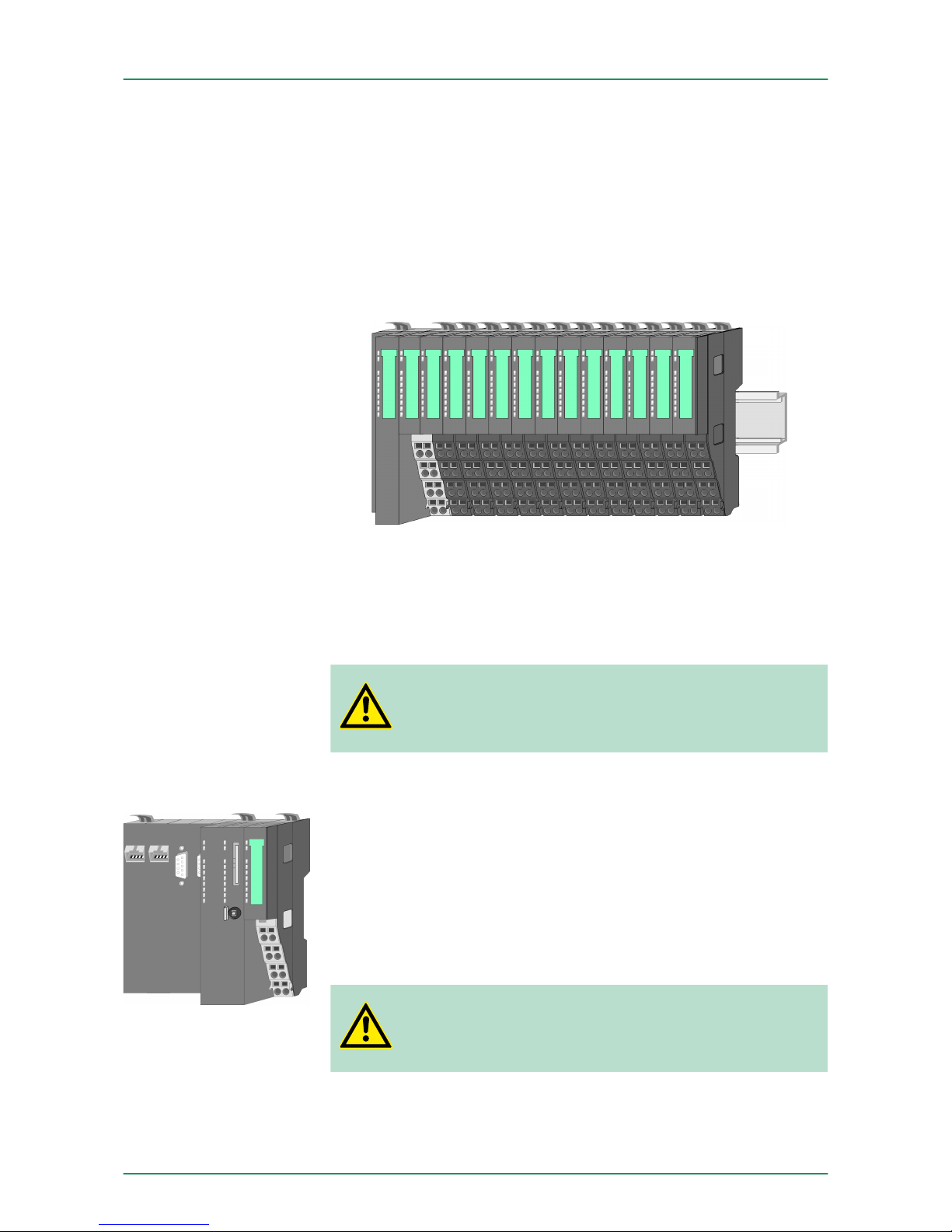
System SLIO is a modular automation system for assembly on a
35mm mounting rail. By means of the peripheral modules with 2, 4 or
8 channels this system may properly be adapted matching to your
automation tasks. The wiring complexity is low, because the supply of
the DC 24V power section is integrated to the backplane bus and
defective modules may be replaced with standing wiring. By deployment of the power modules in contrasting colours within the system,
further isolated areas may be defined for the DC 24V power section
supply, respectively the electronic power supply may be extended
with 2A.
n CPU (head module)
n Bus coupler (head module)
n Periphery modules
n Power modules
n Accessories
CAUTION!
Only modules of VIPA may be combined. A mixed operation with third-party modules is not allowed!
With a CPU, CPU electronic and power module are integrated to one
casing. As head module via the integrated power module for power
supply the CPU electronic is supplied as well as the electronic of the
connected periphery modules. The DC 24 power section supply for
the linked periphery modules is established via a further connection at
the power module. By installing of up to 64 periphery modules at the
CPU, these are electrically connected, this means these are assigned
to the backplane bus, the electronic modules are power supplied and
each periphery module is connected to the DC 24V power section
supply.
CAUTION!
CPU part and power module of a CPU may not be separated! Here you may only exchange the electronic module!
Overview
Components
CPU
VIPA System SLIO Basics and Assembly
System conception
HB300 | FM | 050-1BA00 | GB | 14-36 9
Page 10
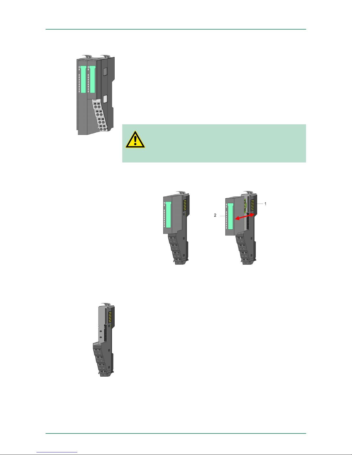
With a bus coupler bus interface and power module are integrated to
one casing. With the bus interface you get access to a subordinated
bus system. As head module via the integrated power module for
power supply the bus interface is supplied as well as the electronic of
the connected periphery modules. The DC 24 power section supply
for the linked periphery modules is established via a further connection at the power module. By installing of up to 64 periphery modules
at the bus coupler, these are electrically connected, this means these
are assigned to the backplane bus, the electronic modules are power
supplied and each periphery module is connected to the DC 24V
power section supply.
CAUTION!
Bus interface and power module of the bus coupler may
not be separated! Here you may only exchange the electronic module!
Each periphery module consists of a terminal and an electronic
module.
1 Terminal module
2 Electronic module
The terminal module serves to carry the electronic module, contains
the backplane bus with power supply for the electronic, the DC 24V
power section supply and the staircase-shaped terminal for wiring.
Additionally the terminal module has a locking system for fixing at a
mounting rail. By means of this locking system your SLIO system may
be assembled outside of your switchgear cabinet to be later mounted
there as whole system.
Bus coupler
Periphery modules
Terminal module
VIPA System SLIOBasics and Assembly
System conception
HB300 | FM | 050-1BA00 | GB | 14-36 10
Page 11
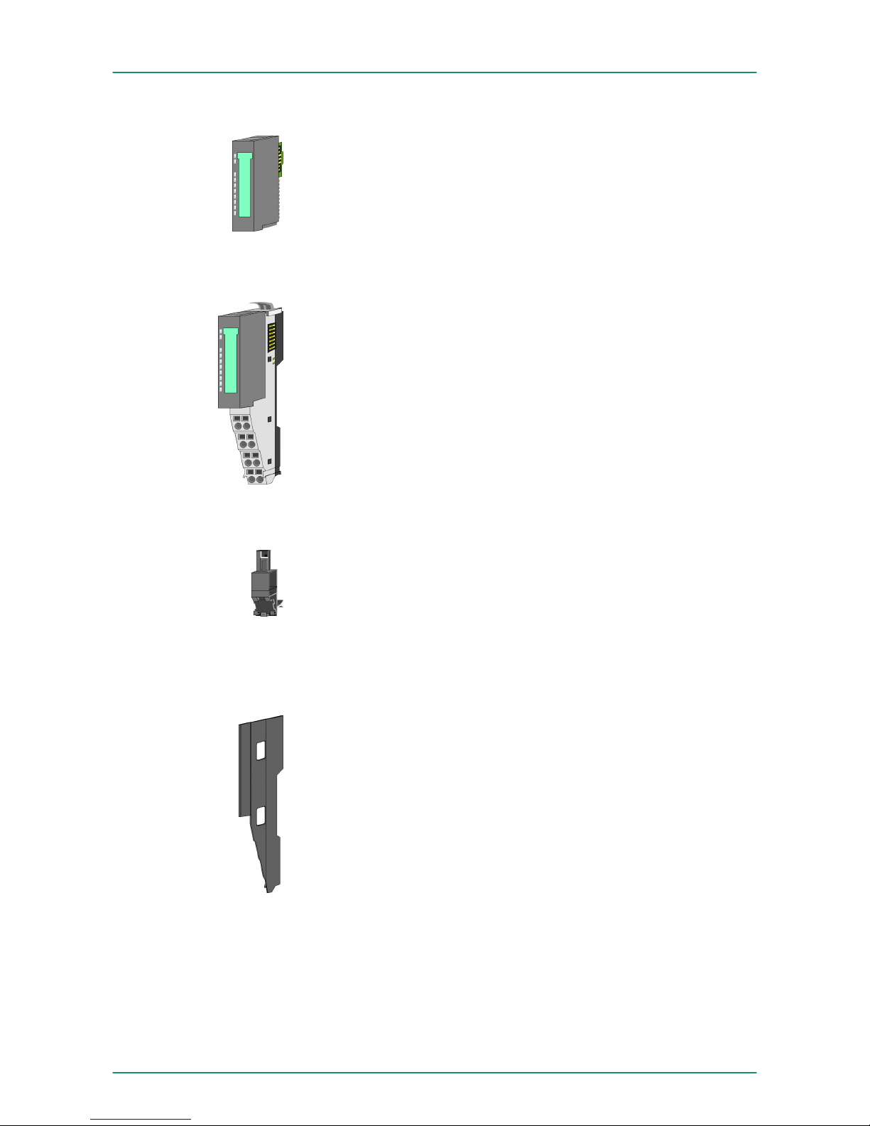
The functionality of a SLIO periphery module is defined by the electronic module, which is mounted to the terminal module by a safe
sliding mechanism. With an error the defective module may be
exchanged for a functional module with standing installation.
At the front side there are LEDs for status indication. For simple
wiring each module shows a corresponding connection diagram at
the front and at the side.
In the System SLIO the power supply is established by power modules. These are either integrated to the bus coupler or may be
installed between the periphery modules. Depending on the power
module isolated areas of the DC 24V power section supply may be
defined respectively the electronic power supply may be extended
with 2A. For better recognition the colour of the power modules are
contrasting to the periphery modules.
The shield bus carrier (order no. 000-0AB00) serves to carry the
shield bus (10mm x 3mm) to connect cable shields. Shield bus carriers, shield bus and shield fixings are not in the scope of delivery.
They are only available as accessories.
The shield bus carrier is mounted underneath the terminal of the terminal module. With a flat mounting rail for adaption to a flat mounting
rail you may remove the spacer of the shield bus carrier.
With each bus coupler, to protect the backplane bus connectors,
there is a mounted bus cover in the scope of delivery. You have to
remove the bus cover of the bus coupler before mounting a SLIO
module. For the protection of the backplane bus connector you
always have to mount the bus cover at the last module of your system
again.
The bus cover has the order no. 000-0AA00.
Electronic module
Power module
Accessories
Shield bus carrier
Bus cover
VIPA System SLIO Basics and Assembly
System conception
HB300 | FM | 050-1BA00 | GB | 14-36 11
Page 12
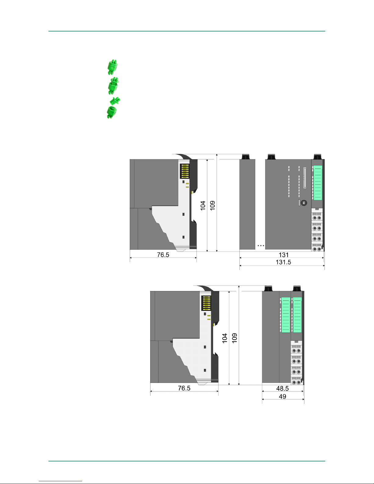
There is the possibility to fix the assignment of electronic and terminal
module. Here coding pins (order number 000-0AC00) from VIPA can
be used.
The coding pin consists of a coding jack and a coding plug. By combining electronic and terminal module with coding pin, the coding jack
remains in the electronic module and the coding plug in the terminal
module.
This ensures that after replacing the electronics module just another
electronic module can be plugged with the same encoding.
2.3 Dimensions
Coding pins
Dimensions CPU
Dimensions bus coupler
VIPA System SLIOBasics and Assembly
Dimensions
HB300 | FM | 050-1BA00 | GB | 14-36 12
Page 13
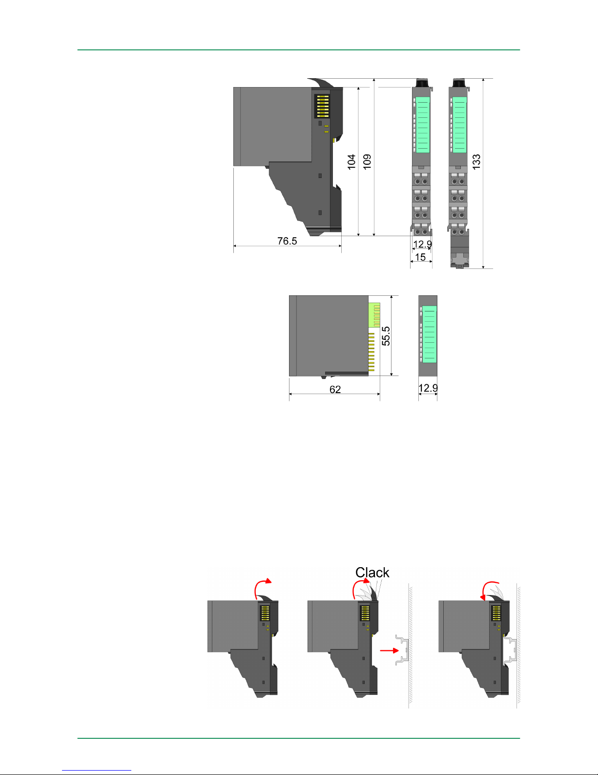
Dimensions in mm
2.4 Installation
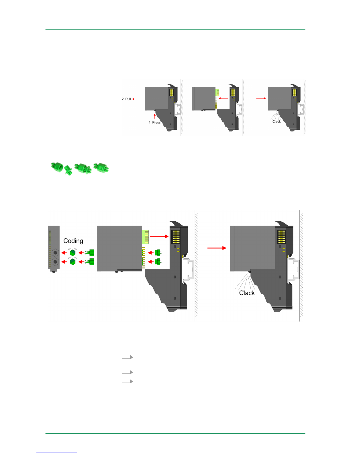
There is a locking lever at the top side of the terminal module. For
mounting and demounting this locking lever is to be turned upwards
until this engages audible. Now the module may be pulled forward.
For mounting plug the module to the module installed before and
push the module to the mounting rail guided by the strips at the upper
and lower side of the module. The module is fixed to the mounting rail
by pushing downward the locking lever. The modules may either separately be mounted to the mounting rail or as block. Here is to be considered that each locking lever is opened.
Dimensions periphery
module
Dimensions electronic
module
Functional principle
VIPA System SLIO Basics and Assembly
Installation
HB300 | FM | 050-1BA00 | GB | 14-36 13
Page 14
For the exchange of a electronic module, the electronic module may
be pulled forward after pressing the unlocking lever at the lower side
of the module. For installation plug the electronic module guided by
the strips at the lower side until this engages audible to the terminal
module.
There is the possibility to fix the assignment of electronic and terminal
module. Here coding pins (order number 000-0AC00) from VIPA can
be used. The coding pin consists of a coding jack and a coding plug.
By combining electronic and terminal module with coding pin, the
coding jack remains in the electronic module and the coding plug in
the terminal module. This ensures that after replacing the electronics
module just another electronic module can be plugged with the same
encoding.
Each electronic module has on its back 2 coding sockets for coding
jacks. Due to the characteristics, with the coding jack 6 different positions can be plugged, each. Thus there are 36 possible combinations
for coding with the use of both coding sockets.
1. Plug, according to your coding, 2 coding jacks in the coding
sockets of your electronic module until they lock.
2. Now plug the according coding plugs into the coding jacks.
3. To fix the coding put both the electronic and terminal module
together until they lock.
Coding
VIPA System SLIOBasics and Assembly
Installation
HB300 | FM | 050-1BA00 | GB | 14-36 14
Page 15
CAUTION!
Please consider that when replacing an already coded
electronic module, this is always be replaced by an electronic module with the same coding.
Even with an existing coding on the terminal module, you
can plug an electronic module without coding. The user is
responsible for the correct usage of the coding pins. VIPA
assumes no liability for incorrectly attached electronic
modules or for damages which arise due to incorrect
coding!
The modules were directly be mounted to the mounting rail and so
connected to the backplane bus and the power supply for the electronic and power section. Up to 64 modules may be mounted. Please
consider here that the sum current of the electronic power supply
does not exceed the maximum value of 3A. By means of the power
module 007-1AB10 the current of the electronic power supply may be
expanded with 2A. Ä Chapter 2.6 ‘Wiring’ on page 22
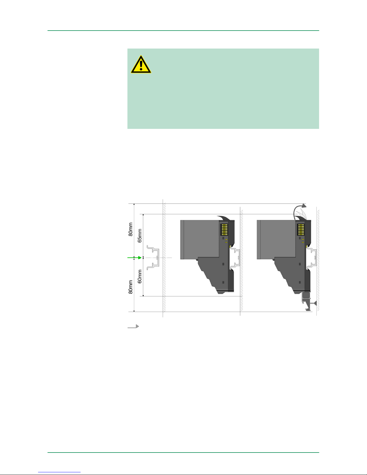
Mounting rail
Mount the mounting rail! Please consider that a clearance from
the middle of the mounting rail of at least 80mm above and
60mm below, respectively 80mm by deployment of shield bus
carriers, exist.
Mounting Proceeding
VIPA System SLIO Basics and Assembly
Installation
HB300 | FM | 050-1BA00 | GB | 14-36 15
Page 16
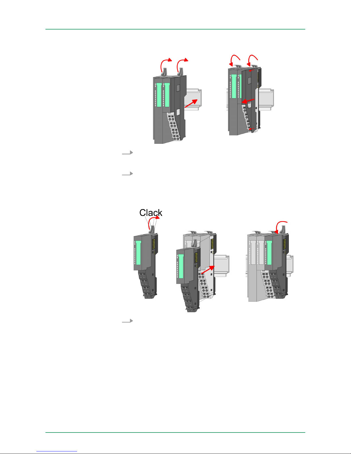
Mounting Head module (e.g. bus coupler)
1. Start at the left side with the head module (e.g. bus coupler). For
this turn both locking lever upwards, put the head module to the
mounting rail and turn both locking lever downward.
2. Before mounting the periphery modules you have to remove the
bus cover at the right side of the Head module by pulling it forward. Keep the cover for later mounting.
Mounting periphery modules
Mount the periphery modules you want.
VIPA System SLIO
Basics and Assembly
Installation
HB300 | FM | 050-1BA00 | GB | 14-36 16
Page 17
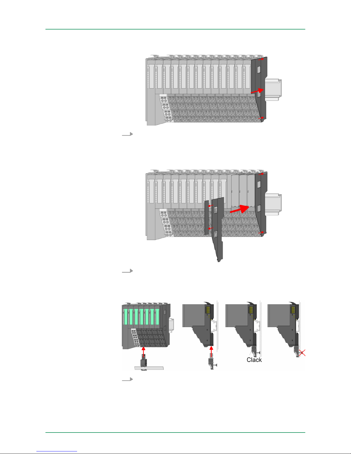
Mounting the bus cover
After mounting the whole system, to protect the backplane bus
connectors at the last module you have to mount the bus cover,
now.
Mounting the bus cover at a clamp module
If the last module is a clamp module, for adaptation the upper
part of the bus cover is to be removed
Mounting shield bus carrier
The shield bus carrier (available as accessory) serves to carry
the shield bus to connect cable shields. The shield bus carrier is
mounted underneath the terminal of the terminal module. With a
flat mounting rail for adaption to a flat mounting rail you may
remove the spacer of the shield bus carrier.
VIPA System SLIO
Basics and Assembly
Installation
HB300 | FM | 050-1BA00 | GB | 14-36 17
Page 18
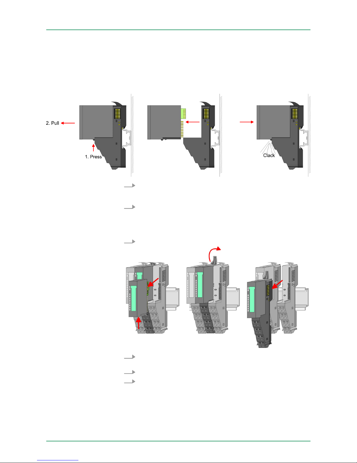
2.5 Demounting and module exchange
With demounting and exchange of a module, head module (e.g. bus
coupler) or a group of modules for mounting reasons you have
always to remove the electronic module of the just mounted right
module. After the mounting it may be plugged again.
Exchange of an electronic module
1. For the exchange of an electronic module, the electronic module
may be pulled forward after pressing the unlocking lever at the
lower side of the module.
2. For installation plug the electronic module guided by the strips at
the lower side until this engages audible to the terminal module.
Exchange of a module
1.
Remove if exists the wiring.
Ä
Chapter 2.6 ‘Wiring’ on page 22.
2. Press the unlocking lever at the lower side of the just mounted
right module and pull it forward.
3. Turn the locking lever of the module to be exchanged upwards.
4. Pull the module forward.
Proceeding
VIPA System SLIOBasics and Assembly
Demounting and module exchange
HB300 | FM | 050-1BA00 | GB | 14-36 18
Page 19
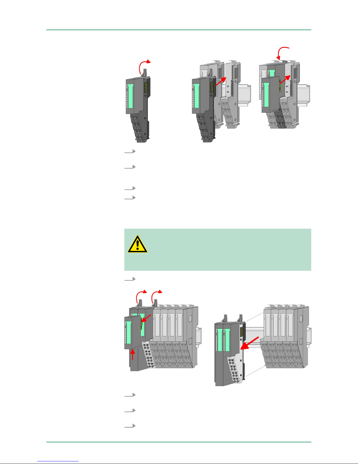
5. For mounting turn the locking lever of the module to be mounted
upwards.
6. To mount the module put it to the gap between the both modules and push it, guided by the stripes at both sides, to the
mounting rail.
7. Turn the locking lever downward again.
8. Plug again the electronic module, which you have removed
before.
Exchange of a head module (e.g. bus coupler)
CAUTION!
Bus interface and power module of a head module may
not be separated!
Here you may only exchange the electronic module!
1.
Remove if exists the wiring of the head module. Ä Chapter 2.6
‘Wiring’ on page 22.
2. Press the unlocking lever at the lower side of the just mounted
right module and pull it forward.
3. Turn all the locking lever of the head module to be exchanged
upwards.
4. Pull the head module forward.
VIPA System SLIO
Basics and Assembly
Demounting and module exchange
HB300 | FM | 050-1BA00 | GB | 14-36 19
Page 20
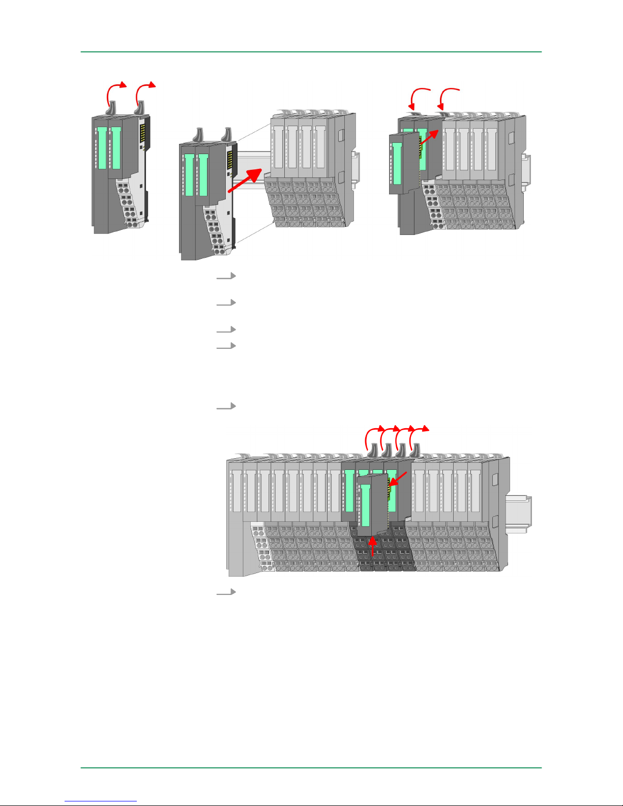
5. For mounting turn all the locking lever of the head module to be
mounted upwards.
6. To mount the head module put it to the left module and push it,
guided by the stripes, to the mounting rail.
7. Turn all the locking lever downward again.
8. Plug again the electronic module, which you have removed
before.
Exchange of a module group
1.
Remove if exists the wiring of the module group. Ä Chapter 2.6
‘Wiring’ on page 22.
2. Press the unlocking lever at the lower side of the just mounted
right module of the module group and pull it forward.
VIPA System SLIO
Basics and Assembly
Demounting and module exchange
HB300 | FM | 050-1BA00 | GB | 14-36 20
Page 21
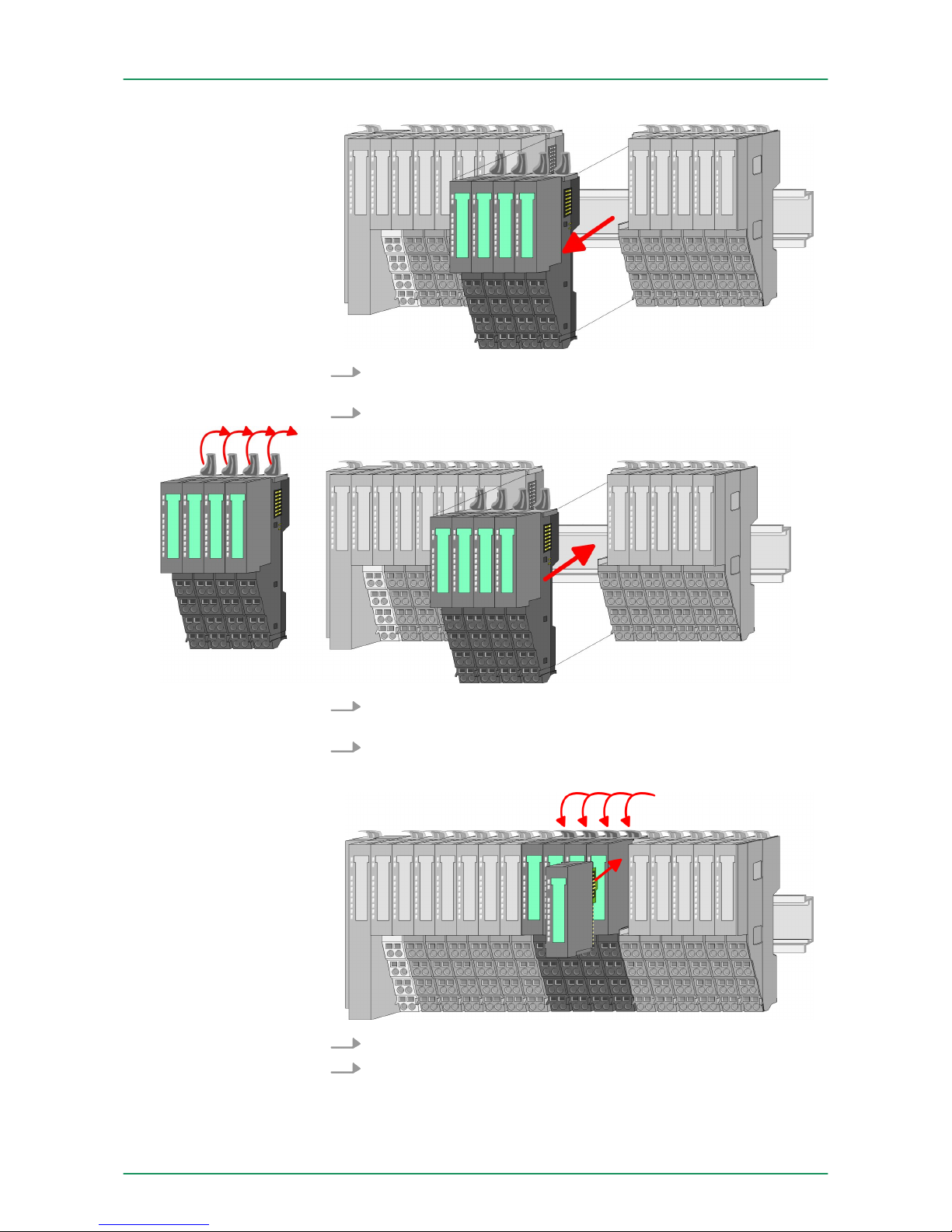
3. Turn all the locking lever of the module group to be exchanged
upwards.
4. Pull the module group forward.
5. For mounting turn all the locking lever of the module group to be
mounted upwards.
6. To mount the module group put it to the gap between the both
modules and push it, guided by the stripes at both sides, to the
mounting rail.
7. Turn all the locking lever downward again.
8. Plug again the electronic module, which you have removed
before.
VIPA System SLIO
Basics and Assembly
Demounting and module exchange
HB300 | FM | 050-1BA00 | GB | 14-36 21
Page 22
2.6 Wiring
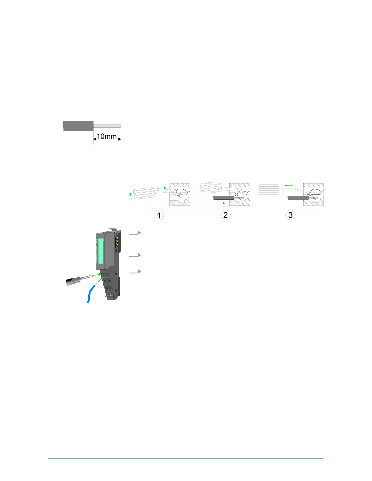
Terminals with spring clamp technology are used for wiring.
The spring clamp technology allows quick and easy connection of
your signal and supply lines.
In contrast to screw terminal connections this type of connection is
vibration proof.
U
max
: 240V AC / 30V DC
I
max
: 10A
Cross section: 0.08 ... 1.5mm2 (AWG 28 ... 16)
Stripping length: 10mm
1. Insert a suited screwdriver at an angel into the square opening
as shown. Press and hold the screwdriver in the opposite direction to open the contact spring.
2. Insert the stripped end of wire into the round opening. You can
use wires with a cross section of 0.08mm2 to 1.5mm2.
3. By removing the screwdriver, the wire is securely fixed via the
spring contact to the terminal.
Connectors
Data
Wiring procedure
VIPA System SLIOBasics and Assembly
Wiring
HB300 | FM | 050-1BA00 | GB | 14-36 22
Page 23
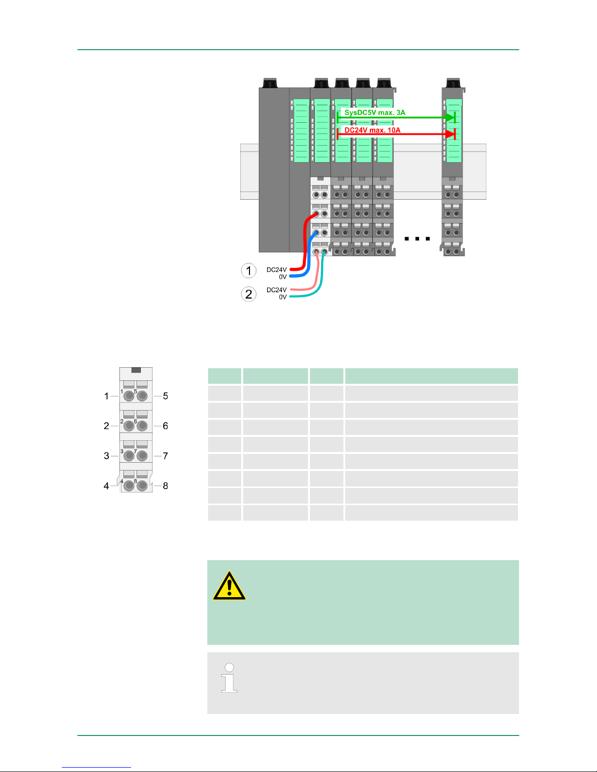
(1) DC 24V for power section supply I/O area (max 10A)
(2) DC 24V for electronic power supply bus coupler and I/O area
For wires with a core cross-section of 0.08mm2 up to 1.5mm2.
Pos. Function Type Description
1 --- --- not connected
2 DC 24V I DC 24V for power section supply
3 0V I GND for power section supply
4 Sys DC 24V I DC 24V for electronic section supply
5 --- --- not connected
6 DC 24V I DC 24V for power section supply
7 0V I GND for power section supply
8 Sys 0V I GND for electronic section supply
I Input
CAUTION!
Since the power section supply is not internally protected,
it is to be externally protected with a fuse, which corresponds to the maximum current. This means max. 10A is
to be protected by a 10A fuse (fast) respectively by a line
circuit breaker 10A characteristics Z!
The electronic power section supply is internally protected
against higher voltage by fuse. The fuse is within the
power module. If the fuse releases, its electronic module
must be exchanged!
Standard wiring
PM - Power module
VIPA System SLIO Basics and Assembly
Wiring
HB300 | FM | 050-1BA00 | GB | 14-36 23
Page 24
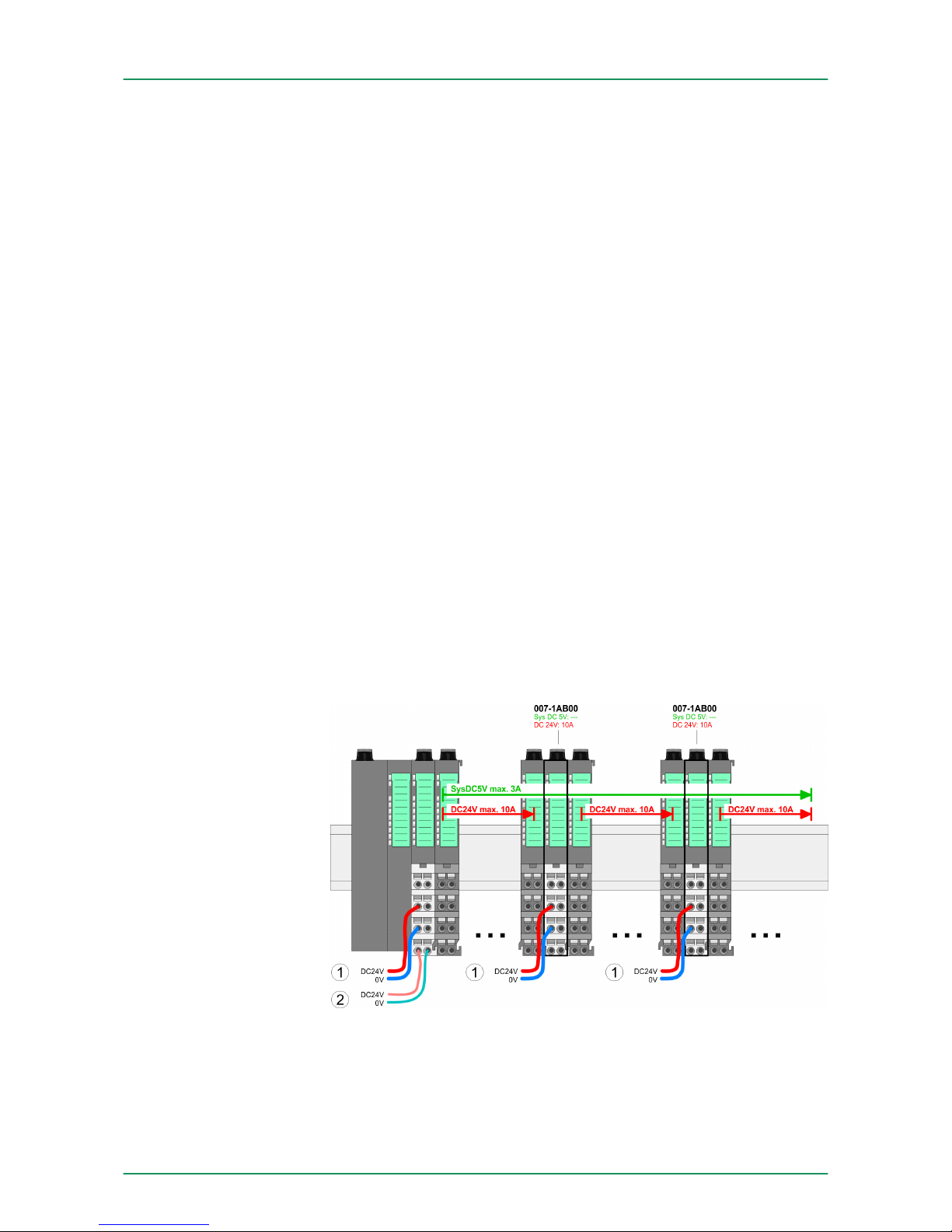
n The power section supply is to be externally protected with a fuse,
which corresponds to the maximum current. This means max. 10A
is to be protected with a 10A fuse (fast) respectively by a line circuit breaker 10A characteristics Z!
n It is recommended to externally protect the electronic power
supply for bus coupler and I/O area with a 2A fuse (fast) respectively by a line circuit breaker 2A characteristics Z.
n The electronic power supply for the I/O area of the power module
007-1AB10 should also be externally protected with a 1A fuse
(fast) respectively by a line circuit breaker 1A characteristics Z.
After PowerON of the System SLIO the LEDs RUN respectively MF
get on so far as the sum current does not exceed 3A.
With a sum current greater than 3A the LEDs may not be activated.
Here the power module with the order number 007-1AB10 is to be
placed between the peripheral modules.
If the 10A for the power section supply is no longer sufficient, you
may use the power module from VIPA with the order number
007-1AB00. So you have also the possibility to define isolated
groups.
The power module with the order number 007-1AB10 is to be used if
the 3A for the electronic power supply at the backplane bus is no
longer sufficient. Additionally you get an isolated group for the DC
24V power section supply with 4A.
By placing the power module 007-1AB10 at the following backplane
bus modules may be placed with a sum current of max. 2A. Afterwards the power module 007-1AB10 is to be placed again. To secure
the power supply, the power modules may be mixed used.
Fusing
State of the electronic
power supply via LEDs
Deployment of the
power modules
Power module
007-1AB00
VIPA System SLIOBasics and Assembly
Wiring
HB300 | FM | 050-1BA00 | GB | 14-36 24
Page 25
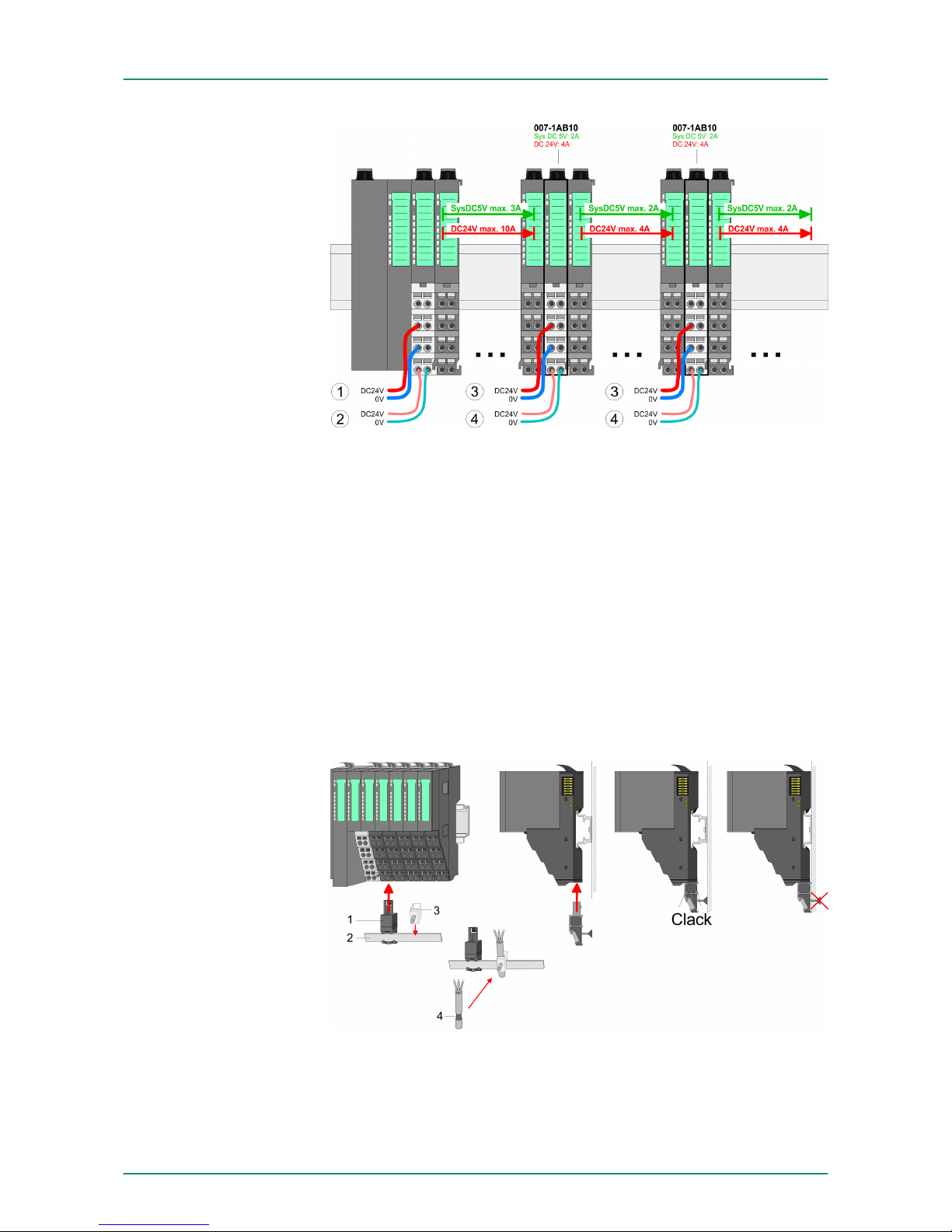
(1) DC 24V for power section supply I/O area (max. 10A)
(2) DC 24V for electronic power supply bus coupler and I/O area
(3) DC 24V for power section supply I/O area (max. 4A)
(4) DC 24V for electronic power supply I/O area
To attach the shield the mounting of shield bus carriers are necessary.
The shield bus carrier (available as accessory) serves to carry the
shield bus to connect cable shields.
The shield bus carrier is mounted underneath the terminal of the terminal module. With a flat mounting rail for adaption to a flat mounting
rail you may remove the spacer of the shield bus carrier.
After mounting the shield bus carrier with the shield bus, the cables
with the accordingly stripped cable screen may be attached and fixed
by the shield clamp.
1 Shield bus carrier
2 Shield bus (10mm x 3mm)
3 Shield clamp
4 Cable shield
Power module
007-1AB10
Shield attachment
VIPA System SLIO Basics and Assembly
Wiring
HB300 | FM | 050-1BA00 | GB | 14-36 25
Page 26
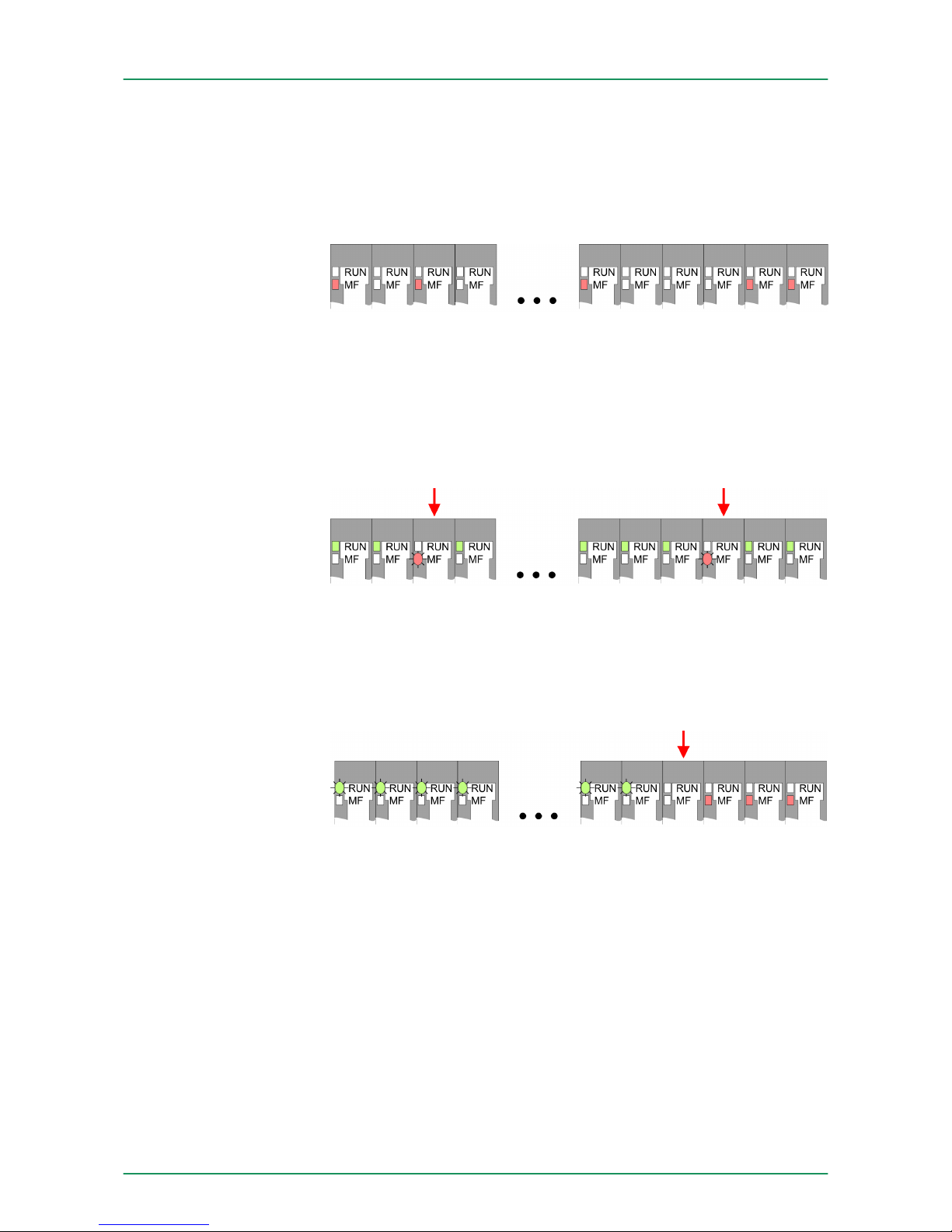
2.7 Trouble shooting - LEDs
Each module has the LEDs RUN and MF on its front side. Errors or
incorrect modules may be located by means of these LEDs.
In the following illustrations flashing LEDs are marked by ☼.
Behaviour: After PowerON the RUN LED of each module is off and
the MF LED of each module is sporadically on.
Reason: The maximum current for the electronic power supply is
exceeded.
Remedy: As soon as the sum current of the electronic power supply
is exceeded, always place the power module 007-1AB10.
Ä
Chapter 2.6 ‘Wiring’ on page 22.
Behaviour: After PowerON the MF LED of one module respectively
more modules flashes. The RUN LED remains off.
Reason: At this position a module is placed, which does not corre-
spond to the configured module.
Remedy: Match configuration and hardware structure.
Behaviour: After PowerON all of the RUN LEDs up to the defective
module are flashing. With all following modules the MF LED is on and
the RUN LED is off.
Reason: The module on the right of the flashing modules is defective.
Remedy: Replace the defective module.
2.8 Installation guidelines
The installation guidelines contain information about the interference
free deployment of a PLC system. There is the description of the
ways, interference may occur in your PLC, how you can make sure
the electromagnetic compatibility (EMC), and how you manage the
isolation.
General
Sum current of the electronic power supply
exceeded
Error in configuration
Module failure
General
VIPA System SLIOBasics and Assembly
Installation guidelines
HB300 | FM | 050-1BA00 | GB | 14-36 26
Page 27

Electromagnetic compatibility (EMC) means the ability of an electrical
device, to function error free in an electromagnetic environment
without being interfered respectively without interfering the environment.
The components of VIPA are developed for the deployment in industrial environments and meets high demands on the EMC. Nevertheless you should project an EMC planning before installing the components and take conceivable interference causes into account.
Electromagnetic interferences may interfere your control via different
ways:
n Electromagnetic fields (RF coupling)
n Magnetic fields with power frequency
n Bus system
n Power supply
n Protected earth conductor
Depending on the spreading medium (lead bound or lead free) and
the distance to the interference cause, interferences to your control
occur by means of different coupling mechanisms.
There are:
n galvanic coupling
n capacitive coupling
n inductive coupling
n radiant coupling
In the most times it is enough to take care of some elementary rules
to guarantee the EMC. Please regard the following basic rules when
installing your PLC.
n Take care of a correct area-wide grounding of the inactive metal
parts when installing your components.
– Install a central connection between the ground and the pro-
tected earth conductor system.
– Connect all inactive metal extensive and impedance-low.
– Please try not to use aluminium parts. Aluminium is easily oxi-
dizing and is therefore less suitable for grounding.
n When cabling, take care of the correct line routing.
– Organize your cabling in line groups (high voltage, current
supply, signal and data lines).
– Always lay your high voltage lines and signal respectively data
lines in separate channels or bundles.
– Route the signal and data lines as near as possible beside
ground areas (e.g. suspension bars, metal rails, tin cabinet).
n Proof the correct fixing of the lead isolation.
– Data lines must be laid isolated.
– Analog lines must be laid isolated. When transmitting signals
with small amplitudes the one sided laying of the isolation may
be favourable.
– Lay the line isolation extensively on an isolation/protected
earth conductor rail directly after the cabinet entry and fix the
isolation with cable clamps.
– Make sure that the isolation/protected earth conductor rail is
connected impedance-low with the cabinet.
– Use metallic or metallised plug cases for isolated data lines.
What does EMC mean?
Possible interference
causes
Basic rules for EMC
VIPA System SLIO Basics and Assembly
Installation guidelines
HB300 | FM | 050-1BA00 | GB | 14-36 27
Page 28

n In special use cases you should appoint special EMC actions.
– Consider to wire all inductivities with erase links.
– Please consider luminescent lamps can influence signal lines.
n Create a homogeneous reference potential and ground all elec-
trical operating supplies when possible.
– Please take care for the targeted employment of the grounding
actions. The grounding of the PLC serves for protection and
functionality activity.
– Connect installation parts and cabinets with your PLC in star
topology with the isolation/protected earth conductor system.
So you avoid ground loops.
– If there are potential differences between installation parts and
cabinets, lay sufficiently dimensioned potential compensation
lines.
Electrical, magnetically and electromagnetic interference fields are
weakened by means of an isolation, one talks of absorption. Via the
isolation rail, that is connected conductive with the rack, interference
currents are shunt via cable isolation to the ground. Here you have to
make sure, that the connection to the protected earth conductor is
impedance-low, because otherwise the interference currents may
appear as interference cause.
When isolating cables you have to regard the following:
n If possible, use only cables with isolation tangle.
n The hiding power of the isolation should be higher than 80%.
n Normally you should always lay the isolation of cables on both
sides. Only by means of the both-sided connection of the isolation
you achieve high quality interference suppression in the higher
frequency area. Only as exception you may also lay the isolation
one-sided. Then you only achieve the absorption of the lower frequencies. A one-sided isolation connection may be convenient, if:
– the conduction of a potential compensating line is not possible.
– analog signals (some mV respectively µA) are transferred.
– foil isolations (static isolations) are used.
n With data lines always use metallic or metallised plugs for serial
couplings. Fix the isolation of the data line at the plug rack. Do not
lay the isolation on the PIN 1 of the plug bar!
n At stationary operation it is convenient to strip the insulated cable
interruption free and lay it on the isolation/protected earth conductor line.
n To fix the isolation tangles use cable clamps out of metal. The
clamps must clasp the isolation extensively and have well contact.
n Lay the isolation on an isolation rail directly after the entry of the
cable in the cabinet. Lead the isolation further on to your PLC and
don't lay it on there again!
CAUTION!
Please regard at installation!
At potential differences between the grounding points,
there may be a compensation current via the isolation connected at both sides.
Remedy: Potential compensation line
Isolation of conductors
VIPA System SLIOBasics and Assembly
Installation guidelines
HB300 | FM | 050-1BA00 | GB | 14-36 28
Page 29
2.9 General data
Conformity and approval
Conformity
CE 2006/95/EG Low-voltage directive
2004/108/EG EMC directive
Approval
UL UL 508 Approval for USA and Canada
others
RoHS 2011/65/EU Product is lead-free; Restriction of the use of
certain hazardous substances in electrical and
electronic equipment
Protection of persons and device protection
Type of protection - IP20
Electrical isolation
to the field bus - electrically isolated
to the process level - electrically isolated
Insulation resistance -
Insulation voltage to reference earth
Inputs / outputs - AC / DC 50V, test voltage AC 500V
Protective measures - against short circuit
Environmental conditions to EN 61131-2
Climatic
Storage / transport EN 60068-2-14 -25…+70°C
Operation
Horizontal installation EN 61131-2 0…+60°C
Vertical installation EN 61131-2 0…+60°C
Air humidity EN 60068-2-30 RH1 (without condensation, rel. humidity 10…
95%)
Pollution EN 61131-2 Degree of pollution 2
Mechanical
Oscillation EN 60068-2-6 1g, 9Hz ... 150Hz
Shock EN 60068-2-27 15g, 11ms
VIPA System SLIO Basics and Assembly
General data
HB300 | FM | 050-1BA00 | GB | 14-36 29
Page 30

Mounting conditions
Mounting place - In the control cabinet
Mounting position - Horizontal and vertical
EMC Standard Comment
Emitted interference
EN 61000-6-4 Class A (Industrial area)
Noise immunity
zone B
EN 61000-6-2 Industrial area
EN 61000-4-2
ESD
8kV at air discharge (degree of severity 3),
4kV at contact discharge (degree of severity
2)
EN 61000-4-3 HF field immunity (casing)
80MHz … 1000MHz, 10V/m, 80% AM (1kHz)
1.4GHz ... 2.0GHz, 3V/m, 80% AM (1kHz)
2GHz ... 2.7GHz, 1V/m, 80% AM (1kHz)
EN 61000-4-6 HF conducted
150kHz … 80MHz, 10V, 80% AM (1kHz)
EN 61000-4-4 Burst, degree of severity 3
EN 61000-4-5 Surge, installation class 3 *
*) Due to the high-energetic single pulses with Surge an appropriate external protective circuit with lightning protection elements like conductors
for lightning and overvoltage is necessary.
VIPA System SLIOBasics and Assembly
General data
HB300 | FM | 050-1BA00 | GB | 14-36 30
Page 31
3 Hardware description
3.1 Properties
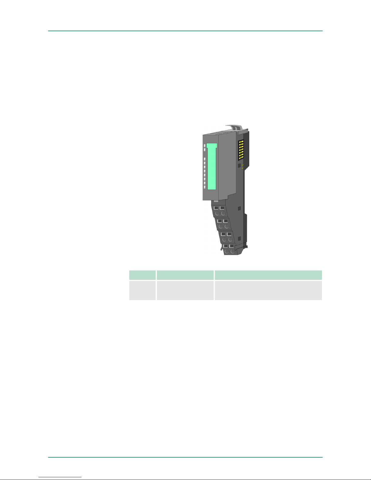
n 1 counter 32bit (AB) invertible, DC 24V
n Counting frequency max 400kHz (AB 1/2/4-fold evaluation or
pulse and direction)
n Latch value, comparison value, set value, input filter (configurable)
n HW gate, reset, digital output for comparison
n Interrupt and diagnostics function with µs time stamp
n µs time stamp for counter value (e.g. for speed calculation)
Type Order number Description
FM 050 050-1BA00 Counter module advanced 1x32bit
DC 24V, DO 1xDC 24V 0.5A
Features
Order data
VIPA System SLIO Hardware description
Properties
HB300 | FM | 050-1BA00 | GB | 14-36 31
Page 32
3.2 Structure
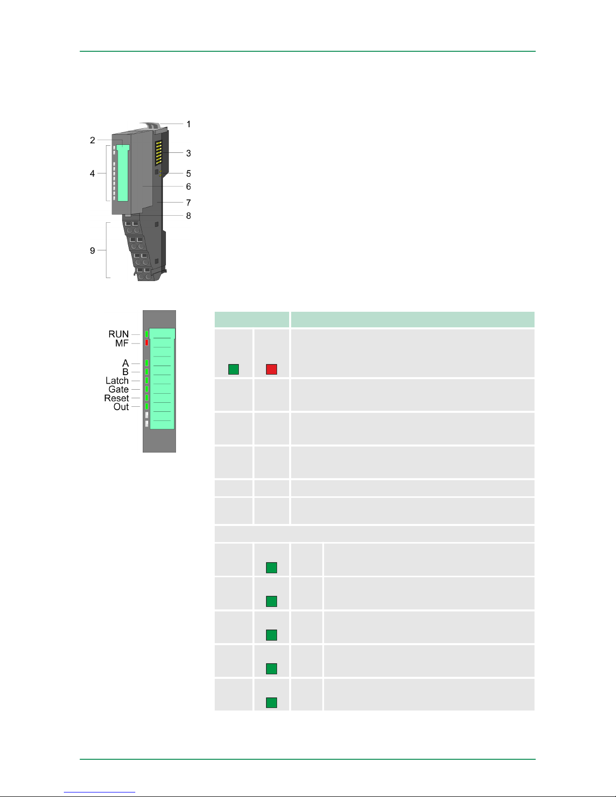
1 Locking lever terminal module
2 Labeling strip
3 Backplane bus
4 LED status indication
5 DC 24V power section supply
6 Electronic module
7 Terminal module
8 Locking lever electronic module
9 Terminal
LED Description
RUN
greenMFred
● ○
Bus communication is OK
Module status is OK
● ●
Bus communication is OK
Module status reports an error
○ ●
Bus communication is not possible
Module status reports an error
○ ○ Error at bus power supply
B B
Error in configuration Ä Chapter 2.7 ‘Trouble
shooting - LEDs’ on page 26
A
green
●
Digital input 1
A/pulse is set
B
green
●
Digital input 5
B/direction is set
Latch
green
●
Digital input 4
Latch is set
Gate
green
●
Digital input 8
hardware gate is set
Reset
green
●
Digital input 7
Reset is set
050-1BA00
Status indication
VIPA System SLIOHardware description
Structure
HB300 | FM | 050-1BA00 | GB | 14-36 32
Page 33
LED Description
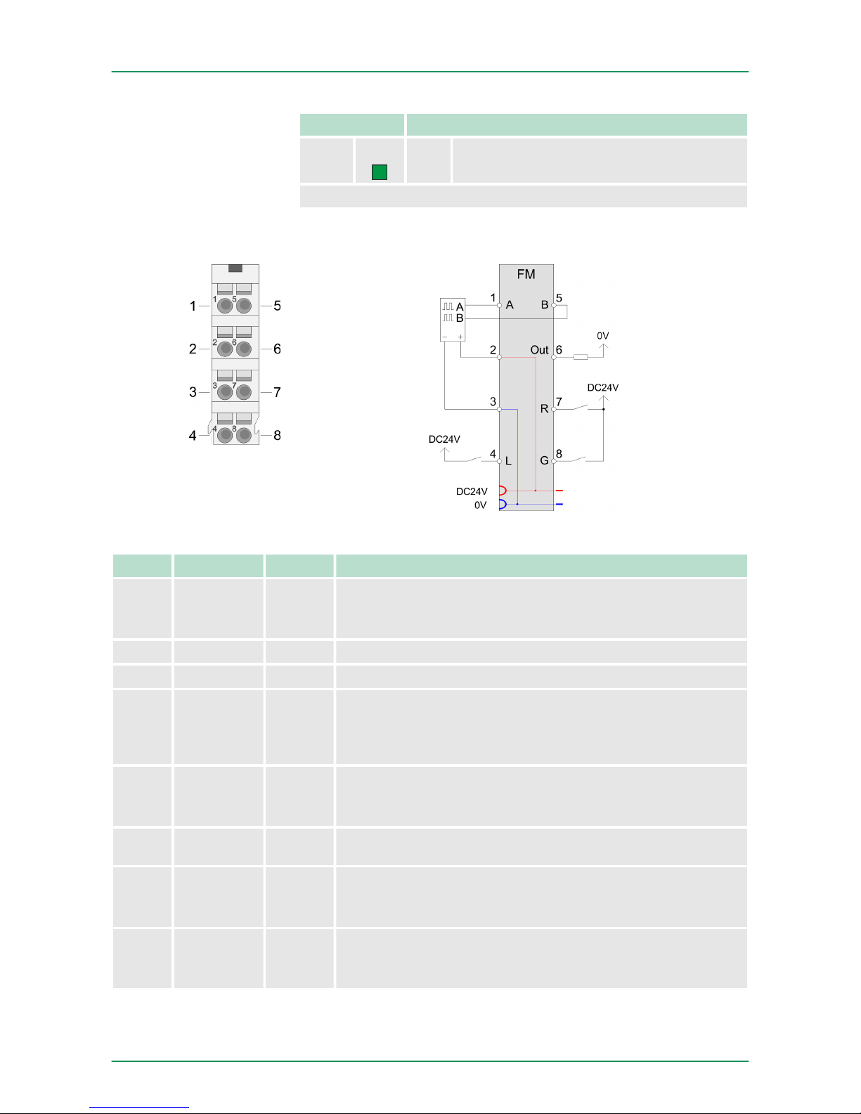
OUT
green
● Digital output 6 is set
on: ● | off: ○ | blinks with 2Hz: B
For wires with a cross section of 0.08mm2 up to 1.5mm2.
Pos. Function Type Description
1 A I A / pulse
Pulse input for counter signal respectively track A of an
encoder for 1-, 2- or 4-fold evaluation.
2 DC 24V O DC 24V for encoder
3 0V O GND
4 L I Latch
Input to store the current counter value as latch value in the
input area. The storage happens with an edge 0-1 respectively
a level-triggered signal.
5 B I B / direction
direction signal respectively track B of an encoder (invertible
via parameterization)
6 Out O Digital output controlled by means of the comparison func-
tions.
7 R I Reset
Input to reset the counter, if the reset functionality was enabled within the parameterization.
8 G I Hardware gate
Input to control the HW gate. The HW gate is controlled by a
high level.
I: Input, O: Output
Pin assignment
VIPA System SLIO Hardware description
Structure
HB300 | FM | 050-1BA00 | GB | 14-36 33
Page 34
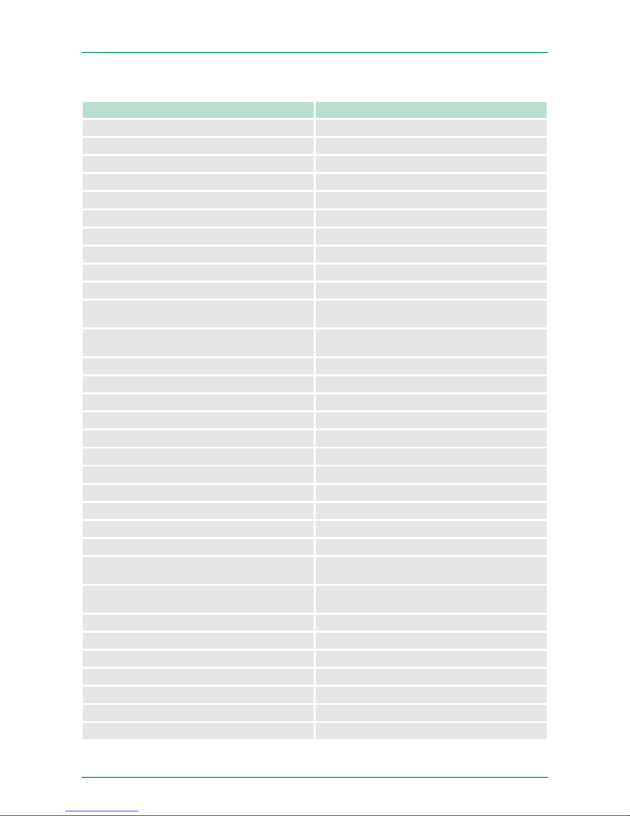
3.3 Technical data
Order no. 050-1BA00
Type FM 050
Module ID 08C1 3800
Current consumption/power loss
Current consumption from backplane bus 75 mA
Power loss 1 W
Technical data digital inputs
Number of inputs 5
Cable length, shielded 100 m
Cable length, unshielded -
Rated load voltage DC 20.4...28.8 V
Reverse polarity protection of rated load
voltage
-
Current consumption from load voltage L+
(without load)
20 mA
Rated value DC 20.4...28.8 V
Input voltage for signal "0" DC 0...5 V
Input voltage for signal "1" DC 15...28.8 V
Input voltage hysteresis -
Frequency range -
Input resistance -
Input current for signal "1" 3 mA
Connection of Two-Wire-BEROs possible
ü
Max. permissible BERO quiescent current 0.5 mA
Input delay of "0" to "1" 0.8 µs
Input delay of "1" to "0" 0.8 µs
Number of simultaneously utilizable inputs horizontal configuration
5
Number of simultaneously utilizable inputs vertical configuration
5
Input characteristic curve IEC 61131-2, type 1
Initial data size 12 Byte
Technical data digital outputs
Number of outputs 1
Cable length, shielded 100 m
Cable length, unshielded 100 m
Rated load voltage DC 20.4...28.8 V
VIPA System SLIOHardware description
Technical data
HB300 | FM | 050-1BA00 | GB | 14-36 34
Page 35
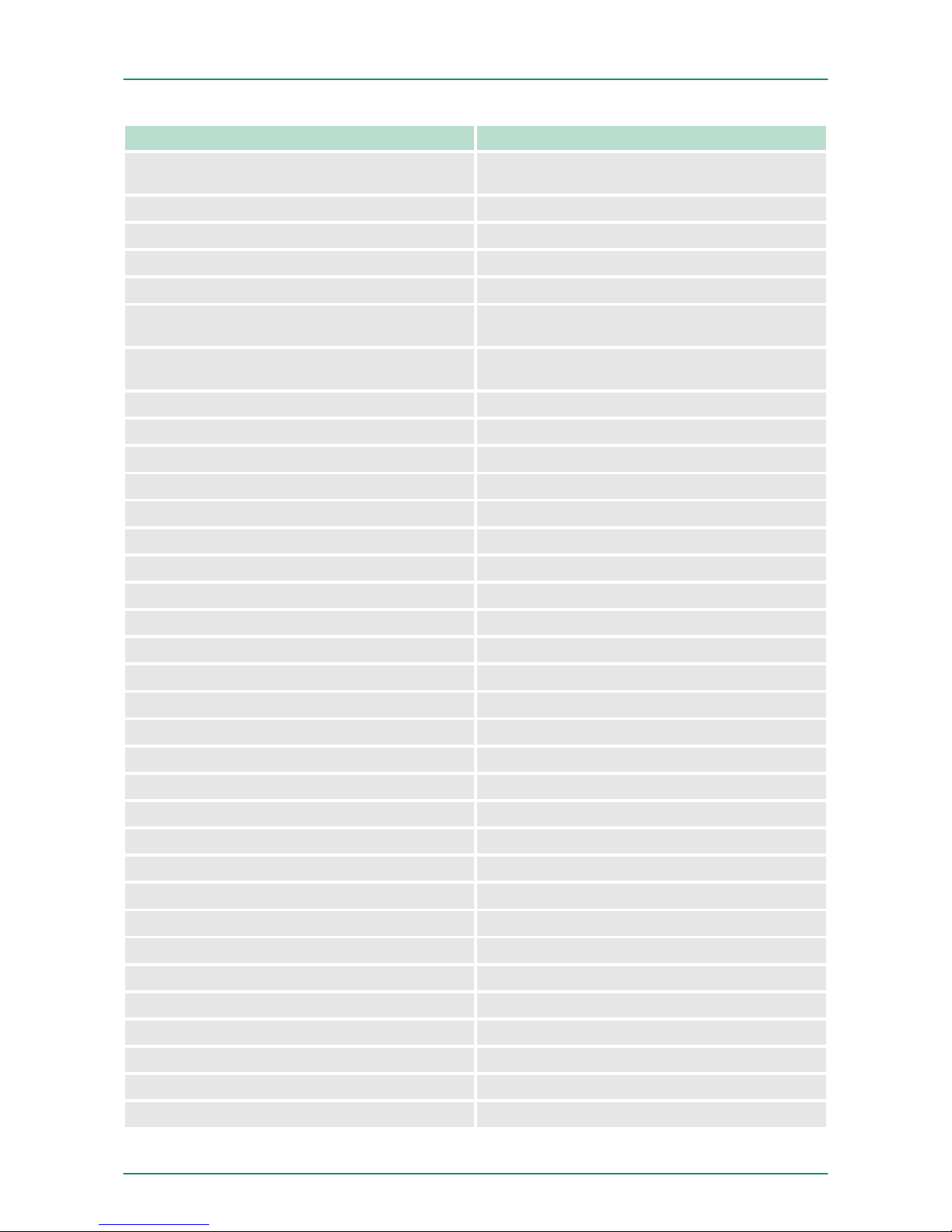
Order no. 050-1BA00
Current consumption from load voltage L+
(without load)
-
Output delay of "0" to "1" 30 µs
Output delay of "1" to "0" 30 µs
Minimum load current -
Lamp load 10 W
Parallel switching of outputs for redundant control of a load
not possible
Parallel switching of outputs for increased
power
not possible
Actuation of digital input
ü
Switching frequency with resistive load max. 10 kHz
Switching frequency with inductive load max. 0.5 Hz
Switching frequency on lamp load max. 10 kHz
Internal limitation of inductive shut-off voltage L+ (-52 V)
Short-circuit protection of output yes, electronic
Trigger level 1 A
Number of operating cycle of relay outputs -
Switching capacity of contacts -
Output data size 10 Byte
Technical data counters
Number of counters 1
Counter width 32 Bit
Maximum input frequency 100 kHz
Maximum count frequency 400 kHz
Mode incremental encoder
ü
Mode pulse / direction
ü
Mode pulse -
Mode frequency counter -
Mode period measurement -
Gate input available
ü
Latch input available
ü
Reset input available
ü
Counter output available
ü
Status information, alarms, diagnostics
Status display yes
Interrupts yes, parameterizable
VIPA System SLIO Hardware description
Technical data
HB300 | FM | 050-1BA00 | GB | 14-36 35
Page 36
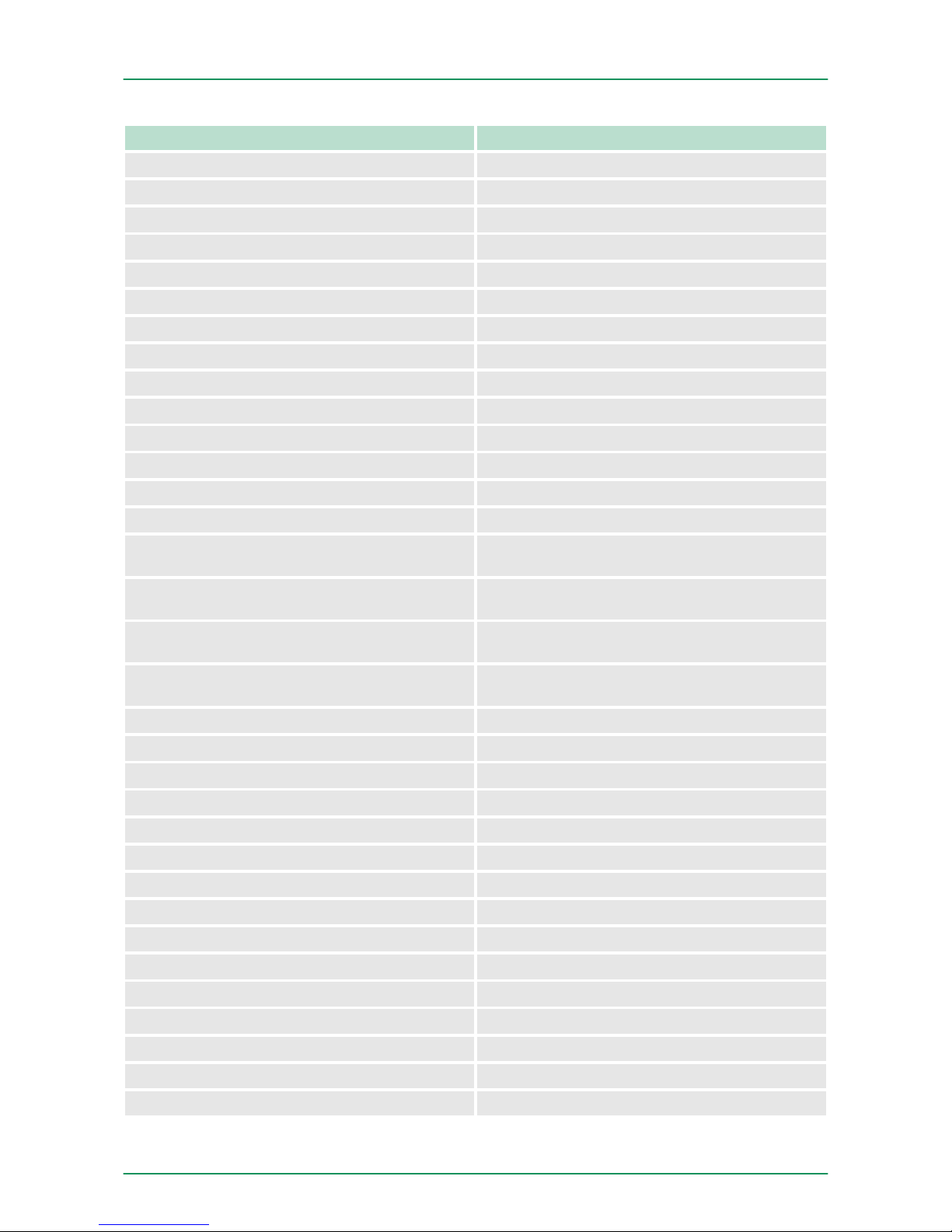
Order no. 050-1BA00
Process alarm yes, parameterizable
Diagnostic interrupt yes, parameterizable
Diagnostic functions yes, parameterizable
Diagnostics information read-out possible
Module state green LED
Module error display red LED
Channel error display none
Isolation
Between channels -
Between channels of groups to -
Between channels and backplane bus
ü
Between channels and power supply -
Max. potential difference between circuits -
Max. potential difference between inputs (Ucm) -
Max. potential difference between Mana and
Mintern (Uiso)
-
Max. potential difference between inputs and
Mana (Ucm)
-
Max. potential difference between inputs and
Mintern (Uiso)
-
Max. potential difference between Mintern and
outputs
-
Insulation tested with DC 500 V
Datasizes
Input bytes 12
Output bytes 10
Parameter bytes 25
Diagnostic bytes 20
Housing
Material PPE / PPE GF10
Mounting Profile rail 35 mm
Mechanical data
Dimensions (WxHxD) 12.9 mm x 109 mm x 76.5 mm
Weight 60 g
Environmental conditions
Operating temperature 0 °C to 60 °C
Storage temperature -25 °C to 70 °C
VIPA System SLIOHardware description
Technical data
HB300 | FM | 050-1BA00 | GB | 14-36 36
Page 37

Order no. 050-1BA00
Certifications
UL508 certification yes
VIPA System SLIO Hardware description
Technical data
HB300 | FM | 050-1BA00 | GB | 14-36 37
Page 38
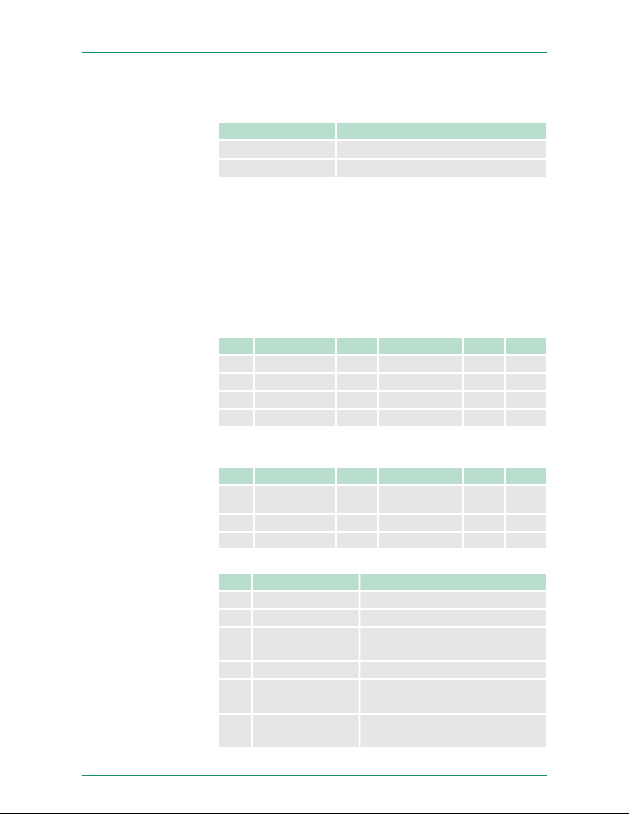
4 Deployment
4.1 Fast introduction
Limits Valid range of values
Lower counter limit
-2 147 483 648 (-231)
Upper counter limit
+2 147 483 647 (231-1)
The maximum counter frequency is 400kHz.
At CPU, PROFIBUS and PROFINET the input respectively output
area is embedded to the corresponding address area.
IX - Index for access via CANopen
SX - Subindex for access via EtherCAT
Input area
Addr. Name Bytes Function IX SX
+0 CV_I 4 Counter value 5400h 01h
+4 CL_I 4 Latch value 5401h 02h
+8 CSTS_I 2 Counter status 5402h 03h
+10 C_US 2 µs ticker 5403h 04h
Output area
Addr. Name Bytes Function IX SX
+0 CC_I 4 Comparison
value
5600h 01h
+4 CS_I 4 Set value 5601h 02h
+8 CCTRL_I 2 Control word 5602h 03h
Bit Name Function
0 STS_SYNC Reset was active
1 STS_CTRL_DO Is set when digital output is enabled
2 STS_SW-GATE Status software gate
(set when SW gate is active)
3 STS_RST Status reset input
4 STS_STRT Status hardware gate
(set when HW gate is active)
5 STS_GATE Status internal gate
(set when internal gate active)
Counter range
Address areas
CSTS_I Counter status
VIPA System SLIODeployment
Fast introduction
HB300 | FM | 050-1BA00 | GB | 14-36 38
Page 39
Bit Name Function
6 STS_DO Status digital counter output (DO)
7 STS_C_DN Status set at counter direction back-
ward
8 STS_C_UP Status set at counter direction forward
9 STS_CMP* Status comparison is set when the
comparison condition is met.
If comparison is parameterized never,
the bit is never set.
10 STS_END* Status is set
when end value was reached
11 STS_OFLW* Status is set at overflow
12 STS_UFLW* Status is set at underflow
13 STS_ZP* Status is set at zero run
14 STS_LTCH Status of the latch input
15 - reserved
*) The bits remain set until reset with RES_SET (bit 6 control word).
Bit Name Function
0 CTRL_SYNC_SET activates the reset mode
1 CTRL_DO_SET enables the digital output
2 SW_GATE_SET sets the software gate
3 ...4- reserved
5 COUNTERVAL_SET sets counter temporarily
to the value of set value
6 RES_SET resets the bits
STS_CMP, STS_END, STS_OFLW,
STS_UFLW
and STS_ZP with edge 0-1
7 - reserved
8 CTRL_SYNC_RESET deactivates the reset mode
9 CTRL_DO_RESET disables the digital output
10 SW_GATE_RESET resets the software gate
11 ...15- reserved
CCTRL_I Control word
VIPA System SLIO Deployment
Fast introduction
HB300 | FM | 050-1BA00 | GB | 14-36 39
Page 40
DS - Data set for access via CPU, PROFIBUS and PROFINET
IX - Index for access via CANopen
SX - Subindex for access via EtherCAT
Name Bytes Function Default DS IX SX
DIAG_EN 1 Diagnostic interrupt* 00h 00h 3100h 01h
CH0A 1 Input frequency track A 02h 01h 3101h 02h
CH1B 1 Input frequency track B 02h 01h 3102h 03h
CH2L 1 Input frequency Latch 02h 01h 3103h 04h
CH3G 1 Input frequency Gate 02h 01h 3104h 05h
CH4R 1 Input frequency Reset 02h 01h 3105h 06h
CH5 1 0 (fix) 00h 01h 3106h 07h
INT_I 1 Interrupt behavior* 80h 80h 3107h 08h
FCT_I 1 Counter function* 40h 80h 3108h 09h
MODE2_I 1 Counter mode 2* 00h 80h 3109h 0Ah
MODE3_I 1 Counter mode 3* 00h 80h 310Ah 0Bh
END_I 4 End value 00h 81h 310Bh...
310Eh
0Ch
LOAD_I 4 Load value 00h 81h 310Fh...
3112h
0Dh
HYST_I 1 Hysteresis 00h 81h 3113h 0Eh
PULSE_I 1 Pulse 00h 81h 3114h 0Fh
*) This parameter may only be transferred at STOP state.
The counter is controlled via the internal gate (I gate). The I gate is
the sum of hardware (HW) and Software gate (SW), where the HW
gate evaluation may be deactivated via the parameterization.
HW gate:
Open (activate):
edge 0-1 at the gate input of the module
Close (de-activate):
edge 1-0 at the gate input of the module
SW gate:
Open (activate):
in user program by edge 0-1 SW_GATE_SET in the control word
Close (deactivate):
in user program by edge 0-1 SW_GATE_RESET in the control word
Parameters
Control counter
VIPA System SLIODeployment
Fast introduction
HB300 | FM | 050-1BA00 | GB | 14-36 40
Page 41
The following behavior for the output channel may be set via the
parameterization:
n No comparison: output is not influenced
n Counter value ³ comparison value: output is set
n Counter value £ comparison value: output is set
n Counter value = comparison value: output is set
Please consider that the output may only be controlled, when the bit
STS_CTRL_DO in the counter status is set.
4.2 In-/Output area
Bei CPU, PROFIBUS und PROFINET wird der Ein- bzw. Ausgabebereich im entsprechenden Adressbereich eingeblendet.
IX - Index für Zugriff über CANopen
SX - Subindex für Zugriff über EtherCAT
Addr. Name Bytes Function IX SX
+0 CV_I 4 Counter value 5400h 01h
+4 CL_I 4 Latch value 5401h 02h
+8 CSTS_I 2 Counter status 5402h 03h
+10 C_US 2 µs ticker 5403h 04h
The counter value always contains the current value of the counter.
With an edge 0-1 at the Latch input the recent counter value is stored
at Latch value.
Bit Name Function
0 STS_SYNC Reset was active
1 STS_CTRL_DO Is set
when digital output is enabled
2 STS_SW-GATE Status software gate
(set when SW gate is active)
3 STS_RST Status reset input
4 STS_STRT Status hardware gate
(set when HW gate is active)
5 STS_GATE Status internal gate
(set when internal gate active)
6 STS_DO Status digital counter output (DO)
7 STS_C_DN Status set
at counter direction backward
Counter output
Input area 12byte
CV_I Counter value
CL_I Latch value
CSTS_I Counter status
VIPA System SLIO Deployment
In-/Output area
HB300 | FM | 050-1BA00 | GB | 14-36 41
Page 42
Bit Name Function
8 STS_C_UP Status set
at counter direction forward
9 STS_CMP* Status comparison is set
when the comparison condition is
met.
If comparison is parameterized
never,
the bit is never set
10 STS_END* Status is set
when end value was reached
11 STS_OFLW* Status is set at overflow
12 STS_UFLW* Status is set at underflow
13 STS_ZP* Status is set at zero run
14 STS_LTCH Status of the latch input
15 - reserved
*) The bits remain set until reset with RES_SET (bit 6 control word).
In the SLIO module there is a timer (µs ticker). With PowerON the
timer starts counting with 0. After 65535µs the timer starts with 0
again. With each change of the counter value the timer value is
stored as 16bit µs value together with the counter value in the input
area.
Addr. Name Bytes Function IX SX
+0 CC_I 4 Comparison
value
5600h 01h
+4 CS_I 4 Set value 5601h 02h
+8 CCTRL_I 2 Control word 5602h 03h
With comparison value a value may be preset that may influence the
counter output res. throw a process interrupt when compared with the
recent counter value. The behavior of the output res. the process
interrupt may be set via the parameter MODE2_I respectively INT_I.
By means of the set value there is the possibility to preset the counter
with the set value. The set value is kept by the counter by edge 0-1 of
the bit COUNTERVAL_SET in the control word.
Bit Name Function
0 CTRL_SYNC_SET activates the reset mode
1 CTRL_DO_SET enables the digital output
C_US µs ticker
Output area 10byte
CC_I Comparison value
CS_I Set value
CCTRL_I Control word
VIPA System SLIODeployment
In-/Output area
HB300 | FM | 050-1BA00 | GB | 14-36 42
Page 43
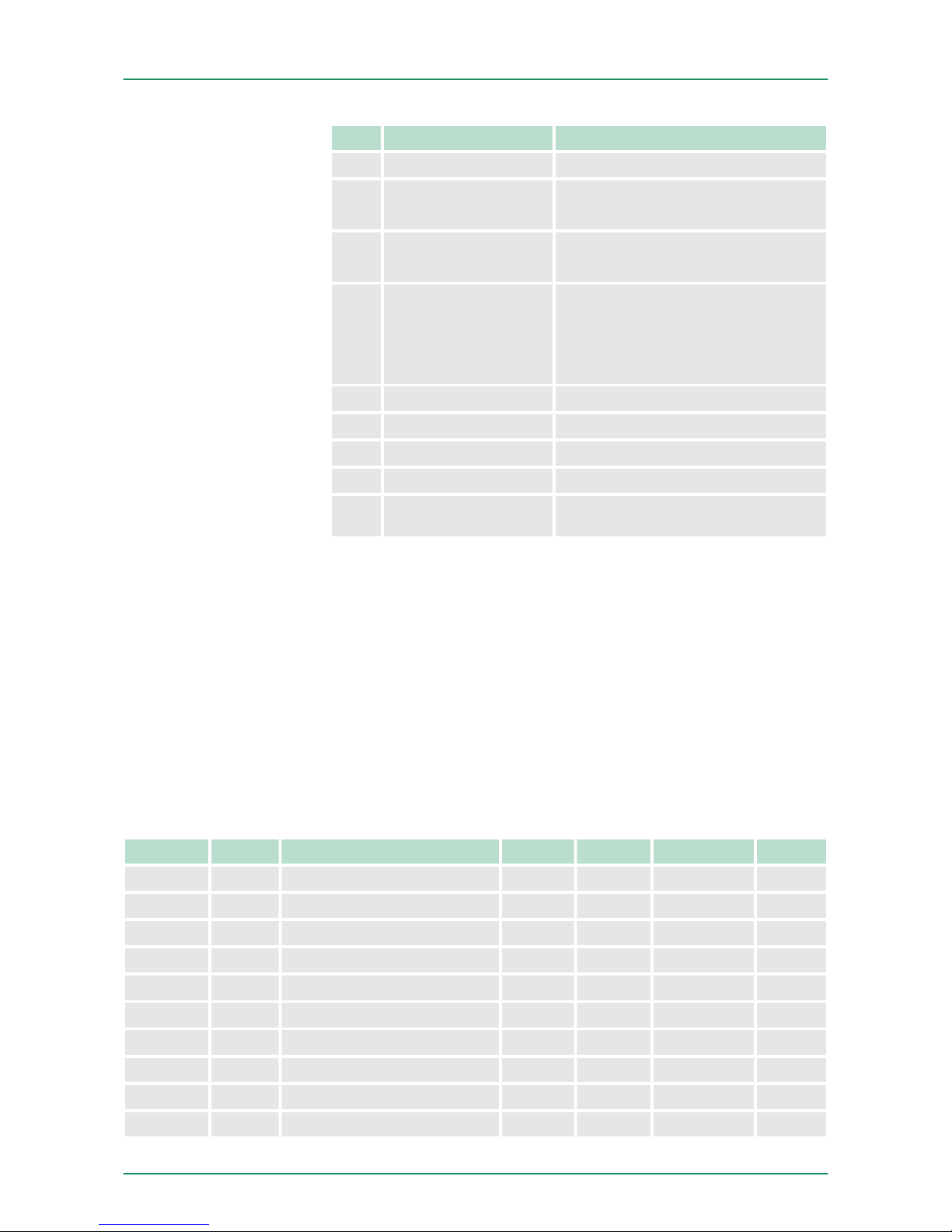
Bit Name Function
2 SW_GATE_SET sets the software gate
3 ...4- reserved
5 COUNTERVAL_SET sets counter temporarily
to the value of set value
6 RES_SET resets the bits
STS_CMP, STS_END,
STS_OFLW, STS_UFLW
and STS_ZP with edge 0-1
7 - reserved
8 CTRL_SYNC_RESET deactivates the reset mode
9 CTRL_DO_RESET disables the digital output
10 SW_GATE_RESET resets the software gate
11 ...15- reserved
4.3 Parameter data
Via parameterization you may define among others:
n Interrupt behavior
n Input filter
n Counter operating mode res. behavior
DS - Data set for access via CPU, PROFIBUS and PROFINET
IX - Index for access via CANopen
SX - Subindex for access via EtherCAT
Name Bytes Function Default DS IX SX
DIAG_EN 1 Diagnostic interrupt* 00h 00h 3100h 01h
CH0A 1 Input frequency track A 02h 01h 3101h 02h
CH1B 1 Input frequency track B 02h 01h 3102h 03h
CH2L 1 Input frequency Latch 02h 01h 3103h 04h
CH3G 1 Input frequency Gate 02h 01h 3104h 05h
CH4R 1 Input frequency Reset 02h 01h 3105h 06h
CH5 1 reserved 00h 01h 3106h 07h
INT_I 1 Interrupt behavior* 80h 80h 3107h 08h
FCT_I 1 Counter function* 40h 80h 3108h 09h
MODE2_I 1 Counter mode 2* 00h 80h 3109h 0Ah
Parameters
VIPA System SLIO Deployment
Parameter data
HB300 | FM | 050-1BA00 | GB | 14-36 43
Page 44
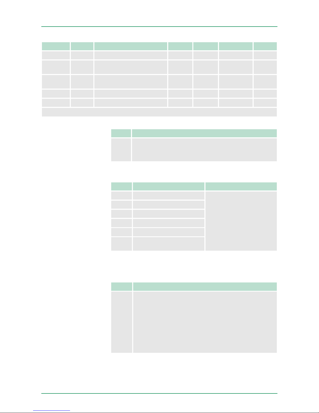
Name Bytes Function Default DS IX SX
MODE3_I 1 Counter mode 3* 00h 80h 310Ah 0Bh
END_I 4 End value 00h 81h 310Bh...
310Eh
0Ch
LOAD_I 4 Load value 00h 81h 310Fh...
3112h
0Dh
HYST_I 1 Hysteresis 00h 81h 3113h 0Eh
PULSE_I 1 Pulse 00h 81h 3114h 0Fh
*) This parameter may only be transferred at STOP state.
Byte Bit 7...0
0 Diagnostic interrupt
n 00h = disable
n 40h = enable
n Here you activate res. de-activate the diagnostic function.
Byte Function Possible values
0 Input frequency track A
n 02h: 100kHz
n 03h: 60kHz
n 04h: 30kHz
n 06h: 10kHz
n 07h: 5kHz
n 08h: 2kHz
n 09h: 1kHz
Other values are not
permissible!
1 Input frequency track B
2 Input frequency Latch
3 Input frequency Gate
4 Input frequency Reset
5 0 (fix)
n Input frequency allows you to preset a filter for I1, I4, I5, I7 and I8.
With the help of filters you may e.g. filter signal peaks at a blurred
input signal.
Byte Bit 7 ... 0
0 Bit 6 ... 0: Interrupt behavior
n Bit 0: Proc. interrupt HW gate open
n Bit 1: Proc. interrupt HW gate closed
n Bit 2: Proc. interrupt overflow
n Bit 3: Proc. interrupt underflow
n Bit 4: Proc. interrupt comparison value
n Bit 5: Proc. interrupt end value
n Bit 6: interrupt latch value
n Bit 7: 1 (fix)
n Setting the appropriate bit activates the associated process inter-
rupt
DIAG_EN Diagnostic
interrupt
CHxx Input frequency
INT_I Interrupt behavior
VIPA System SLIODeployment
Parameter data
HB300 | FM | 050-1BA00 | GB | 14-36 44
Page 45

Byte Bit 7 ... 0
0
n Bit 5 ... 0:Counter function
– 000000b = count endless
– 000001b = once: forward
– 000010b = once: backwards
– 000100b = once: no main direction
– 001000b = periodic: forward
– 010000b = periodic: backwards
– 100000b = periodic: no main direction
n Bit 6: 1 (fix)
n Bit 7: 0 (fix)
Byte Bit 7 ... 0
0
n Bit 2 ... 0: Output set (... when following condition is
met)
– 000b = never
– 001b = counter value ³ comparison value
– 010b = counter value £ comparison value
– 100b = counter value = comparison value
n Bit 3: Counter direction track B inverted
– 0 = No (not inverted)
– 1 = Yes (inverted)
n Bit 6 ... 4: Reset
– 000b = de-activated
– 001b = high level
– 011b = edge 0-1
– 101b = edge 0-1 once
n Bit 7: 0 (fix)
n For activation of the output the bit CTRL_DO_SET (bit 1) of the
control word must be set!
n For activation of reset the bit CTRL_SYNC_SET (bit 0) of the con-
trol word must be set!
Byte Bit 7 ... 0
0
n Bit 2 ... 0: Signal evaluation
– 000b = Counter de-activated
– 001b = Rotary encoder single (at A and B)
– 010b = Rotary encoder double (at A and B)
– 011b = Rotary encoder quadruple (at A and B)
– 100b = Direction (pulse at A and direction at B)
n Bit 6 ... 3: HW gate
– 0000b = de-activated
– 0001b = activated
n Bit 7: Gate function (internal gate)
– 0 = abort
– 1 = interrupt
n At de-activated counter the further parameter settings are ignored.
n With de-activated HW gate the counter starts by setting SW gate.
FCT_I Counter function
MODE2_I Counter mode
2
MODE3_I Counter mode
3
VIPA System SLIO Deployment
Parameter data
HB300 | FM | 050-1BA00 | GB | 14-36 45
Page 46

n With activated HW gate activate a high level at gate the HW gate.
The counter may only start when HW gate and SW gate are set.
n With gate function "abort" counting begins again at the load value.
With "interrupt" counting is continued with the count.
You may set an upper and a lower limit by setting a load value as
start and an end value.
The hysteresis serves the avoidance of many toggle processes of the
output and/or the interrupt, if the counter value is in the range of the
comparison value. You may set a range of 0 to 255. The settings 0
and 1 deactivate the hysteresis. The hysteresis influences zero run,
comparison, over- and underflow.
The pulse duration tells for what time the output is set when the parameterized comparison criterion is reached. The pulse duration can be
set in steps of 2.048ms between 0 and 522.24ms. If the pulse dura-
tion = 0, the output is set active until the comparison condition is not
longer fulfilled.
4.4 Counter - Functions
You may count forward and backwards and choose between the following counter functions:
n Count endless, e.g. distance measuring with incremental encoder
n Count once, e.g. count to a maximum limit
n Count periodic, e.g. count with repeated counter process
In the operating modes "Count once" and "Count periodic" you may
define a counter range as start and end value via the parameterization. For every counter additional parameterizable functions are available like gate function, comparison, hysteresis and process interrupt.
Via the parameterization you have the opportunity to define a main
counting direction for every counter. If "none" is chosen, the complete
counting range is available:
Limits Valid value range
Lower count limit
-2 147 483 648 (-231)
Upper count limit
+2 147 483 647 (231-1)
Main counting direction forward
Upper restriction of the count range. The counter counts 0 res. load
value in positive direction until the parameterized end value -1 and
jumps then back to the load value with the next following encoder
pulse.
Main counting direction backwards
Lower restriction of the count range. The counter counts from the parameterized start- res. load value in negative direction to the parameterized end value +1 and jumps then back to the start value with the
next following encoder pulse.
END_I,LOAD_I End
value, Load value
HYST_I Hysteresis
PULSE_I Pulse (duration)
Overview
Main counting direction
VIPA System SLIODeployment
Counter - Functions
HB300 | FM | 050-1BA00 | GB | 14-36 46
Page 47
If the HW gate is enabled, only the HW gate may be influenced by the
gate functions. An opening and closing of the SW gate only interrupts
the count process.
Abort count process
The count process starts after closing and restart of the gate beginning with the load value.
Interrupt count process
The count process continuous after closing and restart of the gate
beginning with the last recent counter value.
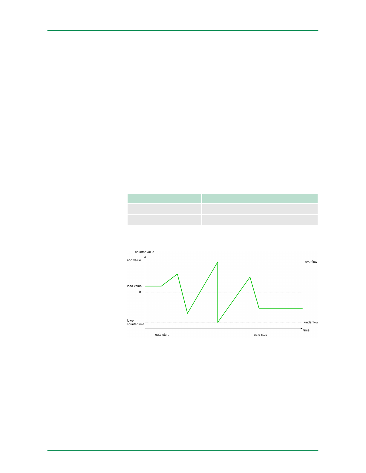
In this operating mode, the counter counts from the load value. When
the counter counts forward and reaches the upper count limit and
another counting pulse in positive direction arrives, it jumps to the
lower count limit and counts from there on. When the counter counts
backwards and reaches the lower count limit and another counting
pulse in negative direction arrives, it jumps to the upper count limit
and counts from there on. The count limits are set to the maximum
count range.
Limits Valid value range
Lower count limit
-2 147 483 648 (-231)
Upper count limit
+2 147 483 647 (231-1)
With overflow or underflow the status bits STS_OFLW respectively
STS_UFLW are set. These bits remain set until these are reset with
RES_STS. If enabled additionally a process interrupt is triggered.
No main counting direction
n The counter counts once starting with the load value.
n You may count forward or backwards.
n The count limits are set to the maximum count range.
n At over- or underflow at the count limits, the counter jumps to the
according other count limit and the internal gate is automatically
closed and the status bits STS_OFLW respectively STS_UFLW
are set. If enabled additionally a process interrupt is triggered.
n To restart the count process, you have to re-open the internal
gate.
Gate function abort/
interrupt
Count continuously
Count Once
VIPA System SLIO Deployment
Counter - Functions
HB300 | FM | 050-1BA00 | GB | 14-36 47
Page 48
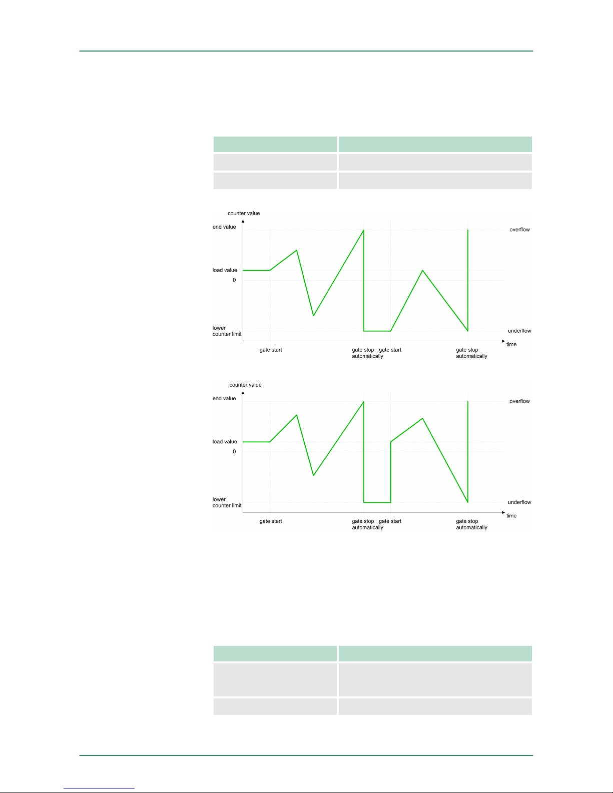
n At interrupting gate control, the count process continuous with the
last recent counter value.
n At aborting gate control, the counter starts with the load value.
Limits Valid value range
Lower count limit
-2 147 483 648 (-231)
Upper count limit
+2 147 483 647 (231 -1)
Interrupting gate control:
Aborting gate control:
Main counting direction forward
n The counter counts starting with the load value.
n When the counter reaches the end value -1 in positive direction, it
jumps to the load value at the next positive count pulse and the
gate is automatically closed.
n To restart the count process, you must create a positive edge of
the gate. The counter starts with the load value.
Limits Valid value range
Limit value
-2 147 483 647 (-231 +1)
to +2 147 483 647 (231 -1)
Lower count limit
-2 147 483 648 (-231)
VIPA System SLIODeployment
Counter - Functions
HB300 | FM | 050-1BA00 | GB | 14-36 48
Page 49
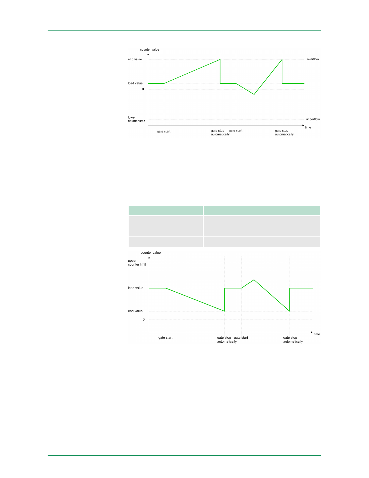
Main counting direction backwards
n The counter counts backwards starting with the load value.
n When the counter reaches the end value +1 in negative direction,
it jumps to the load value at the next negative count pulse and the
gate is automatically closed.
n To restart the count process, you must create a positive edge of
the gate. The counter starts with the load value.
Limits Valid value range
Limit value
-2 147 483 648 (-231)
to +2 147 483 646 (231 -2)
Upper count limit
+2 147 483 647 (231 -1)
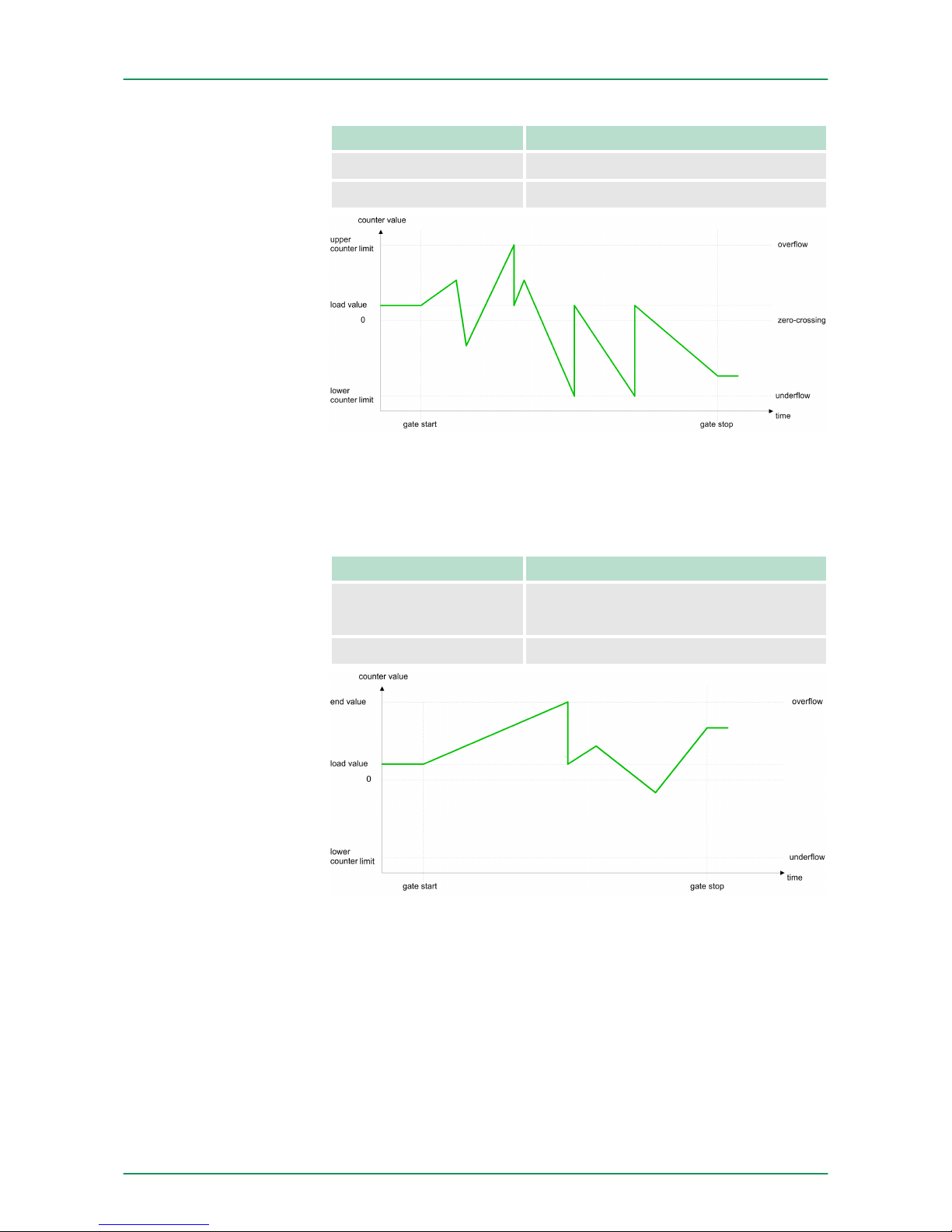
No main counting direction
n The counter counts forward or backwards starting with the load
value.
n At over- or underrun at the count limits, the counter jumps to the
according other count limit and counts from there on.
n The count limits are set to the maximum count range.
Count Periodically
VIPA System SLIO Deployment
Counter - Functions
HB300 | FM | 050-1BA00 | GB | 14-36 49
Page 50
Limits Valid value range
Lower count limit
-2 147 483 648 (-231)
Upper count limit
+2 147 483 647 (231 -1)
Main counting direction forward
n The counter counts forward starting with the load value.
n When the counter reaches the end value –1 in positive direction, it
jumps to the load value at the next positive count pulse.
Limits Valid value range
Limit value
-2 147 483 647 (-231 +1)
to +2 147 483 647 (231 -1)
Lower count limit
-2 147 483 648 (-231)
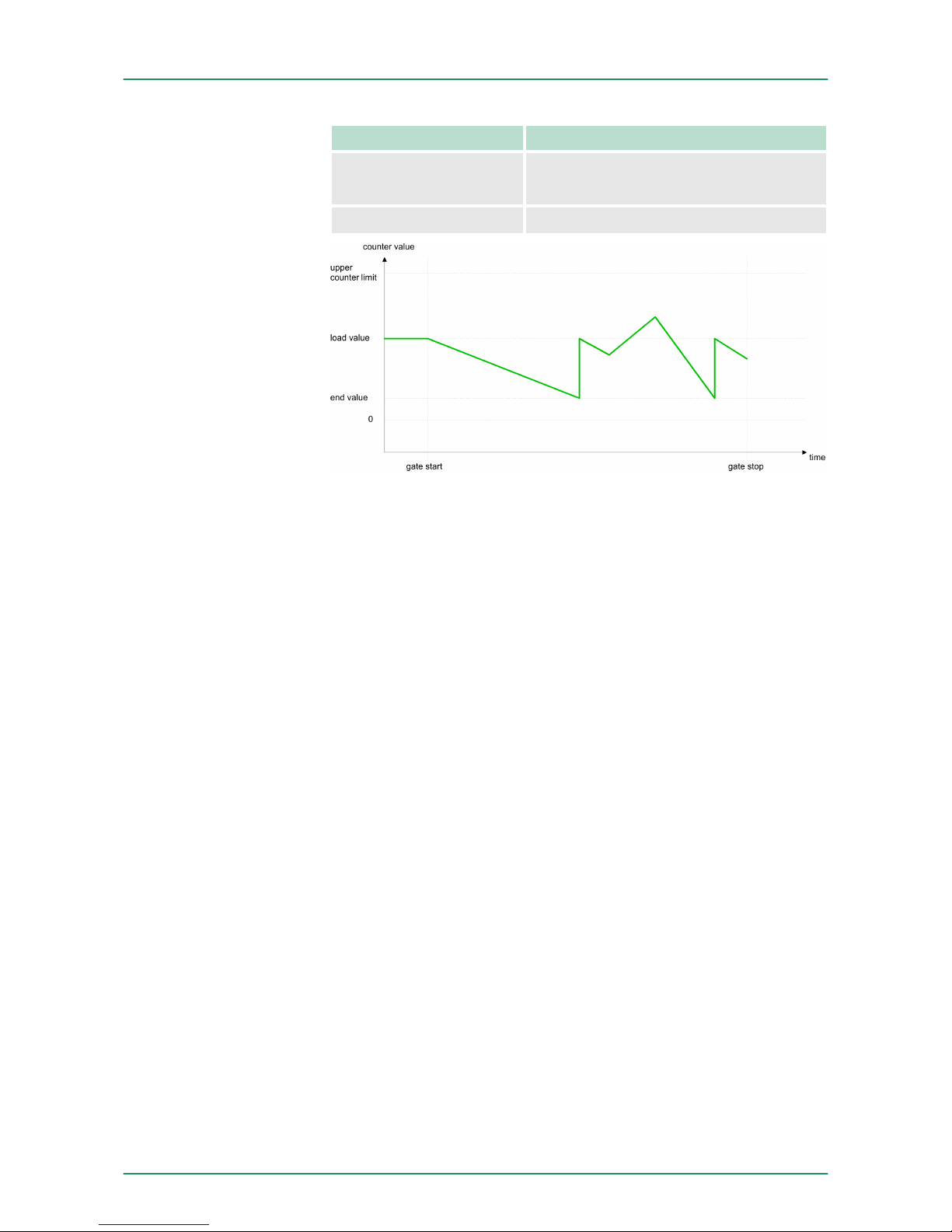
Main counting direction backwards
n The counter counts backwards starting with the load value.
n When the counter reaches the end value +1 in negative direction,
it jumps to the load value at the next negative count pulse.
n You may exceed the upper count limit.
VIPA System SLIODeployment
Counter - Functions
HB300 | FM | 050-1BA00 | GB | 14-36 50
Page 51
Limits Valid value range
Limit value
-2 147 483 648 (-231)
to +2 147 483 646 (231 -2)
Upper count limit
+2 147 483 647 (231 -1)
4.5 Counter additional functions
The following additional functions may be set for the counter via the
parameterization of the 050-1BA00:
n Gate function:
– The gate function serves for the start, stop and interrupt of a
count function.
n Latch function:
– An edge 0-1 at the digital input "Latch" stores the recent
counter value in the latch register.
n Comparison:
– You may set a comparison value that activates res. de-acti-
vates the digital output res. releases a process interrupt
depending on the counter value.
n Hysteresis:
– The setting of a hysteresis for example serves the avoidance
of many toggle processes of the output and/or the interrupt,
when the value of an encoder signal shifts around a compar-
ison value.
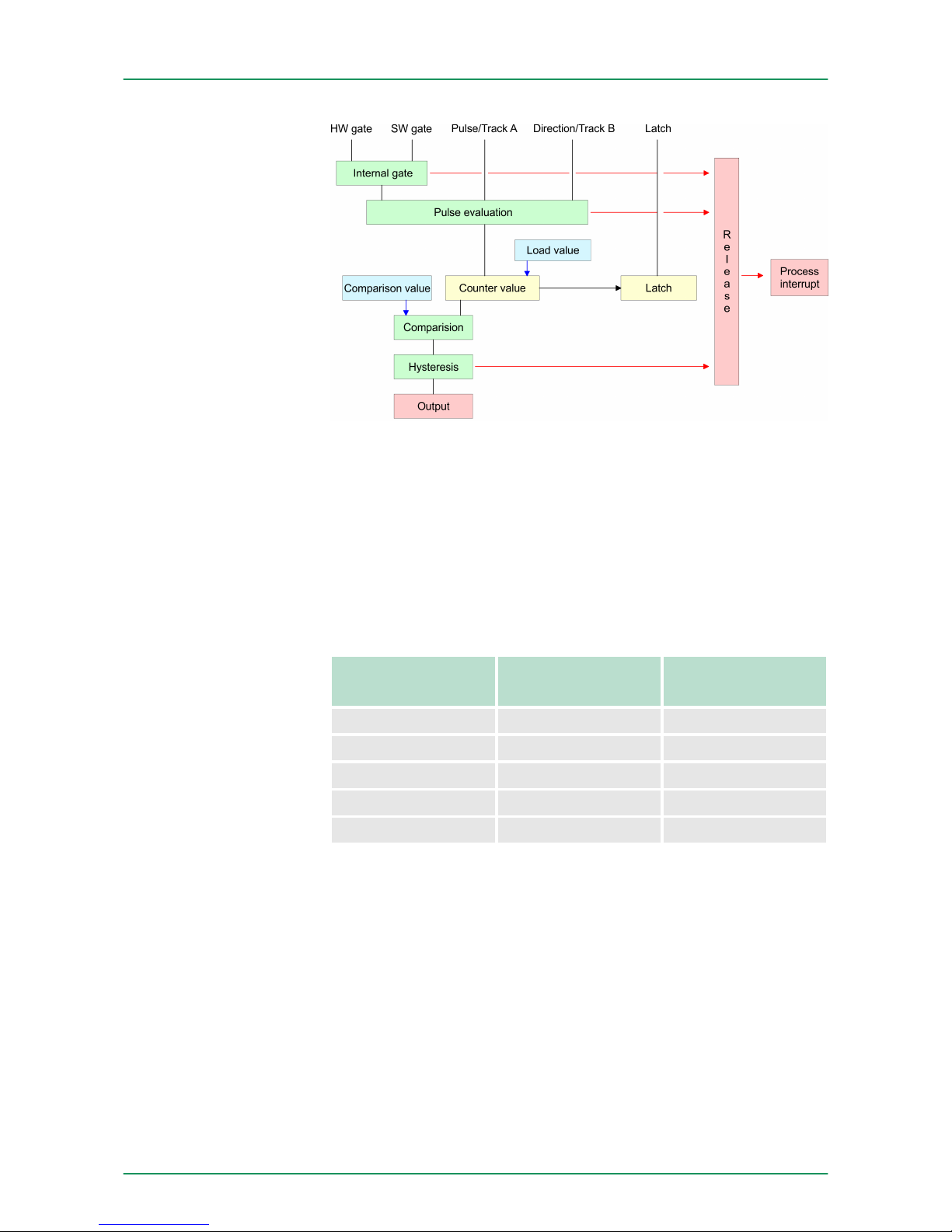
The illustration shows how the additional functions influence the
counting behavior. The following pages describe these functions in
detail:
Overview
Schematic structure
VIPA System SLIO Deployment
Counter additional functions
HB300 | FM | 050-1BA00 | GB | 14-36 51
Page 52
The activation res. de-activation of the counter happens via an
internal gate (I gate). The I gate is the AND operation of the software
gate (SW gate) and the hardware gate (HW gate). The SW gate is
opened (activated) via your user application by an edge 0-1 of the bit
SW_GATE_SET of CCTRL_I in the output area. The software gate is
closed (de-activated) by an edge 0-1 of the bit SW_GATE_RESET.
The HW gate is controlled via the concerning "Gate" input. The
parameterization allows you to de-activate the consideration of the
HW gate so that the counter activation can take place only via the SW
gate. The following states influence the I gate:
SW gate HW gate influences
I gate
0 with edge 0-1 0
1 with edge 0-1 1
with edge 0-1 1 1
with edge 0-1 0 0
with edge 0-1 de-activated 1
Gate function abort and interrupt
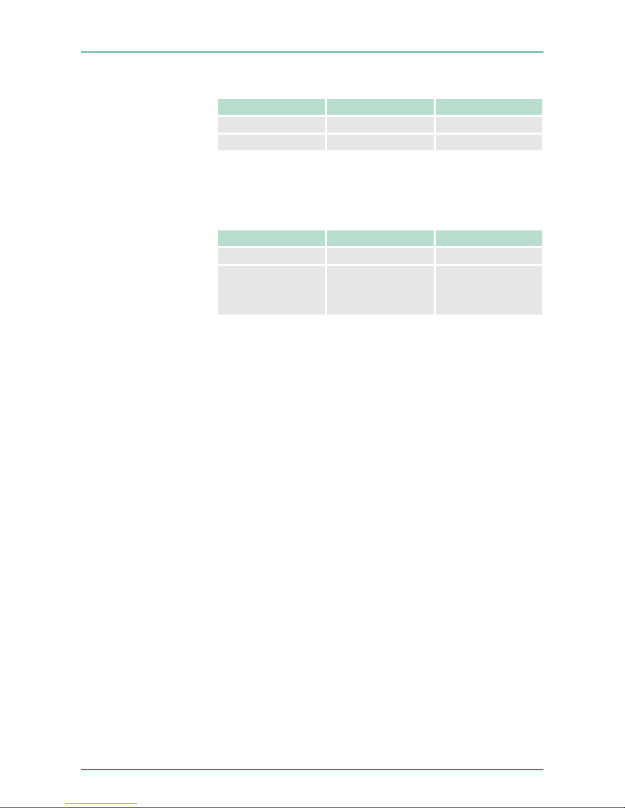
The parameterization defines if the gate interrupts or aborts the
counter process.
n At abort function the counter starts counting with the load value
after gate restart.
Gate function
VIPA System SLIODeployment
Counter additional functions
HB300 | FM | 050-1BA00 | GB | 14-36 52
Page 53
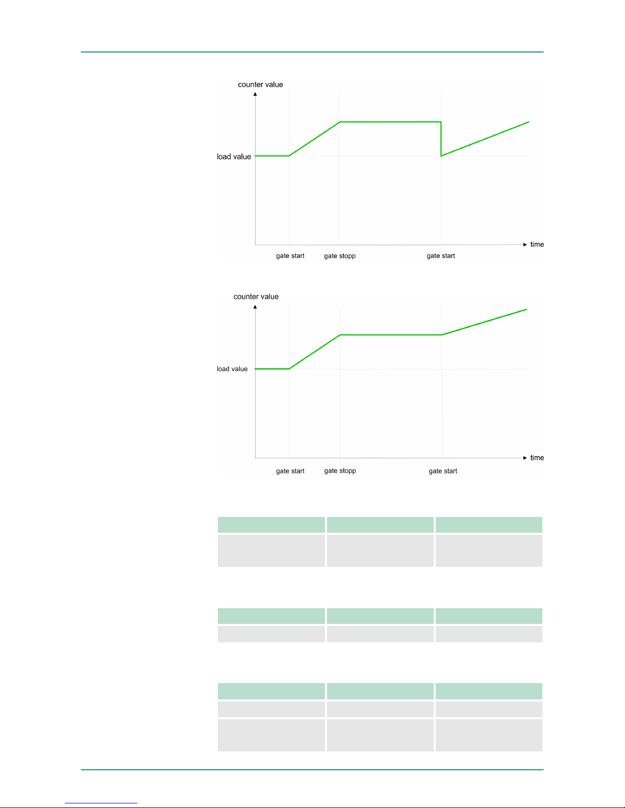
n At interrupt function, the counter starts counting with the recent
counter value after gate restart.
Gate control via SW gate, aborting
SW gate HW gate Reaction Counter
edge 0-1 de-activated Restart with
load value
Gate control via SW gate, interrupting
SW gate HW gate Reaction Counter
edge 0-1 de-activated Continue
Gate control via SW/HW gate, aborting
SW gate HW gate Reaction Counter
edge 0-1 1 Continue
1 edge 0-1 Restart with
load value
Gate control abort,
interruption
VIPA System SLIO Deployment
Counter additional functions
HB300 | FM | 050-1BA00 | GB | 14-36 53
Page 54
Gate control via SW/HW gate, interrupting
SW gate HW gate Reaction Counter
edge 0-1 1 Continue
1 edge 0-1 Continue
Gate control via SW/HW gate, operating mode "Count once": If the
internal gate has been closed automatically it may only be opened
again under the following conditions:
SW gate HW gate Reaction I gate
1 edge 0-1 1
edge 0-1
(after edge 0-1
at HW gate)
1 1
As soon as during a count process an edge 0-1 is recognized at the
"Latch" input of the counter, the recent counter value is stored in the
latch register. You may access the latch register via the input area.
After a STOP-RUN transition latch is always 0.
The compare value is to be pre-defined by CC_I. As soon as a comparison condition is kept, the bit STS_DO of the counter status is set.
Please consider that the bit STS_DO may only be influenced when in
the counter status the bit STS_CTRL_DO is set. You pre-define the
behavior of the counter output via the parameterization (MODE2_I):
n output never switches
n output switches when counter value ³ comparison value
n output switches when counter value £ comparison value
n output switches at comparison value
Output never switches
The output never switches.
Output switches when counter value ³ comparison value
The output remains set as long as the counter value is higher or
equal comparison value.
Output switches when counter value
£
comparison value
The output remains set as long as the counter value is lower or equal
comparison value.
Pulse at comparison value
When the counter reaches the comparison value the output is set for
the parameterized pulse duration. If the pulse duration = 0 the output
is set until the comparison condition is no longer met. When you've
set a main counting direction the output is only set at reaching the
comparison value from the main counting direction.
Pulse duration
Gate control "Count
once"
Latch function
Comparison
VIPA System SLIODeployment
Counter additional functions
HB300 | FM | 050-1BA00 | GB | 14-36 54
Page 55
The pulse duration defines how long the output is set. It may be
preset in steps of 2.048ms between 0 and 522.24ms. The pulse dura-
tion starts with the setting of the according digital output. The inaccuracy of the pulse duration is less than 2.048ms. There is no past
triggering of the pulse duration when the comparison value has been
left and reached again during pulse output.
The bit STS_DO is set together with the bit STS_CMP in
the counter status. In contrast to the bit STS_DO this bit
remains set as long as it is reset by setting the bit
RES_SET in the control word.
n The hysteresis serves the avoidance of many toggle processes of
the output and the interrupt, if the counter value is in the range of
the comparison value.
n For the hysteresis you may set a range of 0 to 255.
n The settings 0 and 1 deactivate the hysteresis.
n The hysteresis influences zero run, comparison, over- and under-
flow.
n An activated hysteresis remains active after a change. The new
hysteresis range is activated with the next hysteresis event.
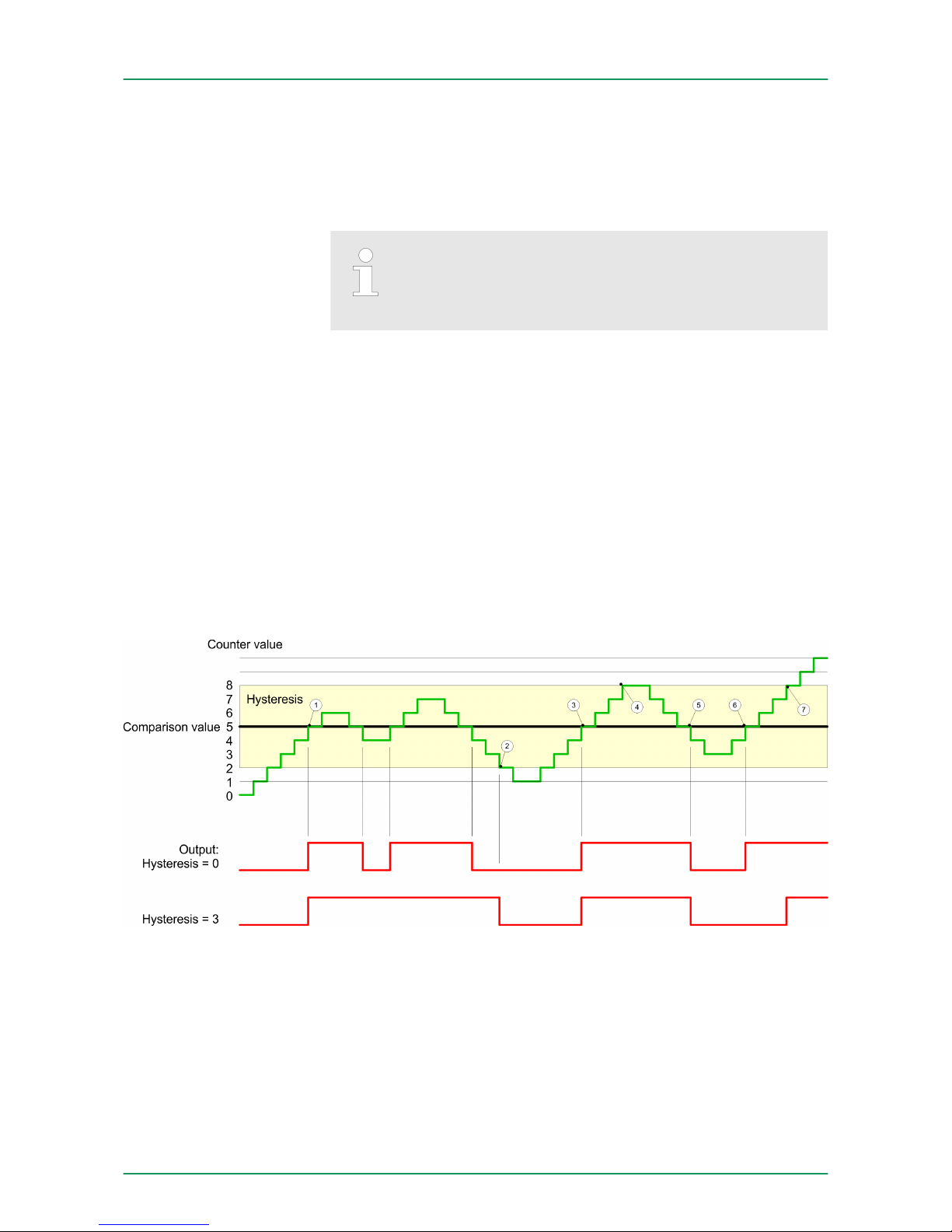
The following pictures illustrate the output behavior for hysteresis 0
and hysteresis 3 for the according conditions:
1 Counter value ³ comparison value ® output is set and hysteresis
activated
2 Leave hysteresis range ® output is reset
3 Counter value ³ comparison value ® output is set and hysteresis
activated
4 Leave hysteresis range, output remains set for counter value ³
comparison value
5 counter value < comparison value and hysteresis active ® output
is reset
6 counter value ³ comparison value ® output is not set for hyste-
resis active
7 Leave hysteresis range, output remains set for counter value ³
comparison value
Hysteresis
Effect at counter value
³
comparison value
VIPA System SLIO Deployment
Counter additional functions
HB300 | FM | 050-1BA00 | GB | 14-36 55
Page 56
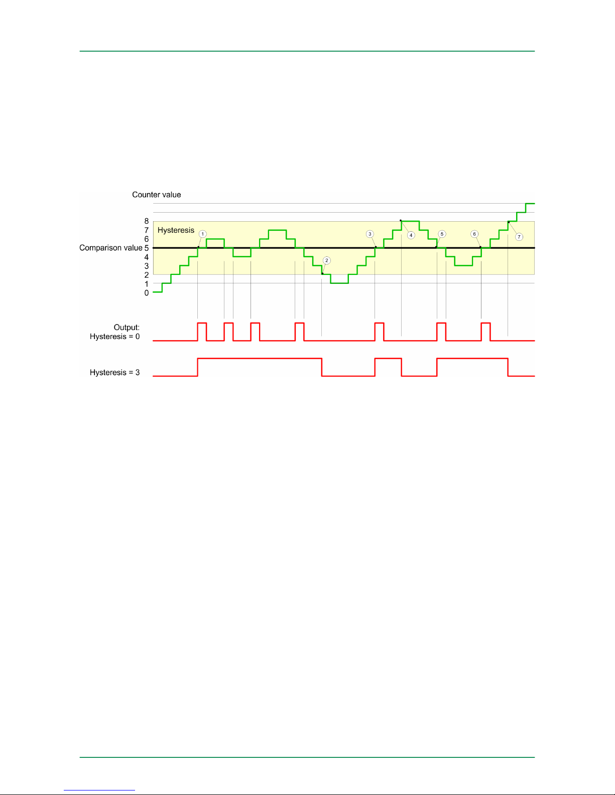
With reaching the comparison condition the hysteresis gets active. At
active hysteresis the comparison result remains unchanged until the
counter value leaves the set hysteresis range. After leaving the hysteresis range a new hysteresis is only activated with again reaching the
comparison conditions.
1 Counter value = comparison value ® output is set and hysteresis
activated
2 Leave hysteresis range ® output is reset and counter value <
comparison value
3 Counter value = comparison value ® output is set and hysteresis
activated
4 Output is reset for leaving hysteresis range and counter value >
comparison value
5 Counter value = comparison value ® output is set and hysteresis
activated
6 Counter value = comparison value and hysteresis active ® output
remains set
7 Leave hysteresis range and counter value > comparison value ®
output is reset
With reaching the comparison condition the hysteresis gets active. At
active hysteresis the comparison result remains unchanged until the
counter value leaves the set hysteresis range. After leaving the hysteresis range a new hysteresis is only activated with again reaching the
comparison conditions.
Effect at pulse at comparison value with
pulse duration Zero
VIPA System SLIODeployment
Counter additional functions
HB300 | FM | 050-1BA00 | GB | 14-36 56
Page 57
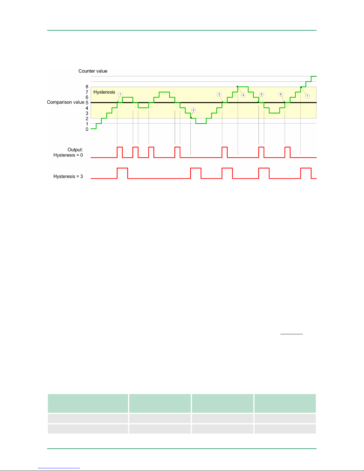
1 Counter value = comparison value ® pulse of the parameterized
pulse duration is put out, the hysteresis is activated and the
counting direction stored
2 Leaving the hysteresis range contrary to the stored counting direc-
tion ® pulse of the parameterized pulse duration is put out, the
hysteresis is de-activated
3 Counter value = comparison value ® pulse of the parameterized
pulse duration is put out, the hysteresis is activated and the
counting direction stored
4 Leaving the hysteresis range without changing counting direction
® hysteresis is de-activated
5 Counter value = comparison value ® pulse of the parameterized
pulse duration is put out, the hysteresis is activated and the
counting direction stored
6 Counter value = comparison value and hysteresis active ® no
pulse
7 Leaving the hysteresis range contrary to the stored counting direc-
tion ® pulse of the parameterized pulse duration is put out, the
hysteresis is de-activated
With reaching the comparison condition the hysteresis gets active
and a pulse of the parameterized duration is put out. As long as the
counter value is within the hysteresis range, no other pulse is put out.
With activating the hysteresis the counting direction is stored in the
module. If the counter value leaves the hysteresis range contrary to
the stored counting direction, a pulse of the parameterized duration is
put out. Leaving the hysteresis range without direction change, no
pulse is put out.
4.6 Diagnostic and interrupt
Event Process interrupt Diagnostics
interrupt
parameterizable
HW gate open X - X
HW gate closed X - X
Effect at pulse at comparison value with
pulse duration not zero
Overview
VIPA System SLIO Deployment
Diagnostic and interrupt
HB300 | FM | 050-1BA00 | GB | 14-36 57
Page 58
Event Process interrupt Diagnostics
interrupt
parameterizable
Overflow X - X
Underflow X - X
Comparison value X - X
End value X - X
Latch value X - X
Diagnostics buffer overflow - X -
Process interrupt lost - X X
Overload at output - X X
So you may react to asynchronous events, there is the possibility to
activate a process interrupt. A process interrupt interrupts the linear
program sequence and jumps depending on the master system to a
corresponding Interrupt routine. Here you can react to the process
interrupt accordingly.
With CANopen the process interrupt data are transferred via an emergency telegram. Operating with CPU, PROFIBUS and PROFINET the
process interrupt data were transferred via diagnostics telegram.
SX - Subindex for access via EtherCAT.
Name Bytes Function Default SX
PRIT_A 1 Process interrupt data 00h 02h
PRIT_B 1 State of the inputs 00h 03h
PRIT_US 2 µs ticker 00h 04h ...
05h
Byte Bit 7 ... 0
0 Process interrupt data
n Bit 0: HW gate opened
n Bit 1: HW gate closed
n Bit 2: Overflow, underflow or end value reached
n Bit 3: Comparison value reached
n Bit 4: Latch value reached
n Bit 7 ... 5 reserved
Process interrupt
PRIT_A Process interrupt data
VIPA System SLIODeployment
Diagnostic and interrupt
HB300 | FM | 050-1BA00 | GB | 14-36 58
Page 59
Byte Bit 7 ... 0
0 State of the inputs at the moment of the process interrupt
n Bit 0: Input value channel 0 (TrackA)
n Bit 1: Input value channel 1 (TrackB)
n Bit 2: Input value channel 2 (Latch)
n Bit 3: Input value channel 3 (HW gate)
n Bit 4: Input value channel 4 (Reset)
n Bit 7 ... 5 reserved
Byte Bit 7 ... 0
0 ... 1 Value of the µs ticker at the moment
of the process interrupt
µs ticker
In the SLIO module there is a timer (µs ticker). With PowerON the
timer starts counting with 0. After 216-1µs the timer starts with 0 again.
Via the parameterization you may activate a diagnostic interrupt for
the module. With a diagnostic interrupt the module serves for diagnostic data for diagnostic interrupt
incoming
. As soon as the reason for
releasing a diagnostic interrupt is no longer present, the diagnostic
interrupt
going
automatically takes place. All events of a channel
between diagnostic interrupt
incoming
and diagnostic interrupt
going
are not
stored and get lost. Within this time window (1. diagnostic interrupt
incoming
until last diagnostic interrupt
going
) the MF-LED of the
module is on.
DS - Record set for access via CPU, Profibus and ProfiNET. The
access happens by DS 01h. Additionally the first 4 bytes may
be accessed by DS 00h.
IX - Index for access via CANopen. The access happens by IX
2F01h. Additionally the first 4 bytes may be accessed by IX
2F00h.
SX - Subindex for access via EtherCAT.
Name Bytes Function Default DS IX SX
ERR_A 1 Diagnostic 00h 01h 2F01h 02h
MODTYP 1 Module information 18h 03h
ERR_C 1 reserved 00h 04h
ERR_D 1 Diagnostic 00h 05h
CHTYP 1 Channel type 76h 06h
NUMBIT 1 Number diagnostics bits
per channel
08h 07h
NUMCH 1 Number channels
of the module
01h 08h
PRIT_B State of the
inputs
PRIT_US µs ticker
Diagnostic data
VIPA System SLIO Deployment
Diagnostic and interrupt
HB300 | FM | 050-1BA00 | GB | 14-36 59
Page 60
Name Bytes Function Default DS IX SX
CHERR 1 Channel error 00h 09h
CH0ERR 1 Channel-specific error 00h 0Ah
CH1ERR…
CH7ERR
7 reserved 00h 0Bh ...
11h
DIAG_US 4 µs ticker 00h 12h
Byte Bit 7 ... 0
0
n Bit 0: set at module failure
n Bit 1: reserved
n Bit 2: set at external error
n Bit 3: set at channel error
n Bit 4: set at overload at output
n Bit 7 ... 5: reserved
Byte Bit 7 ... 0
0
n Bit 3 ... 0: Module class
– 1000b: Function module
n Bit 4: set at channel information present
n Bit 7 ... 5: reserved
Byte Bit 7 ... 0
0 reserved
Byte Bit 7 ... 0
0
n Bit 2 ... 0: reserved
n Bit 3: set at internal diagnostics buffer overflow
n Bit 5 ... 4: reserved
n Bit 6: Process interrupt lost
n Bit 7: reserved
Byte Bit 7 ... 0
0
n Bit 6 ... 0: Channel type
– 76h: Counter module
n Bit 7: reserved
Byte Bit 7 ... 0
0 Number of diagnostics bits of the module per channel
(here 08h)
ERR_A Diagnostic
MODTYP Modul information
ERR_C reserved
ERR_D Diagnostic
CHTYP Channel type
NUMBIT Diagnostic bits
VIPA System SLIODeployment
Diagnostic and interrupt
HB300 | FM | 050-1BA00 | GB | 14-36 60
Page 61

Byte Bit 7 ... 0
0 Number of channels of the module (here 01h)
Byte Bit 7 ... 0
0
n Bit 0: set at error in channel group 0
n Bit 7 ... 1: reserved
Byte Bit 7 ... 0
0 Diagnostic interrupt due to process interrupt lost at ...
n Bit 0: Hardware gate open
n Bit 1: Hardware gate closed
n Bit 2: Overflow/underflow/end value
n Bit 3: Comparison value reached
n Bit 4: Latch value stored
n Bit 7 ... 5: reserved
Byte Bit 7 ... 0
0 reserved
Byte Bit 7 ... 0
0 ... 3 Value of the µs ticker at the moment of the diagnostic
µs ticker
In the SLIO module there is a timer (µs ticker). With PowerON the
timer starts counting with 0. After 232-1µs the timer starts with 0 again.
NUMCH Channels
CHERR Channel error
CH0ERR channel-specific
CH1ERR ... CH7ERR
reserved
DIAG_US µs ticker
VIPA System SLIO Deployment
Diagnostic and interrupt
HB300 | FM | 050-1BA00 | GB | 14-36 61
 Loading...