

Page 1

PPC | 67K-RRJ0 | Manual
HB160 | PPC | 67K-RRJ0 | en | 18-30
VIPA HMI
Panel PC - PPC010 EC
www.vipa.com/en/service-support/manuals
Page 2

67K-RRJ0_000_PPC010EC,1,EN -
© 2018
VIPA GmbH
Ohmstr
. 4
91074 Herzogenaurach
Telephone: +49 9132 744-0
Fax: +49 9132 744-1864
Email: [email protected]
Internet: www.vipa.com
Page 3

Table of contents
1 General.................................................................................................................... 4
1.1 Copyright © VIP
A GmbH ................................................................................. 4
1.2 About this manual............................................................................................. 5
1.3 Safety information............................................................................................. 6
2 Hardware description............................................................................................. 7
2.1 Safety information for users.............................................................................. 7
2.2 Properties......................................................................................................... 8
2.3 Structure........................................................................................................... 9
2.3.1 Overview........................................................................................................ 9
2.3.2 Interfaces..................................................................................................... 11
2.3.3 Memory management.................................................................................. 15
2.4 Dimensions..................................................................................................... 16
2.5 General data................................................................................................... 17
2.6 Technical data................................................................................................. 19
3 Deployment Panel PC.......................................................................................... 22
3.1 Installation...................................................................................................... 22
3.2 Installation of the CFast card.......................................................................... 23
3.3 Commissioning............................................................................................... 24
3.3.1 Firmware update.......................................................................................... 24
3.3.2 VIPA Startup-Manager................................................................................. 25
3.4 Connection to a PLC system.......................................................................... 28
3.5 Operating system Windows Embedded Compact 7....................................... 29
3.5.1 General........................................................................................................ 29
3.5.2 Structure...................................................................................................... 30
3.6 Integrated server............................................................................................ 32
3.6.1 General........................................................................................................ 32
3.6.2 ftp server...................................................................................................... 33
3.6.3 Telnet server................................................................................................ 34
3.6.4 VNC server.................................................................................................. 35
3.7 Access to the network resources.................................................................... 37
4 BIOS setup............................................................................................................ 38
4.1 Overview......................................................................................................... 38
4.2 Main................................................................................................................ 39
4.3 Advanced........................................................................................................ 40
4.4 Chipset........................................................................................................... 50
4.5 Security........................................................................................................... 54
4.6 Boot................................................................................................................ 56
4.7 Save and Exit................................................................................................. 57
5 Installation guidelines.......................................................................................... 59
5.1 Basic rules for the EMC-equitable assembly of installations.......................... 59
5.2 EMC-equitable assembly................................................................................ 62
5.3 EMC-equitable cabling................................................................................... 63
5.4 Special precautions providing high noise immunity........................................ 66
5.5 Checklist for the EMC-compliant installation of controllers............................. 67
Appendix............................................................................................................... 68
A History of changes............................................................................................ 70
VIPA HMI
Table of contents
HB160 | PPC | 67K-RRJ0 | en | 18-30 3
Page 4

1 General
1.1 Copyright © VIPA GmbH
This document contains proprietary information of VIPA and is not to be disclosed or used
except in accordance with applicable agreements.
This material is protected by the copyright laws. It may not be reproduced, distributed, or
altered in any fashion by any entity (either internal or external to VIPA), except in accordance with applicable agreements, contracts or licensing, without the express written consent of VIPA and the business management owner of the material.
For permission to reproduce or distribute, please contact: VIPA, Gesellschaft für Visualisierung und Prozessautomatisierung mbH Ohmstraße 4, D-91074 Herzogenaurach, Germany
Tel.: +49 9132 744 -0
Fax.: +49 9132 744-1864
EMail: [email protected]
http://www.vipa.com
Every effort has been made to ensure that the information contained in
this document was complete and accurate at the time of publishing. Nevertheless, the authors retain the right to modify the information.
This customer document describes all the hardware units and functions
known at the present time. Descriptions may be included for units which
are not present at the customer site. The exact scope of delivery is
described in the respective purchase contract.
Hereby, VIPA GmbH declares that the products and systems are in compliance with the
essential requirements and other relevant provisions. Conformity is indicated by the CE
marking af
fixed to the product.
For more information regarding CE marking and Declaration of Conformity (DoC), please
contact your local VIPA customer service organization.
VIPA, SLIO, System 100V, System 200V, System 300V, System 300S, System 400V,
System 500S and Commander Compact are registered trademarks of VIPA Gesellschaft
für Visualisierung und Prozessautomatisierung mbH.
SPEED7 is a registered trademark of profichip GmbH.
SIMATIC, STEP, SINEC, TIA Portal, S7-300, S7-400 and S7-1500 are registered trademarks of Siemens AG.
Microsoft and Windows are registered trademarks of Microsoft Inc., USA.
Portable Document Format (PDF) and Postscript are registered trademarks of Adobe
Systems, Inc.
All other trademarks, logos and service or product marks specified herein are owned by
their respective companies.
All Rights Reserved
CE Conformity Declaration
Conformity Information
Trademarks
VIPA HMI
General
Copyright © VIP
A GmbH
HB160 | PPC | 67K-RRJ0 | en | 18-30
4
Page 5

Contact your local VIPA Customer Service Organization representative if you wish to
report errors or questions regarding the contents of this document. If you are unable to
locate a customer service centre, contact VIP
A as follows:
VIPA GmbH, Ohmstraße 4, 91074 Herzogenaurach, Germany
Telefax: +49 9132 744-1204
EMail: [email protected]
Contact your local VIPA Customer Service Organization representative if you encounter
problems with the product or have questions regarding the product. If you are unable to
locate a customer service centre, contact VIPA as follows:
VIPA GmbH, Ohmstraße 4, 91074 Herzogenaurach, Germany
Tel.: +49 9132 744-1150 (Hotline)
EMail: [email protected]
1.2 About this manual
This manual describes the Panel PC 67K-RRJ0-... from VIPA. It contains a description of
the structure, project engineering and deployment.
Product Order number as of state:
HW FW BS
PPC010 EC 67K-RRJ0-... 01 1.0.0
WindowsÒ Embedded Compact 7
The manual is targeted at users who have a background in automation technology.
The manual consists of chapters. Every chapter provides a self-contained description of a
specific topic.
The following guides are available in the manual:
n An overall table of contents at the beginning of the manual
n References with page numbers
The manual is available in:
n printed form, on paper
n in electronic form as PDF-file (Adobe Acrobat Reader)
Important passages in the text are highlighted by following icons and headings:
DANGER!
Immediate or likely danger. Personal injury is possible.
Information product support
Technical support
Objective and contents
Target audience
Structure of the manual
Guide to the document
Availability
Icons Headings
VIPA HMI
General
About this manual
HB160 | PPC | 67K-RRJ0 | en | 18-30 5
Page 6
CAUTION!
Damages to property is likely if these warnings are not heeded.
Supplementary information and useful tips.
1.3 Safety information
The system is constructed and produced for:
n communication and process control
n general control and automation tasks
n industrial applications
n operation within the environmental conditions specified in the technical data
n installation into a cubicle
DANGER!
This device is not certified for applications in
–
in explosive environments (EX-zone)
The manual must be available to all personnel in the
n project design department
n installation department
n commissioning
n operation
CAUTION!
The following conditions must be met before using or commis-
sioning the components described in this manual:
– Hardware modifications to the process control system should only be
carried out when the system has been disconnected from power!
–
Installation and hardware modifications only by properly trained personnel.
– The national rules and regulations of the respective country must be
satisfied (installation, safety, EMC ...)
National rules and regulations apply to the disposal of the unit!
Applications conforming
with specifications
Documentation
Disposal
VIPA HMI
General
Safety information
HB160 | PPC | 67K-RRJ0 | en | 18-30 6
Page 7
2 Hardware description
2.1 Safety information for users
VIPA modules make use of highly integrated components in MOS-Technology. These
components are extremely sensitive to over-voltages that can occur during electrostatic
discharges. The following symbol is attached to modules that can be destroyed by electrostatic discharges.
The Symbol is located on the module, the module rack or on packing material and it indicates the presence of electrostatic sensitive equipment. It is possible that electrostatic
sensitive equipment is destroyed by energies and voltages that are far less than the
human threshold of perception. These voltages can occur where persons do not discharge themselves before handling electrostatic sensitive modules and they can damage
components thereby
, causing the module to become inoperable or unusable. Modules
that have been damaged by electrostatic discharges can fail after a temperature change,
mechanical shock or changes in the electrical load. Only the consequent implementation
of protection devices and meticulous attention to the applicable rules and regulations for
handling the respective equipment can prevent failures of electrostatic sensitive modules.
Modules must be shipped in the original packing material.
When you are conducting measurements on electrostatic sensitive modules you should
take the following precautions:
n Floating instruments must be discharged before use.
n Instruments must be grounded.
Modifying electrostatic sensitive modules you should only use soldering irons with
grounded tips.
CAUTION!
Personnel and instruments should be grounded when working on electrostatic sensitive modules.
Handling of electrostatic
sensitive modules
Shipping of modules
Measurements and alterations on electrostatic sensitive modules
VIPA HMI
Hardware description
Safety information for users
HB160 | PPC | 67K-RRJ0 | en | 18-30 7
Page 8
2.2 Properties
The VIP
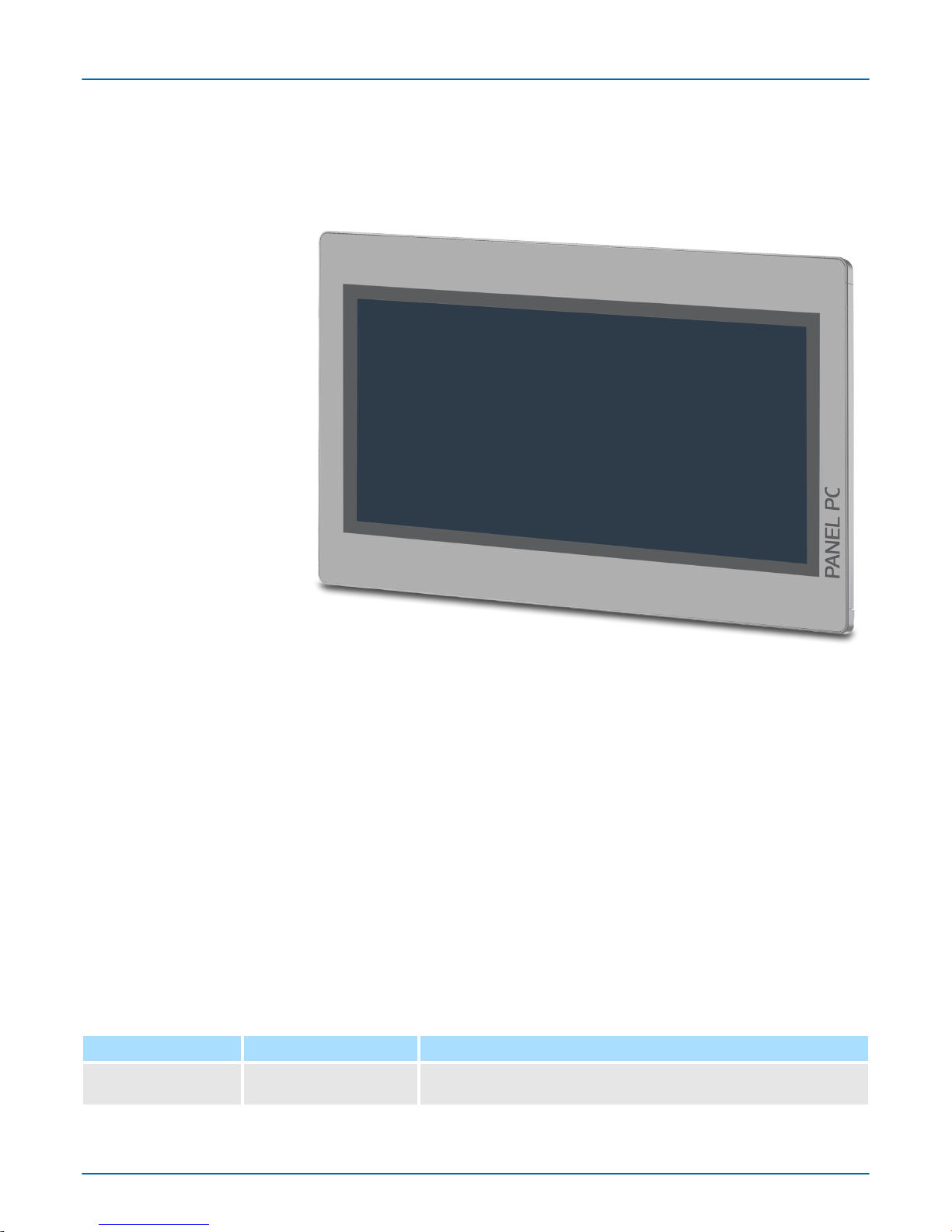
A Panel PC is a combination of industrial PC with state of the art performance
features and a touch panel with ideal display capabilities. The Panel PC is a compact and
modular embedded PC based on WindowsÒ Embedded Compact 7 - WEC7. Besides the
extensive WEC7 functions the Panel PC offers varied communication possibilities.
n WindowsÒ Embedded Compact 7
n Movicon 1
1 CE Standard
n 10.1" 16:10 TFT Panel 262K
n PCAP, multitouch
n Display resolution 1280 x 800
n Processor: Baytrail IntelÒ Celeron J1900, Quad core 2GHz
n Work memory: 2x 204Pin DDR3 SO-DIMM Socket, 2GB DDR3
n User memory: 2GB SATA DOM
n CFast slot
n 2 RS232/RS422/RS485 (switchable by BIOS), 3 USB-A, 2 Ethernet interfaces, VGA
port and Audio out, connector for remote Power switch
n Metal case
n Passive cooling
n Easy mounting via integrated pivoted lever
n Protection class IP66 (frontal)
Order data
Type Order number Description
PPC010 EC 67K-RRJ0-... 10.1'' TFT color, 2x RS232/RS422/RS485, 3x USB-A, 2x Ethernet
RJ45, VGA, Audio out
General
VIPA HMI
Hardware description
Properties
HB160 | PPC | 67K-RRJ0 | en | 18-30 8
Page 9
2.3 Structure
2.3.1
Overview
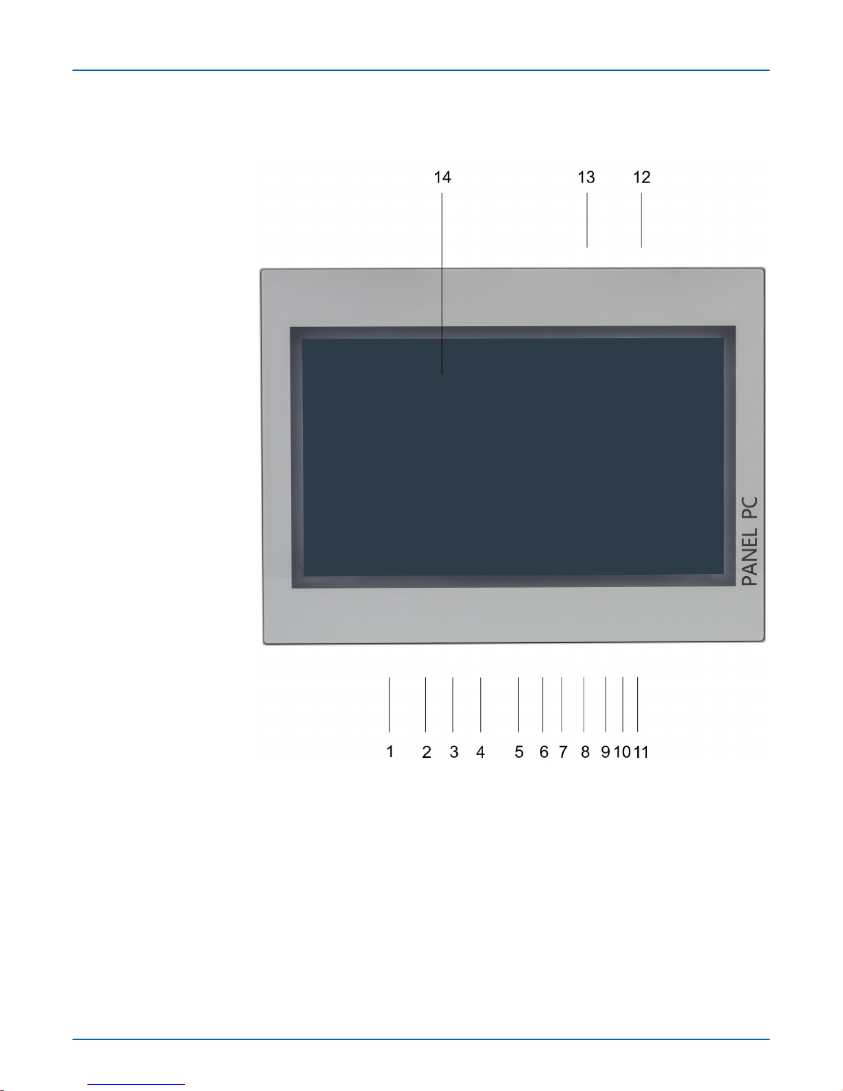
1 Slot for voltage supply (DC 12-30V)
2 VGA interface
3 Reset button
4 RS232/RS422/RS485 interface COM 2
5 RS232/RS422/RS485 interface COM 1
6 USB-A interface USB 3.0
7 2x USB-A interface USB 2.0
8 RJ45 jack for Ethernet communication LAN 2
9 RJ45 jack for Ethernet communication LAN 1
10 2 pin connector for remote Power switch
11 3.5mm Audio Line out
12 Power switch (pushbutton)
13 Slot for CFast storage media
14 Display with touch sensitive area (touch screen)
Front view
VIPA HMI
Hardware description
Structure > Overview
HB160 | PPC | 67K-RRJ0 | en | 18-30 9
Page 10
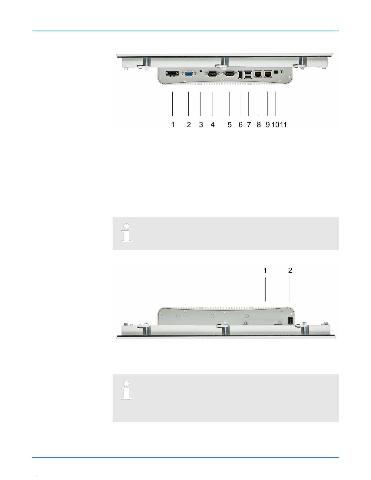
1 Slot for voltage supply (DC 12-30V)
2 VGA interface
3 Reset button
4 RS232/RS422/RS485 interface COM 2
5 RS232/RS422/RS485 interface COM 1
6 USB-A interface USB 3.0
7 2x USB-A interface USB 2.0
8 RJ45 jack for Ethernet communication LAN 2
9 RJ45 jack for Ethernet communication LAN 1
10 2 pin connector for remote Power switch
11 3.5mm Audio Line out
Please make sure that the Panel PC always has to be supplied with
external voltage!
1 Slot for CFast storage media
2 Power switch (pushbutton)
The Panel PC starts automatically when the power supply is switched on.
It may be switched off by the power switch.
But you can change the configuration in the BIOS setup so that the Panel
PC has to be switched on by the power switch.
Ä
‘Restore AC Power
Loss’ page 51
Bottom view
Top view
VIPA HMI
Hardware description
Structure > Overview
HB160 | PPC | 67K-RRJ0 | en | 18-30 10
Page 11
2.3.2 Interfaces
The Panel PC has got an integrated power supply. The power supply has to be provided
with DC 12... 30V
. For this you find an according DC 24V slot at the back. The power
supply is protected against inverse polarity and overcurrent.
VGA SubD HD15 jack to connect a second display.
Power supply
VGA interface
VIPA HMI
Hardware description
Structure > Interfaces
HB160 | PPC | 67K-RRJ0 | en | 18-30 11
Page 12

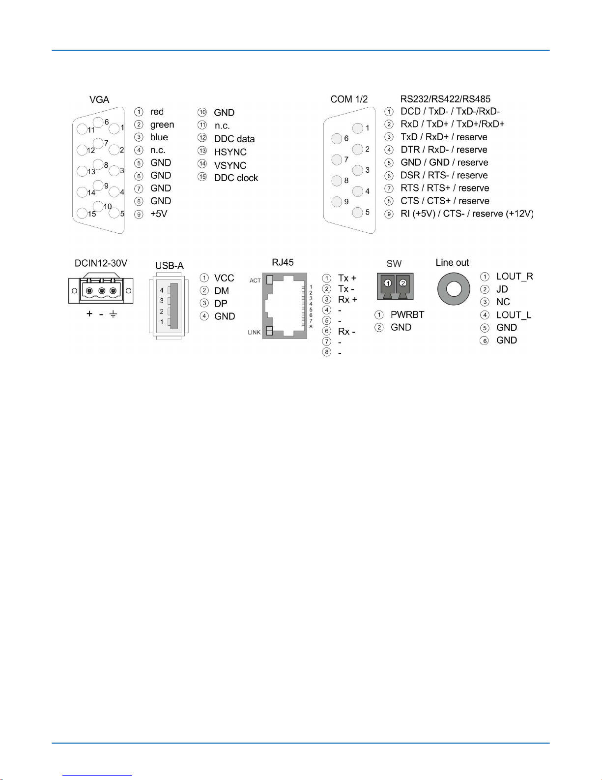
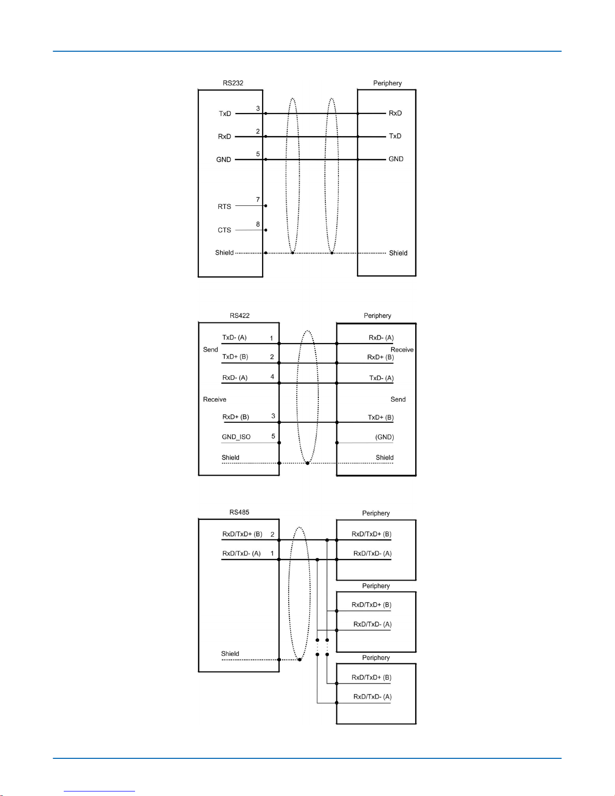
The 9-pin male SubD connector may be switched with BIOS. Here also the termination
resistor of the RS422 and RS485 interface may be activated or deactivated.
Ä
‘Submenu
"Serial Port 2 Configuration"’ page 44
RS232 interface
n Logical conditions as voltage level
n Point-to-point connection with serial full-duplex transfer
n Data transfer up to a distance of 15m
n Data transfer rate up to 1
15.2kbit/s
RS422 interface
n Logical conditions as voltage dif
ference between 2 twisted lines
n Serial bus connection full-duplex four-wire operation
n Line length: 250m at 115.2kbit/s ... 1200m at 19.2kbit/s
n Data transfer rate up to 115.2kbit/s
RS485 interface
n Logical conditions as voltage dif
ference between 2 twisted lines
n Serial bus connection half-duplex two-wire operation
n Line length: 250m at 115.2kbit/s ... 1200m at 19.2kbit/s
n Data transfer rate up to 115.2kbit/s
RS232/RS422/RS485 interface (switchable)
VIPA HMI
Hardware description
Structure > Interfaces
HB160 | PPC | 67K-RRJ0 | en | 18-30 12
Page 13
VIPA HMI
Hardware description
Structure > Interfaces
HB160 | PPC | 67K-RRJ0 | en | 18-30 13
Page 14
The Panel PC has a USB 3.0 and two USB 2.0 interfaces. The fast USB 3.0 interface can
be recognized by the blue connector
. USB 2.0 works half-duplex, the data can only be
transmitted in one direction. USB 3.0 works full-duplex, meaning that data can be transferred simultaneously in both directions. Using the "Host"-USB-A interfaces USB mouse,
keyboard, stick or USB hard discs can be connected.
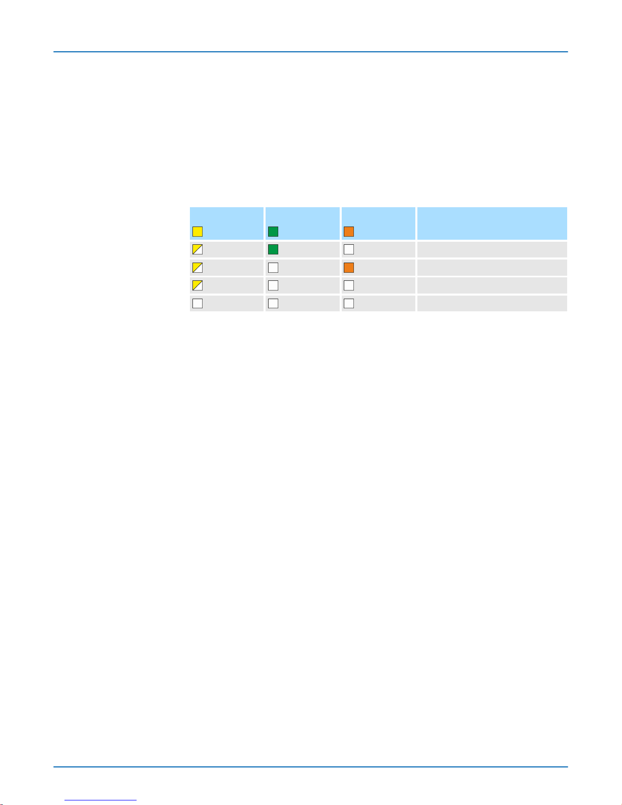
The two RJ45 jacks provide the interface to the twisted pair cable, required for Ethernet.
LEDs
Activity
yellow
Link
green
Link
orange
Description
blinks
1000Mbit/s link
blinks
100Mbit/s link
blinks
10Mbit/s link or no link
not active
At this connection, you can connect an additional pushbutton as a remote Power switch
to switch the PPC on or of
f from any location.
Ä
further information page 10
3.5 mm stereo jack to connect an active speaker system or an earphone.
"Host"-USB-A
Ethernet connection
Remote Power switch
connection
(SW)
Line out
VIPA HMI
Hardware description
Structure > Interfaces
HB160 | PPC | 67K-RRJ0 | en | 18-30 14
Page 15
2.3.3 Memory management
n 2GB work memory
n 2GB SA
TA DOM user memory
n USB storage media using "Host"-USB-A interface
n Slot for CFast memory card
The Panel PC has a work memory with a size of 2GB. The work memory is not buffered
and is deleted after shut down.
As internal permanent storage medium the Panel PC has a 2GB flash module
(1600Mbyte for user data). After the start of WindowsÒ this memory is listed as Flashdisk
under My Device.
The Panel PC has got three USB-A interfaces (1x USB 3.0 and 2x USB 2.0). The connection of USB sticks and USB drives are supported by the Panel PC.
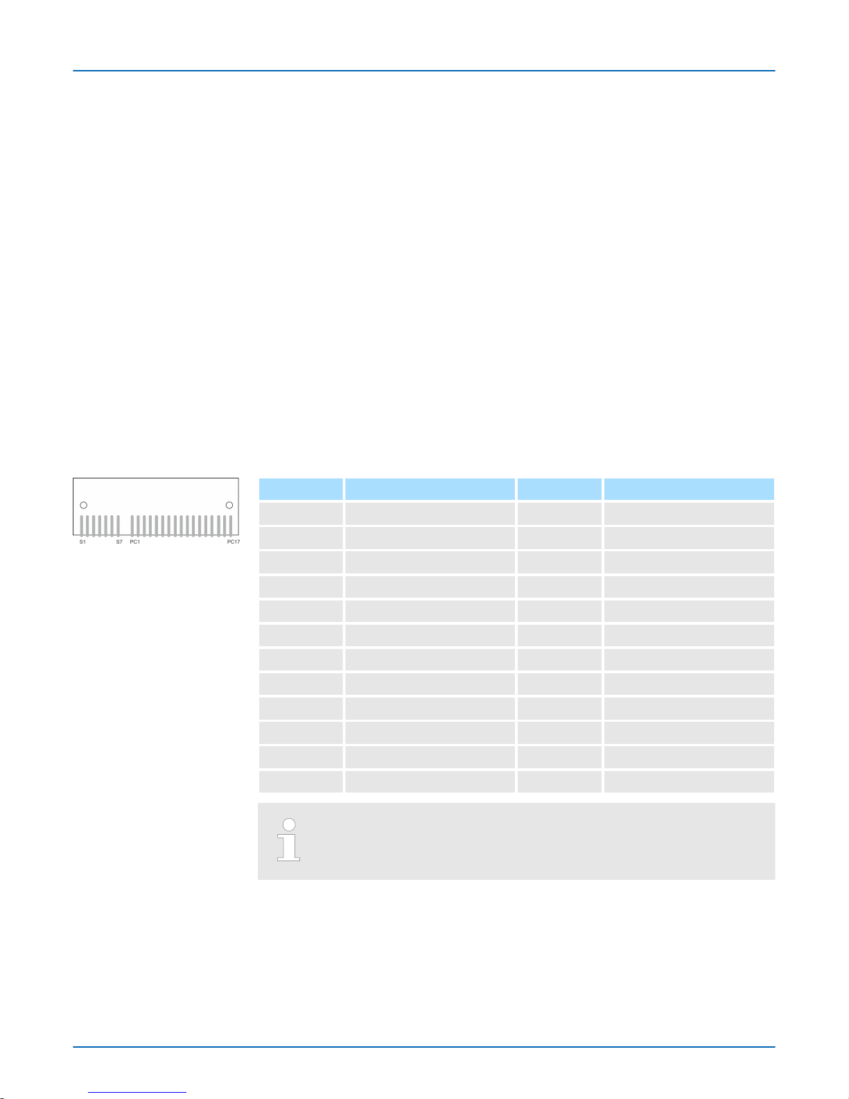
At the back of the Panel PC there is a card slot for a memory card. At this slot you can
plug storage modules of the type CFast 2.0 - 600 MB/s (6GBit/s) - SA
TA protocol - not
hot-swap compatible.
Pin Assignment Pin Assignment
S1 GND PC6 n.c.
S2 SATA_TX1+ PC7 GND
S3 SATA_TX1- PC8 CFAST_LED1_C
S4 GND PC9 CFAST_LED2_C
S5 SATA_RX1+ PC10 n.c.
S6 SATA_RX1- PC11 n.c.
S7 GND PC12 n.c.
PC1 CFAST_CDI PC13 VCC3
PC2 GND PC14 VCC3
PC3 n.c. PC15 GND
PC4 n.c. PC16 GND
PC5 n.c. PC17 CFAST_CDO
Prior to removing the CFast card, make sure the unit's power is off and
disconnected from the power supply
.
Overview
Work memory
User memory
USB storage media
Slot for CFast
VIPA HMI
Hardware description
Structure > Memory management
HB160 | PPC | 67K-RRJ0 | en | 18-30 15
Page 16
2.4 Dimensions
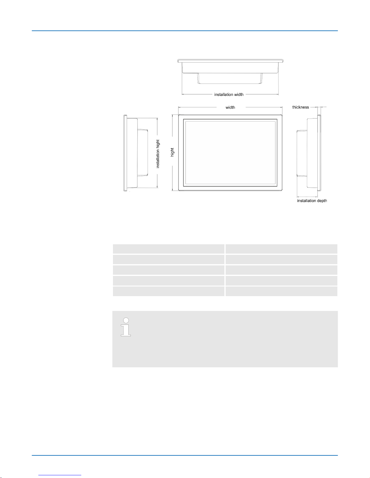
For the installation of the Panel PC in control cabinets and desks the following dimensions are necessary:
Front panel thickness 3 ... 12mm
Installation cutting (W x H) 297 x 212mm
Front panel (W x H x T) 308 x 223 x 6.70mm
Rear panel (W x H x D) 292 x 207 x 54.20mm
Installation depth 54.20mm
The degrees of protection are only guaranteed when the following is
observed:
– The material thickness of the installation cut-out is
3 ... 12mm
– The deviation from the plane for the panel cut-out is £ 0.5mm
– Permissible surface roughness in the area of the seal:
£
120µm (fric-
tion coefficient 120)
Installation dimensions
10.1" - 67K-RRJ0-...
VIPA HMI
Hardware description
Dimensions
HB160 | PPC | 67K-RRJ0 | en | 18-30 16
Page 17
2.5 General data
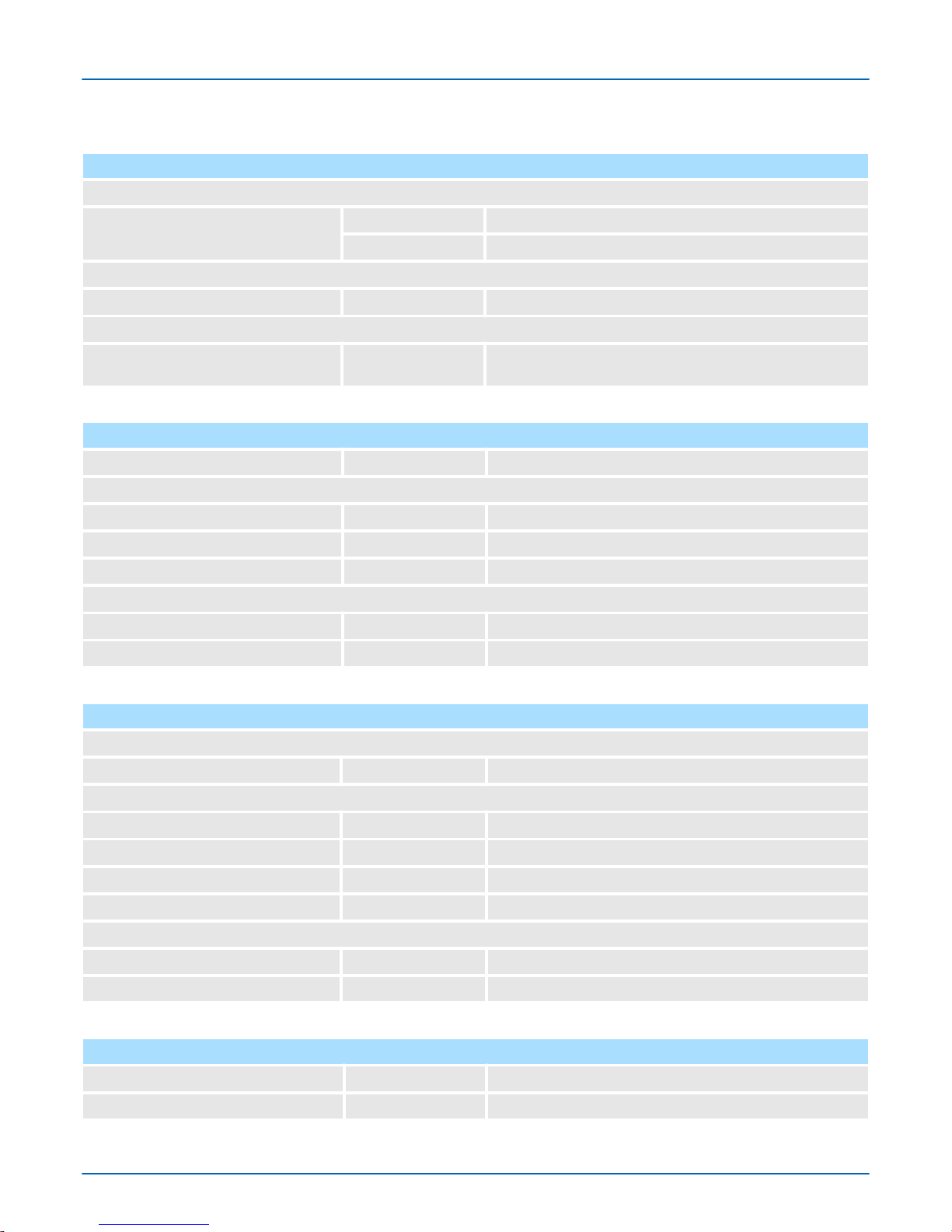
Conformity and approval
Conformity
CE 2014/35/EU Low-voltage directive
2014/30/EU EMC directive
Approval
UL Refer to Technical Data
others
RoHS 2011/65/EU Restriction of the use of certain hazardous substances in
electrical and electronic equipment
Protection of persons and device protection
Type of protection - IP20
Electrical isolation
to the field bus - electrically isolated
to the process level - electrically isolated
Insulation resistance -
Insulation voltage to reference earth
Inputs / outputs - AC / DC 50V, test voltage AC 500V
Protective measures - against short circuit
Environmental conditions to EN 61131-2
Climatic
Storage / transport EN 60068-2-14 -20…+75°C
Operation
Horizontal installation EN 61131-2 -10…+60°C
Vertical installation EN 61131-2 -10…+60°C
Air humidity EN 60068-2-30 RH1 (without condensation, rel. humidity 10…95%)
Pollution EN 61131-2 Degree of pollution 2
Mechanical
Oscillation EN 60068-2-6 1g, 9Hz ... 150Hz
Shock EN 60068-2-27 15g, 11ms
Mounting conditions
Mounting place - In the control cabinet
Mounting position - Horizontal and vertical
VIPA HMI
Hardware description
General data
HB160 | PPC | 67K-RRJ0 | en | 18-30 17
Page 18

EMC Standard Comment
Emitted interference EN 61000-6-4 Class A (Industrial area)
Noise immunity
zone B
EN 61000-6-2 Industrial area
EN 61000-4-2
ESD
8kV at air discharge (degree of severity 3),
4kV at contact discharge (degree of severity 2)
EN 61000-4-3 HF field immunity (casing)
80MHz … 1000MHz, 10V/m, 80% AM (1kHz)
1.4GHz ... 2.0GHz, 3V/m, 80% AM (1kHz)
2GHz ... 2.7GHz, 1V/m, 80% AM (1kHz)
EN 61000-4-6 HF conducted
150kHz … 80MHz, 10V
, 80% AM (1kHz)
EN 61000-4-4 Burst, degree of severity 3
EN 61000-4-5 Surge, degree of severity 3 *
*) Due to the high-energetic single pulses with Surge an appropriate external protective circuit with lightning protection elements like conductors for lightning and overvoltage is
necessary
.
VIPA HMI
Hardware description
General data
HB160 | PPC | 67K-RRJ0 | en | 18-30 18
Page 19
2.6 Technical data
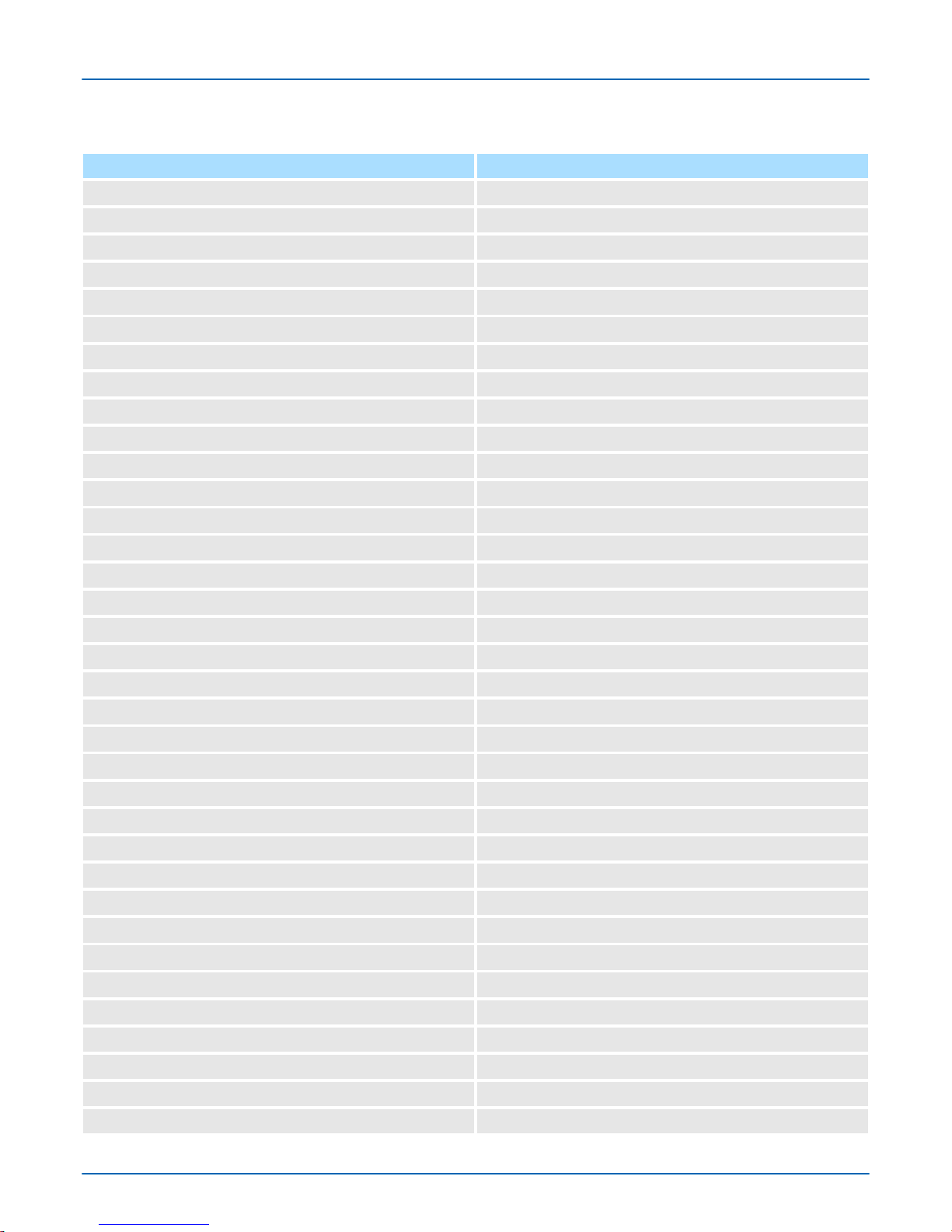
Order no. 67K-RRJ0-EB
Type Panel PC PPC010 CE
Display
Display size (diagonal) 10.1 "
Display size (width) 217 mm
Display size (height) 136 mm
Resolution 800 x 1280 / 1280 x 800
Aspect ratio 16:10
Type of display TFT color (262K colors)
MTBF Backlights (25°C) 50000 h
System properties
Processor Intel Celeron Quad core 2 GHz
Operating system Windows embedded Compact 7
User software Movicon 11 CE Standard
Work memory 2 GB
User memory 2 GB
Available memory (user data) 1600 MB
SD/MMC Slot -
CF Card Slot Typ II -
CFast Slot
ü
Time
Real-time clock buffered
ü
Clock buffered period (min.) 4 y
Type of buffering lithium battery
Load time for 50% buffering period -
Load time for 100% buffering period -
Accuracy (max. deviation per day) 10 s
Operating controls
Touchscreen PCAP
Touch function Dual Touch
Keyboard external via USB
Mouse external via USB
Interfaces
MPI, PROFIBUS-DP -
MPI, PROFIBUS-DP connector -
Serial, COM1 RS232 / RS422 / RS485
VIPA HMI
Hardware description
Technical data
HB160 | PPC | 67K-RRJ0 | en | 18-30 19
Page 20

Order no. 67K-RRJ0-EB
COM1 connector Sub-D, 9-pin, male
Serial, COM2 RS232 / RS422 / RS485
COM2 connector Sub-D, 9-pin, male
Number of USB-A interfaces 3
USB-A connector USB-A (host)
Number of USB-B interfaces -
USB-B connector -
Number of ethernet interfaces 2
Ethernet Ethernet 10/100/1000 MBit
Ethernet connector 2 x RJ45
Integrated ethernet switch -
Video connectors VGA SubD HD15
Audio connections Line out, stereo jack 3.5 mm
Technical data power supply
Power supply (rated value) DC 24 V
Power supply (permitted range) DC 20.4...28.8 V
Reverse polarity protection
ü
Current consumption (no-load operation) 1.2 A
Current consumption (rated value) 1.3 A
Inrush current 1.3 A
I²t 0.35 A²s
Power loss 32 W
Status information, alarms, diagnostics
Supply voltage display none
Mechanical data
Housing / Protection class
Material coated aluminium steel plate
Mounting via integrated pivoted lever
Protection class IP front side IP 66
Protection class IP back side IP 20
Protection class NEMA front side -
Protection class NEMA back side -
Dimensions
Front panel 308 mm x 223 mm x 6.7 mm
Rear panel 292 mm x 207 mm x 54.2 mm
Installation cut-out
VIPA HMI
Hardware description
Technical data
HB160 | PPC | 67K-RRJ0 | en | 18-30 20
Page 21

Order no. 67K-RRJ0-EB
Width 297 mm
Height 212 mm
Minimum 3 mm
Maximum front panel thickness 12 mm
Net weight 4 kg
Weight including accessories -
Gross weight -
Environmental conditions
Operating temperature -10 °C to 60 °C
Storage temperature -20 °C to 75 °C
Certifications
UL certification yes
KC certification -
VIPA HMI
Hardware description
Technical data
HB160 | PPC | 67K-RRJ0 | en | 18-30 21
Page 22
3 Deployment Panel PC
3.1 Installation
The Panel PC is suitable for the installation in operating tables and control cabinet fronts.
The installation happens via the back. The Panel PC is provided with a fixing technique
with not losable screws that allows an easy connection with a crosstip screwdriver. A fast
and easy device change is possible. It is also possible to install the Panel PC in a VESA
holder (VESA 75/100).
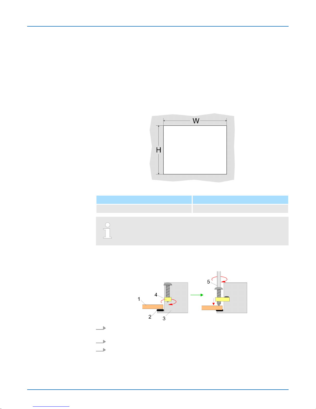
For the installation into a operating tableau and control cabinet fronts, the Panel PC
requires the following front panel cutting:
Panel PC W x H in mm
67K-RRJ0-... 297 x 212mm
The material thickness of the installation cut-out is 3 ... 12mm.
For the installation of the panel pivoted lever are integrated. For the installation, a crosstip
screwdriver is required.
1. Push the Panel PC [3] from the front side into the front panel cutting [1] until it
touches the panel with the seal [2].
2. Rotate the pivoted lever 90 degrees to the outside [4].
3. Screw the screws with the crosstip screwdriver [5].
Overview
Installation cutting
Installation
VIPA HMI
Deployment Panel PC
Installation
HB160 | PPC | 67K-RRJ0 | en | 18-30 22
Page 23
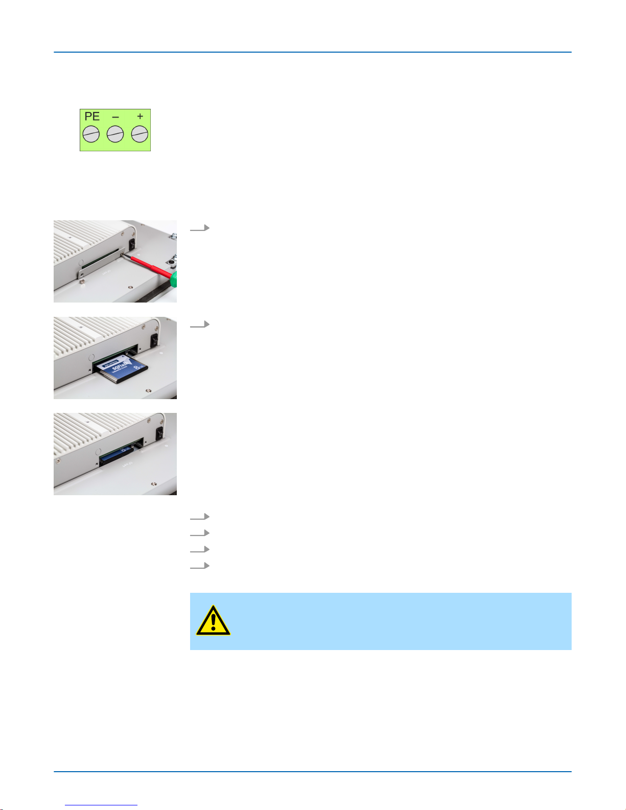
For the cabling of the power supply DC 12-30V a green plug is used. The connector is a
plug with screw contacts. The plug has the following assignment:
+ DC 24V
- DC 0V
PE Protective earth
3.2 Installation of the CFast card
The CFast card slot is located on the rear top side of the Panel PC. It is closed with a
cover plate.
1. Remove the cover plate of the slot by removing the screws and pulling the plate.
2. With the label facing up, insert the CFast card until it is completely seated in the slot
and reinstall the cover plate.
ð
After installation the CFast card is automatically recognized.
1. Remove the screws.
2. Pull the holding plate from the card slot.
3. Push the CFast card to remove the card.
4. Reinstall the cover plate.
CAUTION!
Prior to removing the CFast card, make sure the unit's power is of
f and
disconnected from the power supply.
Connect power supply
Installation
Demounting
VIPA HMI
Deployment Panel PC
Installation of the CFast card
HB160 | PPC | 67K-RRJ0 | en | 18-30 23
Page 24

3.3 Commissioning
CAUTION!
– Before commissioning the device must be brought to room tempera-
ture.
–
At condensation the device must be absolutely dry before connected
to power.
– To avoid overheat during operation the device must not be laid open
to direct sun light.
– After opening the control cabinet or desk, there are parts with pos-
sible dangerous voltage available.
– For all signal connections only screened cables are permitted.
– Signal cables must not be let within the same cable shaft as high
voltage cables.
3.3.1 Firmware update
T
o execute the firmware update an external keyboard and an USB stick (memory size
4GB) is necessary. The new image file for your Panel PC should be on the USB stick.
You will find the file and a detailed description of the firmware update on
www.vipa.com
under "Service / Support" in the download area.
In the "VIP
A Startup Manager", run the Firmware update of your Panel PCs via the [Info/
Update] button.
Firmware update without
Startup Manager
Firmware update with
Startup Manager
VIPA HMI
Deployment Panel PC
Commissioning > Firmware update
HB160 | PPC | 67K-RRJ0 | en | 18-30 24
Page 25
3.3.2 VIPA Startup-Manager
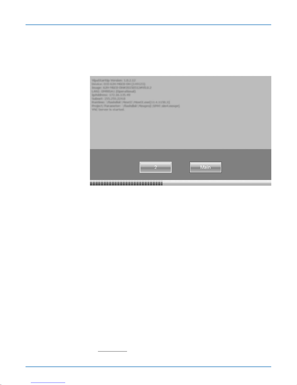
As soon as the Panel PC is provided by power supply
, the VIPA Startup-Manager will be
loaded. At the first startup of the VIPA Startup-Manager the following start screen
appears.
n There is a button on the initial screen with a counter
, which counts backwards. If you
click on this button within this time, the project will start. If the time expires, the project
will start automatically. With the button ‘Main’ you get to the ‘selection menu’ .
n A delay time of 5 seconds is default. In the selection menu under "Autostart" you can
adjust this time.
There are following buttons in the selection menu:
n Settings
n Info/Update
n Autostart
n Backup
n Exit
n Back
In [Settings] under Change Settings you can set a password for the Startup-Manager
.
The password will be requested when interrupting the start countdown. By default, no
password is defined. In [Settings] the system settings can be set exactly like via Windows
‘Start è Settings è Control Panel’.
n T
o execute the firmware update press the button [Info/Update]. After clicking [Info/
Update] the current image is displayed under ‘Image Version’ with panel name, creation date and version number. With [Create Screenshot] you can make a screen shot
of the panel information and select a destination for its storage.
n To execute the firmware update an external keyboard and an USB stick (memory size
4 GB) is necessary. The new image file for your Panel PC should be on the USB
stick. You will find the file and a detailed description of the firmware update on
www.vipa.com under "Service / Support" in the download area.
Start screen
Selection menu
Settings
Info/Update (firmware)
VIPA HMI
Deployment Panel PC
Commissioning > VIPA Startup-Manager
HB160 | PPC | 67K-RRJ0 | en | 18-30 25
Page 26
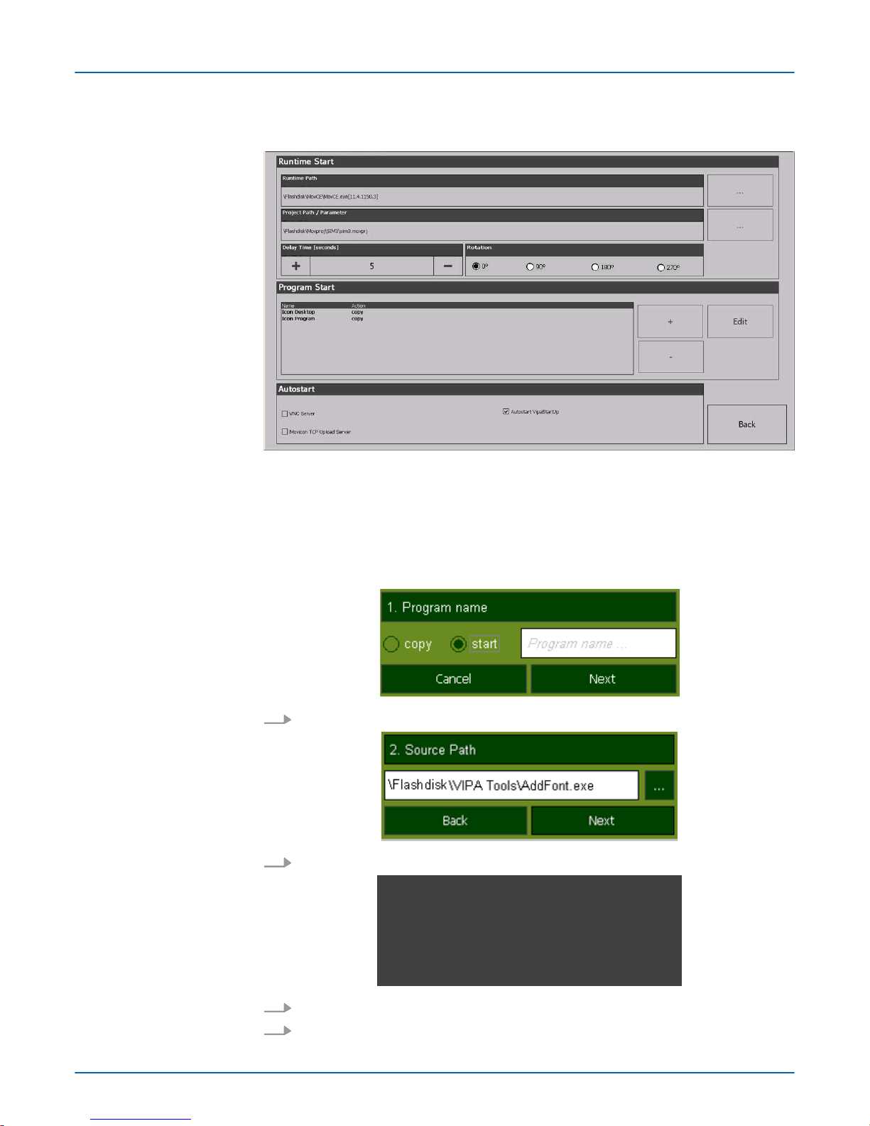
With [Autostart] you define which runtime and which project will be started automatically
together with the panel startup.
n With [...] at ‘ Runtime path’ res. ‘Project path’ all existing runtimes res. projects on the
panel and the storage media will be listed.
n Under ‘Delay T
ime’ you can adjust a delay time > 0 by using the buttons [+] and [-]. 5
seconds are default.
n Via "Program start" with [+] you can add programmes, which have to start automati-
cally.
n Via "Rotation" the orientation of the panel can be changed.
1. Select "start" and assign a name for the program.
2. Upload your program with [...].
3. You can optionally set parameters.
4. Exit with [Finish].
Autostart
VIPA HMI
Deployment Panel PC
Commissioning > VIPA Startup-Manager
HB160 | PPC | 67K-RRJ0 | en | 18-30 26
Page 27

n With ‘Copy’ [...] files can be copied on the panel from a source path to a destination
path.
n With ‘Autostart’ you can select the automatic startup of the VNC Server
, the MoviconTCP upload server und the Startup-Manager. With [back] you can return to the select
menu.
By default, the configuration of the Startup-Manager, the registry settings for the backlight, the local settings and the LAN settings will be saved by [Backup] in ‘Flashdisk
è Backup’. The name of the backup file is "backup.bkv". Which settings will be saved
and the storage location are defined in the file "ToDoList.xml" under ‘Flashdisk
è VipaStartup’. These can be adjusted accordingly.
The Startup-Manager will be closed by [Exit] and the system returns to the Windows
Ò
screen.
With [Back] you get back to the start screen of the Startup-Manager.
Backup
Exit
Back
VIPA HMI
Deployment Panel PC
Commissioning > VIPA Startup-Manager
HB160 | PPC | 67K-RRJ0 | en | 18-30 27
Page 28
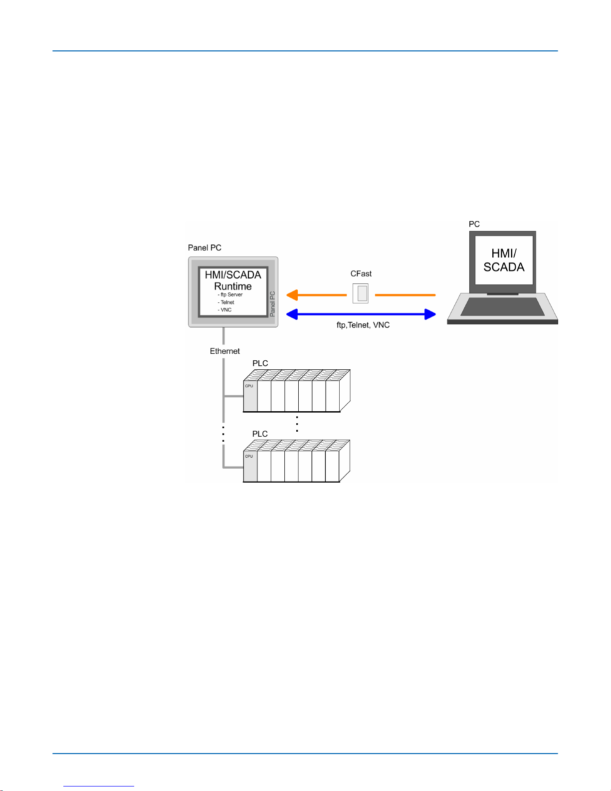
3.4 Connection to a PLC system
n For the inclusion into your PLC system several HMI/SCADA project-engineering plat-
forms are at your disposal that has to be installed on an external PC. Here you can
create your project, where appropriate simulate it and transfer it to the Panel PC via a
connection that you’ve entered before. V
ia the on the Panel PC pre-installed runtime
version of the HMI/SCADA project engineering platforms your project is run able.
n By using the according communication driver, the Panel PC supports connecting
options to the PLC via Ethernet.
n During operation your operating device communicates with the according PLC and
reacts to the application courses in the PLC according to the configured processes.
Via dialogues configured before, process values can be monitored graphically, altered
and evaluated.
Overview
VIPA HMI
Deployment Panel PC
Connection to a PLC system
HB160 | PPC | 67K-RRJ0 | en | 18-30 28
Page 29

3.5 Operating system Windows Embedded Compact 7
3.5.1
General
WindowsÒ Embedded Compact 7 - WEC7 is the next generation of Windows CE operating systems designed for innovative and small-footprint devices.
n File viewer for W
ord, Excel, PowerPoint and PDF
n ftp, Telnet and VNC server
n RDP (Remote Desktop Protocol)
n Internet Explorer
n Registry Editor
n WordPad
n USB keyboard driver
n VIPA Startup-Manager
Please regard that for the deployment of WEC7 a thorough knowledge of operating WindowsÒ are assumed. Here are only shown the dif
ferences to a "standard" Windows
Ò
operating system.
You’re operating the Panel by means of a pencil for capacitive touch screen res. with the
finger
. The following types of entry are differentiated:
n Double click
A double click has to be executed like mouse operation by touching the area on the
screen twice. A double click on an object opens res. executes this.
n Drag
By tapping on an object and then dragging you can move the object on the screen. If
no object is selected, a frame is created by the dragging that selects the touched
objects.
The windows can be moved via the head bar. Here you can also find the [OK] button to
confirm entries and the [X] button for exiting the dialog.
Y
ou can not exit WEC7. By switching the power supply off and on again you can restart
WEC7. Before a reboot you should always save your data res. close all running applications to avoid data loss.
For manual storage please use the "Store" tool via ‘Start è Programs è Tools
è System Tools’.
To reboot the operating system (soft reset) please use the "Soft-Reset" tool via ‘Start
è Programs è Tools è System Tools’.
Features
Differences to the
standard W
indowsÒ opera-
tion
Pen entry
Navigation within the
dialog window
Exit WEC7 (shut down)
Manual storage
Soft reset
VIPA HMI
Deployment Panel PC
Operating system Windows Embedded Compact 7 > General
HB160 | PPC | 67K-RRJ0 | en | 18-30 29
Page 30
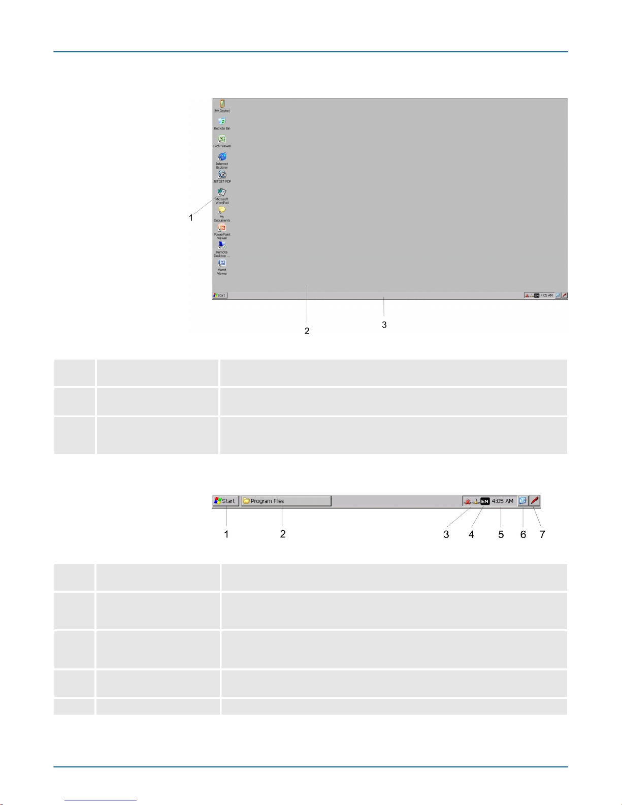
3.5.2 Structure
1 Icon Via icons on the desktop you gain direct access to the application related to the
icon.
2 Desktop
The desktop is the screen that is shown after login to Windows Ò. It contains e.g.
links to the mostly used applications res. system components.
3 Task bar The task bar is part of the desktop. When opening an application, a document or
a window
, every running object is displayed as button on the task bar. Via this
buttons you can easily change between the open windows.
Basically the taskbar has the following structure:
1 Start button This button offers you access to all components of your Panel PC such as appli-
cations, system settings, file browser etc.
2 Open applications For every open application a button can be found in the task bar. There is no
button for minimizing. The switch between the applications is performed via this
buttons.
3 Network connection As soon as your Panel PC is connected via Ethernet you can see here the
Ethernet address. If there is no connection via Ethernet, the symbol is displayed
crossed out.
4 Keyboard layout If you’ve connected a keyboard you can choose the requested language layout
via this button.
5 Time This area shows the time that you can change via double click.
Task bar
VIPA HMI
Deployment Panel PC
Operating system Windows Embedded Compact 7 > Structure
HB160 | PPC | 67K-RRJ0 | en | 18-30 30
Page 31
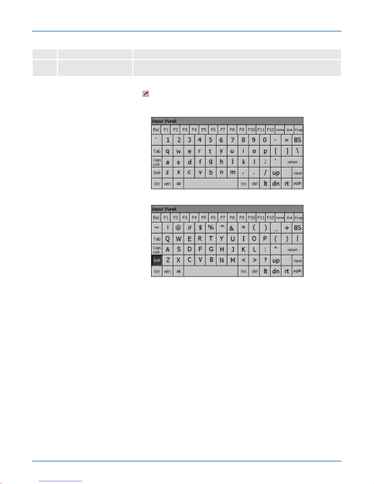
6 Show desktop All windows are minimized and the desktop is shown.
7 Software keyboard This button displays a keyboard at the screen. "Hide Input Panel" hides the key-
board again.
The button allows you to select one of the available software keyboards. At the
moment the following standard keyboards are implemented:
At pushed Shift key:
Home Position 1
End End
BS Backspace
up
á
dn
â
lt
ß
rt
à
pgup
Pageá
pgdn
Page â
ins Insert
del Delete
Tab Tabulator
Shift
Caps/Lock
The software keyboard allows you to enter key entries without connecting an external
keyboard. As soon as an entry is required the software keyboard is automatically shown.
Hide Input Panel hides the keyboard again.
As many components of the Control Panel conform with the System Control of WindowsÒ, most of the description is not necessary. The description of the control panel components relevant for operating the Panel PC can be found in the following:
Software keyboard
Large Keyboard
Hide keyboard
System setting (Control
Panel)
VIPA HMI
Deployment Panel PC
Operating system Windows Embedded Compact 7 > Structure
HB160 | PPC | 67K-RRJ0 | en | 18-30 31
Page 32

n Set Display
V
ia ‘Start è Settings è Control Panel è Display’ the dialog windows for the display
properties opens. Here you can change the settings for the monitor options.
n Set Ethernet Parameters
The dialog field for pre-setting an Ethernet address can be found in ‘Start è Settings
è Network and Dial-up Connections’. The default setting is address assignment via
DHCP.
Please consider with the manual assignment of IP addresses that these
are not identical for both interfaces.
n System Properties (System)
V
ia ‘Start è Settings è Control Panel è System’ you receive information about the
version of the current WindowsÒ operating system, the memory load and sharing
(alterations here are not accepted into the registry) and the copyright. The register
‘Device Name’ allows you to change the device name that is shown during Ethernet
communication for instance.
3.6 Integrated server
3.6.1
General
The Panel PC has several integrated server that enable a remote maintenance within a
network. Some servers only allow access by means of entering User name and Pass-
word. The following login data are used standardly:
User name: wince
Password: vipatp
Per default the following server are integrated:
n ftp server (activated)
n T
elnet (activated)
n VNC (not activated)
Phrases that are used in the description of the server:
A client is an application that uses the service of a server within a network. For example,
a web browser is a client because at every call of a website it sends a request to a web
server and receives an answer
.
A server is an application that waits for the contact request of a client application and
exchanges messages with it after contact start. This communication type is called ClientServer communication.
Computer within a network where at least one server is running.
Data transfer Server ® Client
Login data
Overview
Phrases
Client
Server
Host
Download
VIPA HMI
Deployment Panel PC
Integrated server > General
HB160 | PPC | 67K-RRJ0 | en | 18-30 32
Page 33
Data transfer Client ® Server
3.6.2
ftp server
By means of a ftp server data between client and server can be exchanged. Here you
can copy, delete or create files and directories.
Depending on the ftp client your PC must have the following conditions for a ftp connection. If there are still problems with the ftp access please ask your system administrator.
Internet Explorer
n ftp access possible with version 5.5 or higher
n activate directory view for ftp sites
For the adjustment choose in the Internet Explorer ‘Options è Internet options’, register
"extended" in the area "Browsing” and set the following settings:
1. activate: "activate directory view for ftp sites"
2. Restart the Internet Explorer
.
ð
The settings are saved.
Below is explained, how to establish of a ftp connection between a WindowsÒ based PC
with Windows Explorer as ftp client and your Panel PC.
1. Connect your Panel PC with the network where your PC is a member via an
Ethernet cable.
2. Switch on your Panel PC.
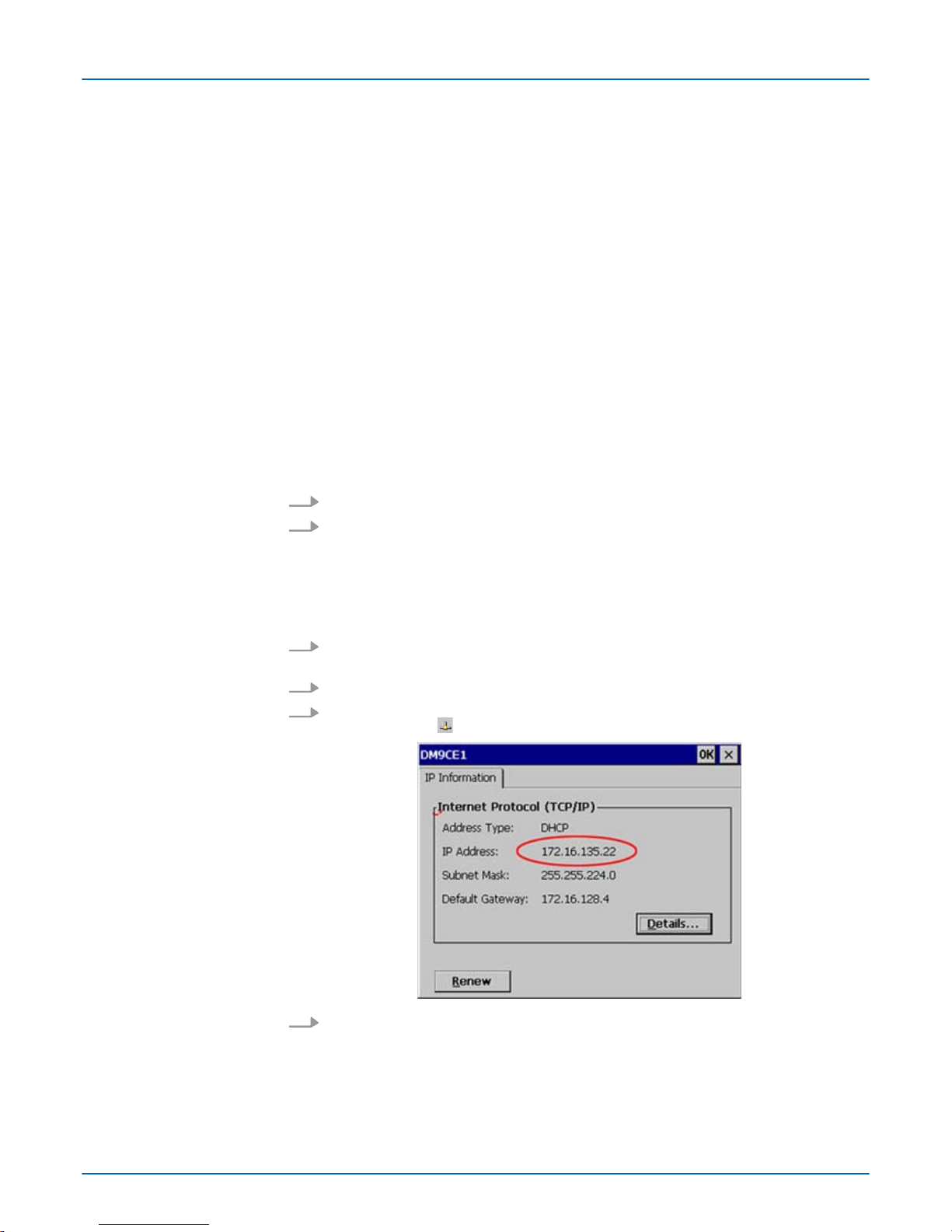
3. As soon as your Panel PC is connected via Ethernet, you can monitor the IP
address data via in the taskbar.
4. After you’ve confirmed the pre-settings, start your ftp client (e.g. Windows Explorer)
and enter the following text into the "address bar":
ftp://wince:vipatp@IP-Adresse
ð
In the appearing explorer window you can execute the requested file operations.
Upload
Conditions for ftp access
Establishing a ftp connection
VIPA HMI
Deployment Panel PC
Integrated server > ftp server
HB160 | PPC | 67K-RRJ0 | en | 18-30 33
Page 34
3.6.3 Telnet server
T
elnet is a text based client-server protocol on TCP level. Using of a Telnet client like e.g.
the "MS-DOS console" in your WindowsÒ operating system you may execute text based
all file remote functions at your Panel PC like copy, delete and create files and directories.
You can also start applications. Terminating an application is not possible.
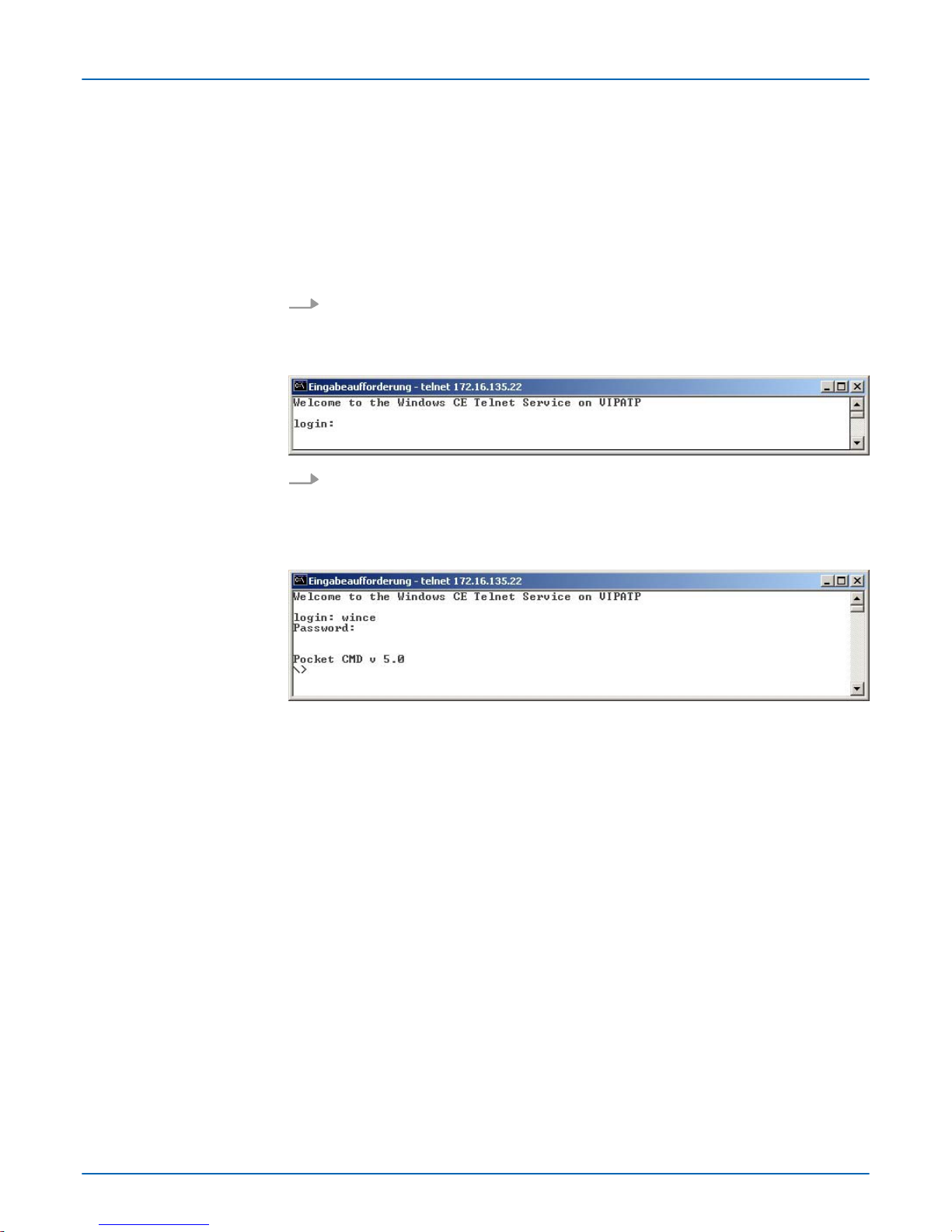
The establishing of a Telnet connection is password protected and has the following
approach:
1. Start a T
elnet client like for example "MS-DOS console" at your PC and enter the
following into the address bar: telnet IP address.
ð
When the connection is established, the Panel PC asks for the user name and
the password.
2. Enter the following:
Login: wince
Password:
vipatp (entry is hidden)
ð
After entering valid user data a command line for entries appears:
By entering Exit res. closing the window you can terminate the T
elnet connection at any
time.
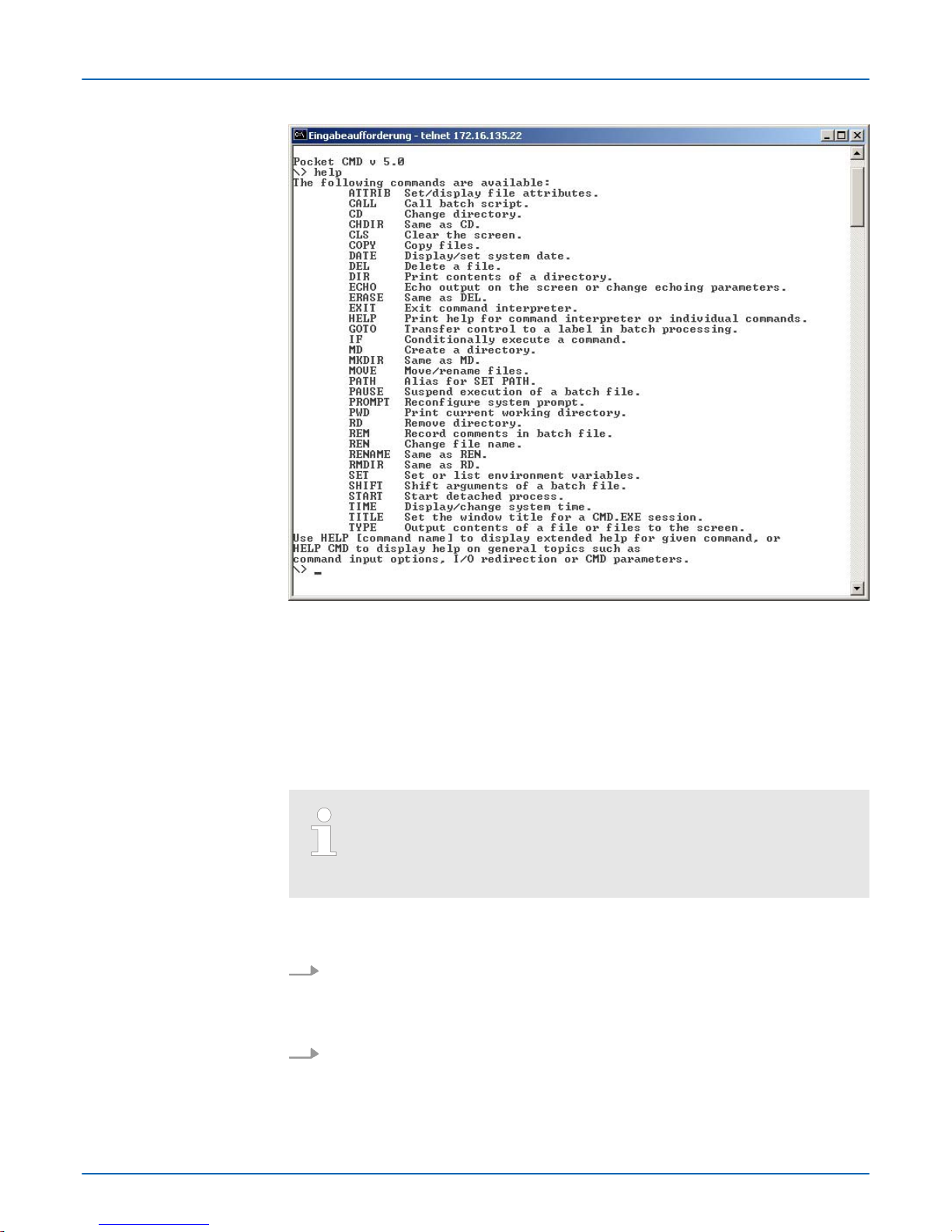
After establishment of a Telnet connection the Panel PC provides you with commands. A
list of possible commands with a short description is available via the command help. By
beginning with "help" before a command you receive help to this command.
Establishing a Telnet connection
Commands
VIPA HMI
Deployment Panel PC
Integrated server > Telnet server
HB160 | PPC | 67K-RRJ0 | en | 18-30 34
Page 35
3.6.4 VNC server
The Panel PC has an integrated VNC server (virtual network control) that allows the total
control of the Panel PC with a PC via network. For this, a window displays the current
Panel PC content for remote control. Operation is performed via PC keyboard and
mouse. Condition for the VNC communication is, that the VNC server is started on the
Panel PC and a VNC client on the PC. Y
ou can download a VNC client as freeware from
internet.
Because you can deactivate all safety attitudes with the VNC server, you
should use these exclusively for start-up! For this reason the VNC server
is on delivery deactivated.
Due to software reasons VIP
A does not support the VNC server function!
The VNC connection establishment has the following approach:
1.
Start the VNC server via ‘Start è Programs è T
ools è winvnc’ or activate the
VNC server in the Startup-Manager under "Autostart".
ð
To show the server has been started, the symbol Efon vnc appears in the task
bar.
2. Now start the VNC client vncviewer
.exe on your PC.
Establishing a VNC connection
VIPA HMI
Deployment Panel PC
Integrated server > VNC server
HB160 | PPC | 67K-RRJ0 | en | 18-30 35
Page 36
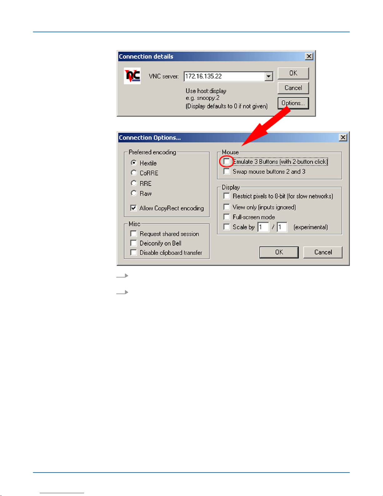
3. Click on [Options] and deactivate the field "Emulate 3 Buttons..." like shown at
Mouse.
4. Enter the IP address of the Panel PC at VNC server. Click on [OK] and enter the
password vipatp. You can change the password over the configuration file, for this
execute vncconfig.exe. Now a VNC connection is established and the screen content of the Panel PC is monitored within a window.
Closing the VNC window terminates the VNC connection, the server keeps running.
VIPA HMI
Deployment Panel PC
Integrated server > VNC server
HB160 | PPC | 67K-RRJ0 | en | 18-30 36
Page 37

3.7 Access to the network resources
The Panel PC allows you to access shared resources in a Microsoft network like drives
and printer
. Here you may assign existing public directories or printer in the network to
local directories or printer in the Panel PC.
Condition for this is that you are logged in to the network with your user name and password. The assignment of a network resource is performed in the Panel PC via the command console "Command Prompt". Start the command console with ‘START
è Programs è Command Prompt’.
The access to the network resource is performed with the commands Net view and Net
use.
Shared resources of a network PC can be listed by the command: \> net view PC-
Name
For example net view testserver lists all shared resources of the network PC "test
server". To test the physical connection a PING to the IP address of the network PC may
be executed if there are problems while contacting the network PC.
The connection of a local name at the Panel PC with a shared drive of the network PC
happens with the following approach:
1. Enter the following in the command prompt: \> net use local_name \
\network drive /user:User name
2. Enter user name, password and where app. user group.
After successful login the following message appears: ‘Successfully mapped to network
name’ .
The connected network drive is then available on the Panel PC with the local name via
My Device at Network.
Local_Name: data, network drive: testserver\archive, Username: guest
Input: \> net use data \\testserver\archiv /user:guest. The connected
network drive is then available via \network\data at the Panel PC.
The listing command for all network connections of your Panel PC is \> net use.
Y
ou may terminate already assigned network resources via:
\> net use local_name /d
Example: \> net use data /d deletes the network connection to the drive "archive" of
"test server".
Overview
List released resources
Connect net drive
Example:
List network connections
Terminate network connections
VIPA HMI
Deployment Panel PC
Access to the network resources
HB160 | PPC | 67K-RRJ0 | en | 18-30 37
Page 38

4 BIOS setup
4.1 Overview
n In this chapter you will find information, required for calling the BIOS setup and the
possible settings.
n The BIOS (Basic Input and Output System) setup program is a menu driven utility that
enables you to make changes to the system configuration and tailor your system to
suit your individual work needs. It is a ROM-based configuration utility that displays
the system’
s configuration status and provides you with a tool to set system parame-
ters.
n These parameters are stored in non-volatile battery-backed-up CMOS RAM that
saves this information even when the power is turned off. When the system is turned
back on, the system is configured with the values found in CMOS.
n With easy-to-use pull down menus, you can configure such items as:
– Hard drives, diskette drives, and peripherals
– Video display type and display options
– Password protection from unauthorized use
– Power management features
This program should be executed under the following conditions:
n Changing the system configuration
n A configuration error is detected by the system and you are prompted to make
changes to the setup program
n Resetting the system clock
n Redefining the communication ports to prevent any conflicts
n Making changes to the power management configuration
n Changing the password or making other changes to the security setup
Normally, CMOS setup is needed when the system hardware is not consistent with the
information contained in the CMOS RAM, whenever the CMOS RAM has lost power or
the system features need to be changed.
Most of the configuration settings are either predefined according to the ‘Load Optimal
Defaults’ settings which are stored in the BIOS or are automatically detected and configured without requiring any actions. There are a few settings that you may need to change
depending on your system configuration.
When the system is powered on, the BIOS will enter the Power-On Self Test (POST) routines. These routines perform various diagnostic checks; if an error is encountered, the
error will be reported in one of two dif
ferent ways:
n If the error occurs before the display device is initialized, a series of beeps will be
transmitted.
n If the error occurs after the display device is initialized, the screen will display the
error message.
Powering on the computer and immediately pressing [Del] allows you to enter Setup.
Powering on the computer and immediately pressing [F7]
allows you, as long as the
loading screen is shown, to change to the boot medium selection.
Configure the BIOS
Default Configuration
Entering BIOS setup
Selection boot medium
VIPA HMI
BIOS setup
Overview
HB160 | PPC | 67K-RRJ0 | en | 18-30 38
Page 39

Legends
Key Function
ßà
Moves the highlight left or right to select a menu
áâ
Moves the highlight up or down between submenus or fields
Ecs Exits the BIOS setup utility
+ - Scrolls forward or backward through the values or options of the
highlighted field
Tabulator Selects a field
F1 Displays General Help
F2 Load previous values
F3 Load optimized default values
F4 Saves and exits the setup program
Enter
Enters the highlighted submenu. When 4 appears on the left of
a particular field, it indicates that a submenu which contains additional options are available for that field.
Main - Basic system configuration
Advanced - Extended system configuration
Chipset - Configuration chipset
Boot - Boot sequence
Security - Security settings
Save and Exit - Save and exit
4.2 Main
The Main menu is the first screen that you will see when you enter the BIOS setup utility
.
BIOS setup utility
VIPA HMI
BIOS setup
Main
HB160 | PPC | 67K-RRJ0 | en | 18-30 39
Page 40
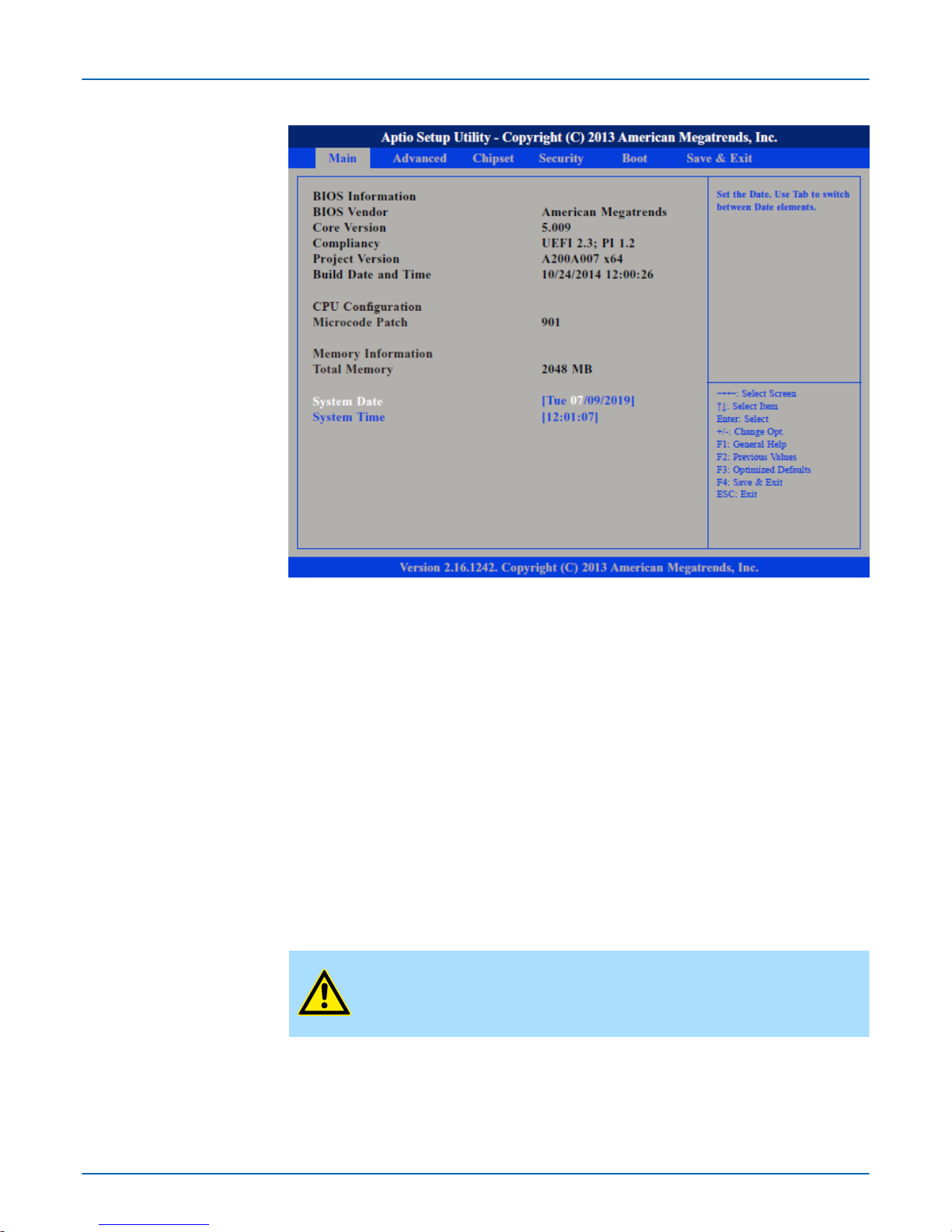
The date format is day month/date/year an.
n Day displays a day, from Monday to Sunday.
n Month displays the month, from January to December.
n Date displays the date, from 1 to 31.
n Year displays the year, from 1999 to 2099.
The time format is hour:minute:second.
n hour displays hours from 00 to 23.
n minute displays minutes from 00 to 59.
n second displays seconds from 00 to 59.
4.3 Advanced
This menu allows you to configure the system's extended functions. Here you can configure the CPU and the periphery
.
CAUTION!
Setting incorrect field values may cause the system to malfunction.
System Date
System Time
VIPA HMI
BIOS setup
Advanced
HB160 | PPC | 67K-RRJ0 | en | 18-30 40
Page 41
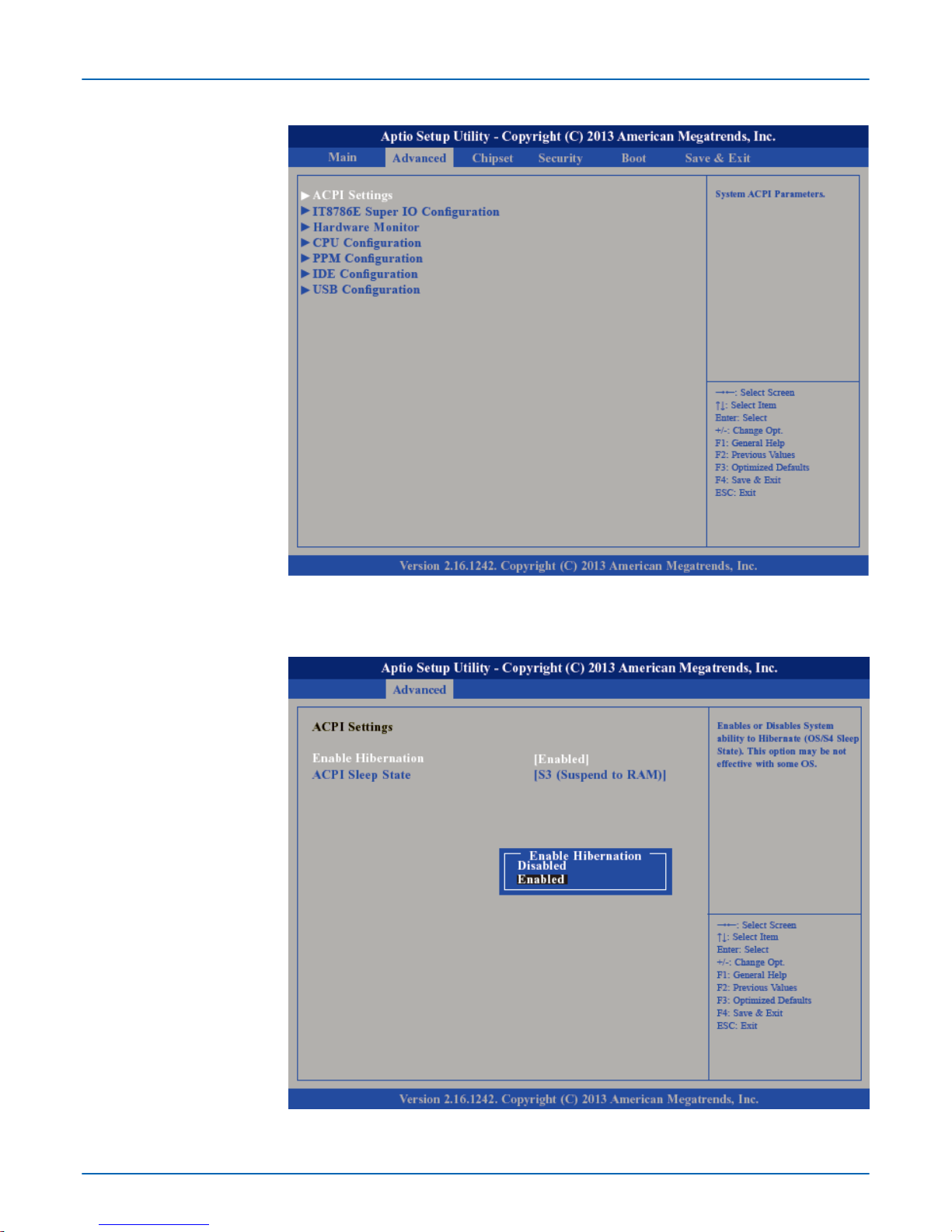
This section is used to configure Advanced Configuration and Power Interface (ACPI)
Settings.
Submenu "ACPI Settings"
VIPA HMI
BIOS setup
Advanced
HB160 | PPC | 67K-RRJ0 | en | 18-30 41
Page 42
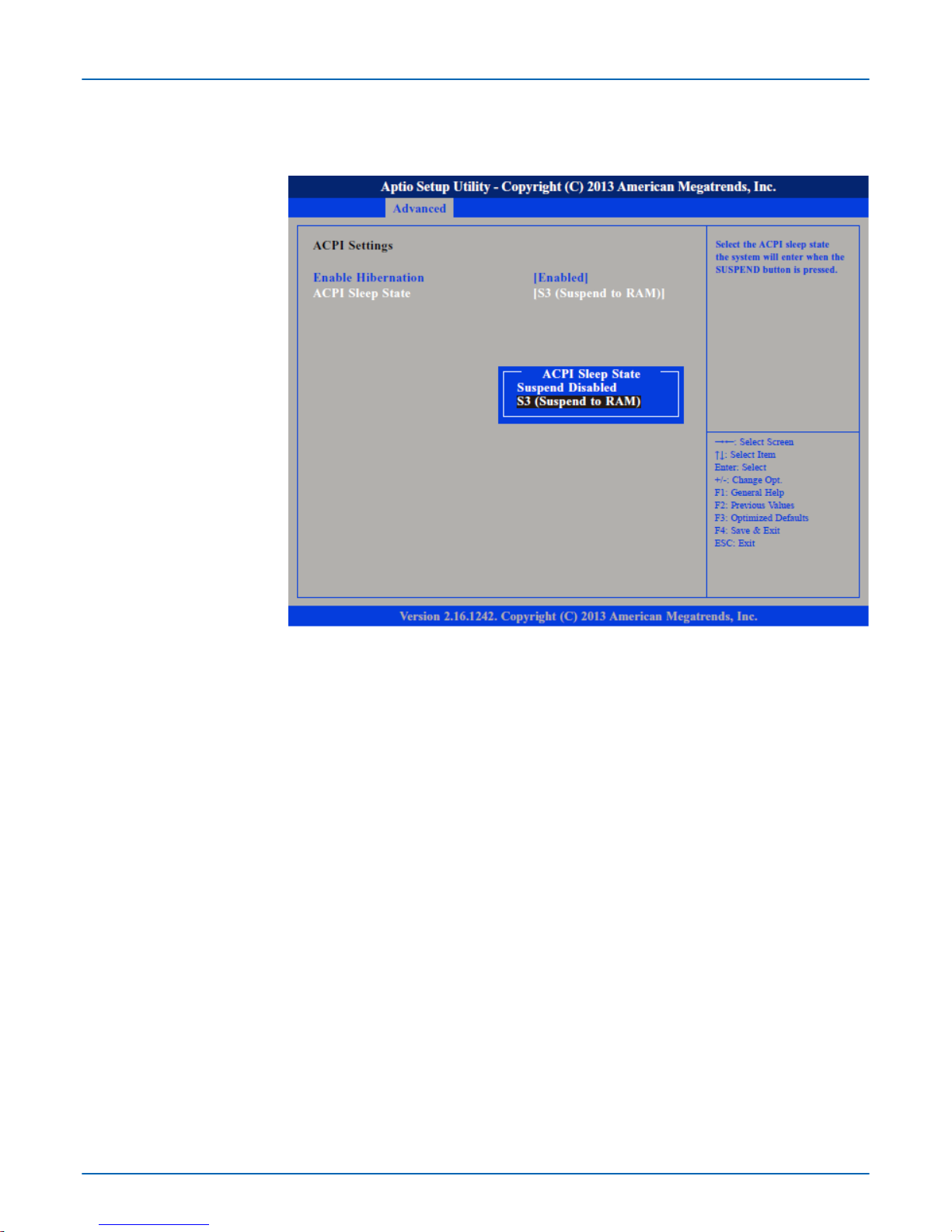
Enables or disables (default) system ability to hibernate (S4 Sleep State).
Select the highest ACPI Sleep State the system will enter when the suspend button is
pressed.
Suspend Disabled - Sleep state disabled
S3 (Suspend to RAM) - Standby mode enabled, Windows saves the system state in
RAM.
This section is used to configure serial ports.
Enable Hibernation
ACPI Sleep State
Submenu "IT8786E Super
IO Configuration"
VIPA HMI
BIOS setup
Advanced
HB160 | PPC | 67K-RRJ0 | en | 18-30 42
Page 43
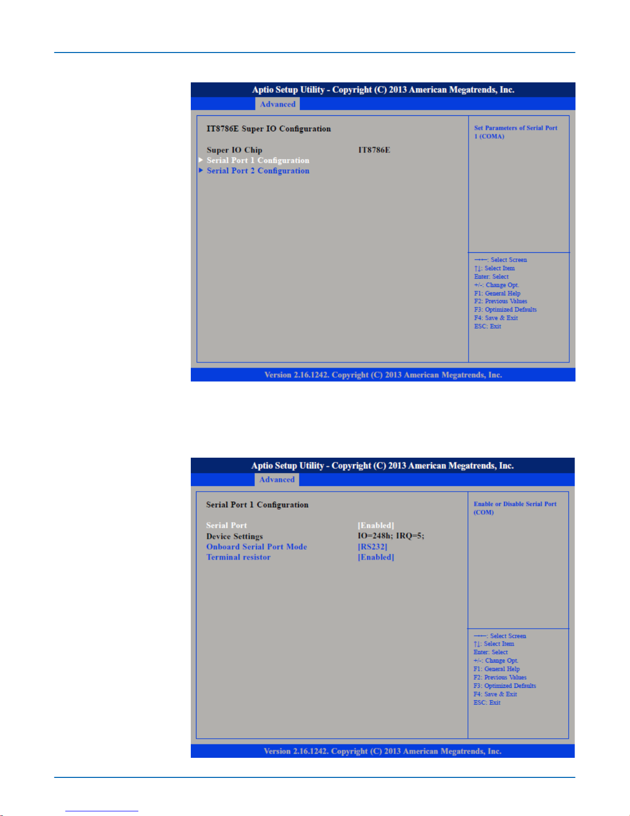
Displays the Super I/O Chip used on the board.
This section is used to configure serial port 1.
Super IO Chip
Submenu "Serial Port 1
Configuration"
VIPA HMI
BIOS setup
Advanced
HB160 | PPC | 67K-RRJ0 | en | 18-30 43
Page 44
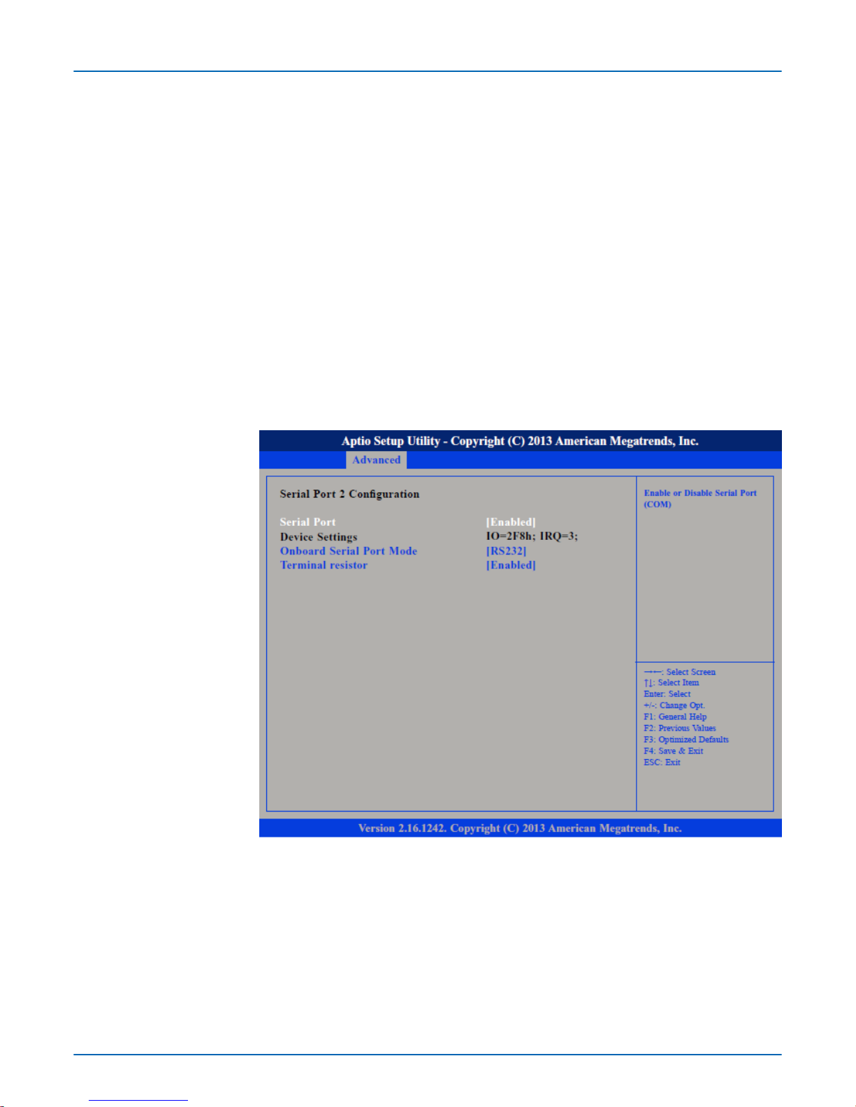
Enables or disables the serial port.
Disabled - Serial port is not available
Enabled - (default) Serial port is available
Selects an optimal setting for the Super IO Device.
This field is used to configure the mode of serial port 0 as RS232 (default), RS422,
RS485 or RS485 AUT
O.
Enables or disables the terminal resistor.
Disabled - Terminal resistor not activated
Enabled - (default) Terminal resistor activated
This section is used to configure serial port 2.
Enables or disables the serial port.
Disabled - Serial port is not available
Enabled - (default) Serial port is available
Selects an optimal setting for the Super IO Device.
Serial Port
Device Settings
Onboard Serial Port Mode
Terminal resistor
Submenu "Serial Port 2
Configuration"
Serial Port
Device Settings
VIPA HMI
BIOS setup
Advanced
HB160 | PPC | 67K-RRJ0 | en | 18-30 44
Page 45
This field is used to configure the mode of serial port 1 as RS232, RS422 (default),
RS485 or RS485 AUT
O.
Enables or disables the terminal resistor.
Disabled - Terminal resistor not activated
Enabled - (default) Terminal resistor activated
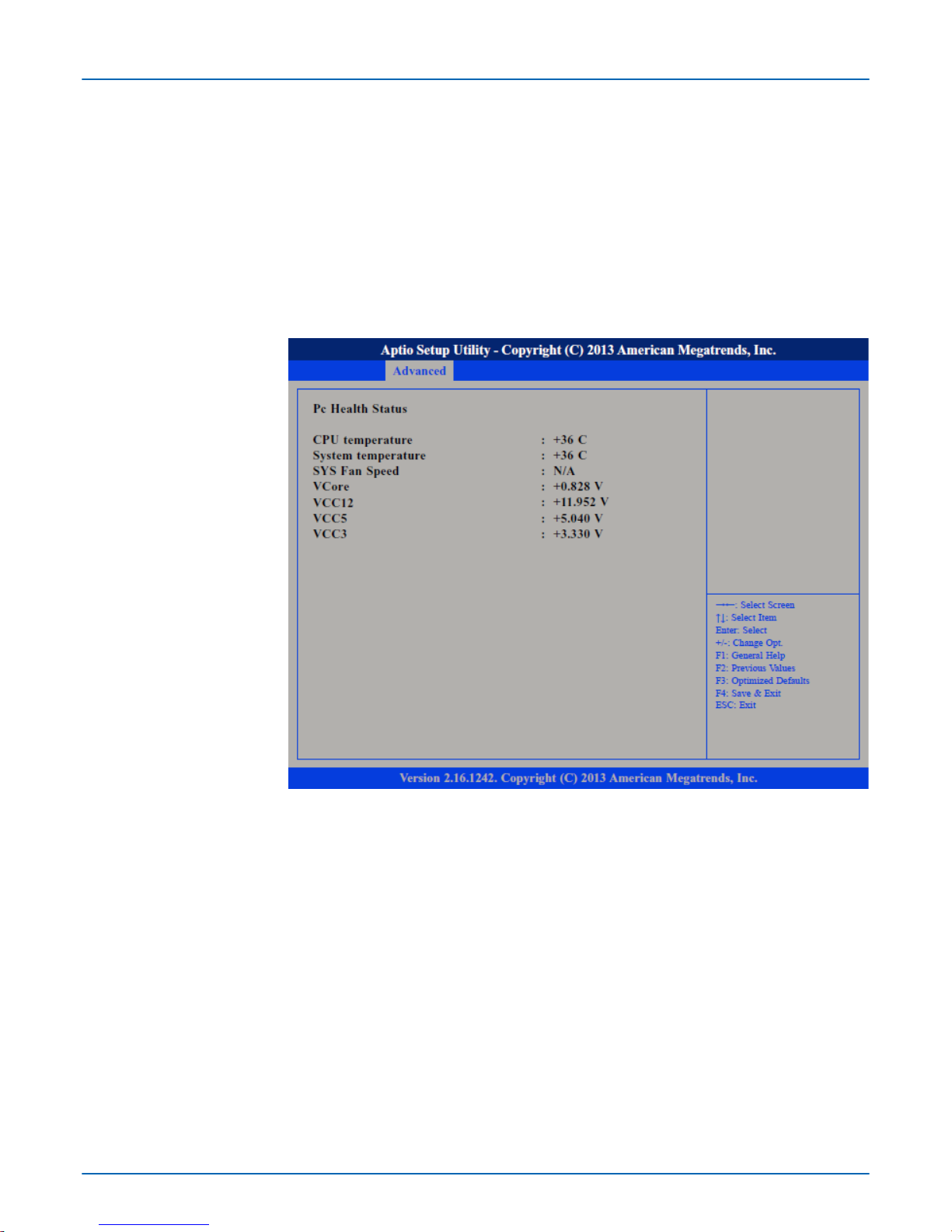
This section ‘Pc Health Status’ is used to configure the hardware temperature and voltages.
This section is used to configure the CPU.
Onboard Serial Port Mode
Terminal resistor
Submenu "H/W Monitor"
Submenu "CPU Configuration"
VIPA HMI
BIOS setup
Advanced
HB160 | PPC | 67K-RRJ0 | en | 18-30 45
Page 46
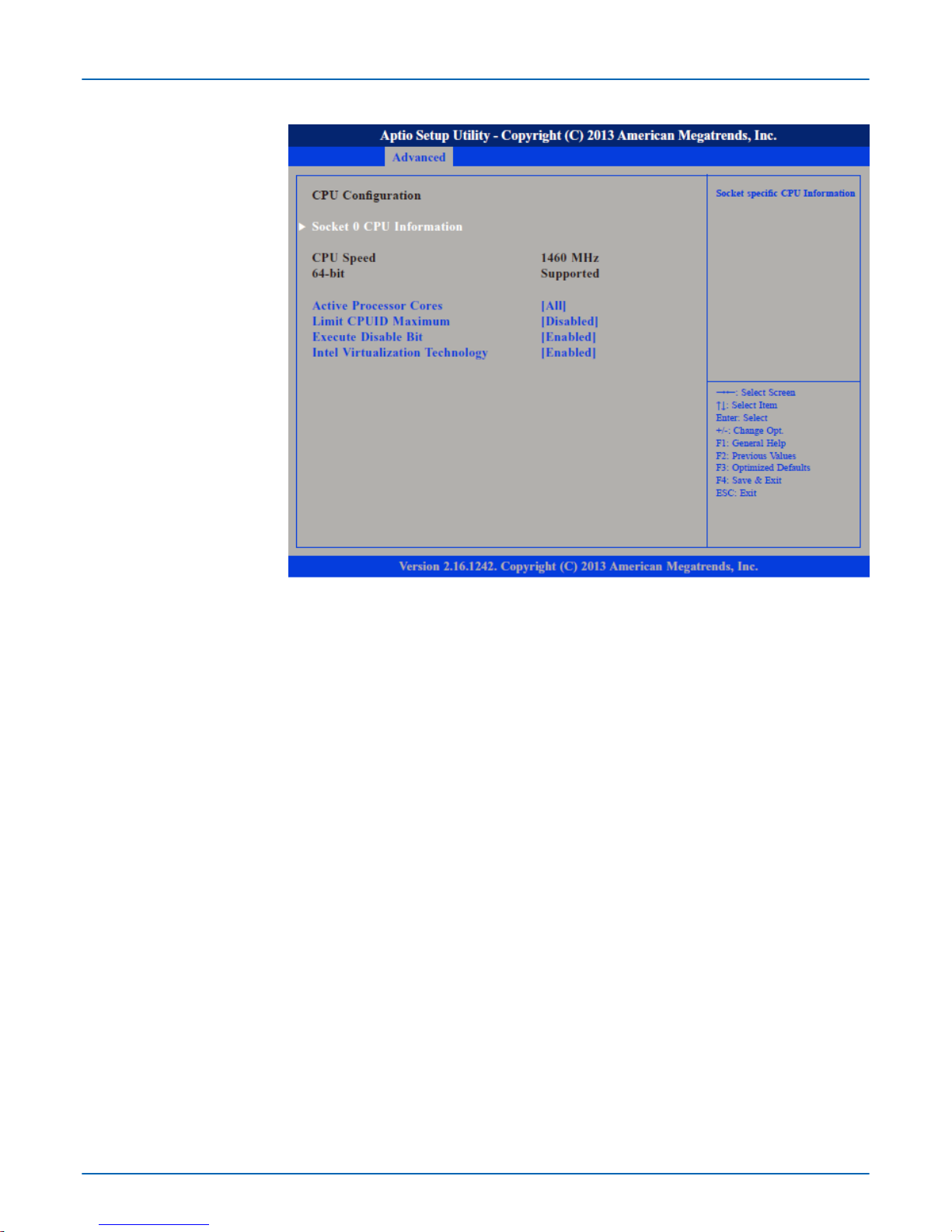
Select the number of cores to enable in each processor package.
The CPUID instruction of some newer CPUs will return a value greater than 3. The
default is disabled because this problem does not exist in the Windows series operating
systems. If you are using an operating system other than Windows, this problem may
occur
. To avoid this problem, enable this field to limit the return value to 3 or less than 3.
Disabled - (default) All of the CPUID functions are supported.
Enabled - Limit the return value to 3 or less than 3.
XD can prevent certain classes of malicious buffer overflow attacks.
Enabled - Permit the switching on of the execute disable function by the OS.
Disabled - Prevents the switching on of the execute disable function by the OS; it will
force the XD feature flag to always return to 0.
Enables or disables Intel Virtualization Technology.
Display information on the CPU installed on socket 0.
Active Processors Cores
Limit CPUID Maximum
Execute Disable Bit
Intel® V
irtualization Tech-
nology
Submenu "Socket 0 CPU
Information"
VIPA HMI
BIOS setup
Advanced
HB160 | PPC | 67K-RRJ0 | en | 18-30 46
Page 47
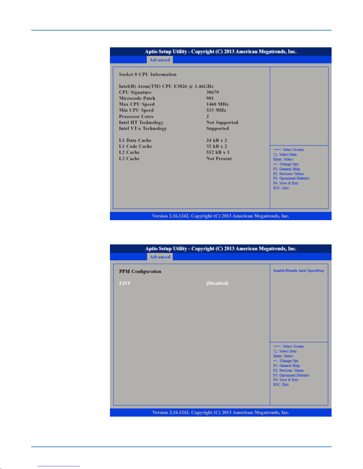
This section is used to configure the Processor Power Management (PPM) configuration.Submenu "PPM Configu-
ration"
VIPA HMI
BIOS setup
Advanced
HB160 | PPC | 67K-RRJ0 | en | 18-30 47
Page 48
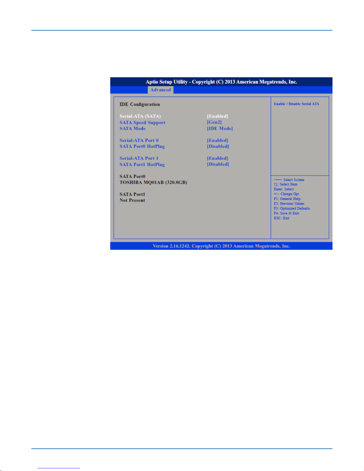
Enables or disables Intel® SpeedStep.
This section is used to configure the IDE devices.
Enables or disables SATA controller.
Configures the SA
TA controller as Gen1 or Gen2.
Configures the SATA as IDE or AHCI mode.
IDE - This option configures the serial ATA drives as parallel ATA physical storage
device.
AHCI - This option configures the serial ATA drives to use AHCI (Advanced Host Con-
troller Interface). AHCI allows the storage driver to enable the advanced serial
ATA features which will increase storage performance.
Enables or disables SATA port 0.
Enables or disables Hot Pluggable Support on SATA port 0.
Enables or disables SATA port 1.
Enables or disables Hot Pluggable Support on SATA port 1.
EIST
Submenu "IDE Configuration"
Serial-ATA (SATA)
SATA Speed Support
SATA Mode
Serial-ATA Port 0
SATA Port0 HotPlug
Serial-ATA Port 1
SATA Port1 HotPlug
VIPA HMI
BIOS setup
Advanced
HB160 | PPC | 67K-RRJ0 | en | 18-30 48
Page 49
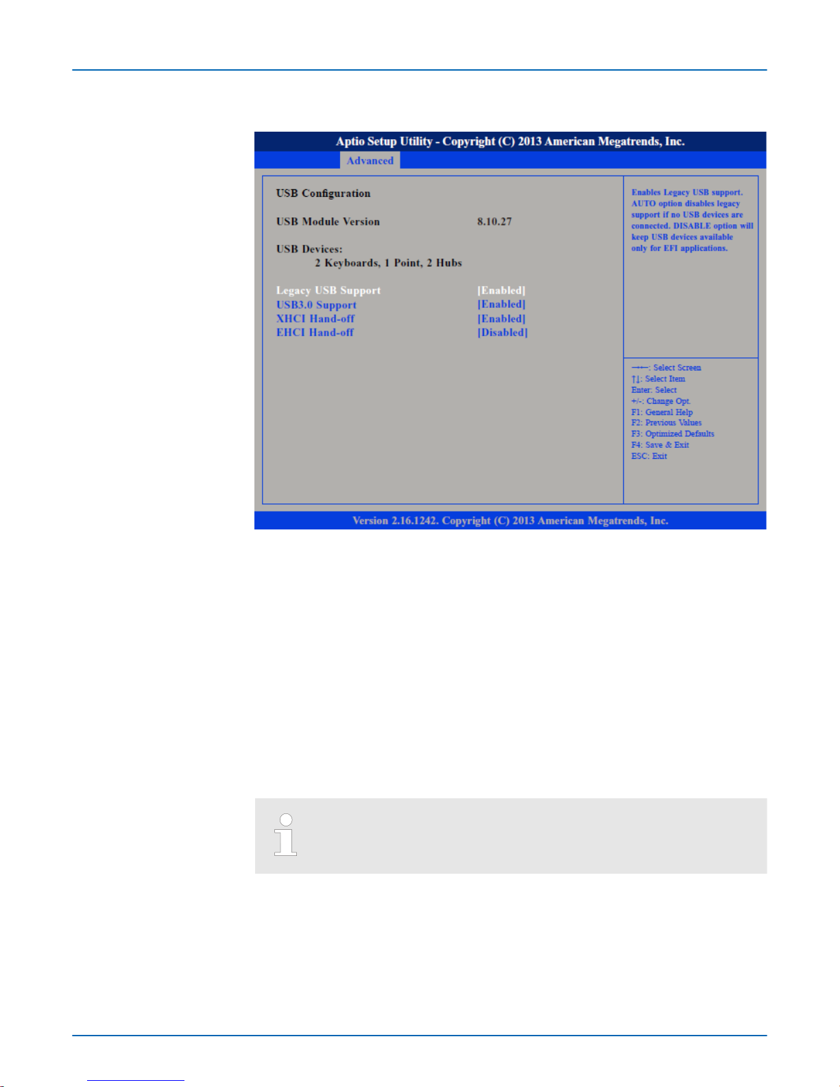
This section is used to configure USB devices, such as keyboard, mouse and hub.
Support of USB keyboard, mouse and storage media in EFI and DOS environments.
Enable - (Default) Enables Legacy USB.
Auto - Disables Legacy USB Support when no USB devices are connected.
Disable - Keeps USB devices available only for EFI applications.
Enabled - (Default) Enables USB 3.0 controller support.
Disabled - Disables USB 3.0 controller support.
Enabled - Enables XHCI (USB 3.0) or EHCI (USB 2.0) support.
Disabled - Disables XHCI (USB 3.0) or EHCI (USB 2.0) support.
When installing Windows 7 from USB, USB 3.0 will not be supported.
Please disable XHCI and enable EHCI to allow USB installation of W
in-
dows 7.
Submenu "USB Configuration"
Legacy USB Support
USB3.0 Support
XHCI Hand-off and EHCI
Hand-of
f
VIPA HMI
BIOS setup
Advanced
HB160 | PPC | 67K-RRJ0 | en | 18-30 49
Page 50
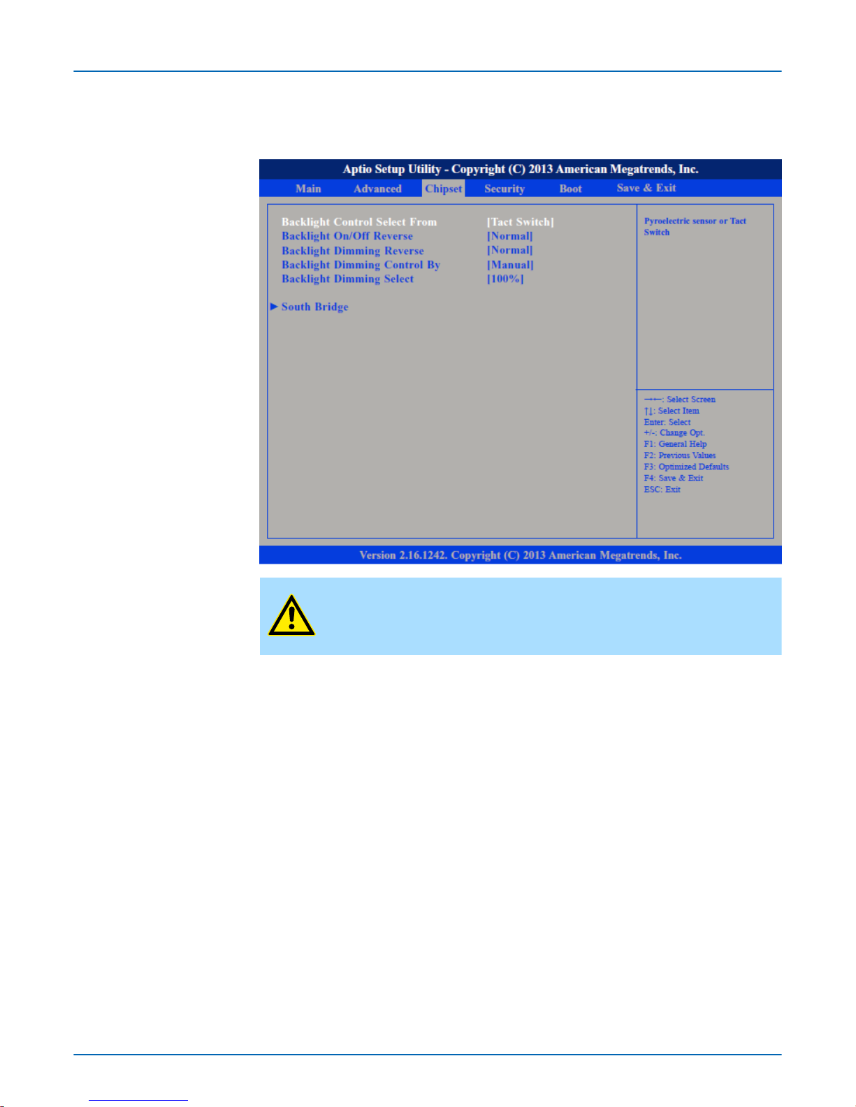
4.4 Chipset
This section is used to configure the system based on the specific features of the chipset.
CAUTION!
Setting incorrect field values may cause the system to malfunction.
The available options are ‘Pyroelectric sensor
’ and ‘Tact Switch’ . The default setting is
‘Tact Switch’ .
Please configure this option only when changing the panel, otherwise the display may not
work.
The options are ‘Tact Switch’ , ‘Manual’ and ‘Light Sensor’ . The default setting is
‘Manual’ and the Backlight option below will be configurable.
Adjust the brightness of the backlight.
This field is used to configure the South Bridge chipset.
Backlight Control Select
From
Backlight On/Off Reverse
Backlight Dimming Control By
Backlight Dimming Select
Submenu "South Bridge"
VIPA HMI
BIOS setup
Chipset
HB160 | PPC | 67K-RRJ0 | en | 18-30 50
Page 51
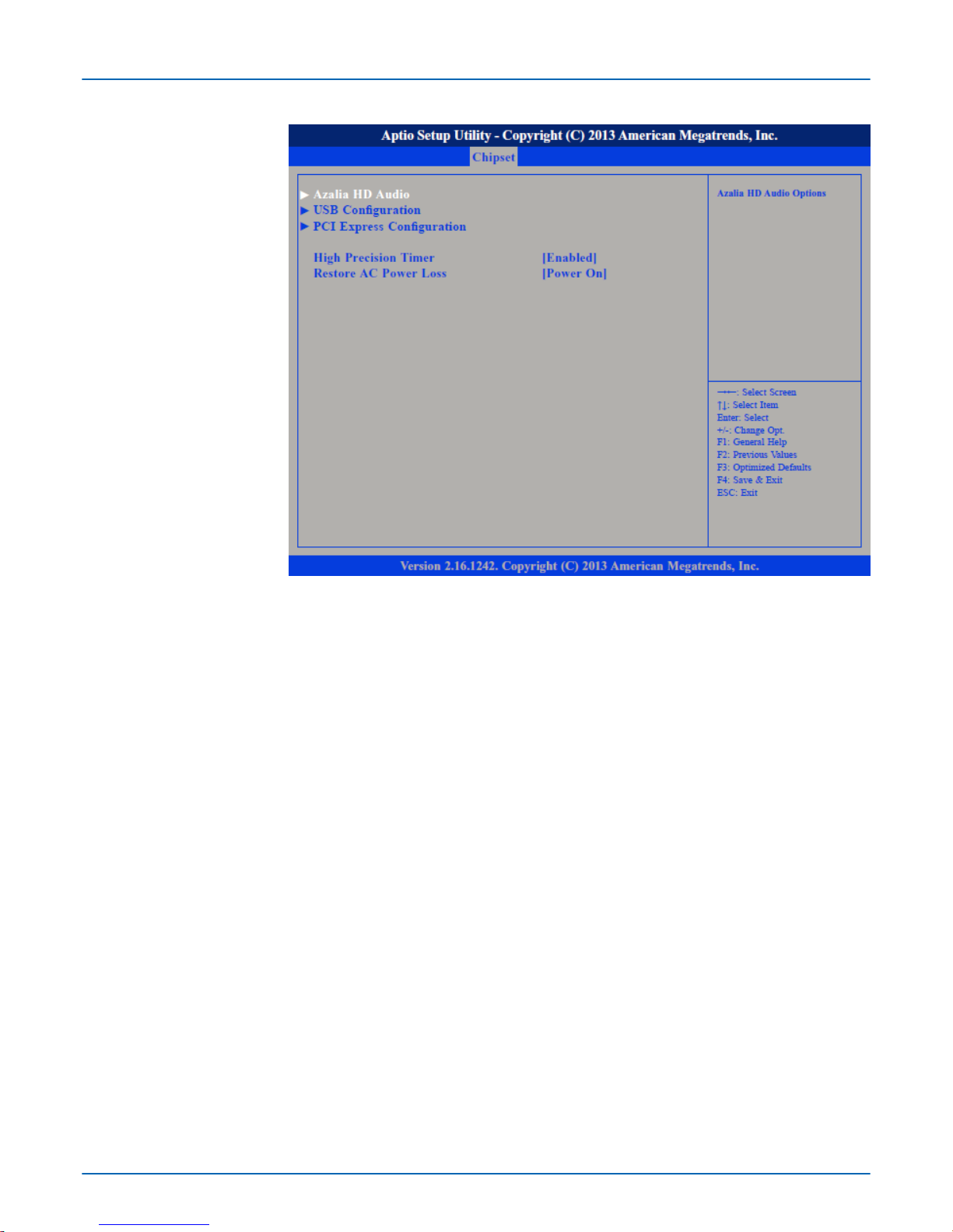
This section is used to configure High Precision Event T
imer.
System response when power returns after an AC power failure.
Last State - The system will return to the state where you left off before power failure
occurs.
Power Off - The system’s power is off. You must press the power button to Power On
the system.
Power On - (default) The system will automatically Power On.
This section disables Azalia or enables HD Audio.
High Precision Timer
Restore AC Power Loss
Submenu "Azalia HD
Audio"
VIPA HMI
BIOS setup
Chipset
HB160 | PPC | 67K-RRJ0 | en | 18-30 51
Page 52
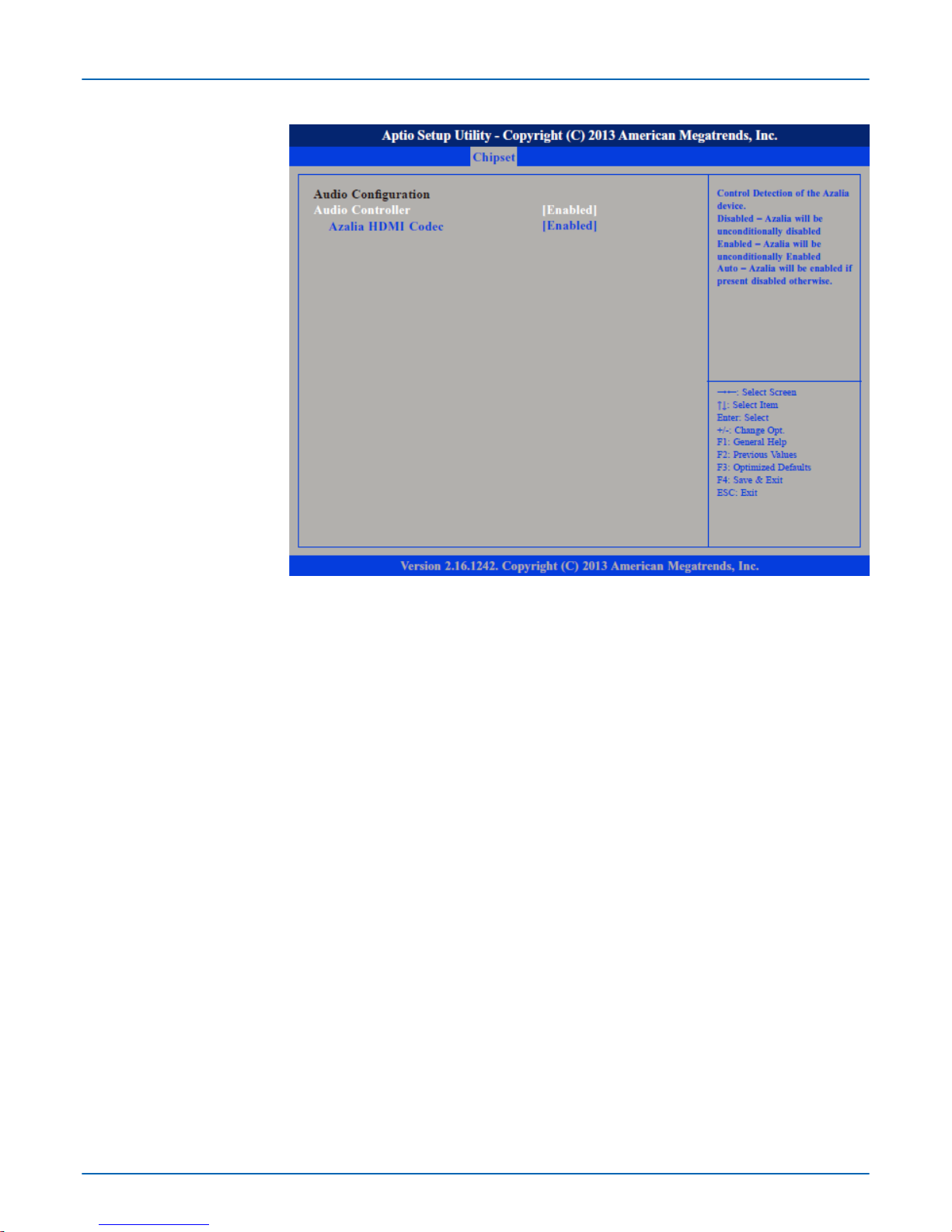
Control detection of the Azalia device.
Disabled - Azalia will be unconditionally disabled.
Enabled - Azalia will be unconditionally enabled.
Enables or disables internal HDMI Codec for Azalia.
Audio Controller
Azalia HDMI Codec
VIPA HMI
BIOS setup
Chipset
HB160 | PPC | 67K-RRJ0 | en | 18-30 52
Page 53
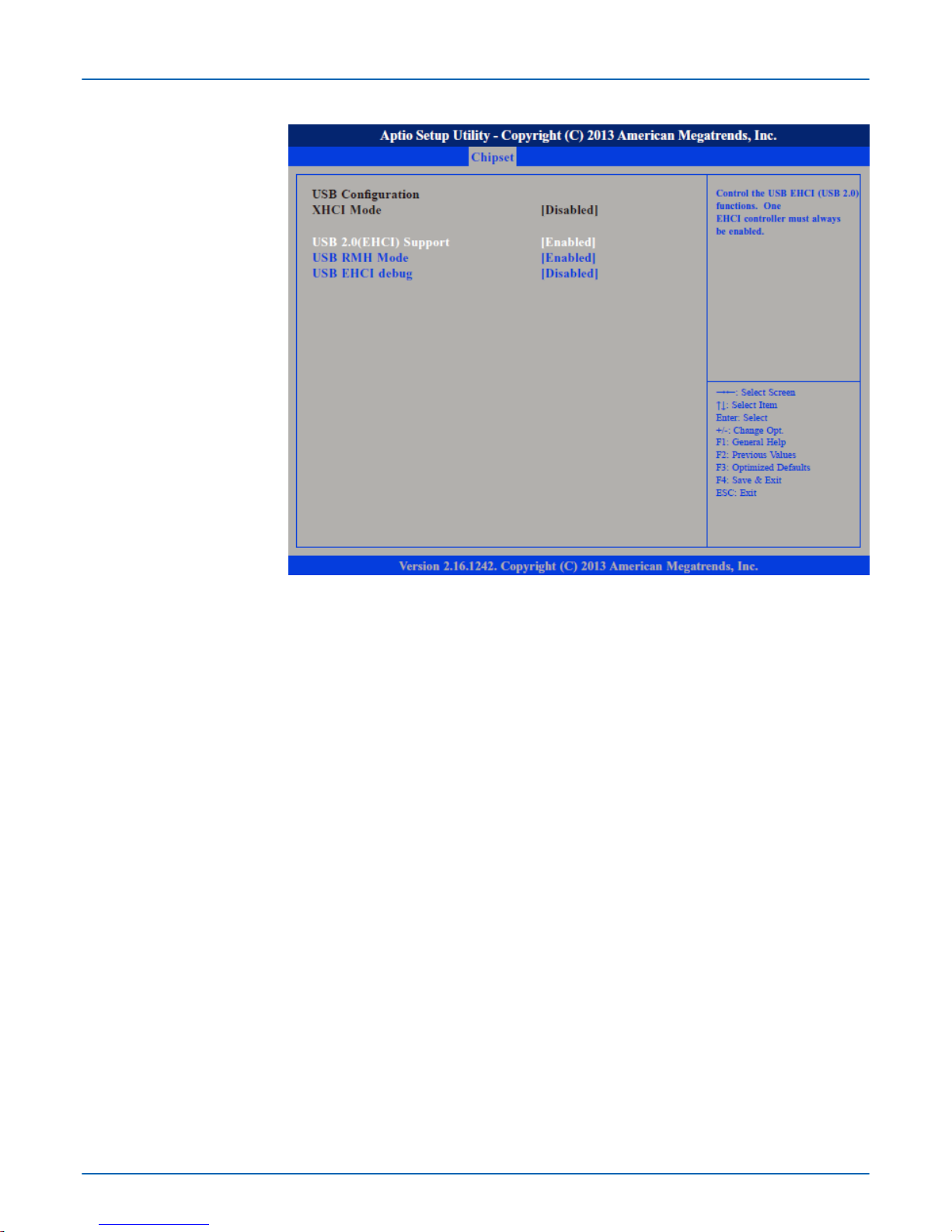
Enables or disables the Enhanced Host Controller Interface (USB 2.0), one EHCI controller must always be enabled.
Enables or disables PCH USB rate matching hubs mode.
Enables or disables PCH EHCI debug capability
.
Submenu "USB Configuration"
USB 2.0(EHCI) Support
USB RMH Mode
USB EHCI debug
VIPA HMI
BIOS setup
Chipset
HB160 | PPC | 67K-RRJ0 | en | 18-30 53
Page 54
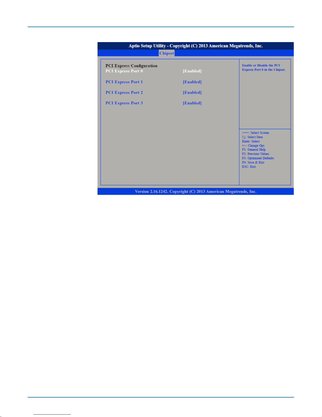
Enables or disables the PCI Express ports 0 ... 3 on the chipset.
4.5
Security
If only the Administrator's password is set, then this only limits access to setup and is only
asked for when entering setup.
If only the User's password is set, then this is a power on password and must be entered
to boot or enter setup. In Setup the user will have administrator rights.
Submenu "PCI Express
Configuration"
PCI Express Port 0 ... PCI
Express Port 3
If ONLY the Administrator's password is set
If ONLY the User's password is set
VIPA HMI
BIOS setup
Security
HB160 | PPC | 67K-RRJ0 | en | 18-30 54
Page 55
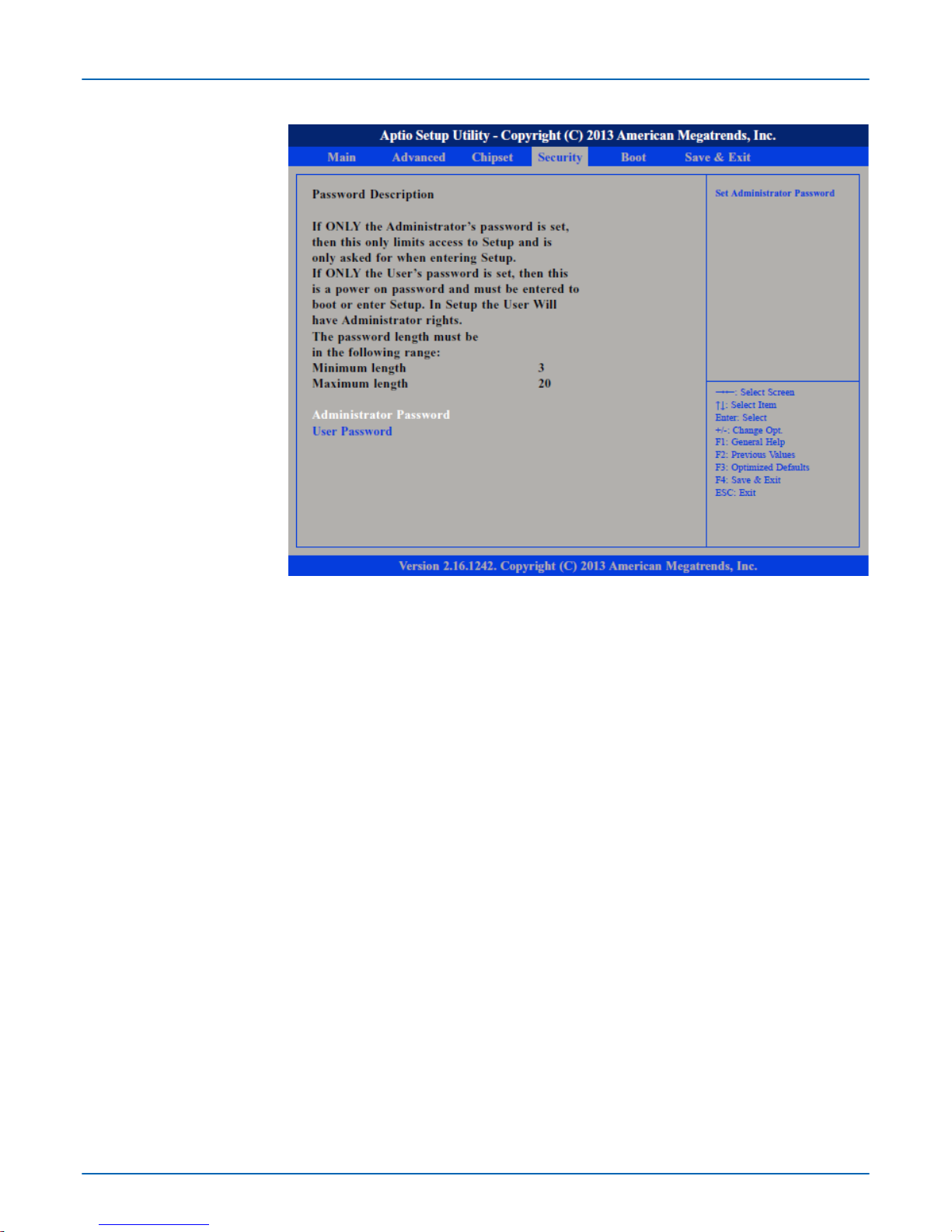
Select this to reconfigure the administrator’s password. Your password must contain at
least 3 characters and should be maximal 20 characters long.
Select this to reconfigure the user
’s password. Your password must contain at least 3
characters and should be maximal 20 characters long.
Administrator Password
User Password
VIPA HMI
BIOS setup
Security
HB160 | PPC | 67K-RRJ0 | en | 18-30 55
Page 56
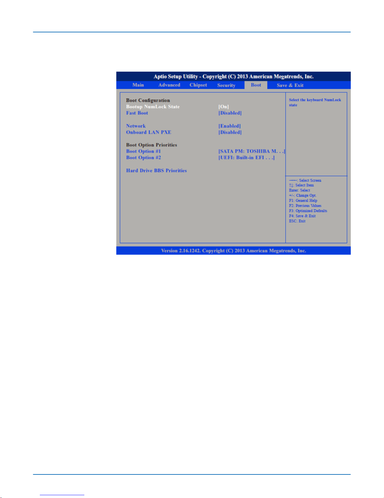
4.6 Boot
This section is used to configure the boot features.
This allows you to determine the default state of the numeric keypad.
On - (default) The function of the numeric keypad is the number keys.
Off - The function of the numeric keypad is the arrow keys.
When enabled, the BIOS will shorten or skip some check items during POST. This will
decrease the time needed to boot the system.
Controls the execution of UEFI and legacy PXE OpROM.
Enables or disables the boot option for legacy network devices connected to LAN1 or
LAN2.
Disabled - (default) Starts no LAN PXE ROM
Enabled - Starts the LAN PXE ROM, to be able to boot about PXE
Adjust the boot sequence of the system.
Sets the order of the legacy devices in this group.
Bootup NumLock State
Fast Boot
Network
Onboard LAN PXE
Boot Option Priorities
Hard Drive BBS Priorities
VIPA HMI
BIOS setup
Boot
HB160 | PPC | 67K-RRJ0 | en | 18-30 56
Page 57
4.7 Save and Exit
VIPA HMI
BIOS setup
Save and Exit
HB160 | PPC | 67K-RRJ0 | en | 18-30 57
Page 58

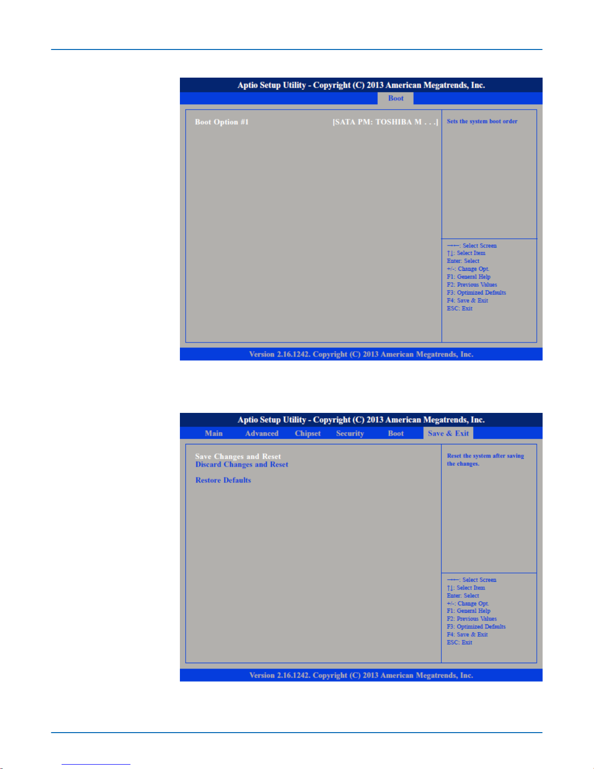
To save the changes and reset, select this field then press [Enter]. A dialog box will
appear
. Confirm by selecting [Yes]. A restart follows and the new settings become effec-
tive.
To exit the Setup utility and reboot the system without saving the changes, select this field
then press [Enter]. You may be prompted to confirm again before exiting. The BIOS setup
exits and a restart follows.
To restore the BIOS to default settings, select this field then press [Enter]. A dialog box
will appear. Confirm by selecting [Yes].
To save the changes and exit the setup utility press [F4].
To exit the Setup utility without saving the changes [Esc]. The BIOS setup exits and the
POST continued.
Save Changes and Reset
Discard Changes and
Reset
Restore Defaults
Save Changes and Exit
Discard Changes and Exit
VIPA HMI
BIOS setup
Save and Exit
HB160 | PPC | 67K-RRJ0 | en | 18-30 58
Page 59
5 Installation guidelines
5.1 Basic rules for the EMC-equitable assembly of installations
The installation guidelines contain information about the interference free deployment of a
PLC system. There is the description of the ways, interference may occur in your PLC,
how you can make sure the electromagnetic compatibility (EMC), and how you manage
the isolation.
Electromagnetic compatibility (EMC) means the ability of an electrical device, to function
error free in an electromagnetic environment without being interfered respectively without
interfering the environment.
The components of VIPA are developed for the deployment in industrial environments
and meets high demands on the EMC. Nevertheless you should project an EMC planning
before installing the components and take conceivable interference causes into account.
Electromagnetic interferences may interfere your control via different ways:
n Electromagnetic fields (RF coupling)
n Magnetic fields with power frequency
n Bus system
n Power supply
n Protected earth conductor
Depending on the spreading medium (lead bound or lead free) and the distance to the
interference cause, interferences to your control occur by means of dif
ferent coupling
mechanisms.
There are:
n galvanic coupling
n capacitive coupling
n inductive coupling
n radiant coupling
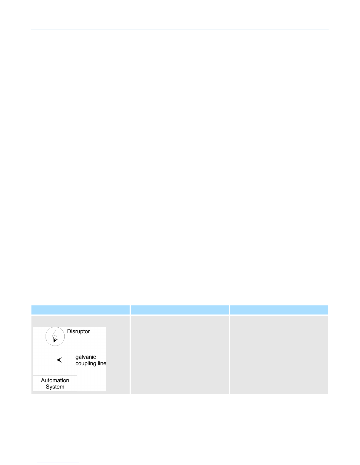
The following table shows the four different coupling mechanisms, their causes and possible interference sources.
Coupling mechanism Cause Typical source
Galvanic coupling Galvanic or metallic coupling always
occurs, when two current circuits have
a common line.
n Pulsed devices (Net influence from
transducers and foreign net
devices)
n Starting motors
n Dif
ferent potential of component
cubicles with common current
supply
n Static discharges
General
What does EMC mean?
Possible interference
causes
Coupling mechanisms and
interference sources
VIPA HMI
Installation guidelines
Basic rules for the EMC-equitable assembly of installations
HB160 | PPC | 67K-RRJ0 | en | 18-30 59
Page 60
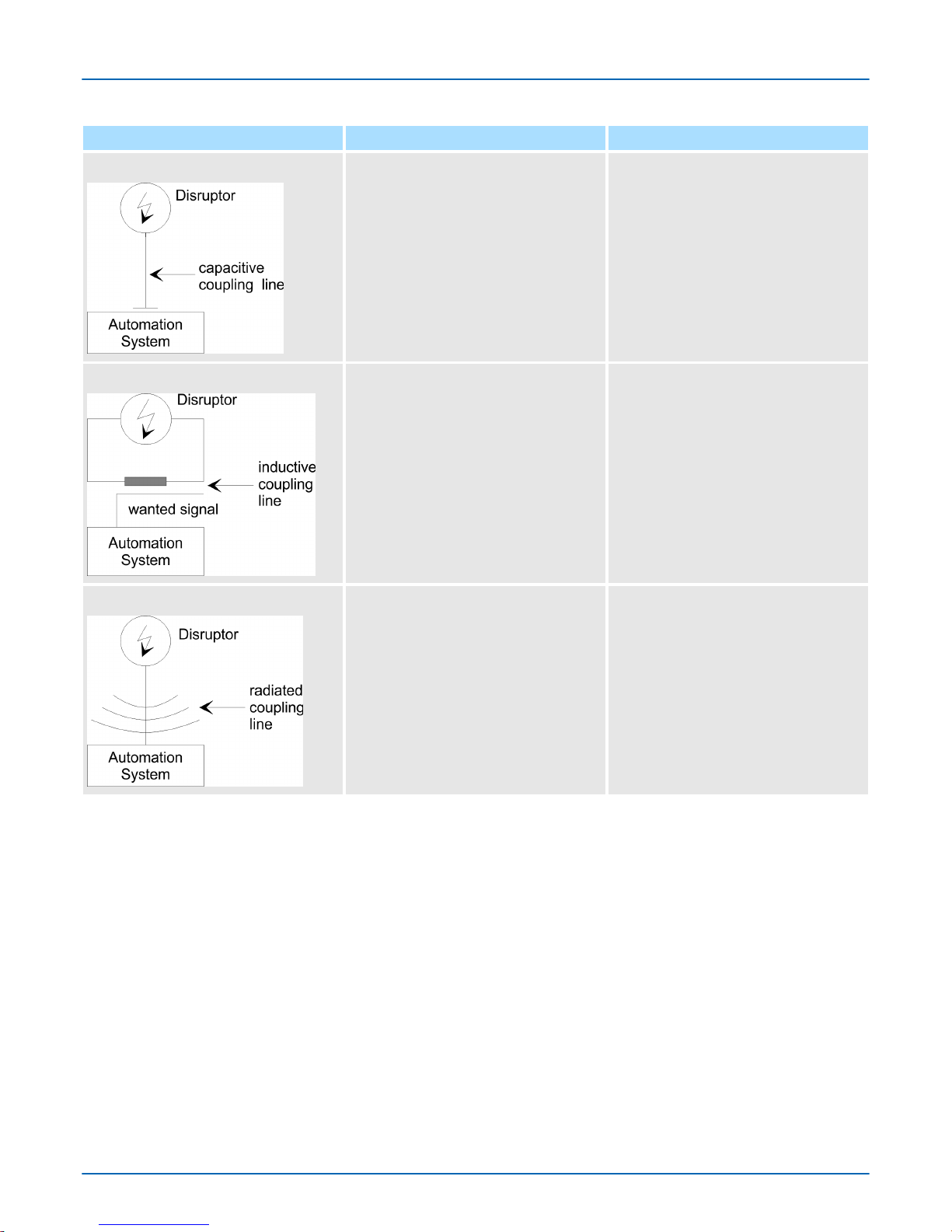
Coupling mechanism Cause Typical source
Capacitate coupling Capacitate or electric coupling occurs
between conductors with dif
ferent
potential. The coupling is proportionate to the temporal change of the
voltage.
n Interference through parallel signal
lines
n Static discharge of the personnel
n Contactors
Inductive coupling
Inductive or magnetic coupling occurs
between two current active line loops.
The magnetic flows associated with
the currents induct interference voltages. The coupling is proportional to
the time related change of the current.
n Transducers, motors, electric
welding devices
n Parallel net cables
n Cables with toggled currents
n Signal cable with high frequency
n Unused coils
Radiate power coupling
One talks of radiate power coupling,
when an electromagnetic wave meets
a line circuit. The hit of the wave
inducts currents and voltages.
n Sender in the neighbourhood (e.g.
walkie-talkie)
n Sparking lines (sparking plugs,
collector of electric motors,
welding devices)
In the most times it is enough to take care of some elementary rules to guarantee the
EMC. Please regard the following basic rules when installing your PLC.
n T
ake care of a correct area-wide grounding of the inactive metal parts when installing
your components.
– Install a central connection between the ground and the protected earth conductor
system.
– Connect all inactive metal extensive and impedance-low.
– Please try not to use aluminium parts. Aluminium is easily oxidizing and is there-
fore less suitable for grounding.
n When cabling, take care of the correct line routing.
– Organize your cabling in line groups (high voltage, current supply, signal and data
lines).
– Always lay your high voltage lines and signal respectively data lines in separate
channels or bundles.
– Route the signal and data lines as near as possible beside ground areas (e.g.
suspension bars, metal rails, tin cabinet).
Basic rules for EMC
VIPA HMI
Installation guidelines
Basic rules for the EMC-equitable assembly of installations
HB160 | PPC | 67K-RRJ0 | en | 18-30 60
Page 61

n Proof the correct fixing of the lead isolation.
–
Data lines must be laid isolated.
– Analog lines must be laid isolated. When transmitting signals with small ampli-
tudes the one sided laying of the isolation may be favourable.
– Lay the line isolation extensively on an isolation/protected earth conductor rail
directly after the cabinet entry and fix the isolation with cable clamps.
– Make sure that the isolation/protected earth conductor rail is connected impe-
dance-low with the cabinet.
– Use metallic or metallised plug cases for isolated data lines.
n In special use cases you should appoint special EMC actions.
– Consider to wire all inductivities with erase links.
– Please consider luminescent lamps can influence signal lines.
n Create a homogeneous reference potential and ground all electrical operating sup-
plies when possible.
– Please take care for the targeted employment of the grounding actions. The
grounding of the PLC serves for protection and functionality activity.
– Connect installation parts and cabinets with your PLC in star topology with the
isolation/protected earth conductor system. So you avoid ground loops.
– If there are potential differences between installation parts and cabinets, lay suffi-
ciently dimensioned potential compensation lines.
VIPA HMI
Installation guidelines
Basic rules for the EMC-equitable assembly of installations
HB160 | PPC | 67K-RRJ0 | en | 18-30 61
Page 62

5.2 EMC-equitable assembly
Mostly
, measures for suppressing interference voltages are only taken, when the control
is already in commission and the perfect receive of a wanted signal is disturbed. Causes
for such interference's are in the most cases inadequate reference potentials, coming
from mistakes at the device assembly and installation.
When assembling the devices, you have to ensure the large-surface grounding of the
inactive metal parts. A correctly done grounding supports an unambiguous reference
potential for the control and reduces the impact of coupled interferences.
Grounding means the conducting connection of all inactive metal parts. The sum of all
interconnected inactive parts is called ground.
Inactive parts are all conductive parts electrically separated from all active parts by
means of a basic isolation and that may only get voltage in case of an error.
The ground must not adopt dangerous contact voltage even in case of an error. Thus you
have to connect the ground with the protected earth conductor. To avoid ground loops,
local distant ground constructions (cubicles, construction and machine parts) have to be
connected with the protected earth conductor system in star-topology.
Please regard at grounding:
n Connect the inactive metal parts as carefully as the active ones.
n T
ake care of impedance-low metal-metal-connections, e.g. with large-surface and well
conductive contacts.
n If you include coated or anodized metal parts in the grounding, you have to come
through the isolating protection layers. For this you may use special contact washers
or remove the isolation layer.
n Protect the connection points from corrosion, e.g. with grease.
n Moveable grounding parts (e.g. cubicle doors) have to be connected via flexible
ground strips. The ground strips should be short and have a large surface, because
the surface is decisive for the diversion of high frequency interferences.
Guidelines for assembling
and grounding of inactive
metal parts
VIPA HMI
Installation guidelines
EMC-equitable assembly
HB160 | PPC | 67K-RRJ0 | en | 18-30 62
Page 63

5.3 EMC-equitable cabling
Content of this section is the line routing of bus, signal and supply lines. Object of the line
routing is to suppress the "slurring" at parallel lines.
For an EMC-equitable routing of the lines it is convenient to divide the cables in dif
ferent
groups and install each group itself:
Group A
n screened bus and data lines
n screened analog lines
n unshielded lines for direct voltage £60V
n unshielded lines for alternating voltage £25V
n Coaxial cables for monitors
Group B
n unshielded lines for direct voltage >60V and £400V
n unshielded lines for alternating voltage >25V and £400V
Group C
n unshielded lines for direct and alternating voltage >400V
Group D
n Lines for H1 respectively TCP/IP
Following the table you may see the conditions for the cabling of the line groups by combining the single groups:
Group A Group B Group C Group D
Group A [1] [2] [3] [4]
Group B [2] [1] [3] [4]
Group C [3] [3] [1] [4]
Group D [4] [4] [4] [1]
[1] The lines may be installed in common bundles or cable trusses.
[2] The lines have to be installed in different bundles or cable trusses (without min.
distance).
[3] The lines have to be installed in different bundles or cable trusses inside of
cubicles and outside of the cubicle but inside the building in separated cable
trusses with a min. distance of 10cm.
[4] The lines have to be installed in different bundles or cable trusses with a min.
distance of 50cm.
Wherever possible, exterior cabling should be installed on metallic cable trays. A galvanic
connection must be provided for joints between cable trays. Y
ou must abide by the appli-
cable lightning protection and grounding regulations when installing exterior cables.
Line routing
Line routing inside and
outside of cubicles
Combination of groups
Line routing outside of
buildings
VIPA HMI
Installation guidelines
EMC-equitable cabling
HB160 | PPC | 67K-RRJ0 | en | 18-30 63
Page 64

CAUTION!
Where cables and signal lines for PLC equipment are installed outside of
buildings, the conditions for internal and external lightning protection must
be satisfied.
– Exterior lines should either be installed in metallic conduit pipes that
is grounded on both ends or in steel-reinforced concrete cable trunks
with continuously connected reinforcing.
–
Signal lines should be protected against overvoltage by varistors or
by lightning arrester filled with rare gas.
– Install these protective elements at the location where the cables
enter the building.
Any lightning protection system must be based on an individual assessment of the entire plant. For questions please contact VIP
A GmbH.
Potential differences can occur between different sections when controllers and peripheral equipment are connected by means of non-isolated connections or the screens of
screened cables are connected at both ends and grounded on dif
ferent sections of the
plant. One reason for a potential difference can be that different sections of the plant are
powered from different power sources. These potential differences must be reduced by
means of equipotential bonding conductors to ensure that the electronic equipment
employed on the plant operates properly.
n The lower the impedance of the equipotential bonding conductor
, the higher the effec-
tiveness of potential equalization.
n The impedance of the equipotential bonding conductor must not exceed 10% of the
impedance of the screen where screened signal lines are connected between the different sections of the plant and the screening is connected to ground/neutral on both
sides.
n The cross-sectional area of the equipotential bonding conductor must be calculated to
carry the maximum equalization current. The following cross-sections have been successfully employed:
– 16mm2 Cu for equipotential bonding conductors up to 200m
– 25mm2 Cu equipotential bonding conductors exceeding 200m.
n Use copper or galvanized steel for equipotential bonding conductors. These must be
connected to ground/neutral by means of large-surface connections that are protected from corrosion.
n The equipotential bonding conductor should be installed in such a manner that it
includes the smallest surface between the bonding conductor and the signal lines.
Screening is one method commonly used to reduce (attenuate) the interference pick-up
from magnetic, electrical or electromagnetic fields.
n Interference on screens is conducted to ground by the conductive connection
between the screen and the screening rain/enclosure. T
o avoid interference from
these currents it is very important that the neutral connection is a low-impedance connection.
n You should only use cables that are provided with a braided screen. The degree of
screening should be more than 80%.
Lightning protection
Equipotential bonding
Rules for equipotential
bonding
Screening of lines and
cables
VIPA HMI
Installation guidelines
EMC-equitable cabling
HB160 | PPC | 67K-RRJ0 | en | 18-30 64
Page 65

n A
void cables with foil-type screens as the foil can be easily damaged by tension and
pressure at the point of attachment; this can result in reduced effectiveness of the
screening action.
n As a rule you should always ground the screens of cables on both ends. This is the
only way in which you can ensure that high frequency interference is attenuated properly.
In exceptional cases it may be necessary to ground the screen on one side only. However, this will only attenuate the lowest frequencies. The one-sided grounding of screens
may provide advantages when:
n It is not possible to install an equipotential bonding conductor
n Analogue signals (a few mV or mA) must be transmitted
n Foil-type screening (static screening) is employed.
You should always use metallic or metallised covers for serial data lines. Connect the
screen of the data line to the cover
. Do not connect the screen to PIN 1 of the connector!
In case of stationary operations it is recommended that the remove the insulation from
the screened cable without cutting the screen and to attach this point to the screening/
neutral rail.
Potential differences can give rise to an equalization current via the
screen connected between the two ground connections. In this case you
must install an additional equipotential bonding conductor
.
Please observe the following points when you handle the screens:
n Use only metallic cable clamps when connecting the screening of cables. These
clamps must provide a good electrical contact and a large-surface connection to the
screen.
n Attach the screens to the screening rail directly at the point where the cables enter
the enclosure. The screening conductor must be continued to the module without
interruption, however
, it must not be connected to the module!
One-sided grounding of
screens
Connecting the screen
VIPA HMI
Installation guidelines
EMC-equitable cabling
HB160 | PPC | 67K-RRJ0 | en | 18-30 65
Page 66
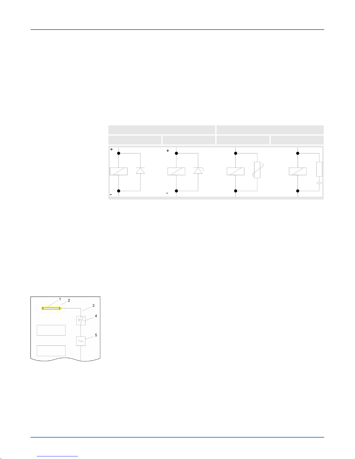
5.4 Special precautions providing high noise immunity
Inductors controlled by your programmable controller (e.g. contactors and relays) do not
normally require additional snubber networks or suppressors as the respective modules
have been provided with the required components.
Snubber networks must only be connected to inductors when output circuits can be disabled by means of additional contacts (e.g. relay contacts). In this case the integrated suppressors on the module are also disabled. Y
ou can connect diodes to suppress back-
emc, varistors or RC-networks to the inductors.
Connections of DC-activated inductors Connections of AC-activated inductors
using a diode using a Z-diode using a varistor using RC-network
Every cubicle must be provided with a power outlet for the PU. These outlets must be
wired to the distribution system, which is also used to connect the neutral conductor for
the cubicle.
The cubicle illumination should consist of incandescent lights, e.g. LINESTRA-lamps.
Avoid using fluorescent lamps as these lamps can cause interference. If you can not
avoid using fluorescent lamps you should implement the steps outlined in the following
figure.
1 Fluorescent lamp
2 Screen above the lamp
3 Screened cable
4 Switch with metallic cover
5 Line filter or screened power cable
Inductors require snubber
networks
Equipotential bonding
Power outlet for PGs
Cubicle illumination
Suppression of fluorescent lamps in cubicles
VIPA HMI
Installation guidelines
Special precautions providing high noise immunity
HB160 | PPC | 67K-RRJ0 | en | 18-30 66
Page 67
5.5 Checklist for the EMC-compliant installation of controllers
EMC-measures Space for Notes
Connection of the inactive parts
You should take special care to check the connections of:
n Module racks
n Frames
n Screen and protected earth conductor
Are all the inactive metal parts interconnected by means of large-surface and lowimpedance connections?
Has a proper connection been installed with respect to the ground/protected earth conductor system?
Has the isolation been removed from varnished and anodized surfaces or have these
connections been fitted with special contact washer?
Have the connection been protected from corrosion, e.g. by means of grease?
Have doors been grounded by means of grounding straps connected to the body of the
cubicle?
Cable routing
Cabling divided into groups?
Power cables (230 ... 400V) and signal lines installed in separate channels or
bunches?
Potential compensating
When installing the equipment at separate locations, check the installation of the
potential compensating line.
Cable screen
All covers of plugs are metallic?
All analog and data lines installed screened?
Line screens attached to the screening or the protected earth conductor?
Have the screens been connected by means of large-surface and low-impedance
cable clamps?
Cable screens grounded both-sided where possible?
Inductors
Have the coils of contactors controlled by means of contacts been connected to
snubber networks?
VIPA HMI
Installation guidelines
Checklist for the EMC-compliant installation of controllers
HB160 | PPC | 67K-RRJ0 | en | 18-30 67
Page 68

Appendix
VIPA HMI
Appendix
HB160 | PPC | 67K-RRJ0 | en | 18-30 68
Page 69

Content
A History of changes
VIPA HMI
Appendix
HB160 | PPC | 67K-RRJ0 | en | 18-30 69
Page 70

A History of changes
Rev. Changes
18-25 The manual was created.
VIPA HMI
History of changes
HB160 | PPC | 67K-RRJ0 | en | 18-30 70
 Loading...