

Page 1
Subject to change to cater f or technical progress
Manual
VIPA PC-CPU 486
Ord.-No.: VIPA HB111E
Rev. 02/32
Page 2

Lerrzeichen
Page 3

Manual VIPA PC-CPU 486 About this Manual
Subject to change to cater f or technical progress
The information contained in this manual is supplied without warranties.
Information is subject to chang e without not ice.
© Copyright 2002 VIPA, Gesellschaft für Visualisierung and Prozess-
automatisierung mbH
Ohmstraße 4, D-91074 Herzogenaurach,
Tel.: +49 (91 32) 744 -0
Fax.: +49 (91 32) 744-144
EMail: [email protected]
http://www.vipa.de
Hotline: +49 (91 32) 744-114
All rights reserved
The contents of this manual was carefully examined to ensure that it
conforms with the described hardware and software.
However, discrepancies can not be avoided. The specifications in this
manual are examined regularly and corrections will be included in
subsequent editions.
We gr at efully accept suggestions for im pr ovement .
VIPA
â
is a registered trademark of VIPA Gesellschaft für
Visualisierung and Prozessautomatisierung mbH
STEP
â
5 is a registered trademark of Siemens AG.
STEP
â
7 is a registered trademark of Siemens AG.
Any other trademarks referred to in the text are the trademarks of the
respective owner and we acknowledge their registration.
Disclaimer of
liability
Trademarks
Page 4

About this Manual Manual VIPA PC-CPU 486
Subject to change to cater f or technical progress
About this Manual
This manual describes the handling of the PC-CPU 486 and PC-CPU
486DPM with Profibus-DP master from VIPA for the S7-400 from Siemens.
The modules contain a STPC, a plug-in location for COM modules from
Hilscher and optional a DP master from VI PA.
The module is pluggable to all S7-400 m odule rails from Siem ens that have
plug-in locations with combined P- and K-Bus connection.
Chapter 1: princi pl es Check t he crui se
This introduction includes recommendations on the handling of
electrostatically sensitive modules. A short overview shows you the module
and the according deployment.
The chapter closes with the block diagram.
Chapter 2: Hardware description
This chapter describes the different versions of the PC-CPU and their
special features.
In addition to the description of the components we will describe the
deployment of the storage mediums. The chapter closes with the technical
data.
Chapter 3: BIOS / Register
This chapter contains the general structure of the system. The chapter
starts with the description of the BIOS setup, followed by the address
assignment.
The chapter closes with a description of the registers.
Chapter 4: Deployment of thePC- CPU
This chapter describes the deployment of the PC-CPU. Here you will find
information about communication possibilit ies with the periphery, the CPU
and via Profibus.
The chapter closes with the guidelines for Profibus networks.
Outline
Page 5

Manual VIPA PC-CPU 486 Content
HB111E - Rev. 02/32 i
Content
User considerations .................................................................................1
Safety information ....................................................................................2
Chapter 1 Principles..............................................................................1-1
Safety Information for the User.............................................................1-2
Overview PC-CPU 486 .........................................................................1-4
Block diagram.......................................................................................1-5
Chapter 2 Hardware description...........................................................2-1
System overview...................................................................................2-2
General.................................................................................................2-3
Properties.............................................................................................2-3
Structure...............................................................................................2-4
Components.........................................................................................2-5
Deployment of the storage mediums....................................................2-9
Technical data....................................................................................2-10
Chapter 3 BIOS / Register .....................................................................3-1
BIOS setup handling............................................................................. 3-2
Address assignment at the PC ...........................................................3-10
Register description............................................................................3-11
Chapter 4 Deployment of the PC-CPU.................................................. 4-1
Overview...............................................................................................4-2
Communication via periphery................................................................4-3
Communication via page frame............................................................4-4
Profibus communication of the PC-CPU 486DPM................................4-7
Project engineering DP master.............................................................4-9
Communication PC with DP master....................................................4-11
Communication by deploying COM modules ......................................4-15
Profibus assembly guidelines..............................................................4-16
Appendix................................................................................................A-1
Index....................................................................................................A-1
Page 6

Content Manual VIPA PC-CPU 486
ii HB111E - Rev. 02/32
Page 7
Manual VIPA PC-CPU 486 User information
HB111E - Rev. 02/32 1
User considerations
This manual describes the PC-CPU 486 for the S7-400 f rom Siemens. It
contains the construction, project implem entation and technical data.
The manual is targeted at users who have a background in automation
technology and PLC-programming.
This manual consists of 8 chapters. Every chapter provides the description
of one specific topic.
This manual provides the following guides:
• An overall table of content s at the beginning of the manual
• An overview of the topics for every chapter
• An index at the end of the m anual.
The manual is available in:
• printed for m on paper
• in electronic form as PDF-file (Adobe Acrobat Reader)
Important passages in the text are highlighted by following icons and
headings:
Danger!
Immediate or likely danger.
Personal injury is possible.
Attention!
Damages to property is likely if t hese warning s ar e not heeded.
Note!
Supplementary information and useful t ips.
Objective and
contents
Target audience
Structure of the
manual
Guide to the
document
Availability
Icons
Headings
Page 8

Index Manual VIPA PC-CPU 486
2 HB111E - Rev. 02/32
Safety information
The PC-CPU 486 is constructed and manufactur ed for:
• communication and process control
• general control and aut omation tasks
• industrial applications
• operation within the environmental conditions specif ied in the technical
data
• installation into a cubicle
Danger!
This device is not certified for applicat ions in
• explosive environments (EX-zone)
The manual must be available to all personnel in the
• project design depar tment
• installation department
• commissioning
• operation
The following conditions must be met bef ore usi ng or commi ssioning
the components described in this manual:
• Modification to the process control system should only be carried out
when the system has been disconnected from power!
• Installation and modifications only by properly trained personnel
• The national rules and regulations of the respective country must be
satisfied (installation, safety, EMC ...)
National rules and regulations apply to the disposal of t he uni t !
Application
specifications
Documentation
Disposal
Page 9

Manual VIPA PC-CPU 486 Chapter 1 Principles
HB111E - Rev. 02/32 1-1
Chapter 1 Principles
This introducing chapter contains hints about the usage of electr ostatically
sensitive modules and an overview over their deployment.
The following text describes:
• Safety Information for the user
• Block diagra m
• Overview PC-CPU 486
Topic Page
Chapter 1 Principles..............................................................................1-1
Safety Information for the User.............................................................1-2
Overview PC-CPU 486 .........................................................................1-4
Block diagram.......................................................................................1-5
Type Order number Description
PC-CPU486 VIPA 486-1BA00 32MB RAM, 8MB Flash
PC-CPU486DPM VIPA 486-1BM00 32MB RAM, 8MB Flash, DP Master
Outline
Content
Order Data
Page 10

Chapter 1 Principles Manual VIPA PC-CPU 486
1-2 HB111E - Rev. 02/32
Safety Information for the User
VIPA modules make use of highly integrated components in MOStechnology. These components are extremely sensitive to over-voltages
that may occur during electrostatic discharg es.
Electrostatically sensitive equipment!
The symbol at the left is attached to modules that can be destroyed by
electrostatic discharges.
The symbol is located on the module, the module rack or on packing
material and it indicates the presence of electrostatically sensitive
equipment.
It is possible that electrostatically sensitive equipment is destroyed by
energies and voltages that are far less than the human threshold of
perception. These voltages may occur where persons do not discharge
themselves before handling electrostatically sensitive modules and they
may damage components thereby causing the module to become
inoperable or unusable.
Modules that have been damaged by electrostatic discharge are usually
not detected immediately. The respective failure may become apparent
after a period of operat ion.
Components damaged by electrostatic discharges can fail after a
temperature change, mechanical shock or changes in the electrical load.
Only the consistent implementation of protective devices and meticulous
attention to the applicable rules and regulations for handling the respective
equipment is able to prevent failures of electrostatically sensitive modules.
Handling of
electrostatically
sensitive modules
Causes
Behavior of
damaged modules
Precautions
Page 11

Manual VIPA PC-CPU 486 Chapter 1 Principles
HB111E - Rev. 02/32 1-3
Please ship the modules exclusively in the original packing material.
Additionally you may cover the shipping-ready modules with a conductive
package. Conductive packages are anti-static foils or metallized plastic
boxes.
When you are executing measurements on electrostatically sensitive
modules you should take the following precautions:
• Floating instrum ent s m ust be discharged before use.
• Instruments must be grounded.
You should only use soldering irons with grounded tips when making
modifications on electrostatically sensitive modules.
Attention!
Personnel and instruments should be grounded when working on electrostatically sensitive modules.
Shipping of
modules
Measurements
and alterations on
electrostatically
sensitive modules
Page 12

Chapter 1 Principles Manual VIPA PC-CPU 486
1-4 HB111E - Rev. 02/32
Overview PC-CPU 486
The PC-CPU 486 is a complete compact PC-AT with the power of a 486DX processor. On the internal 8MByte Flash-ROM the operating system
MS-DOS 6.22 has been preinstalled.
Beside the plug for keyboard, m onitor resp. T FT display, t he PC-CPU 486
includes an optional Profibus master. The project engineering of the DP
master takes place via WinNCS from VIPA, the access via C-funct ions.
Further on, the PC has an internal plug-in location for Hilscher COM
modules.
For the external storage of data, the PC has an CompactFlash
-slot Type II
at the front side. Here you may plug in CompactFlash
cards resp. hard
discs like e.g. the IBM Microdrive with a storage capacity up to 1GByte.
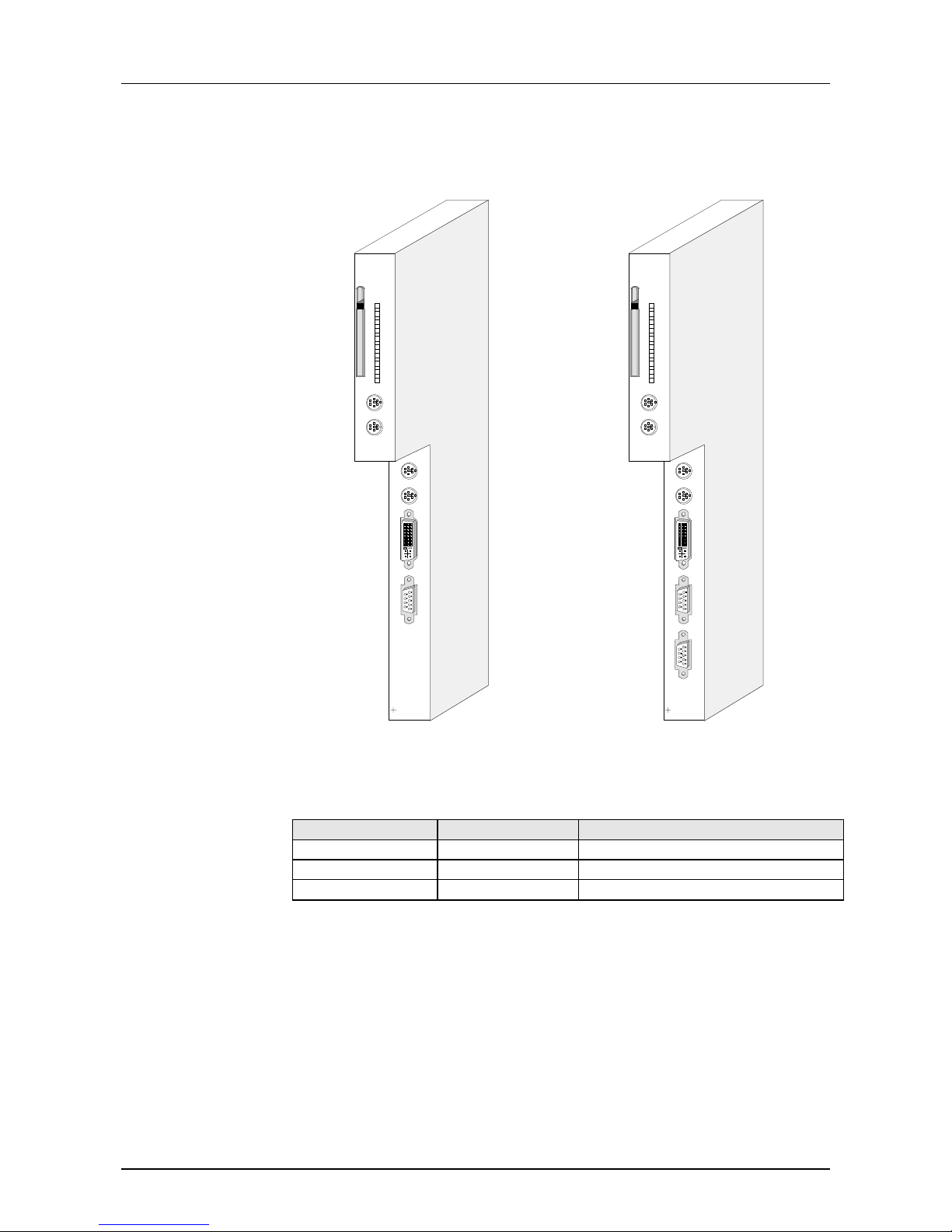
At this time the PC-CPU 486 is available in the following 2 variants:
• PC-CPU 486 (VIPA 486-1BA00)
with 32MB RAM, 8MB Flash-ROM (DiskOnChip
),
Plug-in locations for: Type II Com pactFlash
and Hilscher COM module
Connections: Mouse, keyboard, DVI jack, interface for communication
and diagnosis at deployment of a Hilscher COM module
• PC-CPU 486 DPM (VIPA 486-1BM00)
Like PC-CPU 486 additionally with integrated Prof ibus- DP m aster.
If nothing else is mentioned, the inf ormation in this manual refers to
the basic version PC-CPU 486.
There are the following possibilities for deploying the PC-CPU 486 under
Profibus:
• At deployment of the PC-CPU 486DPM, the communicat ion takes place
via a Dualport-RAM. The project engineering is by means of WinNCS
from VIPA and the access at PC side via C-funct ions.
The DP master allows you to connect up to 125 Profibus-DP slaves to
the PC. The master communicates with the slaves and provides the
data for the PC via the Dualport-RAM. During this operation there may
occur a maximum of 1024Byte data for in- and out put.
• You deploy the PC-CPU 486 with a Profibus plug-in card at the COM
module plug-in location. Then access and the project eng ineering takes
place via the software added to the card.
• Operating temperature: 0... +55°C
• Storage temperature: -20... +65°C
• Relative humidity: 95% short time, 55% average, without condensation
• fan-less operat ion
General
Device variants
Deployment under
Profibus
Environmental
conditions
Page 13
Manual VIPA PC-CPU 486 Chapter 1 Principles
HB111E - Rev. 02/32 1-5
Block diagram
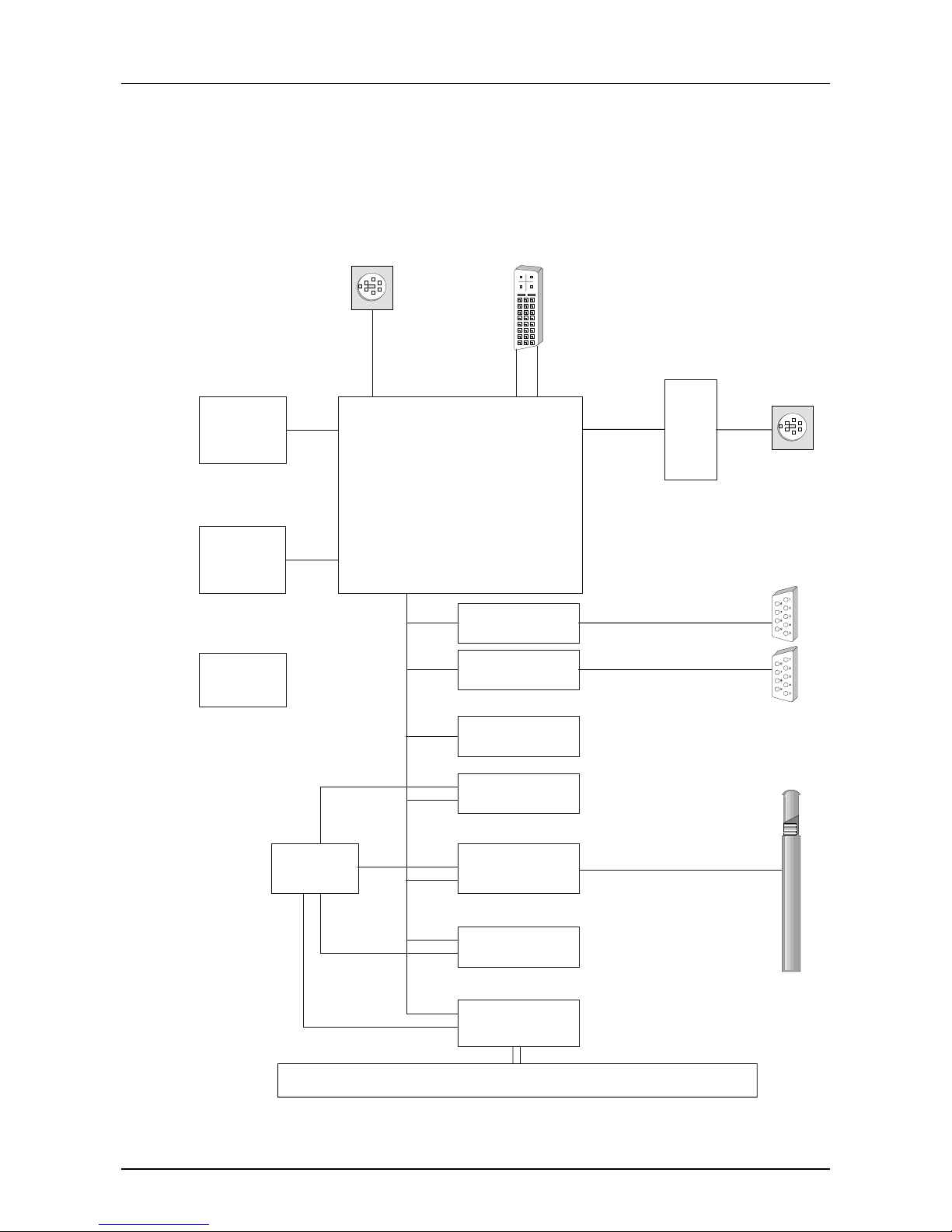
The following block diagram shows the principle construction of the PC.
DiskOnChip
8MB Flash
BIOS
DVI-Connector
MiniDin
DRAM
32MB
Power
supply
FPGA
FlashDisk
PBUS
RTC
Compact
Flash
256K Flash
COM 1
S7-400
RS
232
MiniDin
Compact
Flash
TYPE II
Keyboard
VGA
TFT
ISA-Bus
STPC
Watchdog
Reset
COM 2
Hilscher Fieldbus
module (optional)
VIPA Profibus
master (optional)
Page 14

Chapter 1 Principles Manual VIPA PC-CPU 486
1-6 HB111E - Rev. 02/32
Page 15

Manual VIPA PC-CPU 486 Chapter 2 Hardware description
HB111E- Rev. 02/32 2-1
Chapter 2 Hardware description
The PC is available in different variants described in t his chapt er.
Here you will also find information about t he usag e of the stor age medium s
DiskOnChip
and CompactFlash.
The chapter closes with the technical data.
The following text describes:
• Structure
• Components of t he PC
• Deployment of stor age mediums
• Technical data
Topic Page
Chapter 2 Hardware description...........................................................2-1
System overview...................................................................................2-2
General.................................................................................................2-3
Properties.............................................................................................2-3
Structure...............................................................................................2-4
Components.........................................................................................2-5
Deployment of the storage mediums....................................................2-9
Technical data....................................................................................2-10
Outline
Content
Page 16
Chapter 2 Hardware description Manual VIPA PC-CPU 486
2-2 HB111E - Rev. 02/32
System overview
X 2
3
4
VIPA 486-1BA00
X 2
3
4
VIPA 486-1BM00
VIPA 486-1BA00 VIPA 486-1BM00
Type Order number Description
PC-CPU 486 VIPA 486-1BA00 32MB RAM, 8MB Flash
PC-CPU 486 DPM VIPA 486-1BM00 32MB RAM, 8MB Flash, DP Master
CompactFlash
VIPA 950-1KS00
CompactFlash
Typ II, 32 MByte
Order data
Page 17

Manual VIPA PC-CPU 486 Chapter 2 Hardware description
HB111E- Rev. 02/32 2-3
General
The PC-CPU 486 is meant for the deployment in t he S7-400 f rom Siemens
and is included to your system via the STEP
®
7 manager from Siemens. For
periphery and CPU communication an ANSI-C library is in the
consignment.
For storing the operating system the PC provides an bootable DiskOnChip
®
disk drive (DOC). The Flash-based disk drive has a size of 8MB. The
deployment of the disk drive and the booting sequence is to fix at the
BIOS.
For the external storage of projects with greater data amount there is a
plug-in location at the frontside for CompactFlash
®
storage modules
Type II. Only the PC has access rights to the storage modules.
CompactFlash
®
storage modules are available at VIPA.
For the flexible connection to fieldbus systems the PC provides an internal
plug-in location for COM modules from the Hilscher company.
At the PC you will also find fieldbus, diagnosis jacks and LEDs, that are
automatically controlled by the COM module.
At deployment of a PC-CPU 486DPM is a DP master integrated. The
communication between PC and DP master happens via Dualport-RAM.
You configure the DP master via W inNCS from VIPA and access it from
the PC via C-functions.
Properties
• PC-AT compatible STPC ATLAS 133MHz with 32MB main memory
• 8MB DiskOnChip
â
, CompactFlashâplug-in location, both bootable
• 2 RS232 interfaces and MiniDin jack for keyboard
• DVI jack (Digital Visual Interf ace) for TFT-LCD via PANEL LINK
â
• integrated Watchdog t im er
• Project eng ineer ing of the optional DP master via WinNCS from VIPA
• Standard page frame interface (4 page frames)
• CPU function, AIO, DIO via ANSI-C library
Application area
DiskOnChip
®
for
configuration data
CompactFlash
®
Plug-in location
for Hilscher
COM modules
DP master in the
PC-CPU 486DPM
Page 18
Chapter 2 Hardware description Manual VIPA PC-CPU 486
2-4 HB111E - Rev. 02/32
Structure
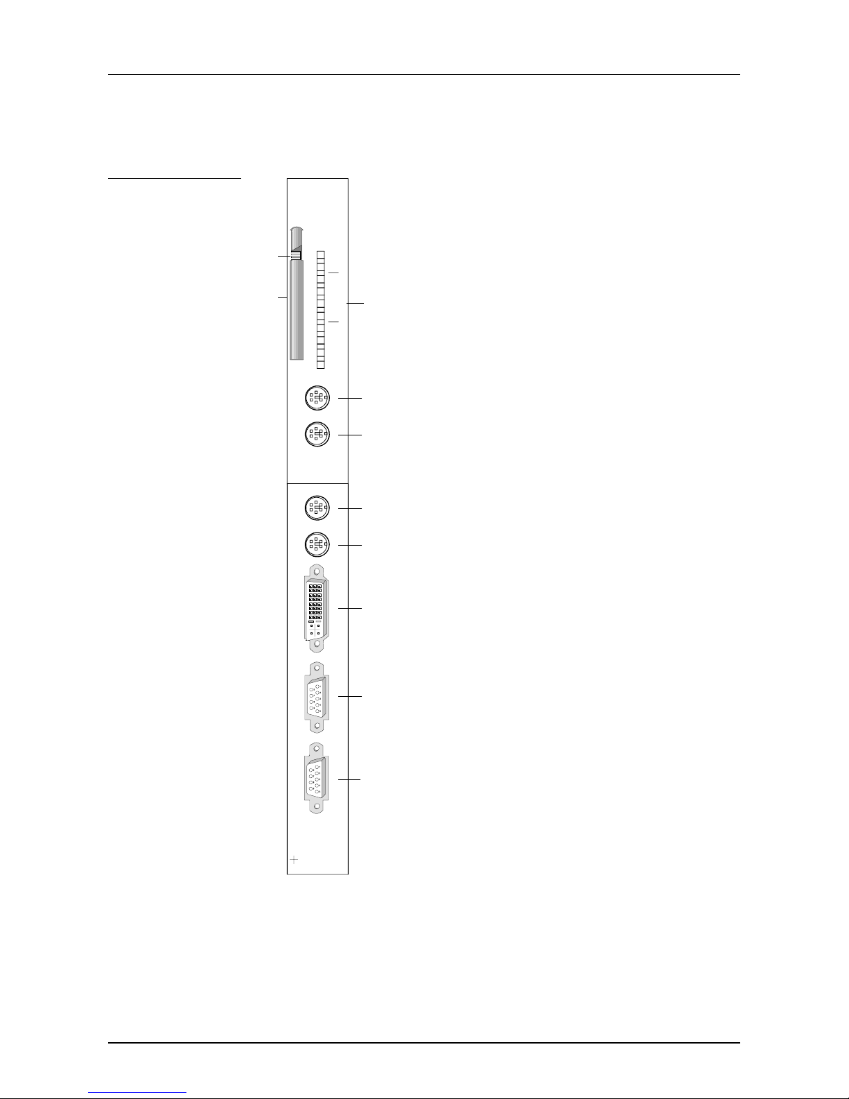
2
1
X
2
34
VIPA 486-1BM00
3
4
5
6
7
8
9
10
D
P
C
O
M
P
B
D
V
I
C
O
M
1
C
O
M
2
D
T
PC-RN
PC-ST
DP-DE
DP-RN
DP-ER
DP-IF
F-RN
F-RD
F-ER
F-S
[1]
[2]
[3]
[4]
[5]
[6]
[7]
[8]
[9]
[10]
Exit key for CompactFlash
â
Plug-in location for CompactFlash
â
LEDs status monitor
RS232 diagnosis interface for COM module
Keyboard
COM 1 (RS232)
COM 2 (RS232)
DVI interface
Jack for the optional COM module
RS485 jack for Profibus DP master
(only VIPA 486-1BM00)
Structure
PC-CPU 486DPM
Page 19
Manual VIPA PC-CPU 486 Chapter 2 Hardware description
HB111E- Rev. 02/32 2-5
Components
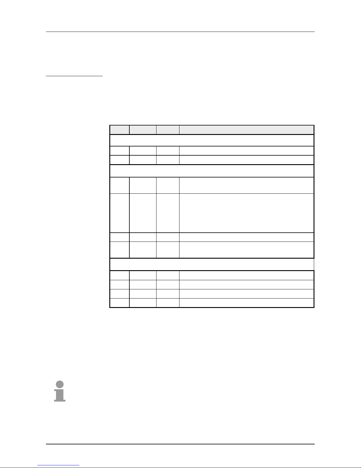
At the frontside of the PC there are different LEDs serving the program
status monitoring. The usage and the according colors of these diagnostic
LEDs are to find in the following table.
Pos. Label Color Description
PC
1 PC-RN green PC is in RUN
2 PC-ST red PC is in STOP
Profibus DP master
3 DP-DE yellow DE (Data exchange) shows communication via
Profibus.
4 DP-RN green If only DP-RN is on, the DP master is in RUN.
The slaves are called and the outputs are 0
("clear" state).
With DP-RN+DP-DE on, the master is in
"operate" state. It changes data with the slaves.
5 DP-ER red Flashes at slave failure (Error)
6 DP-IF red Profibus DP master is signalizing an initiali-
zation error at wrong parameterization.
COM module
7 F-RN green COM module is in RUN
8 F-RD green COM module shows READY
9 F-ER red COM module shows error
10 F-S yellow COM module shows status
At this plug-in location you may insert a CompactFlashâ memory card Type
I+II. The PC includes the card as hard disk in the system. The deployment
of a CompactFlash
â
card has to be set in the BIOS.
Together with a CompactFlash
â
adapter the memory card gets compatible
to the "big" PCMCIA Type II form at. Thus you may exchange data with all
PCs via the PCMCIA slot.
Note!
The memory card may only be plugged in resp. out when the Pchas been
shut down!
PC-CPU 486
LEDs
Plug-in location
for
CompactFlash
ââââ
Page 20
Chapter 2 Hardware description Manual VIPA PC-CPU 486
2-6 HB111E - Rev. 02/32
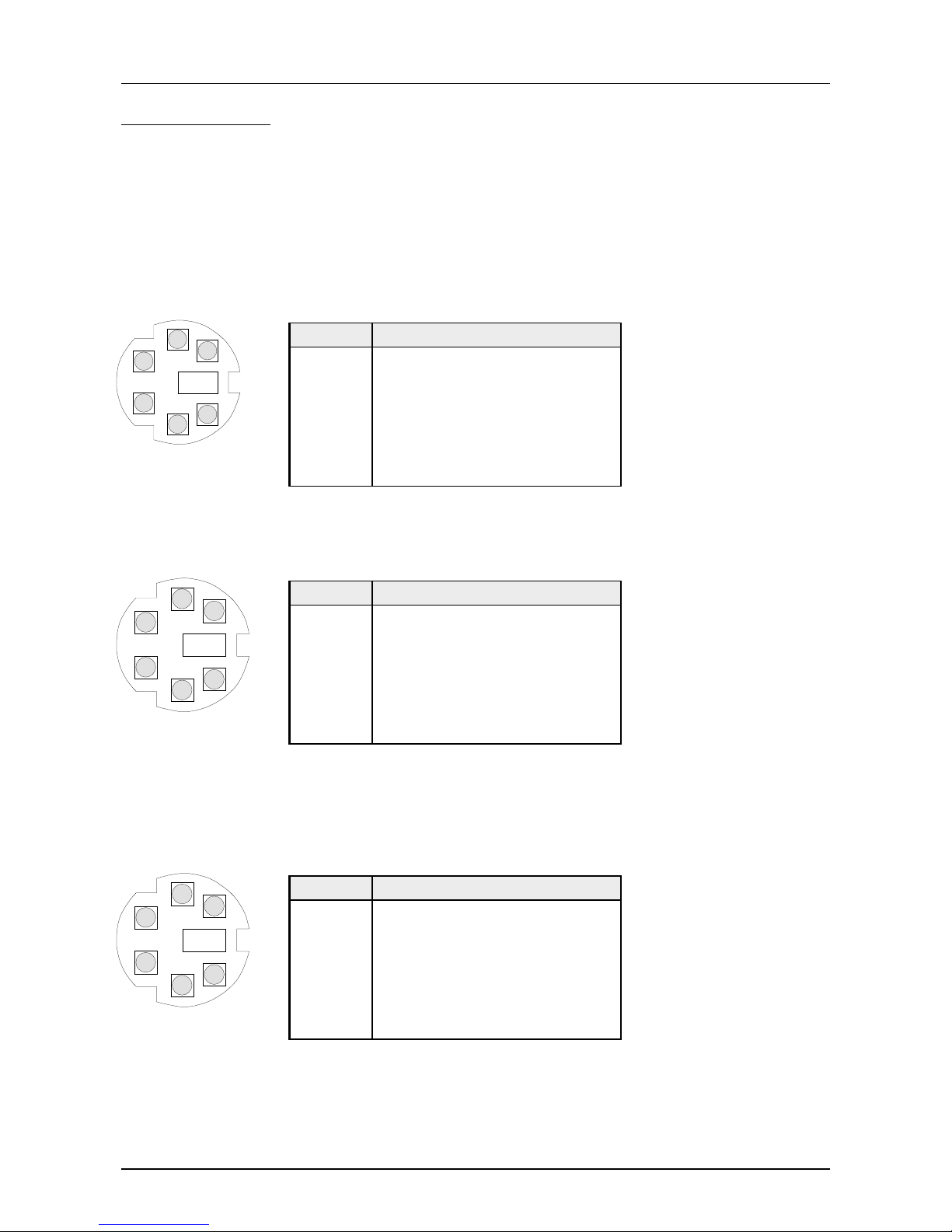
Diagnostic interface (RS232) for COM module.
This jack is used for diagnostic purposes at deployment of a COM module.
More information about this diagnostic interface is to find in the
documentation of Hilscher.
MiniDin jack
Pin Assignment
1DTR
2RXD
3GND
4CTS
5RTS
6TXD
Please connect your keyboard here!
MiniDin jack
Pin Assignment
1 + KB-Data (I/O)
2reserved
3GND
4+5V
5 + KB-Clock (I/O)
6reserved
The slot of the serial interface (RS232) is called as COM 1 / COM 2 and is
defined for data transfers over maximum 15m at up to 38,4kBaud. The
communication takes place via data, message and control lines.
MiniDin jack
Pin Assignment
1n.c.
2RXD
3GND
4CTS
5RTS
6TXD
Jacks and plugs
Diagnosis
1
2
4
3
6
5
Keyboard
1
2
4
3
6
5
Serial interface
COM 1 / COM 2
1
2
4
3
6
5
Page 21
Manual VIPA PC-CPU 486 Chapter 2 Hardware description
HB111E- Rev. 02/32 2-7
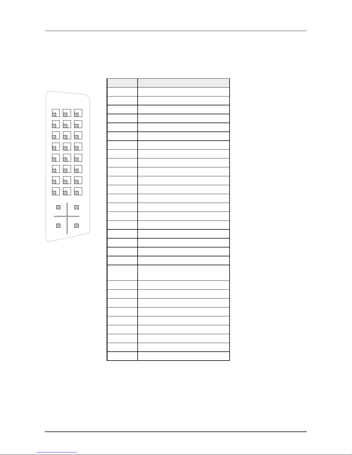
The DVI jack (Digital Visual I nterface) provides the connection of analoge
and digital displays or monitors with a max. resolution of 1280 x 1024 Pixel.
The interface has the f ollowing pin assig nm ent:
Pin Signal
C1 Analog Red
C2 Analog Green
C3 Analog Blue
C4 Analog Horizontal Sync
C5 Analog RGB Return
1 T.M.D.S Data22 T.M.D.S Data2+
3 T.M.D.S Data2/4 Shield
4 T.M.D.S Data45 T.M.D.S Data46 DDC Clock
7 DDC Data
8 Analog Vertical Sync
9 T.M.D.S Data110 T.M.D.S Data1+
11 T.M.D.S Data1/3 Shield
12 T.M.D.S Data313 T.M.D.S Data3+
14 +5V Power
15 Ground (return for +5V, HSync
and VSync)
16 Hot Plug Detect
17 T.M.D.S Data018 T.M.D.S Data0+
19 T.M.D.S Data0/5 Shield
20 T.M.D.S Data521 T.M.D.S Data5+
22 T.M.D.S Clock Shield
23 T.M.D.S Clock+
24 T.M.D.S Clock-
DVI interface
1
2
3
4
5
6
8
17
18
19
20
21
22
23
24
C1
C2
C3
C4
9
16
C5
Page 22
Chapter 2 Hardware description Manual VIPA PC-CPU 486
2-8 HB111E - Rev. 02/32
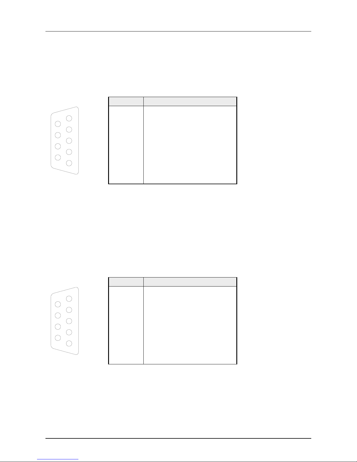
This slot receives the signals of the opt ional COM module.
The pin assignment of the int er face is shown in the following picture:
More detailed information for t he deployment of the COM module is to find
in the documentation from Hilscher.
9pin jack
Pin Assignment
1 Screen
2n.c.
3L2P
4 CNTR-P
5GND
65V
7n.c.
8L2N
9n.c.
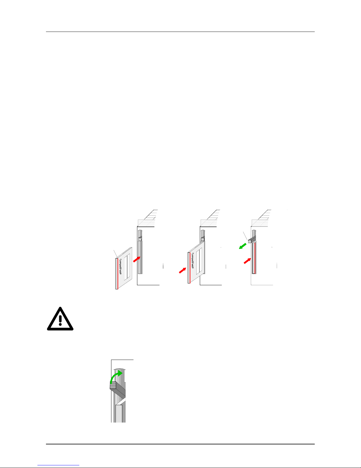
The module plugged in here is a Profibus-FMS master module from
Hilscher.
Via this interface you include the DP master of the PC-CPU 486DPM into
your Profibus system.
The pin assignment of the int er face is shown in the following picture:
9pin jack:
Pin Assignment
1GND
2 MODE-PIN
3 RxD/TxD-P
4 CNTR-P
5GND
6 5V (max. 70mA)
7n.c.
8 RxD/TxD-N
9n.c.
COM-PB
RS485 interface
5
4
3
2
1
9
8
7
6
5
4
3
2
1
9
8
7
6
Page 23
Manual VIPA PC-CPU 486 Chapter 2 Hardware description
HB111E- Rev. 02/32 2-9
Deployment of the storage mediums
The PC has an included hard disk on basis of Flash-ROM with a size of
8MB DiskOnChip
and a CompactFlash-Slot Type II.
Via a CompactFlash
adapter the CompactFlash card gets compatible to
the "big" PCMCIA Type II format. This enables the data exchange with PCs
with PCMCIA slot.
The assignment of the hard disks takes place via the BIOS-SETUP
program.
Here you have different possibilities to contr ol t he boot behavior of the PC.
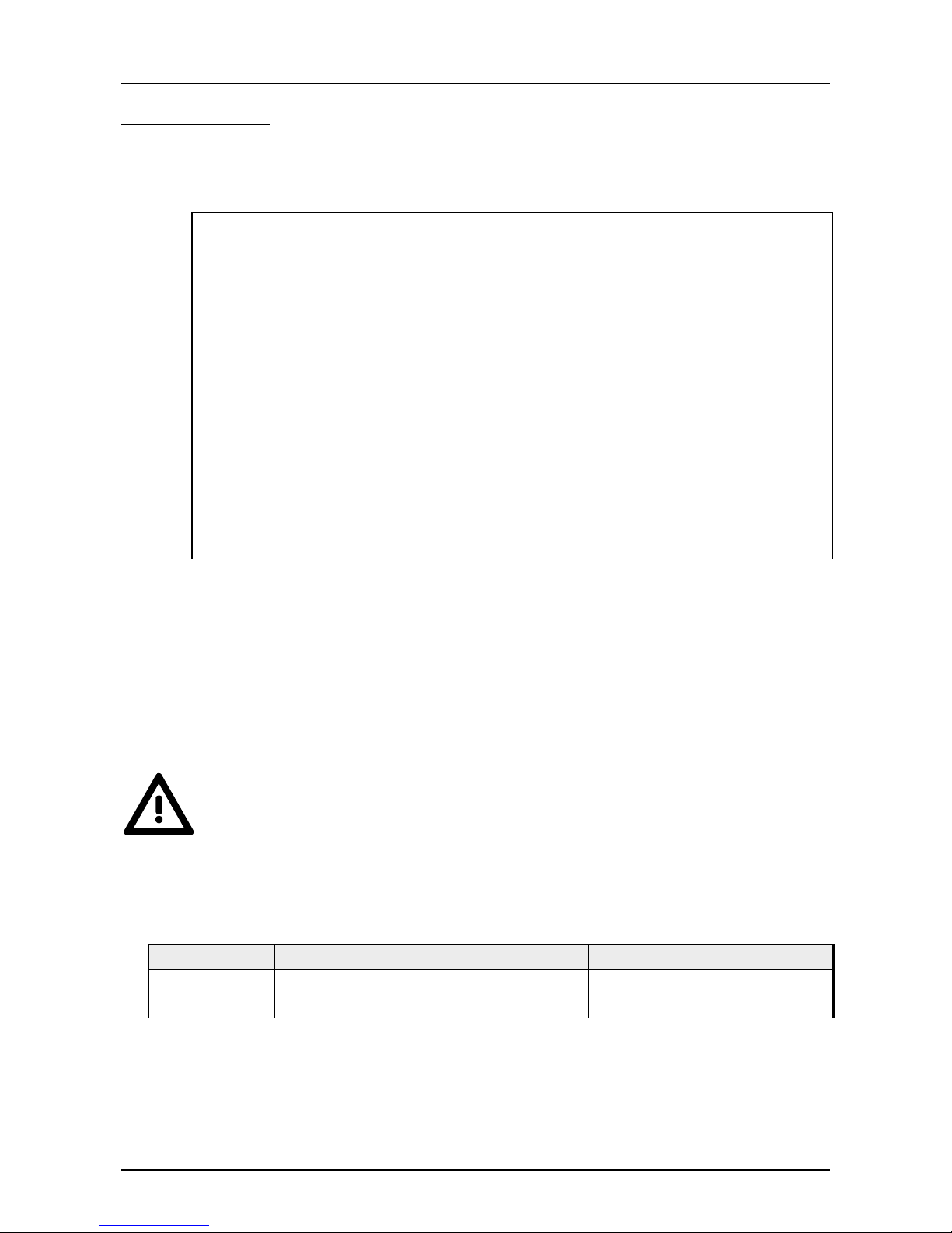
Every CompactFlash
storage module has an eject edge [1]. Turn the
module so that the eject edge shows to the right .
Push the storage module into the PC without too much pressure until it
clicks and the eject lever [2] appears.
To remove the CompactFlash
card push the eject lever.
PC 288
C
O
M
1
ON
PW
RN
BA
M
E
M
O
R
Y
[1]
PC 288
C
O
M
1
ON
PW
RN
BA
M
E
M
O
R
Y
M
E
M
O
R
Y
[2]
Note!
The CompactFlash
â
storage module may only be inserted or removed
when shut down!
You have to set the storage module in the BIOS setup!
M
E
For protecting from unwanted ejects of the CompactFlash
â
card you may fold the eject lever into the upper side of the
case.
For a wanted eject you either fold the eject lever back or you
operate it with a screwdriver.
Outline
CompactFlash
insert/eject
Unwanted eject
protection
Page 24

Chapter 2 Hardware description Manual VIPA PC-CPU 486
2-10 HB111E - Rev. 02/32
Technical data
General VIPA 486-1BA00
CPU STPC ATLAS 133MHz
Memory 32MB work memory
Storage medium
8MB DiskOnChip
â
CompactFlashâ slot Type II
Watchdog integrated and to trigger via registers
Profibus functionality via optional COM module from Hilscher
Electrical data
Voltage supply DC 5V via backplane bus
Current consumption max. 1.3A
Dissipation power typ. 6.5W
Status monitors via LEDs at the front side for the single components
Connections / interfaces MiniDin Diagnosis for COM module (RS232)
MiniDin Keyboard
MiniDin COM 1 (RS232)
MiniDin COM 2 (RS232)
9pin Fieldbus connection for COM module
DVI Interface for monitor/TFT
CompactFlash
â
slot, Type II
Buffer clock and CMOS Lithium-Akku, 30 days buffer
Dimensions and Weig ht
Dimensions (WxHxD) in mm 25x290x210
Weight ca. 750g
• Operating temperature: 0 ... +55°C
• Storage temperature: -20 ... +65°C
• Relative humidity: short-timed 95% (average 55%), without
condensation
• fan-less operat ion
PC-CPU 486
Environmental
conditions
Page 25

Manual VIPA PC-CPU 486 Chapter 2 Hardware description
HB111E- Rev. 02/32 2-11
General VIPA 486-1BM00
CPU STPC ATLAS 133MHz
Memory 32MB work memory
Storage medium
8MB DiskOnChip
â
CompactFlashâ slot Type II
Watchdog integrated and to trigger via registers
Profibus functionality DP master integrates more fieldbus functions via
optional COM module from Hilscher
Electrical data
Voltage supply DC 5V via backplane bus
Current consumption max. 1.3A
Dissipation power typ. 6.5W
Status monitors via LEDs at the front side for the single components
Connections / interfaces MiniDin Diagnosis for COM module (RS232)
MiniDin Keyboard
MiniDin COM 1 (RS232)
MiniDin COM 2 (RS232)
9pin Fieldbus connection for COM module
9pin Profibus connection for DP master
DVI Interface for monitor/TFT
CompactFlash
â
slot, Type II
Buffer clock and CMOS Lithium-Akku, 30 days buffer
Dimensions and Weig ht
Dimensions (WxHxD) in mm 25x290x210
Weight ca. 750g
• Operating temperature: 0 ... +55°C
• Storage temperature: -20 ... +65°C
• Relative humidity: short-timed 95% (average 55%), without
condensation
• fan-less operat ion
PC-CPU 486DPM
Environmental
conditions
Page 26

Chapter 2 Hardware description Manual VIPA PC-CPU 486
2-12 HB111E - Rev. 02/32
Page 27

Manual VIPA PC-CPU 486 Chapter 3 BIOS / Register
HB111E - Rev. 02/32 3-1
Chapter 3 BIOS / Register
Content of this chapter is the description of the BIOS setup and the
registers. Via the BIOS setup you may configure the hardware of your PC
and adjust it to your conditions.
By accessing the registers you may directly influence your PC.
The following text describes:
• BIOS setup
• Register assignm ent
Topic Page
Chapter 3 BIOS / Register .....................................................................3-1
BIOS setup handling............................................................................. 3-2
Address assignment at the PC ...........................................................3-10
Register description............................................................................3-11
Outline
Content
Page 28

Chapter 3 BIOS / Register Manual VIPA PC-CPU 486
3-2 HB111E - Rev. 02/32
BIOS setup handling
At the start-up of the system, the BIOS version is displayed on the
connected monitor. Then the BIOS executes a test of the system
components and the memory. At the end of the test the system att empts t o
boot. Between the start-up and the boot procedure you may access the
BIOS setup routine by operating the [Entf]/[Del] key.
An appropriate message is displayed on the screen.
Via the setup menu you may configure the hardware of your PC.
After hitting the [Entf]/[Del] key, the following menu appears:
+------------------------------------------------------------------------------+
| System Bios Setup - Utility v4.2 |
| (C) 1999 General Software, Inc. All rights reserved |
+------------------------------------------------------------------------------+
| |
| |
| |
| |
| Basic CMOS Configuration |
| VIPA Configuration |
| Read Setup values from CMOS |
| Reset CMOS/Flash to factory defaults |
| Write to CMOS/Flash and Exit |
| Exit without changing CMOS/Flash |
| |
| |
| |
| |
| |
| |
+------------------------------------------------------------------------------+
| <Esc> to continue (no save) |
| |
+------------------------------------------------------------------------------+
With the help of t he standard cursor keys you may select the single menu
options. You activate the selected sub-menu with [Enter].
Via [ESC] you leave the setup without saving your entries.
General
BIOS menu
Page 29

Manual VIPA PC-CPU 486 Chapter 3 BIOS / Register
HB111E - Rev. 02/32 3-3
Every dialog box that is accessible via the main menu is controlled by
means of the following keys:
[ESC] key
With the [ESC
] key the dialog window is closed and you return to the main
menu. The altered parameters ar e st or ed but not written to the CMOS.
Cursor keys
With the Curs or keys you choose the parameter you want to modify.
[PU]/[PD]
With the keys
[PgUp] and [PgDn] or [Bild↑] and [ Bild↓] or at the numeric
block [+] and [-] you may alter the value of a par am eter.
Note!
Please regard, that at the setup level there has not been loaded a driver for
the German keyboard yet. Modified setup values are only valid and written
into CMOS by confirming your changes explicitly with "Y". To obtain Y, you
have to push the [Z] key.
Control keys in
BIOS
Page 30
Chapter 3 BIOS / Register Manual VIPA PC-CPU 486
3-4 HB111E - Rev. 02/32
This sub-menu provides access to the main settings f or your system.
The menu is divided into a number of logical units. You may navigate
through these by means of the cursor keys.
+------------------------------------------------------------------------------+
| |
| System Bios Setup - Basic CMOS Configuration |
| (C) 1999 General Software, Inc. All rights reserved |
+---------------------------+--------------------+-----------------------------+
| DRIVE ASSIGNMENT ORDER: | Date:>Jan 01, 2000 | Typematic Delay : 250 ms |
| Drive A: (None) | Time: 10 : 03 : 25 | Typematic Rate : 30 cps |
| Drive B: (None) | NumLock: Disabled | Seek at Boot : None |
| Drive C: CompactFlash +--------------------+ Show "Hit Del" : Enabled |
| Drive D: (None) | BOOT ORDER: | Config Box : Enabled |
| Drive E: (None) | Boot 1st: Drive C: | F1 Error Wait : Enabled |
| Drive F: (None) | Boot 2nd: (None) | Parity Checking : (Unused) |
| Drive G: (None) | Boot 3rd: (None) | Memory Test Tick : Enabled |
| Drive H: (None) | Boot 4th: (None) | Test Above 1 MB : Disabled |
| Drive I: (None) | Boot 5th: (None) | Long Memory Test : (Unused) |
| Drive J: (None) | Boot 6th: (None) | Hexadecimal Case : Upper |
| Drive K: (None) +--------------------+-----------------+-----------+
| Boot Method: Boot Sector | IDE DRIVE GEOMETRY: Sect Hds Cyls | Memory |
+---------------------------+ Ide 0: 2 = AUTOCONFIG, PHYSICAL | Base: |
| FLOPPY DRIVE TYPES: | Ide 1: Not installed | 640KB |
| Floppy 0: Not installed | Ide 2: Not installed | Ext: |
| Floppy 1: Not installed | Ide 3: Not installed | 30MB |
+---------------------------+--------------------------------------+-----------+
| U/D/L/R/<CR>/<Tab> to select |
| or <PgUp>/<PgDn>/+/+ to modfiy |
+------------------------------------------------------------------------------+
This section is used to assign logical drive names to the physical drives.
The VIPA BIOS only provides support for dr ive "C".
The following settings are valid for " C" :
• "None": if you did not insert a CompactFlash
card
• "CompactFlash": if you have installed a CompactFlash card.
Note!
All the other drives must be assigned to type "None". Any other setting can
cause malfunction of the PC.
Please also note that the settings for "Ide 0" in the section IDE Drive
Geometry must be changed at the same time as the parameters f or drive
"C". The following settings ar e valid:
CompactFlash
DRIVE ASSIGNMENT ORDER \ Drive C: IDE DRIVE GEOMETRY \ Ide0:
Installed
CompactFlash
2 = AUTOCONFIG, PHYSICAL
Not installed None Not installed
The integrated DiskOnChip drive (DOC) is configured by means of the
"VIPA Configuration" menu.
Basic CMOS
Configuration
Drive Assignment
Order and
IDE Drive Geome try
Page 31

Manual VIPA PC-CPU 486 Chapter 3 BIOS / Register
HB111E - Rev. 02/32 3-5
Here you would normally define the settings for the floppy disk drive. Since
the PC does not support floppy disk drives you have to select the type "Not
installed"! Otherwise you will encounter long-term delays between the
system test and the start-up of the system.
Here you enter the current date and time.
The "NumLock" parameter defines the status of the [NumLock] key after
the system has booted.
Note!
If the real-time clock has stopped it has to be assumed that the backup
battery for the CMOS memory is discharged or defective.
Please contact the VIPA Hotline if this battery has still not accepted a
charge after one day.
Your CMOS settings are safe even if the battery is empty. You only need to
adjust the clock and the date.
This parameter is preset to "Drive C" and it defines the boot sequence.
This section defines the geometry settings of the IDE drives.
If you are using a CompactFlash
card you have to enter "autoconfig,
physical" for this parameter. I f you did not inst all a Compact Flash
card the
parameter must be set to "None".
This parameter defines the keyboard interf ace and specifies the repetition
rate for the characters. You should not change this setting.
This option specifies which drives should receive a "SEEK" command
before booting the system. T he default is "NONE" to ensure that the boot
procedure is as quick as possible.
If this option is active the system will display a message to press [Del] to
access the setup menu while the system is booting.
This parameter specifies whether the configuration settings should be
displayed on screen when the system boots.
Floppy drive types
Date, Time,
NumLock
Boot order
IDE Drive
Geometry
Typematic
Rate/Delay
Seek at Boot
Show "Hit Del"
Config Box
Page 32

Chapter 3 BIOS / Register Manual VIPA PC-CPU 486
3-6 HB111E - Rev. 02/32
If you activate this menu item, the boot process is st opped when an error is
detected. You then may decide what action to take. If you press [F1] the
system will continue booting. Press [Del] to gain access to t he set up menu.
This menu item is not used.
Turn this option on to sound a test click via the PCs speak er when mem ory
is being tested.
This parameter determines whether the memory above the 1MB limit will
be tested by the memory test or not.
This menu item is not used.
This menu item determines the display format that the BIOS uses for
hexadecimal numbers. You can either choose "UPPER" (capitals) or
"LOWER" (lower case).
This menu item displays the memory configuration below 1MB (Base
Memory) and above 1MB (Extended memory). These parameters are
purely for information purposes and they cannot be changed.
F1 Error Wait
Parity Checking
Memory Test Tick
Test Above 1MB
Long Memory Test
Hexadecimal Case
Memory Base /
Ext.
Page 33

Manual VIPA PC-CPU 486 Chapter 3 BIOS / Register
HB111E - Rev. 02/32 3-7
This sub-menu is used to define the board-specific settings. You may
navigate through the menu by means of t he cur sor keys.
+------------------------------------------------------------------------------+
| System BIOS Setup - VIPA Configuration |
| (C) 1999 General Software, Inc. All rights reserved |
+---------------------------------------+--------------------------------------+
| VGA Frame Buffer Size : 1.0 Mb |VGA Palette Snoop : Enabled |
| Graphic Clock Speed : 85 MHz |Watchdog : Enabled |
| Drive C : CF |CPU Mode : Enabled |
| L1 Cache : Enabled | |
| | |
| | |
| | |
| | |
| | |
| | |
| Bios Version: 1.0.0 | |
| Serial number: 040002 | |
| Release: 1 | |
| FPGA Version: 10 | |
| | |
| | |
+---------------------------------------+--------------------------------------+
| U/D/L/R/<CR>/<Tab> to select |
| or <PgUp>/<PgDn>/+/+ to modify |
+------------------------------------------------------------------------------+
This parameter determines the amount of memory that is used as g raphic
memory for the internal graphic controller.
The respective memory area is no longer available as ma in m emory f or the
processor.
This option determines the clock speed used for the internal graphic
controller. This option should always be set to "85MHz".
This parameters determines the dr ive from which the operating system is
booted:
"CF" CompactFlash
(C:) followed by the internal drive (D:)
"DOC" DiskOnChip
- internal drive (C:) followed by CompactFlash
(D:)
In every case the other drive will be accessible as drive D:.
This option enables and disables the L1 cache of the processor.
This menu item determines whether access to the VGA palette can only
occur within the STPC (disabled) or whether it should also be routed to t he
external PCI bus (enabled).
VIPA
Configuration
VGA Frame
Buffer Size
Graphic Clock
Speed
Drive C
L1 Cache
VGA Palette
Snoop
Page 34

Chapter 3 BIOS / Register Manual VIPA PC-CPU 486
3-8 HB111E - Rev. 02/32
This option is used to enable or disable a Watchdog that issues an
automatic reset after a cer t ain t im e has elapsed ( 30s).
If you deactivate the W atchdog in your application pr ogr am you can ensure
that your system has booted without errors. Otherwise the PC is re-booted
when the watchdog has expired.
You may define the watchdog time and the watchdog properties in the
system register.
This parameter determines the physical properties of the P bus to the S7400 bus from Siemens. You may select fr om :
enable: Operation as stand-alone CPU in the PLC
(allows the direct communication with the peripheral area
without PLC-CPU)
disable: Operation as CP in the PLC
(allows page frame communication with a Siemens-CPU)
The left hand section of t he "VIPA Configuration" menu displays hardware
specific parameters:
BIOS-Version: The version level of the BIOS
Serial No.: Every PC is provided with a unique serial no. This serial
no. is identical to the serial no. located on the enclosure.
Revision level: identical to the revision level located on the enclosure.
FPGA-Version: The version of the FPGA that controls the V-Bus access.
Note!
You should include this information when you request information from t he
service department of VIPA GmbH, to allow us to help you more effectively.
Watchdog
CPU Mode
Version data
Page 35

Manual VIPA PC-CPU 486 Chapter 3 BIOS / Register
HB111E - Rev. 02/32 3-9
Note!
The following menu items display a query that is to be answered with "Yes"
or "No".
Please note that the keyboard uses the US layout for the BI OS setup, i.e.
that you have to press the [Z] key on German keyboards to obtain the letter
"Y".
This option loads the most recent settings that were saved to CMOS
memory.
This option loads the factory def ault values into CMOS memory.
If you wish to write these values into the CMOS memory you have to use
the menu item "Write to CMOS and Exit" to quit from this function.
This menu item saves the modified settings to CMOS-RAM.
When the sett ings have been saved the system is re-started automatically
which will reload the modified configuration sett ings.
Note!
This process can require a few seconds since the data is also saved in the
EEPROM.
During this time you may NOT turn the system off or issue a manual reset!
When you select this menu item, you quit from the setup menu without
saving and activating any settings to CMOS memory or to the EEPROM.
Read Setup
values from
CMOS
Reset
CMOS/Flash to
factory defaults
Write to
CMOS/Flash and
Exit
Exit without
changing
CMOS/Flash
Page 36

Chapter 3 BIOS / Register Manual VIPA PC-CPU 486
3-10 HB111E - Rev. 02/32
Address assignment at the PC
As host controller a STPC is deployed. The address range of t he RAM has
a size of 8KByte and is stored from CC000h to CDFFFh in the memory
area.
The interface administers the addr esses SA0 t o SA12.
The registers are stored in the I/O area from 298h to 29Fh.
CC000h
CDFFFh
CFFFFh
PC Address range
0000h
0800h
0400h
0C00h
1000h
1FFFh
Page frame 0
Basis+Offset
reserved
reserved
Page frame 1
Page frame 3
Page frame 2
Page 37

Manual VIPA PC-CPU 486 Chapter 3 BIOS / Register
HB111E - Rev. 02/32 3-11
Register description
The following addresses are occupied by VIPA:
CPU side
270h - 277h Watchdog
280h - 28Fh Control register I
280h - 281h reserved
282h LED Control
Bit 0 = "0" RUN LED off, "1" RUN LED on
Bit 1 = "0" STOP LED off, "1" STOP LED on
283h - 284h reserved
285h EEPROM Port
286h - 28Dh reserved
28Eh Version
28Fh Device ID = 88h
290h - 297h Control register II
290h Watchdog t im er value
291h reserved
292h C165 Control register
293h Enable register for Watchdog timer value
294h - 295h reserved
296h CPU Control
297h CPU Mode
298h - 29Fh Register for page frame communication
298h Operation mode (read/write)
299h Status register (control)
29Ah 3FD - Interrupt register (IRQ Req/Ack)
29Bh 3FF - Interrupt register (IRQ Req/Ack)
29Ch Page fr am e base r egister (read/write)
29Dh Page fr am e select register (read only)
29Eh Revision ID register (read only)
29Fh Device ID regist er ( read only)
Address range
Page 38

Chapter 3 BIOS / Register Manual VIPA PC-CPU 486
3-12 HB111E - Rev. 02/32
(I/O address range 270h-277h)
The Watchdog is t urned of f when the system has start ed or has been reset
and it can be enabled under software control.
The Watchdog reg ister is controlled via I/O address 270h and the f ollowing
parameters:
Watchdog on load 40h after address 270h
Watchdog off load 50h after address 270h
Watchdog t r igger load 60h after address 270h
and then
load 70h after address 270h
The Watchdog must be triggered when the power has been turned on. The
triggering time is programmable:
Parameter for triggering time I/O-register 290h R/W (enabled via 293h).
The trigger time is a multiple of 147ms and has to be entered in the
register 290h Watchdog time. As soon as you load the register 290h with
00h, the Wat chdog timer is deactivated.
Please regard, that you have to enable write access for the register
Watchdog time.
The following sequences to the register 293h are activating resp.
deactivating the write access to the registers 290h and 292h.
Enable write access: 03h, 06h, 03h, 00h
Disable write access: 03h, 06h, 03h, 01h
Note!
After reset the write access to 290h and 292h is inhibited.
The serial number can be found in the regist er s 271h and 272h.
More detailed information about the I/O port 285h is available at VIPA.
The C165 control register I/O port 292h R/W (release via 293h) are
reserved for download purposes.
Watchdog
Trigger time
Serial number
EEPROM
C165
Control register
Page 39

Manual VIPA PC-CPU 486 Chapter 3 BIOS / Register
HB111E - Rev. 02/32 3-13
Index: 296h
Reset Value: Powerup Value: BE, STP
Access: Read/Write
Bit Description
7 reserved
6 reserved
5 Read = 0, Write rst ZYK (STOP state)
4 Read = 0, Write rst BT (Block tr ansfer end BE)
3 reserved
2 reserved
1 Read state of the ZYK sig nal at the bus, write 1 set ZYK (RUN state)
0 Read state of the sig nal for block transfer at bus, write 1 set BT (Block transf e r st ar t BA)
Index: 297h
Reset Value: Powerup Value: 00h
Access: Read/Write
Bit Description
7 Operation as CPU (0 = disable, 1 = enable)
6 reserved
5 reserved
4 reserved
3 reserved
2 reserved
1 reserved
0 reserved
This parameter determines the physical properties of the P bus to the S7400 bus from Siemens. You may select fr om :
enable: Operation as stand-alone CPU in the PLC
(allows the direct communication with the peripheral area
without PLC-CPU)
disable: Operation as CP in the PLC
(allows page frame communication with a Siemens-CPU)
CPU Control
register 296h
CPU Mode
register 297h
Page 40
Chapter 3 BIOS / Register Manual VIPA PC-CPU 486
3-14 HB111E - Rev. 02/32
For the communication to the CPU there are 4 page frames available at the
CPU. The communication has to be realized at the PLC side with an
according PLC application, at the PC side with C-functions. A more
detailed description of the C-functions is to find in the header f ile and in the
sources.
Note!
This kind of communication with a CPU is only possible when you're
operating the PC as CP. The according adjust ment has t o t ak e place in the
BIOS in the "VIPA Configur ation". Choose the CPU Mode "disable".
The project engineering in the hardware configurator from Siemens is as
S5 adapter in the hardware catalog under simatic400/im-400/s5-adapter
without additional parameters.
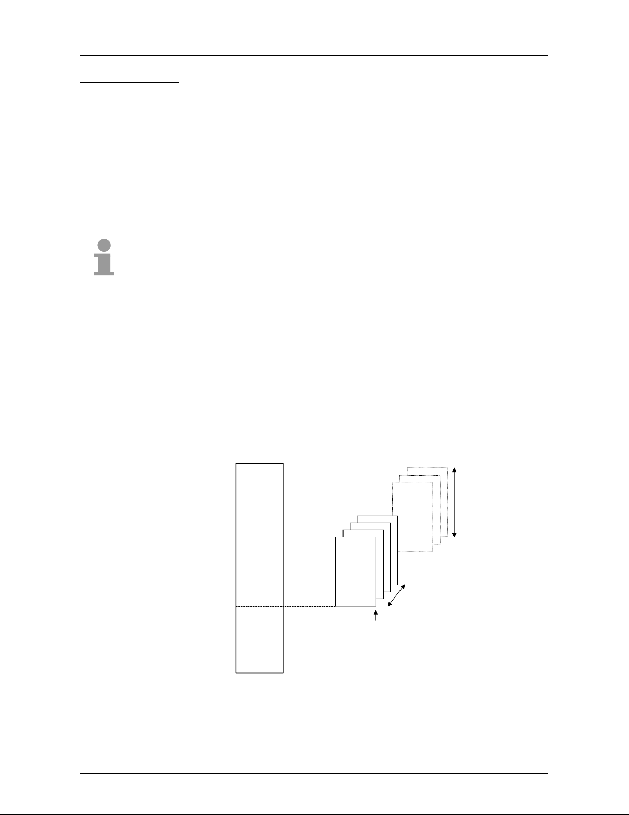
The CPU supports up to 255 page frames with a length of each 1kByte.
The PC may use up to 4 page frames f or t he communicat ion with t he CPU.
Starting with the basic page frame that you have to set, the following 3
ascending page frames are occupied by the PC:
Page frame
Byte 0
Page frame
Byte 1023
b+0
b+1
b+2
b+3
Page frame number = 4
Page frame base b
255
Page frame length = 1K
CPU Address range
256 Page frame
Page frame
interface to
S7-400
from Siemens
Outline
Structure
Page 41

Manual VIPA PC-CPU 486 Chapter 3 BIOS / Register
HB111E - Rev. 02/32 3-15
Index: 298h
Reset Value: Powerup Value: 00h
Access: Read/Write
Bit Description
7 reserved
6 reserved
5 reserved
4 reserved
3 reserved
2 reserved
1 3FF-IRQ, 0=disable, 1=enable
0 3FD-IRQ, 0=disable, 1=enable
The register operation mode (298h) is write-protect ed. This write protect ion
is active after a RESET. With t he following sequences at the reg ister 29Fh
you may enable resp. disable the write protection.
enable write protection: 03h, 06h, 03h, 00h
disable write protection: 03h, 06h, 03h, 01h
IRQ-Req/Ack 299h
Address: 299h
Reset Value: 00h
Powerup Value: 00h
Access: Read/Write
Bit Description
7 reserved
6 reserved
5 reserved
4 reserved
3 reserved
2 reserved
1 Read 1 = Write Cycle Address 3FFh pending, Write 1 clear all 3FF-IRQ Request
0 Read 1 = Write Cycle Address 3FFh pending, Write 1 clear all 3FF-IRQ Request
Operation mode
register 298h
Status and
interrupt register
299h
Page 42

Chapter 3 BIOS / Register Manual VIPA PC-CPU 486
3-16 HB111E - Rev. 02/32
You may initiate an interrupt at the PC by means of a write access of the
CPU to the offset addresses 3FDh and 3FFh.
The according entries containing more detailed information about the
interrupt are stored in the regist er s:
At an interrupt by an access to 3FDh resp. 3FFh an entry in the register
29Ah resp. 29Bh is created. After the start-up and after a RESET the
register contains 00h. This register allows read and write access and it has
the following structure:
IRQ-Req/Ack, pag e frame 0-3, 29Ah 29Bh
Address: 29Ah 29Bh
Reset Value: 00h 00h
Powerup Value: 00h 00h
Access: Read/Write Read/Write
Bit Description
70
60
50
40
3 Read 1=Write Cycle Addr. 3FDh on Page 3+Base pending, Write 1 clear IRQ Request
2 Read 1=Write Cycle Addr. 3FDh on Page 2+Base pending, Write 1 clear IRQ Request
1 Read 1=Write Cycle Addr. 3FDh on Page 1+Base pending, Write 1 clear IRQ Request
0 Read 1=Write Cycle Addr. 3FDh on Page 0+Base pending, Write 1 clear IRQ Request
Address: 29Ch
Reset Value: Powerup Value: 00h
Access: Read/Write
Bit Description
7:0 Page fr ame base address
Address: 29Dh
Reset Value: Powerup Value: 00h
Access: Read only
Bit Description
7:0 Page fr ame select register
Interrupt register
29Ah, 29Bh
Page frame base
29Ch
page frame select
register
29Dh
Page 43

Manual VIPA PC-CPU 486 Chapter 3 BIOS / Register
HB111E - Rev. 02/32 3-17
Address: 29Eh
Access: Read only
Bit Description
7:0 Revision number
Address: 29Fh
Access: Read only
Bit Description
7:0 Identification Number
Information
register
Revision
Identification
Register
29Eh
Device
Identification
Register
29Fh
Page 44

Chapter 3 BIOS / Register Manual VIPA PC-CPU 486
3-18 HB111E - Rev. 02/32
Page 45

Manual VIPA PC-CPU 486 Chapter 4 Deployment of the PC-CPU
HB111E - Rev. 02/32 4-1
Chapter 4 Deployment of the PC-CPU
This chapter describes the deployment of the PC in the S7-400 from
Siemens. The description refers to the communication possibilities with
periphery and CPU and those via Profibus.
The following text describes:
• Overview over the communication possibilities
• Communication with the periphery
• Communication with the CPU
• Profibus comm unication
• Deployment of the CO M modules
Topic Page
Chapter 4 Deployment of the PC-CPU.................................................. 4-1
Overview...............................................................................................4-2
Communication via periphery................................................................4-3
Communication via page frame............................................................4-4
Profibus communication of the PC-CPU 486DPM................................4-7
Project engineering DP master.............................................................4-9
Communication PC with DP master....................................................4-11
Communication by deploying COM modules ......................................4-15
Profibus assembly guidelines..............................................................4-16
Outline
Content
Page 46
Chapter 4 Deployment of the PC-CPU Manual VIPA CP-CPU 486
4-2 HB111E - Rev. 02/32
Overview
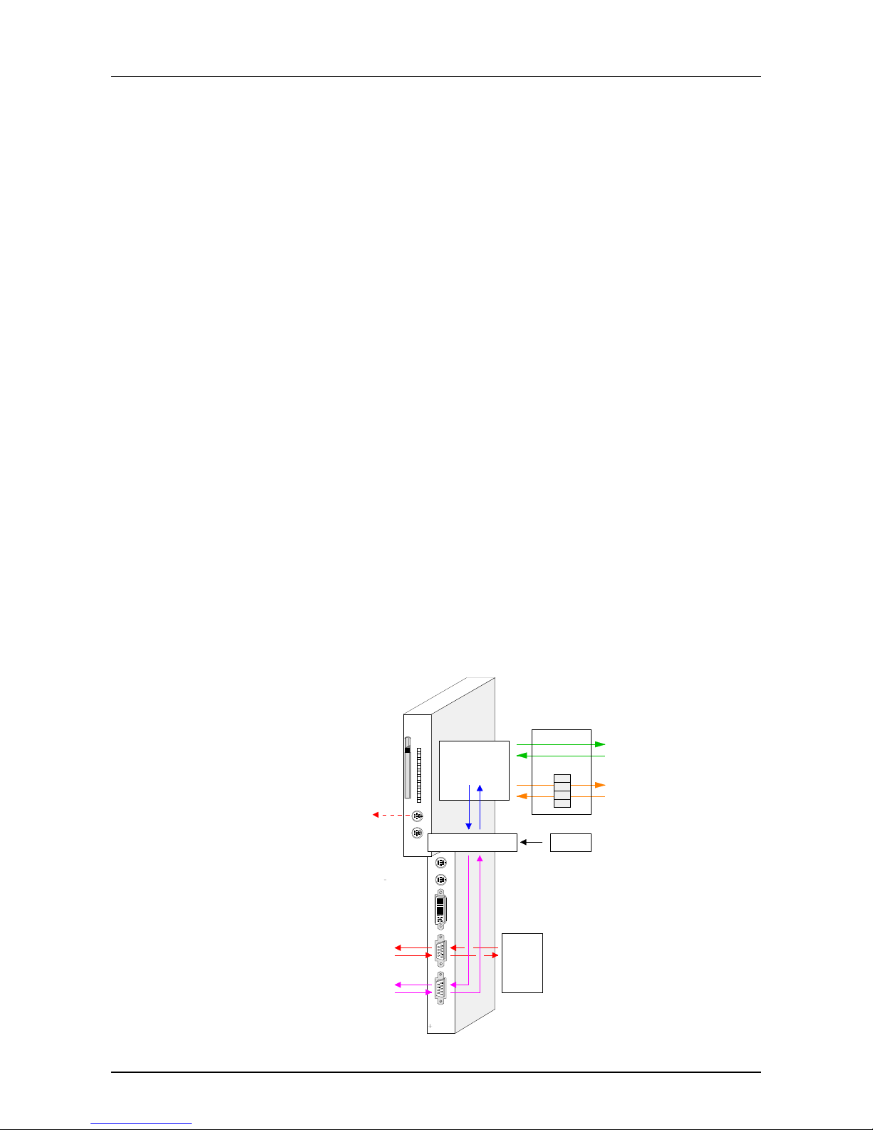
At deployment in a S7-400 system from Siemens you may insert the
PC-CPU 486 into all module rails that have plug-in locations with combined
P- and K-Bus plug. You may deploy the PC as stand-alone CPU or as CP
together with a CPU.
Via C-functions and PLC program you have the following possibilities of
communication:
• Periphery communication with I/O periphery as stand-alone CPU
• Page fr ame communication with a CPU as CP
• Profibus communication of the PC-CPU 486DPM
• Fieldbus communication via Hilscher COM module
For the deployment of the PC-CPU 486 under Profibus you have the
following possibilities:
• You deploy the variant with integrated Profibus master. Hereby the
communication works via a Dualport-RAM. The project engineering of
the Profibus master happens via WinNCS and the access at the PC side
via C-functions.
• You deploy the PC-CPU 486 with a Profibus plug-in module at the COM
module plug-in location. Hereby access and project engineering
functions via the software added to the card.
Here once more all communication possibilities:
X 2
3
4
VIPA 486-1BM00
PC (C-Files)
DP-Maste r (2bf-File)
Profibus DP
Periphery
CPU
page frame
Bus
Hilscher-COM-Out
Hilscher-COM-Diag
Hilscher
Com-
Module
&
Software
WinNCS
General
Deployment under
Profibus
Outline
Page 47
Manual VIPA PC-CPU 486 Chapter 4 Deployment of the PC-CPU
HB111E - Rev. 02/32 4-3
Communication via periphery
At the communication via the periphery there is a communication to the
peripheral modules connected to the backplane bus. For the
communication there is an extensive function library at your disposal,
where more detailed information is to find in the header file and the
sources.
Note!
This kind of direct communicat ion with the peripheral area is only available
if you deploy the PC as stand-alone CPU. The according adjustment has to
be made in the BIOS at the "VIPA Conf iguration". Choose "enable" in the
CPU Mode.
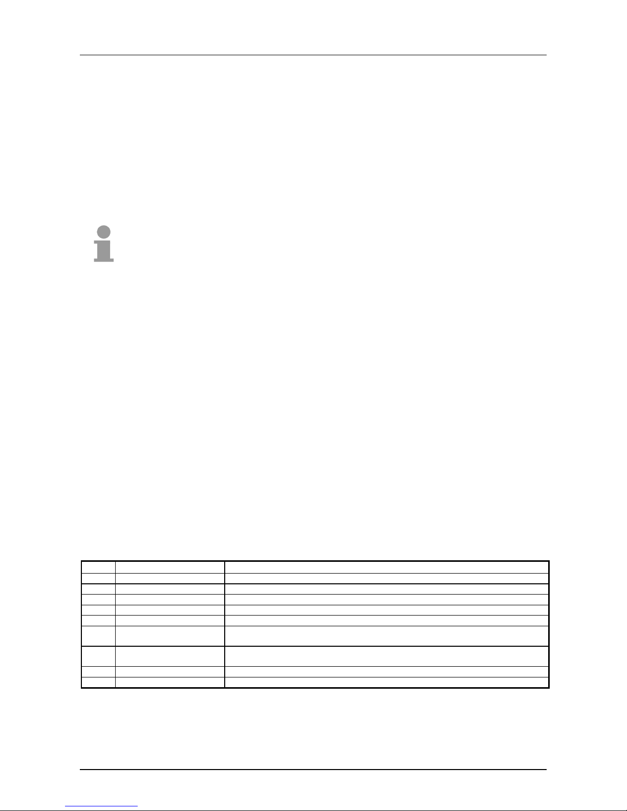
The following functions are at t his t im e available via the library p400_api:
void p400_init (void); //Initializes the backplane bus, has to be called first!
BYTE p400_scan (void); //Scans the backplane bus(detect module configuration) and prepares
//internal structures for I/O access, has to be called second
BYTE p400_di_read (BYTE bSlot, BYTE far * pbBuf, WORD wLength); //Reading a digital module
BYTE p400_do_write (BYTE bSlot, BYTE far * pbBuf, WORD wLength); //Writing a digital module
BYTE p400_ai_read (BYTE bSlot, BYTE far * pbBuf, WORD wLength); //Reading an analog module
BYTE p400_ao_write (BYTE bSlot, BYTE far * pbBuf, WORD wLength); //Writing an analog module
BYTE p400_write_dataset (BYTE bSlot, BYTE bDatasetNumber, BYTE far * pbDataset, BYTE bDatasetLength);
//Writing a record set (Basic function for parameterizing the modules)
BYTE p400_parameterize_default (BYTE bSlot); //Sets a module to the default parameterization state
BYTE p400_parameterize_S7H_6ES7_432_1HF00_0AB0_CT (BYTE bSlot); //Example for the parameterization of this analog
//output
BYTE p400_parameterize_S7H_6ES7_431_1KF00_0AB0_CT (BYTE bSlot); //Example for the parameterization of this analog
//input
The usage of the shown functions is illustrated in the example application
p400test, that you may order at VIPA.
The application p400test provides the following test functions:
Key Command Description
[0] Exit Exit application
[1] ScanSystem Detects the module configuration by a bus scan (has to be called first)
[2] ReadDigitalIn Reading a digital module (dialog slot input)
[3] WriteDigitalOut Writing a digital module (dialog slot input and value)
[4] Parameterize_default Set module group to default parameterization state (dialog slot input)
[5] Parameterize_S7H_6ES7
_432_1HF00_0AB0_CT
Example parameterization of this analog output module
[6] Parameterize_S7H_6ES7
_431_1HF00_0AB0_CT
Example parameterization of this analog input module
[7] ReadAnalogIn Reading an analog module (dialog slot input)
[8] WriteAnalogOut Writing an analog module (dialog slot input and value)
Please regard that the example application executes the function p400_init
automatically.
Outline
Functions of
p400_api
Example program
p400test
Page 48
Chapter 4 Deployment of the PC-CPU Manual VIPA CP-CPU 486
4-4 HB111E - Rev. 02/32
Communication via page frame
For the communication with a CPU the PC supports 4 page frames. The
communication is realized at PLC side via a PLC program and at PC side
via C-functions. A more detailed description of the C-funct ions is to find in
the header file and the sources. You may request a demo application also
to this topic.
Note!
This kind of direct comm unication with a CPU is only possible if you deploy
the PC as CP. The according adjustment has to be made in the BIOS at
the "VIPA Configuration" . Choose "disable" in the CPU Mode.
The project engineering in the hardware configurator from Siemens is as
S5 adapter in the hardware catalogue under simatic400/im-400/s5-adapter
without additional parameters.
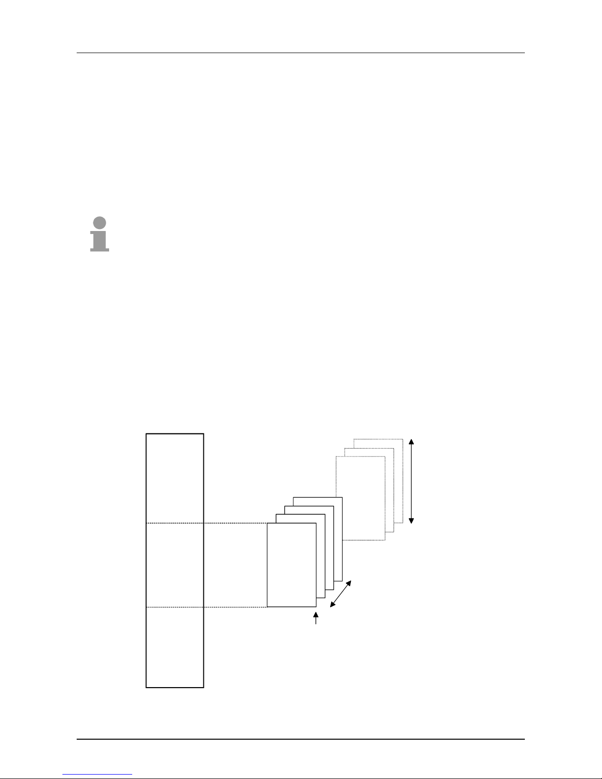
The CPU supports up to 255 page frames with a length of 1k Byte each.
The PC may use up to 4 page frames f or t he communicat ion with t he CPU.
Starting with the base page frame that you have to set, the ascending 3
page frames are occupied by the PC:
Page fram e
Byte 0
Page frame
Byte 1023
b+0
b+1
b+2
b+3
Page frame number = 4
Page frame base b
255
Page frame length = 1K
CPU Address range
256 Page frame
Outline
Page frame
interface
Page 49

Manual VIPA PC-CPU 486 Chapter 4 Deployment of the PC-CPU
HB111E - Rev. 02/32 4-5
The CPU uses the following standard communication functions:
Read functions:
SFC 65514 Read Byte from page frame
SFC 65515 Read word from page frame
SFC 65516 Read double- word from page frame
Before calling the read functions you have to set the pag e frame number
and the address of the Byte to read in AKKU1. The module expects the
page frame number in AKKU1-H and t he address in AKKU1-L.
The read value is returned in AKKU1.
Example: Reading a Byte from page frame 2 of Byte 30
L 2 Page frame number
SLD 16 to AKKU1-H
L 30 Byte address
OD Create AKKU1
UC SFC65514 Call SFC
T MB 18 Save value
Write functions:
SFC 65511 Write Byte to page frame
SFC 65512 Write word to pag e frame
SFC 65513 Write double-word to page frame
Before calling the write functions you have to set the pag e frame number
and the address of the Byte to write in AKKU2. The module expects the
page frame number in AKKU2-H and t he address in AKKU2-L.
The value to write is loaded from AKKU1.
Example: Writ ing a Byte to page frame 1 of Byte 50
L 1 Page frame number
SLD 16 to AKKU1-H
L 50 Byte address
OD Create AKKU1
L MB 20 Value to write in the MB20
UC SFC65514 Call SFC
For using the page frame communication, you need a C-function user
application at the PC. The user application receives the pag e frame data
transferred via the CPU, acknowledges the transmission and transf ers the
data to the CPU. The programming approach is to see in the following
example.
You may request a demo application from VI PA also to this topic.
Functions at the
CPU
Functions at the
PC
Page 50
Chapter 4 Deployment of the PC-CPU Manual VIPA CP-CPU 486
4-6 HB111E - Rev. 02/32
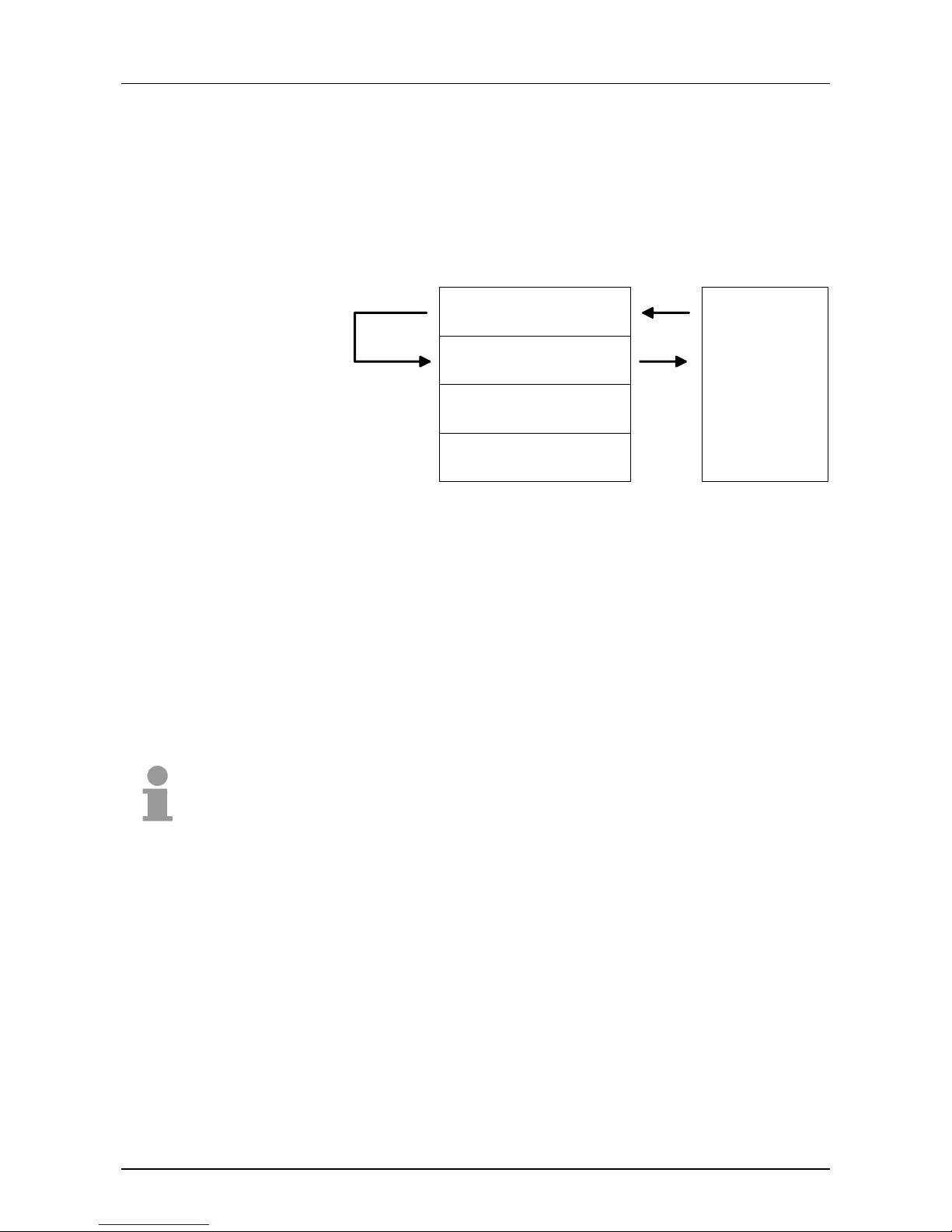
This example outlines the communication between the PC and a CPU. For
this the PC uses page frame 0 for reading and page frame 1 for writing
data. A lock happens via the 1
st
Byte per page frame. The dat a read by the
PC are immediately transferred t o the CPU via page frame 1.
The procedure is illustrated in the f ollowing pict ur e:
Page frame 0
Page frame 1
Page frame 2
Page frame 3
0000h
0400h
0800h
C00h
(1k)
(1k)
(1k)
(1k)
wait until released
write counter
lock (=occupied)
wait until locked
read counter
release
PC side CPU side
Offset: CC00:0 000h
wait until locked,
read all, release
wait until released,
write all, lock
Write process CPU → PC via page frame 0
As soon as the PC released the page frame (Byte 0, Bit 0 = 0) , the content
of the 1
st
word in the user data area is ascended for 1 (MW0) and again
written into the page frame.
Read process PC
→
CPU via page frame 1
As soon as the PC wrote data to the page frame (Byte 0, Bit 0 =1), the
content of the 1
st
word in the user data area is copied to MW2 and the
reading counter MW4 is ascended for 1.
Note!
You may request a demo application from VIPA .
Example for the
page frame
communication
Page 51

Manual VIPA PC-CPU 486 Chapter 4 Deployment of the PC-CPU
HB111E - Rev. 02/32 4-7
Profibus communication of the PC-CPU 486DPM
Profibus is an open fieldbus standard for building, manufacturing and
process automation. Profibus defines the technical and functional
properties of a serial fieldbus system that can be used to create a network
of distributed digital field-automation equipment on the lower
(sensor/actuator level) to middle performance level (process level).
Profibus distinguishes between active stations (masters) and passive
stations (slaves).
Master equipment
Master equipment controls the data traffic on the bus. Ther e may be also
several masters at one Profibus. This is referred to as multi-master
operation. The bus protocol establishes a logical tok en ring bet ween the intelligent devices connected to the bus. Only the master that owns the tok en
communicates with the slaves.
A master may send unsolicited messages if it has the bus access
permission (Token).
The PC-CPU 486DPM has an integrated Profibus-DP m aster.
Slave equipment
Typical slave equipment holds data of peripheral equipment, sensors,
drives, transducers.
These devices do not have bus access permission in accordance with the
Profibus standard. They can only acknowledge messages or transfer
messages to a master if requested by the respective master.
Data is referred to as being consist ent, if it has the same logical contents.
Data that belongs together is: the high- and low-byte of an analog value
(word consistency) and the control and the status byte with the respective
parameter word required to access the registers.
The data consistency during the interaction between the peripherals and
the controller is guaranteed. That means that the data transferred via
Profibus are read resp. written together.
Profibus guarantees the consistency of the required length.
There is a wide range of diagnosis f unctions under Profibus-DP t o allow a
fast error localization. The diagnosis data are broadcasted by the bus
system and summarized at the master.
General
Master and slaves
Data consistency
Diagnosis
Page 52

Chapter 4 Deployment of the PC-CPU Manual VIPA CP-CPU 486
4-8 HB111E - Rev. 02/32
• Max. 125 DP slaves at one DP master - max. 32 slaves/segment
• Max. cable length under RS485 between two stations 1200m
(depending on baudrate)
• The maximum baudrate is 12MBaud
• The Prof ibus addr ess m ay not be changed during operation
For the deployment of the PC-CPU 486 under Profibus you have the
following possibilities:
• You deploy the variant with the integrated Profibus master. Here the
communication happens via a Dualport-RAM. The project engineering of
the Profibus master tak es place via VIPA WinNCS and t he access from
the PC via C-functions.
The DP master allows to connect up to 125 Profibus-DP slaves to the
PC. The master communicates with the slaves and provides the data via
the Dualport-RAM for the PC. Here you may create a maximum of
1024Byte data for inputs and outputs.
• You deploy the PC-CPU 486 together with a Profibus plug-in module at
the COM module plug-in location. Hereby access and project
engineering functions via the soft ware added to the card.
As transfer medium Profibus uses an isolated twisted-pair cable based
upon the RS485 interface. The tr ansfer rate is max. 12 MBaud.
The RS485 interface is working with voltage diff erences. Though it is less
irritable from failures t han a voltage or a current interface. You are able to
configure the network as well linear as in a tree structur e. Your VIPA PCCPU 486 includes a 9pin slot where you connect the Profibus master into
the Profibus network.
The bus structure under RS485 allows an easy connection resp.
disconnection of stations as well as starting the system step by step. Later
expansions don’t have any influence on stations that are already
integrated. The system realizes automatically if one partner had a fail down
or is new in the network.
Every partner of the Profibus network has to identify itself with a certain
address.
You have to assign the address to the VIPA Profibus master during the
project engineering under WinNCS.
Restrictions
Profibus with the
PC-CPU 486
Transfer medium
RS485
Addressing
Page 53
Manual VIPA PC-CPU 486 Chapter 4 Deployment of the PC-CPU
HB111E - Rev. 02/32 4-9
Project engineering DP master
With the help of the project engineering tool W inNCS from VIPA you may
configure your master via the option "Profibus" as well as the according
periphery of your slaves.
The module transfer f unctions of WinNCS allow you numerous possibilities
for the data transfer to your master module.
The DP master reacts like the IM 308-C from Siemens and may also be
configured under "Com Profibus" from Siemens as IM 308-C.
For the project engineering of DP slaves of the different manufact urer s, the
import of a GSD (Gerätestammdat ei = electronic data sheet) allows you to
transfer the funct ionalit y of the slave and its modules into W inNCS.
For including the GSD you close W inNCS and copy the GSD referring to
your slave into the directory ...\VIPA Component Library\WinNCS\GSD\
into the folder German resp. English.
When the copy has been completed you may start W inNCS again. Now
you may use the new options via the slave project window by choosing a
Family and the Station type.
With the projecting tool WinNCS from VIPA you may configure your
Profibus master as follows.
1. For the project engineering of DP slaves of other manufacturers you include the
according GSD in WinNCS.
2.
Start WinNCS and create a new project file via File > create/open under the
option "Profibus".
3.
If not done yet, create a new Profibus function group in the network
window via
and click at [apply] in the parameter window.
4.
Use
to create a Profibus host/master in the network window and add
the Profibus address of your master in the parameter window.
5.
Create a Profibus slave via
. Add the Profibus address, the Family and
the Station type in the parameter window and click at [apply].
6.
Click at
to configure all peripheral modules that are connected to the
Profibus slave via the backplane bus. By means of [Auto] you may start the
automatical address assignment for the periphery and monitor the address
assignment via [MAP]. If you have an intelligent module, like e.g. a CP, you
will see the adjustable parameters.
General
Include GSD in
WinNCS
Project
engineering under
WinNCS
Page 54
Chapter 4 Deployment of the PC-CPU Manual VIPA CP-CPU 486
4-10 HB111E - Rev. 02/32
7. After you have configured all slaves with the depending periphery, the bus
parameters for the Profibus have to be calculated.
Activate the function group Profibus in the network window. Click at the
register "Busparameter" in the network window. Choose a baudrate and click
at [calculate]. The bus parameters are calculated - [apply] them.
Every time you change the assembly of your modules you have to repeat this
calculation!
8. Activate the master level in the network window and export your project into a
2bf-file.
9. Transfer your 2bf-file into your DP master (see also "Transfer project").
For the data transfer from your programming PC to the DP master, you
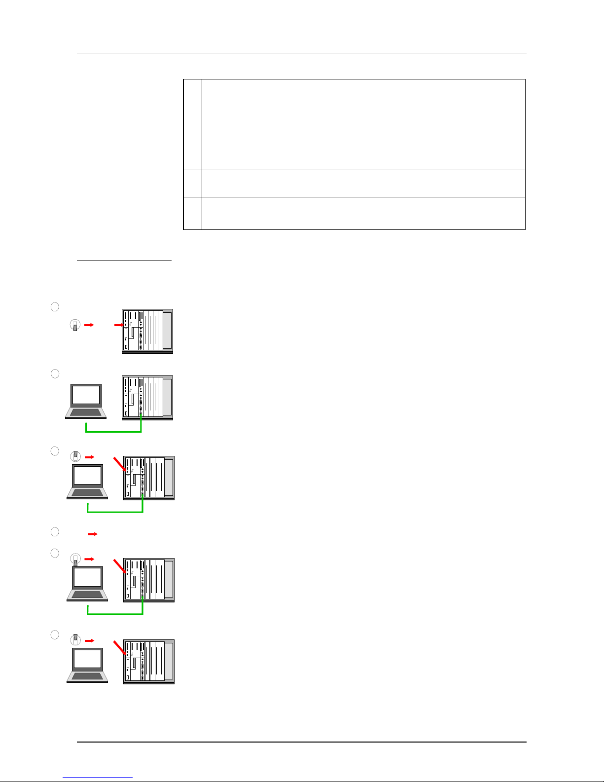
may deploy the VIPA "Green Cable". This enables you to transfer your
project into the internal Flash-ROM of the DP master ser ial via the Profibus
interface.
The "Green Cable" is available at VIPA and has the order number
VIPA 950-0KB00.
Preconditions
The project engineering of your Profibus system is completed and you
stored your project as 2bf-f ile.
Approach
• Assemble your system but leave the voltage supply off.
• Plug the "Gr een Cable" to the serial interface of your progr amming PC
and to the Profibus interf ace of the DP master.
• Turn on the voltag e supply of your PLC.
• Turn on the programming PC and start the SIP-Tool included to
WinNCS. Choose the according COM interface and establish a
connection via [Connect]. As soon as the connection is successful, the
SIP-Tool announces an OK message in the status bar, otherwise an
ERR message.
• Click at [Download], choose your 2bf-file and transfer this into the
DP master.
• Close the connection and the SIP-Tool aft er the data transfer has been
completed.
• Turn of f the voltage supply of your PLC.
• Disconnect the "Green Cable" from the master.
• Connect the master with the Profibus network and turn on the voltage
supply of your PLC again.
Now your master switches automatically to RUN with the created project.
Transfer project
Green Cable
SIP-Tool:
[Connect]
[Download] *.2bf
2
4
S7-400 von Siemens mit
PC-CPU 486 DPM von VIPA
PC-CPU 486 DPM
1
S7-400 von Siemens mit
PC-CPU 486 DPM von VIPA
PC-CPU 486 DPM
ON
OFF
Power Off
Green Cable
3
S7-400 von Siemens mit
PC-CPU 486 DPM von VIPA
PC-CPU 486 DPM
SIP
ON
OFF
Power On
Green Cable
5
S7-400 von Siemens mit
PC-CPU 486 DPM von VIPA
PC-CPU 486 DPM
ON
OFF
Power OFF
6
S7-400 von Siemens mit
PC-CPU 486 DPM von VIPA
PC-CPU 486 DPM
ON
OFF
Power ON
Page 55
Manual VIPA PC-CPU 486 Chapter 4 Deployment of the PC-CPU
HB111E - Rev. 02/32 4-11
Communication PC with DP master
The communication between the PC and the DP master of the PC-CPU
486DPM takes place via a Dualport-RAM. The master communicates with
the slaves and provides the data via the Dualport-RAM for the PC. Here
you may create a maximum of 1024Byte data for inputs and output s.
The PC accesses the Dualport-RAM via C-functions, that will be described
in the following.
At the PC the address range of the Dualport-RAM is fixed. At the DP
master you may access an address range from 0 ... 1023.
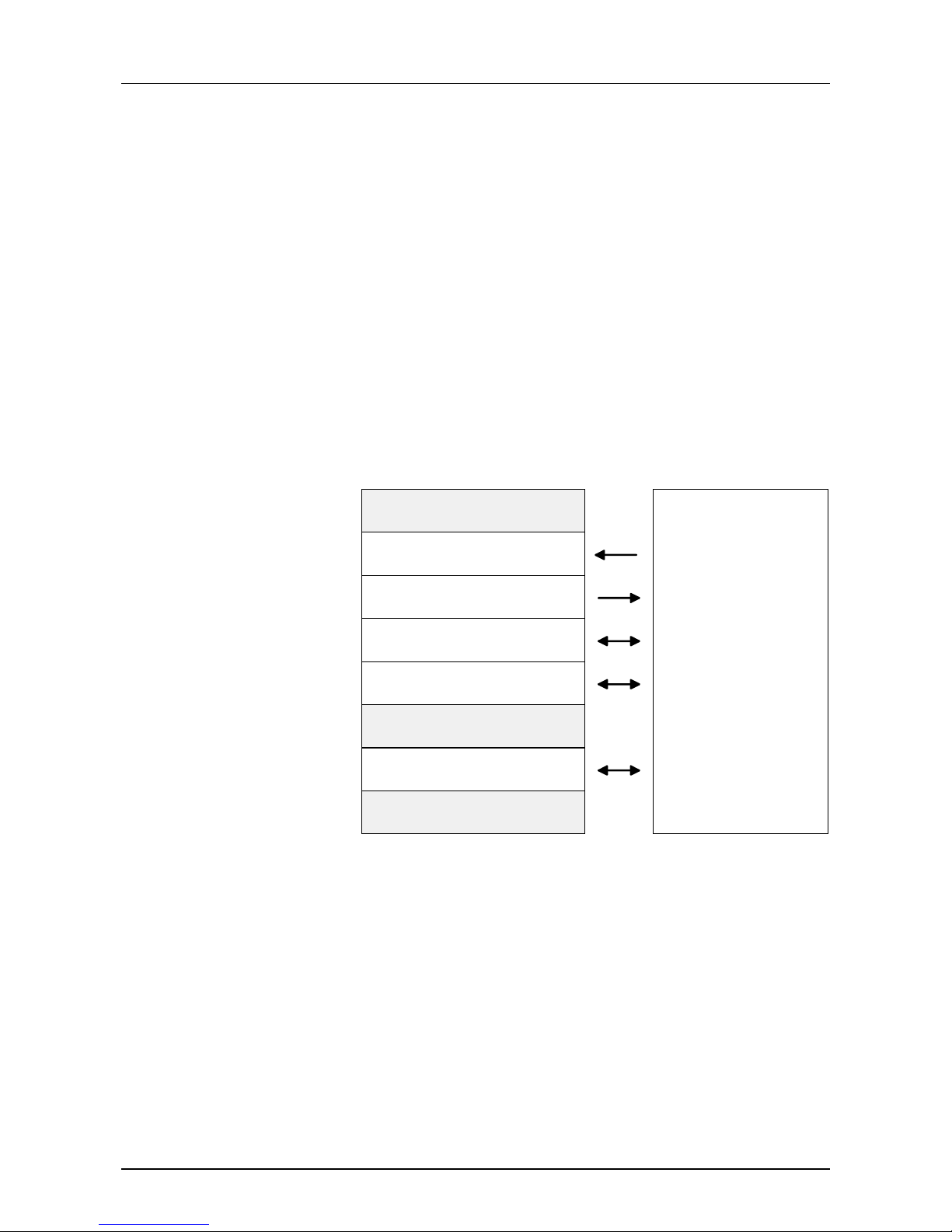
The Dualport-RAM has a size of 8kByte and is organized as follows:
reserved
Profibus-DP input
Profibus-DP output
Block administration input
Block administration output
Flag area
C800:0000h
C800:0400h
C800:0800h
C800:0C00h
C800:1000h
C800:1400h
C800:1800h
C800:1C00h
C800:2000h
reserved
reserved
(1k)
(1k)
(1k)
(1k)
(1k)
(1k)
(1k)
(1k)
WinNCS project engineering0
(address range: 0 ... 1023)
WinNCS project engineering
(address range: 0 ... 1023)
8kByte
Address range PC side
DP master
Outline
Structure
Dualport-RAM
Page 56

Chapter 4 Deployment of the PC-CPU Manual VIPA CP-CPU 486
4-12 HB111E - Rev. 02/32
This is the event sequence to establish a communication:
PC DP master
1. Start-up Start-up
waits for OPCODE
2. sets OPCODE to start
→
Master starts with
*.2bf-configuration
3. waits for INFO_GUELTIG
4.
←
sets INFO_GUELTIG
5. waits for BASP = 0
6. sets BASP = 0
→
releases all outputs
7. reads I/O data cyclically
←→
creates cyclically an
I/O image of all configured DP
slaves.
In the following you find a C-program to illustrate the access to the
DP master.
/*****************************************************************************
* VIPA GmbH *
* *
* Image of the Profibus DP master in the DPRAM of the PC-CPU 486DPM. *
* *
* revision date changes *
* -------------------------------------------------------------------------- *
* 1.00 15.02.2002 created *
* 1.01 15.02.2002 release outputs with BASP *
* 3.00 03.06.2002 new structure of DPRAM. Needs firmware *
* Bb000124.3xx in the master! *
******************************************************************************/
#define VERSION "V300"
#include <conio.h>
#include <stdio.h>
#include <dos.h>
#define BYTE unsigned char
#define WORD unsigned short
//The Dual Port-RAM of the master is addressed from the PC with SEGMENT:OFFSET
//The Dos.h of the Borland C Compiler 4.5 shows e.g. the following definition:
//#define MK_FP(seg,ofs) ((void __seg *)(seg) + (void __near *)(ofs))
///////////////Location of the DP master in the address range of the PC/////////////////////
#define ADR_DPMASTER_SEG 0xC800 //basic-segment address of Dual Port Ram
////////////////////////////////////////////////////////////////////////////////////////////
#define PC_CPU_486_DPM
/////////////////////////////////////////////////////////////////////////////////////////
//
// The DPRAM between CPU and DP master is a 8k memory.
// Every cell of this area may be accessed with R e a d / W r i t e .
// The access has a data width of 8 B i t (= 1Byte).
//
// The DP master notices an 8k area.
// The LED- and VBUS- registers are only visible for the DP master.
// The areas 'PG channel' and 'page frame' may not be accessed
// because they are reserved for other devices!
// The PC notices an 8k area.
//
#define ADR_IM208_FPGA_BASE 0x0uL
#define ADR_IM208_IN (ADR_IM208_FPGA_BASE + 0x0400uL)
#define ADR_IM208_OUT (ADR_IM208_FPGA_BASE + 0x0800uL)
#define ADR_IM208_IN_BLOCKVERWALTUNG (ADR_IM208_FPGA_BASE + 0x0C00uL)
#define ADR_IM208_OUT_BLOCKVERWALTUNG (ADR_IM208_FPGA_BASE + 0x1000uL)
Establishing a
communication
C-program
Page 57

Manual VIPA PC-CPU 486 Chapter 4 Deployment of the PC-CPU
HB111E - Rev. 02/32 4-13
//Flags and Frame of 0x1800uL
#ifdef PC_CPU_486_DPM
#define ADR_IM208_KONSISTENZ_INPUT_HANDSHAKE (ADR_IM208_FPGA_BASE + 0x1AE0uL) //Lock input area
#define ADR_IM208_KONSISTENZ_OUTPUT_HANDSHAKE (ADR_IM208_FPGA_BASE + 0x1AE2uL) //Lock output area
#endif
#define ADR_IM208_MMC_IM208K_READ (ADR_IM208_FPGA_BASE + 0x1AE4uL)
#define ADR_IM208_MMC_IM208K_WRITE (ADR_IM208_FPGA_BASE + 0x1AE6uL)
#define ADR_IM208_MMC_CPU_LOCK (ADR_IM208_FPGA_BASE + 0x1AE8uL)
#define ADR_IM208_MMC_IM208K_LOCK (ADR_IM208_FPGA_BASE + 0x1AEAuL)
#define ADR_IM208_IM208K_ALARM_FLAG (ADR_IM208_FPGA_BASE + 0x1AECuL)
#define ADR_IM208_BASP (ADR_IM208_FPGA_BASE + 0x1AEEuL)
#define ADR_IM208_IM208K_KACHEL_OK (ADR_IM208_FPGA_BASE + 0x1AF0uL)
#define ADR_IM208_LED_STATE (ADR_IM208_FPGA_BASE + 0x1AF2uL)
#define ADR_IM208_INFO_GUELTIG (ADR_IM208_FPGA_BASE + 0x1AF4uL)
#define ADR_IM208_HOCHLAUFVERZOEGERUNG (ADR_IM208_FPGA_BASE + 0x1AF6uL)
#define ADR_IM208_FIRMWARE_VERSION (ADR_IM208_FPGA_BASE + 0x1AF8uL) //4Byte
#define ADR_IM208_HWCONF_RET (ADR_IM208_FPGA_BASE + 0x1AFCuL)
#define ADR_IM208_HWCONF_OPC (ADR_IM208_FPGA_BASE + 0x1AFEuL)
#define ADR_IM208_HWCONF_FRAME (ADR_IM208_FPGA_BASE + 0x1B00uL) //256Byte frame length
//to 0x1C00uL
//----------------------------------------------------------------------------
#define ADR_IM208_VBUS_TYPKENNUNG (ADR_IM208_FPGA_BASE + 0x1F00uL) //visible only at DP master (R/W)
#define ADR_IM208_VBUS_STECKPLATZKENNUNG (ADR_IM208_FPGA_BASE + 0x1F02uL) //visible only at DP master (R)
#define ADR_IM208_VBUS_ADRESSOFFSET (ADR_IM208_FPGA_BASE + 0x1F04uL) //visible only at DP master (R)
#define ADR_IM208_VBUS_INTERRUPT_CONFIG (ADR_IM208_FPGA_BASE + 0x1F06uL) //visible only at DP master (R/W)
#define ADR_IM208_VBUS_INTERRUPT_EVENT (ADR_IM208_FPGA_BASE + 0x1F08uL) //visible only at DP master (R/W)
#define ADR_IM208_REGISTER_LED (ADR_IM208_FPGA_BASE + 0x1F0AuL) //visible only at DP master (W)
//(steuert LEDs bei VBUS und page frame FPGAs)
#define ADR_IM208_VBUS_PARAMETERDATEN (ADR_IM208_FPGA_BASE + 0x1FB0uL) //visible only at DP master (R)
#define ADR_IM208_VBUS_DIAGNOSEBEREICH (ADR_IM208_FPGA_BASE + 0x1FD0uL) //visible only at DP master (W)
#define ADR_IM208_VBUS_ALARMSTATUSBEREICH (ADR_IM208_FPGA_BASE + 0x1FF0uL) //visible only at DP master (W)
//to 0x2000uL
//---------------------------------------------------------------------------/////////////////////////////////////////////////////////////////////////////////////////
/////////////////////////////////////////////////////////////////////////////////////////
// Defines for the block administration in the DPRAM
//
// +-----------------+
// | X D B K . . . . | block administration Byte0
// +-----------------+
// | Y L L L L L L L | block administration Byte1
// +-----------------+
//
// D: Data-Bit: 1=ocuppied with data, 0=free
// B: Block-Bit: 1=Block (>= 2Byte), 0=only 1Byte
// K: Consistency-Bit: 1=consistent, 0=not consistent
// X: Semaphore of the CPU: 1=occupied, 0=free
// Y: Semaphore of the DP master: 1=occupied, 0=free
// LLLLLLL: Block length: 0x00..0x7F = 1...128Byte
//
// [The block administrationByte 0 has 4 free Bits. If the block length of LLLLLLL (1..128)
// is not enough, it would be possible to write blocks between (1..2048)
// by using this 4 Bit.]
//
// 4 cases with examples:
//
// 1. This Byte address is not occupied:
// Block administrationByte 0: x 0 x x x x x x
// The next Byte is again a block administrationByte 0 !
//
// 2. There is only 1Byte:
// Block administrationByte 0: x 1 0 x x x x x
// The next Byte is again a block administrationByte 0 !
//
// 3. There is a non-consistent block of 8Byte:
// Block administrationByte 0: x 1 1 0 x x x x
// Block administrationByte 1: x 0 0 0 0 1 1 1 (Block length: 0x07 = 8Byte)
// The following 6Byte are: 0x00
//
// 4. There is a consistent block of 128Byte:
// Block administrationByte 0: x 1 1 1 x x x x
// Block administrationByte 1: x 1 1 1 1 1 1 1 (Block length: 0x7F = 128Byte)
// The following 126Byte are: 0x00
#define BLOCKVERWALTUNG_X 0x80
#define BLOCKVERWALTUNG_D 0x40
#define BLOCKVERWALTUNG_B 0x20
#define BLOCKVERWALTUNG_K 0x10
#define BLOCKVERWALTUNG_Y 0x80
//////////////////////OPCODE for starting the master//////////////////////////////////////////
#define HWCONF_OPC_WITHOUT 0x0003 //Master is started without hardware configuration; from Flash
//////////////////////Marker; shows master ready/////////////////////////////
#define INFO_GUELTIG 0x82 //Pattern for CPU marker for valid address information
Page 58

Chapter 4 Deployment of the PC-CPU Manual VIPA CP-CPU 486
4-14 HB111E - Rev. 02/32
//////////////////////Constants for consistency control of I/O data/////////////////////////
#define KONSISTENZ_UPDATE_FINISHED 0x0000
#define KONSISTENZ_UPDATE_START 0x0001
////////////////////////////////////////////////////////////////////////////////////////////
//Application
void main(void)
{
BYTE Input;
BYTE sVersion[5]={0,0,0,0,0};
printf("voith.exe %s \n", VERSION);
sVersion[0]= *(BYTE far *) MK_FP( ADR_DPMASTER_SEG, ADR_IM208_FIRMWARE_VERSION +0 );
sVersion[1]= *(BYTE far *) MK_FP( ADR_DPMASTER_SEG, ADR_IM208_FIRMWARE_VERSION +1 );
sVersion[2]= *(BYTE far *) MK_FP( ADR_DPMASTER_SEG, ADR_IM208_FIRMWARE_VERSION +2 );
sVersion[3]= *(BYTE far *) MK_FP( ADR_DPMASTER_SEG, ADR_IM208_FIRMWARE_VERSION +3 );
printf("Firware-Version DPMaster: %s\n", sVersion);
//Commands of the PC as C program:
//
//set OPCODE for start:
//
*(WORD far *) MK_FP( ADR_DPMASTER_SEG, ADR_IM208_HWCONF_OPC ) = HWCONF_OPC_WITHOUT;
//
//
//waits for INFO_GUELTIG
//
while( *(BYTE far *) MK_FP( ADR_DPMASTER_SEG, ADR_IM208_INFO_GUELTIG ) != INFO_GUELTIG )
{
//wait
}
//
//release outputs
//When setting a value > 0, the command output lock BASP is set.
//Then all inputs and outputs are set to 0.
//To enable the output values, set BASP to 0:
//
*(WORD far *) MK_FP( ADR_DPMASTER_SEG, ADR_IM208_BASP ) = 0;
//
//cyclic Read / Write of I/O data
//
while(1)
{
//initiate the update of the inputs
*(WORD far *) MK_FP( ADR_DPMASTER_SEG, ADR_IM208_KONSISTENZ_INPUT_HANDSHAKE ) = KONSISTENZ_UPDATE_START;
//wait for update complete
while( *(WORD far *) MK_FP( ADR_DPMASTER_SEG, ADR_IM208_KONSISTENZ_INPUT_HANDSHAKE ) != KONSISTENZ_UPDATE_FINISHED )
{
//wait
}
//Now the Profibus inputs are consistent in the input area.
/////////////////////////////////////////////////////////////////////////
//Calculate the new output values from the consistent input data
//and write it to the output area of the DPRAM.
//
//e.g. for the master an input byte at address 1 has been configured.
// Reading input address 1:
Input = *(BYTE far *) MK_FP( ADR_DPMASTER_SEG, ADR_IM208_IN +1 );
//
//e.g. for the master an output byte at address 0 has been configured.
// Writing 0x01 to output address 0:
*(BYTE far *) MK_FP( ADR_DPMASTER_SEG, ADR_IM208_OUT +0 ) = 0x01;
//write input of address 1 to output of address 1
*(BYTE far *) MK_FP( ADR_DPMASTER_SEG, ADR_IM208_OUT +1 ) = Input;
/////////////////////////////////////////////////////////////////////////
//Initiate update of outputs
*(WORD far *) MK_FP( ADR_DPMASTER_SEG, ADR_IM208_KONSISTENZ_OUTPUT_HANDSHAKE ) = KONSISTENZ_UPDATE_START;
//wait for update complete
while( *(WORD far *) MK_FP( ADR_DPMASTER_SEG, ADR_IM208_KONSISTENZ_OUTPUT_HANDSHAKE ) != KONSISTENZ_UPDATE_FINISHED )
{
//wait
}
//Now the output data has been put consistent to the Profibus
}
}//end of main()
Page 59

Manual VIPA PC-CPU 486 Chapter 4 Deployment of the PC-CPU
HB111E - Rev. 02/32 4-15
Communication by deploying COM modules
The PC provides an internal plug-in location for Hilscher COM modules. By
deploying pluggable bus modules you may choose between all leading
fieldbus system modules.
Every module includes a detailed description. Further on, you receive a
function library in C as source code, to create own device drivers as well as
a projecting tool.
The COM modules are compact plug-in modules and they include a
complete fieldbus connection at very small dimensions. Here the whole
protocol stack is executed.
The connection to your PC is via a plug.
The data transfer between PC and module takes place via the Dualport-
RAM interface, that may be accessed by means of the included sof t ware.
Together with your COM module the Hilscher company delivers not only a
detailed documentation but also a series of software tools and driver. The
following components are in the consignment:
Toolkit
This C library serves the import of t he COM module into PC applications.
COM interface
The COM interface provides COM components for object-orientated
programming languag es like Visual
C++ or Visual Basic.
Device driver for Windows 9x/NT/2000/XP/CE and Linux
The device driver manages the complete administration of the COM
module in the according operating system.
Projecting tool SyCon
SyCon is a projecting tool with an unique user interface for all COM
modules. As basic for the project engineer ing G SDs (G erätestammdateien)
or Electronic Data Sheets ESD are used. These f iles define the properties
of the bus participants.
Via a graphical editor you build the bus structure and locate the single
participants. The tool also supports detailed diagnosis and commissioning
hints; for e.g. er r or m essages are shown in plain text.
Outline
COM modules
Software tools
Page 60

Chapter 4 Deployment of the PC-CPU Manual VIPA CP-CPU 486
4-16 HB111E - Rev. 02/32
Profibus assembly guidelines
• A VIPA Profibus network may only be built-up in linear structure.
• Profibus exists of minimum one segment with at least one mast er and
one slave.
• Profibus support s m ax. 125 par t icipants.
• For each segment a m ax. of 32 participants is allowed.
• The maximum segment length depends on the baudrate:
9.6...187.5kBaud → 1000m
500kBaud → 400m
1.5MBaud → 200m
3...12MBaud → 100m
• You may build-up a max. of 10 segm ents. The seg ments are connected
together with repeaters. Every repeater is tak en as a par ticipant.
• All participants are comm unicating with the same baudrate. The slaves
are adjusting themselves to this baudrate.
• You have to terminate the bus at bot h ends.
• Master and slaves are combinable at will.
• Assemble your Profibus system with the according modules.
• Choose an address at your bus coupler that is not yet in use.
• Transfer the delivered GSD file into your configuration tool and
configure your system.
• Transf er your project into the master.
• Connect the Prof ibus cable to the coupler and turn on the power supply.
Note!
The Profibus cable has to be terminated with its ripple resistor. Please
make sure to terminate the bus at the particular last participant by
activating the terminating resistor.
General
Assembly and
link-up to Profibus
Page 61
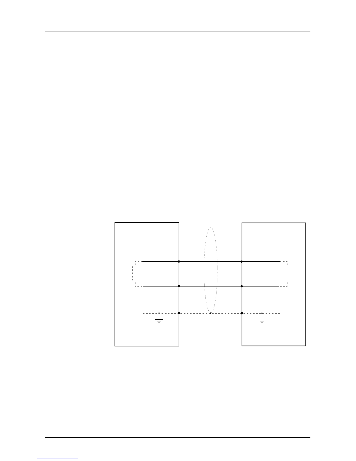
Manual VIPA PC-CPU 486 Chapter 4 Deployment of the PC-CPU
HB111E - Rev. 02/32 4-17
As transfer medium Profibus uses an isolated twisted-pair cable based
upon the RS485 interface.
The RS485 interface is working with voltage diff erences. Though it is less
irritable from failures t han a voltage or a current interface. You are able to
configure the network as well linear as in a tree structure.
At the front side of your PCs is a 9pin slot. Via this slot you connect the
coupler as master directly into your Profibus network.
For every segment a max. of 32 participants is allowed. The single
segments are connected together via repeater s. The max. segment length
depends on the baudrate.
Profibus uses a baudrate between 9.6kBaud and 12MBaud, the slaves are
following automatically. All participants of the network are communicating
with the same baudrate.
The bus structure under RS485 allows an easy connection resp.
disconnection of stations as well as starting the system step by step. Later
expansions don’t have any influence on stations that are already
integrated. The system realizes automatically if one partner had a fail down
or is new in the network.
The picture shows a Profibus connection under RS485 with outlined
terminating resistors:
L2P
Screen
Master Slave
3
8
L2P
3
8
Screen
L2N
L2N
Transfer medium
Page 62
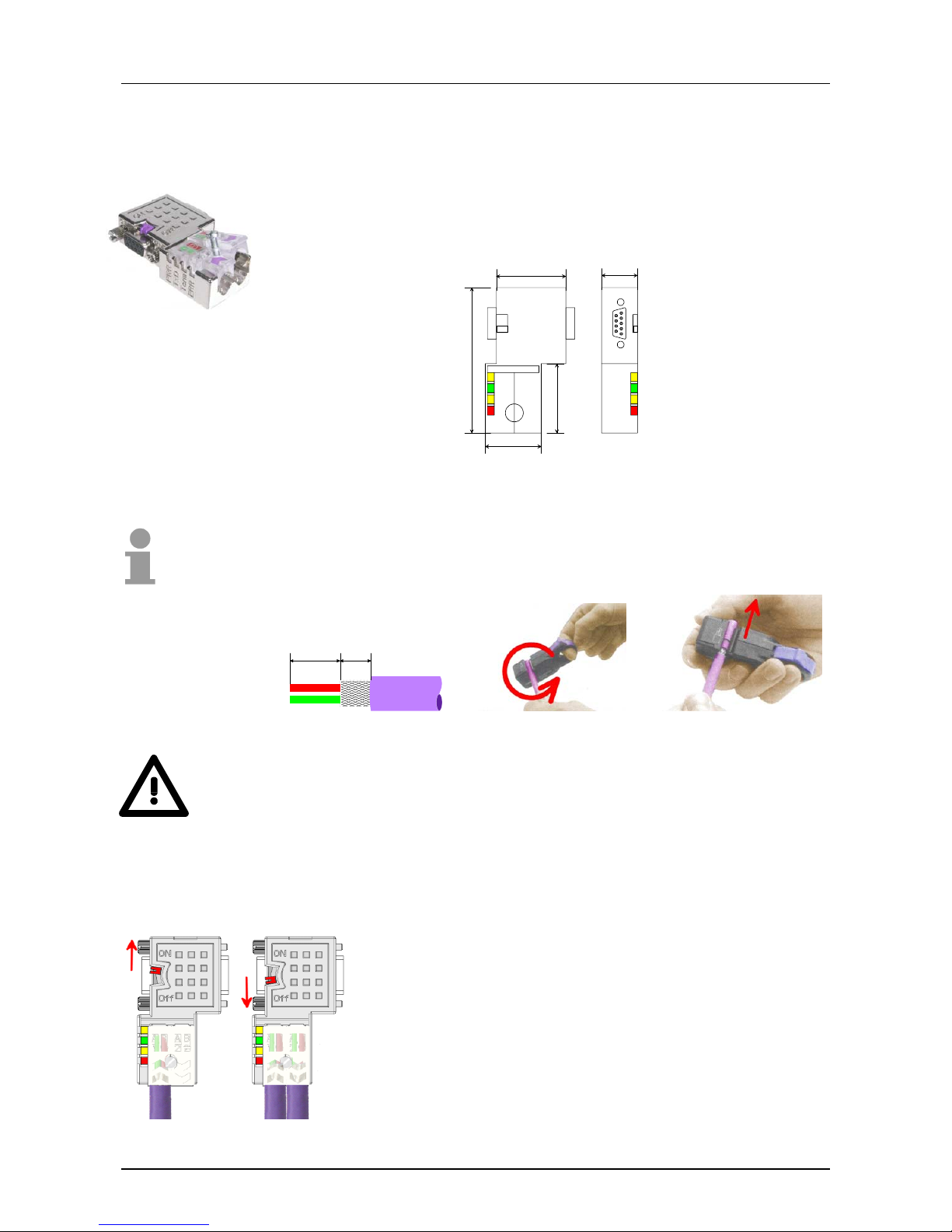
Chapter 4 Deployment of the PC-CPU Manual VIPA CP-CPU 486
4-18 HB111E - Rev. 02/32
In systems with more than two stations all partners are wired in parallel.
For that purpose the bus cable must be connected in a continuous
uninterrupted loop.
Via the order number VIPA 972-0DP10 you may order the bus connector
"EasyConn". This is a bus connector with switchable terminating resistor
and integrated bus diagnosis.
31 15,8
25
65
30,5
PWR
TxD
Term
ERR
ON
OFF
ON
OFF
all in mm
To connect this connector please use the standard Prof ibus cable type A
according to EN50170.
Under the order no. 905-6AA00 VIPA offers the "EasyStrip" deisolating
tool, that makes the connection of the EasyConn much easier.
Attention!
The bus cable has always to be terminated with the ripple resistor to avoid
reflections and therefore comm unication problems!
The bus connector is provided with a switch that may be used to activate a
terminating resistor.
Attention!
The terminating resistor is only eff ective, if the connector
is installed at a slave and the slave is connected to a
power supply.
Note!
A complete description of installation and deployment of
the terminating resistors is delivered with the connector.
Bus connector
Termination
11 6
all in mm
Page 63

Manual VIPA PC-CPU 486 Index
HB111E - Rev. 02/32 A-1
Appendix
A Index
A
Address assignment ................... 3-10
B
Basic CMOS Configuration...........3-4
BIOS setup....................................3-2
Block diagram...............................1-5
Boot drive......................................3-7
C
COM module................................. 2-8
Deployment.............................4-15
Communication possibilities ......... 4-2
CompactFlash......... 2-3; 2-5; 2-9; 3-4
CPU Mode ...........................3-8; 3-13
D
Data consistency...........................4-7
Deisolation lengths......................4-18
Deployment................................... 4-1
Device variants .............................1-4
Diagnostic interface ...................... 2-6
DiskOnChip................................... 2-9
DOC..............................................2-3
DP master.....................................2-3
Dualport-RAM.............................4-11
DVI jack ........................................2-7
E
Environmental conditions..............1-4
H
Hardware description....................2-1
I
Include GSD..................................4-9
J
Jacks and plugs............................2-6
K
Keyboard.......................................2-6
L
LEDs.............................................2-5
Line termination .......................... 4-18
M
Monitor connection ....................... 2-7
P
Page frame communication.......... 4-4
Page frame interface ........... 3-14; 4-4
Periphery communication............. 4-3
Principles...................................... 1-1
Profibus communication...............4-7
Profibus-DP
Project engineering................... 4-9
Profibus-DP
Addressing................................ 4-8
Assembly guidelines............... 4-16
Cabling ................................... 4-17
Communication with PC......... 4-11
Data consistency...................... 4-7
Master....................................... 4-7
Plugs....................................... 4-18
Slaves....................................... 4-7
Transfer project ...................... 4-10
Properties ..................................... 2-3
R
Register description.................... 3-11
RS485 interface
Profibus .................................... 2-8
S
Safety information......................... 1-2
SIP-Tool...................................... 4-10
Structure.......................................2-4
System overview........................... 2-2
T
Technical data ............................ 2-10
V
Version data ................................. 3-8
VIPA Configuration....................... 3-7
W
Watchdog ..................................... 3-8
WinNCS under Profibus-DP......... 4-9
Page 64

Index Manual VIPA PC-CPU 486
A-2 HB111D - Rev. 02/32
M.Stich
 Loading...