

VIPA SPEED7 CPU 313SCDPM, SPEED7 CPU 313SC, CPU 312SC, SPEED7 CPU-SC 312-5BE13, SPEED7 CPU 312SC User Manual
Page 1

CPU-SC | 313-6CF13 | Manual
HB140 | CPU-SC | 313-6CF13 | GB | 15-50
VIPA System 300S
SPEED7 CPU 313SC/DPM
Page 2

313-6CF13_000_CPU 313SC/DPM,1,GB -
© 2015
VIPA GmbH
Ohmstr. 4
91074 Herzogenaurach
Telephone: +49 9132 744-0
Fax: +49 9132 744-1864
Email: [email protected]
Internet: www.vipa.com
Page 3

Table of contents
1 General...................................................................................... 6
1.1 Copyright ©
VIPA GmbH ................................................... 6
1.2 About this manual.............................................................. 7
1.3 Safety information.............................................................. 8
2 Basics..................................................................................... 10
2.1 Safety information for users............................................. 10
2.2 Operating structure of a CPU........................................... 10
2.2.1 General......................................................................... 10
2.2.2 Applications .................................................................. 11
2.2.3 Operands...................................................................... 11
2.3 CPU 313-6CF13............................................................... 12
2.4 General data.................................................................... 13
3 Assembly and installation guidelines.................................. 16
3.1 Installation dimensions..................................................... 16
3.2 Assembly standard bus.................................................... 17
3.3 Cabling............................................................................. 18
3.4 Installation guidelines....................................................... 21
4 Hardware description............................................................ 24
4.1 Properties......................................................................... 24
4.2 Structure........................................................................... 25
4.2.1 General......................................................................... 25
4.2.2 Interfaces...................................................................... 26
4.2.3 In-/Output area CPU 313-6CF13.................................. 28
4.2.4 Memory management................................................... 31
4.2.5 Storage media slot ....................................................... 31
4.2.6 Battery backup for clock and RAM................................ 32
4.2.7 Operating mode switch................................................. 32
4.2.8 LEDs............................................................................. 33
4.3 Technical data.................................................................. 35
5 Deployment CPU 313-6CF13................................................. 47
5.1 Assembly.......................................................................... 47
5.2 Start-up behavior.............................................................. 47
5.3 Addressing....................................................................... 48
5.3.1 Overview....................................................................... 48
5.3.2 Addressing Backplane bus I/O devices......................... 48
5.4 Address assignment......................................................... 49
5.5 Hardware configuration - CPU......................................... 50
5.6 Hardware configuration - I/O modules............................. 51
5.7 Hardware configuration - Ethernet PG/OP channel......... 51
5.8 CPU parametrization........................................................ 53
5.8.1 Parametrization via Siemens CPU................................ 53
5.8.2 CPU parameters........................................................... 53
5.9 Setting VIPA specific CPU parameters............................ 56
5.9.1 Proceeding.................................................................... 56
5.9.2 VIPA specific parameters.............................................. 58
5.10 Project transfer............................................................... 60
5.10.1 Transfer via MPI/PROFIBUS...................................... 60
VIPA System 300S Table of contents
HB140 | CPU-SC | 313-6CF13 | GB | 15-50 3
Page 4

5.10.2 Transfer via Ethernet................................................... 62
5.10.3 Transfer via MMC........................................................ 63
5.11 Access to the internal Web page................................... 64
5.12 Operating modes............................................................ 66
5.12.1 Overview..................................................................... 66
5.12.2 Function security......................................................... 68
5.13 Overall reset................................................................... 68
5.14 Firmware update............................................................ 70
5.15 Reset to factory setting.................................................. 73
5.16 Slot for storage media.................................................... 73
5.17 Memory extension with MCC......................................... 74
5.18 Extended know-how protection...................................... 75
5.19 MMC-Cmd - Auto commands......................................... 77
5.20 VIPA specific diagnostic entries..................................... 79
5.21 Control and monitoring of variables with test functions.. 94
6 Deployment I/O periphery..................................................... 96
6.1 Overview.......................................................................... 96
6.2 In-/Output area CPU 313-6CF13..................................... 97
6.3 Address assignment....................................................... 100
6.4 Digital part...................................................................... 101
6.4.1 Access to the I/O area................................................. 103
6.4.2 Parameterization - Digital part..................................... 104
6.5 Counter.......................................................................... 104
6.5.1 Counter - Fast introduction.......................................... 104
6.5.2 SFB 47 - COUNT - Counter controlling....................... 109
6.5.3 Counter - Functions..................................................... 114
6.5.4 Counter - Additional functions..................................... 119
6.6 Frequency measurement............................................... 126
6.6.1 Overview..................................................................... 126
6.6.2 Inputs for the frequency measurement....................... 127
6.6.3 Parameterization......................................................... 128
6.6.4 SFB 48 - FREQUENC - Frequency measurement...... 129
6.7 Pulse width modulation - PWM...................................... 132
6.7.1 Overview..................................................................... 132
6.7.2 Parameterization......................................................... 134
6.7.3 SFB 49 - PULSE - Pulse width modulation................. 136
6.8 Diagnostic and interrupt................................................. 139
6.8.1 Process interrupt......................................................... 139
6.8.2 Diagnostic interrupt..................................................... 141
7 Deployment PtP communication........................................ 149
7.1 Fast introduction............................................................. 149
7.2 Principle of the data transfer.......................................... 149
7.3 Deployment of RS485 interface for PtP ........................ 150
7.4 Parametrization.............................................................. 153
7.4.1 FC/SFC 216 - SER_CFG............................................ 153
7.5 Communication.............................................................. 156
7.5.1 Overview..................................................................... 156
7.5.2 FC/SFC 217 - SER_SND............................................ 157
7.5.3 FC/SFC 218 - SER_RCV............................................ 162
VIPA System 300STable of contents
HB140 | CPU-SC | 313-6CF13 | GB | 15-50 4
Page 5

7.6 Protocols and procedures ............................................. 164
7.7 Modbus - Function codes .............................................. 168
7.8 Modbus - Example communication................................ 173
8 Deployment PROFIBUS communication........................... 176
8.1 Overview........................................................................ 176
8.2 Fast introduction............................................................. 176
8.3 Hardware configuration - CPU....................................... 177
8.4 Deployment as PROFIBUS DP master.......................... 178
8.5 Deployment as PROFIBUS DP slave............................ 179
8.6 PROFIBUS installation guidelines.................................. 181
8.7 Commissioning and Start-up behavior........................... 184
9 WinPLC7............................................................................... 186
9.1 System conception......................................................... 186
9.2 Installation...................................................................... 186
9.3 Example project engineering.......................................... 188
9.3.1 Job definition............................................................... 188
9.3.2 Project engineering..................................................... 188
9.3.3 Test the PLC program in the Simulator....................... 194
9.3.4 Transfer PLC program to CPU and its execution........ 195
10 Configuration with TIA Portal............................................. 197
10.1 TIA Portal - Work environment .................................... 197
10.1.1 General..................................................................... 197
10.1.2 Work environment of the TIA Portal.......................... 197
10.2 TIA Portal - Hardware configuration - CPU ................. 198
10.3 TIA Portal - Hardware configuration - I/O modules...... 199
10.4 TIA Portal - Hardware configuration - Ethernet PG/OP
channel......................................................................... 200
10.5 TIA Portal - Include VIPA library.................................. 203
10.6 TIA Portal - Project transfer.......................................... 203
VIPA System 300S Table of contents
HB140 | CPU-SC | 313-6CF13 | GB | 15-50 5
Page 6

1 General
1.1 Copyright © VIPA GmbH
This document contains proprietary information of VIPA and is not to
be disclosed or used except in accordance with applicable agreements.
This material is protected by the copyright laws. It may not be reproduced, distributed, or altered in any fashion by any entity (either
internal or external to VIPA), except in accordance with applicable
agreements, contracts or licensing, without the express written consent of VIPA and the business management owner of the material.
For permission to reproduce or distribute, please contact: VIPA,
Gesellschaft für Visualisierung und Prozessautomatisierung mbH
Ohmstraße 4, D-91074 Herzogenaurach, Germany
Tel.: +49 9132 744 -0
Fax.: +49 9132 744-1864
EMail: [email protected]
http://www.vipa.com
Every effort has been made to ensure that the information
contained in this document was complete and accurate at
the time of publishing. Nevertheless, the authors retain the
right to modify the information.
This customer document describes all the hardware units
and functions known at the present time. Descriptions may
be included for units which are not present at the customer
site. The exact scope of delivery is described in the
respective purchase contract.
Hereby, VIPA GmbH declares that the products and systems are in
compliance with the essential requirements and other relevant provisions. Conformity is indicated by the CE marking affixed to the
product.
For more information regarding CE marking and Declaration of Conformity (DoC), please contact your local VIPA customer service
organization.
All Rights Reserved
CE Conformity Declaration
Conformity Information
VIPA System 300SGeneral
Copyright © VIPA GmbH
HB140 | CPU-SC | 313-6CF13 | GB | 15-50 6
Page 7

VIPA, SLIO, System 100V, System 200V, System 300V, System
300S, System 400V, System 500S and Commander Compact are
registered trademarks of VIPA Gesellschaft für Visualisierung und
Prozessautomatisierung mbH.
SPEED7 is a registered trademark of profichip GmbH.
SIMATIC, STEP, SINEC, TIA Portal, S7-300 and S7-400 are registered trademarks of Siemens AG.
Microsoft and Windows are registered trademarks of Microsoft Inc.,
USA.
Portable Document Format (PDF) and Postscript are registered trademarks of Adobe Systems, Inc.
All other trademarks, logos and service or product marks specified
herein are owned by their respective companies.
Contact your local VIPA Customer Service Organization representative if you wish to report errors or questions regarding the contents of
this document. If you are unable to locate a customer service centre,
contact VIPA as follows:
VIPA GmbH, Ohmstraße 4, 91074 Herzogenaurach, Germany
Telefax: +49 9132 744-1204
EMail: [email protected]
Contact your local VIPA Customer Service Organization representative if you encounter problems with the product or have questions
regarding the product. If you are unable to locate a customer service
centre, contact VIPA as follows:
VIPA GmbH, Ohmstraße 4, 91074 Herzogenaurach, Germany
Tel.: +49 9132 744-1150 (Hotline)
EMail: [email protected]
1.2
About this manual
This manual describes the SPEED7 CPU-SC 313-6CF13 of the
System 300S from VIPA. It contains a description of the construction,
project implementation and usage.
Product Order number as of state:
CPU-HW CPU-FW DPM-FW
CPU 313SC/DPM 313-6CF13 02 V3.6.0 V3.2.8
The manual is targeted at users who have a background in automation technology.
The manual consists of chapters. Every chapter provides a self-contained description of a specific topic.
Trademarks
Information product
support
Technical support
Objective and contents
Target audience
Structure of the manual
VIPA System 300S General
About this manual
HB140 | CPU-SC | 313-6CF13 | GB | 15-50 7
Page 8
The following guides are available in the manual:
n An overall table of contents at the beginning of the manual
n References with page numbers
The manual is available in:
n printed form, on paper
n in electronic form as PDF-file (Adobe Acrobat Reader)
Important passages in the text are highlighted by following icons and
headings:
DANGER!
Immediate or likely danger. Personal injury is possible.
CAUTION!
Damages to property is likely if these warnings are not
heeded.
Supplementary information and useful tips.
1.3 Safety information
The system is constructed and produced for:
n communication and process control
n industrial applications
n operation within the environmental conditions specified in the
technical data
n installation into a cubicle
DANGER!
This device is not certified for applications in
–
in explosive environments (EX-zone)
The manual must be available to all personnel in the
n project design department
n installation department
n commissioning
n operation
Guide to the document
Availability
Icons Headings
Applications conforming with specifications
Documentation
VIPA System 300SGeneral
Safety information
HB140 | CPU-SC | 313-6CF13 | GB | 15-50 8
Page 9

CAUTION!
The following conditions must be met before using or
commissioning the components described in this
manual:
– Hardware modifications to the process control system
should only be carried out when the system has been
disconnected from power!
–
Installation and hardware modifications only by properly trained personnel.
– The national rules and regulations of the respective
country must be satisfied (installation, safety, EMC ...)
National rules and regulations apply to the disposal of the unit!Disposal
VIPA System 300S General
Safety information
HB140 | CPU-SC | 313-6CF13 | GB | 15-50 9
Page 10
2 Basics
2.1 Safety information for users
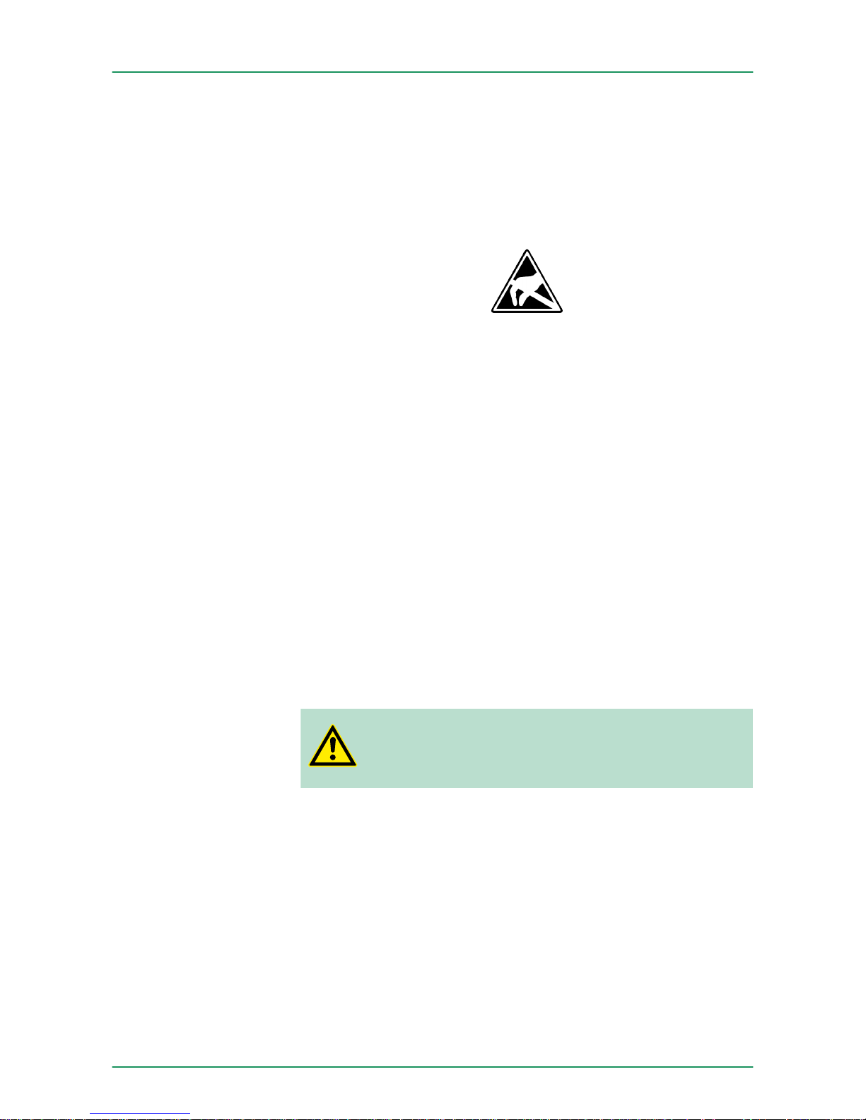
VIPA modules make use of highly integrated components in MOSTechnology. These components are extremely sensitive to over-voltages that can occur during electrostatic discharges. The following
symbol is attached to modules that can be destroyed by electrostatic
discharges.
The Symbol is located on the module, the module rack or on packing
material and it indicates the presence of electrostatic sensitive equipment. It is possible that electrostatic sensitive equipment is destroyed
by energies and voltages that are far less than the human threshold
of perception. These voltages can occur where persons do not discharge themselves before handling electrostatic sensitive modules
and they can damage components thereby, causing the module to
become inoperable or unusable. Modules that have been damaged
by electrostatic discharges can fail after a temperature change,
mechanical shock or changes in the electrical load. Only the consequent implementation of protection devices and meticulous attention
to the applicable rules and regulations for handling the respective
equipment can prevent failures of electrostatic sensitive modules.
Modules must be shipped in the original packing material.
When you are conducting measurements on electrostatic sensitive
modules you should take the following precautions:
n Floating instruments must be discharged before use.
n Instruments must be grounded.
Modifying electrostatic sensitive modules you should only use soldering irons with grounded tips.
CAUTION!
Personnel and instruments should be grounded when
working on electrostatic sensitive modules.
2.2 Operating structure of a CPU
2.2.1
General
The CPU contains a standard processor with internal program
memory. In combination with the integrated SPEED7 technology the
unit provides a powerful solution for process automation applications
within the System 300S family. A CPU supports the following modes
of operation:
n cyclic operation
n timer processing
n alarm controlled operation
n priority based processing
Handling of electrostatic sensitive modules
Shipping of modules
Measurements and
alterations on electrostatic sensitive modules
VIPA System 300SBasics
Operating structure of a CPU > General
HB140 | CPU-SC | 313-6CF13 | GB | 15-50 10
Page 11

Cyclicprocessing represents the major portion of all the processes
that are executed in the CPU. Identical sequences of operations are
repeated in a never-ending cycle.
Where a process requires control signals at constant intervals you
can initiate certain operations based upon a timer, e.g. not critical
monitoring functions at one-second intervals.
If a process signal requires a quick response you would allocate this
signal to an alarm controlled procedure. An alarm can activate a
procedure in your program.
The above processes are handled by the CPU in accordance with
their priority. Since a timer or an alarm event requires a quick reaction, the CPU will interrupt the cyclic processing when these high-priority events occur to react to the event. Cyclic processing will resume,
once the reaction has been processed. This means that cyclic processing has the lowest priority.
2.2.2
Applications
The program that is present in every CPU is divided as follows:
n System routine
n User application
The system routine organizes all those functions and procedures of
the CPU that are not related to a specific control application.
This consists of all the functions that are required for the processing
of a specific control application. The operating modules provide the
interfaces to the system routines.
2.2.3
Operands
The following series of operands is available for programming the
CPU:
n Process image and periphery
n Bit memory
n Timers and counters
n Data blocks
The user application can quickly access the process image of the
inputs and outputs PIO/PII. You may manipulate the following types
of data:
n individual Bits
n Bytes
n Words
n Double words
Cyclic processing
Timer processing
Alarm controlled processing
Priority based processing
System routine
User application
Process image and
periphery
VIPA System 300S Basics
Operating structure of a CPU > Operands
HB140 | CPU-SC | 313-6CF13 | GB | 15-50 11
Page 12

You may also gain direct access to peripheral modules via the bus
from user application. The following types of data are available:
n Bytes
n Words
n Blocks
The bit memory is an area of memory that is accessible by means of
certain operations. Bit memory is intended to store frequently used
working data.
You may access the following types of data:
n individual Bits
n Bytes
n Words
n Double words
In your program you may load cells of the timer with a value between
10ms and 9990s. As soon as the user application executes a startoperation, the value of this timer is decremented by the interval that
you have specified until it reaches zero.
You may load counter cells with an initial value (max. 999) and increment or decrement these when required.
A data block contains constants or variables in the form of bytes,
words or double words. You may always access the current data
block by means of operands.
You may access the following types of data:
n individual Bits
n Bytes
n Words
n Double words
2.3 CPU 313-6CF13
The CPU 313-6CF13 bases upon the SPEED7 technology. This supports the CPU at programming and communication by means of coprocessors that causes a power improvement for highest needs.
n The CPU is programmed in STEPÒ7 from Siemens. For this you
may use the SIMATIC Manager or TIA Portal from Siemens. Here
the instruction set of the S7-400 from Siemens is used.
n Modules and CPUs of the System 300S from VIPA and Siemens
may be used at the bus as a mixed configuration.
n The user application is stored in the battery buffered RAM or on
an additionally pluggable MMC storage module.
n The CPU 313-6CF13 is configured as CPU 313C-2DP (6ES7
313-6CF03-0AB0 V2.6) from Siemens.
Bit Memory
Timers and counters
Data Blocks
Overview
VIPA System 300SBasics
CPU 313-6CF13
HB140 | CPU-SC | 313-6CF13 | GB | 15-50 12
Page 13

The CPU has an integrated memory. Information about the capacity
of the memory may be found at the front of the CPU. The memory is
divided into the following parts:
n Load memory 512kbyte
n Code memory (50% of the work memory)
n Data memory (50% of the work memory)
n Work memory 128kbyte
–
There is the possibility to extend the work memory to its maximum printed capacity 512kbyte by means of a MCC memory
extension card.
The CPU has a PROFIBUS/PtP interface with a fix pinout. After an
overall reset the interface is deactivated. By appropriate configuration, the following functions for this interface may be enabled:
n PROFIBUS DP master operation: Configuration via PROFIBUS
sub module with ‘Operation mode’ master in the hardware configuration.
n PROFIBUS DP slave operation: Configuration via PROFIBUS sub
module with ‘Operation mode’ slave in the hardware configuration.
n PtP functionality: Configuration as virtual PROFIBUS master
system by including the VIPA SPEEDBUS.GSD.
The CPU has an Ethernet interface for PG/OP communication. After
assigning IP address parameters with your configuration tool, via the
"PLC" functions you may directly access the Ethernet PG/OP channel
and program res. remote control your CPU. You may also access the
CPU with a visualization software via these connections.
n Wiring by means of spring pressure connections (CageClamps) at
the front connector
n Core cross-section 0.08...2.5mm
2
n Total isolation of the wiring at module change
n Potential separation of all modules to the backplane bus
Dimensions of the basic enclosure:
n 2tier width: (WxHxD) in mm: 80x125x120
The CPU comes with an integrated power supply. The power supply
is to be supplied with DC 24V. By means of the supply voltage, the
internal electronic is supplied as well as the connected modules via
backplane bus. The power supply is protected against inverse polarity
and overcurrent.
2.4
General data
Conformity and approval
Conformity
CE 2006/95/EG Low-voltage directive
Memory
Integrated PROFIBUS
DP master/slave respectively PtP functionality
Integrated Ethernet
PG/OP
channel
Operation Security
Dimensions/ Weight
Integrated power supply
VIPA System 300S Basics
General data
HB140 | CPU-SC | 313-6CF13 | GB | 15-50 13
Page 14

Conformity and approval
2004/108/EG EMC directive
Approval
UL UL 508 Approval for USA and Canada
others
RoHS 2011/65/EU Product is lead-free; Restriction of the use of
certain hazardous substances in electrical and
electronic equipment
Protection of persons and device protection
Type of protection - IP20
Electrical isolation
to the field bus - electrically isolated
to the process level - electrically isolated
Insulation resistance -
Insulation voltage to reference earth
Inputs / outputs - AC / DC 50V, test voltage AC 500V
Protective measures - against short circuit
Environmental conditions to EN 61131-2
Climatic
Storage / transport EN 60068-2-14 -25…+70°C
Operation
Horizontal installation hanging EN 61131-2 0…+60°C
Horizontal installation lying EN 61131-2 0…+55°C
Vertical installation EN 61131-2 0…+50°C
Air humidity EN 60068-2-30 RH1 (without condensation, rel. humidity 10…
95%)
Pollution EN 61131-2 Degree of pollution 2
Installation altitude max. - 2000m
Mechanical
Oscillation EN 60068-2-6 1g, 9Hz ... 150Hz
Shock EN 60068-2-27 15g, 11ms
VIPA System 300SBasics
General data
HB140 | CPU-SC | 313-6CF13 | GB | 15-50 14
Page 15

Mounting conditions
Mounting place - In the control cabinet
Mounting position - Horizontal and vertical
EMC Standard Comment
Emitted interference
EN 61000-6-4 Class A (Industrial area)
Noise immunity
zone B
EN 61000-6-2 Industrial area
EN 61000-4-2
ESD
8kV at air discharge (degree of severity 3),
4kV at contact discharge (degree of severity
2)
EN 61000-4-3 HF field immunity (casing)
80MHz … 1000MHz, 10V/m, 80% AM (1kHz)
1.4GHz ... 2.0GHz, 3V/m, 80% AM (1kHz)
2GHz ... 2.7GHz, 1V/m, 80% AM (1kHz)
EN 61000-4-6 HF conducted
150kHz … 80MHz, 10V, 80% AM (1kHz)
EN 61000-4-4 Burst, degree of severity 3
EN 61000-4-5 Surge, installation class 3 *
*) Due to the high-energetic single pulses with Surge an appropriate external protective circuit with lightning protection elements like conductors
for lightning and overvoltage is necessary.
VIPA System 300S Basics
General data
HB140 | CPU-SC | 313-6CF13 | GB | 15-50 15
Page 16
3 Assembly and installation guidelines
3.1 Installation dimensions
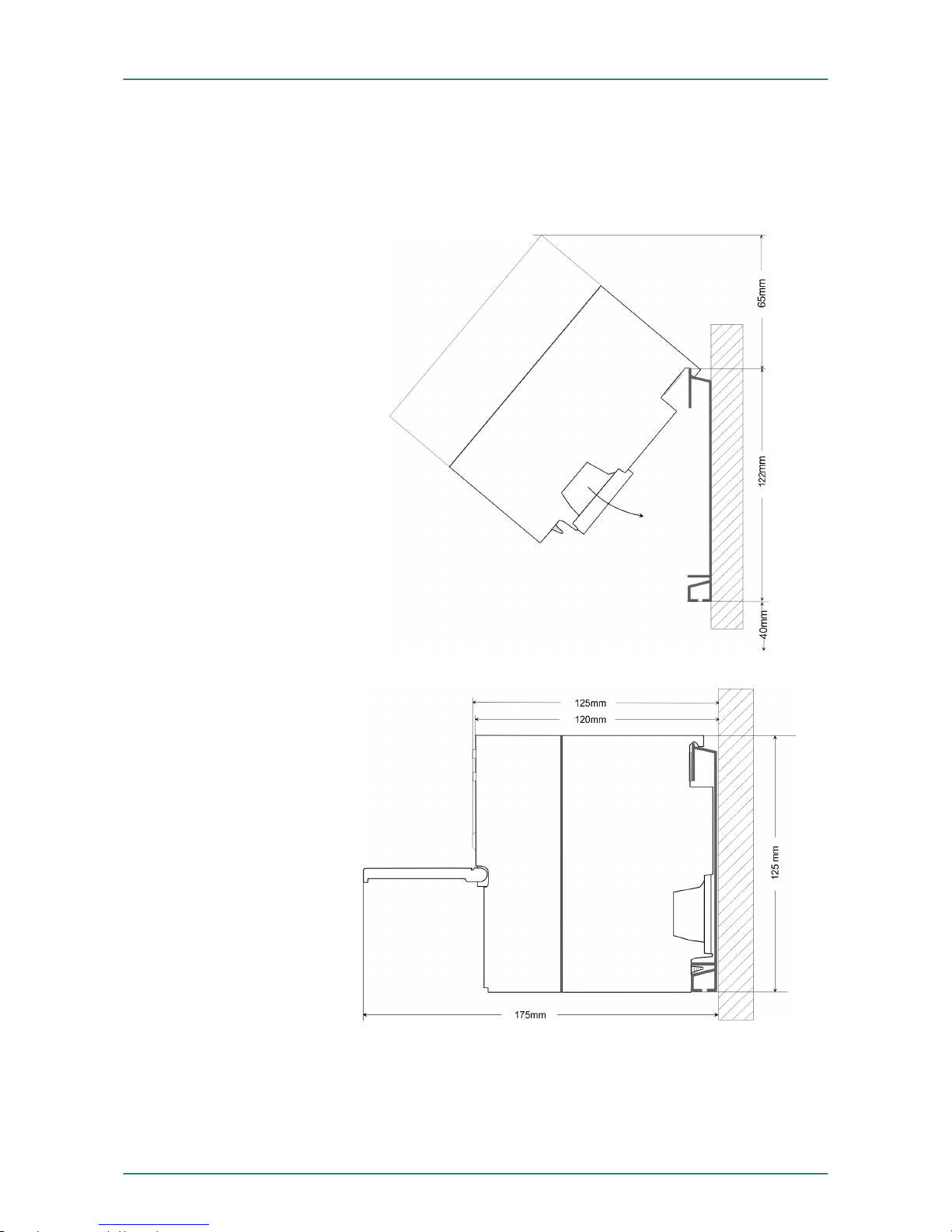
2tier width (WxHxD) in mm: 80 x 125 x 120Dimensions Basic
enclosure
Dimensions
Installation dimensions
VIPA System 300SAssembly and installation guidelines
Installation dimensions
HB140 | CPU-SC | 313-6CF13 | GB | 15-50 16
Page 17
3.2 Assembly standard bus
The single modules are directly installed on a profile rail and connected via the backplane bus connector. Before installing the
modules you have to clip the backplane bus connector to the module
from the backside. The backplane bus connector is delivered together
with the peripheral modules.
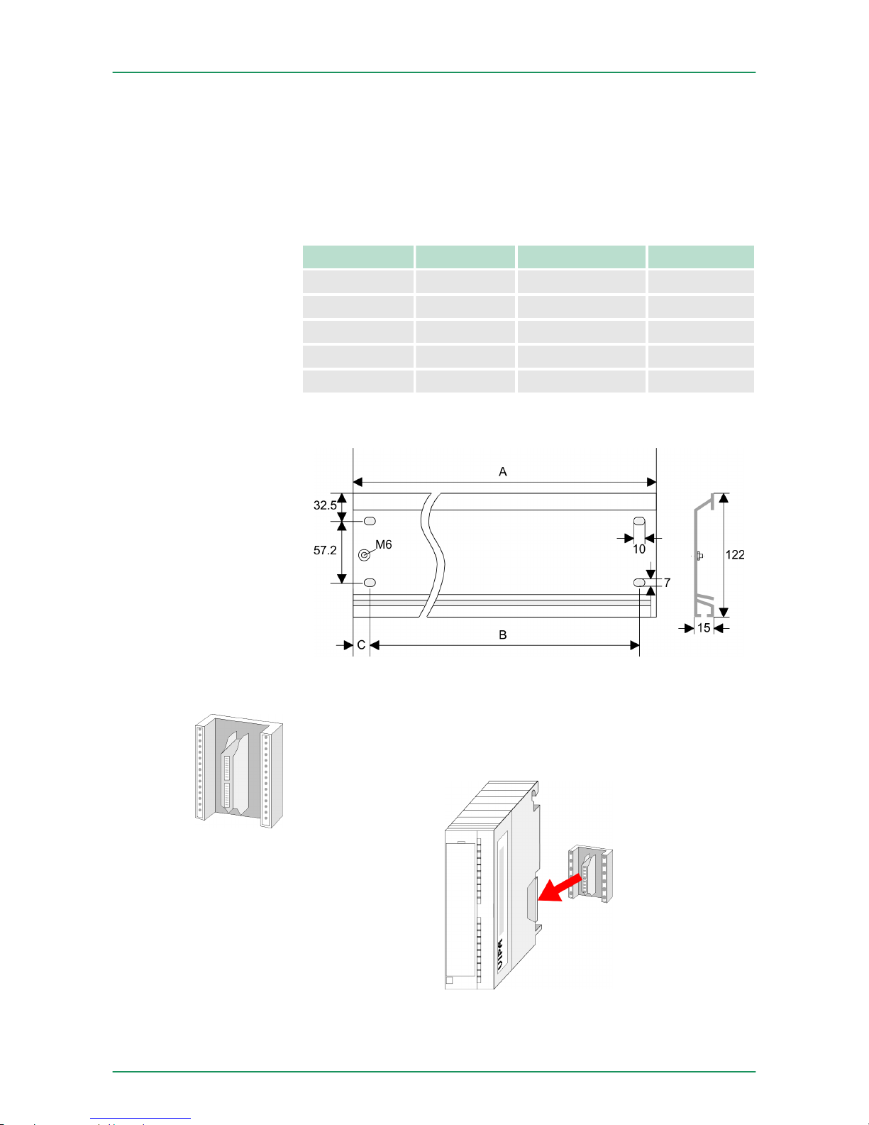
Order number A B C
390-1AB60 160 140 10
390-1AE80 482 466 8.3
390-1AF30 530 500 15
390-1AJ30 830 800 15
390-9BC00* 2000 Drillings only left 15
*) Unit pack: 10 pieces
Measures in mm
For the communication between the modules the System 300S uses
a backplane bus connector. Backplane bus connectors are included
in the delivering of the peripheral modules and are clipped at the
module from the backside before installing it to the profile rail.
General
Profile rail
Bus connector
VIPA System 300S Assembly and installation guidelines
Assembly standard bus
HB140 | CPU-SC | 313-6CF13 | GB | 15-50 17
Page 18
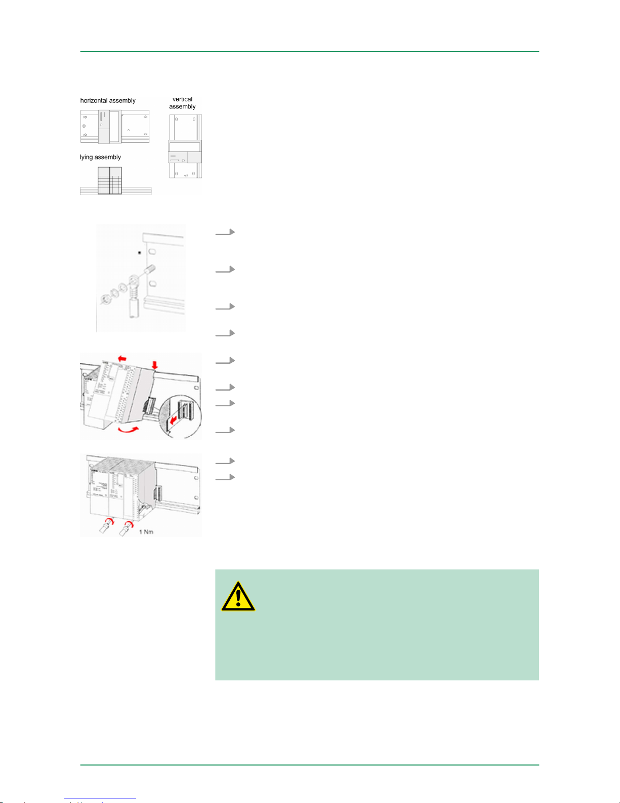
Please regard the allowed environment temperatures:
n horizontal assembly: from 0 to 60°C
n vertical assembly: from 0 to 50°C
n lying assembly: from 0 to 55°C
1. Bolt the profile rail with the background (screw size: M6), so that
you still have minimum 65mm space above and 40mm below
the profile rail.
2. If the background is a grounded metal or device plate, please
look for a low-impedance connection between profile rail and
background.
3. Connect the profile rail with the protected earth conductor. For
this purpose there is a bolt with M6-thread.
4. The minimum cross-section of the cable to the protected earth
conductor has to be 10mm2.
5. Stick the power supply to the profile rail and pull it to the left side
to the grounding bolt of the profile rail.
6. Fix the power supply by screwing.
7. Take a backplane bus connector and click it at the CPU from the
backside like shown in the picture.
8. Stick the CPU to the profile rail right from the power supply and
pull it to the power supply.
9. Click the CPU downwards and bolt it like shown.
10. Repeat this procedure with the peripheral modules, by clicking a
backplane bus connector, stick the module right from the
modules you've already fixed, click it downwards and connect it
with the backplane bus connector of the last module and bolt it.
3.3
Cabling
CAUTION!
– The power supplies must be released before installa-
tion and repair tasks, i.e. before handling with the
power supply or with the cabling you must disconnect
current/voltage (pull plug, at fixed connection switch off
the concerning fuse)!
–
Installation and modifications only by properly trained
personnel!
Assembly possibilities
Approach
VIPA System 300SAssembly and installation guidelines
Cabling
HB140 | CPU-SC | 313-6CF13 | GB | 15-50 18
Page 19
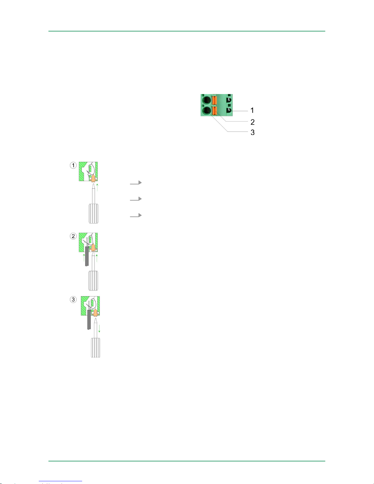
For the cabling of power supply of a CPU, a green plug with CageClamp technology is deployed. The connection clamp is realized as
plug that may be clipped off carefully if it is still cabled.
Here wires with a cross-section of 0.08mm2 to 2.5mm2 may be connected. You can use flexible wires without end case as well as stiff
wires.
1 Test point for 2mm test tip
2 Locking (orange) for screwdriver
3 Round opening for wires
The picture on the left side shows the cabling step by step from top
view.
1. For cabling you push the locking vertical to the inside with a
suiting screwdriver and hold the screwdriver in this position.
2. Insert the de-isolated wire into the round opening. You may use
wires with a cross-section from 0.08mm2 to 2.5mm
2
3. By removing the screwdriver the wire is connected safely with
the plug connector via a spring.
In the following the cabling of the two variants are shown.
CageClamp technology
(green)
Front connectors of the
in-/output modules
VIPA System 300S Assembly and installation guidelines
Cabling
HB140 | CPU-SC | 313-6CF13 | GB | 15-50 19
Page 20
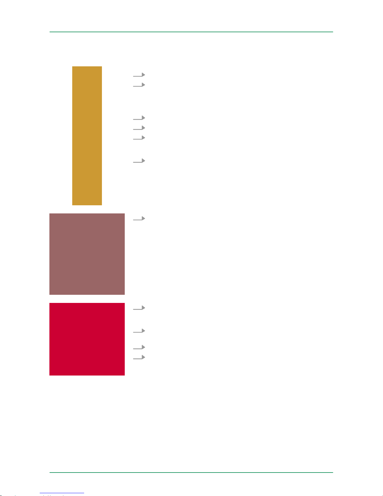
1. Open the front flap of your I/O module.
2. Bring the front connector in cabling position.
For this you plug the front connector on the module until it locks.
In this position the front connector juts out of the module and
has no contact yet.
3. De-isolate your wires. If needed, use core end cases.
4. Thread the included cable binder into the front connector.
5. If you want to lead out your cables from the bottom of the
module, start with the cabling from bottom to top, res. from top
to bottom, if the cables should be led out at the top.
6. Bolt also the connection screws of not cabled screw clamps.
7. Fix the cable binder for the cable bundle.
8. Push the release key at the front connector on the upper side of
the module and at the same time push the front connector into
the module until it locks.
9. Now the front connector is electrically connected with your
module.
10. Close the front flap.
11. Fill out the labeling strip to mark the single channels and push
the strip into the front flap.
20pole screw connection 392-1AJ00
VIPA System 300SAssembly and installation guidelines
Cabling
HB140 | CPU-SC | 313-6CF13 | GB | 15-50 20
Page 21
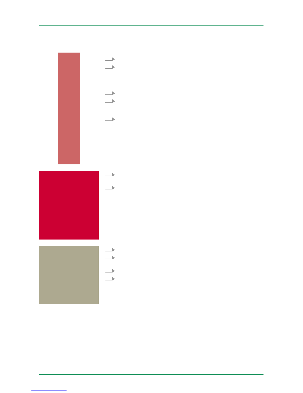
1. Open the front flap of your I/O module.
2. Bring the front connector in cabling position.
For this you plug the front connector on the module until it locks.
In this position the front connector juts out of the module and
has no contact yet.
3. De-isolate your wires. If needed, use core end cases.
4. If you want to lead out your cables from the bottom of the
module, start with the cabling from bottom to top, res. from top
to bottom, if the cables should be led out at the top.
5. Bolt also the connection screws of not cabled screw clamps.
6. Put the included cable binder around the cable bundle and the
front connector.
7. Fix the cable binder for the cable bundle.
8. Bolt the fixing screw of the front connector.
9. Now the front connector is electrically connected with your
module.
10. Close the front flap.
11. Fill out the labeling strip to mark the single channels and push
the strip into the front flap.
3.4
Installation guidelines
The installation guidelines contain information about the interference
free deployment of a PLC system. There is the description of the
ways, interference may occur in your PLC, how you can make sure
the electromagnetic compatibility (EMC), and how you manage the
isolation.
40pole screw connection 392-1AM00
General
VIPA System 300S Assembly and installation guidelines
Installation guidelines
HB140 | CPU-SC | 313-6CF13 | GB | 15-50 21
Page 22

Electromagnetic compatibility (EMC) means the ability of an electrical
device, to function error free in an electromagnetic environment
without being interfered respectively without interfering the environment.
The components of VIPA are developed for the deployment in industrial environments and meets high demands on the EMC. Nevertheless you should project an EMC planning before installing the components and take conceivable interference causes into account.
Electromagnetic interferences may interfere your control via different
ways:
n Electromagnetic fields (RF coupling)
n Magnetic fields with power frequency
n Bus system
n Power supply
n Protected earth conductor
Depending on the spreading medium (lead bound or lead free) and
the distance to the interference cause, interferences to your control
occur by means of different coupling mechanisms.
There are:
n galvanic coupling
n capacitive coupling
n inductive coupling
n radiant coupling
In the most times it is enough to take care of some elementary rules
to guarantee the EMC. Please regard the following basic rules when
installing your PLC.
n Take care of a correct area-wide grounding of the inactive metal
parts when installing your components.
–
Install a central connection between the ground and the pro-
tected earth conductor system.
– Connect all inactive metal extensive and impedance-low.
– Please try not to use aluminium parts. Aluminium is easily oxi-
dizing and is therefore less suitable for grounding.
n When cabling, take care of the correct line routing.
– Organize your cabling in line groups (high voltage, current
supply, signal and data lines).
– Always lay your high voltage lines and signal respectively data
lines in separate channels or bundles.
– Route the signal and data lines as near as possible beside
ground areas (e.g. suspension bars, metal rails, tin cabinet).
n Proof the correct fixing of the lead isolation.
– Data lines must be laid isolated.
– Analog lines must be laid isolated. When transmitting signals
with small amplitudes the one sided laying of the isolation may
be favourable.
– Lay the line isolation extensively on an isolation/protected
earth conductor rail directly after the cabinet entry and fix the
isolation with cable clamps.
– Make sure that the isolation/protected earth conductor rail is
connected impedance-low with the cabinet.
– Use metallic or metallised plug cases for isolated data lines.
What does EMC mean?
Possible interference
causes
Basic rules for EMC
VIPA System 300SAssembly and installation guidelines
Installation guidelines
HB140 | CPU-SC | 313-6CF13 | GB | 15-50 22
Page 23

n In special use cases you should appoint special EMC actions.
–
Consider to wire all inductivities with erase links.
– Please consider luminescent lamps can influence signal lines.
n Create a homogeneous reference potential and ground all elec-
trical operating supplies when possible.
– Please take care for the targeted employment of the grounding
actions. The grounding of the PLC serves for protection and
functionality activity.
– Connect installation parts and cabinets with your PLC in star
topology with the isolation/protected earth conductor system.
So you avoid ground loops.
– If there are potential differences between installation parts and
cabinets, lay sufficiently dimensioned potential compensation
lines.
Electrical, magnetically and electromagnetic interference fields are
weakened by means of an isolation, one talks of absorption. Via the
isolation rail, that is connected conductive with the rack, interference
currents are shunt via cable isolation to the ground. Here you have to
make sure, that the connection to the protected earth conductor is
impedance-low, because otherwise the interference currents may
appear as interference cause.
When isolating cables you have to regard the following:
n If possible, use only cables with isolation tangle.
n The hiding power of the isolation should be higher than 80%.
n Normally you should always lay the isolation of cables on both
sides. Only by means of the both-sided connection of the isolation
you achieve high quality interference suppression in the higher
frequency area. Only as exception you may also lay the isolation
one-sided. Then you only achieve the absorption of the lower frequencies. A one-sided isolation connection may be convenient, if:
–
the conduction of a potential compensating line is not possible.
– analog signals (some mV respectively µA) are transferred.
– foil isolations (static isolations) are used.
n With data lines always use metallic or metallised plugs for serial
couplings. Fix the isolation of the data line at the plug rack. Do not
lay the isolation on the PIN 1 of the plug bar!
n At stationary operation it is convenient to strip the insulated cable
interruption free and lay it on the isolation/protected earth conductor line.
n To fix the isolation tangles use cable clamps out of metal. The
clamps must clasp the isolation extensively and have well contact.
n Lay the isolation on an isolation rail directly after the entry of the
cable in the cabinet. Lead the isolation further on to your PLC and
don't lay it on there again!
CAUTION!
Please regard at installation!
At potential differences between the grounding points,
there may be a compensation current via the isolation connected at both sides.
Remedy: Potential compensation line
Isolation of conductors
VIPA System 300S Assembly and installation guidelines
Installation guidelines
HB140 | CPU-SC | 313-6CF13 | GB | 15-50 23
Page 24
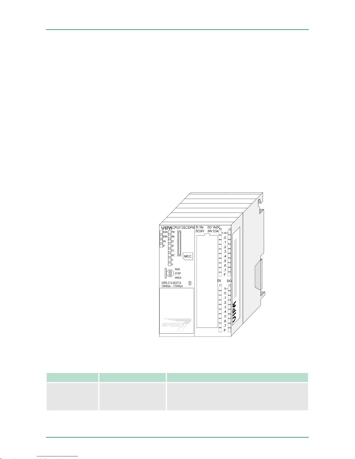
4 Hardware description
4.1 Properties
n SPEED7 technology integrated
n 128kbyte work memory integrated (64kbyte code, 64kbyte data)
n Work memory expandable to max. 512Mbyte (256kbyte code,
256kbyte data)
n 512kbyte load memory
n PROFIBUS DP master integrated supported DP-V0, DP-V1
n RS485 interface for PtP communication
n Ethernet PG/OP interface integrated
n MPI interface
n MCC slot for external memory cards (lockable)
n Status LEDs for operating state and diagnostics
n Real-time clock battery buffered
n Digital I/Os: DI 16xDC24V / DO 16xDC24V, 0.5A
n 3 channels for counter, frequency measurement and pulse width
modulation
n I/O address range digital/analog 1024byte
n 512 timer / 512 counter / 8192 flag byte
Type Order number Description
313SC 313-6CF13 MPI interface, Card slot, Real-time clock, Ethernet
interface for PG/OP, PB-DP master / PtP interface,
DI 16xDC24V / DO 16xDC 24V, 0.5A, 3 channels
technological function
CPU 313-6CF13
Ordering data
VIPA System 300SHardware description
Properties
HB140 | CPU-SC | 313-6CF13 | GB | 15-50 24
Page 25
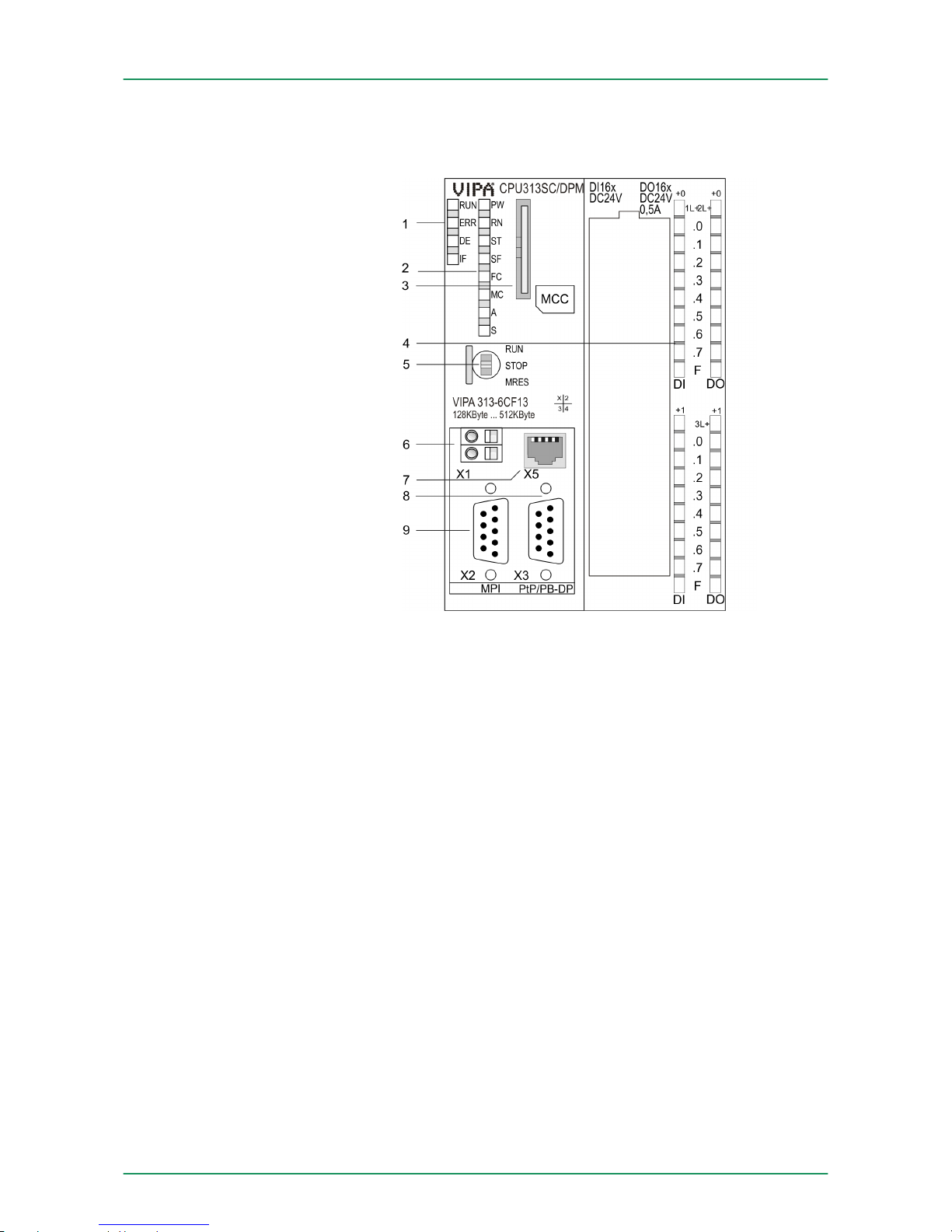
4.2 Structure
4.2.1
General
1 LEDs of the integrated PROFIBUS DP master
2 LEDs of the CPU part
3 Storage media slot (lockable)
4 LEDs of the I/O part
5 Operating mode switch CPU
6 Slot for DC 24V power supply
7 Twisted pair interface for Ethernet PG/OP channel
8 PtP/PROFIBUS DP interface
9 MPI interface
The components 6 - 9 are under the front flap!
CPU 313-6CF13
VIPA System 300S Hardware description
Structure > General
HB140 | CPU-SC | 313-6CF13 | GB | 15-50 25
Page 26
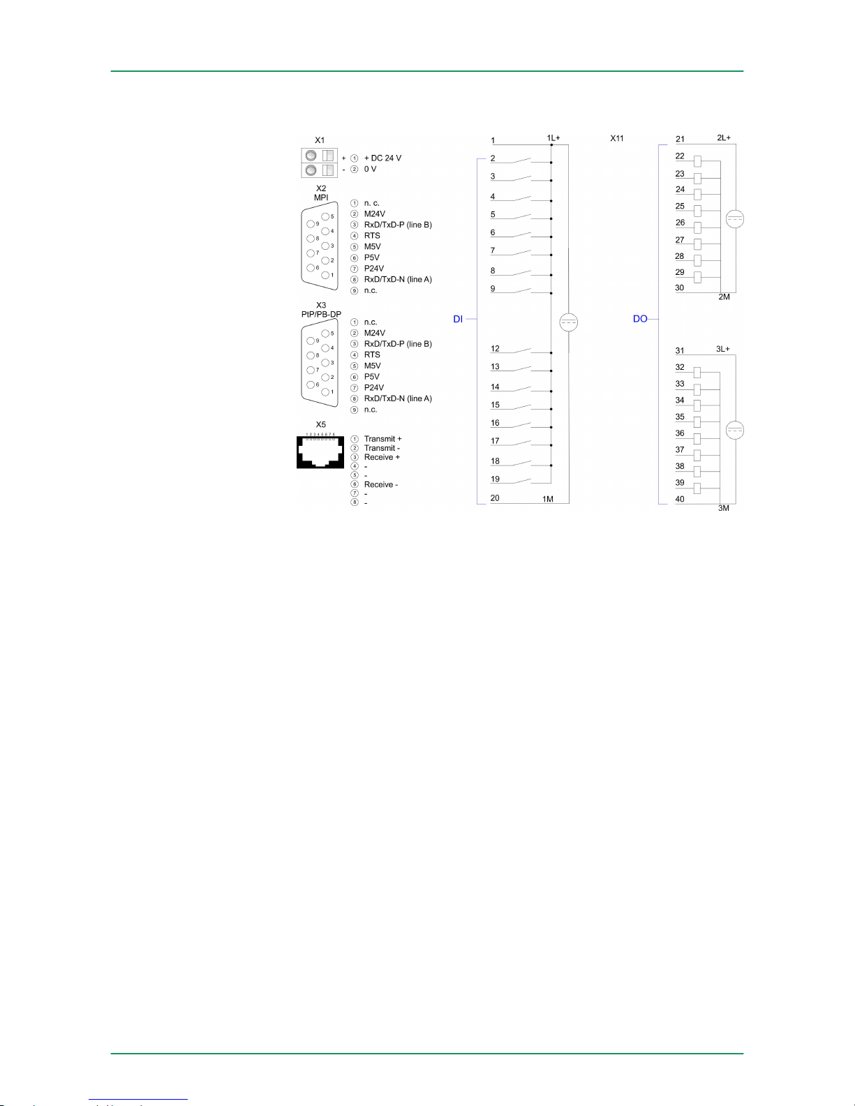
4.2.2 Interfaces
The CPU has an integrated power supply:
n The power supply has to be provided with DC 24V. For this serves
the double DC 24V slot, that is underneath the flap.
n Via the power supply not only the internal electronic is provided
with voltage, but by means of the backplane bus also the connected modules.
n The power supply is protected against polarity inversion and over-
current.
n The internal electronic is galvanically connected with the supply
voltage.
9pin SubD jack:
n The MPI interface serves for the connection between program-
ming unit and CPU.
n By means of this the project engineering and programming hap-
pens.
n MPI serves for communication between several CPUs or between
HMIs and CPU.
n Standard setting is MPI Address 2.
9pin SubD jack:
Per default, the RS485 interface X3 of the CPU is used for the
PROFIBUS DP master.
The functionality of this interface may be configured at the virtual
SPEED-Bus by means of the parameter "Function RS485 X3" of the
hardware configuration.
X1: Power supply
X2: MPI interface
X3: PtP/PB-DP interface
VIPA System 300SHardware description
Structure > Interfaces
HB140 | CPU-SC | 313-6CF13 | GB | 15-50 26
Page 27

n PROFIBUS functionality
–
Using the PROFIBUS functionality the integrated PROFIBUS
DP master is connected to PROFIBUS via RS485 interface.
– At master operation there is access to up to 124 DP slaves.
– For this the project engineering happens in the hardware con-
figurator from Siemens.
– Please regard there may be a delimitation of the maximum
number of configurable DP slaves by the use of the Siemens
SIMATIC manager.
n PtP functionality
–
Using the PtP functionality the RS485 interface is allowed to
connect via serial point-to-point connection to different source
res. target systems.
– Here the following protocols are supported: ASCII, STX/ETX,
3964R, USS and Modbus-Master (ASCII, RTU).
– The PtP communication is configured during run-time by
means of the SFC 216 (SER_CFG). The communication hap-
pens by means of the SFC 217 (SER_SND) and SFC 218
(SER_RCV).
You can only use one interface with PtP respectively
PROFIBUS functionality.
8pin RJ45 jack:
n The RJ45 jack serves the interface to the Ethernet PG/OP
channel.
n This interface allows you to program res. remote control your
CPU, to access the internal web site or to connect a visualization.
n Configurable connections are not possible.
n For online access to the CPU via Ethernet PG/OP channel valid
IP address parameters have to be assigned to this.
X5: Ethernet PG/OP
channel
VIPA System 300S Hardware description
Structure > Interfaces
HB140 | CPU-SC | 313-6CF13 | GB | 15-50 27
Page 28
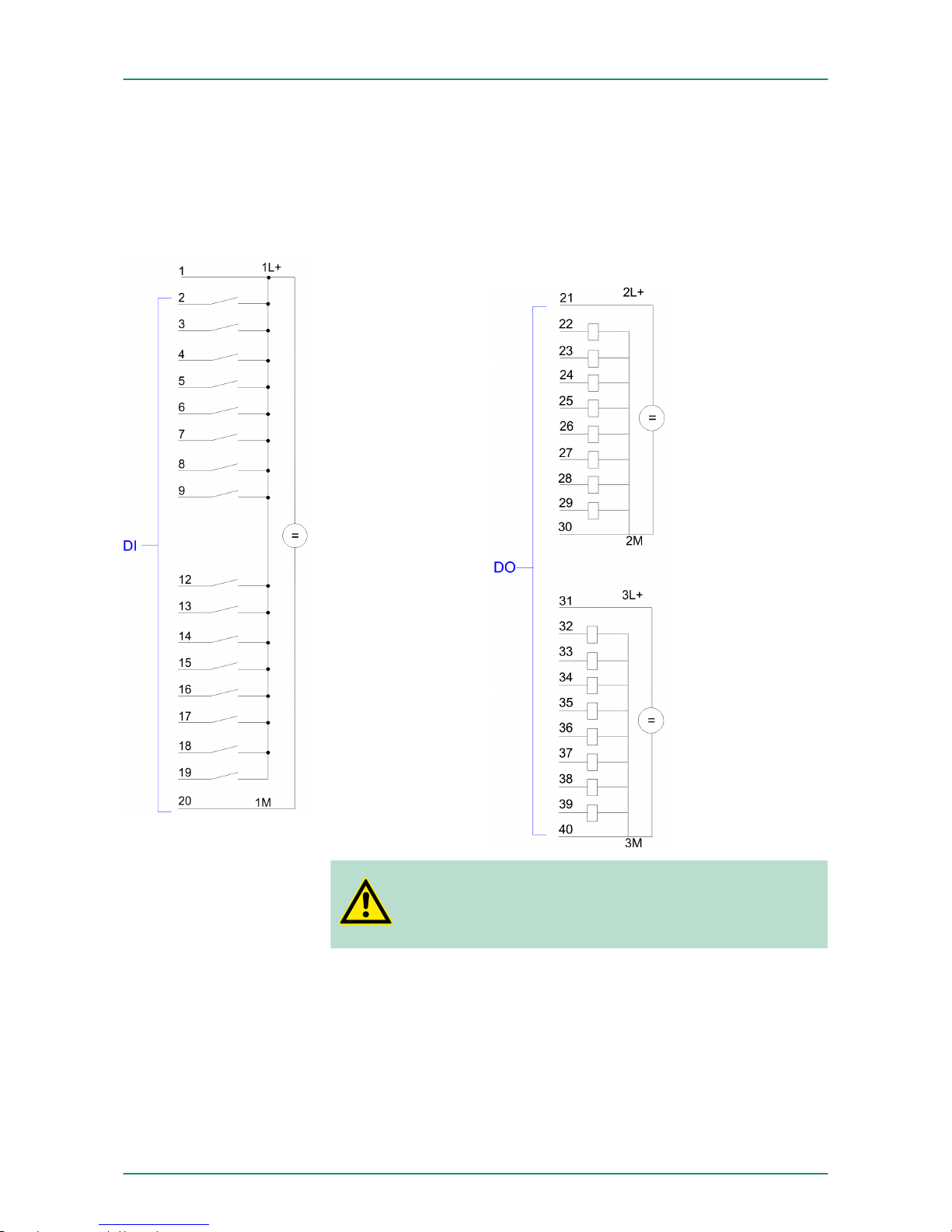
4.2.3 In-/Output area CPU 313-6CF13
The CPU 313-6CF13 has the following digital in- and output ranges
integrated in one casing:
n Digital Input: 16xDC 24V, with interrupt capability
n Digital Output: 16xDC 24V, 0.5A
n Technological functions: 3 channels
X11:
CAUTION!
Please regard that the voltage at an output channel is
always £ the supply voltage connected to L+.
Overview
VIPA System 300SHardware description
Structure > In-/Output area CPU 313-6CF13
HB140 | CPU-SC | 313-6CF13 | GB | 15-50 28
Page 29
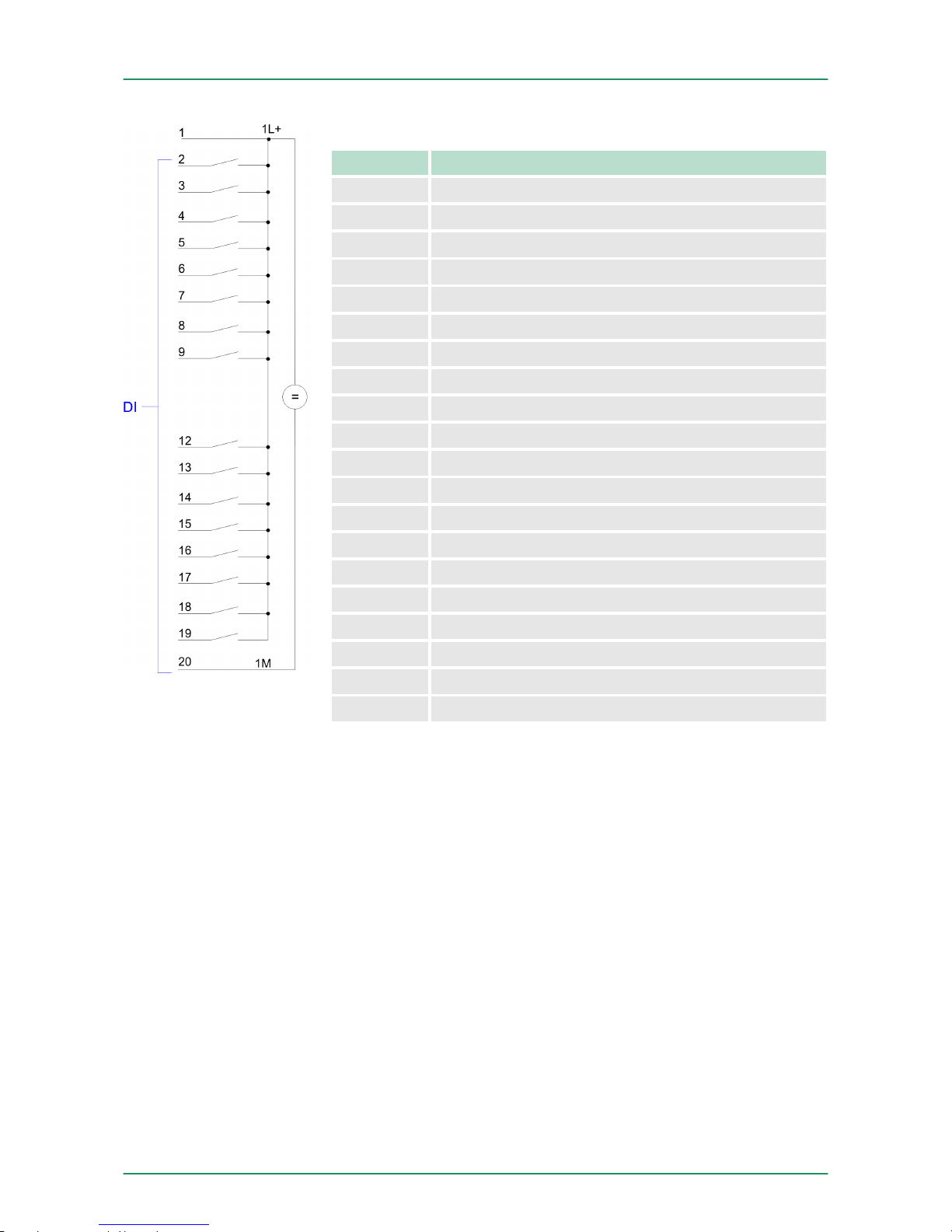
Pin assignment X11: DI
Pin Assignment
1 1L+ Power supply +DC 24V
2 I+0.0 / Channel 0 (A) / Pulse
3 I+0.1 / Channel 0 (B) / Direction
4 I+0.2 / Channel 0 HW gate
5 I+0.3 / Channel 1 (A) / Pulse
6 I+0.4 / Channel 1 (B) / Direction
7 I+0.5 / Channel 1 HW gate
8 I+0.6 / Channel 2 (A) / Pulse
9 I+0.7 / Channel 2 (B) / Direction
10 not used
11 not used
12 I+1.0 / Channel 2 HW gate
13 I+1.1
14 I+1.2
15 I+1.3
16 I+1.4 / Channel 0 Latch
17 I+1.5 / Channel 1 Latch
18 I+1.6 / Channel 2 Latch
19 I+1.7
20 Ground 1M DI
VIPA System 300S Hardware description
Structure > In-/Output area CPU 313-6CF13
HB140 | CPU-SC | 313-6CF13 | GB | 15-50 29
Page 30
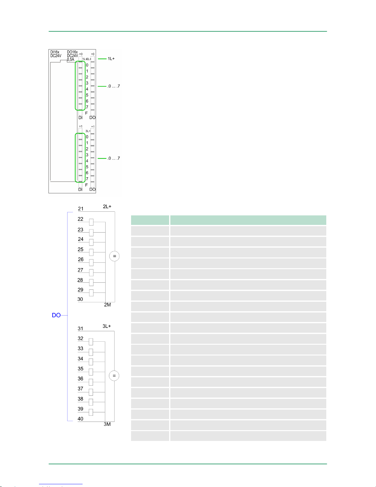
Status indication X11: DI
n 1L+
–
LED (green)
Supply voltage available for DI
n .0 ... .7
– LEDs (green)
I+0.0 ... I+0.7
I+1.0 ... I+1.7
Starting with ca. 15V the signal "1" at the input is recognized
and the according LED is activated
Pin assignment X11: DO
Pin Assignment
21 2L+ Power supply +DC 24V
22 O+0.0 / Channel 0 Output
23 O+0.1 / Channel 1 Output
24 Q+0.2 / Channel 2 Output
25 Q+0.3
26 Q+0.4
27 Q+0.5
28 Q+0.6
29 Q+0.7
30 Ground 2M DO
31 3L+ Power supply +DC 24V
32 Q+1.0
33 Q+1.1
34 Q+1.2
35 Q+1.3
36 Q+1.4
37 Q+1.5
38 Q+1.6
39 Q+1.7
40 Ground 3M DO
VIPA System 300SHardware description
Structure > In-/Output area CPU 313-6CF13
HB140 | CPU-SC | 313-6CF13 | GB | 15-50 30
Page 31
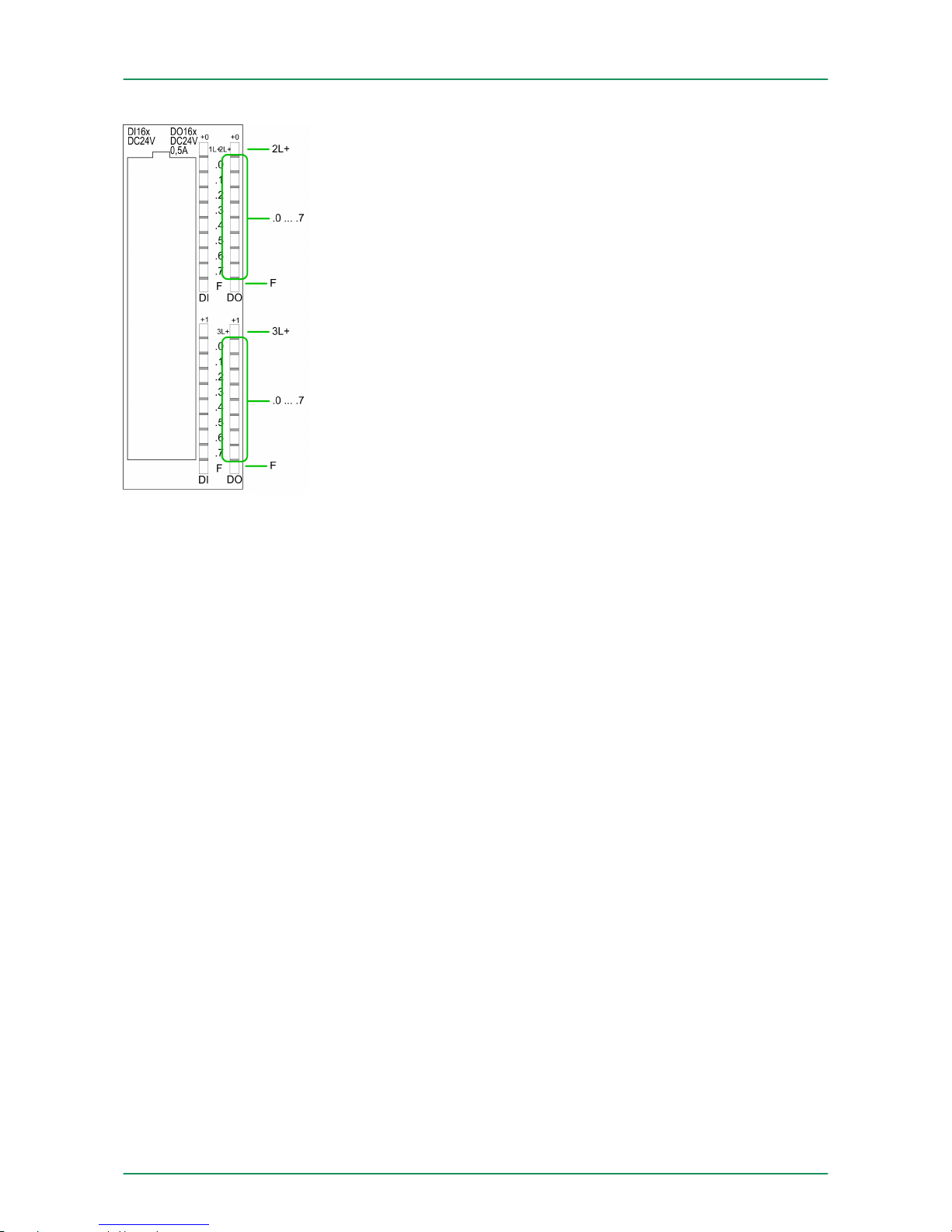
Status indication X11: DO
n 2L+, 3L+
–
LED (green)
Supply voltage available for DO
n .0 ... .7
– LEDs (green)
Q+0.0 ... Q+0.7
Q+1.0 ... Q+1.7
The according LED is on at active output
n F
– LED (red)
Overload or short circuit error
4.2.4 Memory management
The CPU has an integrated memory. Information about the capacity
of the memory may be found at the front of the CPU. The memory is
divided into the following parts:
n Load memory 512kbyte
n Code memory (50% of the work memory)
n Data memory (50% of the work memory)
n Work memory 128kbyte
–
There is the possibility to extend the work memory to its max-
imum printed capacity 512kbyte by means of a MCC memory
extension card.
4.2.5 Storage media slot
n As external storage medium for applications and firmware you
may use a MMC storage module (Multimedia card).
n The VIPA storage media are pre-formatted with the PC format
FAT16 and can be accessed via a card reader.
n After PowerON respectively an overall reset the CPU checks, if
there is a storage medium with data valid for the CPU.
n Push the memory card into the slot until it snaps in leaded by a
spring mechanism. This ensures contacting.
n By sliding down the sliding mechanism, a just installed memory
card can be protected against drop out.
n To remove, slide the sliding mechanism up again and push the
storage media against the spring pressure until it is unlocked with
a click.
Memory
VIPA System 300S Hardware description
Structure > Storage media slot
HB140 | CPU-SC | 313-6CF13 | GB | 15-50 31
Page 32
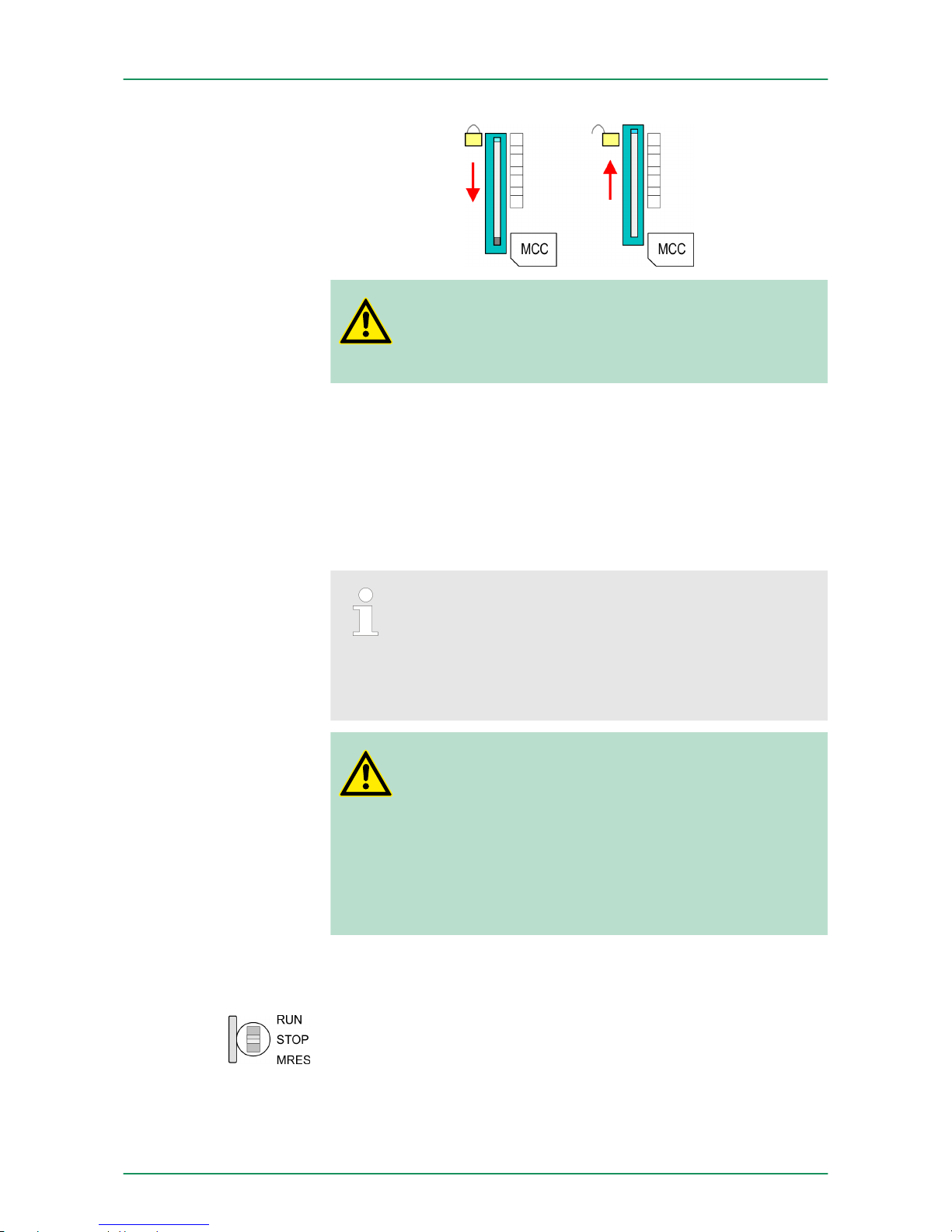
CAUTION!
If the media was already unlocked by the spring mechanism, with shifting the sliding mechanism, a just installed
memory card can jump out of the slot!
4.2.6 Battery backup for clock and RAM
A rechargeable battery is installed on every CPU to safeguard the
contents of the RAM when power is removed. This battery is also
used to buffer the internal clock. The rechargeable battery is maintained by a charging circuit that receives its power from the internal
power supply and that maintain the clock and RAM for a max. period
of 30 days.
– Please connect the CPU at least for 24 hours to the
power supply, so that the internal accumulator/battery
is loaded accordingly.
– Please note that in case of repeated discharge cycles
(charging/buffering) can reduce the buffer time continuously. Only after a charging time of 24 hours there is a
buffer for max. 30 days.
CAUTION!
– After a power reset and with an empty battery the CPU
starts with a BAT error and executes an overall reset.
The loading procedure is not influenced by the BAT
error.
–
The BAT error can be deleted again, if once during
power cycle the time between switching on and off the
power supply is at least 30sec. and the battery is fully
loaded. Otherwise with a short power cycle the BAT
error still exists and an overall reset is executed.
4.2.7 Operating mode switch
n With the operating mode switch you may switch the CPU between
STOP and RUN.
n During the transition from STOP to RUN the operating mode
START-UP is driven by the CPU.
n Placing the switch to MRES (Memory Reset), you request an
overall reset with following load from MMC, if a project there
exists.
VIPA System 300SHardware description
Structure > Operating mode switch
HB140 | CPU-SC | 313-6CF13 | GB | 15-50 32
Page 33
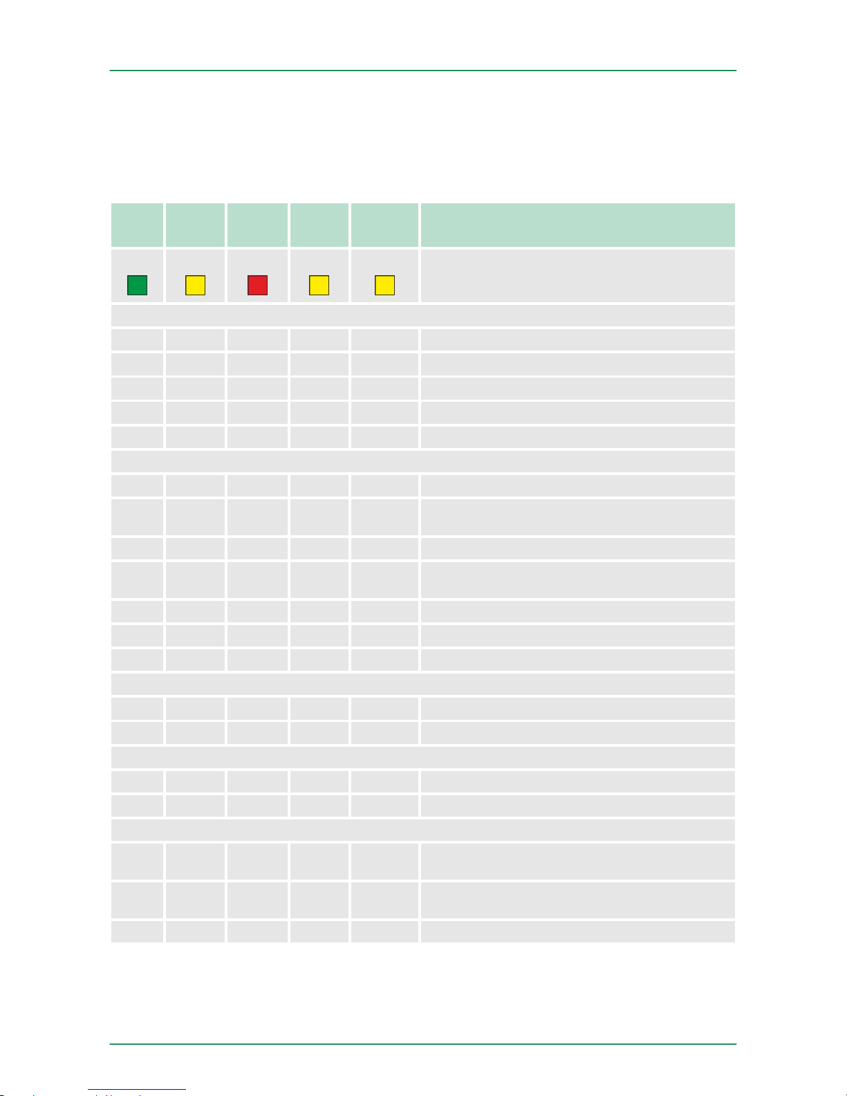
4.2.8 LEDs
As soon as the CPU is supplied with 5V, the green PW-LED (Power)
is on.
RN
(RUN)ST(STOP)SF(SFAIL)FC(FRCE)MC(MMC)
Meaning
green yellow red yellow yellow
Boot-up after PowerON
● BB* ● ● ● * Blinking with 10Hz: Firmware is loaded.
● ● ● ● ● Initialization: Phase 1
● ● ● ● ○ Initialization: Phase 2
● ● ● ○ ○ Initialization: Phase 3
○ ● ● ○ ○ Initialization: Phase 4
Operation
○ ● X X X CPU is in STOP state.
BB ○ X X X CPU is in start-up state, the RUN LED blinks during
operating OB100 at least for 3s.
● ○ ○ X X CPU is in state RUN without error.
X X ● X X There is a system fault. More information may be
found in the diagnostics buffer of the CPU.
X X X ● X Variables are forced.
X X X X ● Access to the memory card.
X BB* ○ ○ ○ * Blinking with 10Hz: Configuration is loaded.
Overall reset
○ BB X X X Overall reset is requested.
○ BB* X X X * Blinking with 5Hz: Overall reset is executed.
Factory reset
● ● ○ ○ ○ Factory reset is executed.
○ ● ● ● ● Factory reset finished without error.
Firmware update
○ ● BB BB ● The alternate blinking indicates that there is new
firmware on the memory card.
○ ○ BB BB ● The alternate blinking indicates that a firmware
update is executed.
○ ● ● ● ● Firmware update finished without error.
LEDs CPU
VIPA System 300S Hardware description
Structure > LEDs
HB140 | CPU-SC | 313-6CF13 | GB | 15-50 33
Page 34
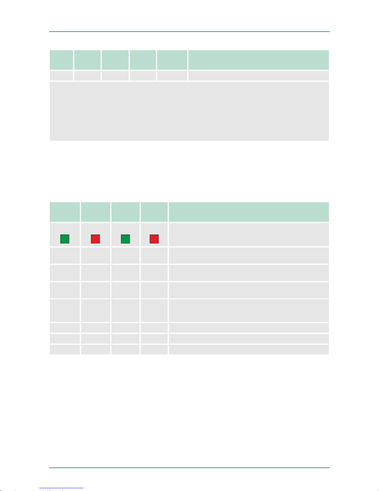
RN
(RUN)ST(STOP)SF(SFAIL)FC(FRCE)MC(MMC)
Meaning
○ BB* BB* BB* BB* * Blinking with 10Hz: Error during Firmware update.
on: ● | off: ○ | blinking (2Hz): BB | not relevant: X
LEDs Ethernet PG/OP channel L/A, S
The green L/A-LED (Link/Activity) indicates the physical connection of the Ethernet PG/OP channel to
Ethernet. Irregular flashing of the L/A-LED indicates communication of the Ethernet PG/OP channel via
Ethernet.
If the green S-LED (Speed) is on, the Ethernet PG/OP has a communication speed of 100MBit/s otherwise
10MBit/s.
Dependent on the mode of operation the LEDs show information
about the state of operation of the PROFIBUS part according to the
following pattern:
Master operation
RN
(RUN)
ER
(ERR)
DE IF Meaning
green red green red
○ ○ ○ ○ Master has no project, this means the interface is
deactivated respectively PtP is active.
● ○ ○ ○ Master has bus parameters and is in RUN without
slaves.
● ○ BB ○ Master is in "clear" state (safety state). The inputs of
the slaves may be read. The outputs are disabled.
● ○ ● ○ Master is in "operate" state, this means data exchange
between master and slaves. The outputs may be
accessed.
● ● ● ○ CPU is in RUN, at least 1 slave is missing.
● ● BB ○ CPU is in STOP, at least 1 slave is missing.
○ ○ ○ ● Initialization error at faulty parametrization.
LEDs PROFIBUS/PtP
interface X3
VIPA System 300SHardware description
Structure > LEDs
HB140 | CPU-SC | 313-6CF13 | GB | 15-50 34
Page 35
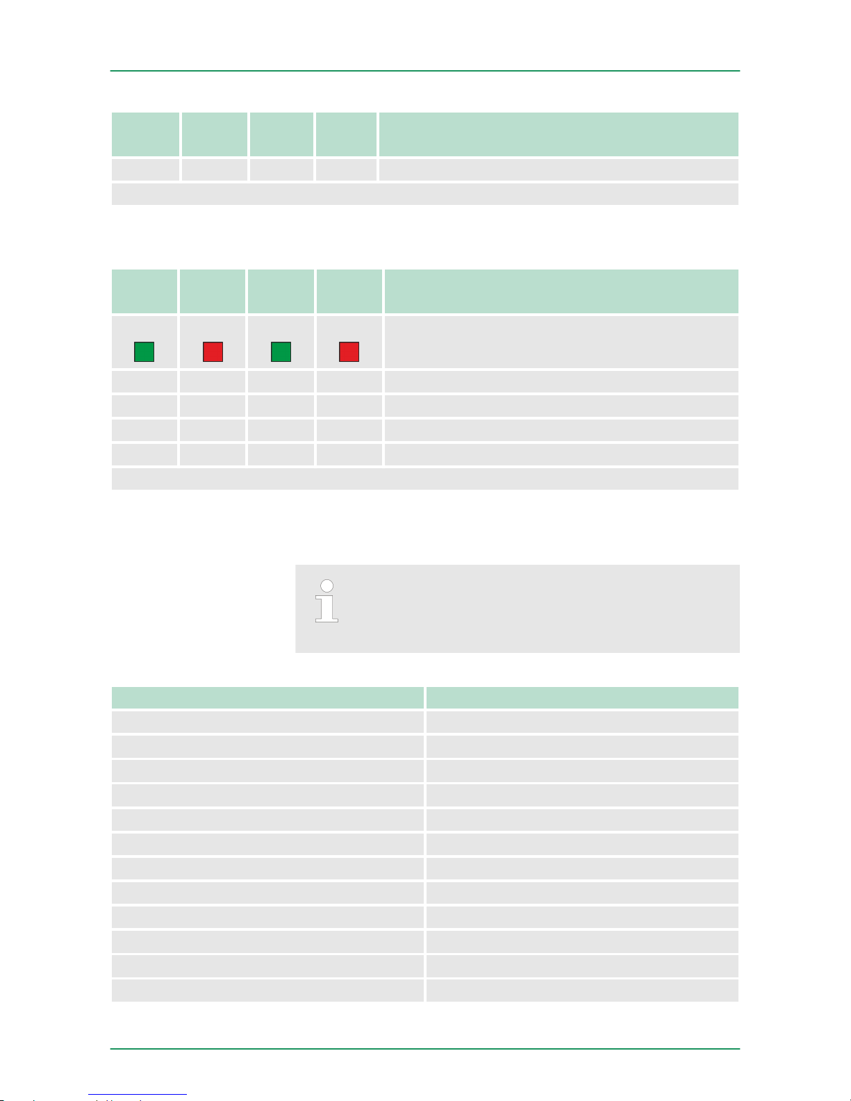
RN
(RUN)
ER
(ERR)
DE IF Meaning
○ ● ○ ● Waiting state for start command from CPU.
on: ● | off: ○ | blinking (2Hz): BB
Slave operation
RN
(RUN)
ER
(ERR)
DE IF Meaning
green red green red
○ ○ ○ ○ Slave has no project respectively PtP is active.
BB ○ ○ ○ Slave is without master.
BB* ○ BB* ○ * Alternate flashing at configuration faults.
● ○ ● ○ Slave exchanges data between master.
on: ● | off: ○ | blinking (2Hz): BB
4.3 Technical data
Please consider with the configuration with the Siemens
TIA Portal the number of timer and counters is limited to
the maximum possible number of the corresponding Siemens CPU.
Order no. 313-6CF13
Type CPU 313SC/DPM
SPEED-Bus -
Technical data power supply
Power supply (rated value) DC 24 V
Power supply (permitted range) DC 20.4...28.8 V
Reverse polarity protection
ü
Current consumption (no-load operation) 200 mA
Current consumption (rated value) 900 mA
Inrush current 11 A
I²t 0.7 A²s
Max. current drain at backplane bus 3 A
Power loss 14 W
VIPA System 300S Hardware description
Technical data
HB140 | CPU-SC | 313-6CF13 | GB | 15-50 35
Page 36

Order no. 313-6CF13
Technical data digital inputs
Number of inputs 16
Cable length, shielded 1000 m
Cable length, unshielded 600 m
Rated load voltage DC 24 V
Reverse polarity protection of rated load
voltage
ü
Current consumption from load voltage L+
(without load)
70 mA
Rated value DC 24 V
Input voltage for signal "0" DC 0...5 V
Input voltage for signal "1" DC 15...28.8 V
Input voltage hysteresis -
Frequency range -
Input resistance -
Input current for signal "1" 6 mA
Connection of Two-Wire-BEROs possible
ü
Max. permissible BERO quiescent current 1.5 mA
Input delay of "0" to "1" 0.1 / 0.35 ms
Input delay of "1" to "0" 0.1 / 0.35 ms
Number of simultaneously utilizable inputs horizontal configuration
16
Number of simultaneously utilizable inputs vertical configuration
16
Input characteristic curve IEC 61131-2, type 1
Initial data size 2 Byte
Technical data digital outputs
Number of outputs 16
Cable length, shielded 1000 m
Cable length, unshielded 600 m
Rated load voltage DC 24 V
Reverse polarity protection of rated load
voltage
-
Current consumption from load voltage L+
(without load)
100 mA
Total current per group, horizontal configuration, 40°C
3 A
Total current per group, horizontal configuration, 60°C
2 A
VIPA System 300SHardware description
Technical data
HB140 | CPU-SC | 313-6CF13 | GB | 15-50 36
Page 37

Order no. 313-6CF13
Total current per group, vertical configuration 2 A
Output voltage signal "1" at min. current L+ (-0.8 V)
Output voltage signal "1" at max. current L+ (-0.8 V)
Output current at signal "1", rated value 0.5 A
Output current, permitted range to 40°C 5 mA to 0.6 A
Output current, permitted range to 60°C 5 mA to 0.6 A
Output current at signal "0" max. (residual current)
0.5 mA
Output delay of "0" to "1" 100 µs
Output delay of "1" to "0" 100 µs
Minimum load current -
Lamp load 5 W
Parallel switching of outputs for redundant control of a load
possible
Parallel switching of outputs for increased
power
not possible
Actuation of digital input
ü
Switching frequency with resistive load max. 2.5 kHz
Switching frequency with inductive load max. 0.5 Hz
Switching frequency on lamp load max. 2.5 kHz
Internal limitation of inductive shut-off voltage L+ (-52 V)
Short-circuit protection of output yes, electronic
Trigger level 1 A
Number of operating cycle of relay outputs -
Switching capacity of contacts -
Output data size 2 Byte
Technical data analog inputs
Number of inputs -
Cable length, shielded -
Rated load voltage -
Reverse polarity protection of rated load
voltage
-
Current consumption from load voltage L+
(without load)
-
Voltage inputs -
Min. input resistance (voltage range) -
Input voltage ranges -
Operational limit of voltage ranges -
VIPA System 300S Hardware description
Technical data
HB140 | CPU-SC | 313-6CF13 | GB | 15-50 37
Page 38

Order no. 313-6CF13
Operational limit of voltage ranges with SFU -
Basic error limit voltage ranges -
Basic error limit voltage ranges with SFU -
Destruction limit current -
Current inputs -
Max. input resistance (current range) -
Input current ranges -
Operational limit of current ranges -
Operational limit of current ranges with SFU -
Basic error limit current ranges -
Radical error limit current ranges with SFU -
Destruction limit current inputs (electrical current)
-
Destruction limit current inputs (voltage) -
Resistance inputs -
Resistance ranges -
Operational limit of resistor ranges -
Operational limit of resistor ranges with SFU -
Basic error limit -
Basic error limit with SFU -
Destruction limit resistance inputs -
Resistance thermometer inputs -
Resistance thermometer ranges -
Operational limit of resistance thermometer
ranges
-
Operational limit of resistance thermometer
ranges with SFU
-
Basic error limit thermoresistor ranges -
Basic error limit thermoresistor ranges with
SFU
-
Destruction limit resistance thermometer inputs -
Thermocouple inputs -
Thermocouple ranges -
Operational limit of thermocouple ranges -
Operational limit of thermocouple ranges with
SFU
-
Basic error limit thermoelement ranges -
VIPA System 300SHardware description
Technical data
HB140 | CPU-SC | 313-6CF13 | GB | 15-50 38
Page 39

Order no. 313-6CF13
Basic error limit thermoelement ranges with
SFU
-
Destruction limit thermocouple inputs -
Programmable temperature compensation -
External temperature compensation -
Internal temperature compensation -
Technical unit of temperature measurement -
Resolution in bit -
Measurement principle -
Basic conversion time -
Noise suppression for frequency -
Initial data size -
Technical data analog outputs
Number of outputs -
Cable length, shielded -
Rated load voltage -
Reverse polarity protection of rated load
voltage
-
Current consumption from load voltage L+
(without load)
-
Voltage output short-circuit protection -
Voltage outputs -
Min. load resistance (voltage range) -
Max. capacitive load (current range) -
Max. inductive load (current range) -
Output voltage ranges -
Operational limit of voltage ranges -
Basic error limit voltage ranges with SFU -
Destruction limit against external applied
voltage
-
Current outputs -
Max. in load resistance (current range) -
Max. inductive load (current range) -
Typ. open circuit voltage current output -
Output current ranges -
Operational limit of current ranges -
Radical error limit current ranges with SFU -
VIPA System 300S Hardware description
Technical data
HB140 | CPU-SC | 313-6CF13 | GB | 15-50 39
Page 40

Order no. 313-6CF13
Destruction limit against external applied
voltage
-
Settling time for ohmic load -
Settling time for capacitive load -
Settling time for inductive load -
Resolution in bit -
Conversion time -
Substitute value can be applied -
Output data size -
Technical data counters
Number of counters 3
Counter width 32 Bit
Maximum input frequency 30 kHz
Maximum count frequency 30 kHz
Mode incremental encoder
ü
Mode pulse / direction
ü
Mode pulse
ü
Mode frequency counter
ü
Mode period measurement
ü
Gate input available
ü
Latch input available
ü
Reset input available -
Counter output available
ü
Load and working memory
Load memory, integrated 512 KB
Load memory, maximum 512 KB
Work memory, integrated 128 KB
Work memory, maximal 512 KB
Memory divided in 50% program / 50% data
ü
Memory card slot MMC-Card with max. 1 GB
Hardware configuration
Racks, max. 4
Modules per rack, max. 8
Number of integrated DP master 1
Number of DP master via CP 4
Operable function modules 8
VIPA System 300SHardware description
Technical data
HB140 | CPU-SC | 313-6CF13 | GB | 15-50 40
Page 41

Order no. 313-6CF13
Operable communication modules PtP 8
Operable communication modules LAN 8
Status information, alarms, diagnostics
Status display yes
Interrupts yes
Process alarm yes
Diagnostic interrupt yes
Diagnostic functions no
Diagnostics information read-out possible
Supply voltage display green LED
Group error display red SF LED
Channel error display red LED per group
Isolation
Between channels
ü
Between channels of groups to 16
Between channels and backplane bus
ü
Between channels and power supply -
Max. potential difference between circuits DC 75 V/ AC 50 V
Max. potential difference between inputs (Ucm) -
Max. potential difference between Mana and
Mintern (Uiso)
-
Max. potential difference between inputs and
Mana (Ucm)
-
Max. potential difference between inputs and
Mintern (Uiso)
-
Max. potential difference between Mintern and
outputs
-
Insulation tested with DC 500 V
Command processing times
Bit instructions, min. 0.02 µs
Word instruction, min. 0.02 µs
Double integer arithmetic, min. 0.02 µs
Floating-point arithmetic, min. 0.12 µs
Timers/Counters and their retentive characteristics
Number of S7 counters 512
Number of S7 times 512
Data range and retentive characteristic
VIPA System 300S Hardware description
Technical data
HB140 | CPU-SC | 313-6CF13 | GB | 15-50 41
Page 42

Order no. 313-6CF13
Number of flags 8192 Byte
Number of data blocks 4095
Max. data blocks size 64 KB
Max. local data size per execution level 510 Byte
Blocks
Number of OBs 15
Number of FBs 2048
Number of FCs 2048
Maximum nesting depth per priority class 8
Maximum nesting depth additional within an
error OB
4
Time
Real-time clock buffered
ü
Clock buffered period (min.) 6 w
Accuracy (max. deviation per day) 10 s
Number of operating hours counter 8
Clock synchronization
ü
Synchronization via MPI Master/Slave
Synchronization via Ethernet (NTP) no
Address areas (I/O)
Input I/O address area 1024 Byte
Output I/O address area 1024 Byte
Input process image maximal 128 Byte
Output process image maximal 128 Byte
Digital inputs 8064
Digital outputs 8064
Digital inputs central 1008
Digital outputs central 1008
Integrated digital inputs 16
Integrated digital outputs 16
Analog inputs 503
Analog outputs 503
Analog inputs, central 248
Analog outputs, central 248
Integrated analog inputs 0
Integrated analog outputs 0
VIPA System 300SHardware description
Technical data
HB140 | CPU-SC | 313-6CF13 | GB | 15-50 42
Page 43

Order no. 313-6CF13
Communication functions
PG/OP channel
ü
Global data communication
ü
Number of GD circuits, max. 4
Size of GD packets, max. 22 Byte
S7 basic communication
ü
S7 basic communication, user data per job 76 Byte
S7 communication
ü
S7 communication as server
ü
S7 communication as client -
S7 communication, user data per job 160 Byte
Number of connections, max. 32
PWM data
PWM channels 3
PWM time basis 0.1ms/1ms
Period length 4...65535 / 1...65535 * timebase
Minimum pulse width 0...0.5*period
Type of output Highside with 1.1kOhm pulldown
Functionality Sub-D interfaces
Type X2
Type of interface RS485
Connector Sub-D, 9-pin, female
Electrically isolated -
MPI
ü
MP²I (MPI/RS232) -
DP master -
DP slave -
Point-to-point interface -
Type X3
Type of interface RS485
Connector Sub-D, 9-pin, female
Electrically isolated
ü
MPI -
MP²I (MPI/RS232) -
DP master yes
VIPA System 300S Hardware description
Technical data
HB140 | CPU-SC | 313-6CF13 | GB | 15-50 43
Page 44

Order no. 313-6CF13
DP slave yes
Point-to-point interface
ü
Functionality MPI
Number of connections, max. 32
PG/OP channel
ü
Routing
ü
Global data communication
ü
S7 basic communication
ü
S7 communication
ü
S7 communication as server
ü
S7 communication as client -
Transmission speed, min. 19.2 kbit/s
Transmission speed, max. 187.5 kbit/s
Functionality PROFIBUS master
PG/OP channel
ü
Routing
ü
S7 basic communication
ü
S7 communication
ü
S7 communication as server
ü
S7 communication as client -
Activation/deactivation of DP slaves
ü
Direct data exchange (slave-to-slave communication)
-
DPV1
ü
Transmission speed, min. 9.6 kbit/s
Transmission speed, max. 12 Mbit/s
Number of DP slaves, max. 32
Address range inputs, max. 1 KB
Address range outputs, max. 1 KB
User data inputs per slave, max. 244 Byte
User data outputs per slave, max. 244 Byte
Functionality PROFIBUS slave
PG/OP channel
ü
Routing
ü
S7 communication
ü
S7 communication as server
ü
VIPA System 300SHardware description
Technical data
HB140 | CPU-SC | 313-6CF13 | GB | 15-50 44
Page 45

Order no. 313-6CF13
S7 communication as client -
Direct data exchange (slave-to-slave communication)
-
DPV1
ü
Transmission speed, min. 9.6 kbit/s
Transmission speed, max. 12 Mbit/s
Automatic detection of transmission speed -
Transfer memory inputs, max. 244 Byte
Transfer memory outputs, max. 244 Byte
Address areas, max. 32
User data per address area, max. 32 Byte
Point-to-point communication
PtP communication
ü
Interface isolated
ü
RS232 interface -
RS422 interface -
RS485 interface
ü
Connector Sub-D, 9-pin, female
Transmission speed, min. 150 bit/s
Transmission speed, max. 115.5 kbit/s
Cable length, max. 500 m
Point-to-point protocol
ASCII protocol
ü
STX/ETX protocol
ü
3964(R) protocol
ü
RK512 protocol -
USS master protocol
ü
Modbus master protocol
ü
Modbus slave protocol -
Special protocols -
Functionality RJ45 interfaces
Type X5
Type of interface Ethernet 10/100 MBit
Connector RJ45
Electrically isolated
ü
PG/OP channel
ü
VIPA System 300S Hardware description
Technical data
HB140 | CPU-SC | 313-6CF13 | GB | 15-50 45
Page 46

Order no. 313-6CF13
Number of connections, max. 4
Productive connections -
Housing
Material PPE
Mounting Rail System 300
Mechanical data
Dimensions (WxHxD) 80 mm x 125 mm x 120 mm
Weight 420 g
Environmental conditions
Operating temperature 0 °C to 60 °C
Storage temperature -25 °C to 70 °C
Certifications
UL certification yes
VIPA System 300SHardware description
Technical data
HB140 | CPU-SC | 313-6CF13 | GB | 15-50 46
Page 47
5 Deployment CPU 313-6CF13
5.1 Assembly
Information about assembly and cabling:
Ä
Chapter 3
‘Assembly and installation guidelines’ on page 16
5.2 Start-up behavior
After the power supply has been switched on, the CPU changes to
the operating mode the operating mode lever shows.
When the CPU is delivered it has been reset. After a STOP®RUN
transition the CPU switches to RUN without program.
The CPU switches to RUN with the program stored in the battery buffered RAM.
n The accumulator/battery is automatically loaded via the integrated
power supply and guarantees a buffer for max. 30 days. If this
time is exceeded, the battery may be totally discharged. This
means that the battery buffered RAM is deleted.
n In this state, the CPU executes an overall reset. If a MMC is
plugged, program code and data blocks are transferred from the
MMC into the work memory of the CPU. If no MMC is plugged, the
CPU transfers permanent stored "protected" blocks into the work
memory if available.
n Depending on the position of the operating mode switch, the CPU
switches to RUN, if OB81 exists, res. remains in STOP. This
event is stored in the diagnostic buffer as: "Start overall reset
automatically (unbuffered PowerON)".
CAUTION!
After a power reset and with an empty battery the CPU
starts with a BAT error and executes an overall reset. The
BAT error can be deleted again, if once during power cycle
the time between switching on and off the power supply is
at least 30sec. and the battery is fully loaded. Otherwise
with a short power cycle the BAT error still exists and an
overall reset is executed.
Turn on power supply
Default boot procedure,
as delivered
Boot procedure with
valid configuration in
the CPU
Boot procedure with
empty battery
VIPA System 300S Deployment CPU 313-6CF13
Start-up behavior
HB140 | CPU-SC | 313-6CF13 | GB | 15-50 47
Page 48
5.3 Addressing
5.3.1
Overview
To provide specific addressing of the installed peripheral modules,
certain addresses must be allocated in the CPU. At the start-up of the
CPU, this assigns automatically peripheral addresses for digital in-/
output modules starting with 0 and ascending depending on the slot
location. If no hardware project engineering is available, the CPU
stores at the addressing analog modules to even addresses starting
with 256.
5.3.2 Addressing Backplane bus I/O devices
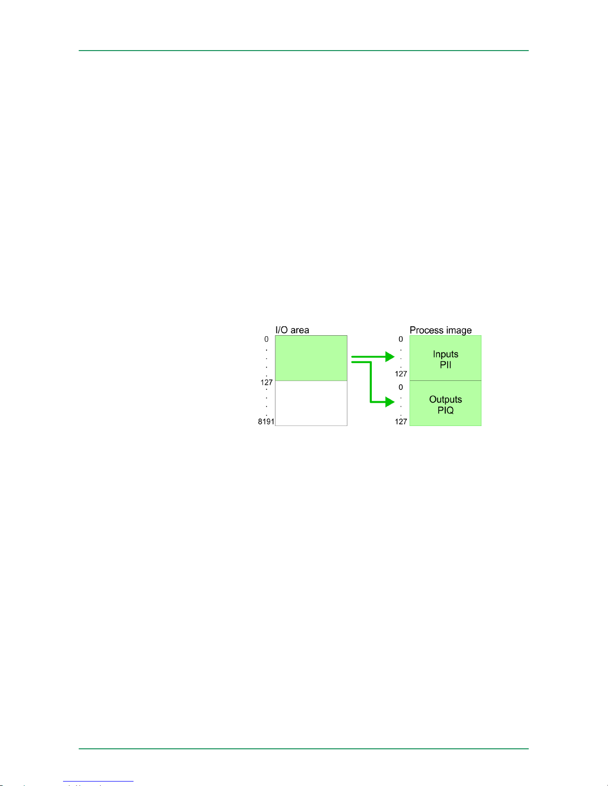
The CPU 313-6CF13 provides an I/O area (address 0 ... 8191) and a
process image of the in- and outputs (each address 0 ... 127). The
process image stores the signal states of the lower address (0 ... 127)
additionally in a separate memory area.
The process image this divided into two parts:
n process image to the inputs (PII)
n process image to the outputs (PIQ)
The process image is updated automatically when a cycle has been
completed.
At deployment of the CPU 313-6CF13 you may control up to 31
modules at the bus. Here the maximum of 8 modules per row may be
parameterized.
For the project engineering of more than 8 modules line interface connections are to be used. For this you set in the hardware configurator
the module IM 360 from the hardware catalog to slot 3 of your 1. profile rail. Now you may extend your system with up to 3 profile rails by
starting each with an IM 361 from Siemens at slot 3.
You may access the modules with read res. write accesses to the
peripheral bytes or the process image. To define addresses a hardware configuration may be used. For this, click on the properties of
the according module and set the wanted address.
If you do not like to use a hardware configuration, an automatic
addressing comes into force. At the automatic address allocation
DIOs occupy depending on the slot location always 4byte and AIOs,
FMs, CPs always 16byte at the bus. Depending on the slot location
the start address from where on the according module is stored in the
address range is calculated with the following formulas:
Max. number of pluggable modules
Define addresses by
hardware configuration
Automatic addressing
VIPA System 300SDeployment CPU 313-6CF13
Addressing > Addressing Backplane bus I/O devices
HB140 | CPU-SC | 313-6CF13 | GB | 15-50 48
Page 49
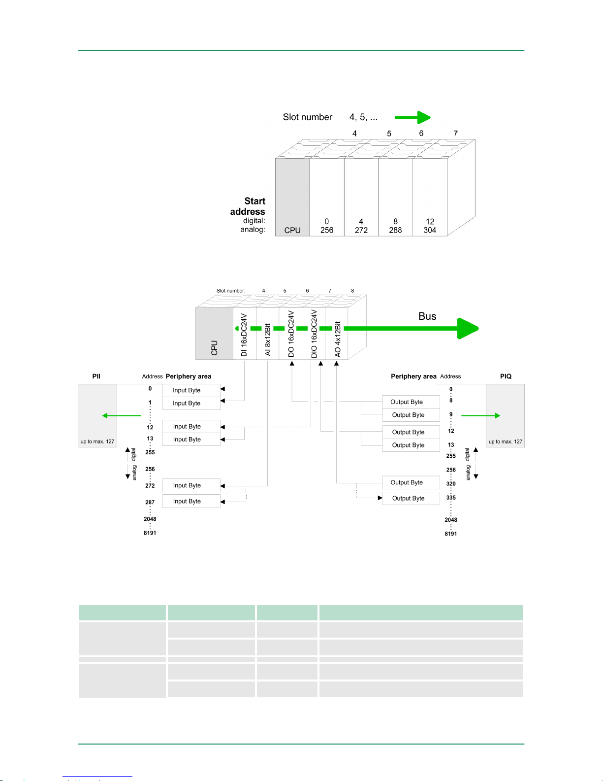
n DIOs: Start address = 4×(slot -4)
n AIOs, FMs, CPs: Start address = 16×(slot -4)+256
The following sample shows the functionality of the automatic
address allocation:
5.4 Address assignment
Sub module Default address Access Assignment
DI16/DO16 124 Byte Digital Input I+0.0 ... I+0.7
125 Byte Digital Input I+1.0 ... I+1.7
Counter 768 DInt Channel 0: Count value / Frequency value
772 DInt Channel 1: Count value / Frequency value
Example for automatic
address allocation
Input range
VIPA System 300S Deployment CPU 313-6CF13
Address assignment
HB140 | CPU-SC | 313-6CF13 | GB | 15-50 49
Page 50
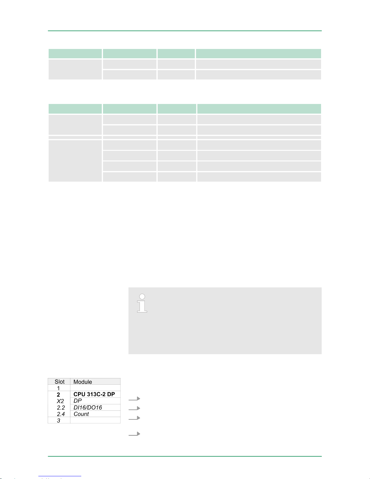
Sub module Default address Access Assignment
776 DInt Channel 2: Count value / Frequency value
780 DInt reserved
Sub module Default address Access Assignment
DI16/DO16 124 Byte Digital Output Q+0.0 ... Q+0.7
125 Byte Digital Output Q+1.0 ... Q+1.7
Counter 768 DWort reserved
772 DWort reserved
776 DWort reserved
780 DWort reserved
5.5 Hardware configuration - CPU
The configuration of the CPU takes place at the Siemens ‘hardware
configurator’ . The hardware configurator is part of the Siemens
SIMATIC Manager. It serves for project engineering. The modules,
which may be configured here are listed in the hardware catalog. If
necessary you have to update the hardware catalog with ‘Options
è Update Catalog’.
For project engineering a thorough knowledge of the Siemens
SIMATIC Manager and the Siemens hardware configurator is
required.
Please consider that this SPEED7-CPU has 4 ACCUs.
After an arithmetic operation (+I, -I, *I, /I, +D, -D, *D, /D,
MOD, +R, -R, *R, /R) the content of ACCU 3 and ACCU 4
is loaded into ACCU 3 and 2. This may cause conflicts in
applications that presume an unmodified ACCU 2.
For more information may be found in the manual "VIPA
Operation list SPEED7" at "Differences between SPEED7
and 300V programming".
To be compatible with the Siemens SIMATIC Manager the following
steps should be executed:
1. Start the Siemens hardware configurator with a new project.
2. Insert a profile rail from the hardware catalog.
3. Place at ‘Slot’ number 2 the Siemens CPU 313C-2DP (6ES7
313-6CF03-0AB0 V2.6).
4. The integrated PROFIBUS DP master (socket X3) is to be configured and connected via the sub module X2 (DP).
Output range
Precondition
Proceeding
VIPA System 300SDeployment CPU 313-6CF13
Hardware configuration - CPU
HB140 | CPU-SC | 313-6CF13 | GB | 15-50 50
Page 51
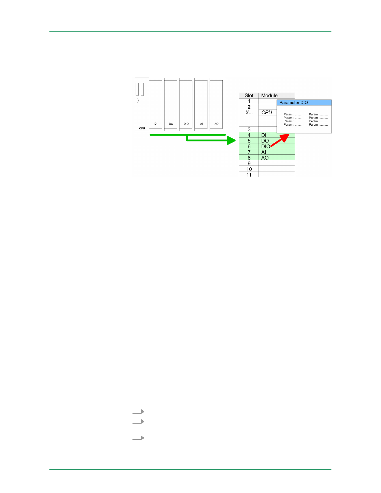
5.6 Hardware configuration - I/O modules
After the hardware configuration place the System 300 modules in the
plugged sequence starting with slot 4.
For parametrization double-click during the project engineering at the
slot overview on the module you want to parameterize. In the
appearing dialog window you may set the wanted parameters. By
using the SFCs 55, 56 and 57 you may alter and transfer parameters
for wanted modules during runtime. For this you have to store the
module specific parameters in so called "record sets". More detailed
information about the structure of the record sets is to find in the
according module description.
Maximally 31 modules may be addressed by the CPU 313-6CF13,
but per row maximally 8 modules are supported. For project engineering the IM 360 of the hardware catalog are to be used as a bus
extension during project engineering. Here 3 further extension racks
can be connected via the IM 361. Bus extensions are always placed
at slot 3.
5.7
Hardware configuration - Ethernet PG/OP channel
The CPU 313-6CF13 has an integrated Ethernet PG/OP channel.
This channel allows you to program and remote control your CPU.
The PG/OP channel also gives you access to the internal web page
that contains information about firmware version, connected I/O
devices, current cycle times etc. With the first start-up respectively
after an overall reset the Ethernet PG/OP channel does not have any
IP address. For online access to the CPU via Ethernet PG/OP
channel valid IP address parameters have to be assigned to this by
means of the Siemens SIMATIC Manager. This is called "initialization".
1. Install your System 300S with your CPU.
2. Wire the system by connecting cables for voltage supply and
signals.
3. Connect the Ethernet jack of the Ethernet PG/OP channel to
Ethernet
Hardware configuration
of the modules
Parametrization
Bus extension with IM
360 and IM 361
Overview
Assembly and commissioning
VIPA System 300S Deployment CPU 313-6CF13
Hardware configuration - Ethernet PG/OP channel
HB140 | CPU-SC | 313-6CF13 | GB | 15-50 51
Page 52
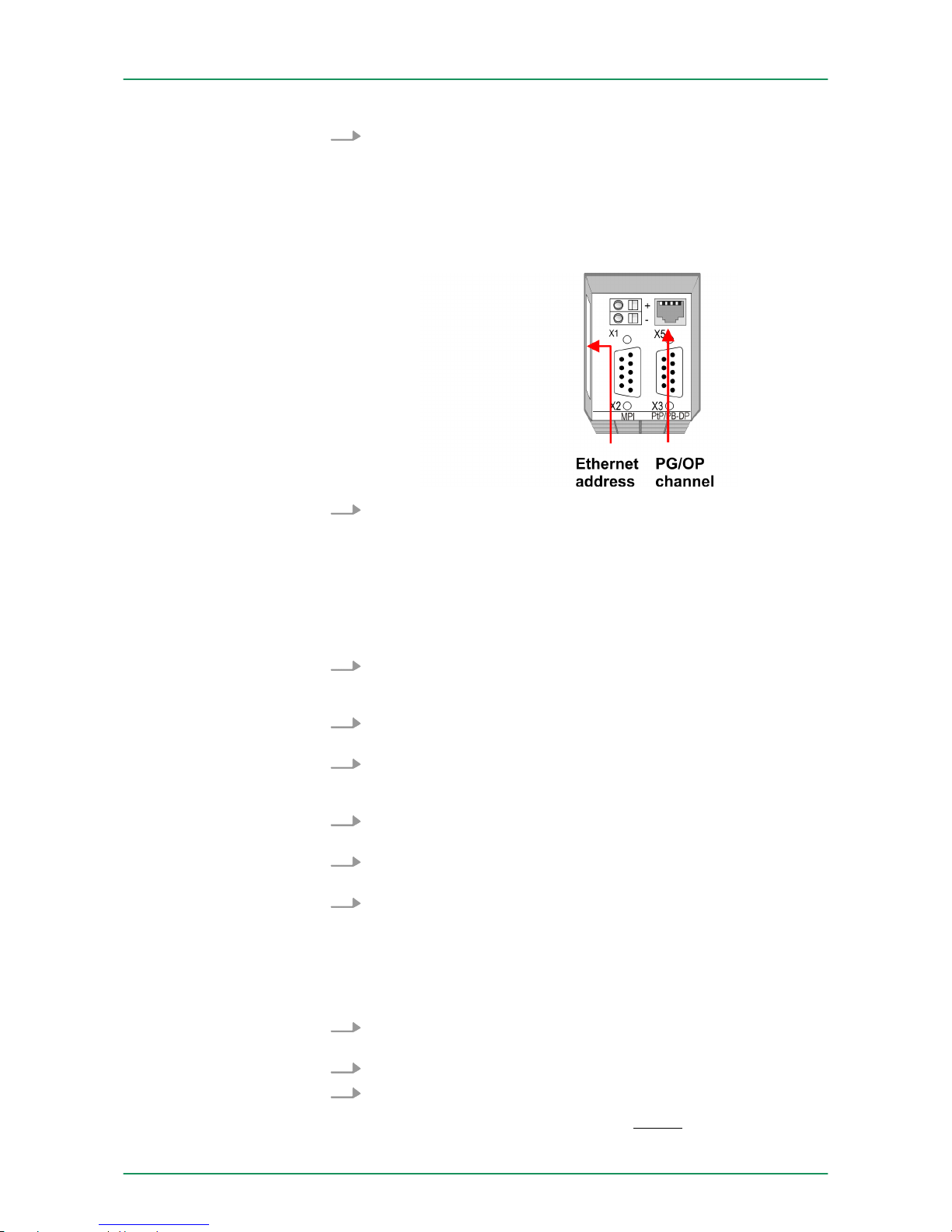
4. Switch on the power supply.
ð
After a short boot time the CP is ready for communication.
He possibly has no IP address data and requires an initialization.
The initialization via PLC functions takes place with the following proceeding:
Determine the current Ethernet (MAC) address of your Ethernet
PG/OP channel. This always may be found as 1. address under
the front flap of the CPU on a sticker on the left side.
You get valid IP address parameters from your system administrator.
The assignment of the IP address data happens online in the Siemens SIMATIC Manager starting with version V 5.3 & SP3 with the
following proceeding:
1. Start the Siemens SIMATIC Manager and set via ‘Options
è Set PG/PC interface
’ the access path to ‘TCP/IP -> Network
card ....’ .
2.
Open with ‘PLC è Edit Ethernet Node n
’ the dialog window with
the same name.
3. To get the stations and their MAC address, use the [Browse]
button or type in the MAC Address. The Mac address may be
found at the 1. label beneath the front flap of the CPU.
4. Choose if necessary the known MAC address of the list of found
stations.
5. Either type in the IP configuration like IP address, subnet mask
and gateway.
6. Confirm with [Assign IP configuration].
ð
Direct after the assignment the Ethernet PG/OP channel
may be reached online by these address data. The value
remains as long as it is reassigned, it is overwritten by a
hardware configuration or an factory reset is executed.
1. Open the Siemens hardware configurator und configure the Siemens CPU 313C-2DP (6ES7 313-6CF03-0AB0 V2.6).
2. Configure the modules at the standard bus.
3. For the Ethernet PG/OP channel you have to configure a Sie-
mens CP 343-1 (SIMATIC 300 \ CP 300 \ Industrial Ethernet
\CP 343-1 \ 6GK7 343-1EX11 0XE0) always below the really
plugged modules.
"Initialization" via PLC
functions
Assign IP address
parameters
Take IP address parameters in project
VIPA System 300SDeployment CPU 313-6CF13
Hardware configuration - Ethernet PG/OP channel
HB140 | CPU-SC | 313-6CF13 | GB | 15-50 52
Page 53
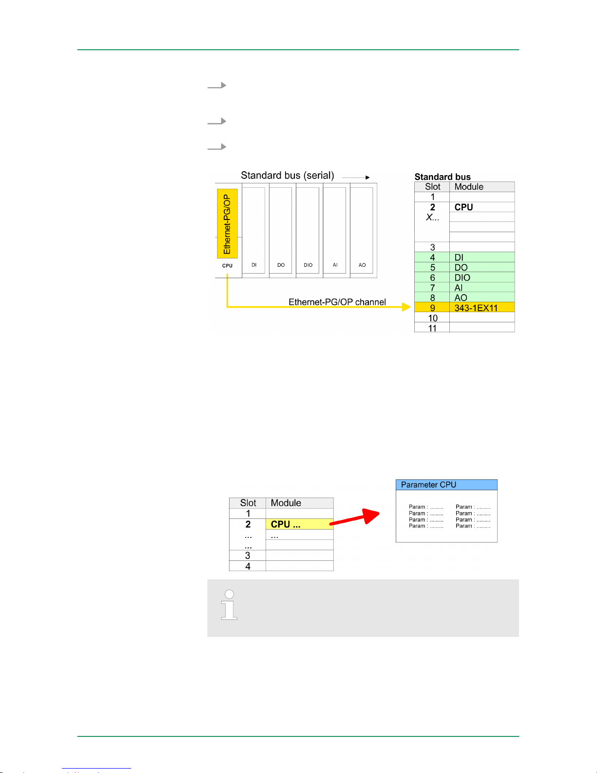
4. Open the property window via double-click on the CP
343-1EX11 and enter for the CP at ‘Properties’
the IP address
data, which you have assigned before.
5. Assign the CP to a ‘Subnet’ . Without assignment the IP address
data are not used!
6. Transfer your project.
5.8 CPU parametrization
5.8.1 Parametrization via Siemens CPU
Since the CPU is to be configured as Siemens CPU 313C-2DP (6ES7
313-6CF03-0AB0 V2.6) in the Siemens hardware configurator, the
parameters of the CPU 313-6CF13 may be set with "Object properties" of the CPU 313C-2DP during hardware configuration. Via a
double-click on the CPU 313C-2DP the parameter window of the
CPU may be accessed. Using the registers you get access to every
parameter of the CPU.
Description of the parameters of the sub modules ‘DI16/
DO16’
and ‘Counter’ :
Ä
Chapter 6 ‘Deployment I/O periphery’ on page 96
5.8.2 CPU parameters
The CPU does not evaluate each parameter, which may be set at the
hardware configuration. The following parameters are supported by
the CPU at this time:
Parameterization via
Siemens CPU 313C-2DP
Supported parameters
VIPA System 300S Deployment CPU 313-6CF13
CPU parametrization > CPU parameters
HB140 | CPU-SC | 313-6CF13 | GB | 15-50 53
Page 54

n Short description:
The short description of the Siemens CPU 313-6CF03 is CPU
313C-2DP.
n Order No. / Firmware:
Order number and firmware are identical to the details in the
"hardware catalog" window.
n Name:
The Name field provides the short description of the CPU. If you
change the name the new name appears in the Siemens
SIMATIC Manager.
n Interface:
Here is the address of the MPI interface.
n Properties:
By means of this button you can change the properties of the MPI
interface.
n Comment:
In this field information about the module may be entered.
n Startup when expected/actual configuration differs:
If the checkbox for ‘Startup when expected/actual configuration
differ’ is deselected and at least one module is not located at its
configured slot or if another type of module is inserted there
instead, then the CPU does not switch to RUN mode and remains
in STOP mode. If the checkbox for ‘Startup when expected/actual
configuration differ’ is selected, then the CPU starts even if there
are modules not located in their configured slots of if another type
of module is inserted there instead, such as during an initial
system start-up.
n Monitoring time for ready message by modules [100ms]:
This operation specifies the maximum time for the ready message
of every configured module after PowerON. Here connected
PROFIBUS DP slaves are also considered until they are parameterized. If the modules do not send a ready message to the CPU
by the time the monitoring time has expired, the actual configuration becomes unequal to the preset configuration.
n Transfer of parameters to modules [100ms]:
The maximum time for the transfer of parameters to parameterizable modules. If not every module has been assigned parameters
by the time this monitoring time has expired; the actual configuration becomes unequal to the preset configuration.
n Update OB1 process image cyclically:
This parameter is not relevant.
n Scan cycle monitoring time:
Here the scan cycle monitoring time in milliseconds may be set. If
the scan cycle time exceeds the scan cycle monitoring time, the
CPU enters the STOP mode.
Possible reasons for exceeding the time are:
–
Communication processes
– a series of interrupt events
– an error in the CPU program
n Minimum scan cycle time:
This parameter is not relevant.
n Scan cycle load from Communication:
This parameter is not relevant.
General
Startup
Cycle/Clock memory
VIPA System 300SDeployment CPU 313-6CF13
CPU parametrization > CPU parameters
HB140 | CPU-SC | 313-6CF13 | GB | 15-50 54
Page 55

n Size of the process image input/output area:
Here the size of the process image max. 2048 for the input/output
periphery may be fixed.
n OB85 call up at I/O access error:
The preset reaction of the CPU may be changed to an I/O access
error that occurs during the update of the process image by the
system. The VIPA CPU is preset such that OB 85 is not called if
an I/O access error occurs and no entry is made in the diagnostic
buffer either.
n Clock memory: Activate the check box if you want to use clock
memory and enter the number of the memory byte.
The selected memory byte cannot be used for temporary
data storage.
n Number of Memory bytes from MB0:
Enter the number of retentive memory bytes from memory byte 0
onwards.
n Number of S7 Timers from T0:
Enter the number of retentive S7 timers from T0 onwards. Each
S7 timer occupies 2bytes.
n Number of S7 Counters from C0:
Enter the number of retentive S7 counter from C0 onwards.
n Areas:
This parameter is not supported.
n Priority:
Here the priorities are displayed, according to which the hardware
interrupt OBs are processed (hardware interrupt, time-delay interrupt, async. error interrupts).
n Priority:
The priority may not be modified.
n Active:
Activate the check box of the time-of-day interrupt OBs if these
are to be automatically started on complete restart.
n Execution:
Select how often the interrupts are to be triggered. Intervals
ranging from every minute to yearly are available. The intervals
apply to the settings made for start date
and time.
n Start date/time:
Enter date and time of the first execution of the time-of-day interrupt.
n Process image partition:
This parameter is not supported.
Retentive Memory
Interrupts
Time-of-day interrupts
VIPA System 300S Deployment CPU 313-6CF13
CPU parametrization > CPU parameters
HB140 | CPU-SC | 313-6CF13 | GB | 15-50 55
Page 56

n Priority:
Here the priorities may be specified according to which the corresponding cyclic interrupt is processed. With priority "0" the corresponding interrupt is deactivated.
n Execution:
Enter the time intervals in ms, in which the watchdog interrupt
OBs should be processed. The start time for the clock is when the
operating mode switch is moved from STOP to RUN.
n Phase offset:
Enter the delay time in ms for current execution for the watch dog
interrupt. This should be performed if several watchdog interrupts
are enabled. Phase offset allows to distribute processing time for
watchdog interrupts across the cycle.
n Process image partition:
This parameter is not supported.
n Level of protection:
Here 1 of 3 protection levels may be set to protect the CPU from
unauthorized access.
– Protection level 1 (default setting):
No password adjustable, no restrictions
– Protection level 2 with password:
Authorized users: read and write access
Unauthorized user: read access only
– Protection level 3:
Authorized users: read and write access
Unauthorized user: no read and write access
5.9 Setting VIPA specific CPU parameters
5.9.1
Proceeding
Except of the VIPA specific CPU parameters the CPU parametrization takes place in the parameter dialog of the CPU 313C-2DP from
Siemens. With installing of the SPEEDBUS.GSD the VIPA specific
parameters may be set during hardware configuration. Here the following parameters may be accessed:
n Function RS485 X3 (PtP, Synchronization between DP master
and CPU)
n Token Watch
Since the VIPA specific CPU parameters may be set, the installation
of the SPEEDBUS.GSD from VIPA in the hardware catalog is necessary. The CPU may be configured in a PROFIBUS master system
and the appropriate parameters may be set after installation.
Cyclic interrupts
Protection
Overview
Requirements
VIPA System 300SDeployment CPU 313-6CF13
Setting VIPA specific CPU parameters > Proceeding
HB140 | CPU-SC | 313-6CF13 | GB | 15-50 56
Page 57

The GSD (Geräte-Stamm-Datei) is online available in the following
language versions. Further language versions are available on
inquires:
Name Language
SPEEDBUS.GSD german (default)
SPEEDBUS.GSG german
SPEEDBUS.GSE english
The GSD files may be found at www.vipa.com at the "Service" part.
The integration of the SPEEDBUS.GSD takes place with the following
proceeding:
1. Browse to www.vipa.com
2.
Click to ‘Service è Download è GSD- and EDS-Files
è Profibus’
3. Download the file Cx000023_Vxxx.
4. Extract the file to your work directory. The SPEEDBUS.GSD is
stored in the directory VIPA_System_300S.
5. Start the hardware configurator from Siemens.
6. Close every project.
7.
Select ‘Options è Install new GSD-file
’.
8. Navigate to the directory VIPA_System_300S and select
SPEEDBUS.GSD an.
ð
The SPEED7 CPUs and modules of the System 300S from
VIPA may now be found in the hardware catalog at
PROFIBUS-DP / Additional field devices / I/O /
VIPA_SPEEDBUS.
The embedding of the CPU 313-6CF13 happens by means of a virtual PROFIBUS master system with the following approach:
Installation of the
SPEEDBUS.GSD
Hardware configuration
VIPA System 300S Deployment CPU 313-6CF13
Setting VIPA specific CPU parameters > Proceeding
HB140 | CPU-SC | 313-6CF13 | GB | 15-50 57
Page 58
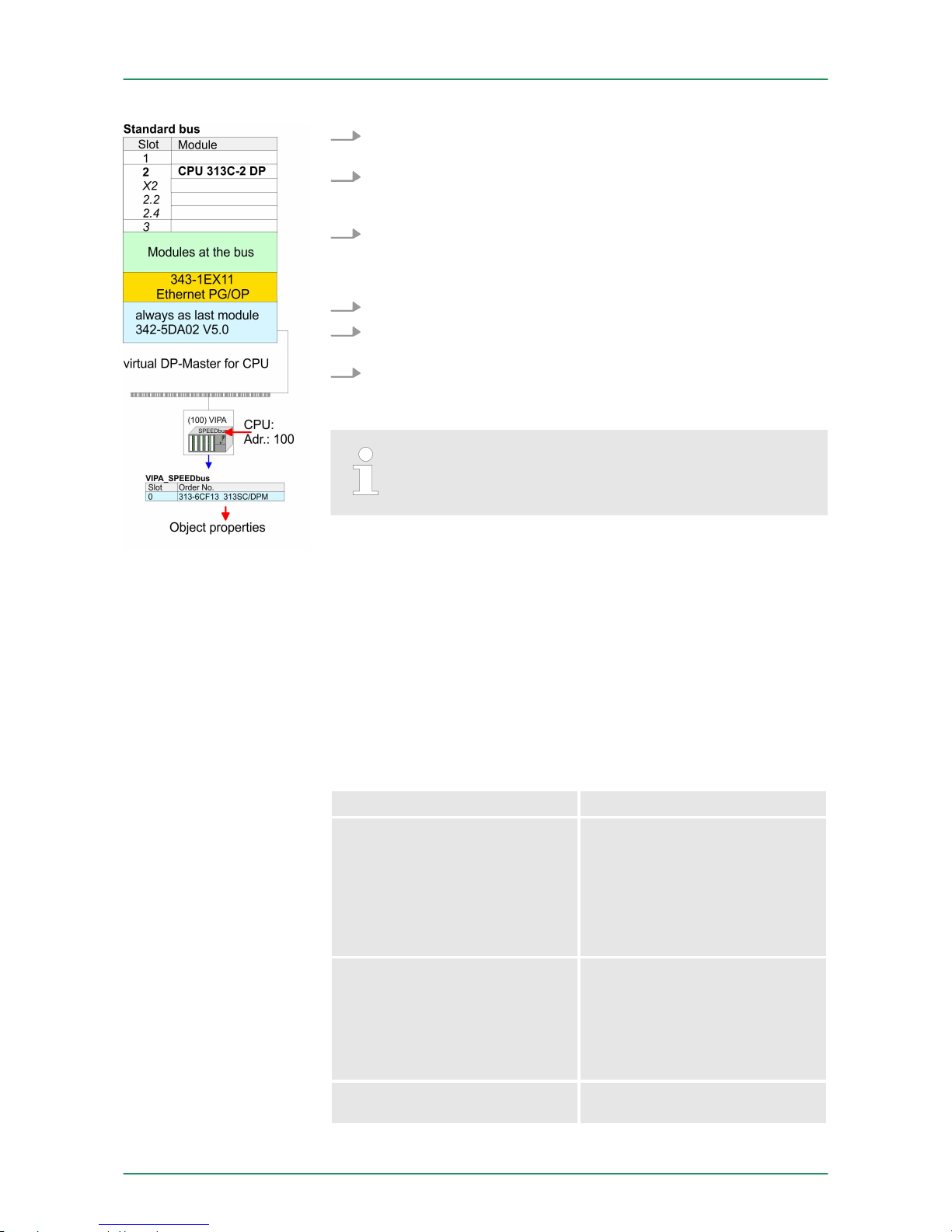
1.
Perform a hardware configuration for the CPU.
Ä
Chapter 5.5
‘Hardware configuration - CPU’ on page 50
2. Configure always as last module a Siemens DP master CP
342-5 (342-5DA02 V5.0). Connect and parameterize it at operation mode "DP-Master".
3. Connect the slave system "VIPA_SPEEDbus". After installing
the SPEEDBUS.GSD this may be found in the hardware catalog
at Profibus-DP / Additional field devices / I/O / VIPA /
VIPA_SPEEDBUS.
4. For the slave system set the PROFIBUS address 100.
5. Configure at slot 0 the VIPA CPU 313-6CF13 of the hardware
catalog from VIPA_SPEEDbus.
6. By double clicking the placed CPU 313-6CF13 the properties
dialog of the CPU may be opened.
The hardware configuration, which is shown here, is only
required, if you want to customize the VIPA specific
parameters.
5.9.2 VIPA specific parameters
The following parameters may be accessed by means of the properties dialog of the VIPA CPU.
5.9.2.1
Function RS485 X3
Using this parameter the RS485 interface may be switched to PtP
communication (point to point) respectively the synchronization
between DP master system and CPU may be set:
Deactivated Deactivates the RS485 interface.
PtP With this operating mode the
PROFIBUS DP master is deactivated and the RS485 interface
acts as an interface for serial
point-to-point communication.
Here data may be exchanged
between two stations by means
of protocols.
PROFIBUS DP async PROFIBUS DP master operation
asynchronous to CPU cycle The
RS485 interface is preset at
default to PROFIBUS DP async.
Here CPU cycle and cycles of
every VIPA PROFIBUS DP
master run independently.
PROFIBUS DP syncIn The CPU is waiting for DP
master input data.
VIPA System 300SDeployment CPU 313-6CF13
Setting VIPA specific CPU parameters > VIPA specific parameters
HB140 | CPU-SC | 313-6CF13 | GB | 15-50 58
Page 59
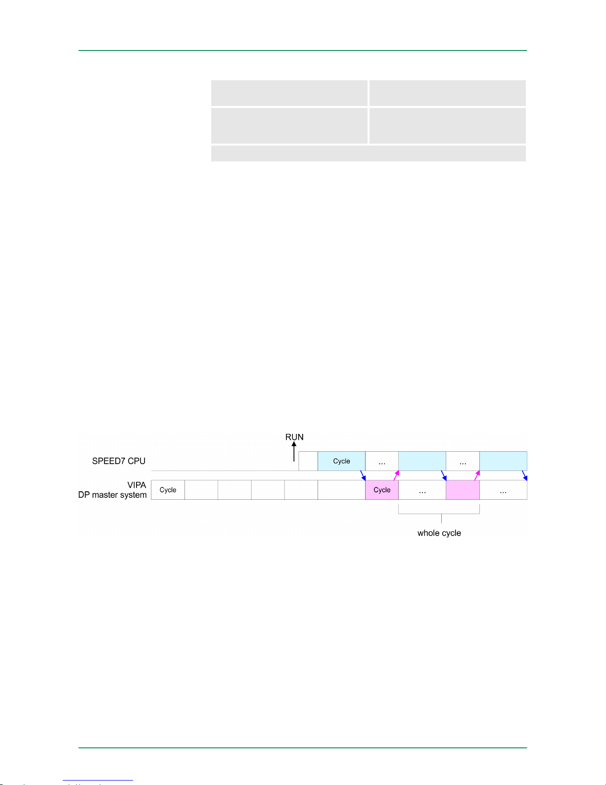
PROFIBUS DP syncOut The DP master system is waiting
for CPU output data.
PROFIBUS DP syncInOut CPU and DP master system are
waiting on each other and form
thereby a cycle.
Default: PROFIBUS DP async
5.9.2.1.1 Synchronization between master system and CPU
Normally the cycles of CPU and DP master run independently. The
cycle time of the CPU is the time needed for one OB1 cycle and for
reading respectively writing the inputs respectively outputs. The cycle
time of a DP master depends among others on the number of connected slaves and the baud rate, thus every plugged DP master has
its own cycle time. Due to the asynchronism of CPU and DP master
the whole system gets relatively high response times. The synchronization behavior between every VIPA PROFIBUS DP master and the
CPU may be configured by means of a hardware configuration as
shown above. The different modes for the synchronization are in the
following described.
In PROFIBUS DP SyncInOut mode CPU and DP master system are
waiting on each other and form thereby a cycle. Here the whole cycle
is the sum of the longest DP master cycle and CPU cycle. By this
synchronization mode you receive global consistent in-/ output data,
since within the total cycle the same input and output data are handled successively by CPU and DP master system. If necessary the
time of the Watchdog of the bus parameters should be increased at
this mode.
In this operating mode the cycle time of the VIPA DP master system
depends on the CPU cycle time. After CPU start-up the DP master
gets synchronized. As soon as their cycle is passed they wait for the
next synchronization impulse with output data of the CPU. So the
response time of your system can be improved because output data
were directly transmitted to the DP master system. If necessary the
time of the Watchdog of the bus parameters should be increased at
this mode.
Overview
PROFIBUS DP
SyncInOut
PROFIBUS DP SyncOut
VIPA System 300S Deployment CPU 313-6CF13
Setting VIPA specific CPU parameters > VIPA specific parameters
HB140 | CPU-SC | 313-6CF13 | GB | 15-50 59
Page 60
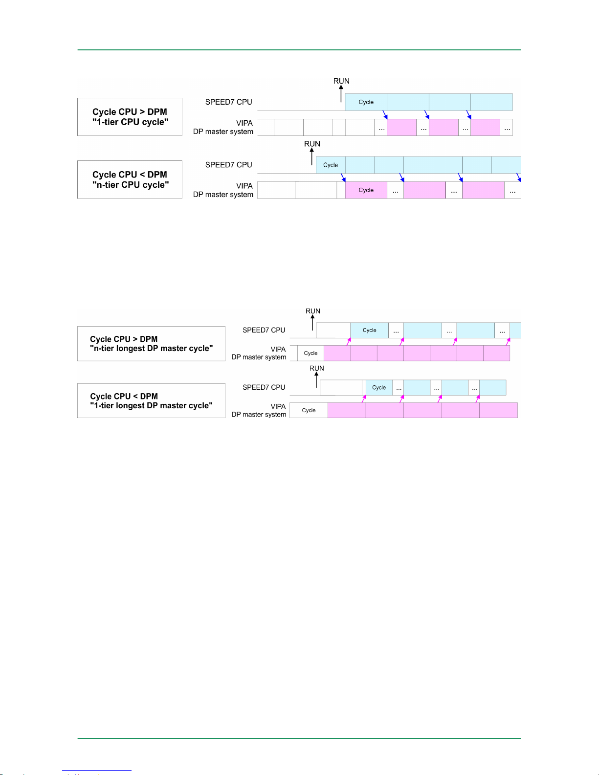
In the operating mode PROFIBUS DP SyncIn the CPU cycle is
synchronized to the cycle of the VIPA PROFIBUS DP master system.
Here the CPU cycle depends on the VIPA DP master with the longest
cycle time. If the CPU gets into RUN it is synchronized with each
PROFIBUS DP master. As soon as the CPU cycle is passed, it waits
for the next synchronization impulse with input data of the DP master
system. If necessary the Scan Cycle Monitoring Time of the CPU
should be increased.
5.9.2.2 Token Watch
By presetting the PROFIBUS bus parameters within the hardware
configuration a token time for the PROFIBUS results. The token time
defines the duration until the token reaches the DP master again. Per
default this time is supervised. Due to this monitoring disturbances on
the bus can affect a reboot of the DP master. Here with the parameter
Token Watch the monitoring of the token time can be switched off
respectively on.
Default: On
5.10
Project transfer
There are the following possibilities for project transfer into the CPU:
n Transfer via MPI/PROFIBUS
n Transfer via Ethernet
n Transfer via MMC
5.10.1 Transfer via MPI/PROFIBUS
For transfer via MPI/PROFIBUS there is the following interface:
PROFIBUS-DP SyncIn
Overview
General
VIPA System 300SDeployment CPU 313-6CF13
Project transfer > Transfer via MPI/PROFIBUS
HB140 | CPU-SC | 313-6CF13 | GB | 15-50 60
Page 61
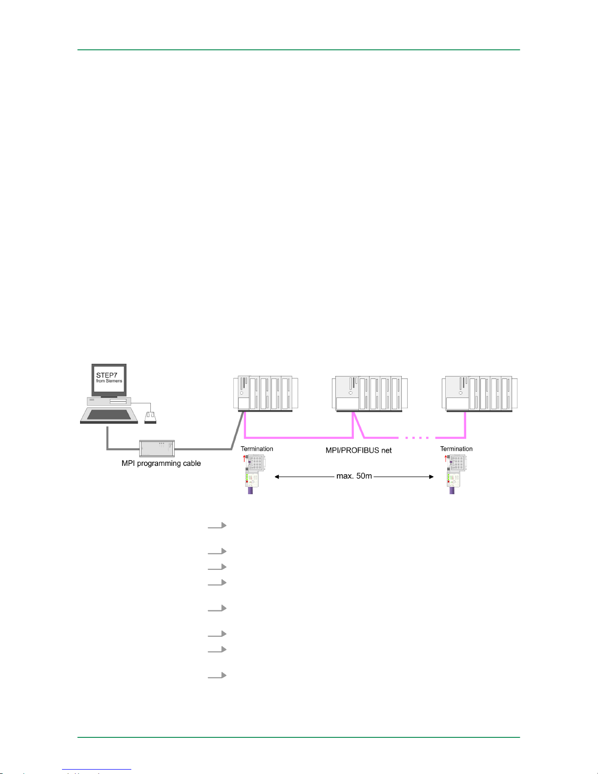
n X2: MPI interface
n X3: PROFIBUS interface
The structure of a MPI net is electrically identical with the structure of
a PROFIBUS net. This means the same rules are valid and you use
the same components for the build-up. The single participants are
connected with each other via bus interface plugs and PROFIBUS
cables. Please consider with the CPU 313-6CF13 that the total extension of the MPI net does not exceed 50m. Per default the MPI net
runs with 187.5kbaud. VIPA CPUs are delivered with MPI address 2.
The MPI programming cables are available at VIPA in different variants. The cables provide a RS232 res. USB plug for the PC and a
bus enabled RS485 plug for the CPU. Due to the RS485 connection
you may plug the MPI programming cables directly to an already
plugged plug on the RS485 jack. Every bus participant identifies itself
at the bus with an unique address, in the course of the address 0 is
reserved for programming devices.
A cable has to be terminated with its surge impedance. For this you
switch on the terminating resistor at the first and the last participant of
a network or a segment. Please make sure that the participants with
the activated terminating resistors are always power supplied. Otherwise it may cause interferences on the bus.
1. Connect your PC to the MPI jack of your CPU via a MPI programming cable.
2. Load your project in the SIMATIC Manager from Siemens.
3.
Choose in the menu ‘Options è Set PG/PC interface’.
4. Select in the according list the "PC Adapter (MPI)"; if appropriate
you have to add it first, then click on [Properties].
5. Set in the register MPI the transfer parameters of your MPI net
and type a valid address.
6. Switch to the register Local connection.
7. Set the COM port of the PCs and the transfer rate 38400Baud
for the MPI programming cable from VIPA.
8.
Via ‘PLC è Load to module
’ via MPI to the CPU and save it on
a MMC via ‘PLC è Copy RAM to ROM’ if one is plugged.
Net structure
MPI programming cable
Terminating resistor
Approach transfer via
MPI interface
VIPA System 300S Deployment CPU 313-6CF13
Project transfer > Transfer via MPI/PROFIBUS
HB140 | CPU-SC | 313-6CF13 | GB | 15-50 61
Page 62

1. Connect your PC to the PB-DP jack X3 of your CPU via a MPI
programming cable.
2. Load your project in the Siemens SIMATIC Manager.
3.
Choose in the menu ‘Options è Set PG/PC interface’.
4. Select in the according list the "PC Adapter (PROFIBUS)"; if
appropriate you have to add it first, then click at [Properties].
5. Set in the register PROFIBUS the transfer parameters of your
PROFIBUS net and enter a valid PROFIBUS address. The
PROFIBUS address
must be assigned to the DP master by a
project before.
6. Switch to the register Local connection.
7. Set the COM port of the PCs and the transfer rate 38400baud
for the MPI programming cable from VIPA.
8.
Transfer your project via ‘PLC è Load to module’
via
PROFIBUS to the CPU and save it with ‘PLC
è Copy RAM to ROM’ on a memory card if one is plugged.
Transfer via PROFIBUS is available by DP master, if projected as master and assigned with a PROFIBUS address
before.
Within selecting the slave mode you have additionally to
select the option "Test, commissioning, routing".
5.10.2 Transfer via Ethernet
For transfer via Ethernet the CPU has the following interface:
n X5: Ethernet PG/OP channel
So that you may access the Ethernet PG/OP channel you have to
assign IP address parameters by means of the "initialization".
Ä
Chapter 5.7 ‘Hardware configuration - Ethernet PG/OP channel’
on page 51
1. For the transfer, connect, if not already done, the appropriate
Ethernet port to your Ethernet.
2. Open your project with the Siemens SIMATIC Manager.
3.
Set via ‘Options è Set PG/PC Interface
’ the access path to
"TCP/IP ® Network card .... ".
4.
Click to ‘PLC è Download
’ Download ® the dialog "Select
target module" is opened. Select your target module and enter
the IP address parameters of the Ethernet PG/OP channel for
connection. Provided that no new hardware configuration is
transferred to the CPU, the entered Ethernet connection is permanently stored in the project as transfer channel.
5. With [OK] the transfer is started.
Proceeding Transfer via
PROFIBUS interface
Initialization
Transfer
VIPA System 300SDeployment CPU 313-6CF13
Project transfer > Transfer via Ethernet
HB140 | CPU-SC | 313-6CF13 | GB | 15-50 62
Page 63

System dependent you get a message that the projected
system differs from target system. This message may be
accepted by [OK].
®
Your project is transferred and may be executed in the
CPU after transfer.
5.10.3 Transfer via MMC
The MMC (Memory Card) serves as external transfer and storage
medium. There may be stored several projects and sub-directories on
a MMC storage module. Please regard that your current project is
stored in the root directory and has one of the following file names:
n S7PROG.WLD
n AUTOLOAD.WLD
With ‘File è Memory Card File è New
’ in the Siemens SIMATIC
Manager a new wld file may be created. After the creation copy the
blocks from the project blocks folder and the System data into the wld
file.
The transfer of the application program from the MMC into the CPU
takes place depending on the file name after an overall reset or PowerON.
n S7PROG.WLDis read from the MMC after overall reset.
n AUTOLOAD.WLD is read after PowerON from the MMC.
The blinking of the MC LED of the CPU marks the active transfer.
Please regard that your user memory serves for enough space, otherwise your user program is not completely loaded and the SF LED
gets on.
When the MMC has been installed, the write command stores the
content of the battery buffered RAM as S7PROG.WLD on the MMC.
The write command is controlled by means of the block area of the
Siemens SIMATIC Manager ‘PLC è Copy RAM to ROM’. During the
write process the MC LED of the CPU is blinking. When the LED
expires the write process is finished.
If this project is to be loaded automatically from the MMC with PowerON, you have to rename this on the MMC to AUTOLOAD.WLD.
After a MMC access, an ID is written into the diagnostic buffer of the
CPU. To monitor the diagnosis entries, you select ‘PLC
è Module Information
’ in the Siemens SIMATIC Manager. Via the
register "Diagnostic Buffer" you reach the diagnosis window.
Information about the event IDs
Ä
Chapter 5.20 ‘VIPA specific diag-
nostic entries’ on page 79.
Transfer MMC ® CPU
Transfer CPU ® MMC
Transfer control
VIPA System 300S Deployment CPU 313-6CF13
Project transfer > Transfer via MMC
HB140 | CPU-SC | 313-6CF13 | GB | 15-50 63
Page 64
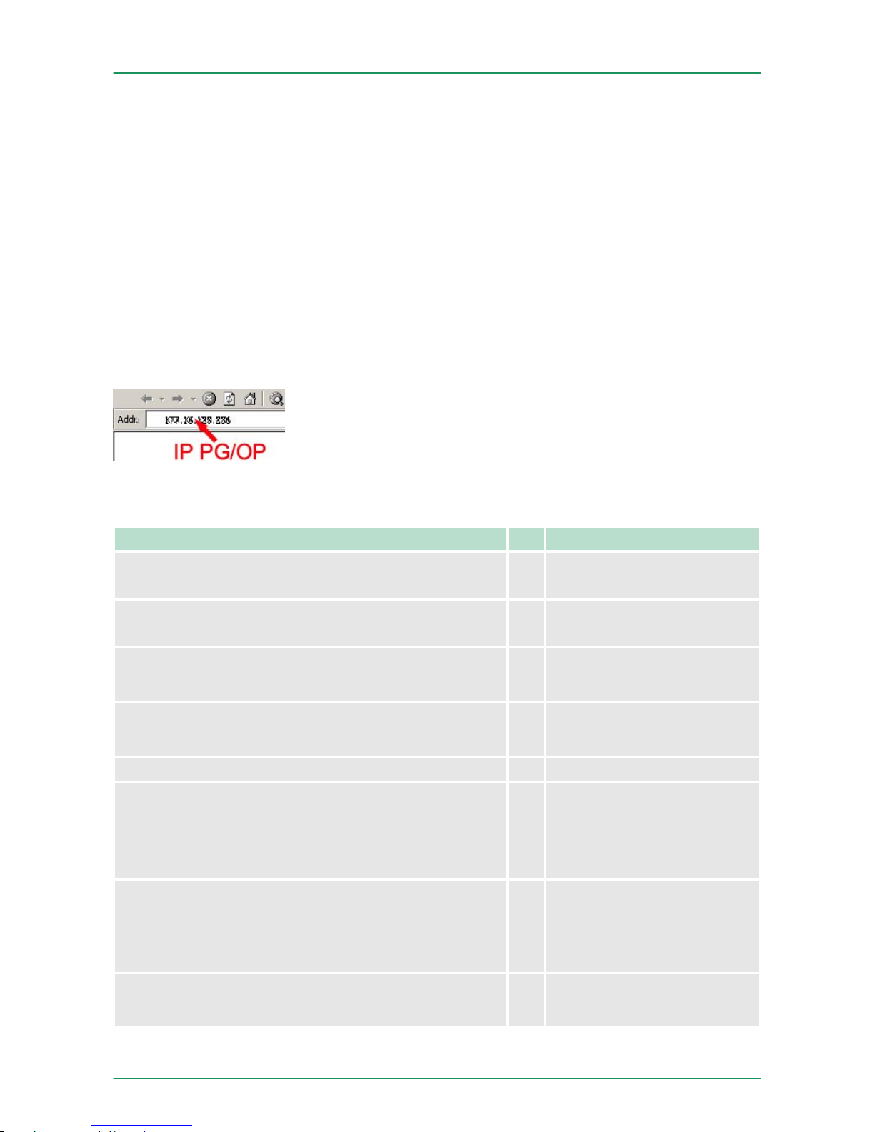
5.11 Access to the internal Web page
The Ethernet PG/OP channel provides a web page that you may
access via an Internet browser by its IP address. The web page contains information about firmware versions, current cycle times etc.
The current content of the web page is stored on MMC by means of
the MMC-Cmd WEBPAGE.
Ä
Chapter 5.19 ‘MMC-Cmd - Auto com-
mands’ on page 77
A PG/OP channel connection should be established between PC with
Internet browser and CPU 313-6CF13. This may be tested by Ping to
the IP address of the PG/OP channel.
The access takes place via the IP address of the Ethernet PG/OP
channel. The web page only serves for information output. The monitored values are not alterable.
CPU with Ethernet-PG/OP
Slot 100
VIPA 313-6CF13 V.... Px000137.pkg,
SERIALNUMBER 02119
Order no., firmware vers.,
package, serial no.
SUPPORTDATA :
PRODUCT V3118, HARDWARE ...
Information for support
Memorysizes (Bytes) : LoadMem : 524288, Work-MemCode : 248968, WorkMemData : 248968
Information about memory configuration, load memory, work
memory (code/data)
OnBoardEthernet : MacAddress : 0020D50144C1, IPAddress : 172.20.120.62, SubnetMask : 255.255.255.0,
Gateway : 172.20.120.62
Ethernet PG/OP: Addresses
Cpu state : Run CPU state
FunctionRS485 X2/COM1: MPI
FunctionRS485 X3/COM2: DPM-async
Operating mode RS485
n MPI: MPI operation
n DPM: DP master operation
or
PtP: point to point operation
Cycletime [microseconds] : min=0 cur=770 ave=750
max=878
CPU cycle time:
min = minimal
cur = current
max = maximal
MCC-Trial-Time: 70:23 Remaining time in hh:mm for
deactivation of the expansion
memory if MCC is removed.
Access to the web page
Requirements
Web page
VIPA System 300SDeployment CPU 313-6CF13
Access to the internal Web page
HB140 | CPU-SC | 313-6CF13 | GB | 15-50 64
Page 65

Slot 201 CPU component:
DP master
VIPA 342-1DA70 V3.3.0 Px000064.pkg Name, firmware-version,
package
SUPPORTDATA :
PRODUCT V3300, BB000218 V5300, AB000068 V4170,
ModuleType CB2C0010
Information for support
Cycletime [microseconds] : min=17000 cur=17000
ave=17000 max=17000
CPU cycle time:
min = minimal
cur = current
max = maximal
Slot 202 CPU component: Digital I/Os
VIPA DI16/DO16 V3.2.9,SUPPORTDATA:PRODUCT... Name, firmware version,
module type
SUPPORTDATA: PRODUCT V3290, Module Type ... Information for support
Address Input 124...125 Configured input base
addresses
Address Output 124...125 Configured output base
addresses
Slot 204 CPU component: Counter
VIPA 3 COUNTERS V3.2.9, Name, firmware version,
module type
SUPPORTDATA: PRODUCT V3290, Module Type ... Information for support
Address Input 768...783 Configured input base
addresses
Address Output 768...783 Configured output base
addresses
Standard Bus
Standard Bus Modules at the standard bus
8 Bit Mode Information for support
VIPA System 300S Deployment CPU 313-6CF13
Access to the internal Web page
HB140 | CPU-SC | 313-6CF13 | GB | 15-50 65
Page 66

5.12 Operating modes
5.12.1
Overview
The CPU can be in one of 4 operating modes:
n Operating mode STOP
n Operating mode START-UP
n Operating mode RUN
n Operating mode HALT
Certain conditions in the operating modes START-UP and RUN
require a specific reaction from the system program. In this case the
application interface is often provided by a call to an organization
block that was included specifically for this event.
n The application program is not processed.
n If there has been a processing before, the values of counters,
timers, flags and the process image are retained during the transition to the STOP mode.
n Outputs are inhibited, i.e. all digital outputs are disabled.
n RUN-LED off
n STOP-LED on
n During the transition from STOP to RUN a call is issued to the
start-up organization block OB 100. The processing time for this
OB is not monitored. The START-UP OB may issue calls to other
blocks.
n All digital outputs are disabled during the START-UP, i.e. outputs
are inhibited.
n RUN-LED
blinks as soon as the OB 100 is operated and for at least 3s, even
if the start-up time is shorter or the CPU gets to STOP due to an
error. This indicates the start-up.
n STOP-LED off
When the CPU has completed the START-UP OB, it assumes the
operating mode RUN.
n The application program in OB 1 is processed in a cycle. Under
the control of alarms other program sections can be included in
the cycle.
n All timers and counters being started by the program are active
and the process image is updated with every cycle.
n The BASP-signal (outputs inhibited) is deactivated, i.e. all digital
outputs are enabled.
n RUN-LED on
n STOP-LED off
The CPU offers up to 3 breakpoints to be defined for program diagnosis. Setting and deletion of breakpoints happens in your programming environment. As soon as a breakpoint is reached, you may
process your program step by step.
For the usage of breakpoints, the following preconditions have to be
fulfilled:
Operating mode STOP
Operating mode
START-UP
Operating mode RUN
Operating mode HOLD
Precondition
VIPA System 300SDeployment CPU 313-6CF13
Operating modes > Overview
HB140 | CPU-SC | 313-6CF13 | GB | 15-50 66
Page 67

n Testing in single step mode is possible with STL. If necessary
switch the view via ‘View è STL
’ to STL.
n The block must be opened online and must not be protected.
1.
Activate ‘View è Breakpoint Bar
’.
2. Set the cursor to the command line where you want to insert a
breakpoint.
3.
Set the breakpoint with ‘Debug è Set Breakpoint
’.
ð
The according command line is marked with a circle.
4. To activate the breakpoint click on ‘Debug
è Breakpoints Active’.
ð
The circle is changed to a filled circle.
5. Bring your CPU into RUN.
ð
When the program reaches the breakpoint, your CPU
switches to the state HOLD, the breakpoint is marked with
an arrow and the register contents are monitored.
6. Now you may execute the program code step by step via
‘Debug è Execute Next Statement’ or run the program until the
next breakpoint via ‘Debug è Resume’.
7. Delete (all) breakpoints with the option ‘Debug
è Delete All Breakpoints
’.
n The RUN-LED blinks and the STOP-LED is on.
n The execution of the code is stopped. No level is further executed.
n All times are frozen.
n The real-time clock runs is just running.
n The outputs were disabled (BASP is activated).
n Configured CP connections remain exist.
The usage of breakpoints is always possible. Switching to
the operating mode test operation is not necessary.
With more than 2 breakpoints, a single step execution is
not possible.
Approach for working
with breakpoints
Behavior in operating
state HOLD
VIPA System 300S Deployment CPU 313-6CF13
Operating modes > Overview
HB140 | CPU-SC | 313-6CF13 | GB | 15-50 67
Page 68

5.12.2 Function security
The CPUs include security mechanisms like a Watchdog (100ms)
and a parametrizable cycle time surveillance (parametrizable min.
1ms) that stop res. execute a RESET at the CPU in case of an error
and set it into a defined STOP state. The VIPA CPUs are developed
function secure and have the following system properties:
Event concerns Effect
RUN ® STOP general BASP (Befehls-Ausgabe-Sperre, i.e. com-
mand output lock) is set.
central digital outputs The outputs are disabled.
central analog outputs The outputs are disabled.
n Voltage outputs issue 0V
n Current outputs 0...20mA issue 0mA
n Current outputs 4...20mA issue 4mA
If configured also substitute values may be
issued.
decentral outputs Same behavior as the central digital/analog
outputs.
decentral inputs The inputs are cyclically be read by the
decentralized station and the recent values
are put at disposal.
STOP ® RUN res.
PowerON
general First the PII is deleted, then OB 100 is
called. After the execution of the OB, the
BASP is reset and the cycle starts with:
Delete PIO ® Read PII ® OB 1.
decentral inputs The inputs are once be read by the decen-
tralized station and the recent values are
put at disposal.
RUN general The program execution happens cyclically
and can therefore be foreseen: Read PII ®
OB 1 ® Write PIO.
PII: Process image inputs, PIO: Process image outputs
5.13 Overall reset
During the overall reset the entire user memory is erased. Data
located in the memory card is not affected. You have 2 options to initiate an overall reset:
n initiate the overall reset by means of the operating mode switch
n initiate the overall reset by means of the Siemens SIMATIC Man-
ager
You should always issue an overall reset to your CPU
before loading an application program into your CPU to
ensure that all blocks have been cleared from the CPU.
Overview
VIPA System 300SDeployment CPU 313-6CF13
Overall reset
HB140 | CPU-SC | 313-6CF13 | GB | 15-50 68
Page 69
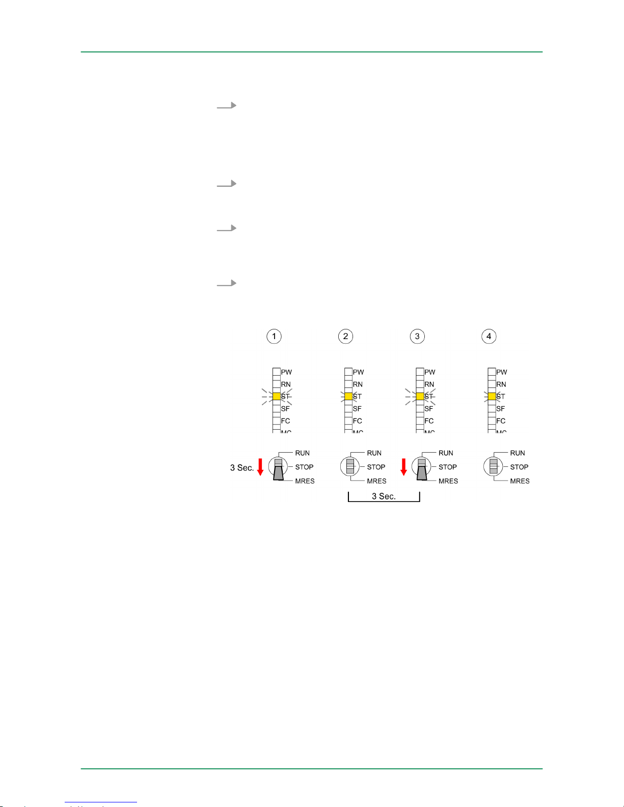
Precondition
The operating mode of the CPU is to be switched to STOP. For
this switch the operating mode switch of the CPU to "STOP".
ð
The STOP-LED is on.
Overall reset
1. Switch the operating mode switch to MRES position for about 3
seconds.
ð
The STOP-LED changes from blinking to permanently on.
2. Place the operating mode switch in the position STOP and
switch it to MRES and quickly back to STOP within a period of
less than 3 seconds.
ð
The STOP-LED blinks (overall reset procedure).
3. The overall reset has been completed when the STOP-LED is
on permanently.
ð
The STOP-LED is on. The following figure illustrates the
above procedure:
n Precondition The operating mode of the CPU is to be switched to
STOP. You may place the CPU in STOP by the menu command
‘PLC è Operating mode
’.
n Overall reset: You may request the overall reset by means of the
menu command ‘PLC è Clean/Reset’. In the dialog window you
may place your CPU in STOP state and start the overall reset if
this has not been done as yet. The STOP-LED blinks during the
overall reset procedure. When the STOP-LED is on permanently
the overall reset procedure has been completed.
If there is a project S7PROG.WLD on the MMC, the CPU attempts to
reload this project from MMC.
® The MC LED is on. When the reload has been completed the LED
expires. The operating mode of the CPU will be STOP respectively
RUN, depending on the position of the operating mode switch.
Overall reset by means
of the operating mode
switch
Overall reset by means
of the Siemens SIMATIC
Manager
Automatic reload
VIPA System 300S Deployment CPU 313-6CF13
Overall reset
HB140 | CPU-SC | 313-6CF13 | GB | 15-50 69
Page 70
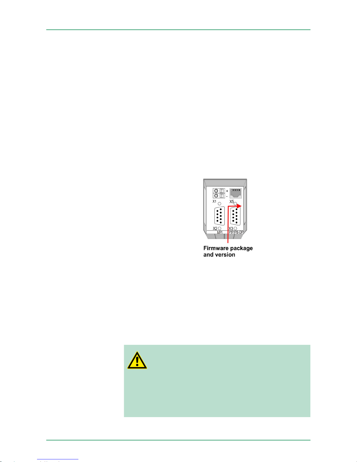
The Reset to factory setting deletes completely the internal RAM of
the CPU and resets this to delivery state. Please regard that the MPI
address is also set back to default 2!
Ä
Chapter 5.15 ‘Reset to factory
setting’ on page 73
5.14 Firmware update
n There is the opportunity to execute a firmware update for the CPU
and its components via MMC. For this an accordingly prepared
MMC must be in the CPU during the startup.
n So a firmware files can be recognized and assigned with startup,
a pkg file name is reserved for each updateable component an
hardware release, which begins with "px" and differs in a number
with six digits. The pkg file name of every updateable component
may be found at a label right down the front flap of the module.
n After PowerON and CPU STOP the CPU checks if there is a *.pkg
file on the MMC. If this firmware version is different to the existing
firmware version, this is indicated by blinking of the LEDs and the
firmware may be installed by an update request.
The latest firmware versions are to be found in the service area at
www.vipa.com. For example the following files are necessary for the
firmware update of the CPU 313-6CF13 and its components with
hardware release 1:
n 313-6CF13, Hardware release 1: Px000137.pkg
n PROFIBUS DP master: Px000064.pkg
CAUTION!
When installing a new firmware you have to be extremely
careful. Under certain circumstances you may destroy the
CPU, for example if the voltage supply is interrupted
during transfer or if the firmware file is defective. In this
case, please call the VIPA-Hotline!
Please regard that the version of the update firmware has
to be different from the existing firmware otherwise no
update is executed.
Reset to factory setting
Overview
Latest firmware at
www.vipa.com
VIPA System 300SDeployment CPU 313-6CF13
Firmware update
HB140 | CPU-SC | 313-6CF13 | GB | 15-50 70
Page 71
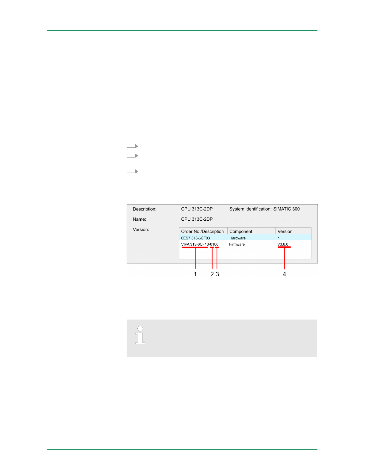
The CPU has an integrated website that monitors information about
firmware version of the SPEED7 components. The Ethernet PG/OP
channel provides the access to this web site. The CPU has an integrated website that monitors information about firmware version of
the SPEED7 components. The Ethernet PG/OP channel provides the
access to this web site ‘PLC è Assign Ethernet Address
’. After that
you may access the PG/OP channel with a web browser via the IP
address of the project engineering.
Ä
Chapter 5.11 ‘Access to the internal Web page’ on page 64
1. First establish an online connection to the CPU.
2. To show the module information you have to select ‘PLC
è Module information’ in the Siemens SIMATIC Manager.
3. Via the register ‘General’ the window with hardware and firm-
ware version may be selected.
ð
Due to software-technical reasons there is something different of the VIPA CPU 313-6CF13 to the CPU 313C-2DP
from Siemens:
1 VIPA order number (VIPA 313-6CF13)
2 Hardware release (01)
3 Internal hardware version (00)
4 Firmware version (V3.6.0)
Every register of the module information dialog is supported by the VIPA CPUs. More about these registers may
be found in the online help of the Siemens SIMATIC manager.
n Go to www.vipa.com
n Click on ‘Service è Download è Firmware’.
n Navigate via ‘System 300S è CPU’ to your CPU and download
the zip file to your PC.
n Extract the zip file and copy the extracted pkg files to your MMC.
Display the Firmware
version of the SPEED7
system via Web Site
Determine CPU firmware version with
module information
Load firmware and
transfer it to MMC
VIPA System 300S Deployment CPU 313-6CF13
Firmware update
HB140 | CPU-SC | 313-6CF13 | GB | 15-50 71
Page 72
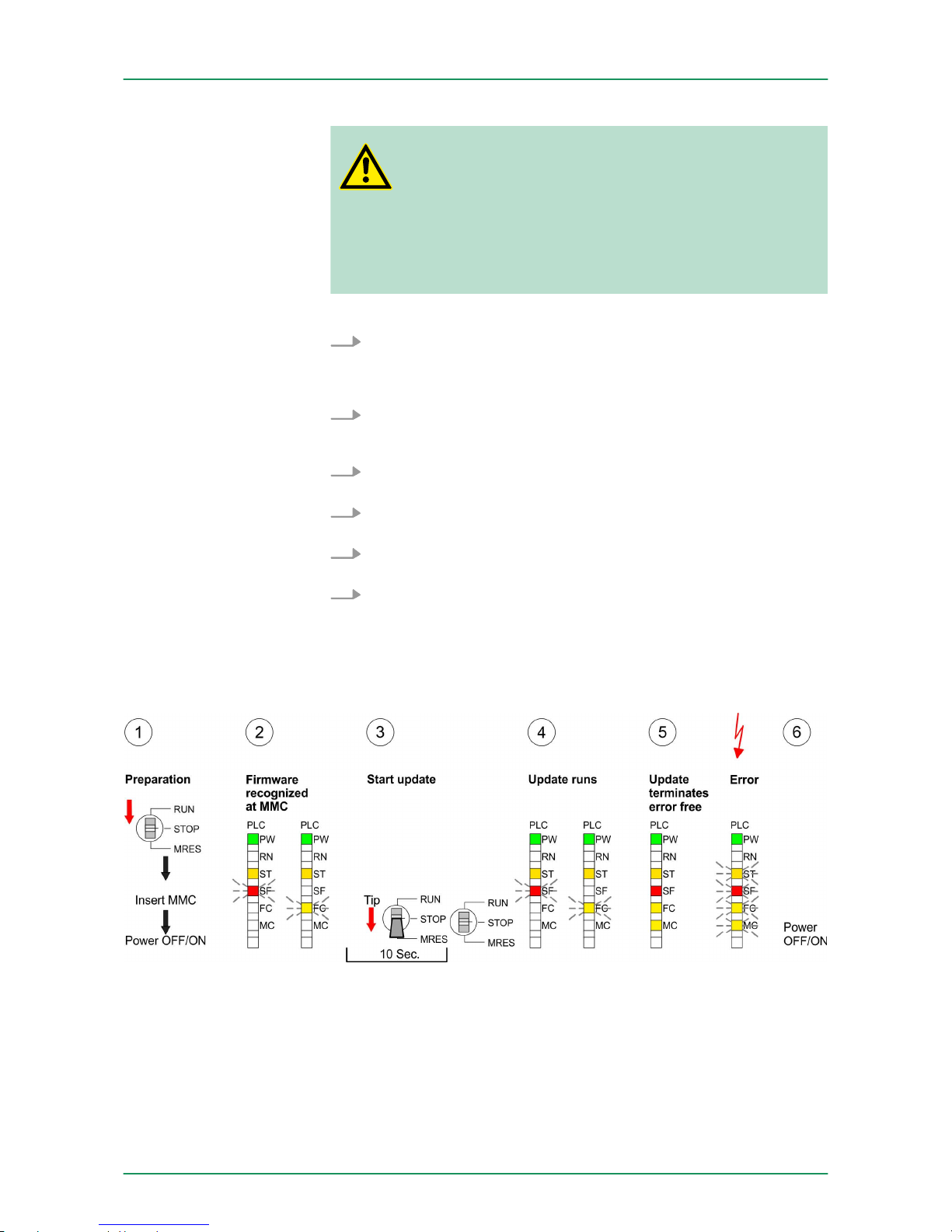
CAUTION!
With a firmware update an overall reset is automatically
executed. If your program is only available in the load
memory of the CPU it is deleted! Save your program
before executing a firmware update! After the firmware
update you should execute a "Set back to factory settings".
Ä
Chapter 5.15 ‘Reset to factory setting’
on page 73
1. Switch the operating mode switch of your CPU in position
STOP. Turn off the voltage supply. Plug the MMC with the firmware files into the CPU. Please take care of the correct plug-in
direction of the MMC. Turn on the voltage supply.
2. After a short boot-up time, the alternate blinking of the LEDs SF
and FC shows that at least a more current firmware file was
found on the MMC.
3. You start the transfer of the firmware as soon as you tip the
operating mode switch downwards to MRES within 10s.
4. During the update process, the LEDs SF and FC are alternately
blinking and MC LED is on. This may last several minutes.
5. The update is successful finished when the LEDs PW, ST, SF,
FC and MC are on. If they are blinking fast, an error occurred.
6. Turn Power OFF and ON. Now it is checked by the CPU,
whether further current firmware versions are available at the
MMC. If so, again the LEDs SF and FC flash after a short startup period. Continue with point 3.
ð
If the LEDs do not flash, the firmware update is ready. Now a
factory reset should be executed (see next page). After that
the CPU is ready for duty.
Transfer firmware from
MMC into CPU
VIPA System 300SDeployment CPU 313-6CF13
Firmware update
HB140 | CPU-SC | 313-6CF13 | GB | 15-50 72
Page 73
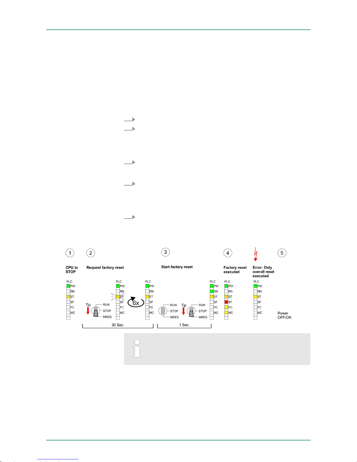
5.15 Reset to factory setting
With the following proceeding the internal RAM of the CPU is completely deleted and the CPU is reset to delivery state.
Please note that here also the IP address of the Ethernet PG/OP
channel is set to 0.0.0.0 and the MPI address is reset to the address
2!
A reset to factory setting may also be executed by the MMC-Cmd
FACTORY_RESET.
Ä
Chapter 5.19 ‘MMC-Cmd - Auto commands’
on page 77
1. Switch the CPU to STOP.
2. Push the operating mode switch down to position MRES for 30s.
Here the STOP-LED flashes. After a few seconds the stop LED
changes to static light. Now the STOP LED changes between
static light and flashing. Starting here count the static light
states.
3. After the 6. static light release the operating mode switch and tip
it downwards to MRES. Now the RUN LED lights up once. This
means that the RAM was deleted completely.
4. For the confirmation of the resetting procedure the LEDs PW,
ST, SF, FC and MC get ON. If not, the factory reset has failed
and only an overall reset was executed. In this case you can
repeat the procedure. A factory reset can only be executed if the
stop LED has static light for exactly 6 times.
5. The end of factory reset is shown by static light of the LEDs PW,
ST, SF, FC and MC. Switch the power supply off and on.
The proceeding is shown in the following Illustration:
After the firmware update you always should execute a
Reset to factory setting.
5.16 Slot for storage media
At the front of the CPU there is a slot for storage media. As external
storage medium for applications and firmware you may use a multimedia card (MMC). You can cause the CPU to load a project automatically respectively to execute a command file by means of predefined file names.
Proceeding
Overview
VIPA System 300S Deployment CPU 313-6CF13
Slot for storage media
HB140 | CPU-SC | 313-6CF13 | GB | 15-50 73
Page 74
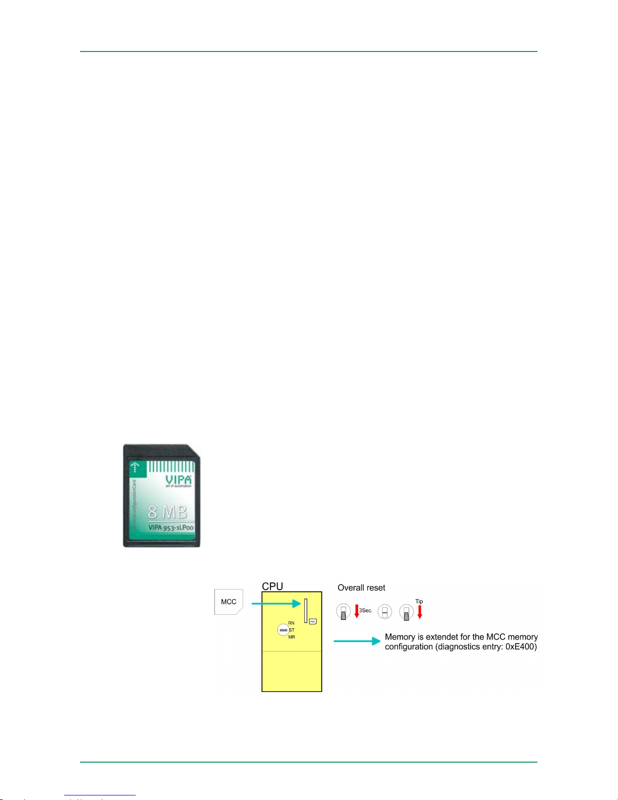
To the following times an access takes place on a storage medium:
n After overall reset
–
The CPU checks if there is a project S7PROG.WLD. If exists
the project is automatically loaded.
– The CPU checks if there is a project PROTECT.WLD with pro-
tected blocks. If exists the project is automatically loaded.
These blocks are stored in the CPU until the CPU is reset to
factory setting or an empty PROTECT.WLD is loaded
– The CPU checks if a MCC memory extension card is put. If
exists the memory extension is enabled, otherwise a memory
expansion, which was activated before, is de-activated.
n After PowerON
– The CPU checks if there is a project AUTOLOAD.WLD. If
exists an overall reset is established and the project is automatically loaded.
– The CPU checks if there is a command file with
VIPA_CMD.MMC. If exists the command file is loaded and the
containing instructions are executed.
– After PowerON and CPU STOP the CPU checks if there is a
*.pkg file (firmware file). If exists this is indicated by blinking of
the LEDs and the firmware may be installed by an update
request.
n Once in STOP
– If a storage medium is put, which contains a command file
VIPA_CMD.MMC, the command file is loaded and the containing instructions are executed.
5.17 Memory extension with MCC
There is the possibility to extend the work memory of the CPU. For
this, a MCC memory extension card is available from VIPA. The MCC
is a specially prepared MMC (Multimedia Card). By plugging the MCC
into the MCC slot and then an overall reset the according memory
expansion is released. There may only one memory expansion be
activated at one time. On the MCC there is the file memory.key. This
file may not be altered or deleted. You may use the MCC also as
"normal" MMC for storing your project.
To extend the memory, plug the MCC into the card slot at the CPU
labelled with "MCC" and execute an overall reset.
Accessing the storage
medium
Overview
Proceeding
VIPA System 300SDeployment CPU 313-6CF13
Memory extension with MCC
HB140 | CPU-SC | 313-6CF13 | GB | 15-50 74
Page 75

If the memory expansion on the MCC exceeds the maximum extendible memory range of the CPU, the maximum possible memory of the
CPU is automatically used. You may determine the recent memory
extension via the integrated web page or with the Siemens SIMATIC
Manager at Module Information - "Memory".
CAUTION!
Please regard that the MCC must remain plugged when
you’ve executed the memory expansion at the CPU. Otherwise the CPU switches to STOP after 72 hours. The
MCC cannot be exchanged with a MCC of the same
memory configuration.
When the MCC memory configuration has been taken over you may
find the diagnostic entry 0xE400 in the diagnostic buffer of the CPU.
After pulling the MCC the entry 0xE401 appears in the diagnostic
buffer, the SF LED is on and after 72 hours the CPU switches to
STOP. A reboot is only possible after plugging-in the MCC again or
after an overall reset.
The remaining time after pulling the MCC is always been shown with
the parameter MCC-Trial-Time on the web page.
After re-plugging the MCC, the SF LED extinguishes and 0xE400 is
entered into the diagnostic buffer. You may reset the memory configuration of your CPU to the initial status at any time by executing an
overall reset without MCC.
5.18
Extended know-how protection
Besides the "standard" Know-how protection the SPEED7-CPUs from
VIPA provide an "extended" know-how protection that serves a
secure block protection for accesses of 3. persons.
The standard protection from Siemens transfers also protected blocks
to the PG but their content is not displayed. But with according manipulation the Know-how protection is not guaranteed.
The "extended" know-how protection developed by VIPA offers the
opportunity to store blocks permanently in the CPU. At the "extended"
protection you transfer the protected blocks into a WLD-file named
protect.wld. By plugging the MMC and following overall reset, the
blocks in the protect.wld are permanently stored in the CPU. You may
protect OBs, FBs and FCs. When back-reading the protected blocks
into the PG, exclusively the block header are loaded. The block code
that is to be protected remains in the CPU and cannot be read.
Behavior
Overview
Standard protection
Extended protection
VIPA System 300S Deployment CPU 313-6CF13
Extended know-how protection
HB140 | CPU-SC | 313-6CF13 | GB | 15-50 75
Page 76
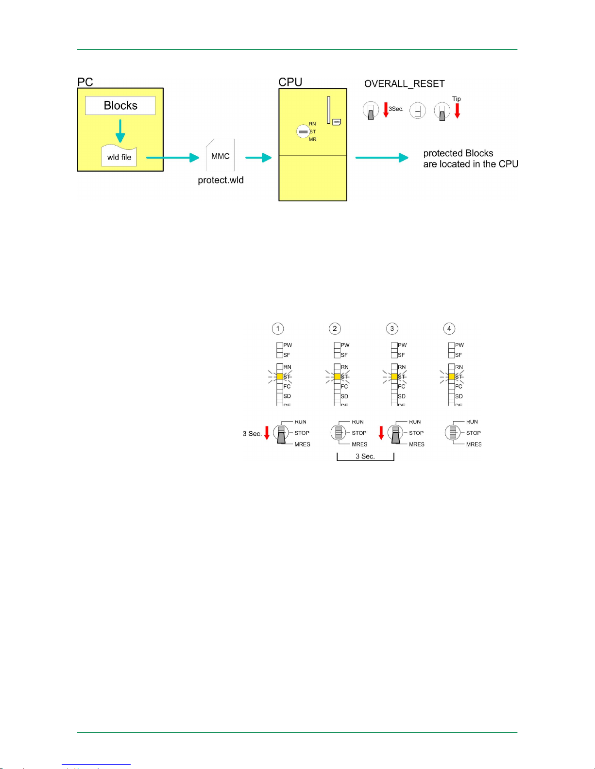
Create a new wld-file in your project engineering tool with ‘File
è Memory Card file è New
’ and rename it to "protect.wld". Transfer
the according blocks into the file by dragging them with the mouse
from the project to the file window of protect.wld.
Transfer the file protect.wld to a MMC storage module, plug the MMC
into the CPU and execute an overall reset with the following
approach:
The overall reset stores the blocks in protect.wld permanently in the
CPU protected from accesses of 3. persons.
Protected blocks are overwritten by a new protect.wld. Using a PG 3.
persons may access protected blocks but only the block header is
transferred to the PG. The block code that is to be protected remains
in the CPU and cannot be read.
Protected blocks in the RAM of the CPU may be substituted at any
time by blocks with the same name. This change remains up to next
overall reset. Protected blocks may permanently be overwritten only if
these are deleted at the protect.wld before. By transferring an empty
protect.wld from the MMC you may delete all protected blocks in the
CPU.
Protect blocks with protect.wld
Transfer protect.wld to
CPU with overall reset
Protection behavior
Change respectively
delete protected blocks
VIPA System 300SDeployment CPU 313-6CF13
Extended know-how protection
HB140 | CPU-SC | 313-6CF13 | GB | 15-50 76
Page 77

Due to the fact that reading of a "protected" block from the CPU monitors no symbol labels it is convenient to provide the "block covers" for
the end user. For this, create a project out of all protected blocks.
Delete all networks in the blocks so that these only contain the variable definitions in the according symbolism.
5.19
MMC-Cmd - Auto commands
A command file at a MMC is automatically executed under the following conditions:
n CPU is in STOP and MMC is stuck
n After each PowerON
The command
file is a text file, which consists of a command
sequence to be stored as vipa_cmd.mmc in the root directory of the
MMC. The file has to be started by CMD_START as 1. command, followed by the desired commands (no other text) and must be finished
by CMD_END as last command.
Text after the last command CMD_END e.g. comments is permissible, because this is ignored. As soon as the command file is recognized and executed each action is stored at the MMC in the log file
logfile.txt. In addition for each executed command a diagnostics entry
may be found in the diagnostics buffer.
Please regard the command sequence is to be started with
CMD_START and ended with CMD_END.
Command Description Diagnostics entry
CMD_START In the first line CMD_START is to be located. 0xE801
There is a diagnostic entry if CMD_START is
missing
0xE8FE
WAIT1SECOND Waits about 1 second. 0xE803
WEBPAGE The current web page of the CPU is stored at
the MMC as" webpage.htm".
0xE804
LOAD_PROJECT The function "Overall reset and reload from
MMC" is executed. The wld file located after the
command is loaded else "s7prog.wld" is loaded.
0xE805
SAVE_PROJECT The recent project (blocks and hardware config-
uration) is stored as "s7prog.wld" at the MMC.If
the file just exists it is renamed to "s7prog.old".
If your CPU is password protected so you have
to add this as parameter. Otherwise there is no
project written. Example: SAVE_PROJECT
password
0xE806
FACTORY_RESET Executes "factory reset". 0xE807
DIAGBUFF The current diagnostics buffer of the CPU is
stored as "diagbuff.txt" at the MMC.
0xE80B
Usage of protected
blocks
Overview
Command file
Commands
VIPA System 300S Deployment CPU 313-6CF13
MMC-Cmd - Auto commands
HB140 | CPU-SC | 313-6CF13 | GB | 15-50 77
Page 78

Command Description Diagnostics entry
SET_NETWORK IP parameters for Ethernet PG/OP channel may
be set by means of this command. The IP
parameters are to be given in the order IP
address, subnet mask and gateway in the
format x.x.x.x each separated by a comma.
Enter the IP address if there is no gateway
used.
0xE80E
CMD_END In the last line CMD_END is to be located. 0xE802
The structure of a command file is shown in the following. The corresponding diagnostics entry is put in parenthesizes.
Example 1
CMD_START
Marks the start of the command sequence (0xE801)
LOAD_PROJECT proj.wld
Execute an overall reset and load "proj.wld" (0xE805)
WAIT1SECOND
Wait ca. 1s (0xE803)
WEBPAGE
Store web page as "webpage.htm" (0xE804)
DIAGBUFF
Store diagnostics buffer of the CPU as "diagbuff.txt"
(0xE80B)
CMD_END
Marks the end of the command sequence (0xE802)
... arbitrary text ...
Text after the command CMD_END is not evaluated.
Example 2
CMD_START
Marks the start of the command sequence (0xE801)
LOAD_PROJECT proj2.wld
Execute an overall reset and load "proj2.wld" (0xE805)
WAIT1SECOND
Wait ca. 1s (0xE803)
WAIT1SECOND
Wait ca. 1s (0xE803)
IP parameter (0xE80E)
SET_NETWORK 172.16.129.210,255.255.224.0,172.16.129.210
WAIT1SECOND
Wait ca. 1s (0xE803)
WAIT1SECOND
Wait ca. 1s (0xE803)
WEBPAGE
Store web page as "webpage.htm" (0xE804)
DIAGBUFF
Store diagnostics buffer of the CPU as "diagbuff.txt"
(0xE80B)
CMD_END
Marks the end of the command sequence (0xE802)
... arbitrary text ...
Text after the command CMD_END is not evaluated.
The parameters IP address, subnet mask and gateway
may be received from the system administrator.
Enter the IP address if there is no gateway used.
Examples
VIPA System 300SDeployment CPU 313-6CF13
MMC-Cmd - Auto commands
HB140 | CPU-SC | 313-6CF13 | GB | 15-50 78
Page 79
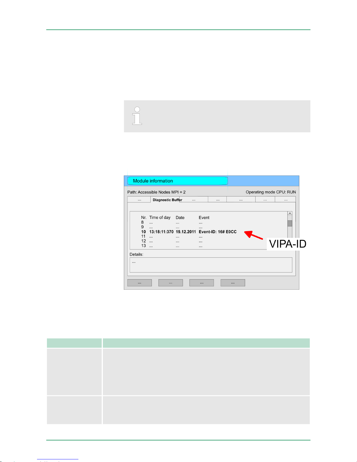
5.20 VIPA specific diagnostic entries
You may read the diagnostic buffer of the CPU via the Siemens
SIMATIC Manager. Besides of the standard entries in the diagnostic
buffer, the VIPA CPUs support some additional specific entries in
form of event-IDs.
The current content of the diagnostics buffer is stored at the memory
card by means of the CMD DIAGBUFF.
Every register of the module information is supported by
the VIPA CPUs. More information may be found at the
online help of the Siemens SIMATIC Manager.
To monitor the diagnostic entries you choose the option ‘PLC
è Module Information
’ in the Siemens SIMATIC Manager. Via the
register "Diagnostic Buffer" you reach the diagnostic window:
The diagnosis is independent from the operating mode of the CPU.
You may store a max. of 100 diagnostic entries in the CPU. The following page shows an overview of the VIPA specific Event-IDs.
Overview of the Event-IDs
Event-ID Description
0x115C Vendor-specific interrupt (OB 57) at EtherCAT
OB: OB number (57)
ZInfo1: Logical address of the slave, which has released the interrupt
ZInfo2: Interrupt type
ZInfo3: Reserved
0xE003 Error on accessing the periphery
ZInfo1: Periphery address
ZInfo2: Slot
Entries in the diagnostic buffer
Monitoring the diagnostic entries
VIPA System 300S Deployment CPU 313-6CF13
VIPA specific diagnostic entries
HB140 | CPU-SC | 313-6CF13 | GB | 15-50 79
Page 80

Event-ID Description
0xE004 Multiple parametrization of a periphery address
ZInfo1: Periphery address
ZInfo2: Slot
0xE005 Internal error - Please contact the VIPA Hotline!
0xE006 Internal error - Please contact the VIPA Hotline!
0xE007 Configured in-/output bytes do not fit into periphery area
0xE008 Internal error - Please contact the VIPA Hotline!
0xE009 Error on accessing the standard backplane bus
0xE010 There is a undefined module at the backplane bus
ZInfo2: Slot
ZInfo3: Type ID
0xE011 Master project engineering at slave CPU not possible or wrong slave
configuration
0xE012 Error at parametrization
0xE013 Error at shift register access to standard bus digital modules
0xE014 Error at Check_Sys
0xE015 Error at access to the master
ZInfo2: Slot of the master (32=page frame master)
0xE016 Maximum block size at master transfer exceeded
ZInfo1: Periphery address
ZInfo2: Slot
0xE017 Error at access to integrated slave
0xE018 Error at mapping of the master periphery
0xE019 Error at standard back plane bus system recognition
0xE01A Error at recognition of the operating mode (8 / 9 bit)
0xE01B Error - Maximum number of plug-in modules exceeded
0xE020 Error - Interrupt information is not defined
0xE030 Error of the standard bus
0xE033 Internal error - Please contact the VIPA Hotline!
0xE0B0 SPEED7 is not stoppable
(Probably undefined BCD value at timer)
0xE0C0 Not enough space in work memory for storing code block (block size
exceeded)
0xE0CB Error at SSL access
ZInfo1: 4=SSL wrong, 5=SubSSL wrong, 6=Index wrong
ZInfo2: SSL-ID
ZInfo3: Index
VIPA System 300SDeployment CPU 313-6CF13
VIPA specific diagnostic entries
HB140 | CPU-SC | 313-6CF13 | GB | 15-50 80
Page 81

Event-ID Description
0xE0CC Communication error MPI / Serial
ZInfo1: Code
1: Wrong priority
2: Buffer overflow
3: Frame format error
4: Wrong SSL request (SSL-ID not valid)
5: Wrong SSL request (SSL-SubID not valid)
6: Wrong SSL request (SSL-Index not valid)
7: Wrong value
8: Wrong RetVal
9: Wrong SAP
10: Wrong connection type
11: Wrong sequence number
12: Faulty block number in the telegram
13: Faulty block type in the telegram
14: Inactive function
15: Wrong size in the telegram
20: Error writing to memory card
90: Faulty buffer size
98: Unknown error
99: Internal error
0xE0CD Error at DP-V1 job management
0xE0CE Error: Timeout at sending of the i-slave diagnostics
0xE0CF Timeout at loading of a new HW configuration (timeout: 39 seconds)
0xE100 Memory card access error
0xE101 Memory card error file system
0xE102 Memory card error FAT
0xE104 Memory card error at saving
0xE200 Memory card writing finished (Copy Ram2Rom)
0xE210 Memory card reading finished (reload after overall reset)
0xE21E Memory card reading: Error at reload (after overall reset), file "Protect.wld"
too big
0xE21F Memory card reading: Error at reload (after overall reset), file read error, out
of memory
0xE300 Internal flash writing finished (Copy Ram2Rom)
0xE310 Internal flash writing finished (reload after battery failure)
0xE311 Internal flash fx0000yy.wld file too big, load failure
VIPA System 300S Deployment CPU 313-6CF13
VIPA specific diagnostic entries
HB140 | CPU-SC | 313-6CF13 | GB | 15-50 81
Page 82

Event-ID Description
0xE400 Memory card with the option memory expansion was plugged
0xE401 Memory card with the option memory expansion was removed
0xE402 The PROFIBUS DP master functionality is disabled. The interface acts fur-
ther as MPI interface
0xE403 The PROFIBUS DP slave functionality is disabled. The interface acts further
as MPI interface
0xE500 Memory management: Deleted block without corresponding entry in Block
List
ZInfo2: BlockType
ZInfo3: BlockNo
0xE604 Multiple parametrization of a periphery address for Ethernet PG/OP channel
ZInfo1: Periphery address
ZInfo3:
0: Periphery address is input, 1: Periphery address is output
0xE701 Internal error - Please contact the VIPA Hotline!
0xE703 Internal error - Please contact the VIPA Hotline!
0xE720 Internal error - Please contact the VIPA Hotline!
0xE721 Internal error - Please contact the VIPA Hotline!
0xE801 CMD - Auto command: CMD_START recognized and successfully executed
0xE802 CMD - Auto command: CMD_End recognized and successfully executed
0xE803 CMD - Auto command: WAIT1SECOND recognized and successfully exe-
cuted
0xE804 CMD - Auto command: WEBPAGE recognized and successfully executed
0xE805 CMD - Auto command: LOAD_PROJECT recognized and successfully exe-
cuted
0xE806 CMD - Auto command: SAVE_PROJECT
Zinfo3: 0x0000: SAVE_PROJECT recognized and successfully executed
Zinfo3: 0x8000: Error during SAVE_PROJECT e.g. wrong password
0xE807 CMD - Auto command: FACTORY_RESET recognized and successfully
executed
0xE80B CMD - Auto command: DIAGBUFF recognized and successfully executed
0xE80E CMD - Auto command: SET_NETWORK recognized and successfully exe-
cuted
0xE816 CMD - Auto command: SAVE_PROJECT: Error - CPU has been reset - no
wld file was created.
VIPA System 300SDeployment CPU 313-6CF13
VIPA specific diagnostic entries
HB140 | CPU-SC | 313-6CF13 | GB | 15-50 82
Page 83

Event-ID Description
0xE8FB CMD - Auto command: Error: Initialization of the Ethernet PG/OP channel
by means of SET_NETWORK is faulty
0xE8FC CMD - Auto command: Error: Some IP parameters missing in SET_NET-
WORK
0xE8FE CMD - Auto command: Error: CMD_START missing
0xE8FF CMD - Auto command: Error: Error while reading CMD file (memory card
error)
0xE901 Check sum error
0xEA00 Internal error - Please contact the VIPA Hotline!
0xEA01 Internal error - Please contact the VIPA Hotline!
0xEA02 SBUS: Internal error (internal plugged sub module not recognized)
ZInfo1: Internal slot
0xEA03 SBUS: Communication error CPU - PROFINET I/O controller:
ZInfo1: Slot
ZInfo2: Status
(0: OK, 1: ERROR, 2: BUSY, 3: TIMEOUT, 4: LOCKED, 5: UNKNOWN)
0xEA04 SBUS: Multiple parametrization of a periphery address
ZInfo1: Periphery address
ZInfo2: Slot
ZInfo3: Data width
0xEA05 Internal error - Please contact the VIPA Hotline!
0xEA07 Internal error - Please contact the VIPA Hotline!
0xEA08 SBUS: Parametrized input data width unequal to plugged input data width
ZInfo1: Parametrized input data width
ZInfo2: Slot
ZInfo3: Input data width of the plugged module
0xEA09 SBUS: Parametrized output data width unequal to plugged output data width
ZInfo1: Parametrized output data width
ZInfo2: Slot
ZInfo3: Output data width of the plugged module
0xEA10 SBUS: Input periphery address outside the periphery area
ZInfo1: Periphery address
ZInfo2: Slot
ZInfo3: Data width
VIPA System 300S Deployment CPU 313-6CF13
VIPA specific diagnostic entries
HB140 | CPU-SC | 313-6CF13 | GB | 15-50 83
Page 84

Event-ID Description
0xEA11 SBUS: Output periphery address outside the periphery area
ZInfo1: Periphery address
ZInfo2: Slot
ZInfo3: Data width
0xEA12 SBUS: Error at writing record set
ZInfo1: Slot
ZInfo2: Record set number
ZInfo3: Record set length
0xEA14 SBUS: Multiple parametrization of a periphery address (diagnostics
address)
ZInfo1: Periphery address
ZInfo2: Slot
ZInfo3: Data width
0xEA15 Internal error - Please contact the VIPA Hotline!
0xEA18 SBUS: Error at mapping of the master periphery
ZInfo2: Slot of the master
0xEA19 Internal error - Please contact the VIPA Hotline!
0xEA20 Error - RS485 interface is not pre-set to PROFIBUS DP master bus a
PROFIBUS DP master is configured.
0xEA21 Error - Configuration RS485 interface X2/X3:
PROFIBUS DP master is configured but missing
ZInfo2: Interface x
0xEA22 Error - RS485 interface X2 - Value exceeds the limits
ZInfo: Configured value of X2
0xEA23 Error - RS485 interface X3 - Value exceeds the limits
ZInfo: Configured value of X3
0xEA24 Error - Configuration RS485 interface X2/X3:
Interface/protocol missing, default settings are used
ZInfo2: Configured value for X2
ZInfo3: Configured value for X3
0xEA30 Internal error - Please contact the VIPA Hotline!
0xEA40 Internal error - Please contact the VIPA Hotline!
0xEA41 Internal error - Please contact the VIPA Hotline!
0xEA50 Error - PROFINET configuration
ZInfo1: User slot of the PROFINET I/O controller
ZInfo2: IO-Device-No.
ZInfo3: IO-Device slot
VIPA System 300SDeployment CPU 313-6CF13
VIPA specific diagnostic entries
HB140 | CPU-SC | 313-6CF13 | GB | 15-50 84
Page 85

Event-ID Description
0xEA51 Error - There is no PROFINET IO controller at the configured slot
ZInfo1: User slot of the PROFINET I/O controller
ZInfo2: Recognized ID at the configured slot
0xEA53 Error - PROFINET configuration - There are too many PROFINET IO
devices configured
ZInfo1: Number of configured devices
ZInfo2: Slot
ZInfo3: Maximum possible number of devices
0xEA54 Error - PROFINET IO controller reports multiple parametrization of a
periphery address
ZInfo1: Periphery address
ZInfo2: User slot of the PROFINET I/O controller
ZInfo3: Data width
0xEA61 ... 0xEA63 Internal error - Please contact the VIPA Hotline!
0xEA64 PROFINET/EtherCAT CP
Configuration error: Zinfo1:
Bit 0: Too many devices
Bit 1: Too many devices per ms
Bit 2: Too many input bytes per ms
Bit 3: Too many output bytes per ms
Bit 4: Too many input bytes per device
Bit 5: Too many output bytes per device
Bit 6: Too many productive connections
Bit 7: Too many input bytes in the process image
Bit 8: Too many output bytes in the process image
Bit 9: Configuration not available
Bit 10: Configuration not valid
Bit 11: Cycle time too small
Bit 12: Cycle time too big
Bit 13: Not valid device number
Bit 14: CPU is configured as I device
Bit 15: Obtain an IP address in a different way is not supported for the IP
address of the controller
0xEA65 Internal error - Please contact the VIPA Hotline!
VIPA System 300S Deployment CPU 313-6CF13
VIPA specific diagnostic entries
HB140 | CPU-SC | 313-6CF13 | GB | 15-50 85
Page 86

Event-ID Description
0xEA66 PROFINET IO controller
Error in communication stack
PK: Rackslot
OBNr: StackError.Service
DatId: StackError.DeviceRef
ZInfo1: StackError.Error.Code
ZInfo2: StackError.Error.Detail
ZInfo3: StackError.Error.AdditionalDetail
<< 8 + StackError.Error.AreaCode
0xEA67 Error - PROFINET IO controller - reading record set
PK: Error type
0: DATA_RECORD_ERROR_LOCAL
1: DATA_RECORD_ERROR_STACK
2: DATA_RECORD_ERROR_REMOTE
OBNr: PROFINET IO controller slot
DatId: Device-No.
ZInfo1: Record set number
ZInfo2: Record set handle
ZInfo3: Internal error code for service purposes
0xEA68 Error - PROFINET IO controller - writing record set
PK: Error type
0: DATA_RECORD_ERROR_LOCAL
1: DATA_RECORD_ERROR_STACK
2: DATA_RECORD_ERROR_REMOTE
OBNo: PROFINET IO controller slot
DatId: Device-No.
ZInfo1: Record set number
ZInfo2: Record set handle
ZInfo3: Internal error code for service purposes
0xEA69 Internal error - Please contact the VIPA Hotline!
0xEA6A PROFINET IO controller
Service error in communication stack
PK: Rackslot
OBNo: ServiceIdentifier
DatId: 0
ZInfo1: ServiceError.Code
ZInfo2: ServiceError.Detail
ZInfo3: StackError.Error.AdditionalDetail
VIPA System 300SDeployment CPU 313-6CF13
VIPA specific diagnostic entries
HB140 | CPU-SC | 313-6CF13 | GB | 15-50 86
Page 87

Event-ID Description
0xEA6B PROFINET IO controller
Vendor ID mismatch
PK: Rackslot
OBNo: PLC Mode
DatId: 0
ZInfo1: Device ID
ZInfo2: -
ZInfo3: -
0xEA6C PROFINET IO controller
Device ID mismatch
PK: Rackslot
OBNo: PLC Mode
DatId: 0
ZInfo1: Device ID
ZInfo2: -
ZInfo3: -
0xEA6D PROFINET IO controller
No empty name
PK: Rackslot
OBNo: PLC Mode
DatId: 0
ZInfo1: Device ID
ZInfo2: -
ZInfo3: -
0xEA6E PROFINET IO controller
RPC response missing
PK: Rackslot
OBNo: PLC Mode
DatId: 0
ZInfo1: Device ID
ZInfo2: -
ZInfo3: -
VIPA System 300S Deployment CPU 313-6CF13
VIPA specific diagnostic entries
HB140 | CPU-SC | 313-6CF13 | GB | 15-50 87
Page 88

Event-ID Description
0xEA6F PROFINET IO controller
PN module mismatch
PK: Rackslot
OBNo: PLC-Mode
DatId: 0
ZInfo1: Device ID
ZInfo2: -
ZInfo3: -
0xEA97 Storage error SBUS service channel
ZInfo3 = Slot
0xEA98 Timeout at waiting for reboot of a SBUS module (server)
0xEA99 Error at file reading via SBUS
0xEAA0 Emac Error occurred
OBNo: Current PLC mode
ZInfo1: Diagnostics address of the master / controller
ZInfo2:
0: None Rx queue is full
1: No send buffer available
2: Send stream was cut off; sending failed
3: Exhausted retries
4: No receive buffer available in Emac DMA
5: Emac DMA transfer aborted
6: Queue overflow
7: Unexpected frame received
ZInfo3: Number of errors, which occurred
0xEAB0 Link mode not valid
OBNo: Current PLC mode
ZInfo1: Diagnostics address master / controller
Zinfo2: Current LinkMode
0x01: 10Mbit full-duplex
0x02: 100Mbit half-duplex
0x03: 100Mbit full-duplex
0x05: 10Mbit half-duplex
0xFF: Link mode not defined
0xEB03 SLIO error on IO mapping
0xEB10 SLIO error: Bus error
ZInfo1: Type of error
0x82: ErrorAlarm
VIPA System 300SDeployment CPU 313-6CF13
VIPA specific diagnostic entries
HB140 | CPU-SC | 313-6CF13 | GB | 15-50 88
Page 89

Event-ID Description
0xEB20 SLIO error: Interrupt information undefined
0xEB21 SLIO error on accessing the configuration data
0xEC03 EtherCAT: Configuration error
ZInfo1: Errorcode
1: NUMBER_OF_SLAVES_NOT_SUPPORTED
2: SYSTEM_IO_NR_INVALID
3: INDEX_FROM_SLOT_ERROR
4: MASTER_CONFIG_INVALID
5: MASTER_TYPE_ERROR
6: SLAVE_DIAG_ADDR_INVALID
7: SLAVE_ADDR_INVALID
8: SLAVE_MODULE_IO_CONFIG_INVALID
9: LOG_ADDR_ALREADY_IN_USE
10: NULL_PTR_CHECK_ERROR
11: IO_MAPPING_ERROR
12: ERROR
0xEC04 EtherCAT: Multiple configuration of a periphery address
ZInfo1: Periphery address
ZInfo2: Slot
0xEC10 EtherCAT: Restoration bus with its slaves
OB start Info (Local data) StartEvent and Eventclass: 0xEC10
DatID:
0xXXYY:
XX=0x54 with input address in ZInfo1,
XX=0x55 with output address.
YY=0x00 Station not available,
YY=0x01 Station available (process data)
ZInfo1: 0xXXYY (XX=OldState, YY=NewState)
ZInfo2: Diagnostics address of the master
ZInfo3: Number of stations, which are not in the same state as the master
(> 0)
VIPA System 300S Deployment CPU 313-6CF13
VIPA specific diagnostic entries
HB140 | CPU-SC | 313-6CF13 | GB | 15-50 89
Page 90

Event-ID Description
0xEC11 EtherCAT: Restoration bus with missing slaves
OB start Info (Local data) StartEvent and Eventclass: 0xEC11
DatID:
0xXXYY:
XX=0x54 with input address in ZInfo1,
XX=0x55 with output address.
YY=0x00 Station not available,
YY=0x01 Station available (process data)
ZInfo1: 0xXXYY (XX=OldState, YY=NewState)
ZInfo2: Diagnostics address of the master
ZInfo3: Number of stations, which are not in the same state as the master
(> 0)
0xEC12 EtherCAT: restoration slave
OB start Info (Local data) StartEvent and Eventclass: 0xEC12
DatID:
0xXXYY:
XX=0x54 with input address in ZInfo1,
XX=0x55 with output address.
YY=0x00 Station not available,
YY=0x01 Station available (process data)
ZInfo1: 0xXXYY (XX=OldState, YY=NewState)
ZInfo2: Diagnostics of the Station
ZInfo3: AlStatusCode
0xEC30 EtherCAT: Topology OK
OB start Info (Local data) StartEvent and Eventclass: 0xEC30
ZInfo2: Diagnostics address of the master
0xEC50 EtherCAT: DC not in Sync
ZInfo1: Diagnostics address of the master
0xED10 EtherCAT: Bus failure
OB start Info (Local data) StartEvent and Eventclass: 0xED10
DatID:
0xXXYY:
XX=0x54 with input address in ZInfo1,
XX=0x55 with output address.
YY=0x00 Station not available,
YY=0x01 Station available (process data)
ZInfo1: 0xXXYY (XX=OldState, YY=NewState)
ZInfo2: Diagnostics address of the master
ZInfo3: Number of stations, which are not in the same state as the master
VIPA System 300SDeployment CPU 313-6CF13
VIPA specific diagnostic entries
HB140 | CPU-SC | 313-6CF13 | GB | 15-50 90
Page 91

Event-ID Description
0xED12 EtherCAT: Failure slave
OB start Info (Local data) StartEvent and Eventclass: 0xED12
DatID:
0xXXYY:
XX=0x54 with input address in ZInfo1,
XX=0x55 with output address.
YY=0x00 Station not available,
YY=0x01 Station available (process data)
ZInfo1: 0xXXYY (XX=OldState, YY=NewState)
ZInfo2: Diagnostics of the Station
ZInfo3: AlStatusCode
0xED20 EtherCAT: Bus state change without calling OB86
OB start Info (Local data) StartEvent and Eventclass: 0xED20
DatID:
0xXXYY:
XX=0x54 with input address in ZInfo1,
XX=0x55 with output address.
YY=0x00 Station not available,
YY=0x01 Station available (process data)
ZInfo1: 0xXXYY (XX=OldState, YY=NewState)
ZInfo2: Diagnostics address of the master
ZInfo3: Number of stations, which are not in the same state as the master
0xED21 EtherCAT: error in bus state change
OB: 0x00
PK: 0x00
DatID:
0xXXYY:
XX=0x54 with input address in ZInfo1,
XX=0x55 with output address.
YY=0x00 Station not available,
YY=0x01 Station available (process data)
ZInfo1: 0xXXYY (XX = current state, YY = expected state)
ZInfo2: Diagnostics address of the master
ZInfo3: ErrorCode:
0x0008: Busy
0x000B: Invalid Parameter
0x000E: Invalid State
0x0010: Timeout
VIPA System 300S Deployment CPU 313-6CF13
VIPA specific diagnostic entries
HB140 | CPU-SC | 313-6CF13 | GB | 15-50 91
Page 92

Event-ID Description
0xED22 EtherCAT: Bus state change without calling OB86
OB start Info (Local data) StartEvent and Eventclass: 0xED22
DatID:
0xXXYY:
XX=0x54 with input address in ZInfo1,
XX=0x55 with output address.
YY=0x00 Station not available,
YY=0x01 Station available (process data)
ZInfo1: 0xXXYY (XX=OldState, YY=NewState)
ZInfo2: Diagnostics of the Station
ZInfo3: AlStatusCode
0xED30 EtherCAT: Topology Mismatch
OB start Info (Local data) StartEvent and Eventclass: 0xED30
ZInfo2: Diagnostics address of the master
0xED31 EtherCAT: Interrupt Queue Overflow
OB start Info (Local data) StartEvent and Eventclass: 0xED31
ZInfo2: Diagnostics address of the master
0xED40 ... 0xED4F Internal error - Please contact the VIPA Hotline!
0xED50 EtherCAT: DC not in Sync
ZInfo1: Diagnostics address of the master
0xED60 EtherCAT: Diagnostics buffer CP:
Slave state change
PK: 0
OB: PLC-Mode
DatID 1/2: 0
ZInfo1: 0x00YY:
YY: New EtherCAT state of the slave
ZInfo2: EtherCAT station address
ZInfo3: AlStatusCode (EtherCAT specific error code)
VIPA System 300SDeployment CPU 313-6CF13
VIPA specific diagnostic entries
HB140 | CPU-SC | 313-6CF13 | GB | 15-50 92
Page 93

Event-ID Description
0xED61 EtherCAT: Diagnostics buffer CP:
CoE emergency
PK: EtherCAT station address (low byte)
OB: EtherCAT station address (high byte)
DatID 1/2: Error code
ZInfo1: 0xYYZZ:
YY: Error register
ZZ: MEF byte 1
ZInfo 2: 0xYYZZ:
YY: MEF byte 2
ZZ: MEF byte 3
ZInfo3: 0xYYZZ:
YY: MEF byte 4
ZZ: MEF byte 5
0xED62 EtherCAT: Diagnostics buffer CP:
Error on SDO access during state change
PK: EtherCAT station address (low byte)
OB: EtherCAT station address (high byte)
DatID 1/2: Subindex
ZInfo1: Index
ZInfo2: SDO error code (high word)
ZInfo3: SDO error code (low word)
0xED70 EtherCAT: Diagnostics buffer CP:
Twice HotConnect group found
PK: 0
OB: PLC-Mode
DatID 1/2: 0
ZInfo1: Diagnostics address of the master
ZInfo2: EtherCAT station address
ZInfo3: 0
0xEE00 Additional information at UNDEF_OPCODE
0xEE01 Internal error - Please contact the VIPA Hotline!
0xEEEE CPU was completely overall reset, since after PowerON the start-up could
not be finished.
0xEF11 ... 0xEF13 Internal error - Please contact the VIPA Hotline!
VIPA System 300S Deployment CPU 313-6CF13
VIPA specific diagnostic entries
HB140 | CPU-SC | 313-6CF13 | GB | 15-50 93
Page 94

Event-ID Description
0xEFFF Internal error - Please contact the VIPA Hotline!
PK: C-Source module number | DatID: Line number
5.21 Control and monitoring of variables with test functions
For troubleshooting purposes and to display the status of certain variables you can access certain test functions via the menu item Debug
of the Siemens SIMATIC Manager.
n The status of the operands and the RLO can be displayed by
means of the test function ‘Debug è Monitor
’.
n The status of the operands and the RLO can be displayed by
means of the test function ‘PLC è Monitor/Modify Variables’.
This test function displays the current status and the RLO of the different operands while the program is being executed. It is also possible to enter corrections to the program.
When using the test function "Monitor" the PLC must be in
RUN mode!
The processing of the states may be interrupted by means of jump
commands or by timer and process-related interrupts. The interruption of the processing of statuses does not change the execution of
the program. It only shows that the data displayed is no longer valid.
At the breakpoint the CPU stops collecting data for the status display
and instead of the required data it only provides the PG with data
containing the value 0. For this reason, jumps or time and process
alarms can result in the value displayed during program execution
remaining at 0 for the items below:
n the result of the logical operation RLO
n Status / AKKU 1
n AKKU 2
n Condition byte
n absolute memory address SAZ. In this case SAZ is followed by a
"?".
This test function returns the condition of a selected operand (inputs,
outputs, flags, data word, counters or timers) at the end of program
execution. This information is obtained from the process image of the
selected operands. During the "processing check" or in operating
mode STOP the periphery is read directly from the inputs. Otherwise
only the process image of the selected operands is displayed.
Overview
‘Debug è Monitor
’
‘PLC
è Monitor/Modify
Variables’
VIPA System 300SDeployment CPU 313-6CF13
Control and monitoring of variables with test functions
HB140 | CPU-SC | 313-6CF13 | GB | 15-50 94
Page 95

n Control of outputs
–
It is possible to check the wiring and proper operation of output
modules.
– You can set outputs to any desired status with or without a
control program. The process image is not modified but outputs are no longer inhibited.
n Control of variables
– The following variables may be modified: I, Q, M, T, C and D.
– The process image of binary and digital operands is modified
independently of the operating mode of the CPU.
– When the operating mode is RUN the program is executed
with the modified process variable. When the program continues they may, however, be modified again without notification.
– Process variables are controlled asynchronously to the execu-
tion sequence of the program.
VIPA System 300S Deployment CPU 313-6CF13
Control and monitoring of variables with test functions
HB140 | CPU-SC | 313-6CF13 | GB | 15-50 95
Page 96

6 Deployment I/O periphery
6.1 Overview
At the 313-6CF13 the connectors for digital in-/output and technological functions are integrated to a 2tier casing.
The project engineering takes place in the Siemens SIMATIC manager as CPU 313C-2DP from Siemens (6ES7 313-6CF03-0AB0
V2.6). Here the CPU 313-6CF13 is parameterized by the "Properties"
dialog of the CPU 313C-2DP. For parameterization of the digital I/O
periphery and the technological functions the corresponding submodule of the CPU 313C-2DP may be used.
The integrated I/Os of the 313-6CF13 may be used for technological
functions or as standard I/Os. Technological functions and standard I/
Os may be used simultaneously with appropriate hardware. Read
access to inputs used by technological functions is possible. Write
access to used outputs is not possible.
Up to 3 channels may be parameterized as technological function.
The parameterization of the appropriate channel is made in the hardware configurator by the count submodule of the CPU 313C-2DP.
There are the following technological functions:
n Continuous count
n Single count
n Periodic count
n Frequency measurement
n Pulse width modulation (PWM)
The controlling of the corresponding counter mode happens by
means of the SFB COUNT (SFB 47) of the user program.
Hardware
Project engineering
I/O periphery
Technological functions
VIPA System 300SDeployment I/O periphery
Overview
HB140 | CPU-SC | 313-6CF13 | GB | 15-50 96
Page 97
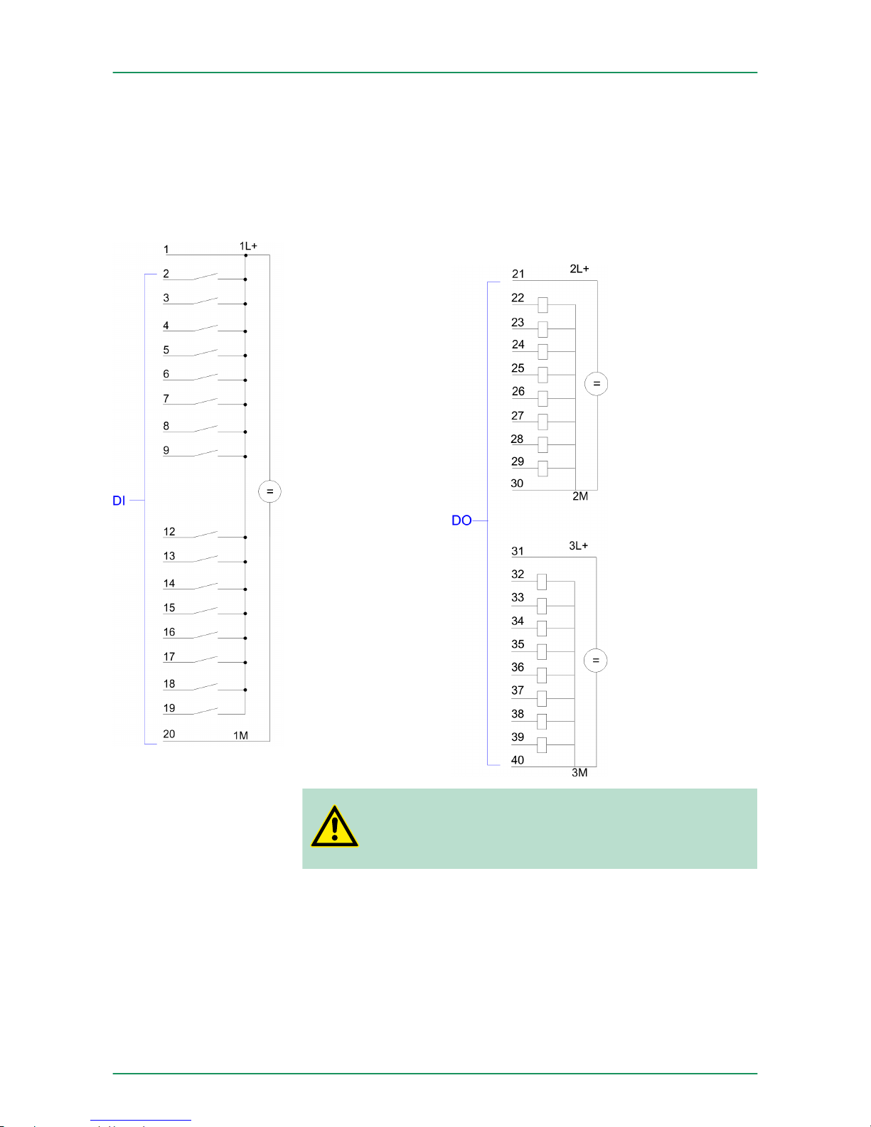
6.2 In-/Output area CPU 313-6CF13
The CPU 313-6CF13 has the following digital in- and output ranges
integrated in one casing:
n Digital Input: 16xDC 24V, with interrupt capability
n Digital Output: 16xDC 24V, 0.5A
n Technological functions: 3 channels
X11:
CAUTION!
Please regard that the voltage at an output channel is
always £ the supply voltage connected to L+.
Overview
VIPA System 300S Deployment I/O periphery
In-/Output area CPU 313-6CF13
HB140 | CPU-SC | 313-6CF13 | GB | 15-50 97
Page 98
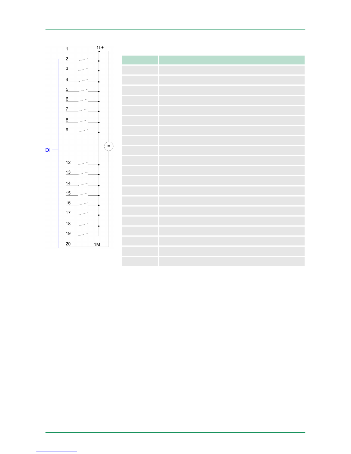
Pin assignment X11: DI
Pin Assignment
1 1L+ Power supply +DC 24V
2 I+0.0 / Channel 0 (A) / Pulse
3 I+0.1 / Channel 0 (B) / Direction
4 I+0.2 / Channel 0 HW gate
5 I+0.3 / Channel 1 (A) / Pulse
6 I+0.4 / Channel 1 (B) / Direction
7 I+0.5 / Channel 1 HW gate
8 I+0.6 / Channel 2 (A) / Pulse
9 I+0.7 / Channel 2 (B) / Direction
10 not used
11 not used
12 I+1.0 / Channel 2 HW gate
13 I+1.1
14 I+1.2
15 I+1.3
16 I+1.4 / Channel 0 Latch
17 I+1.5 / Channel 1 Latch
18 I+1.6 / Channel 2 Latch
19 I+1.7
20 Ground 1M DI
VIPA System 300SDeployment I/O periphery
In-/Output area CPU 313-6CF13
HB140 | CPU-SC | 313-6CF13 | GB | 15-50 98
Page 99
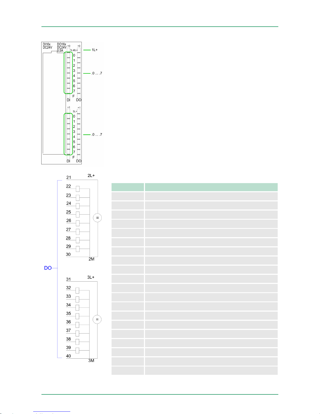
Status indication X11: DI
n 1L+
–
LED (green)
Supply voltage available for DI
n .0 ... .7
– LEDs (green)
I+0.0 ... I+0.7
I+1.0 ... I+1.7
Starting with ca. 15V the signal "1" at the input is recognized
and the according LED is activated
Pin assignment X11: DO
Pin Assignment
21 2L+ Power supply +DC 24V
22 O+0.0 / Channel 0 Output
23 O+0.1 / Channel 1 Output
24 Q+0.2 / Channel 2 Output
25 Q+0.3
26 Q+0.4
27 Q+0.5
28 Q+0.6
29 Q+0.7
30 Ground 2M DO
31 3L+ Power supply +DC 24V
32 Q+1.0
33 Q+1.1
34 Q+1.2
35 Q+1.3
36 Q+1.4
37 Q+1.5
38 Q+1.6
39 Q+1.7
40 Ground 3M DO
VIPA System 300S Deployment I/O periphery
In-/Output area CPU 313-6CF13
HB140 | CPU-SC | 313-6CF13 | GB | 15-50 99
Page 100
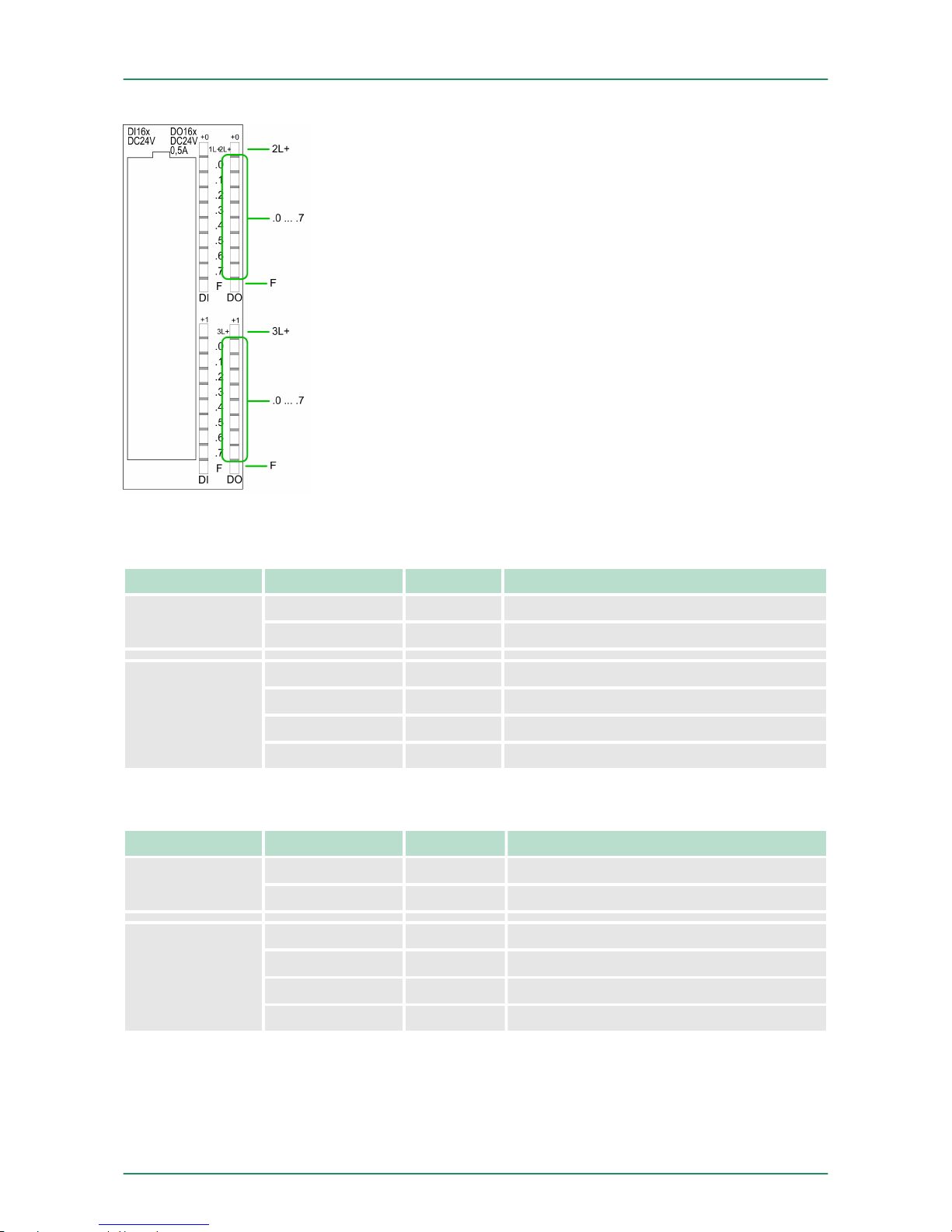
Status indication X11: DO
n 2L+, 3L+
–
LED (green)
Supply voltage available for DO
n .0 ... .7
– LEDs (green)
Q+0.0 ... Q+0.7
Q+1.0 ... Q+1.7
The according LED is on at active output
n F
– LED (red)
Overload or short circuit error
6.3 Address assignment
Sub module Default address Access Assignment
DI16/DO16 124 Byte Digital Input I+0.0 ... I+0.7
125 Byte Digital Input I+1.0 ... I+1.7
Counter 768 DInt Channel 0: Count value / Frequency value
772 DInt Channel 1: Count value / Frequency value
776 DInt Channel 2: Count value / Frequency value
780 DInt reserved
Sub module Default address Access Assignment
DI16/DO16 124 Byte Digital Output Q+0.0 ... Q+0.7
125 Byte Digital Output Q+1.0 ... Q+1.7
Counter 768 DWort reserved
772 DWort reserved
776 DWort reserved
780 DWort reserved
Input range
Output range
VIPA System 300SDeployment I/O periphery
Address assignment
HB140 | CPU-SC | 313-6CF13 | GB | 15-50 100
 Loading...