

Page 1
Technical Documents
r
e
c
Technical
Documents
Interbus
Diagnostics Device
342-0IA00
Order-No.: VIPA HB144E_I BS-DIAG
Reference: RE_342-0IA00
General Information
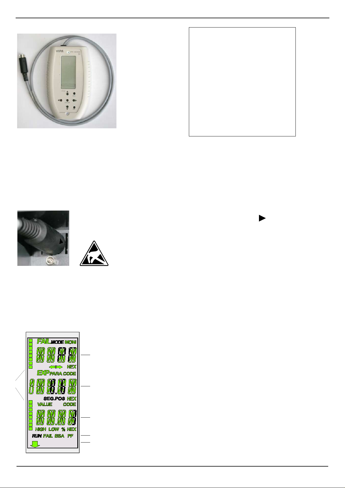
The diagnostics device VIPA 342-0IA00 serves for connection to an Interbus (IBS) m aster module from VIPA with MiniDIN diagnostics jack. By means of the diagnostics device operation and f ault conditions may be represented, recognized
and localized. For this the device has a multi-line LCD dis play for display and a key field for menu-assisted s ervice. The
hardware platform of the diagnostics device (USC/4-DIAG-L) comes from Phoenix Contact as like the IBS hardware
platform of the master (USC4-2). In the following the single components are described only briefly. In the "Diagnostics
guide" of Phoenix Contact a detailed description of the diagnostics possibilities may be found.
Connect the diagnostics device
The diagnostics device is directly supplied by the Mini-DIN jack of the IBS m aster and is ready fo
operation after connection. Please consider that the arrow on the plug shows to the right side
when the diagnostics device is connected to the Mini-DIN jack.
Attention!
Please consider the sufficient grounding when connecting the diagnostics device.
Hardware-caused there is the risk to com e in contact to a pin of the plug while th
diagnostics device is connected. T his could dam age the device by an electrostati
discharge.
LCD-Display
The diagnostics display consists of the following components:
• 3 main lines to display operating states, addresses and data.
• 16 status segments on the left side of the display for binary representation of input and output data.
• CPU STOP status indicator (Arrow is displayed).
• Red (error) or green (normal operation) background illumination, depending on the operating state of the bus.
0
.
.
.
.
.
.
7
1
[1] FAIL
6
2
0
.
.
.
.
.
.
7
3
4
MODE
MONI
HEX
5
STOP
Indicates that an error has occurred and provides information
about the error type.
CTRL Controller error
RBUS Remote bus error
LBUS Local bus error
BUS General bus error
OUT1 Error at the outgoing interface
OUT2 Error at the branching interface
DEV Device error
PF Peripheral fault
When MODE active, further menu items may be selected.
Indicates that monitor mode is activated.
The value in the 1. main line is displayed in hexadecimal notation.
If the HEX segment is not activated, the value is displayed in
decimal notation.
Rev. 09/22
VIPA GmbH · Ohmstr. 4 · D-91074-Herzogenaurach · Ph.:+49-9132-744-0 · Fax:+49-9132-744-1864 · www.vipa.de
Page 2
Interbus Diagnostics Device
[2] PARA
CODE
SEG.POS
HEX
The displayed value is a parameter of a message.
The displayed value represents a code.
The displayed value is a device number (bus segment and position).
The value in the 2. main line is displayed in hexadecimal notation. If the HEX segment
is not activated, the value is displayed in decimal notation.
[3] VALUE
CODE
HIGH
LOW
%
HEX
The displayed number is a value.
The displayed value represents a code.
The displayed number is a high-order word of a 32-bit value.
The displayed number is a low-order word of a 32-bit value.
The displayed number is a percentage term.
The value in the 3. main line is displayed in hexadecimal notation. If the HEX segment
is not activated, the value is displayed in decimal notation.
[4] RUN
Indicates the current operating state of the IBS master:
Off: Interbus at state READY or BOOT
Flashes: Interbus at state ACTIVE
On: Interbus at state RUN
FAIL
Active in the event of controller, user or bus errors.
BSA (Bus Segment Aborted)
Active when a bus segment is switched off and inactive when all segments are
switched on again.
PF (Peripheral Fault)
Active when a device indicates a peripheral fault.
[5] CPU-STOP status
If the superimposed CPU is in STOP state, an arrow appears in the bottom line of the
display pointing to the "STOP" label of the front panel.
[6] Status segments
The 16 status segments for the binary representation of in and output words, are
indicated, if an appropriate menu were opened.
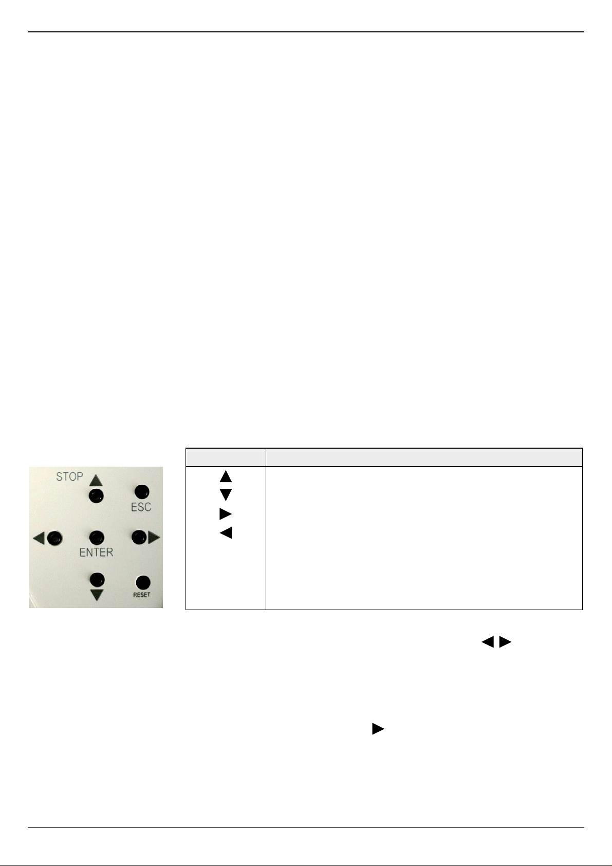
Keypad
The keypad enables menu-driven operation of the diagnostics display using the arrow keys.
Key Description
Go up
Go down
Selection of a menu item or address
Selection of a menu item or address
ENTER Confirm selection
ESC Exit menu item or switch to the next level up
RESET This button is reserved for internal functions and is deactivated at
diagnostics operation.
Selecting a menu item
Different menu items may be selected on the display. You may move within a menu level using the . To jump to the
next level down, confirm the selected menu item by pressing ENTER.
The currently selected menu item is always shown in the 1. line. If there is another level under this menu item, the name of
one of the available menu items will flash in the 2. line. Press ESC to return to the previous level.
Menu structure
To access the MODE and MONI menu items from the standard view, press .
MODE Here you may get information about the current bus configuration and status. Statistical data about the state of
the bus system can also be requested e.g., the error frequency of specific devices.
Further general information such as the firmware version or the serial number are centralized
MONI Via the MONI item the states of inputs and outputs may be displayed. This monitor function is adapted to the
addressing syntax of the CPU.
 Loading...