

Vip2 VK2-VGABX User Manual
VK2-VGABX
User Manual

2

3
WARNING
RISK OF ELECTRIC SHOCK
DO NOT OPEN
WARNING : TO REDUCE THE RISK OF ELECTRIC SHOCK,
DO NOT REMOVE COVER (OR BACK).
NO USER-SERVICEABLE PARTS INSIDE.
REFER SERVICING TO QUALIFIED SERVICE PERSONNEL.
The lightning flash with arrowhead symbol, within an equilateral triangle, is intended to alert the user
to the presence of uninsulated "dangerous voltage" within the product’s enclosure that may be of
sufficient magnitude to constitute a risk of electric shock.
The exclamation point within an equilateral triangle is intended to alert the user to the presence of
important operating and maintenance (servicing) instructions in the literature accompanying the
appliance.
CE COMPLIANCE STATEMENT
WARNING
This is a Class A product. In a domestic environment this product may cause radio
interference in which case the user may be required to take adequate measures.
The information in this manual is believed to be accurate as of the date of publication. The seller is not responsible for any
problems resulting from the use thereof. The information contained herein is subject to change without notice. Revisions or
new editions to this publication may be issued to incorporate such changes.

4
Important Safeguard
1. Read Instructions
All the safety and operating instructions should be read before
the appliance is operated.
2. Retain Instructions
The safety and operating instructions should be retained for
future reference.
3. Cleaning
Unplug this equipment from the wall outlet before cleaning it.
Do not use liquid aerosol cleaners. Use a damp soft cloth for
cleaning.
4. Attachments
Never add any attachments and/or equipment without the
approval of the manufacturer as such additions may result in
the risk of fire, electric shock or other personal injury.
5. Water and/or Moisture
Do not use this equipment near water or in contact with water.
6. Accessories
Do not place this equipment on an unstable cart, stand or table.
The equipment may fall, causing serious injury to a child or
adult, and serious damage to the equipment. Wall or shelf
mounting should follow the manufacturer's instructions, and
should use a mounting kit approved by the manufacturer.
This equipment and cart combination should be moved with
care. Quick stops, excessive force, and uneven surfaces may
cause the equipment and cart combination to overturn.
7. Power Sources
This equipment should be operated only from the type of power
source indicated on the marking label. If you are not sure of
the type of power, please consult your equipment dealer or
local power company.
8. Power Cords
Operator or installer must remove power and TNT connections
before handling the equipment.
9. Lightning
For added protection for this equipment during a lightning
storm, or when it is left unattended and unused for long periods
of time, unplug it from the wall outlet and disconnect the
antenna or cable system. This will prevent damage to the
equipment due to lightning and power-line surges.
10. Overloading
Do not overload wall outlets and extension cords as this can
result in the risk of fire or electric shock.
1. Objects and Liquids
Never push objects of any kind through openings of this
equipment as they may touch dangerous voltage points or
short out parts that could result in a fire or electric shock.
Never spill liquid of any kind on the equipment.
12. Servicing
Do not attempt to service this equipment yourself. Refer all
servicing to qualified service personnel.
13. Damage requiring Service
Unplug this equipment from the wall outlet and refer servicing
to qualified service personnel under the following conditions:
A. When the power-supply cord or the plug has been damaged.
B. If liquid is spilled, or objects have fallen into the equipment.
C. If the equipment has been exposed to rain or water.
D. If the equipment does not operate normally by following the
operating instructions, adjust only those controls that are
covered by the operating instructions as an improper
adjustment of other controls may result in damage and will
often require extensive work by a qualified technician to
restore the equipment to its normal operation.
E. If the equipment has been dropped, or the cabinet damaged.
F. When the equipment exhibits a distinct change in
performance — this indicates a need for service.
14. Replacement Parts
When replacement parts are required, be sure the service
technician has used replacement parts specified by the
manufacturer or that have the same characteristics as the
original part. Unauthorized substitutions may result in fire,
electric shock or other hazards.
15. Safety Check
Upon completion of any service or repairs to this equipment,
ask the service technician to perform safety checks to
determine that the equipment is in proper operating condition.
16. Field Installation
This installation should be made by a qualified service person
and should conform to all local codes.
17. Correct Batteries
Warning: Risk of explosion if battery is replaced by an incorrect
type. Dispose of used batteries according to the instructions.
18. Tmra
A manufacturer’s maximum recommended ambient
temperature (Tmra) for the equipment must be specified so that
the customer and installer may determine a suitable maximum
operating environment for the equipment.
19. Elevated Operating Ambient Temperature
If installed in a closed or multi-unit rack assembly, the operating
ambient temperature of the rack environment may be greater
than room ambient. Therefore, consideration should be given
to installing the equipment in an environment compatible with
the manufacturer’s maximum rated ambient temperature
(Tmra).
20. Reduced Air Flow
Installation of the equipment in the rack should be such that the
amount of airflow required for safe operation of the equipment
is not compromised.
21. Mechanical Loading
Mounting of the equipment in the rack should be such that a
hazardous condition is not caused by uneven mechanical
loading.
22. Circuit Overloading
Consideration should be given to connection of the equipment
to supply circuit and the effect that overloading of circuits might
have on over current protection and supply wiring.
Appropriate consideration of equipment nameplate ratings
should be used when addressing this concern.
23. Reliable Earthing (Grounding)
Reliable grounding of rack mounted equipment should be
maintained. Particular attention should be given to supply
connections other than direct connections to the branch circuit
(e.g., use of power strips).

5
Contents
Contents ........................................................................................................................................................ 5
1. Description .............................................................................................................................................. 6
1.1 Components ................................................................................................................................................ 6
1.2 Key Features ............................................................................................................................................... 7
2. Installation .............................................................................................................................................. 8
2.1 Over View .................................................................................................................................................... 8
2.2 Connection .................................................................................................................................................. 9
2.3 Network Connection and IP assignment ............................................................................................... 10
3. Operation ............................................................................................................................................... 11
3.1 Access from a browser ............................................................................................................................ 11
3.2. Access from the internet ........................................................................................................................ 12
3.3 Setting the admin password over a secure connection ...................................................................... 12
3.4 Live View Page ......................................................................................................................................... 13
3.5 Camera setup menu ................................................................................................................................ 15
3.5.1 Basic Configuration .......................................................................................................................... 16
3.5.2 Video & Image .................................................................................................................................. 21
3.5.3 Event .................................................................................................................................................. 26
3.5.4 System ................................................................................................................................................ 37
3.6 Playback from SD Card .................................................................................................................... 54
3.7 Help ....................................................................................................................................................... 56
3.8 Resetting to the factory default settings ................................................................................... 57
4. Appendix ................................................................................................................................................ 58
4.1 Troubleshooting ....................................................................................................................................... 58
4.2 Preventive Maintenance .......................................................................................................................... 59
4.3 Product Specification ............................................................................................................................... 60
System Requirement for Web Browser ........................................................................................................ 61

6
1. Description
This manual applies to the VIP2 Camera – VK2-VGABX .
The VK2-VGABX comes supplied with its own viewing software which allows the user to view, record
and configure the camera. Viewing and configuration can also be carried out via a web browser such
as Internet Explorer.
The camera can transmit real time full frame rate video in H.264, MJPEG or MPEG4 compression
formats
The alarm input and alarm output can be used to connect various third party devices, such as, door
sensors and alarm bells.
The built in SD card allows local recording of events.
1.1 Components
The system comes with the following components:
VK2-VGABX unit Installation CD Installation Guide
Note: Check your package to make sure that you received the complete system, including all
components shown above.

7
1.2 Key Features
• Excellent video quality
The VK2-VGABX offers the highly efficient H.264 video compression, which drastically reduces
bandwidth and storage requirements without compromising image quality. Motion JPEG is also
supported for increased flexibility.
• Dual streams
The VK2-VGABX can deliver dual video streams simultaneously at full frame rate in all resolutions
up to VGA (640 x 480) using Motion JPEG and H.264 (or MPEG-4). This means that several video
streams can be configured with different compression formats, resolutions and frame rates for
different needs.
• Image setting adjustment
The VK2-VGABX also enables users to adjust image settings such as contrast, brightness and
saturation to improve images before encoding takes place.
• Intelligent video capabilities
The VK2-VGABX includes intelligent capabilities such as enhanced video motion detection. The
encoder’s external inputs and outputs can be connected to devices such as sensors and relays,
enabling the system to react to alarms and activate lights or open/close doors.
• Micro-SD Recording support
The VK2-VGABX also supports a micro-SD memory slot for local recording with removable
storage Up to 32Gb card.
• Improved Security
The VK2-VGABX logs all user access, and lists currently connected users. Also, its full frame rate
video can be provided over HTTPS.
• Power over Ethernet
Support for Power over Ethernet (IEEE802.3af) enables the unit, as well as the camera module
that is connected to it, to receive power through the same cable as for data transmission. This
makes for easy installation since no power outlet is needed.
• ONVIF
This is a global interface standard that makes it easier for end users, integrators, consultants,
and manufacturers to take advantage of the possibilities offered by network video technology.
ONVIF enables interoperability between different vendor products, increased flexibility, reduced
cost, and future-proof systems.

8
2. Installation
For the operation of the VK2-VGABX, it is necessary to connect a network cable for data transmission,
power connection from supplied power adapter. Depending on operation methods, it is possible to
connect an alarm cable additionally. For its fixation on different locations, please consult with an
installer.
2.1 Over View
• Front View
NO
Function
1
Focus adjusting fixing screw
2
Auto IRIS lens connector
• Rear View
NO
Function
Description
1
Power Adaptor Terminal
Connects the supplied power adapter or an external
power supply 12V DC, max. 4.0Watt.
3pin Terminal IO
Connects alarm In/Out.
2
Audio Input
Audio Input Stereo Jack
3
Audio Output
Audio Output Stereo Jack
4
Power Indicator
Indicates power input.
5
Status Indicator
Indicates camera status.
6
Network Connector
(PoE)
RJ-45 port compatible with 10/100Mbps, which have a PoE
function.
7
Reset Button
Executes the factory default.
8
Micro SD Card Slot
Card Slot for Micro SD.

9
• LED Indicators
LED
Color
Indication
Network
Green
Steady for connection to a 100 Mbit/s network. Flashes for
network activity.
Amber
Steady for connection to 10 Mbit/s network. Flashes for
network activity.
Unlit
No network connection.
Status
Red
Steady red for failed upgrade or booting.
Power
Green
Steady green for normal operation or booting.
Flashes green during firmware upgrade.
Note: Steady green and red during booting. Flash green and red during factory default.
2.2 Connection
• Connecting to the RJ-45
Connect a standard RJ-45 cable to the network port of the network camera. Generally a
cross-over cable is used for directly connection to PC, while a direct cable is used for connection
to a hub.
• Connecting Alarms
AI(Alarm In) :
You can use external devices to signal the network camera to react on events. Mechanical or
electrical switches can be wired to the AI (Alarm In) and G (Ground) connectors.
G(Ground) :
Connect the ground side of the alarm input and/or alarm output to the G (Ground) connector.
Alarm Out :
The network camera can activate external devices such as buzzers or lights. Connect the device
to the AO (Alarm Out) and G (Ground) connectors.
• Connecting the Power (if PoE is not being used)
Connect the power of DC12V 0.35A for the network camera. Connect the positive(+) pole to the
‘+’ position and the negative(-) pole to the ‘-‘ position.
Use certified / Listed Class 2 power source only.
10
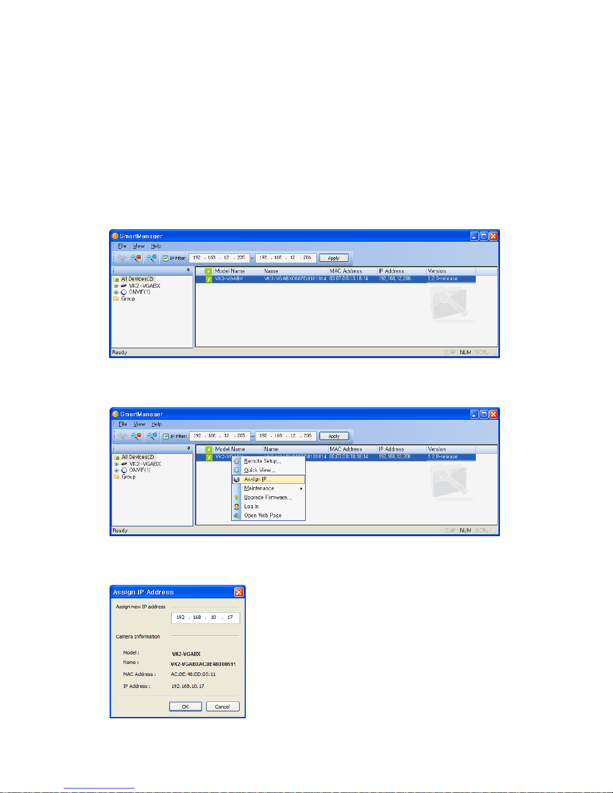
2.3 Network Connection and IP assignment
The VK2-VGABX supports the operation through the network. When a camera is first connected to the
network it has no IP address. So, it is necessary to allocate an IP address to the device with the
“Smart Manager” utility on the CD.
1. Connect the VK2-VGABX / device to the network and power up.
2. Start SmartManager utility ( All programs > VIP2 > SmartManager), the main window will be
displayed, after a short while any network devices connected to the network will be displayed in
the list.
3. Select the camera on the list and click right button of the mouse. You can see the pop-up menu
as below.
. Select “Assign IP” menu. You cam see Assign IP window.
Enter the required IP address.

11
3. Operation
The VK2-VGABX can be used with Windows operating system and browsers. The recommended
browsers are Internet Explorer, Safari, Firefox, Opera and Google Chrome.
Note: To view streaming video in Microsoft Internet Explorer, set your browser to allow ActiveX
controls.
3.1 Access from a browser
1. Start a browser (Internet Explorer).
2. Enter the IP address or host name of the VK2-VGABX in the Location/Address field of your
browser.
3. You can see a starting page. Click Live View, Playback or Setup to enter web page.
4. The encoder’s Live View page appears in your browser.
12
3.2. Access from the internet
Access from the internet once connected, the VK2-VGABX is accessible on your local network (LAN).
To access the video encoder from the Internet you must configure your broadband router to allow
incoming data traffic to the video encoder. To do this, enable the NAT-traversal feature, which will
attempt to automatically configure the router to allow access to the video encoder. This is enabled
from Setup > System > Network > NAT.
For more information, please see NAT traversal (port mapping) for IPv4, on page 54.
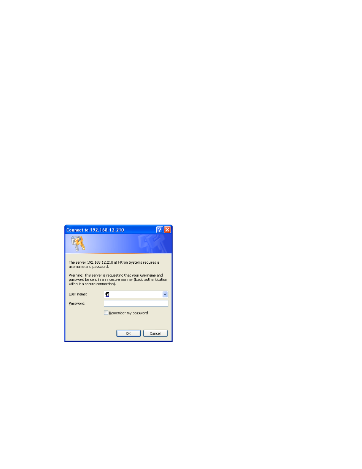
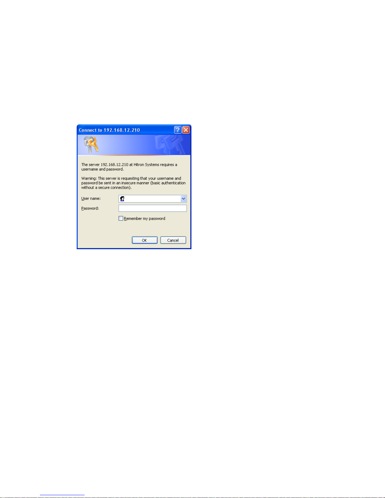
3.3 Setting the admin password over a secure
connection
To gain access to the product, the password for the default administrator user must be set. This is
done in the “Admin Password” dialog, which is displayed when the VK2-VGABX is accessed for the
setup at the first time. Enter your admin name and password, set by the administrator.
Note: The default administrator username and password is “admin”. If the password is lost, the VK2-
VGABX must be reset to the factory default settings. See “3.8 Resetting to the Factory Default
Settings” for more details.
To prevent network eavesdropping when setting the admin password, this can be done via an
encrypted HTTPS connection, which requires an HTTPS certificate (see note below).
To set the password via a standard HTTP connection, enter it directly in the first dialog shown below.
To set the password via an encrypted HTTPS connection, see “3.5.4 System > Security > HTTPS”.
Note: HTTPS (Hypertext Transfer Protocol over SSL) is a protocol used to encrypt the traffic between
web browsers and servers. The HTTPS certificate controls the encrypted exchange of information.
13
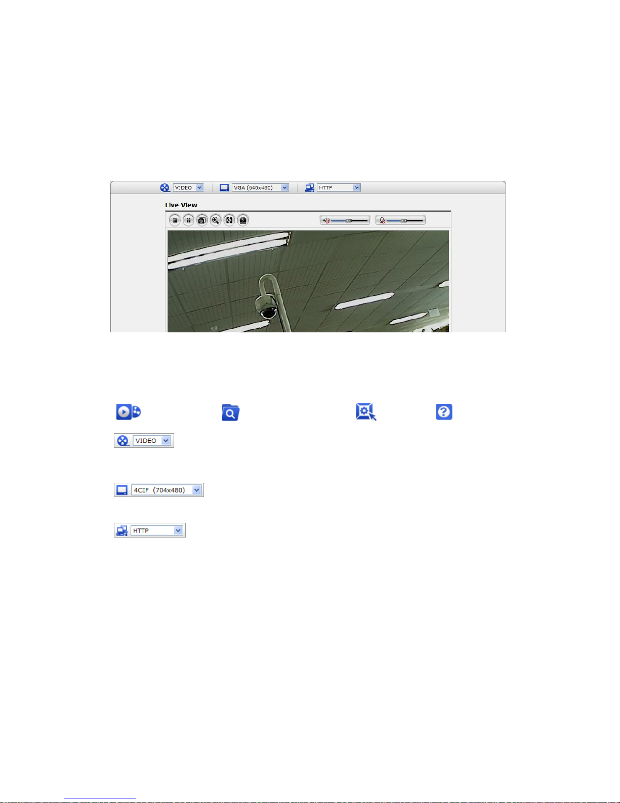
3.4 Live View Page
The live view page comes in eight screen modes like 640x480, 320x240, and 160x120. Users are
allowed to select the most suitable one out of those modes. Please, adjust the mode in accordance
with your PC specifications and monitoring purposes.
1) General controls
Live View Page Search & Playback Page Setup Page Help Page
The video drop-down list allows you to select a customized or pre-programmed
video stream on the live view page. Stream profiles are configured under Setup > Basic
Configuration > Video & Image. See Basic Configuration, on page 26 for more information.
The resolution drop-down list allows you to select the most suitable one
out of video resolutions to be displayed on live view page.
The protocol drop-down list allows you to select which combination of
protocols and methods to use depends on your viewing requirements, and on the properties of
your network.

14
2) Control toolbar
The live viewer toolbar is available in the web browser page only. It displays the following
buttons:
The Stop button stops the video stream being played. Pressing the key again toggles the
start and stop. The Start button connects to the VK2-VGABX or start playing a
video stream.
The Pause button pause the video stream being played.
The Snapshot button takes a snapshot of the current image. The location where the
image is saved can be specified.
The digital zoom activates a zoom-in or zoom-out function for video image on the live
screen.
The Full Screen button causes the video image to fill the entire screen area. No other
windows will be visible. Press the 'Esc' button on the computer keyboard to cancel full
screen view.
The Manual Trigger button activates a pop-up window to manually start or stop the event.
Use this scale to control the volume of the speakers.
Use this scale to control the volume of the microphone.
Use this scale to control the volume of the speakers and microphones.
3) Video Streams
The VK2-VGABX provides several images and video stream formats. Your requirements and the
properties of your network will determine the type you use.
The Live View page in the VK2-VGABX provides access to H.264, MPEG-4 and Motion JPEG video
streams, and to the list of available video streams. Other applications and clients can also access
these video streams/images directly, without going via the Live View page.
15
3.5 Camera setup menu
This section describes how to configure the VK2-VGABX, and is intended for product Administrators,
who have unrestricted access to all the Setup tools; and Operators, who have access to the settings
for Basic, Live View, Video & Image, Audio, Event, and System Configuration.
You can configure the VK2-VGABX by clicking Setup in the top right-hand corner of the Live View page.
Click on this page to access the online help that explains the setup tools.
When accessing the VK2-VGABX for the first
time, the “Admin Password” dialog appears.
Enter your admin name and password, set
by the administrator.
Note: If the password is lost, the VK2VGABX must be reset to the factory default
settings. See “3.8 Resetting to the Factory
Default Settings”.
16
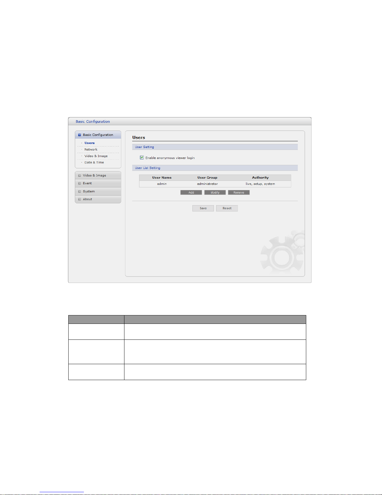
3.5.1 Basic Configuration
1) Users
User access control is enabled by default. An administrator can set up other users, by giving these
user names and passwords. It is also possible to allow anonymous viewer login, which means that
anybody may access the Live View page, as described below:
The user list displays the authorized users and user groups (levels):
User Group
Authority
Guest
Provides the lowest level of access, which only allows access to the
Live View page.
Operator
An operator can view the Live View page, create and modify
events, and adjust certain other settings. Operators have no access
to System Options.
Administrator
An administrator has unrestricted access to the Setup tools and can
determine the registration of all other users.
Enable anonymous viewer login: Check the box to use the webcasting features. Refer to
“3.5.2 Video & Image” for more details.
17
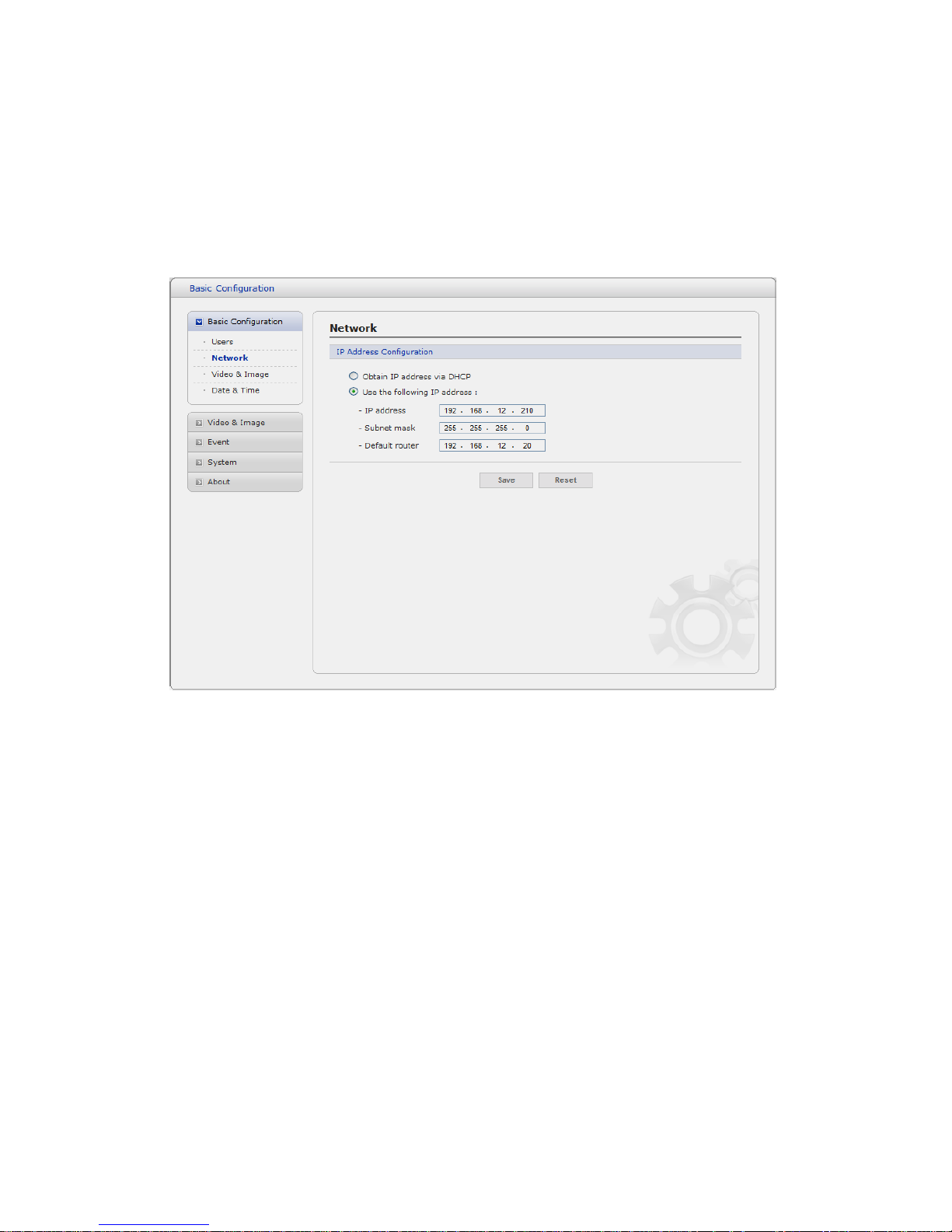
2) Network
The VK2-VGABX supports both IP version 4 and IP version 6. Both versions may be enabled
simultaneously, and at least one version must always be enabled. When using IPv4, the IP address for
the video encoder can be set automatically via DHCP, or a static IP address can be set manually.
If IPv6 is enabled, the video encoders receive an IP address according to the configuration in the
network router. There is also the option of using the Internet Dynamic DNS Service. For more
information on setting the Network, please see Setup> System>Security>Network.
• Obtain IP address via DHCP - Dynamic Host Configuration Protocol (DHCP) is a protocol
that lets network administrators centrally manage and automate the assignment of IP
addresses on a network. DHCP is enabled by default. Although a DHCP server is mostly
used to set an IP address dynamically, it is also possible to use it to set a static, known IP
address for a particular MAC address.
• Use the following IP address - To use a static IP address for the VK2-VGABX,
check the radio button and then make the following settings:
- IP address: Specify a unique IP address for your VK2-VGABX.
- Subnet mask: Specify the mask for the subnet the VK2-VGABX is located on.
- Default router: Specify the IP address of the default router (gateway) used for
connecting devices attached to different networks and network segments.
Notes:
1. DHCP should only be enabled if using dynamic IP address notification, or if your DHCP server can
update a DNS server, which then allows you to access the VK2-VGABX by name (host name). If
DHCP is enabled and you cannot access the unit, you may have to reset it to the factory default
settings and then perform the installation again.
2. The ARP/Ping service is automatically disabled two minutes after the unit is started, or
as soon as an IP address is set.
3. Pinging the unit is still possible when this service is disabled.
18
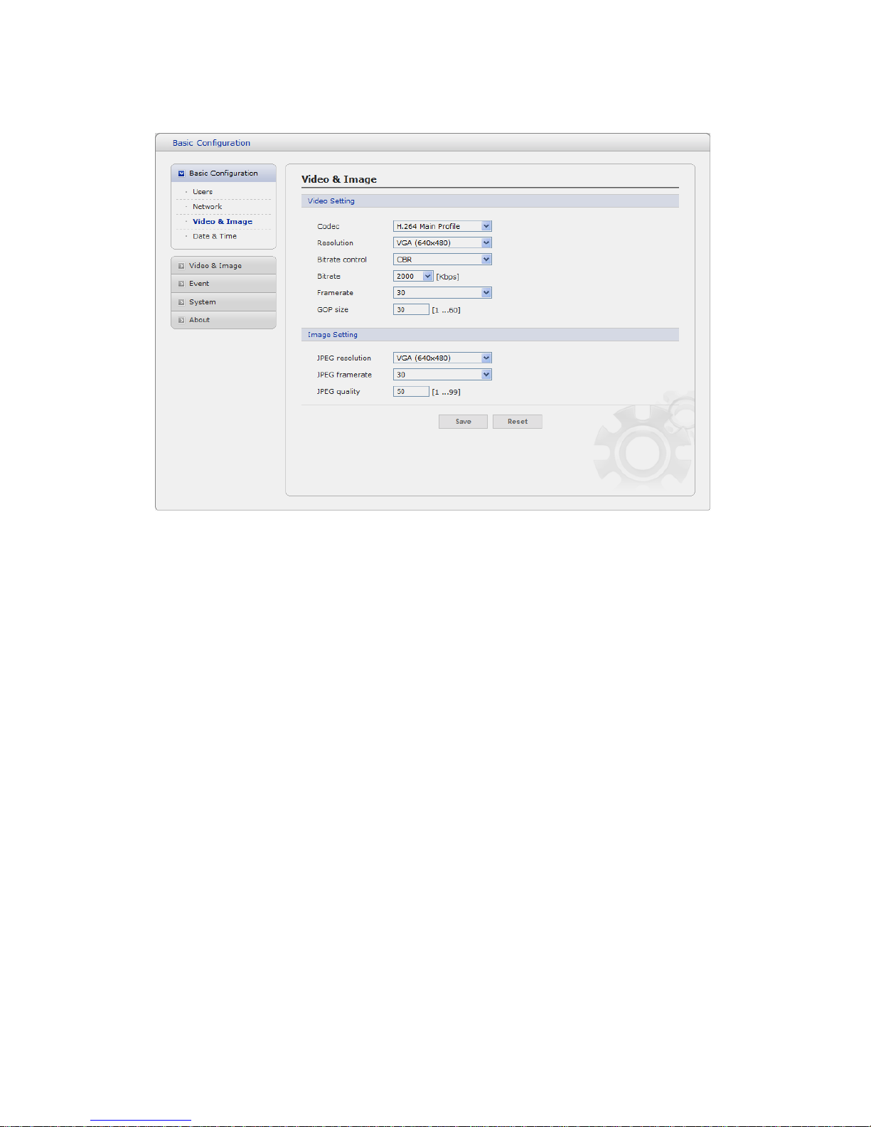
3) Video & Image
• Video Setting
- Codec:
The codec settings are separated into MPEG4 and H.264.
H.264 is also known as MPEG-4 Part 10. This is the new generation compression standard for digital
video. This function offers higher video resolution than Motion JPEG or MPEG-4 at the same bit rate and
bandwidth, or the same quality video at a lower bit rate.
- Profile:
There are 4 pre-programmed stream profiles available for quick set-up.
Choose the form of video encoding you wish to use from the drop-down list:
* H.264 MP(Main Profile):
Primarily for low-cost applications that requires additional error robustness, this profile is
used rarely in videoconferencing and mobile applications, it does add additional error
resilience tools to the Constrained Baseline Profile. The importance of this profile is fading
after the Constrained Baseline Profile has been defined.
* H.264 BP(Base Profile):
Originally intended as the mainstream consumer profile for broadcast and storage
applications, the importance of this profile faded when the High profile was developed for
those applications.
* MPEG4 SP(Simple Profile):
Mostly aimed for use in situations where low bit rate and low resolution are mandated by
other conditions of the applications, like network bandwidth, device size etc.

19
* MPEG4 ASP(Advanced Simple Profile):
Its notable technical features relative to the Simple Profile, which is roughly similar to H.263,
including "MPEG"-style quantization, interlaced video, B pictures (also known as B Frames),
Quarter Pixel motion compensation (Qpel), Global motion compensation (GMC).
- Resolution:
It enables users to determine a basic screen size when having an access through the Web
Browser or PC program. The screen size control comes in seven modes like VGA(640x480),
QVGA(320x240), and QQVGA(160x120). Users can reset the selected screen size anytime
while monitoring the screen on a real-time basis.
- Bitrate control:
Limiting the maximum bit rate helps control the bandwidth used by the H.264 or MPEG-4
video stream. Leaving the Maximum bit rate as unlimited maintains consistently good image
quality but increases bandwidth usage when there is more activity in the image. Limiting the
bit rate to a defined value prevents excessive bandwidth usage, but images are lost when
the limit is exceeded.
Note that the maximum bit rate can be used for both variable and constant bit rates.
The bit rate can be set as Variable Bit Rate (VBR) or Constant Bit Rate (CBR). VBR adjusts
the bit rate according to the image complexity, using up bandwidth for increased activity in
the image, and less for lower activity in the monitored area.
CBR allows you to set a fixed target bitrate that consumes a predictable amount of
bandwidth. As the bit rate would usually need to increase for increased image activity, but in
this case cannot, the frame rate and image quality are affected negatively. To partly
compensate for this, it is possible to prioritize either the frame rate or the image quality
whenever the bit rate needs to be increased. Not setting a priority means the frame rate and
image quality are equally affected.
- Compression:
When it is necessary to adjust a smooth transmission status according to network situations,
users can increase the compressibility to carry out the network transmission stably. On the
other hand, when it is necessary to maintain a detailed monitoring screen by enhancing the
image quality, users can do so by decreasing the compressibility. In ease case, please adjust
this function according to the network status and monitoring purposes. The default is
2000(Kbps).
- Frame rate:
Upon the real-time play, users should select a frame refresh rate per second. If the rate is
high, the image will become smooth. On the other hand, if the rate is low, the image will not
be natural but it can reduce a network load.
- GOP size:
Select the GOP(Group of Picture) size. If users want to have a high quality of fast image one
by one, please decrease the value. For the purpose of general monitoring, please do not
change a basic value. Such act may cause a problem to the system performance. For the
details of GOP setting, please contact the service center.
 Loading...