

Vip2 VK2-REC16HD User Manual

VK2-REC16HD
Network Video Recorder
User Manual

WARNING
TO REDUCE THE RISK OF FIRE OR ELECTRIC SHOCK, DO NOT EXPOSE THIS PROCUCT TO
RAIN OR MOISTURE. DO NOT INSERT ANY METALLIC OBJECT THROUGH THE VENTILATION
GRILLS OR OTHER OPENNINGS ON THE EQUIPMENT.
CAUTION
EXPLANATION OF GRAPHICAL SYMBOLS
The lightning flash with arrowhead symbol, within an equilateral triangle, is intended to alert
the user to the presence of uninsulated "dangerous voltage" within the product’s enclosure
that may be of sufficient magnitude to constitute a risk of electric shock.
The exclamation point within an equilateral triangle is intended to alert the user to the
presence of important operating and maintenance (servicing) instructions in the literature
accompanying the appliance.
PRECAUTIONS
Safety -------------------------------------- Installation -------------------------------
Should any liquid or solid object fall into the
cabinet, unplug the unit and have it checked by
the qualified personnel before operating it any
further.
Unplug the unit from the wall outlet if it is not
going to be used for several days or more. To
disconnect the cord, pull it out by the plug. Never
pull the cord itself.
Allow adequate air circulation to prevent internal
heat build-up. Do not place the unit on surfaces
(rugs, blankets, etc.) or near materials(curtains,
draperies) that may block the ventilation holes.
Height and vertical linearity controls located at the
rear panel are for special adjustments by qualified
personnel only.
Do not install the unit in an extremely hot or
humid place or in a place subject to excessive
dust, mechanical vibration.
The unit is not designed to be waterproof.
Exposure to rain or water may damage the unit.
Cleaning ---------------------------------
Clean the unit with a slightly damp soft cloth.
Use a mild household detergent. Never use
strong solvents such as thinner or benzene as
they might damage the finish of the unit.
Retain the original carton and packing materials
for safe transport of this unit in the future.
Document Images ---------------------
Note – Images in this document are for graphical
representation only and may vary slightly to the
physical product.

FCC COMPLIANCE STATEMENT
INFORMATION TO THE USER: THIS EQUIPMENT HAS BEEN TESTED AND FOUND TO
COMPLY WITH THE LIMITS FOR A CLASS A DIGITAL DEVICE, PURSUANT TO PART 15 OF
THE FCC RULES. THESE LIMITS ARE DESIGNED TO PROVIDE REASONABLE PROTECTION
AGAINST HARMFUL INTERFERENCE WHEN THE EQUIPMENT IS OPERATED IN A
COMMERCIAL ENVIRONMENT. THIS EQUIPMENT GENERATES, USES, AND CAN RADIATE
RADIO FREQUENCY ENERGY AND IF NOT INSTALLED AND USED IN ACCORDANCE WITH
THE INSTRUCTION MANUAL, MAY CAUSE HARMFUL INTERFERENCE TO RADIO
COMMUNICATIONS.
CAUTION: CHANGES OR MODIFICATIONS NOT EXPRESSLY APPROVED BY THE PARTY
RESPONSIBLE FOR COMPLIANCE COULD VOID THE USER'S AUTHORITY TO OPERATE THE
EQUIPMENT.
THIS CLASS A DIGITAL APPARATUS COMPLIES WITH CANADIAN ICES-003.
CET APPAREIL NUMÉRIQUE DE LA CLASSE A EST CONFORME À LA NORME NMB-003 DU
CANADA.
CE COMPLIANCE STATEMENT
WARNING: This is a Class A product. In a domestic environment this product may cause radio
interference in which case the user may be required to take adequate measures.
CAUTION:
RISK OF EXPLOSION IF BATTERY IS REPLACED
BY AN INCORRECT TYPE.
DISPOSE OF USED BATTERIES ACCORDING
TO THE INSTRUCTIONS

IMPORTANT SAFETY INSTRUCTIONS
Read these instructions.
Keep these instructions.
Heed all warnings.
Follow all instructions.
Do not use this apparatus near water.
Clean only with dry cloth.
Do not block any ventilation openings. Install in accordance with the manufacturer’s instructions.
Do not install near any heat sources such as radiators, heat registers, stoves, or other apparatus
(including amplifiers) that produce heat.
Do not defeat the safety purpose of the polarized or grounding-type plug. A polarized plug has two
blades with one wider than the other. A grounding type plug has two blades and a third grounding
prong. The wide blade or the third prong are provided for your safety. If the provided plug does not fit
into your outlet, consult an electrician for replacement of the obsolete outlet.
Protect the power cord from being walked on or pinched particularly at plugs, convenience receptacles,
and the point where they exit from the apparatus.
Only use attachments/accessories specified by the manufacturer.
Use only with the cart, stand, tripod, bracket, or table specified by the
manufacturer, or sold with the apparatus. When a cart is used, use caution
when moving the cart/apparatus combination to avoid injury from tip-over.
Unplug this apparatus during lightning storms or when unused for long
periods of time.
Refer all servicing to qualified service personnel. Servicing is required when
the apparatus has been damaged in any way, such as power-supply cord or
plug is damaged, liquid has been moisture, does not operate normally, or
has been dropped.
CAUTION – THESE SERVICING INSTRUCTIONS ARE FOR USE BY QUALIFIED SERVICE
PERSONNEL ONLY. TO REDUCE THE RISK OF ELECTRIC SHOCK DO NOT PERFORM ANY
SERVICING OTHER THAN THAT CONTAINED IN THE OPERATING INSTRUCTIONS UNLESS
YOU QRE QUALIFIED TO DO SO.
Use satisfy clause 2.5 of IEC60950-1/UL60950-1 or Certified/Listed Class 2 power source only.


Contents
1. Description ........................................................................................................ 1
1.1 Components .............................................................................................. 1
1.2 Key Features ............................................................................................. 2
1.3 Overview .................................................................................................... 3
2. Installation ........................................................................................................ 4
2.1 Connection................................................................................................. 4
2.2 Network Connection and IP assignment .................................................... 9
2.3 Connecting to the Web Interface ...............................................................10
3. Configuration .................................................................................................. 17
3.1 NVR Setup ................................................................................................17
3.1.1 Basic Configuration ................................................................................18
3.1.2 Date/Time ..............................................................................................19
3.1.3 Internet ..................................................................................................20
3.1.4 Intranet ..................................................................................................22
3.1.5 Easy Install ............................................................................................23
3.1.6 Camera Registration ................................................................ ..............23
3.1.7 Record Storage ......................................................................................24
3.2 Camera Setup ...........................................................................................26
3.2.1 Easy Install ............................................................................................26
3.2.2 Camera Registration ................................................................ ..............27
4. Operation ........................................................................................................ 60

4.1 Live Monitoring .........................................................................................60
4.2 Record Playback .......................................................................................63
4.3 Archive Playback ......................................................................................71
4.4 Backup Playback ......................................................................................72
5. Appendix ......................................................................................................... 73
5.1 Troubleshooting ........................................................................................73
5.2 Comprehension about Archive and BACKUP function ..............................74
5.3 Alarm Connection .....................................................................................74
5.4 Preventive Maintenance............................................................................75
5.5 Product Specification ................................................................................75
5.6 Text-In Search ..........................................................................................76

User Manual
Page 1 of 77
1. Description
This manual applies to the VK2 Recorder network video recorder (NVR).
The NVR supports up to 16 network cameras. The NVR can record more than 100 hours of high
quality Full HD images onto its maximum capacity of hard disk drives.
The NVR is extremely straightforward to install and setup, as it detects network cameras and defines
the parameters of each through a dedicated configuration wizard. You can start monitoring instantly,
as the images are automatically assigned to a layout menu.
The Network Camera is fully featured for security surveillance and remote monitoring needs. It is
based on an embedded linux and high performance, and makes it available on the network as realtime, full frame rate Motion JPEG and H.264 (or MPEG-4) video streams.
The alarm input and alarm output can be used to connect various third party devices, such as, door
sensors and alarm bells.
1.1 Components
The system comes with the following components:
Network Video Recorder unit
Power Cord
SATA Hard Disk Drive (Size based on Model)
Rack-mount Kit
Installation CD including VK2 Client Software and User Manual
Installation Guide
Note: Check your package to make sure that you received the complete system, including all
components shown above.

User Manual
Page 2 of 76
1.2 Key Features
The NVR provides recording capabilities up to 16 camera inputs. It provides exceptional picture quality
in both live and playback modes, and offers the following features:
Up to 16 network cameras can be connected and recorded.
H.264, MPEG-4 and JPEG multi format.
Quick setup by automatic camera detection and simple setup wizard without the use of PC.
Supports HD network camera input.
Continuous Recording with the overwrite Mode.
Multiple Recording Mode. (Schedule, Pre-Event, Text-In and Event Recording)
Multiple Search Engines. (Date/Time, Calendar, Event, Text-In, Bookmark)
Daylight savings time change function.
Alarm handling with history log and Pre-alarm recording.
Text Input for POS.
Network Time Synchronization.
Self-diagnostics with automatic notification including hard disk drive S.M.A.R.T. protocol
Live or Recorded Video Access via Ethernet.
Built-in web client. (Live, Search & Playback)
User authentication, 3 user levels and User level – Camera partitioning setup for user
management of up to 32 user registrations
Built-in network interface (10Base-T / 100Base-TX / 1000Base-T) for recording and client access.
IP routing function for direct camera setup via client access.
Up to 4 HDDs can be installed (8.89 cm (3.5 inch) Serial ATA HDD)
Four USB 2.0 Ports
Supports Vista VK2 IP Cameras*
* Vista VK2 cameras have been integrated using the ONVIF protocol. Other third party cameras
supporting the ONVIF protocol maybe compatible with the VK2 Recorder, however, Vista are
unable to provide technical assistance regarding support for third party cameras.
User Manual
Page 3 of 76
1.3 Overview
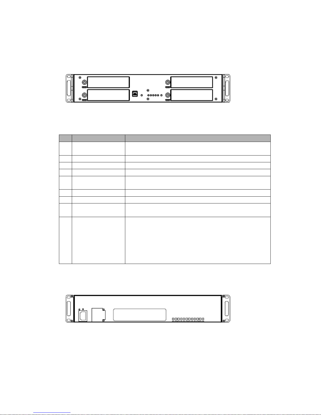
• Front View (2U Rack type)
O
Function
Description
1
USB2.0 Port
Two USB ports are provided to connect external hard disk
drives for data backup or USB-to-Serial text-in device.
2
RS232 Port
Connects to devices such as a text-in device.
3
VGA Port
Not used. Only for maintenance.
4
Client Ethernet Port
A network port that allows the client to connect to the product.
5
Camera Ethernet
Port
A network port that the product connects to the network camera.
6
Power Cord Inlet
Used to connect the product power cable.
7
SMPS Fan
This fan cools the power supply.
8
eSATA Port
The eSATA port is provided to connect external hard disk drives
for expanding storage or archiving video.
9
Alarm I/O Port
Used to connect a sensor or alarm.
1: Alarm Output 2
2: GND
3: Alarm Input 2
4: Alarm Output 1
5: GND
6: Alarm Input 1
• Rear View (2U Rack type)
User Manual
Page 4 of 76
2. Installation
2.1 Connection
• Connecting to the RJ-45
Connect a standard RJ-45 cable to the network port of the network camera. Generally a
cross-over cable is used for directly connection to PC, while a direct cable is used for connection
to a hub.
The 2 network ports on the product back panel are for a computer and camera. The rear panel
network ports can be used for devices within the same network, or in different networks as shown
in the example diagram.
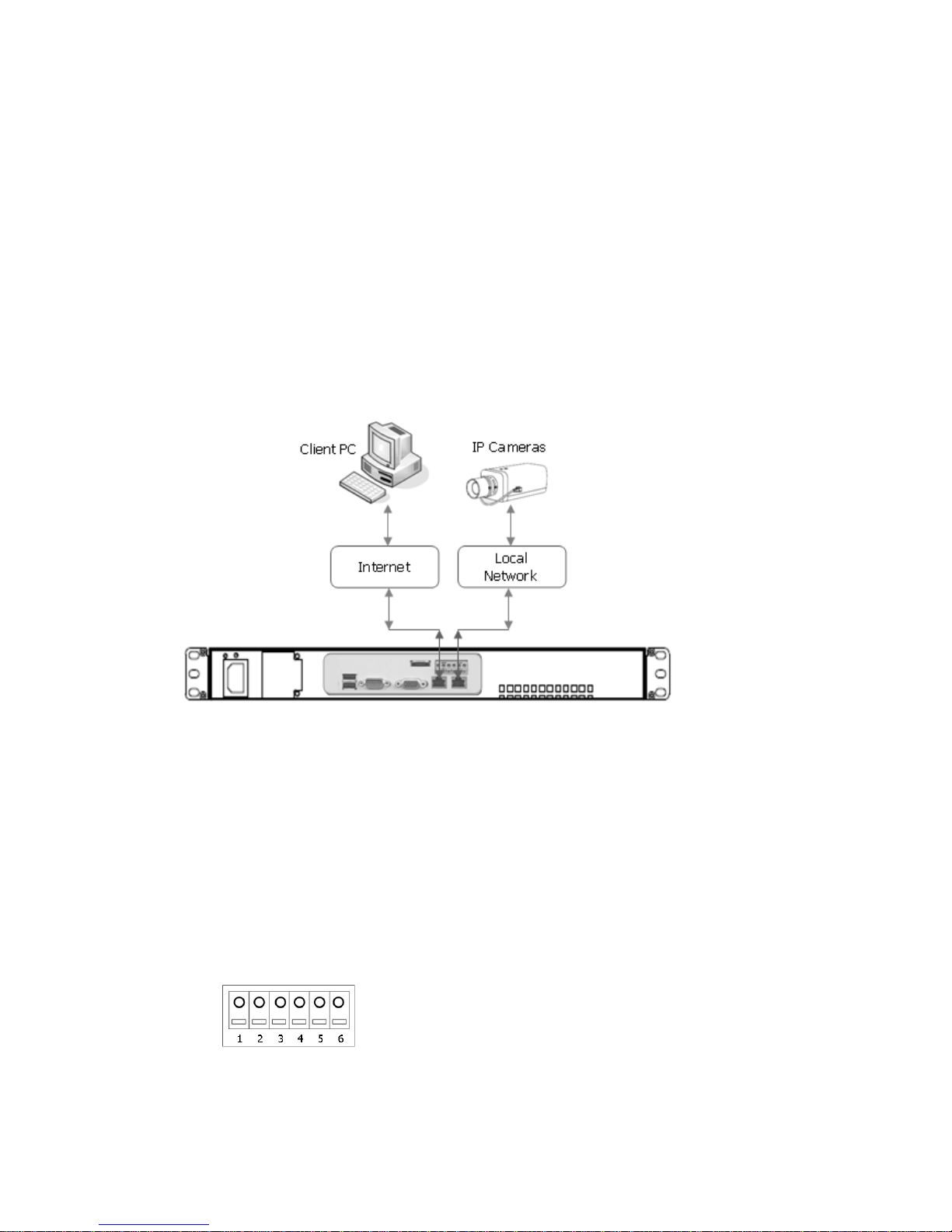
• Connecting Alarms
Alarm Input :
You can use external devices to signal the network camera to react on events. Mechanical or
electrical switches can be wired to the Alarm Input1/2 and GND (Ground) connectors.
GND(Ground) :
Connect the ground side of the alarm input and/or alarm output to the G (Ground) connector.
Alarm Output :
The network camera can activate external devices such as buzzers or lights. Connect the device
to the Alarm Output1/2 and GND(Ground) connectors.

User Manual
Page 5 of 76
• Connecting RS232
An RS232 port is provided to connect a text-in device like a POS. Use a RS232 cable with a DB-9S
(female) connector to connect to the NVR.
RS232
Caution: The VGA port is not used in the NVR.
• Connecting USB
The NVR supports four USB interface for connecting external storage devices; Two USB ports are
located on the rear panel and other two ones are located on the front panel. You can backup some
video clips of internal HDDs to the external HDDs or Memory Stick connected through USB port.
USB2.0
• Connecting eSATA
The NVR supports an eSATA interface for connecting external storage devices; one eSATA port is
located on the rear panel. You can expand storage capacity by utilizing the internal HDDs and eSATA
port.
An external eSATA HDD can be connected to the eSATA port on the rear panel. Note that an eSATA
port does not supply power to the device connected to it; the external device must supply its own
power.
You can also archive video data of internal HDDs to the external HDDs connected through eSATA port.
When the NVR use eSATA port for archiving, it is impossible to expand storage capacity by utilizing
the internal HDDs and eSATA port.
eSATA
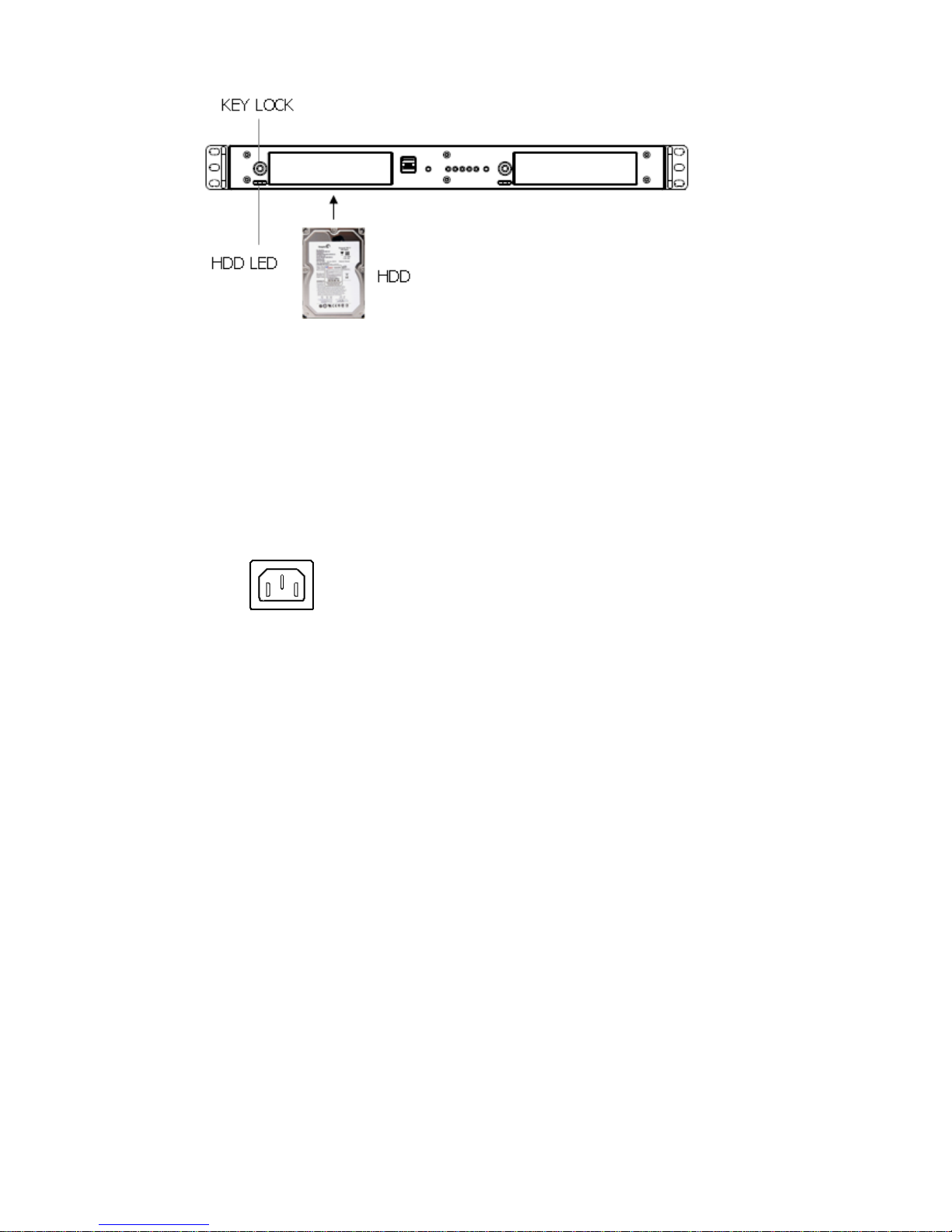
• Inserting SATA HDD
Follow next steps.
1. Turn the Key Lock counterclockwise to unlock
2. Insert the SATA HDD supported to the NVR
3. Turn Key Lock clockwise to lock
User Manual
Page 6 of 76
During the NVR operation, a blue HDD indicator means that internal HDD is installed and
functioning normally.
Caution: For a proper operation, you must insert SATA HDD before turning on the power.
• Connecting the Power Cord
Connect the power cord to the NVR. As the power is supplied, the Power LED will start flickering,
indicating stand-by mode. Pressing the POWER button will turn the power on and the Power LED will
light.
Caution: Power cords must be routed so that they are not likely to be walked on or pinched by
furniture. Do not place the power cords under a carpet. The power plug of this equipment has a
grounding pin. Use only a grounding-type power outlet. Do not destroy the plug even though you are
not able to insert the plug into the outlet. Do not overload wall outlets and extension cords
• Factory Reset
The NVR has a Factory Reset switch to the left of the LED indicators on the front panel. This
switch will only be used on the rare occasions that you want to return all the settings to the
original factory settings.
To reset the unit, you will need to follow steps:
1. Press the Factory Reset button more than 5 seconds while the NVR is operating.
2. While the NVR is initializing, the alarm LED will blink.
3. After initializing, the NVR will restart.
Caution: When using the Factory Reset, you will lose any settings you have saved.

User Manual
Page 7 of 76
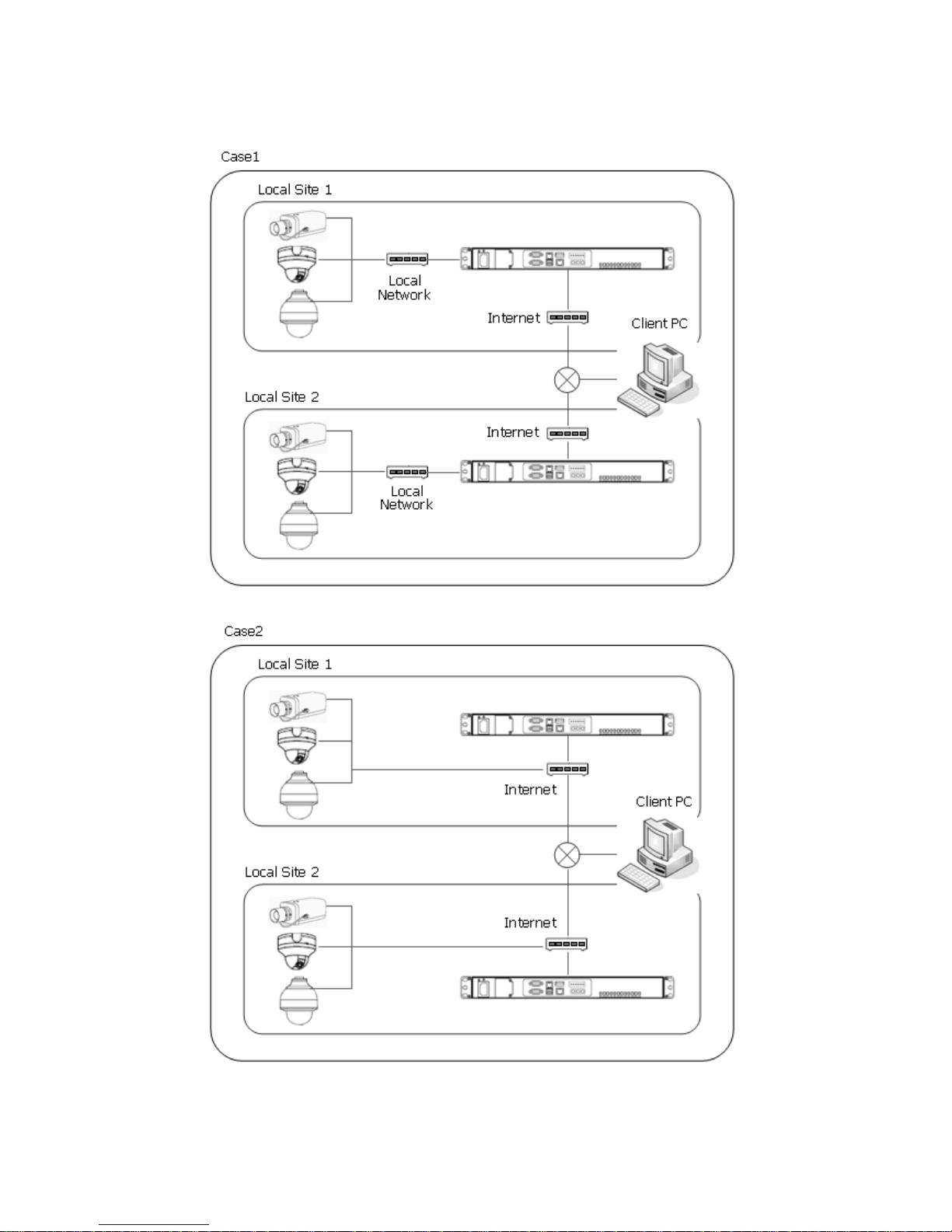
• Configuration
1. Standalone Configuration.
Note: IP cameras can be connected in the local network or in the internet, but Client PC
must be connected in the internet port. For the best network bandwidth, it’s is recommend
that IP cameras and client PC are separated in the network. That is, Case 1 is recommended.
User Manual
Page 8 of 76
2. Multi-location Configuration.
User Manual
Page 9 of 76
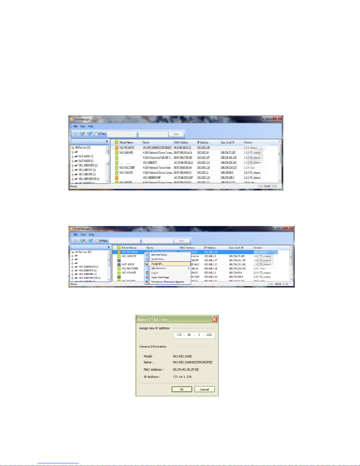
2.2 Network Connection and IP assignment
The Network Video Recorder supports the operation through the network. When the NVR is first
connected to the network it has no IP address. So, it is necessary to allocate an IP address to the
device with the “Smart Manager” utility on the CD.
1. Connect the NVR to the network and power up.
2. Start SmartManager utility ( All programs > SmartManager), the main window will be displayed,
after a short while any network devices connected to the network will be displayed in the list.
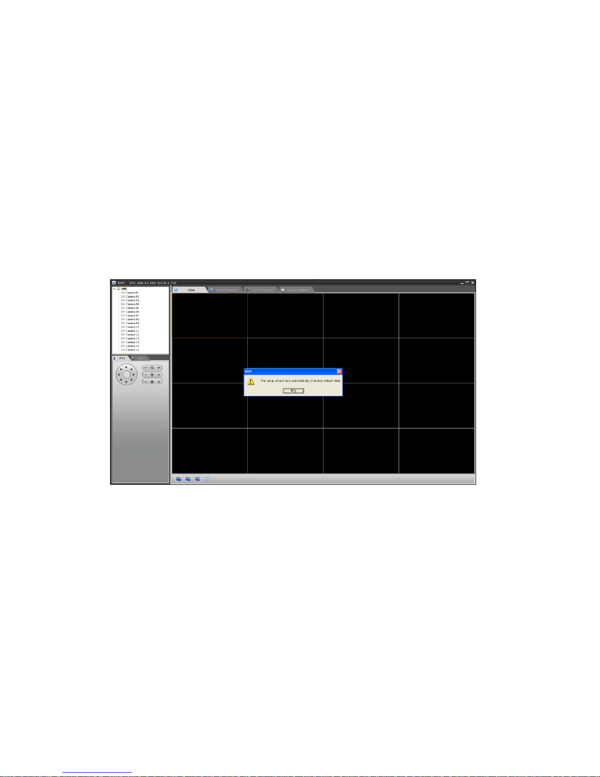
3. Select the NVR on the list and click right button of the mouse. You can see the pop-up menu as
below.
4. Select Assign IP. You can see an assign IP window. Enter the required IP address.
Note: For more information, refer to the Smart Manger User’s Manual.
User Manual
Page 10 of 76
2.3 Connecting to the Web Interface
The Network Video Recorder supports the operation through the network. When the NVR is first
connected to the network, it has no IP address. So, it is necessary to allocate an IP address to the
device with the “Smart Manager” utility on the CD.
Note: Factory Default IP address is 192.168.100.220
1. Start a browser (Internet Explorer).
2. Enter the IP address or host name of the Network Video Recorder in the Location/Address field of
your browser. The VK2 Recorder installs and executes the client software automatically after
installing ActiveX.
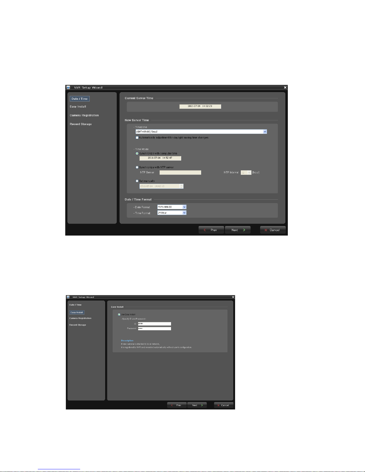
3. If the NVR has not been configured, Setup Wizard will be shown. This drastically reduces the time
required for system installation. Images from cameras are connected and recorded automatically
to the NVR, so that you can start monitoring and recording instantly.
Note: Setup Wizard window will be shown only in factory default state.
Follow the instructions of the wizard to complete the system setup.
User Manual
Page 11 of 76
[Step1]
Enter the date and time settings. You can select to synchronize the server time with an internet
time server. If you enter a domain name for the NTP server, make sure you have set up a correct
DNS server. Click the Next button to go to next page.
[Step2]
Easy Installation means the NVR detects Vista VK2 Cameras based on the network and registers
them automatically. Change the admin password or use the default password (admin) of
cameras to be detected. If you don’t want to use Easy Install function, inactivate checkbox. In
case that you activated Easy Installation, you don’t need to do Step3. Click the Next button to go
to next page.
Note: Easy Install is inactivated in factory default.
User Manual
Page 12 of 76
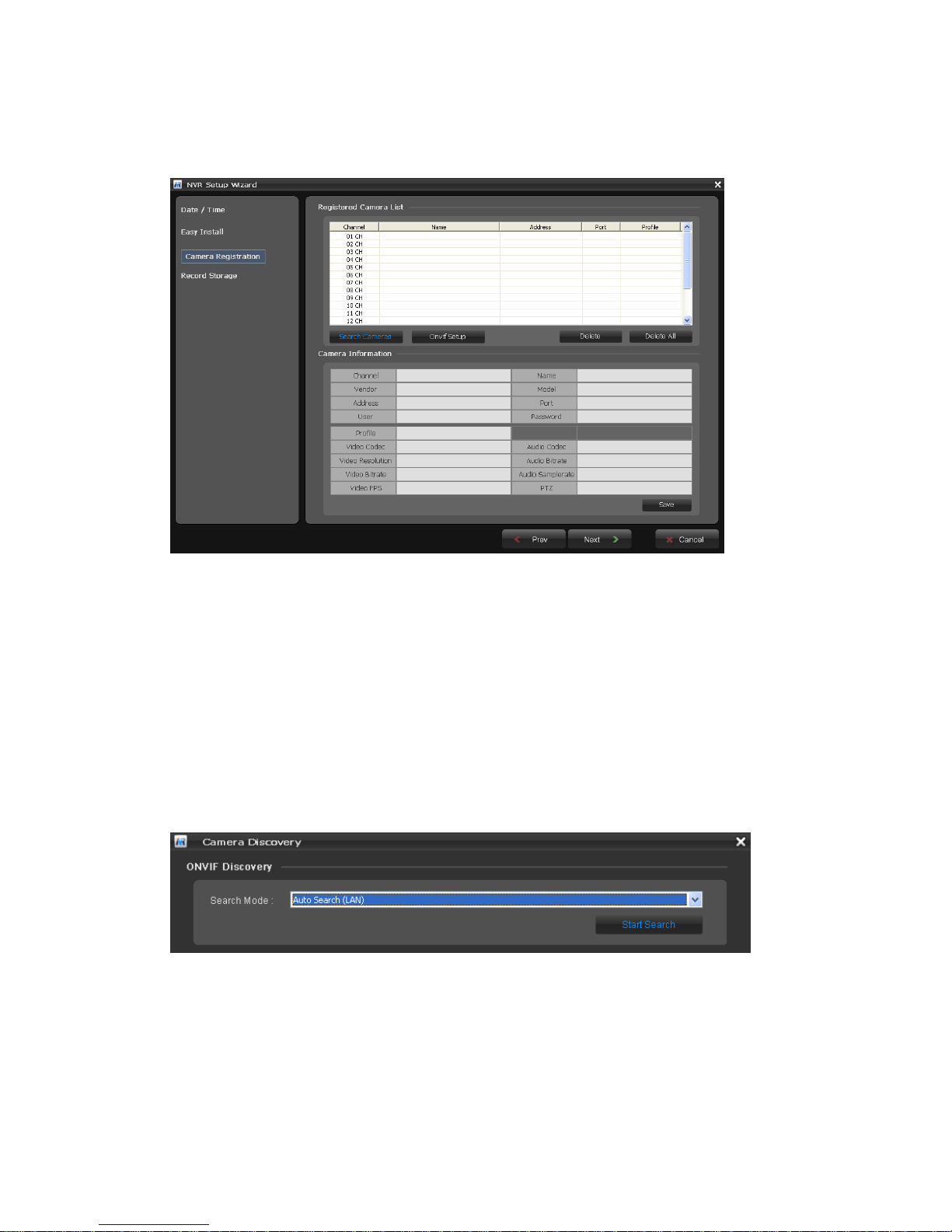
[Step3]
The NVR detects all of IP cameras connected in the intranet and displays in the camera list.
Click the Search Cameras button and the Camera Discovery window appears. Select one of three
in Search Mode and click the Start Search button.
Note: The NVR supports only Vista VK2 Cameras.
• Search Mode:
- Auto Search (LAN): Lists cameras in a LAN environment.
- IP Search (Single): Allows you to enter the IP address of a device. You can search more
than one device at a time by entering a range of IP addresses.
- Domain Name Search: Allows you to enter the domain name registered on a DDNS
server if the camera uses the DDNS function.

User Manual
Page 13 of 76
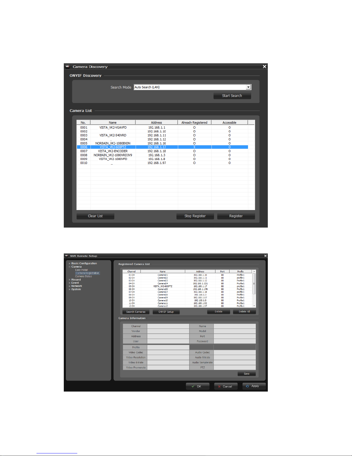
All cameras detected are displayed in the list. Display the name and IP address the selected camera.
The name will be updated automatically depending on the settings of the network camera.
Select one or several cameras from the list and click the Register button to register. The Login
window appears and inquires ID and Password.
[One camera selection] [Several camera selection]
Enter the user ID and password which you set in the camera and click the OK button in order to
connect to that camera remotely. In case of selecting several cameras and registering, the
username and password box will be displayed several times.
User Manual
Page 14 of 76
You can see the result in the Already Registered column of the ONVIF Discovery window whether
succeed in registration or not.
The NVR displays the registered camera list in the Camera Registration window.
User Manual
Page 15 of 76
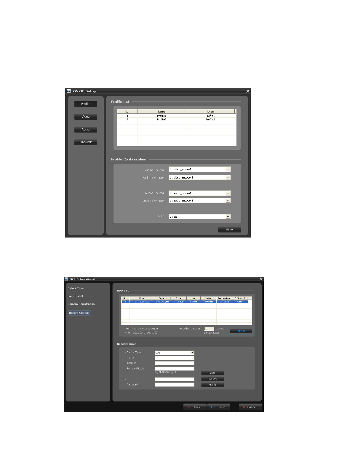
When you select a camera channel in the list, the basic information for that camera is displayed in
Camera Information section. Configure camera settings you want to change. Click the Save button
to save settings changed.
If you want to configure more detail information for a selected camera, click the ONVIF Setup
button in the Setup Wizard window. You can configure camera settings about Profile, Video, Audio,
and Network.
[Step4]
The list of available hard disk drives is displayed with the information of the hard disk drives.
Select a hard disk drive from the list and click the Format button.
Caution: The HDD must be formatted before recordings will start.
User Manual
Page 16 of 76
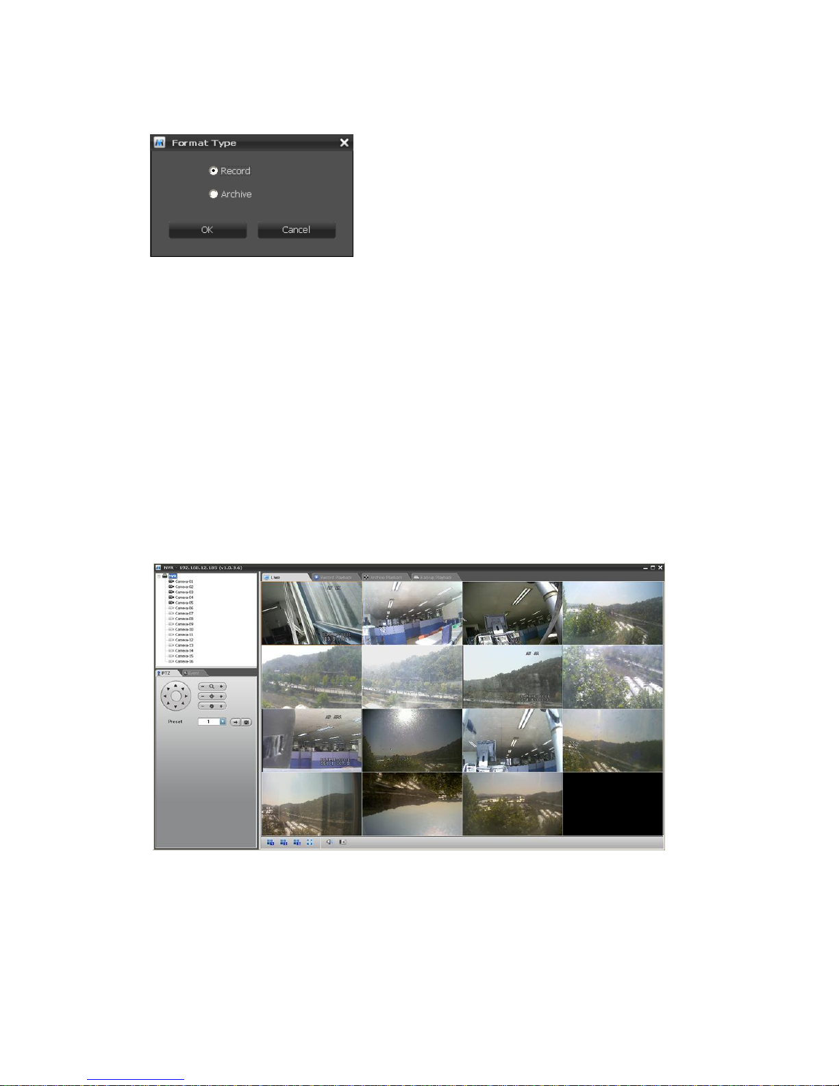
When you click the Format button, the NVR askes you to set the storage to record or archive device. If
the storage is formatted to archiving device, it can be used as a record storage.
Note: Archive records a video to the recording storage
and copies it to the archive storage at the same time.
The external USB HDD can be set to backup device only.
Please refer to “5.2 Comprehension about Archive and BACKUP function” for more information.
The current temperature of the hard disk will be displayed in the Temperature column. The
Temperature column displays Good if the temperature is below the limit and Bad if the temperature is
above the limit.
If the hard disk installed in the NVR supports S.M.A.R.T. (Self-Monitoring Analysis and Reporting
Technology) monitoring program, the status of the installed IDE hard disk is displayed. The current
status of the Disk S.M.A.R.T. will be displayed in the S.M.A.R.T column. The S.M.A.R.T field displays
Good if the Disk S.M.A.R.T. is good and Bad if it is bad.
The Disk Temperature and S.M.A.R.T. status is monitored in real-time.
Click the Finish button to exit Setup Wizard window. If you completed the Setup Wizard step
successfully, the NVR displays a live screen and starts recording automatically.
Note: In case that you don’t use Easy Installation function, you must register and configure IP
cameras manually for proper operation.
User Manual
Page 17 of 76
3. Configuration
3.1 NVR Setup
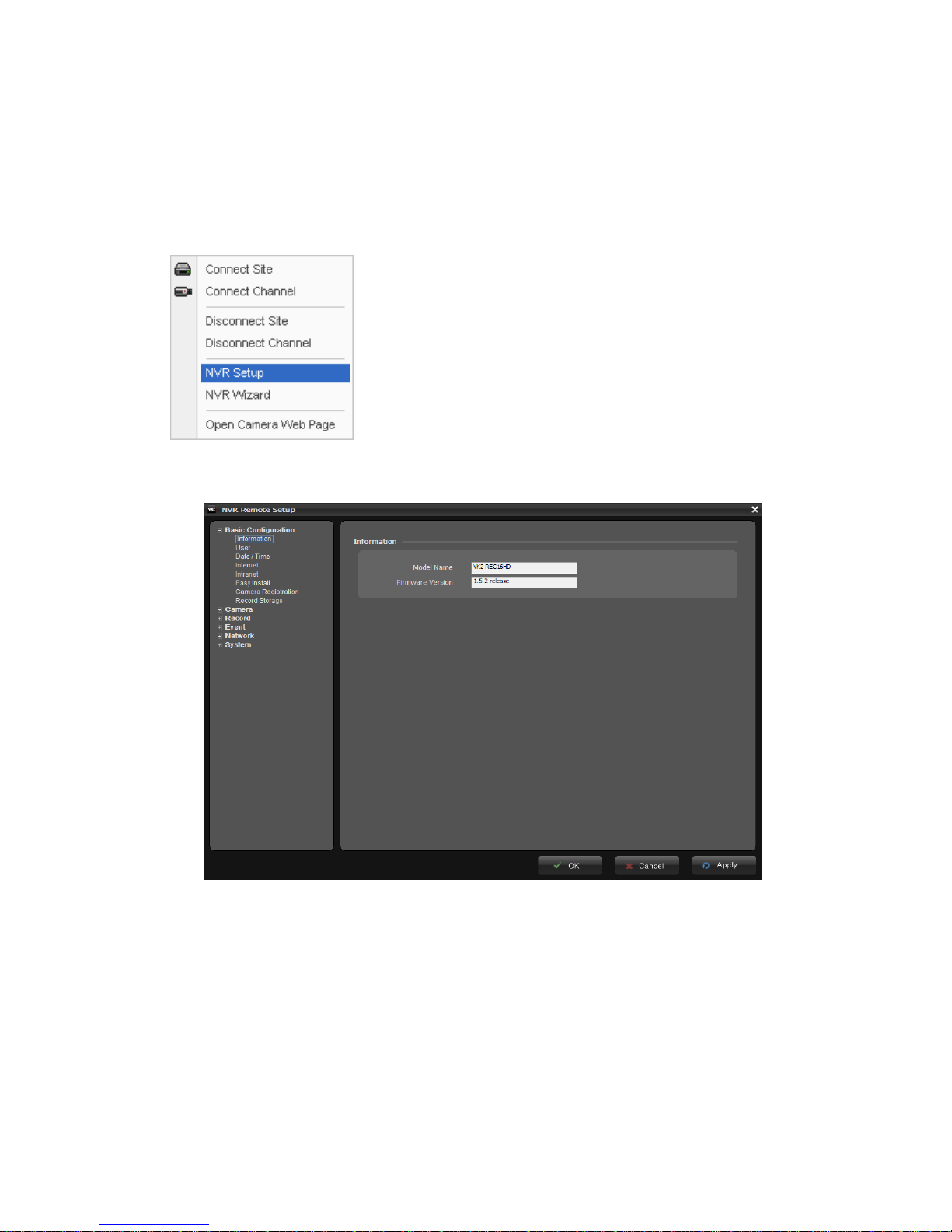
Select “Live” tab on the main window of the Client s/w. You can see the camera list currently registered.
Select NVR or Camera in the list and right-click of mouse. The pop-up menu appears as below.
Select “NVR Setup” and the following screen appear.
User Manual
Page 18 of 76
3.1.1 Basic Configuration
This menu offers basic settings in order to perform proper operation.
1) Information
You can name the Device Name for the NVR. This page is very useful when you refer device
information after installation.
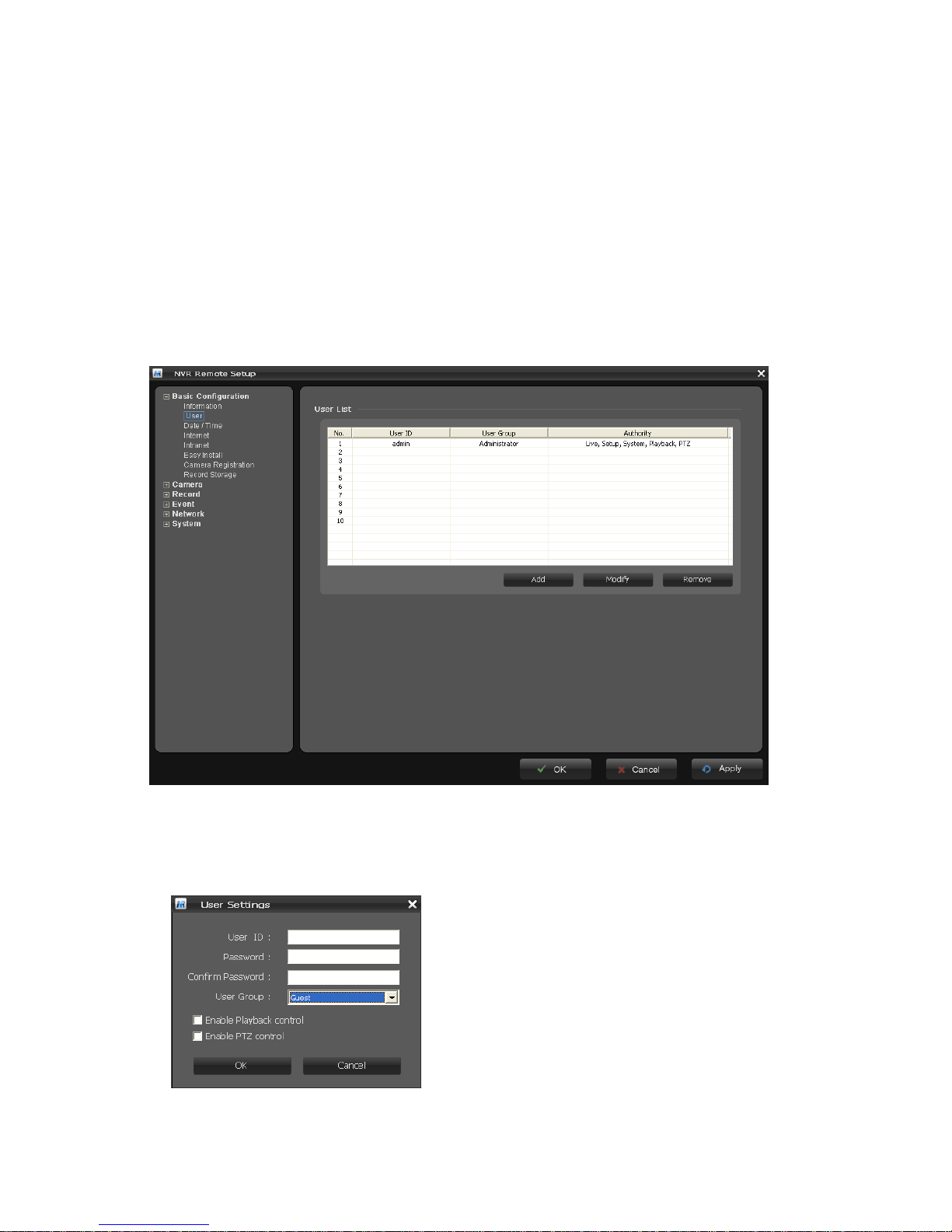
2) User
You can add and delete and users. When adding a user, you can assign authority levels to the users.
User access control is enabled by default. An administrator can set up other users, by giving these
user IDs, passwords and access rights. Click the Add button to add a new user.
 Loading...