

Vip2 VK2-1080VRD3V9, VK2-1080VRDIR3V9F, VK2-1080VRD3V9F Installation And User Manual
VK2-1080VRD(IR)3V9(F)
Installation and user manual

VK2-1080VRD(IR)3V9(F) manual V1.0
2
VK2-1080VRD(IR)3V9(F) manual V1.0
3
Apparatus shall not be exposed to dripping or splashing and that no objects filled with
liquids, such as vases, shall be placed on the apparatus.
CAUTION
EXPLANATION OF GRAPHICAL SYMBOLS
The lightning flash with arrowhead symbol, within an equilateral triangle, is
intended to alert the user to the presence of uninsulated "dangerous
voltage" within the product’s enclosure that may be of sufficient magnitude
to constitute a risk of electric shock.
The exclamation point within an equilateral triangle is intended to alert the
user to the presence of important operating and maintenance (servicing)
instructions in the literature accompanying the appliance.
CAUTION: CHANGES OR MODIFICATIONS NOT EXPRESSLY APPROVED BY THE PARTY
RESPONSIBLE FOR COMPLIANCE COULD VOID THE USER'S AUTHORITY TO OPERATE THE
EQUIPMENT.
CE COMPLIANCE STATEMENT
WARNING: This is a Class A product. In a domestic environment this product may cause radio
interference in which case the user may be required to take adequate measures.

VK2-1080VRD(IR)3V9(F) manual V1.0
4
IMPORTANT SAFETY INSTRUCTIONS
1. Read these instructions.
2. Keep these instructions.
3. Heed all warnings.
4. Follow all instructions.
5. Do not use this apparatus near water.
6. Clean only with dry cloth.
7. Do not block any ventilation openings. Install in accordance with the manufacturer’s
instructions.
8. Do not install near any heat sources such as radiators, heat registers, stoves, or other
apparatus (including amplifiers) that produce heat.
9. Do not defeat the safety purpose of the polarized or grounding-type plug. A polarized plug has
two blades with one wider than the other. A grounding type plug has two blades and a third
grounding prong. The wide blade or the third prong are provided for your safety. If the
provided plug does not fit into your outlet, consult an electrician for replacement of the
obsolete outlet.
10. Protect the power cord from being walked on or pinched particularly at plugs, convenience
receptacles, and the point where they exit from the apparatus.
11. Only use attachments/accessories specified by the manufacturer.
12. Use only with the cart, stand, tripod, bracket, or table specified
by the manufacturer, or sold with the apparatus. When a cart is
used, use caution when moving the cart/apparatus combination
to avoid injury from tip-over.
13. Unplug this apparatus during lightning storms or when unused
for long periods of time.
14. Refer all servicing to qualified service personnel. Servicing is
required when the apparatus has been damaged in any way,
such as power-supply cord or plug is damaged, liquid has been
spilled or objects have fallen into the apparatus, the apparatus has been exposed to rain or
moisture, does not operate normally, or has been dropped.
15. CAUTION – THESE SERVICING INSTRUCTIONS ARE FOR USE BY QUALIFIED
SERVICE PERSONNEL ONLY. TO REDUCE THE RISK OF ELECTRIC SHOCK DO
NOT PERFORM ANY SERVICING OTHER THAN THAT CONTAINED IN THE
OPERATING INSTRUCTIONS UNLESS YOU QRE QUALIFIED TO DO SO.
16. Use satisfy clause 2.5 of IEC60950-1/UL60950-1 or Certified/Listed Class 2
power source only.
17. ITE is to be connected only to PoE networks without routing to the outside plant.

VK2-1080VRD(IR)3V9(F) manual V1.0
5
Contents
1. Description ................................................................................... 7
1.1 Components ............................................................................................. 7
1.2 Key Features ............................................................................................ 8
2. Installation ....................................................................................................... 9
2.1 Over View ................................................................................................. 9
2.2 Connection ..............................................................................................15
2.3 Network Connection and IP assignment ...............................................18
3. Operation ....................................................................................................... 19
3.1 Access from a browser ...........................................................................19
3.2. Access from the internet .......................................................................20
3.3 Setting the admin password over a secure connection .......................20
3.4 Live View Page ........................................................................................21
3.5 Setup ........................................................................................................23
3.5.1 Basic Configuration ............................................................................................. 23
3.5.2 Video & Image ..................................................................................................... 31
3.5.3 Audio.................................................................................................................... 38
3.5.4 Event.................................................................................................................... 39
3.5.5 System ................................................................................................................. 53
3.5.6 About ................................................................................................................... 69
3.6 Playback ..................................................................................................70
3.7 Help ..........................................................................................................72
3.8 Resetting to the factory default settings ...............................................73

VK2-1080VRD(IR)3V9(F) manual V1.0
6
4. Appendix ....................................................................................................... 74
4.1 Troubleshooting ......................................................................................74
4.2 Alarm Connection ...................................................................................75
4.3 Preventive Maintenance .........................................................................75
4.4 Product Specification .............................................................................76
4.5 System Requirement for Web Browser .................................................77
VK2-1080VRD(IR)3V9(F) manual V1.0
7
1. Description
This manual applies to the VK2-1080VRDIR3V9F, VK2-1080VRD3V9F and VK2-1080VRD3V9
These domes are fully featured Vandal resistant day/night IP cameras
Model Name
Features
VK2-1080VRD3V9
Varifocal Lens
No IR LED
VK2-1080VRD3V9F
Motorized Varifocal Lens
No IR LED
VK2-1080VRDIR3V9F
Motorized Varifocal Lens
Built-in 24 IR LEDs
The In built IR LEDs will guarantee 24/7 images at a range of up to 10m.
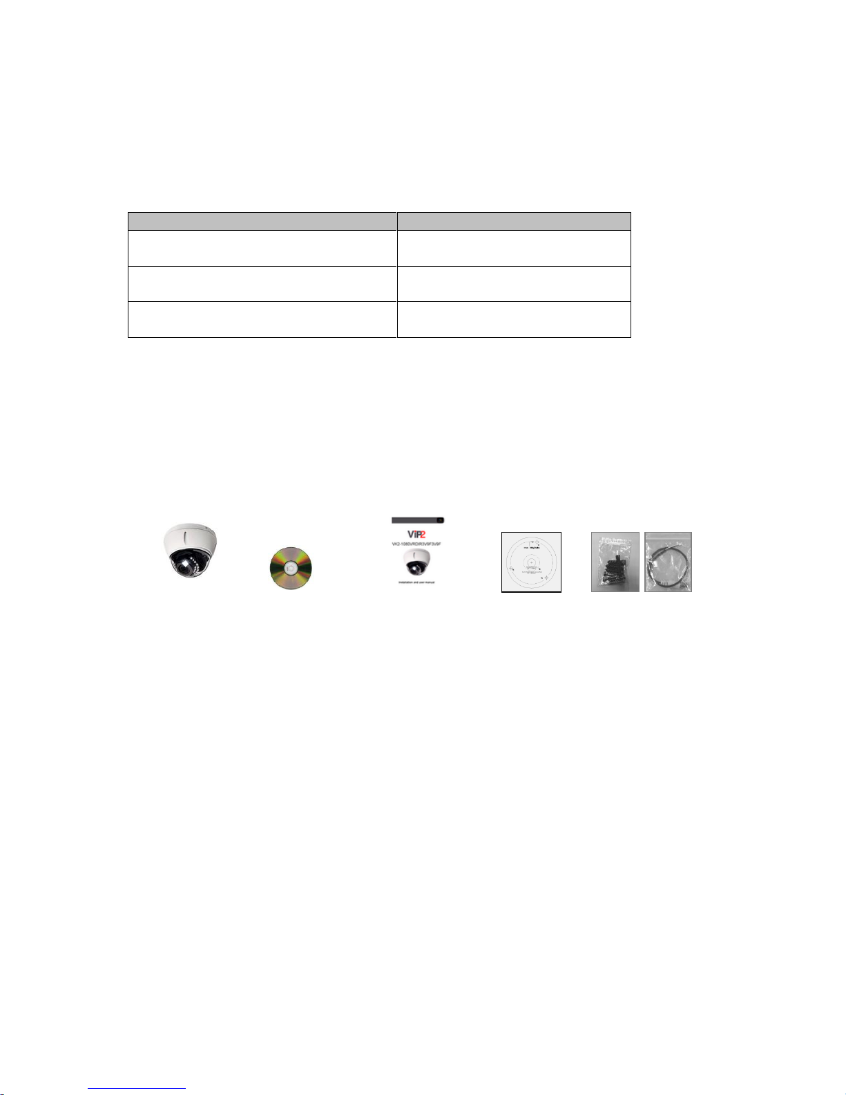
1.1 Camera contents
The camera comes with the following components:
Camera unit Installation CD Installation Guide Template Sheet Accessory Kit
Note: Check your package to make sure that you received the complete system, including all
components shown above.

VK2-1080VRD(IR)3V9(F) manual V1.0
8
1.2 Key Features
• Brilliant video quality
The Network Camera offers the highly efficient H.264 video compression, which drastically
reduces bandwidth and storage requirements without compromising image quality. Motion JPEG
is also supported for increased flexibility.
• Dual or triple streams
The Network Camera can deliver dual or triple video streams simultaneously at full frame rate in
all resolutions up to Full-HD(1920 x 1080p) using Motion JPEG and H.264 (or MPEG-4). This
means that several video streams can be configured with different compression formats,
resolutions and frame rates for different needs.
• Image setting adjustment
The Network Camera also enables users to adjust image settings such as contrast, brightness
and saturation to improve images before encoding takes place.
• Intelligent video capabilities
The Network Camera includes intelligent capabilities such as enhanced video motion detection.
The network camera’s external inputs and outputs can be connected to devices such as sensors
and relays, enabling the system to react to alarms and activate lights or open/close doors.
• Easy Focus (Models equipped with Motorized Lens only)
Easy Focus will be activated once Day/Night mode switched, and the focus readjusted
automatically.
• Focus & Zoom Control via Network (Models equipped with Motorized Lens only)
The Network Camera also enables users to adjust focus and zoom remotely via network.
• Resolution
VK2-1080VRD3V9 / VK2-1080VRD3V9F / VK2-1080VRDIR3V9F, 25fps@1920x1080
• Micro-SD Recording support
The Network Camera also supports a micro-SD memory slot for local recording with removable
storage.
• Improved Security
The Network Camera logs all user access, and lists currently connected users. Also, its full frame
rate video can be provided over HTTPS.
• Power over Ethernet
Support for Power over Ethernet (IEEE802.3af) enables the unit, as well as the camera module
that is connected to it, to receive power through the same cable as for data transmission. This
makes for easy installation since no power outlet is needed.
• ONVIF
This is a global interface standard that makes it easier for end users, integrators, consultants,
and manufacturers to take advantage of the possibilities offered by network video technology.
ONVIF enables interoperability between different vendor products, increased flexibility, reduced
cost, and future-proof systems.
VK2-1080VRD(IR)3V9(F) manual V1.0
9
2. Installation
For the operation of the Network Camera, it is necessary to connect a network cable for data
transmission, power connection from supplied power adapter. Depending on operation methods, it is
possible to connect an alarm cable additionally. For its fixation on different locations, please consult
with an installer.
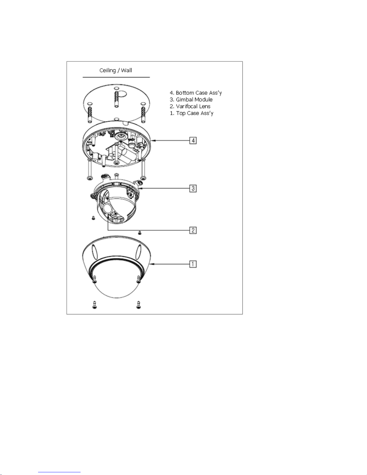
2.1 Over View
Parts and Description(Models equipped with IR LEDs only)
VK2-1080VRD(IR)3V9(F) manual V1.0
10
Parts and Description(Models equipped without IR LEDs only)
VK2-1080VRD(IR)3V9(F) manual V1.0
11
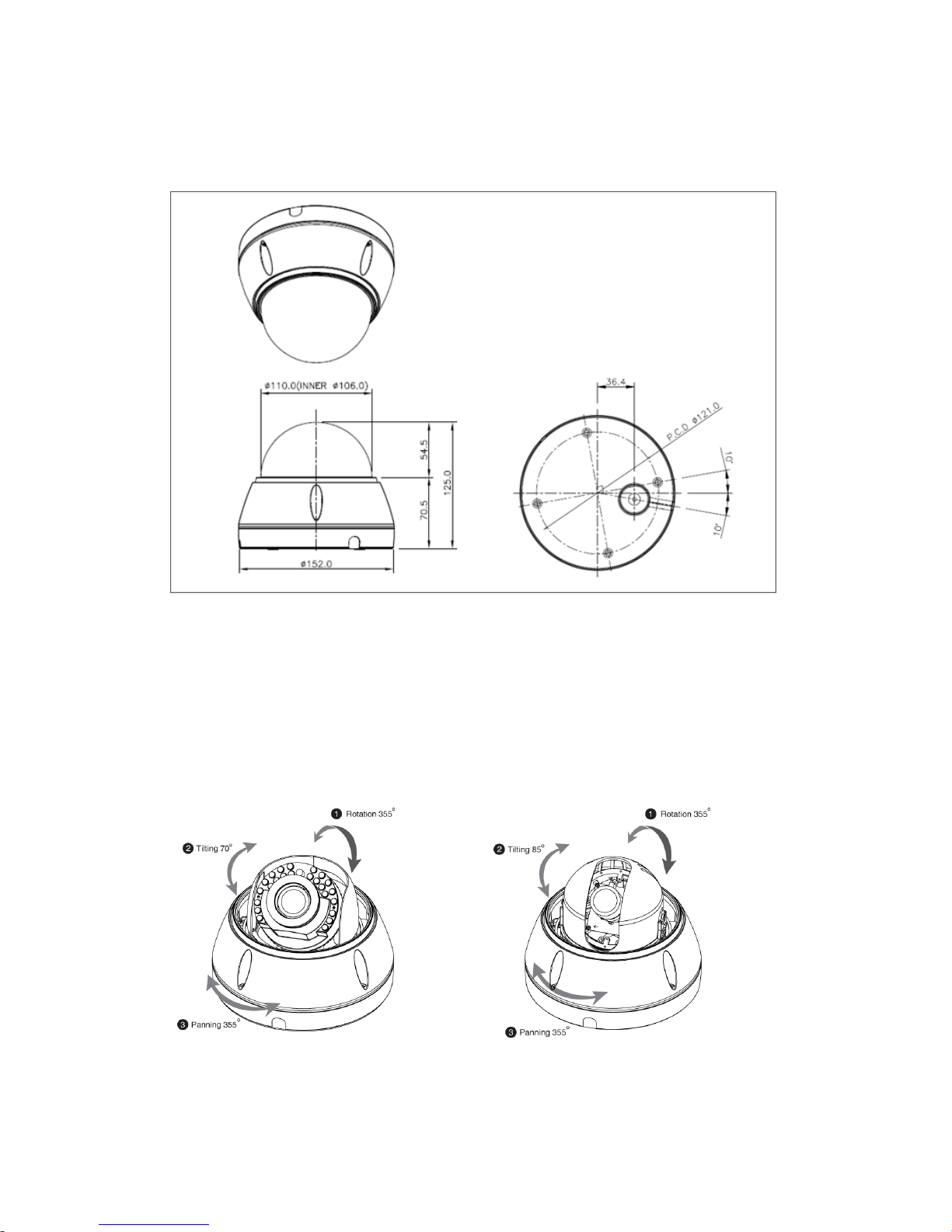
Camera Dimension
See the diagrams below for the exact dimension of the vandal proof dome network cameras.
Dimensions Unit: mm
Adjusting the 3-Axis Gimble
The Gimble mechanism yields maximum rotation and placement as shown below.
• Z-Axis: Rotation 355°
• Y-Axis: Tilting 70°(Models equipped with IR LEDs only), 85°(Models equipped without IR LEDs only)
• X-Axis: Panning 355°
Models equipped with IR LEDs only Models equipped without IR LEDs only
VK2-1080VRD(IR)3V9(F) manual V1.0
12
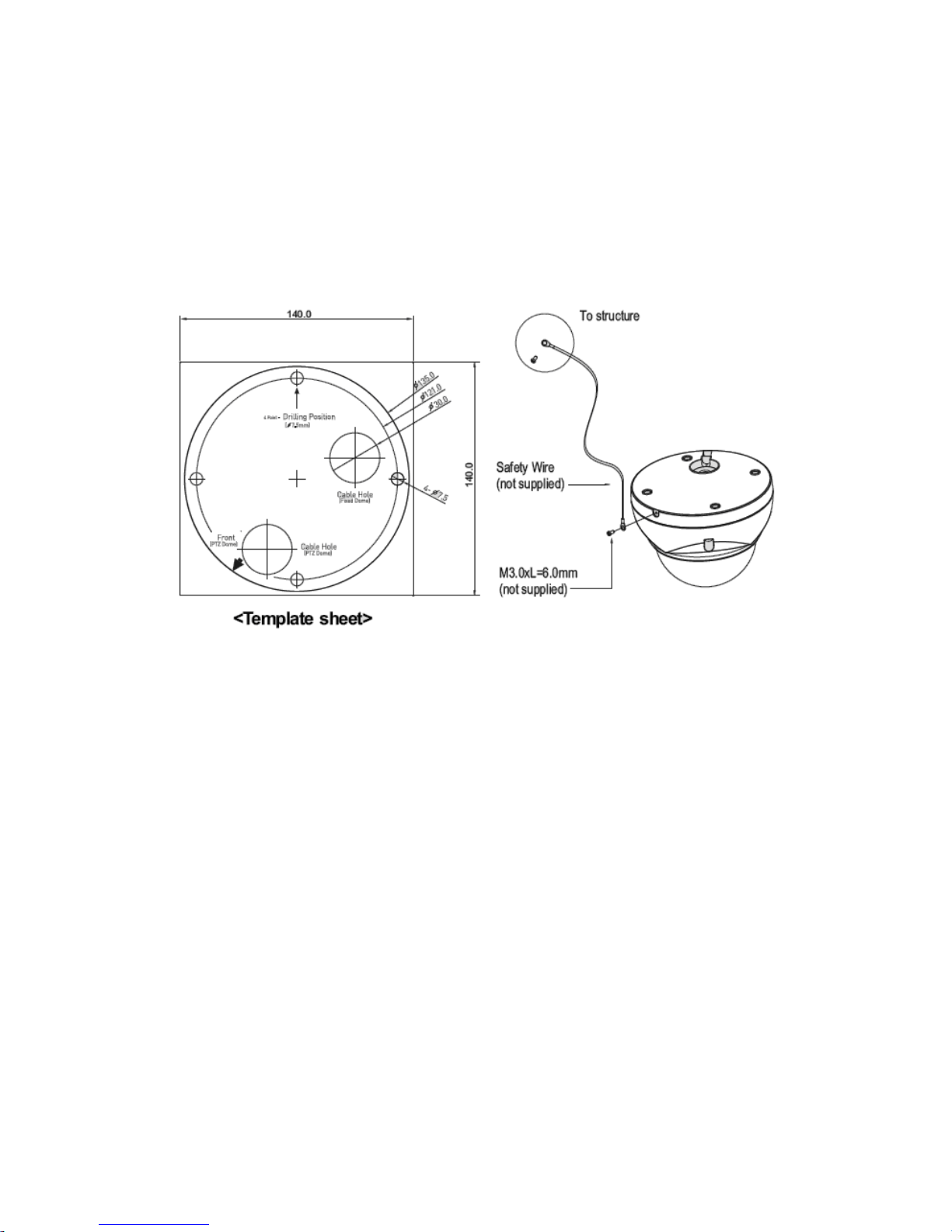
Base Installation
1. Drill mounting and cable holes in the place (ceiling) to which this dome camera is to be installed
using the supplied template sheet.
Warning: The total mass of the main unit is approx 1.3kg. Check whether the ceiling to which the
Dome Camera is installed is strong enough to hold the unit mass. If not, the Dome Camera could
fall, causing injury.
2. Attach the safety wire for securing the dome camera to ceiling.
3. Extract each wire through the cable hole, connect communication lines.
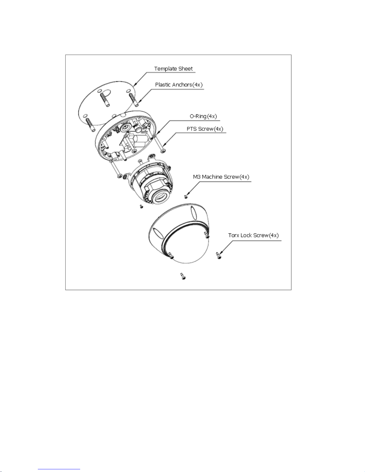
4. Unlock torx screws (4x) the dome cover and fix the dome case firmly with supplied mounting
screws (4x), plastic anchors (4x), O-Rings (4x).
5. Adjust desired focus and scene by turning and moving the hemisphere by hand.
6. Lock the housing cover with torx screws (4x).
VK2-1080VRD(IR)3V9(F) manual V1.0
13
Models equipped with IR LEDs only

VK2-1080VRD(IR)3V9(F) manual V1.0
14
Models equipped without IR LEDs only
VK2-1080VRD(IR)3V9(F) manual V1.0
15
2.2 Connection
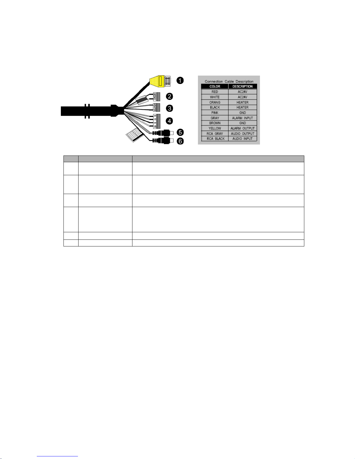
Connection Cable
NO
Connector Name
Description
1
Black
Ethernet, RJ-45 port compatible with 10/100Mbps having PoE
functionality. Modular Jack
2
Red:
AC24V/DC12V
White: AC24V/GND
Main Power, 3pin terminal, DC12V 470mA(4.0W) /
AC24V 5200mA(6.5W) with heater Off
3
Orange: AC24V
Black: AC24V
Heater Power, 3pin terminal, max. 25Watt @ AC24V
4
Pink: GND
Gray: Alarm Input
Brown: GND
Yellow: Alarm Out
Alarm Input and Output, 4pin terminal.
5
RCA Gray
Audio line output, RCA Jack
6
RCA Black
Audio line input, RCA Jack
Micro SD memory slot on the Board
Card Slot for Micro SD memory: Socket “J15”
• Connecting to the RJ-45
Connect a standard RJ-45 cable to the network port of the network camera. Generally a
cross-over cable is used for directly connection to PC, while a direct cable is used for connection
to a hub.
You can also use a router featuring PoE (Power over Ethernet) to supply power to the camera.
• Connecting Alarms
AI(Alarm In) :
You can use external devices to signal the network camera to react on events. Mechanical or
electrical switches can be wired to the AI (Alarm In) and G (Ground) connectors.
G(Ground) :
Connect the ground side of the alarm input and/or alarm output to the G (Ground) connector.
Alarm Out :
The network camera can activate external devices such as buzzers or lights. Connect the device
to the AO (Alarm Out) and G (Ground) connectors.
• Connecting the Power (If PoE is not being used)
Connect the power of DC12V or AC24V for the network camera. Connect the positive(+) pole to
the ‘+’ position and the negative(-) pole to the ‘-‘ position for the DC power.
Be careful not to reverse the polarity when you connect the power cable.
VK2-1080VRD(IR)3V9(F) manual V1.0
16
You can also use a router featuring PoE (Power over Ethernet) to supply power to the
camera.
The heater will operate properly only by the heater power source of AC 24V.
If using PoE, the heater will not operate at all.
Use an adaptor if the installation site requires heater operations. Adaptor is sold separately.
For the power specifications, refer to the “Appendix”. (page 75)
If PoE and DC 12V are both applied, this camera will get supplied with power from PoE.
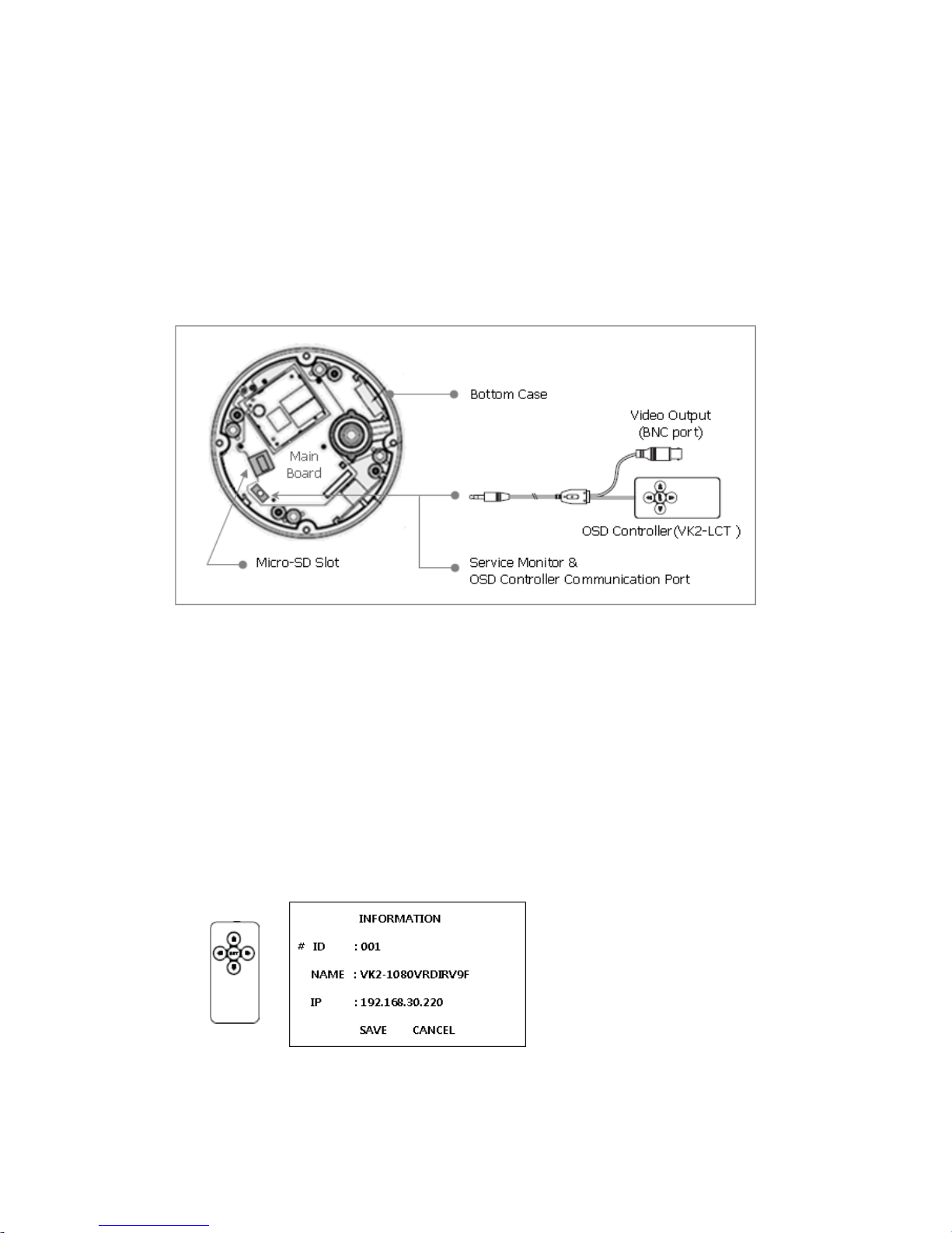
• Connecting Service Monitor Port (using VK2-LCT)
Service monitor output port (J3) is located on the board of the dome camera, and is used for an
easy OSD setup.
▶ ID & IP assignment
The VK2-LCT local commissioning tool is used for an easy OSD setup. To make changes in the
OSD menu, please use the OSD controller, this is an optional purchase. You can set Camera Title
and IP Address, using a standard analogue set up monitor such as the VTMPRO. Instruction for
use of the VK2-LCT is supplied with the unit.
1. Connect VK2-LCT to the Service Monitor port of the network camera.
2. Connect Service Monitor and the Video Output port of the VK2-LCT.
3. Press the SET button to access main Menu.
4. Change Camera ID, and IP Address. You can change the Name or Title and IP address of the
camera. Using the ↑↓←→ buttons on the VK2-LCT, you can change the parameters.
5. Select SAVE or CANCEL to exit the Main Menu.
Video Output is also used for an easy zoom and focus control when installing lens. Video Output
is restricted to 704x480(576) resolution.
▶ Zoom & Focus Control
VK2-1080VRD(IR)3V9(F) manual V1.0
17
The camera enters Zoom and Focus control mode as soon as connecting VK2-LCT to the
Service Monitor port.
-. Zoom Control: ↑(Zoom In), ↓(Zoom Out)
-. Focus Control: ←(Focus Near), →(Focus Far)
-. Smart Focus: Press and hold the SET button for 2 or more seconds. The camera readjusts
focus automatically.
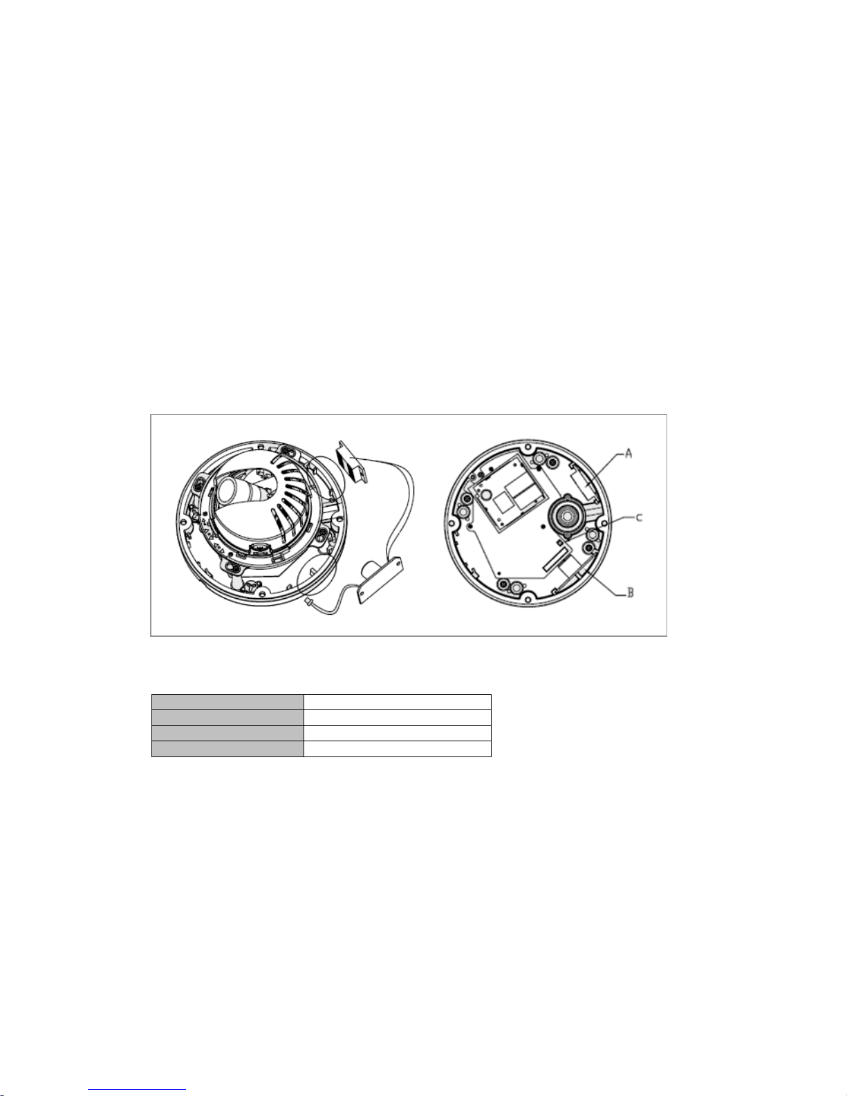
Heater Kit Installation(Optional)
1. Place the heater element is slot “A”. Please ensure that the cables are facing upwards and the
heater is pointing towards the Dome.
2. Place the PCB in slot “B”. Please ensure that the PCB is facing inside of the Dome with the
connection blocks at the top.
3. Place the plug in the Socket “C” (J3) which is found on the controller board.
• Heater (IF Applicable)
Power Supply
24VAC
Power Consumption
20Watt
Heater On
at 41°F (5°C)
Heater Off
at 59°F (15°C)
Note: The Heater module does not come equipped with the camera; however can be purchased as an
option.
VK2-1080VRD(IR)3V9(F) manual V1.0
18
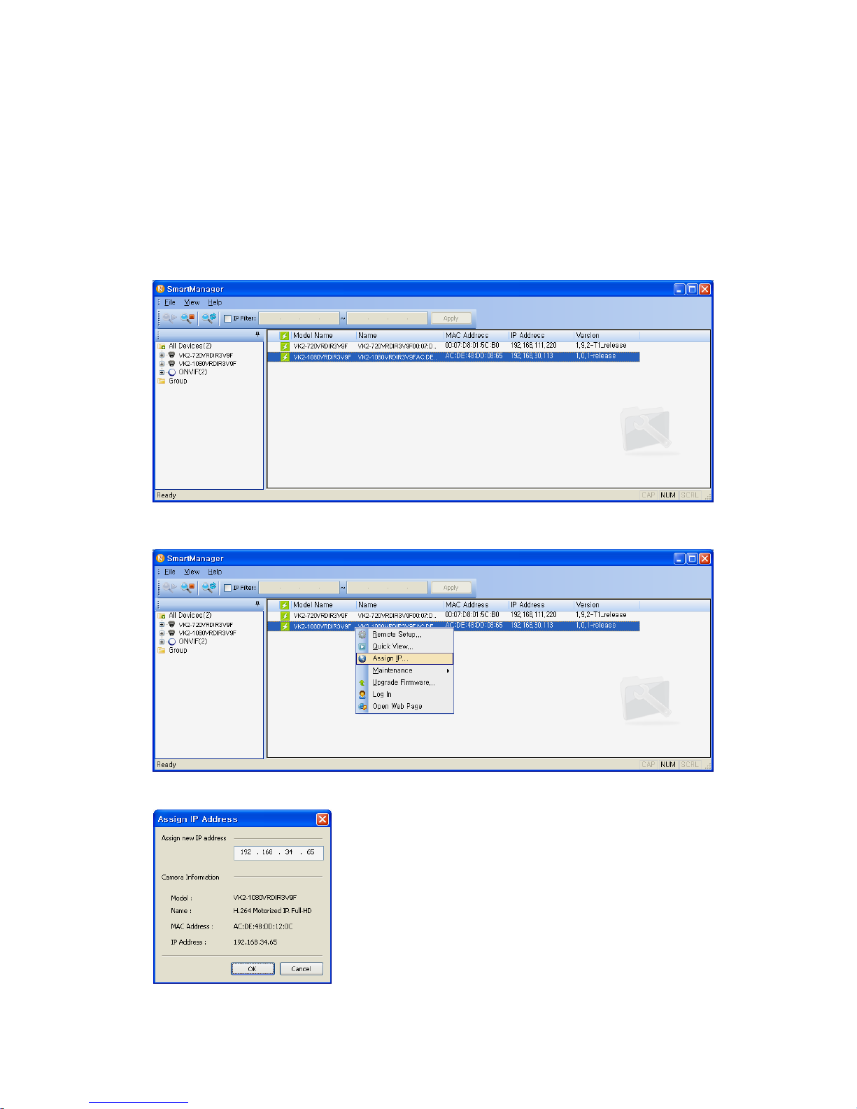
2.3 Network Connection and IP assignment
The Network Camera supports the operation through the network. When a camera is first connected to
the network it has no IP address. So, it is necessary to allocate an IP address to the device with the
“Smart Manager” utility on the CD. The factory default IP is “192.168.30.220”.
1. Connect the Network Camera / device to the network and power up.
2. Start SmartManager utility (Start>All Programs>SmartManager>SmartManager), the main window
will be displayed, after a short while any network devices connected to the network will be
displayed in the list.
3. Select the camera on the list and click right button of the mouse. You can see the pop-up menu
below.
4. Select Assign IP. You cam see a Assign IP window. Enter the required IP address.
Note: For more information, refer to the Smart Manger User’s
Manual
VK2-1080VRD(IR)3V9(F) manual V1.0
19
3. Operation
The Network Camera can be used with Windows operating system and browsers. The recommended
browsers are Internet Explorer, Safari, Firefox, Opera and Google Chrome with Windows.
Note: To view streaming video in Microsoft Internet Explorer, set your browser to allow ActiveX
controls.
3.1 Access from a browser
1. Start a browser (Internet Explorer).
2. Enter the IP address or host name of the Network Camera in the Location/Address field of your
browser.
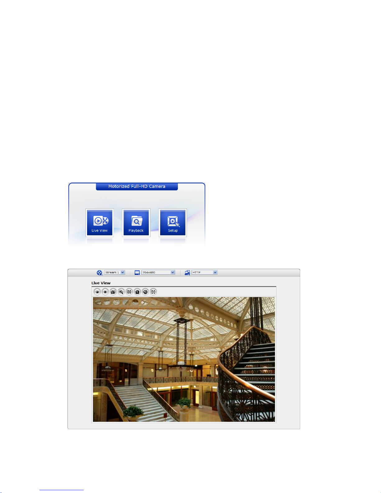
3. You can see a starting page. Click Live View, Playback or Setup to enter web page.
4. The network camera’s Live View page appears in your browser.
VK2-1080VRD(IR)3V9(F) manual V1.0
20
3.2. Access from the internet
Access from the internet once connected, the Network Camera is accessible on your local network
(LAN). To access the network camera from the Internet you must configure your broadband router to
allow incoming data traffic to the network camera. To do this, enable the NAT-traversal feature, which
will attempt to automatically configure the router to allow access to the network camera. This is
enabled from Setup > System > Network > NAT.
For more information, please see “3.5.5 System>Network>NAT” of User’s Manual.
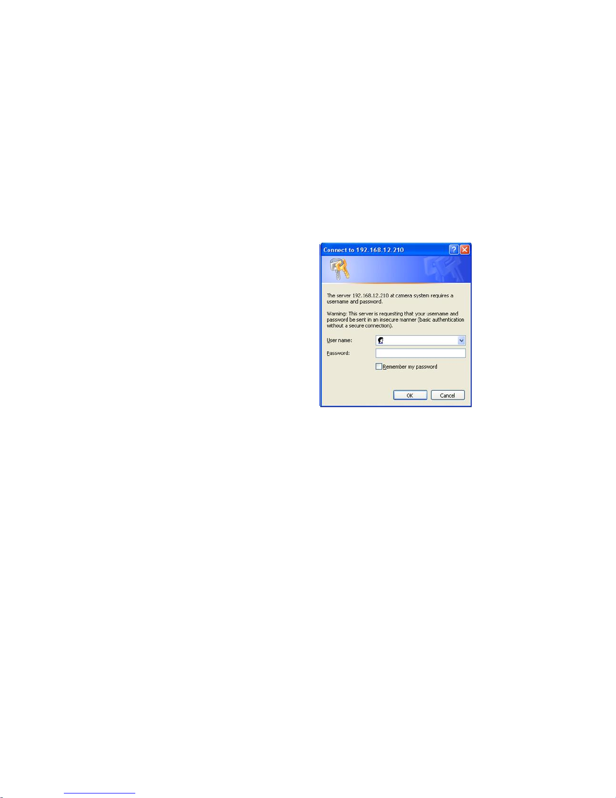
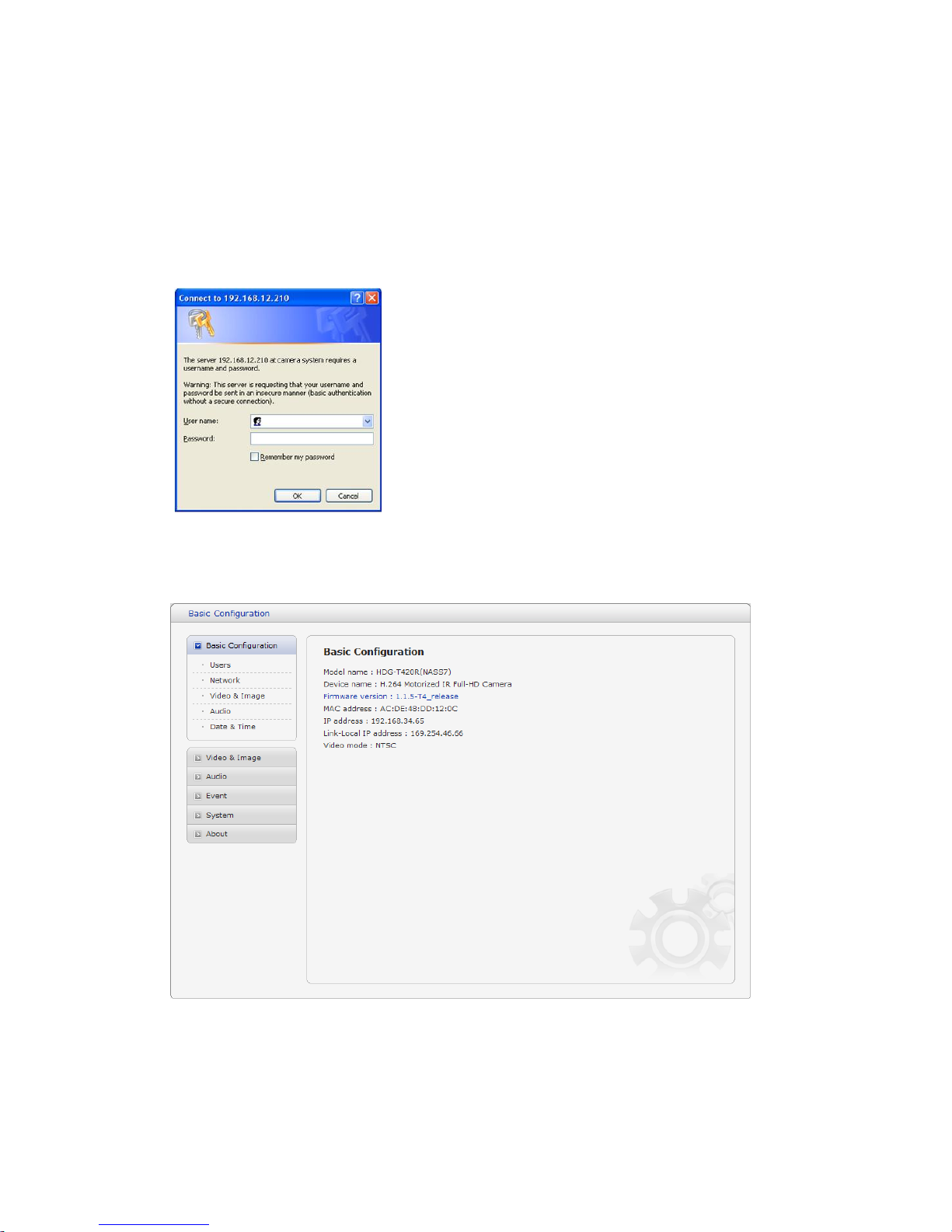
3.3 Setting the admin password over a secure connection
To gain access to the product, the password for
the default administrator user must be set. This is
done in the “Admin Password” dialog, which is
displayed when the network camera is accessed
for the setup at the first time. Enter your admin
name and password, set by the administrator.
Note: The default administrator username and
password is “admin”. If the password is lost, the
Network Camera must be reset to the factory
default settings. See “3.8 Resetting to the Factory
Default Settings” for more details.
To prevent network eavesdropping when setting the admin password, this can be done via an
encrypted HTTPS connection, which requires an HTTPS certificate (see note below).
To set the password via a standard HTTP connection, enter it directly in the first dialog shown below.
To set the password via an encrypted HTTPS connection, see “3.5.5 System > Security > HTTPS”.
Note: HTTPS (Hypertext Transfer Protocol over SSL) is a protocol used to encrypt the traffic between
web browsers and servers. The HTTPS certificate controls the encrypted exchange of information.
VK2-1080VRD(IR)3V9(F) manual V1.0
21
3.4 Live View Page
The live view page comes in several
screen modes: 1920x1080,
1280x1024, 1280x720, 704x480(576),
640x480, 352x240(288), and 320x240.
Users are allowed to select the most
suitable one out of those modes.
Please, adjust the mode in accordance
with your PC specifications and
monitoring purposes.
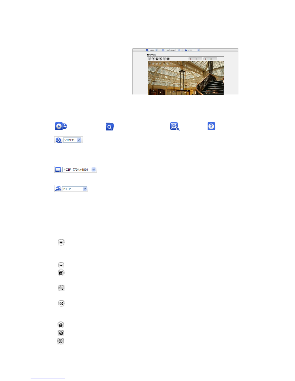
1) General controls
Live View Page Search & Playback Page Setup Page Help Page
The video drop-down list allows you to select a customized or pre-programmed
video stream on the live view page. Stream profiles are configured under Setup > Basic
Configuration > Video & Image. For more information, please see “3.5.1 Basic Configuration >
Video & Image” of User’s Manual.
The resolution drop-down list allows you to select the most suitable one
out of video resolutions to be displayed on live view page.
The protocol drop-down list allows you to select which combination of
protocols and methods to use depends on your viewing requirements, and on the properties of
your network.
2) Control toolbar
The live viewer toolbar is available in the web browser page only. It displays the following buttons:
The Stop button stops the video stream being played. Pressing the key again toggles the
start and stop. The Start button connects to the network camera or start playing a
video stream.
The Pause button pause the video stream being played.
The Snapshot button takes a snapshot of the current image. The location where the
image is saved can be specified.
The digital zoom activates a zoom-in or zoom-out function for video image on the live
screen.
The Full Screen button causes the video image to fill the entire screen area. No other
windows will be visible. Press the 'Esc' button on the computer keyboard to cancel full
screen view.
The Manual Trigger button activates a pop-up window to manually start or stop the event.
The Remote Focus button enables users to adjust focus and zoom remotely via network.
The Smart Focus button readjusts focus automatically.
VK2-1080VRD(IR)3V9(F) manual V1.0
22
Use this scale to control the volume of the speakers.
Use this scale to control the volume of the microphone.
Use this scale to control the volume of the speakers and microphones.
3) Video Streams
The Network Camera provides several images and video stream formats. Your requirements and
the properties of your network will determine the type you use.
The Live View page in the Network Camera provides access to H.264, MPEG-4 and Motion
JPEG video streams, and to the list of available video streams. Other applications and clients can
also access these video streams/images directly, without going via the Live View page.
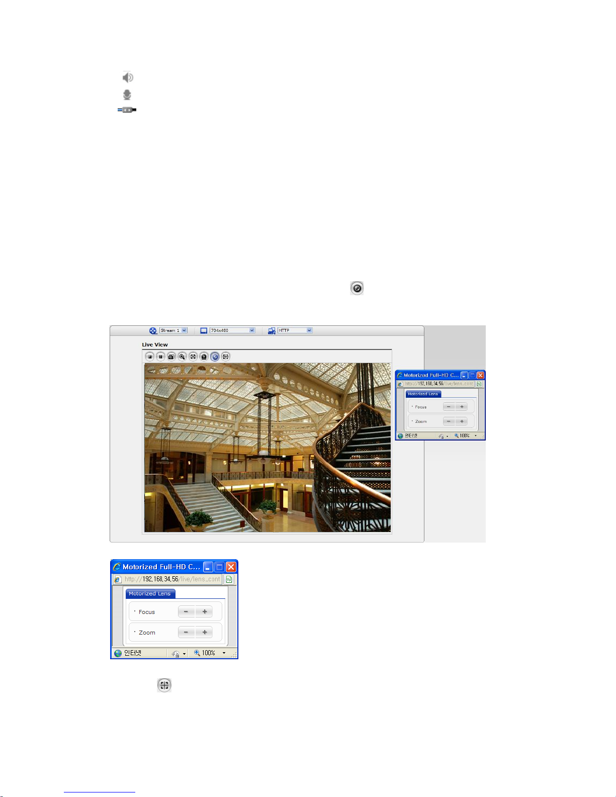
4) Focus and Zoom Control (Models equipped with Motorized Lens only)
You can control Zoom and Focus in the live screen. Press the button on the left top in the live
screen to activate the Zoom & Focus control panel.
• Adjusting Zoom:
Click “–“ button to zoom out and click “+” button to zoom in.
The focus is moved slightly after adjusting zoom; adjust the
focus again, as necessary.
• Adjusting Focus:
Click “–“ button for far focus and click “+” button to near focus.
Note: Click the button in the live screen to set the focus to the optimum position.
VK2-1080VRD(IR)3V9(F) manual V1.0
23
3.5 Setup
This section describes how to configure the network camera, and is intended for product
Administrators, who have unrestricted access to all the Setup tools; and Operators, who have access
to the settings for Basic, Live View, Video & Image, Audio, Event, and System Configuration.
You can configure the network camera by clicking Setup in the top right-hand corner of the Live View
page. Click on this page to access the online help that explains the setup tools
When accessing the Network Camera for the first
time, the “Admin Password” dialog appears. Enter
your admin name and password, set by the
administrator.
Note: If the password is lost, the Network Camera
must be reset to the factory default settings. See “3.8
Resetting to the Factory Default Settings”.
3.5.1 Basic Configuration
Device information is displayed on this page.
VK2-1080VRD(IR)3V9(F) manual V1.0
24
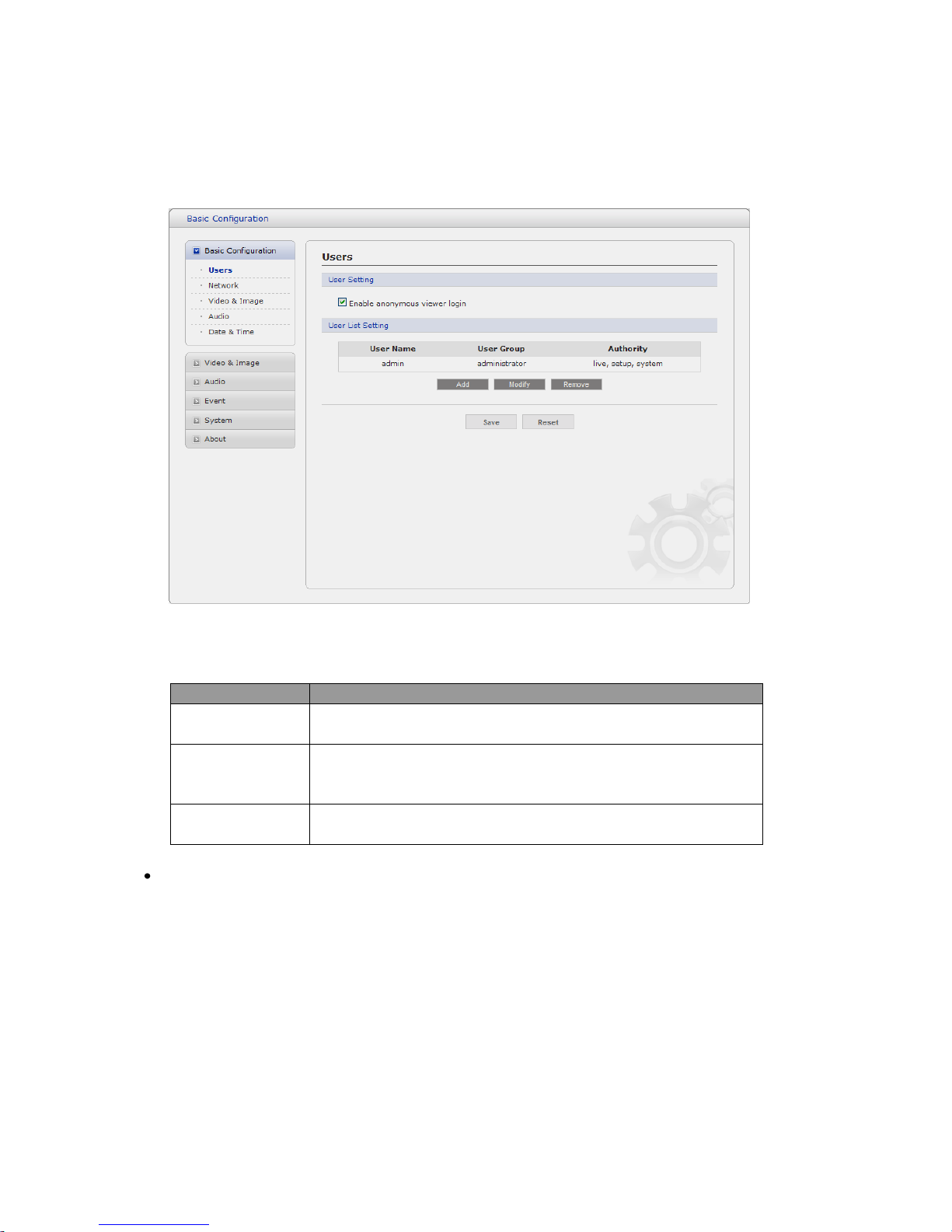
1) Users
User access control is enabled by default. An administrator can set up other users, by giving these
user names and passwords. It is also possible to allow anonymous viewer login, which means that
anybody may access the Live View page, as described below:
The user list displays the authorized users and user groups (levels):
User Group
Authority
Guest
Provides the lowest level of access, which only allows access to
the Live View page.
Operator
An operator can view the Live View page, create and modify
events, and adjust certain other settings. Operators have no
access to System Options.
Administrator
An administrator has unrestricted access to the Setup tools and
can determine the registration of all other users.
Enable anonymous viewer login: Check the box to use the webcasting features. Refer to “3.5.2
Video & Image” for more details.
2) Network
The network camera supports both IP version 4 and IP version 6. Both versions may be enabled
simultaneously, and at least one version must always be enabled. When using IPv4, the IP address
for the network camera can be set automatically via DHCP, or a static IP address can be set manually.
If IPv6 is enabled, the network camera receive an IP address according to the configuration in the
network router. There is also the option of using the Internet Dynamic DNS Service. For more
information on setting the Network, please see Setup> System>Security>Network.
 Loading...