

Vip2 VK2-1080VRD3V9, VK2-1080VRD3V9F, VK2-1080VRDIR3V9F Installation Manual
VK2-1080VRD(IR)3V9(F)
Installation Guide

2
3
1. Description
This manual applies to the VK2-1080VRDIR3V9F, VK2-1080VRD3V9F and VK2-1080VRD3V9
These domes are fully featured Vandal resistant day/night IP cameras
Model Name
Features
VK2-1080VRD3V9
Varifocal Lens
No IR LED
VK2-1080VRD3V9F
Motorized Varifocal Lens
No IR LED
VK2-1080VRDIR3V9F
Motorized Varifocal Lens
Built-in 24 IR LEDs
• Installation Steps
Follow these steps to install the network camera on your local network (LAN):
1. Check the package contents against the list below.
2. Connect the Network Camera.
3. Set an IP address.
4. Set the password.
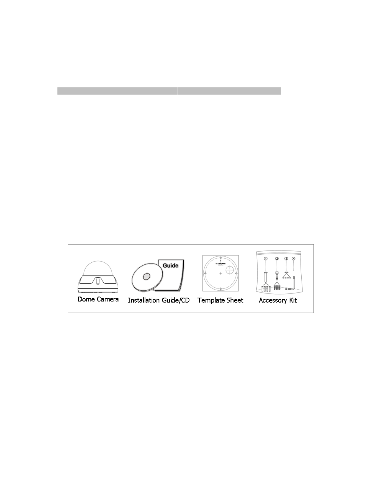
• Package Component
The system comes with the following components:
• Contents in the installation CD
1. The DOMEUser’s Manual
2. The SmartManager User’s Manual
3. The VIP2 Client User’s Manual
4. The SmartManager Installation software
5. The VIP2 Installation software
Note: Check your package to make sure that you received the complete system, including all
components shown above.
4
2. Installation
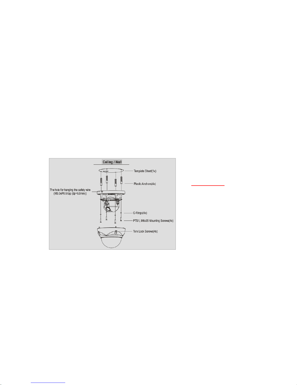
2.1 Base Installation
1. Position the supplied template in the mounting location, use this template to drill the
required mounting holes and cable access holes
NOTE
The total mass of the main unit is approx 1.3kg. Check whether the ceiling to which the
Dome Camera is installed is strong enough to hold the unit mass. If not, either mount in a
different position or strengthen the ceiling.
2. Attach safety wire for securing the dome camera to ceiling or structure.
3. Insert each cable through the cable hole, connect BNC cable and communication lines.
4. Unlock (4x) torx screws on the dome cover and fix the dome case firmly with supplied
mounting screws (4x), plastic anchors (4x), O-Rings (4x).
5. Adjust desired focus and scene by turning and moving the hemisphere by hand.
6. Replace the housing cover and secure with the torx screws (4x).
As a minimum the dome requires the connection of a network cable, if a PoE switch is used this cable
can supply power as well as transmit the video. If a PoE switch is not available then a separate power
supply is required
Important note:
The O-Rings(4X) form the
primary waterproofing seal, and
must be included in the
installation process
 Loading...