

Vip2 VK2-1080BXDN Configuration And User Manual
1
VK2-1080BXDN
Configuration and user manual
VK2-1080BXDN manual V1.0
2
WARNING
TO REDUCE THE RISK OF FIRE OR ELECTRIC SHOCK, DO NOT EXPOSE THIS PRODUCT TO RAIN OR
MOISTURE. DO NOT INSERT ANY METALLIC OBJECTS THROUGH THE VENTILATION GRILLS OR
OTHER OPENINGS ON THE EQUIPMENT.
CAUTION
EXPLANATION OF GRAPHICAL SYMBOLS
The lightning flash with arrowhead symbol, within an equilateral triangle, is intended to alert
the user to the presence of un -insulated "dangerous voltage" w ithin the product's enclosure
that may be of sufficient magnitude to constitute a risk of electric shock to persons.
The exclamation point within an equilateral triangle is intended to alert the user to the
presence of important operating and maintenance (servicing) instructions in the literature
accompanying the product.
PRECAUTIONS
Safety ---------------------------------- Installation -----------------------------
Cleaning ----------------------------------
CAUTION
RISK OF ELECTRNIC SHOCK
DO NOT OPEN
CAUTION: TO REDUCE THE RISK OF ELECTRIC SHOCK,
DO NOT REMOVE COVER (OR BACK).
NO USER-SERVICEABLE PARTS INSIDE.
REFER SERVICING TO QUALIFIED SERVICE PERSONNEL.
Should any liquid or solid object fall into the cabinet,
unplug the unit and have it checked by the qualified
personnel before operating it any further.
Unplug the unit from the wall oulet if it is not goin g to
be used for several days or more. To disconnect the
cord, pull it out by the plug. Never pull the cord itself.
Allow adequate air circulation to prevent internal heat
build -up. Do not place the unit on surfaces (rugs,
blankets, etc.) or near materials (curtains, draperies)
that may block the ventilation holes.
Height and vertical linearity controls located at the rear
panel are for special adjustments by qualified
personnel only.
Do not install the unit in an extremely hot or humid place
or in a place subject to excessive dust, mechanical
vibration.
The unit is not designed to be waterproof.
Exposure to rain or water may damage the unit.
Clean the unit with a slightly damp soft cloth.
Use a mild household detergent. Never use strong
solvents such as thinner or benzene as they might
damage the finish of the unit.
Retain the original carton and packing materials for safe
transport of this unit in the future.

3
CE COMPLIANCE STATEMENT
WARNING
This is a Class A product. In a domestic environment this product may cause radio interference in
which case the user may be required to take adequate measures.
CAUTION
RISK OF EXPLOSION IF BATTERY IS REPLACED BY AN INCORRECT TYPE.
DISPOSE OF USED BATTERIES ACCORDING TO THE INSTRUCTIONS

VK2-1080BXDN manual V1.0
4
IMPORTANT SAFETY INSTRUCTIONS
1. Read these instructions.
2. Keep these instructions.
3. Heed all warnings.
4. Follow all instructions.
5. Do not use this apparatus near water.
6. Clean only with dry cloth.
7. Do not block any ventilation openings. Install in accordance with the
Manufacturer’s instructions.
8. Do not install near any heat sources such as radiators, heat registers, stoves, o
r other apparatus (including amplifiers) that produce heat.
9. Do not defeat the safety purpose of the polarized or grounding-type plug.
A polarized plug has two blades with one wider than the other. Grounding
type plug has two blades and a third grounding prong. The wide blade or the
third prong are provided for your safety. If the provided plug does not fit into
your outlet, consult an electrician for replacement of the obsolete outlet.
10. Protect the power cord from being walked on or pinched particularly at plugs
convenience receptacles, and the point where they exit from the apparatus.
11. Only use attachments/accessories specified by the manufacturer.
12. Use only with the cart, stand, tripod, bracket, or table
specified by the manufacturer, or sold with the apparatus.
When a cart is used, use caution when moving the
cart/apparatus combination to avoid injury from tip-over.
13. Unplug this apparatus during lightning storms or when
unused for long periods of time.
14. Refer all servicing to qualified service personnel. Servicing is
required when the apparatus has been damaged in any way, such as power-
supply cord or plug is damaged, liquid has been moisture, does not operate
normally, or has been dropped.
15. CAUTION – THESE SERVICING INSTRUCTIONS ARE FOR USE BY
QUALIFIED SERVICE PERSONNEL ONLY. TO REDUCE THE RISK
OF ELECTRIC SHOCK DO NOT PERFORM ANY SERVICING OTHER
THAN THAT CONTAINED IN THE OPERATING INSTRUCTIONS
UNLESS YOU QRE QUALIFIED TO DO SO.
16. Use satisfy clause 2.5 of IEC60950-1/UL60950-1 or Certified/Listed Class
2 power source only.
17. ITE is to be connected only to PoE networks without routing to the outside plant.

5
CONTENTS
DESCRIPTION ----------------------------------------------------------------------------------------------------7
Key Features --------------------------------------------------------------------------------------------7
Components --------------------------------------------------------------------------------------------8
Camera Layout ----------------------------------------------------------------------------------------9
INSTALLATION ---------------------------------------------------------------------------------------------------11
Before Installation -------------------------------------------------------------------------------------11
Starting Installation ------------------------------------------------------------------------------------11
DC Auto Iris Lens Installation & Adjustment -------------------------------------------------------12
Audio Connection --------------------------------------------------------------------------------------13
Alarm Connection --------------------------------------------------------------------------------------13
OPERATION -------------------------------------------------------------------------------------------------------14
Minimum conditions for using web browser -------------------------------------------------------14
Accessing the IP camera ------------------------------------------------------------------------------14
Main Menu ----------------------------------------------------------------------------------------------15
LIVE VIEW --------------------------------------------------------------------------------------------------------16
Live Video Page Icons ---------------------------------------------------------------------------------16
PLAYBACK ---------------------------------------------------------------------------------------------------------18
Playback View ------------------------------------------------------------------------------------------18
SETUP --------------------------------------------------------------------------------------------------------------21
Users -----------------------------------------------------------------------------------------------------22
Network -------------------------------------------------------------------------------------------------25
Image ----------------------------------------------------------------------------------------------------27
Audio -----------------------------------------------------------------------------------------------------29
Date & Time --------------------------------------------------------------------------------------------31
Live View – Source ------------------------------------------------------------------------------------33
Image – Basic ------------------------------------------------------------------------------------------36
Image – AE & AWB ------------------------------------------------------------------------------------38
Image – Day & Night ----------------------------------------------------------------------------------40
Image – WDR & 3D-DNR -----------------------------------------------------------------------------42
Image – Privacy Mask ---------------------------------------------------------------------------------45
Video & Image – Stream1 ----------------------------------------------------------------------------47
Video & Image – Stream2 ----------------------------------------------------------------------------49
Video & Image – Stream3 ----------------------------------------------------------------------------51
Video & Image – Stream4 ----------------------------------------------------------------------------54
Video & Image – Webcasting ------------------------------------------------------------------------57
Audio – Basic -------------------------------------------------------------------------------------------58
Event In – Alarm-In ------------------------------------------------------------------------------------60
Event In – Manual Trigger ----------------------------------------------------------------------------62
Event In – VMD Stream1 -----------------------------------------------------------------------------63

VK2-1080BXDN manual V1.0
6
Event In – VMD Stream3 -----------------------------------------------------------------------------65
Event In – VMD Stream4 -----------------------------------------------------------------------------67
Event Out – SMTP --------------------------------------------------------------------------------------69
Event Out – FTP& JPEG -------------------------------------------------------------------------------71
Event Out – HTTP Server -----------------------------------------------------------------------------73
Event Out – Audio Alert -------------------------------------------------------------------------------75
Event Out – Audio Alert – Audio Recorder -------------------------------------------------------76
Event Out – PTZ Preset--------------------------------------------------------------------------------78
Event Out – Record ------------------------------------------------------------------------------------79
Event Map -----------------------------------------------------------------------------------------------80
Event Map – Add ---------------------------------------------------------------------------------------82
Device – PTZ --------------------------------------------------------------------------------------------85
Device – RS485 -----------------------------------------------------------------------------------------86
Security – Users ----------------------------------------------------------------------------------------87
Security – HTTPS -------------------------------------------------------------------------------------90
Security – IP Filtering --------------------------------------------------------------------------------92
Date & Time ------------------------------------------------------------------------------------------ 93
Network – Basic ---------------------------------------------------------------------------------------95
Network – DDNS --------------------------------------------------------------------------------------97
Network – RTP ----------------------------------------------------------------------------------------98
Network – UPnP --------------------------------------------------------------------------------------100
Network – QoS ----------------------------------------------------------------------------------------101
Language ----------------------------------------------------------------------------------------------102
Maintenance -------------------------------------------------------------------------------------------103
Support -------------------------------------------------------------------------------------------------105
About ---------------------------------------------------------------------------------------------------106
Technical Specifications ---------------------------------------------------------------------------------------107
Image --------------------------------------------------------------------------------------------------107
Electrical / Connector --------------------------------------------------------------------------------107
Mechanical ---------------------------------------------------------------------------------------------107
Video ---------------------------------------------------------------------------------------------------107
Audio ---------------------------------------------------------------------------------------------------108
System Integration -----------------------------------------------------------------------------------108
Environmental -----------------------------------------------------------------------------------------109
Physical ------------------------------------------------------------------------------------------------109
Troubleshooting -------------------------------------------------------------------------------------------------110
Upgrading the Firmware -----------------------------------------------------------------------------110
General Troubleshooting ----------------------------------------------------------------------------110

7
DESCRIPTION
-------------------------------------------------------------------------------------------------------------------------------------
The VK2-1080BXDN camera is an internet protocol based megapixel network camera with a built-in
web based viewer on Internet Explorer®. The camera has a connection feature for third-party
applications and compatible with supplied Utility software for easy installation and Client software to
search, configure, manage, live view, record and playback.
The camera supports dual compression formats and multiple streaming simultaneously. The two
standard compression formats include H.264 and MJPEG. The multiple streams can be configured to
a variety of resolutions, bit rates and frame rates.
The camera uses 1/2.8 inch CMOS sensor and complies with CS mount lens and also supports PoE
(Power over Ethernet), DC12V, and AC24V.
Key Features
- HDTV Video Quality
The VK2-1080BXDN is capable of providing the outstanding image quality with HDTV performance
and profiles (High, Main, and Baseline) in H.264 compression.
- Multiple Streaming
Each stream can be programmed independently and transmitted using different configurations.
- ROI (Region of Interest)
The ROI features that transmit specially selected area in the primary stream using different FPS,
Resolution, Bit Rates and Picture Quality.
- WDR / BLC
The VK2-1080BXDN is capable of providing the Wide Dynamic Range / Back Light Compensation
function to view the object clearly in backlight conditions.
- 3D-DNR
3Dimensional-Digital Noise Reduction technology dramatically cleans up the noise in video frames
and solves the problem of low- light sensitivity where it can display high image resolution even in
extremely low light conditions.
- DIS
Digital Image Stabilization function minimizes the appearance of shaky images caused by low-
frequency vibration.
- Day and Night
The VK2-1080BXDN provides clear monitoring images even in low light conditions using IR-cut filter.

VK2-1080BXDN manual V1.0
8
- Easy Focus
Easy Focus helps to reduce the installation efforts especially video image focusing of the camera.
- Dual Codec (H.264, MJPEG)
The VK2-1080BXDN supports two standard compressions formats H.264 and MJPEG.
- Digital PTZ
Supports maximum 10x digital zoom.
- Intelligent Video Motion Detection
The VK2-1080BXDN offers intelligent & sophisticated video motion detection for each multiple
streams.
- Triple Power (Power over Ethernet, DC12V, AC24V)
This camera supports Power over Ethernet (PoE), which supplies power to the camera through the
network. If the network has not PoE, connect a DC12V or AC24V power connector.
- SD Local Recording
The VK2-1080BXDN provides local video recording function. When camera detects video motion or
alarm events or manual trigger, it can record video stream by itself.
- Voice Alert Linked to Alarm Detection
The VK2-1080BXDN can play the audio file stored in the camera in synchronization with alarm
detection by the sensor input or the motion detection function.
- Network Flow Control
The VK2-1080BXDN provides a flow control function which enhances network efficiency by
significantly restricting user video streams with designating the maximum bandwidth.
- ONVIF Certificate
The VK2-1080BXDN network camera complies with the ONVIF certificate. ONVIF (Open Network
Video Interface Forum) is an open industry forum for the development of a global standard for the
interface of network video products.
Components
Quantity Description
1 Camera
1 Installation CD
1 C- Mount Ring
1 Auto DC-Iris Connector
NOTE
Lens, installation hardware and Adapter for DC12V / AC24V are not supplied.
9
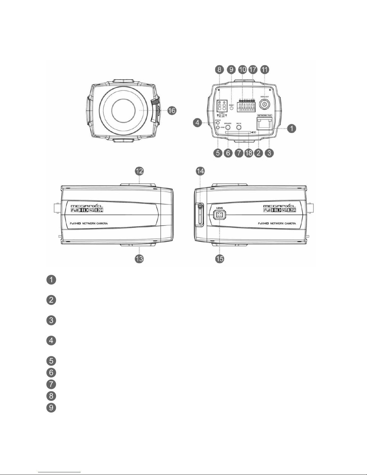
Camera Layout
RJ-45 connector: Supplies power to the camera through the network using PoE. If PoE is not
available, supplies DC12V or AC24V power source to the POWER connector.
ETHERNET link indication LED: Flashes green to indicate that data is being TX/RX by the
camera.
ETHERNET activity indication LED: Glows solid amber to indicate that a live connection is
established.
STATUS indication LED: Flashes amber about one time per second to indicate normally
working and flashes green about 2~3 time per second while upgrade.
POWER indication LED: Glows solid red if power is supplied properly.
SPEAKER connector: Connect external speaker for audio output.
MIC connector: Supplies external microphone as an audio input source.
POWER connection: Supplies DC12V or AC24V as the power source comply with Class2.
RESET button: Restores the camera’s factory default settings. This button is recessed. Use a
small tool, such as a paper clip, to press the reset button.
To reset the camera:

VK2-1080BXDN manual V1.0
10
1. Power off
2. Press and hold the RESET button
3. Supply the camera with power
4. Hold the RESET button for 15 seconds
ALARM connection: Connect one or two physical alarm input signal into the device and one
alarm output signal that can be used to control an external alarm circuit.
BNC connector: Connect BNC cable for composite video output.
Top bracket connector: 0.25 Inch (0.64cm) UNC-20 screw, top of camera housing.
Bottom bracket connector: 0.25 Inch (0.64cm) UNC-20 screw, bottom of camera housing.
FOCUS ADJUSTING / FIXING screw: Tighten this screw after focus the lens of a camera.
AUTO IRIS LENS connector: Connect the DC auto iris lens 4-pin connector into this
connector to control the amount of light allowed through the lens.
CS MOUNT LENS: connection: Attach the CS type lens.
RS485 connection: Connect RS485 compatible device for PTZ control.
SD Card: Insert SD card for local recording.

11
INSTALLATION
-------------------------------------------------------------------------------------------------------------------------------------
Before Installation
Before installing the camera, thoroughly familiarise yourself with the information in this section of
the manual.
- It is recommended to connect the camera to a network that uses a DHCP (Dynamic Host
Configuration Protocol) server to address devices.
- To ensure secure access to the IP camera, place the camera behind a firewall when it is
connected to a network.
NOTES
- Use megapixel lens for higher image quality.
- Megapixel lenses are designed and tested to deliver optimal image quality to the VK2-1080BXDN
megapixel cameras.
- If the standard definition lens was installed on megapixel camera, the image quality will be poor
than expected.
- Recommend Lenses - VDD31V812IRP-3MP (Direct drive iris)
VM31V812IRP-3MP (Manual iris)
Starting Installation
1. Install the Lens
- Ensure the lens does not touch camera CCD sensor.
- If DC auto iris lens is required, connect DC auto iris 4-pin connector into iris drive connector
located on the side of the camera.
2. Mount the camera
The camera can be mounted from both top and bottom.
3. Connect other peripheral devices
Connect the other peripheral devices such as Alarm, Audio and BNC connector.
4. Supply the camera with power.
- If PoE is not available, connect DC12V or AC24V wires to the camera power connector. Ensure
correct polarity when using DC12V. Use a Class2 power.
- This camera complies with IEEE802.3af standard. Hence the power for the camera can be
supplied via Ethernet cabling without additional power supply.
- The camera will complete a configuration process within approximately 40 seconds. The amber
LED flashes once per second after the configuration process is complete.
5. View the camera image
View the camera image using the BNC connector or built-in web browser or supplied Client software.
NOTE
This camera will autosense and work with either a straight Ethernet cable or crossover Ethernet
cable.
VK2-1080BXDN manual V1.0
12
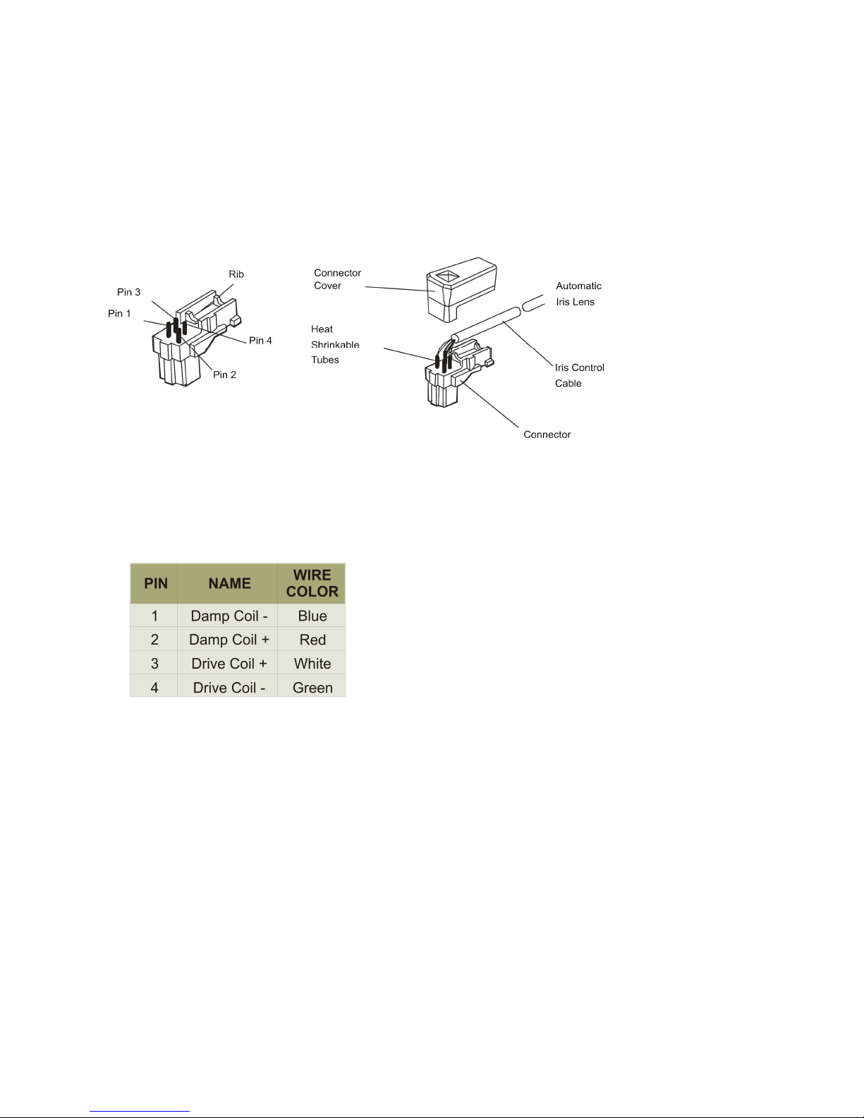
DC Auto Iris Lens Installation & Adjustment
The camera supports DC-type auto iris lenses. Perform the following steps to install and adjust a
DC-type auto iris lens.
- Solder the lens control wires to the connector supplied with the camera.
Figure 1. 4-Pin iris driver connector
- Attach the DC-type auto iris lens to the lens mount on the front of the camera.
- Plug the connector into the auto iris jack on the side of the camera. The connector is polarized
and can only be inserted into the iris jack one way.
Figure 2. DC auto iris Lens connection
13
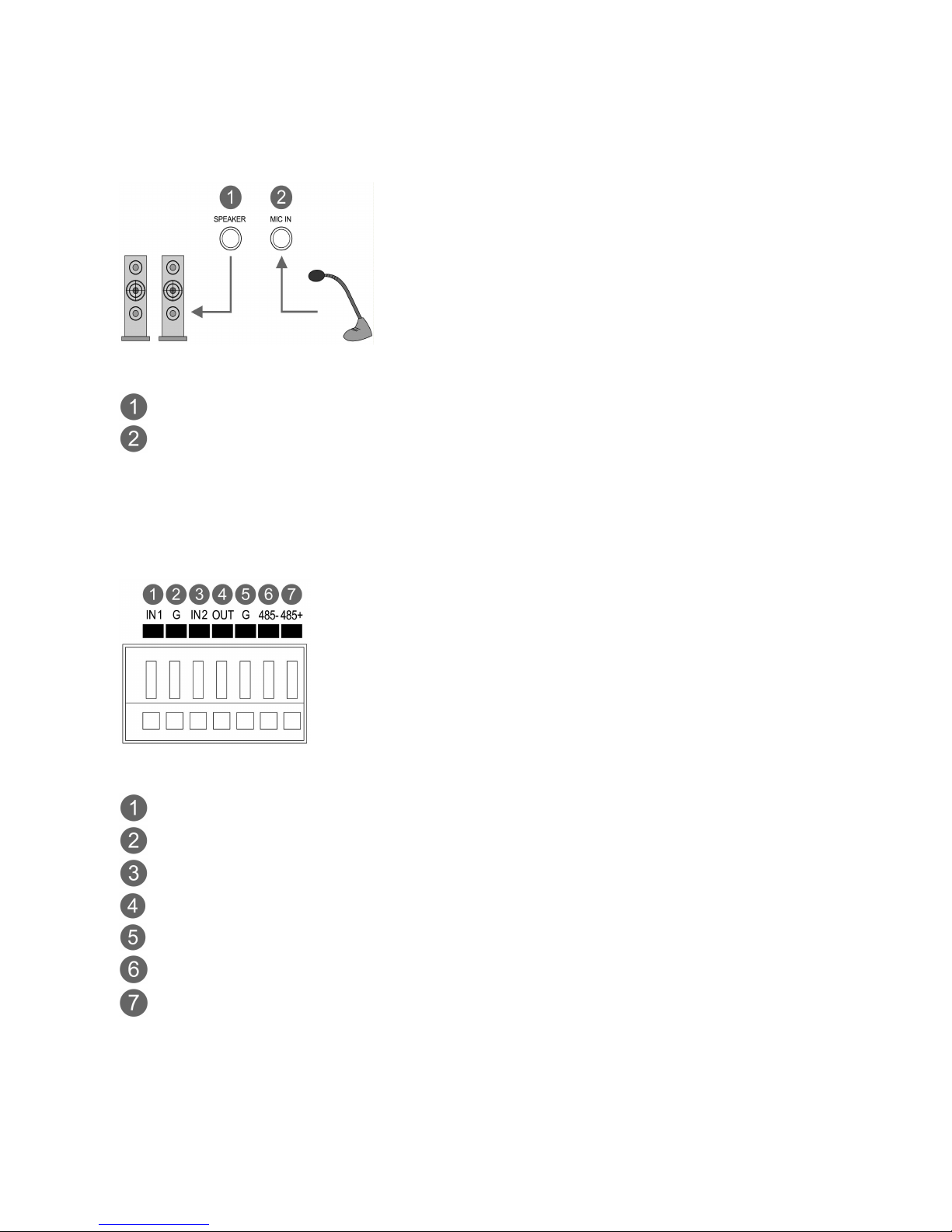
Audio Connection
This camera supports bidirectional audio. Install the microphone and a speaker with ampllifier
capability.
Figure 3. Audio connection
External Speaker
External Microphone
Alarm Connection
The camera provides two alarm input for external signalling devices and one alarm output for
activating external devices. Both Normally Open and Normally Closed devices are supported.
Figure 4. Alarm connector
Alarm Input 1
Alarm Ground
Alarm Input 2
Alarm Output
Alarm Ground
RS485 -
RS485 +
OPERATION

VK2-1080BXDN manual V1.0
14
-------------------------------------------------------------------------------------------------------------------------
Before powering up the camera, installation must be complete. The camera completes a
configuration sequence taking approximately 40 seconds from powering up. Once completed the
amber LED will flash once a second.
NOTES
- If the DHCP is enabled but the camera is not connected to a DHCP server, the camera will be set
default IP 192.168.30.220 and try to get IP from DHCP server about every two seconds.
- Network and processor bandwidth limitations might cause the video stream to pause or appear
pixelated when an increased number of Web-interface users connect to the camera. Decrease the
images per second, resolution, compression, or bit rate settings of the Web-interface video
streams to compensate for network or processor limitations.
Minimum conditions for using web browser
The minimum system requirements to use a Web browser with this IP camera are as follows:
- CPU: Pentium® 4 microprocessor, 2.0GHz
- Operational System: Windows XP® or Windows Vista® or Windows7®
- System Memory: RAM 512 Mbyte
- Ethernet: 100 Mbit
- Video Resolution: 1024(Horizontal) x 768(Vertical) pixels or higher
- Internet Explorer® 7 or later
- ActiveX® 1.0.0.13 or later
Accessing the IP camera
1. Open Web browser
2. Type IP address: - The default IP address is
192.168.30.220
NOTES
- If you do not know the camera’s IP address, install the SmartManager® utility software available
on the CD supplied with the product. The utility software will locate the assigned Model name,
Host name, MAC address, IP address, Version and others.
- Refer to the SmartManager® utility software manual for more detail.
3. Log On to the camera
Default User = admin, default password = admin
- Click the Live View icon for default live image view or the Setup icon to change the configuration
values.
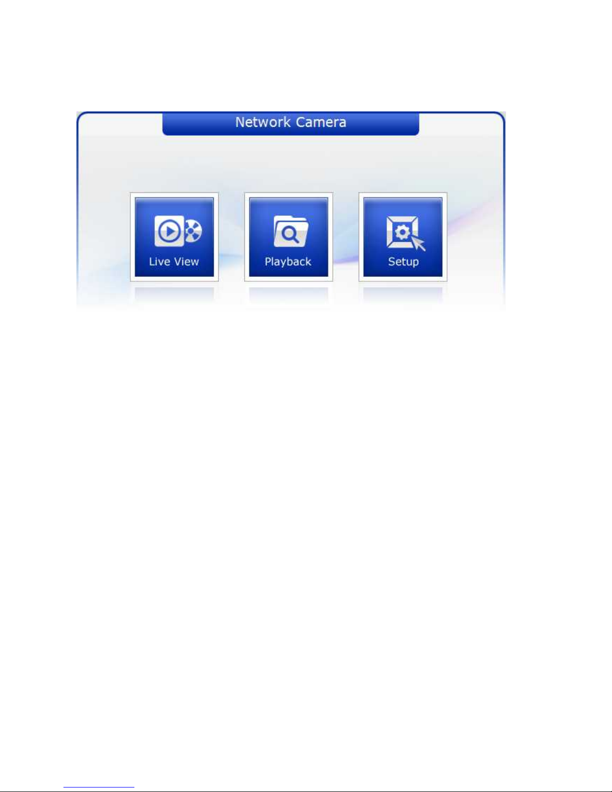
15
Main Menu
[Main Menu]
The dialog box will be appears.
- Type User ID and Password in the dialog box. The default User ID and Password are
admin
.
NOTE
For security purposes, be sure to change the password after you log on for the first time.
VK2-1080BXDN manual V1.0
16
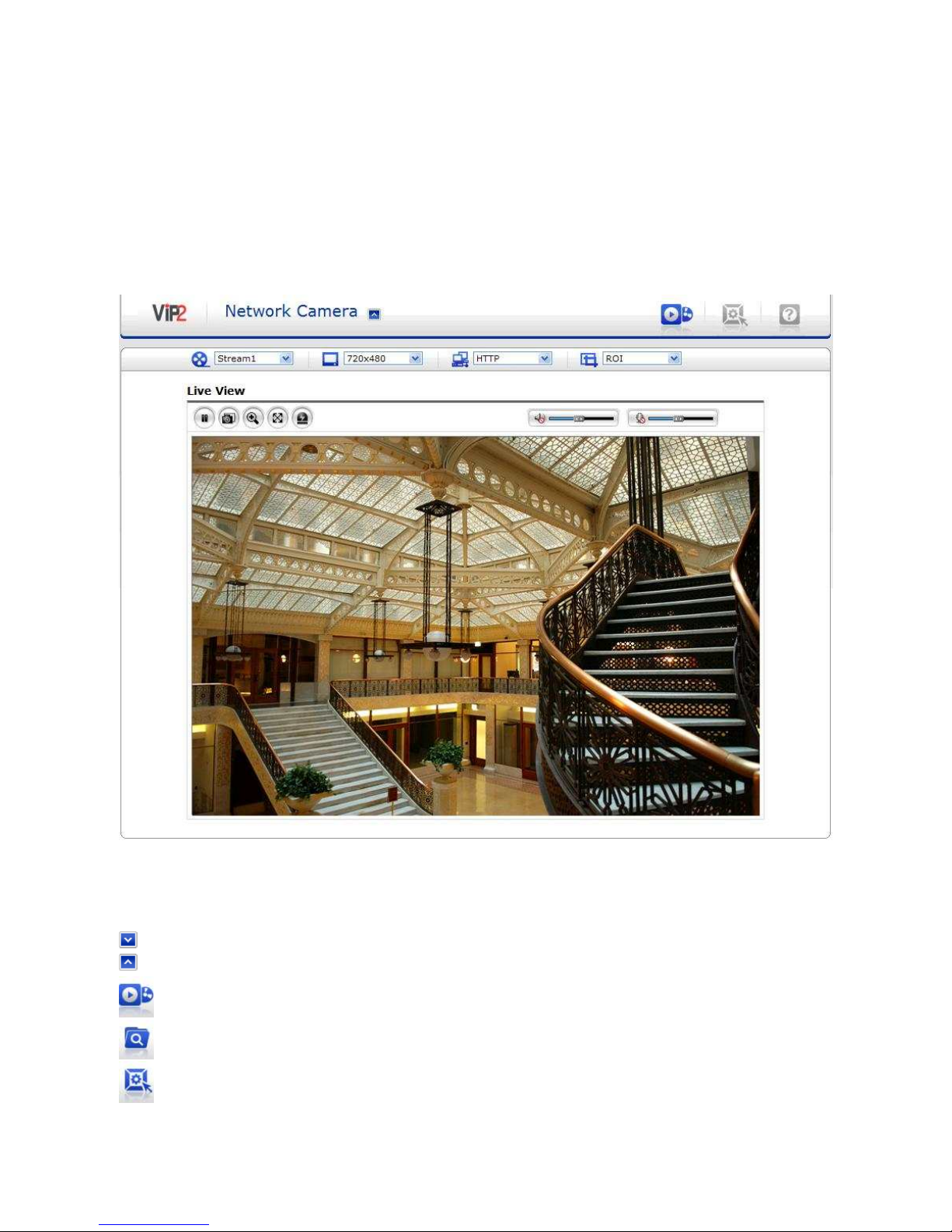
LIVE VIEW
-------------------------------------------------------------------------------------------------------------------------
The Live View page provides you to select the properties of video source. You can view the live
image from this page and also access the Setup menu and operate the main functions.
[ Main Live View Page]
Live Video Page Icons
Hide Main Icons: Hides main icons in the live view page.
Show Main Icons: Shows main icons in the live view page.
Live view: Displays live video stream.
Playback View: Enters playback menu. Required Micro SD card (not supplied)
Setup: Enters setup menu.

17
Help: Shows helpful information.
Source: Specify the viewable video stream source to display in live view page.
View Size: Specify the viewable video size to display in live view page.
Stream Type: Specify the internet protocol to display in live view page.
ROI View: Specify the specially selected area to transfer using different stream feature in the
primary video image. ROI is an abbreviation for “Region of Interest”.
Preset: Specify the Preset. This icon is inactivated if the PTZ settings are not set.
Pause: Pause the live video stream.
Snapshot: Take a picture of the video image currently on display. Supports the origin image
size view, Print, and Save feature.
Digital Zoom: Supports a digital zoom in live video image.
Full Screen: Expands video image to the entire screen area.
Manual Trigger: Activates the Alarm Out signalling manually.
Speaker: Adjusts the volume of Speaker and switch the sound on / off.
Microphone: Adjusts the volume of Microphone and switch the sound on /
off.
VK2-1080BXDN manual V1.0
18
PLAYBACK
-------------------------------------------------------------------------------------------------------------------------
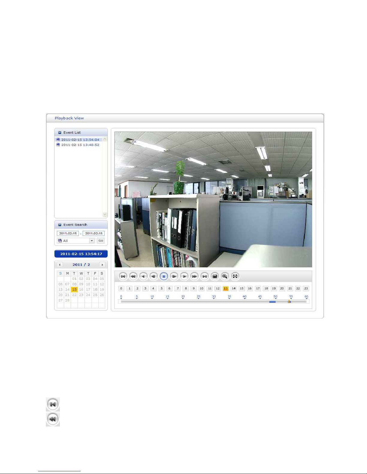
Playback View
Users can access the recorded images from the SD card via the web browser.
Figure 8. Playback View
Event List: Shows the recorded list of events.
Event Search: Select the start date and end date you want to playback, and then click the Go
button to show the list. The list can be tailored to show only one type or all events.
Calendar: Use the calendar to select a specific day
Playback Control Buttons: details below of individual icons
Go to the first.
Fast backward play
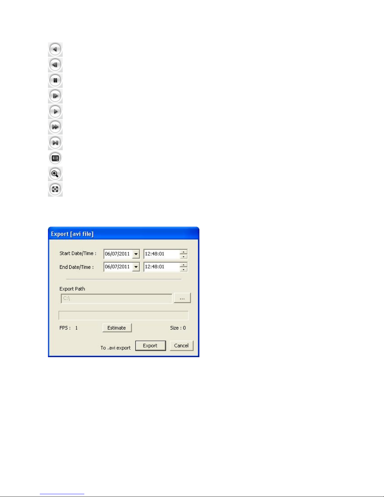
19
Backward play
Backward step
Pause
Forward step
Forward play
Fast forward play
Go to the last
Clip copy
Digital Zoom
Full Image
Clip Copy: Downloads an avi format file.
1. Select Start Date/Time and End Date/Time.
2. Set Export Path.
3. Click Estimate button which is shown the file FPS and Size.
4. Click Export or Cancel button.
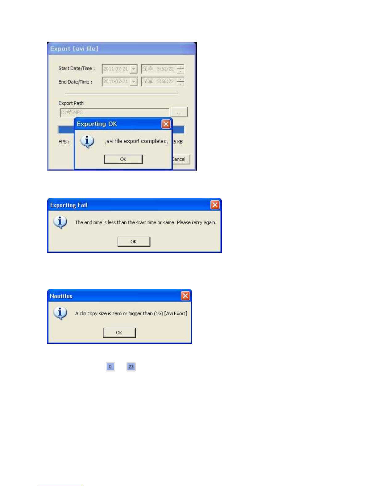
NOTES
1. If you set successfully, the following pop-up windows will be appeared.
VK2-1080BXDN manual V1.0
20
2. In case of mismatching of the Start or End Date/Time, the following windows will be appeared.
Please retry to set the Start or End Date/Time.
3. In case of no image data between the Start Date/Time and End Date/Time, the following
windows will be appeared.
Please retry to set the Start or End Date/Time.
4. The buttons from to indicate an Hours and the number from 0 to 60 indicate a minutes.
21
SETUP
-------------------------------------------------------------------------------------------------------------------------
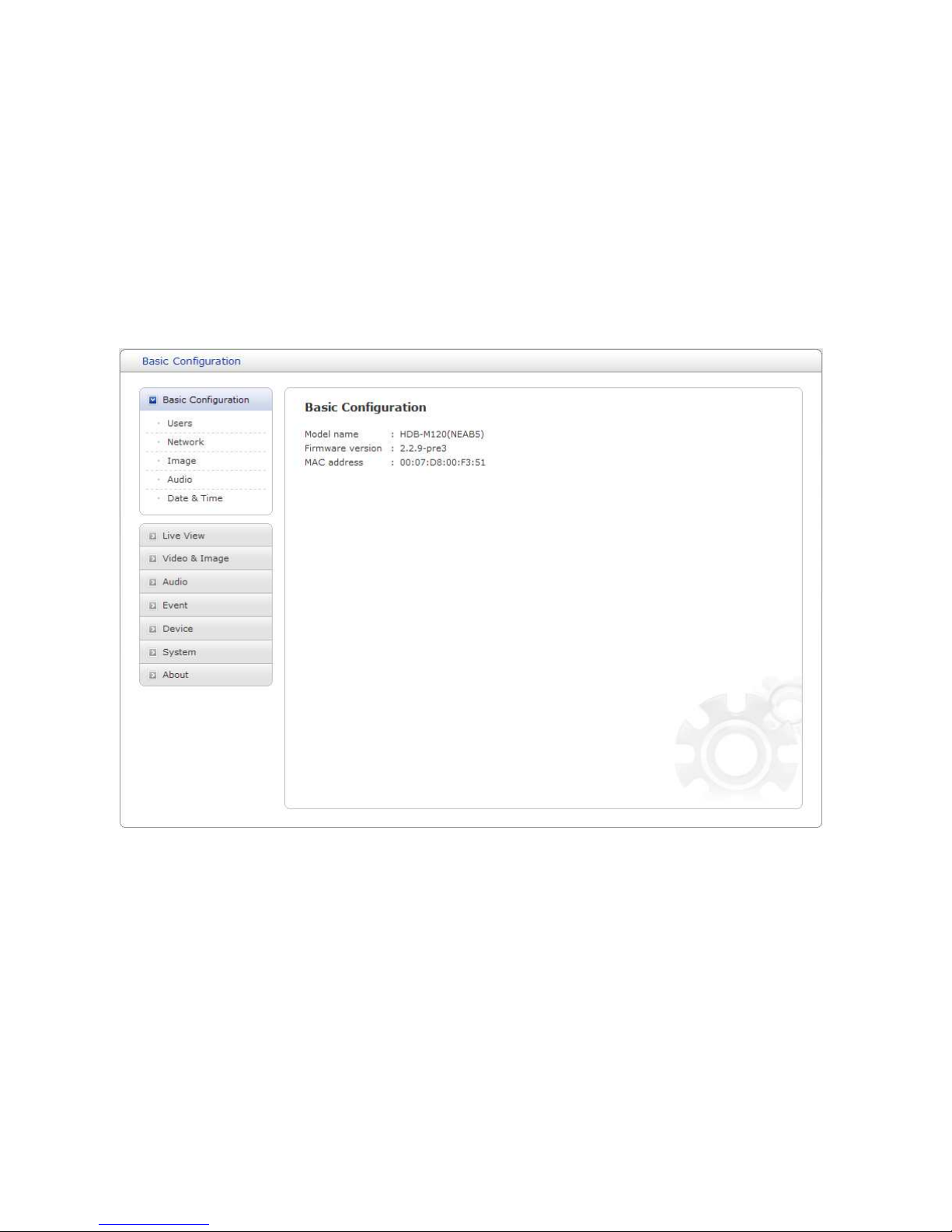
Basic Configuration
Use this section to set up the basic settings of the camera. It will allow the user to gain access to
the live image and audio.
Figure 9. Basic Configuration
NOTE
The setting menu might not be available if the user does not have the permission to access this
feature. To gain access to the image the only setting that is required to be set is the IP address,
found in the Network section.
VK2-1080BXDN manual V1.0
22
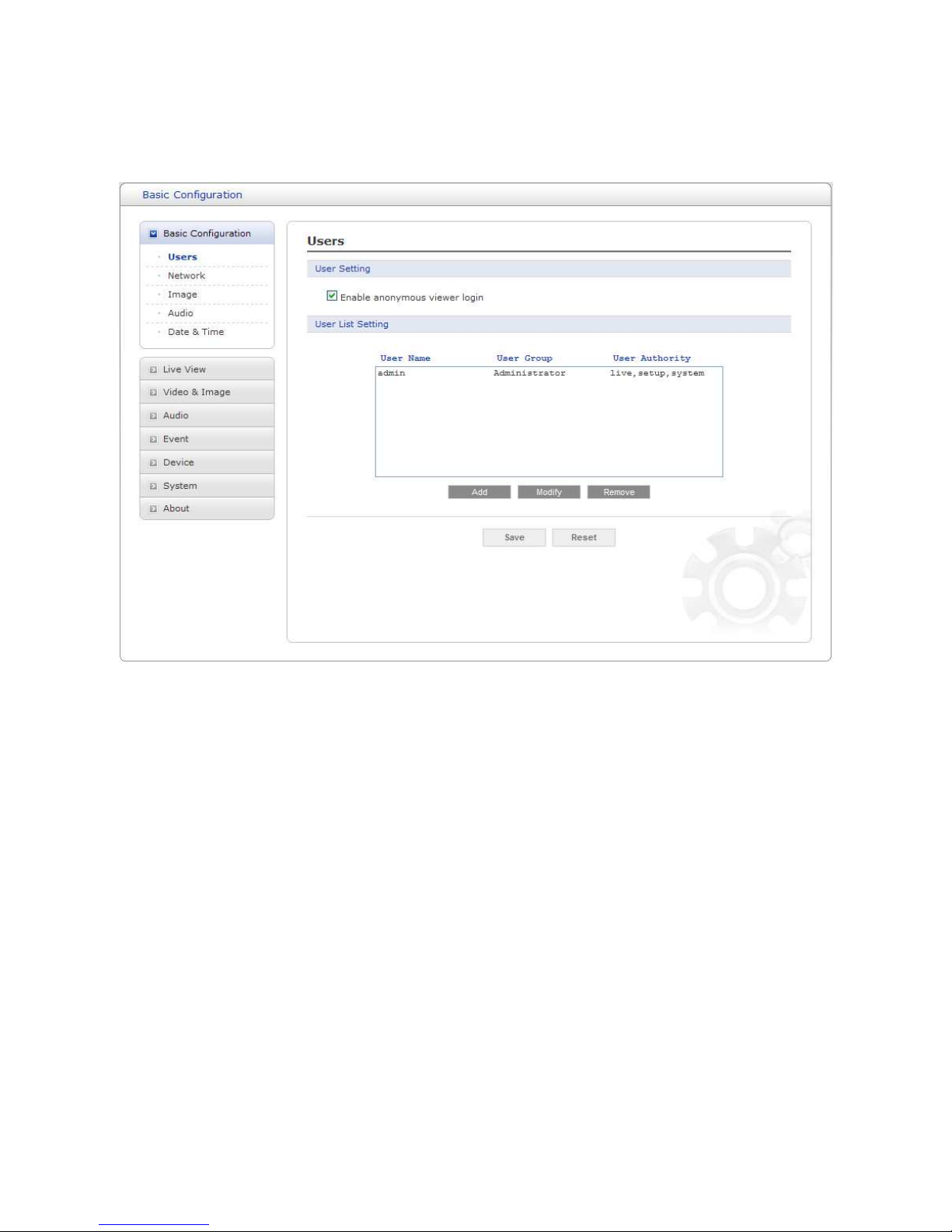
Users
Use the Users tab to manage user permissions for accessing the camera.
Figure 10. Basic Configuration / Users
User Setting: Click the Enable anonymous viewer login checkbox to enable anonymous user
login to the camera. This allows free access. The default setting is disabled.
User List Setting: User accounts can be added or modified or removed. The authority
depends upon user group automatically and shows the permission status to access the menus.
The default user name and password are
admin
.
User Name: Shows the name which registered to access the camera.
User Group: Shows the assigned permission given to users.
User Authority: Shows the permission status to access the menus.
- Click the Add, Modify, or Remove button for managing user account.
23
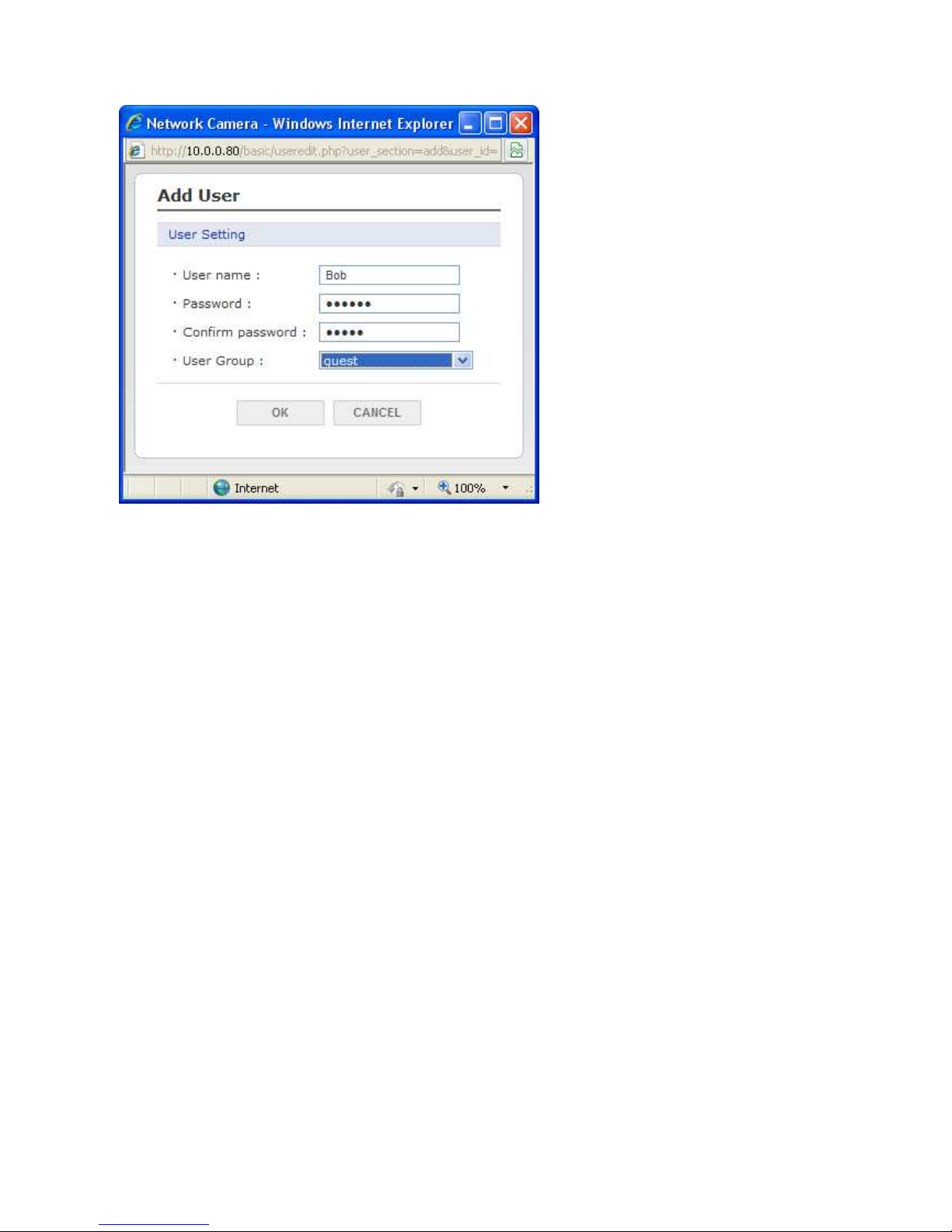
Figure 11. Basic Configuration / Users / Add User
To add a new user:
1. Click the Add button, new pop-up window above will appear.
2. Click in the User name box and type a new user name (1 to 14 alphanumeric characters). User
names are not case sensitive.
3. Click in the Password box and type a password (1 to 8 alphanumeric characters). Passwords are
case sensitive.
4. Click in the Confirm password box and retype a password.
5. Click in the User group box and select one of the groups you wish to assign to the user.
6. Click the OK button to save the settings and add a new user.
VK2-1080BXDN manual V1.0
24
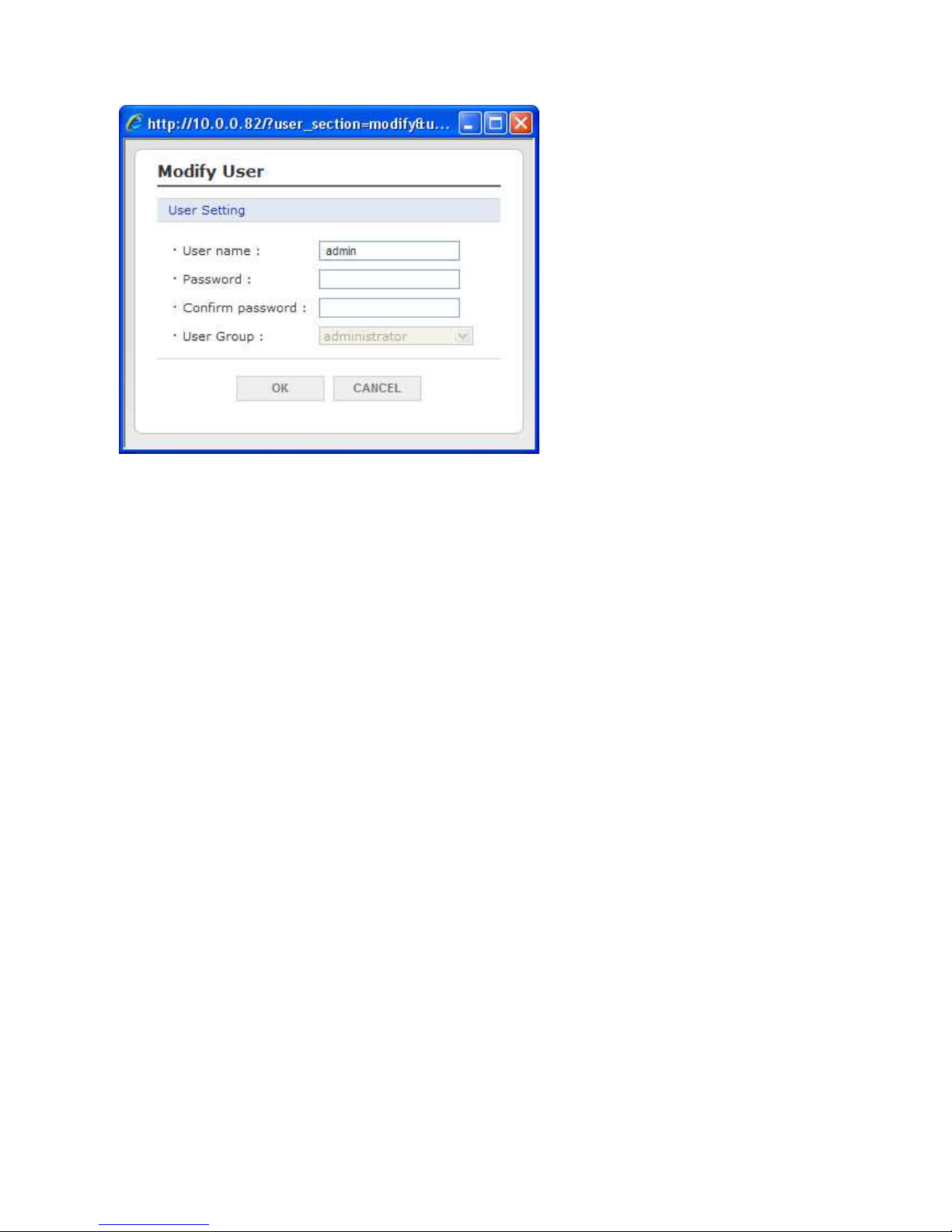
Figure 12. Basic Configuration / Users / Modify User
To modify a user:
1. Select The User name to be modified.
2. Click the Modify button, the new pop-up window appears.
3. Click in the Password box and type a password (1 to 8 alphanumeric characters). Passwords are
case sensitive.
4. Click in the Confirm password box and retype a password.
5. Click in the User group box and select one of the groups you wish to assign to the user.
6. Click the OK button to save the settings and modify a user.
NOTE
The user name can’t be modified.
To remove a user:
1. Select the user to be removed.
2. Click the Remove button. A dialog box appears with a confirmation message.
3. Click the OK button. The user profile is removed from the User List.
NOTE
The administrator can’t be removed.
- Click the Save button to save the settings, or click the Reset button to clear all of the information
you entered without saving it.
25
Network
Use the Network tab to manage basic network settings.
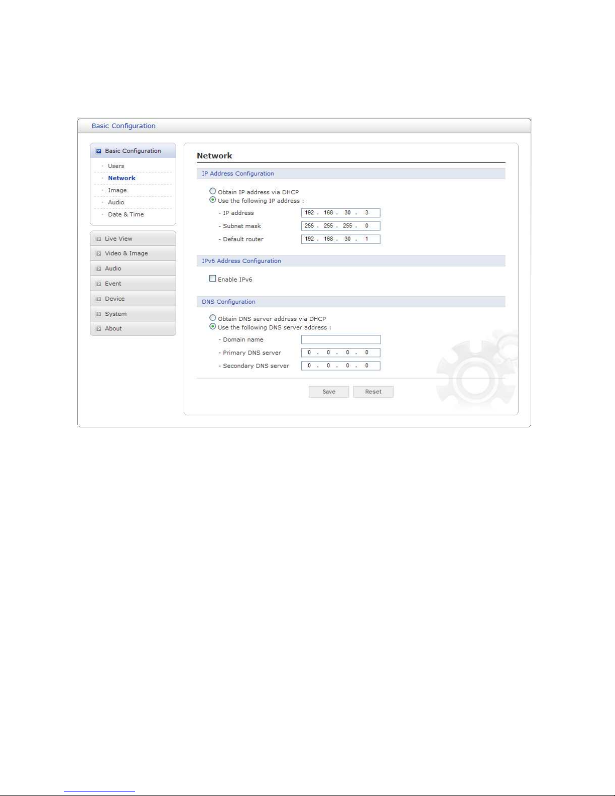
Figure 13. Basic Configuration / Network
IP Address Configuration: The DHCP (Dynamic Host Configuration Protocol)
automatically assigns an IP address to the device if there is a device on the network.
Obtain IP address via DHCP: Select this box if you want to assign the IP address from DHCP
server automatically, and then the remaining setting are read-only text.
Use the following IP address: Select this box if you want to assign the IP address manually.
IP address: The address of the camera connected to the network. Specify a unique IP address
for this network camera.
Subnet mask: The address that determines the IP network that the camera is connected to
(relative to its address). Specify the mask for the subnet the network camera is located on.
Default router: The router that accesses other networks. Specify the IP address of the default
router (Gateway) used for connecting devices attached to different networks and network segments.
IPv6 Address Configuration: Check this box to enable IPv6 address configuration.
Other settings for IPv6 are configured in the network router.

VK2-1080BXDN manual V1.0
26
DNS Configuration: DNS (Domain Name Service) provides the translation of host names to
IP addresses on your network.
Obtain DNS server via DHCP: Select this box if you want to use the DNS server settings
provided by the DHCP server automatically, and then the remaining setting are read-only text.
Use the following DNS server address: Select this box if you want to assign the DNS server
address manually
Domain name: Enter the domain name used by the network camera.
Primary DNS server: Enter the IP address of the primary DNS server.
Secondary DNS server: Enter the IP address of the secondary DNS server.
- Click the Save button to save the settings, or click the Reset button to clear all of the information
you entered without saving it.
27
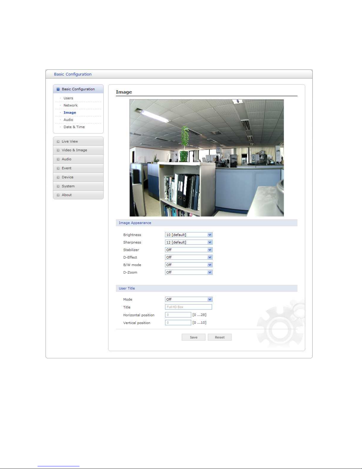
Image
Use the Image tab to adjust the camera image settings.
Figure 14. Basic Configuration / Image

VK2-1080BXDN manual V1.0
28
Image Appearance:
Brightness: The image brightness can be adjusted in the range 0-20, where a higher value
produces a brighter image. The default setting is 10.
Sharpness: Controls the clarity of detail in a scene. The sharpness can be adjusted in the range
0-17. If you set the sharpness value to higher, the image outline becomes sharper. If you set a
lower value, the image outline becomes less sharp. The default setting is 12.
Stabilizer: The image stabilizer function minimizes the appearance of shaky images caused by
low-frequency vibration. This function is useful for outdoor surveillance. If you set the Stabilizer to
ON, the Digital zoom is set to [x1.1] automatically.
D-Effect (Digital-Effect):
-- OFF: Turn off the digital effect.
-- MIRROR: Turn on the mirror effect.
-- ROTATE: Rotate the picture (180°).
-- V-FLIP: Flip the picture vertically.
B/W mode (Black/White mode):
-- OFF: Display the picture in color.
-- ON: Display the picture in gray scale.
D-Zoom (Digital-Zoom):
1. Select D-Zoom to ON and click the Save button. A D-Zoom OSD windows will be appears and the
Digital zoom is set to [x1.1] automatically.
2. Use up arrow or down arrow to select an option then use left or right Direction button to select a
level.
-- ZOOM: Use [Left Direction] or [Right Direction] button to zoom in or out.
-- PAN: Use [Left Direction] or [Right Direction] button to move the screen (left or right).
-- TILT: Use [Left Direction] or [Right Direction] button to move the screen (up or down).
User Title: The camera image can be titled
Mode:
-- OFF: No title is displayed
-- ON: A title can be entered and amended
Title: Type a camera title, which can not be more than 20 characters.
Horizontal position: The horizontal position can be adjusted in the range 0-28, where a higher
value moves the title further to the right. The default setting is 0.
Vertical position: The vertical position can be adjusted in the range 0-10, where a higher value
moves the title further down the screen. The default setting is 0.
- Click the Save button to save the settings, or click the Reset button to clear all of the information
you entered without saving it.
29
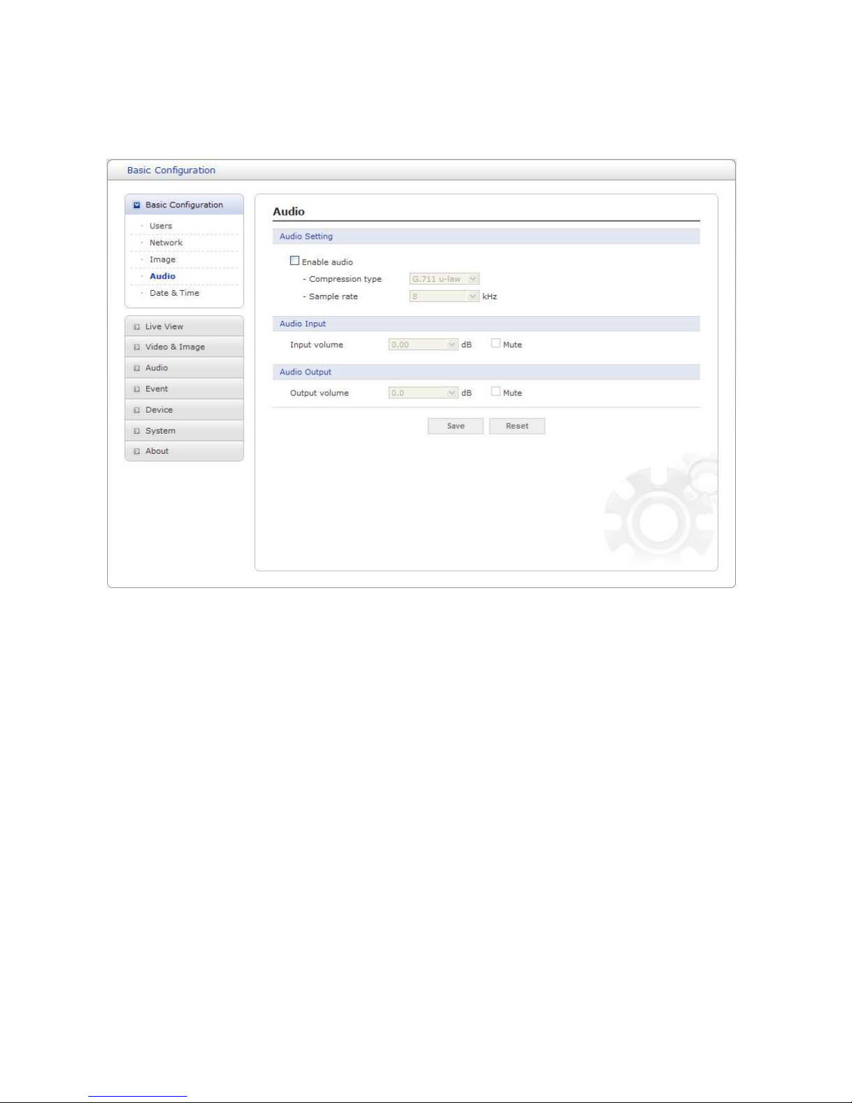
Audio
Use the Audio tab to manage the basic audio settings for the camera.
Figure 15. Basic Configuration / Audio
Audio Setting: Click the Enable audio checkbox to enable audio. This page describes how to
configure the basic audio settings for the camera. This camera supports bi-directional full duplex
audio.
Compression type: G.711 is the international standard for encoding wired-telephone audio on
64kBit/s channel. It is a PCM (Pulse Code Modulation) scheme operating at 8 kHz sample rate. The
default setting is G.711 µ-law.
Sample rate: Indicates the number of times per second the sound is sampled. The default
setting is 8 kHz.
NOTE
G.711, also known as Pulse Code Modulation (PCM), is a very commonly used waveform codec.
G.711 uses a sampling rate of 8,000 samples per second, with the tolerance on that rate 50 parts
per million (ppm). Non-uniform quantization (logarithmic) with 8 bits is used to represent each
sample, resulting in a 64 kbit/s bit rate. There are two slightly different versions; μ-law, which is
used primarily in North America, and A-law, which is in use in most other countries outside North
America. G.711 μ-law tends to give more resolution to higher range signals while G.711 A-law
provides more quantization levels at lower signal levels.

VK2-1080BXDN manual V1.0
30
Audio Input:
Input volume: The Input volume can be adjusted in the range from -21.00 to 21.00 dB. The
default setting is 0 dB. Click the Mute box if you do not want the audio input.
Audio Output:
Output volume: The Output volume can be adjusted in the range from -18.1 to 6.0 dB. The
default setting is 0 dB. Click the Mute box if you do not want the audio output.
- Click the Save button to save the settings, or click the Reset button to clear all of the information
you entered without saving it.
 Loading...