

Viotech ACD-3VM501 User Manual
User Manual
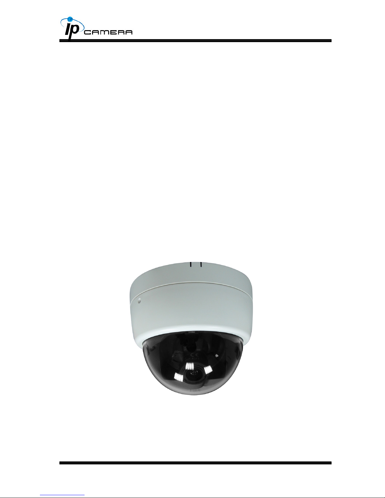
3-AXIS INDOOR DOME
IP CAMERA
2
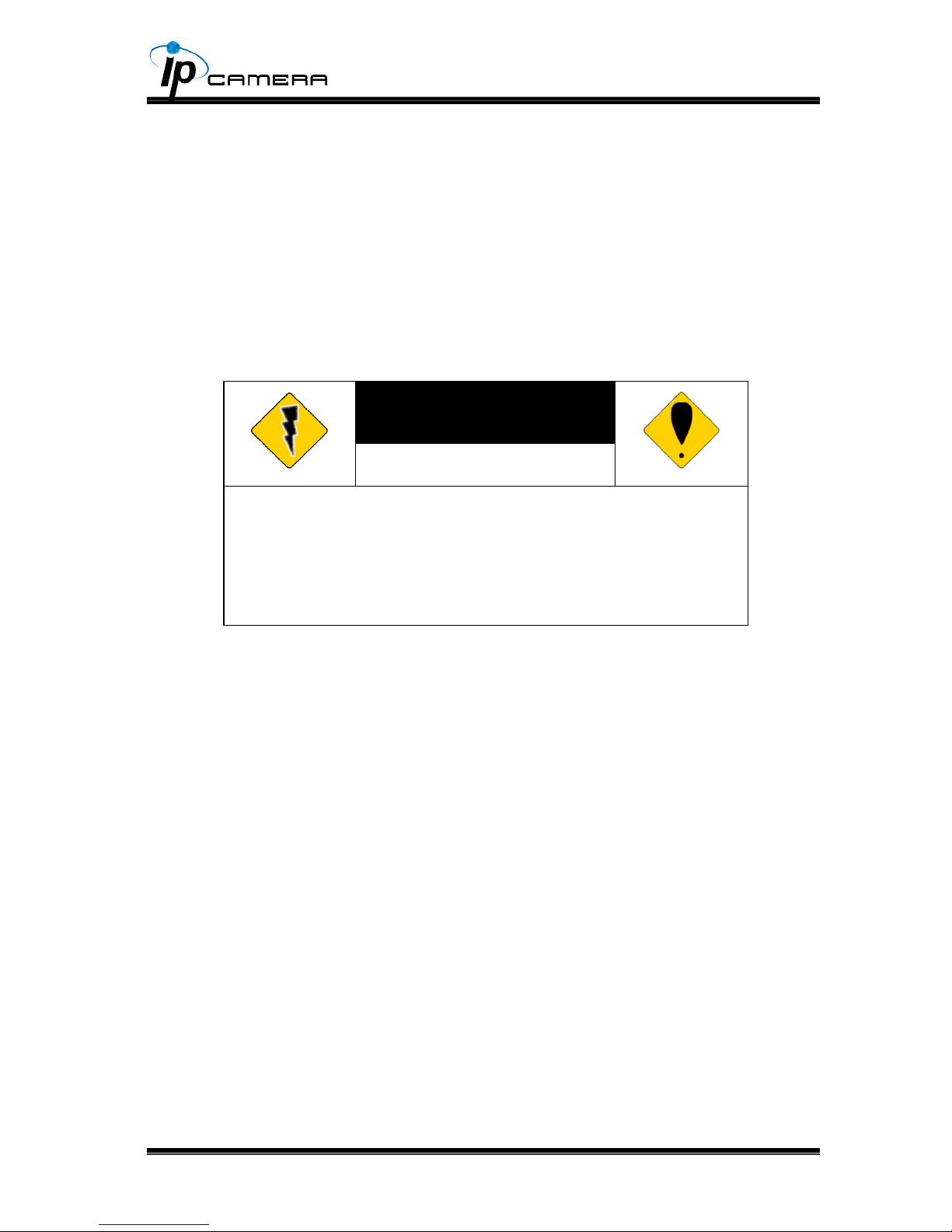
WARNINGS
TO REDUCE THE RISK OF FIRE OR ELECTRIC SHOCK, DO NOT EXPOSE THIS
PRODUCT TO RAIN OR MOISTURE.
DO NOT INSERT ANY METALLIC OBJECT THROUGH VENTILATION GRILLS.
CAUTION
CAUTION
DO NOT CHANGE THE LENS
CAUTION: THIS CAMERA DESIGN IS BASED ON THE
INCLUDED LENS. LENS REPLACEMENT MAY CAUSE
INSTABILITY OF IMAGE QUALITY.
PLEASE REFER SERVICING TO QUALIFIED SERVICE
PERSONNEL.
COPYRIGHT
THE TRADEMARKS MENTIONED IN THE MANUAL ARE LEGALLY REGISTERED
TO THEIR RESPECTIVE COMPANIES.

CONTENT
V1.0_120712
Preface I. 4
Product Specications II. 4
Product Installation III. 6
Monitor Setting A. 6
Hardware Installation B. 7
IP Assignment C. 9
Install ActiveX control D. 11
Live Video IV. 13
IP Camera Conguration V. 15
System A. 16
Network B. 20
A/V Setting C. 28
Event List D. 34
Network Conguration VI. 41
I/O Conguration VII. 43
Factory Default VIII. 45
Package Contents IX. 46
SD Card Compatibility X. 47
4
PrefaceI.
This IP Camera is a 2-Megapixel 3-Axis IP camera with the web server
built in. User can view real-time video via IE browser. IP Camera supports
simultaneously H.264, Motion JPEG & MPEG4 video compression and dual
streaming which provides smooth and high video quality. The video can be
stored in the SD card and played back remotely. With user friendly interface, it is
an easy-to-use IP camera which is designed for security application.
Product SpecicationsII.
Main Features:
High Denition Resolution at 30FPS support(720P)•
Video output•
2M-Pixel CMOS Sensor•
Power over Ethernet available•
IR LED Built-in 12M•
Mechanism IR cut Filter•
H.264/ JPEG/ MPEG4 compression•
SD card backup•
2-way audio•
Support Cell Phone/PDA/3GPP•
SDK for Software Integration•
Free Bundle 36 ch recording software•
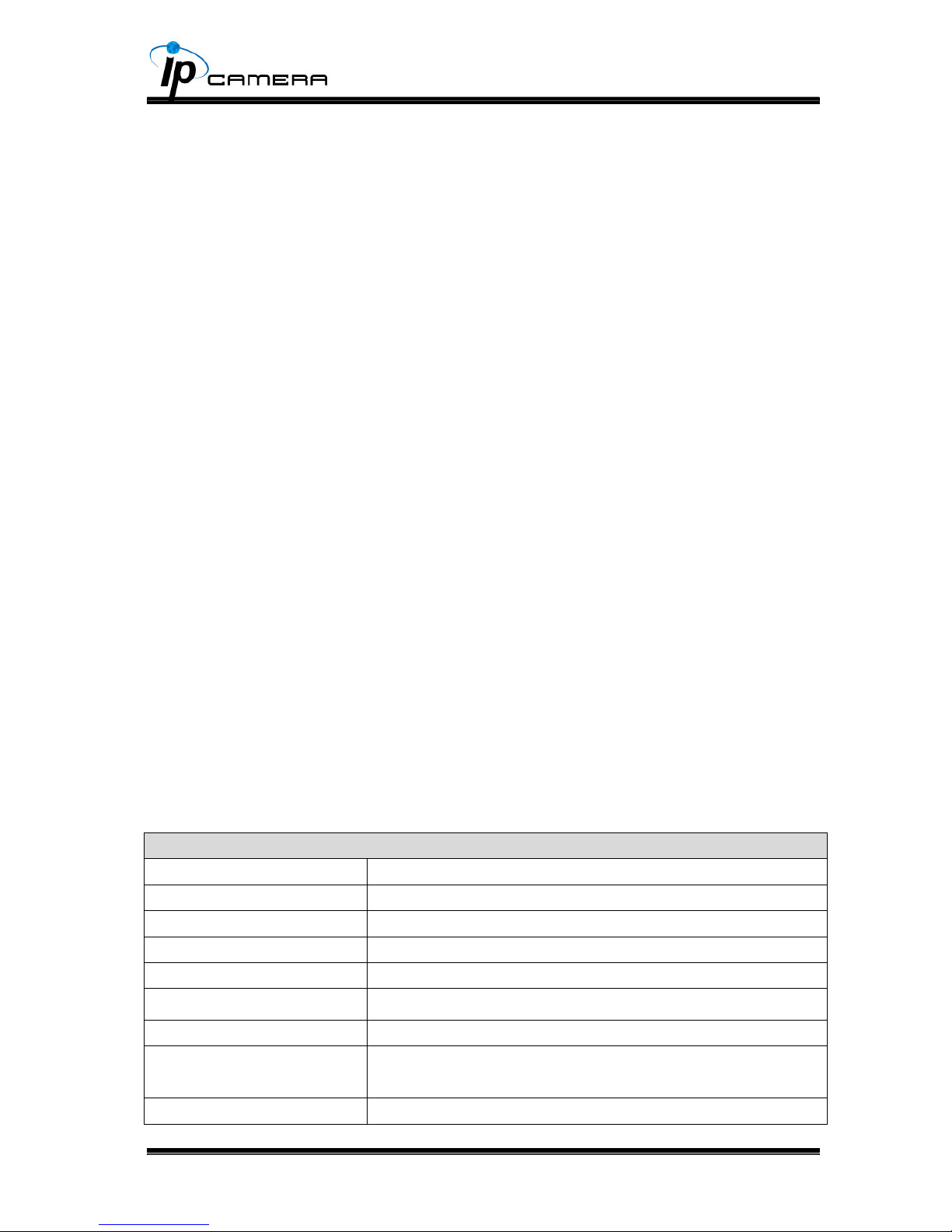
HLC-1NAD Specications
Hardware
CPU ARM 9,32 bit RISC
RAM 256MB
Flash 16M
Image sensor 1/3” CMOS (2M-Pixel)
Support DC Iris Yes
Lens Type Vari-focal 2.7~9mm Mega Pixel Lens
ICR Mechanism IR Cut Filter(optional)
LED Built-in 18 IR LED (optional)
IR Distance-12M (Optional)
I/O 1in/1 relay out
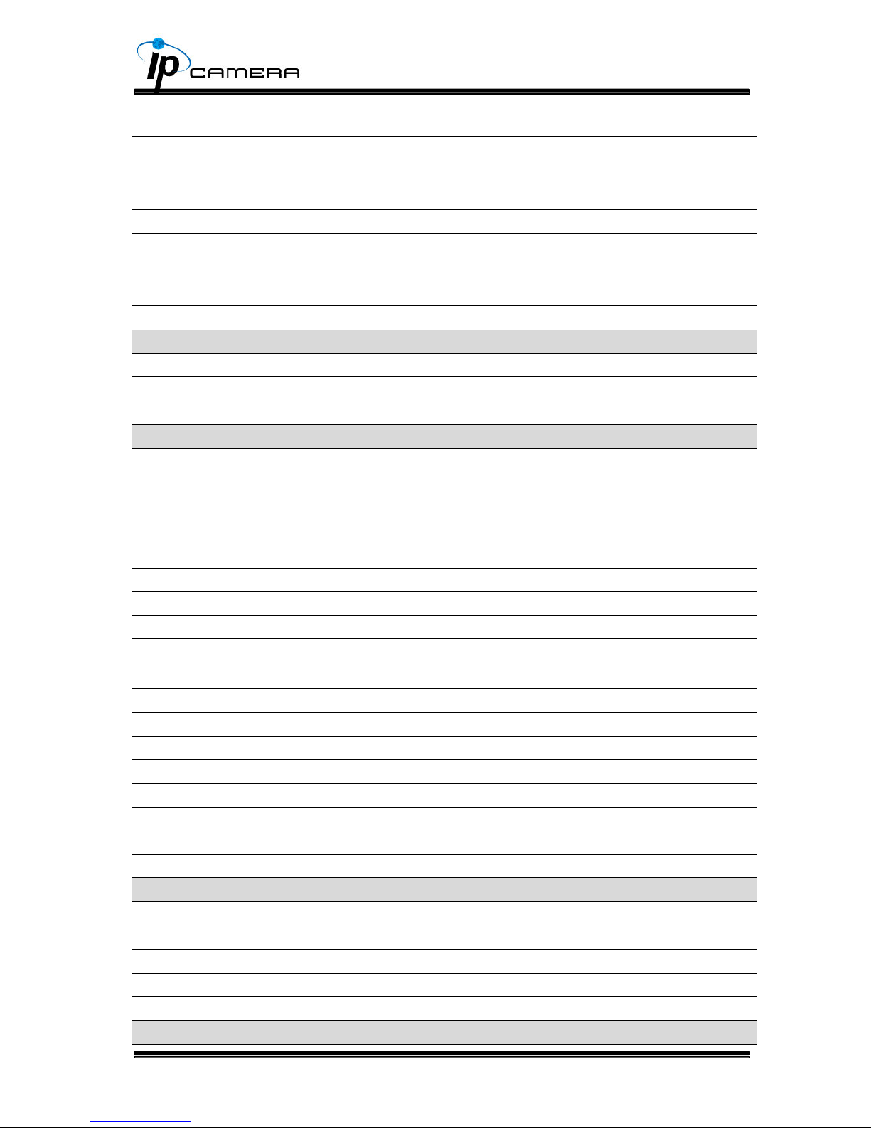
5
Video Out x1
Audio in x1
Audio Out x1
Power Over Ethernet Yes (optional)
Power Consumption DC 12V 470mA
3-Axis Gimbal Adjustments
Angle
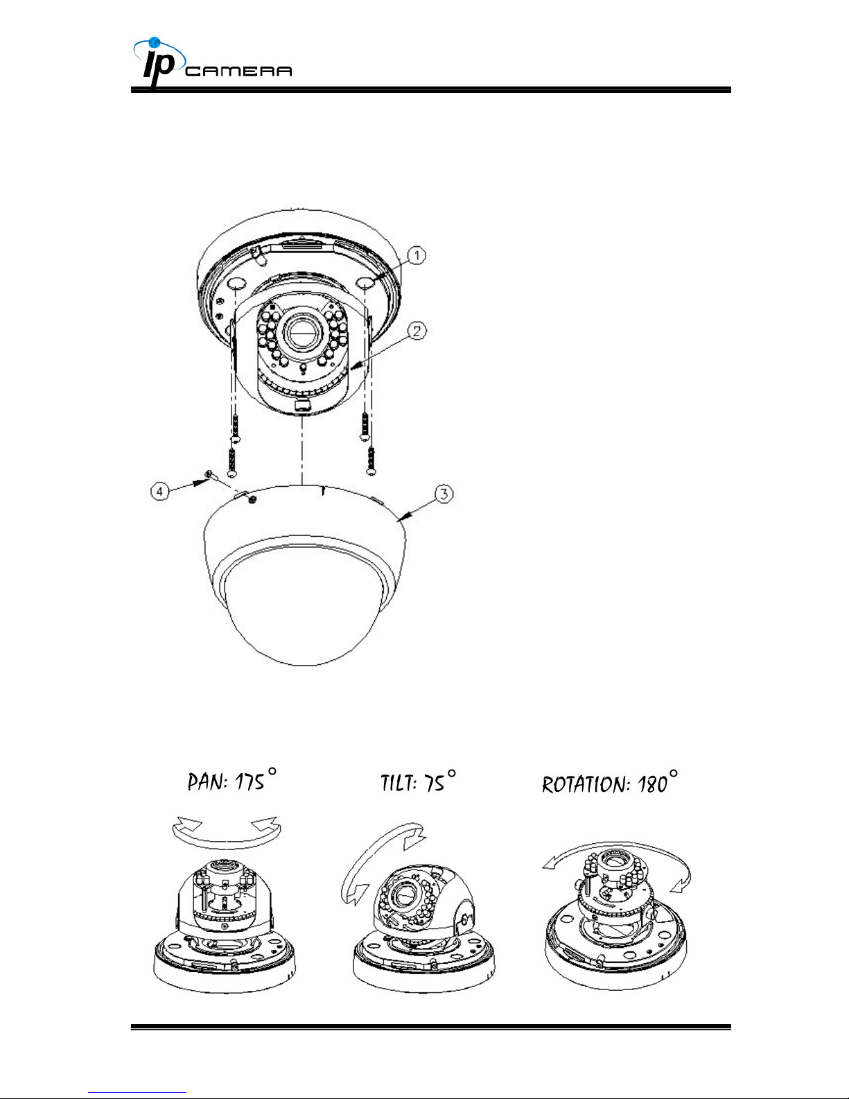
Pan: 175
∘
Tilt: 75
∘
Rotation: 180
∘
Dimensions
∮
132 * H 108.4
Network
Ethernet 10/ 100 Base-T
Network Protocol HTTP, TCP/ IP, UDP, SMTP, FTP, PPPoE, DHCP, DDNS,
NTP, UPnP, 3GPP
System
Video Resolution 1600x1200,1280x1024, 1280x960, 1280x720, 800x600,
640x480, 320x240, 160x120
CMOS setting Brightness, Contrast, Sharpness, AGC, BLC, AWB
R-Gain/B-Gain, Flip, Mirror, Night Mode, Day/Night
Adjustable
Triple Streaming Yes
Image snapshot Yes
Full screen monitoring Yes
Privacy Mask Yes, 3 different areas
Compression format H.264/ JPEG/ MPEG4 (3GPP only)
Video bitrate adjust CBR, VBR
Motion Detection Yes, 3 different areas
Triggered action Mail, FTP, Save to SD card, Relay, Samba
Pre/ Post alarm Yes, congurable
Security Password protection
Firmware upgrade HTTP mode, can be upgraded remotely
Simultaneous connection Up to 10
Audio Yes, 2-way(Duplex Support)
SD card management
Recording trigger Motion Detection, IP check, Network Status (wire
Connection only), Schedule, Alarm
Video format AVI, JPEG
Video playback Yes
Delete les Yes
Client System requirement
6
OS Windows 7, 2000, XP, 2003, Microsoft IE 6.0 or above
Hardware Suggested Intel Dual Core 1.66G,RAM: 1024MB, Graphic card:
128MB
Minimum Intel-C 2.8G, RAM: 512MB, Graphic card: 64MB
*SPECIFICATIONS ARE SUBJECT TO CHANGE WITHOUT NOTICE.
Product InstallationIII.
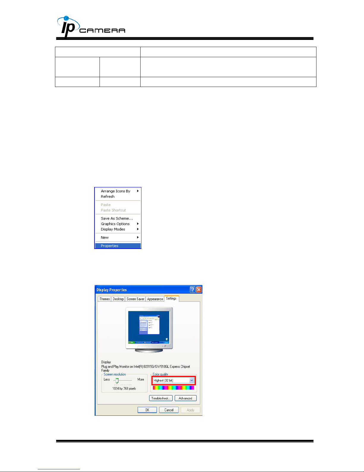
Monitor SettingA.
Right-Click on the desktop. Select “ Properties”1.
Change color quality to highest (32bit).2.
7
Hardware InstallationB.
Dome Installation Steps1.
3-Axis Diagram2.
Use the 3-Axis bracket to adjust the camera to appropriate angle.
Use screws to lock the a.
bottom of camera to the
ceiling or the wall.
Use 3-Axis to adjust the b.
lens angle.
Close the dome cover.c.
Tighten the screw on the d.
cover to x it.
8
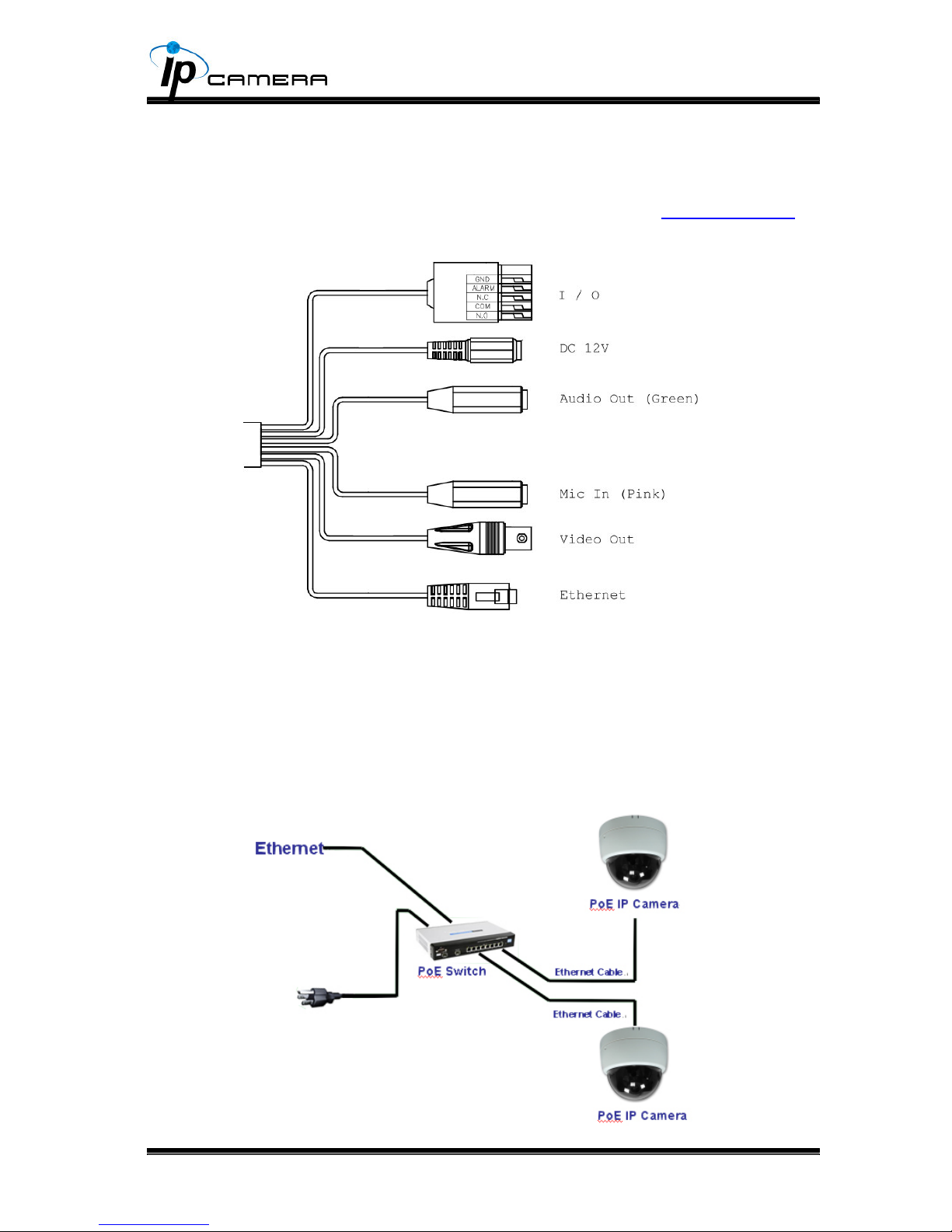
Connector Instruction3.
Connect power adaptor, then connect the IP camera to PC or network. Set
up the network congurations according to the network environment. About I/
O setting, please refer to chapter VII in User Manual: "I/O Conguration" for
detail.
PoE ( Power Over Ethernet)(Optional) 4.
802.3at, 30.0W PoE Switch is recommended
Power over Ethernet (PoE) is a technology that integrates power into a
standard LAN infrastructure. It enables power to be provided to the network
device, such as an IP phone or a network camera, using the same cable as
that used for network connection. It eliminates the need for power outlets at
the camera locations and enables easier application of uninterruptible power
supplies (UPS) to ensure 24 hours a day, 7 days a week operation.
9
IP AssignmentC.
You can use the software“IP Installer” to assign the IP address of IP Camera. 1.
The software is in the attached CD.
There are two language versions of IP installer. Choose one as your need: 2.
IPInstallerCht.exe: Chinese version
IPInstallerEng.exe: English version
There are 3 kinds of IP conguration.3.
Fixed IP (Public IP or Virtual IP)a.
DHCP (Dynamic IP)b.
Dial-up (PPPoE)c.
Execute IP Installer4.
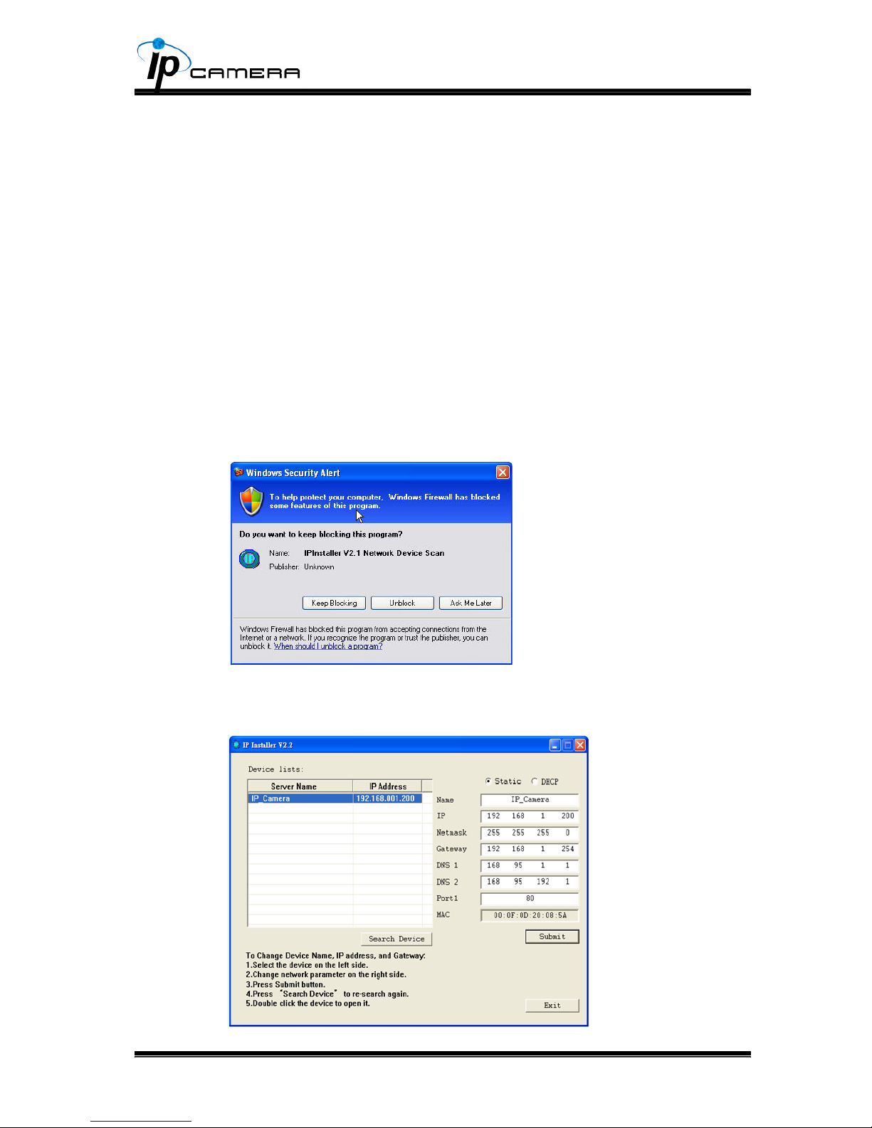
For Windows XP SP2 user, the following message box may pop up. Please 5.
click “Unblock”.
IP Installer conguration:6.
10
IP Installer will search for all IP Cameras connected on Lan. Click “Search 7.
Device” to refresh the result list.
Click one of the IP Camera listed on the left side. The network conguration 8.
of this IP camera shows on the right side. You may change the “name” of the
IP Camera as your preference (eg: Ofce, warehouse). Change the parameter
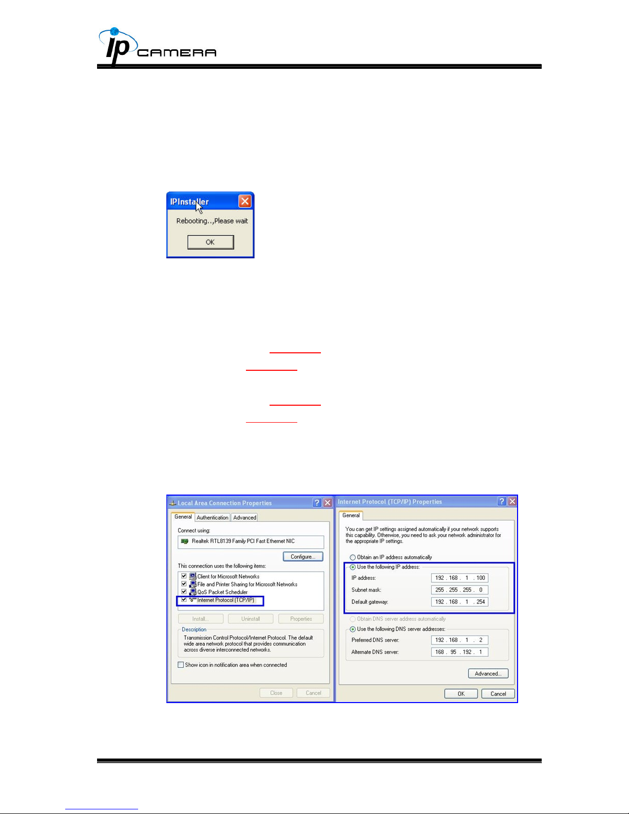
and click “Submit” . It will apply the change and reboot the Device.
Please make sure that the IP address of your PC and IP Camera are on the 9.
same subnet.
The same Subnet:
IP CAM IP address: 192.168.1.200
PC IP address: 192.168.1.100
Different Subnets:
IP CAM IP address: 192.168.2.200
PC IP address: 192.168.1.100
To Change PC IP address:
Control Panel→Network Connections→ Local Area Connection Properties→
Internet Protocol (TCP/IP) → Properties
A quick way to access remote monitoring is to double-click the selected IP 10.
Camera listed on “Device list” of IP Installer. An IE browser will be opened.
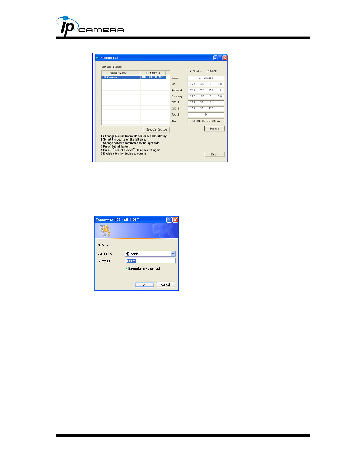
11
If you link to the IP Camera successgully, there pops a box asking you to log 11.
in. Please key in the default user name"admin" and password"admin" when
you link to the IP Camera for the rst time. You can revise the user name and
password later. Please refer to Chapter V: "A.2. User Management".
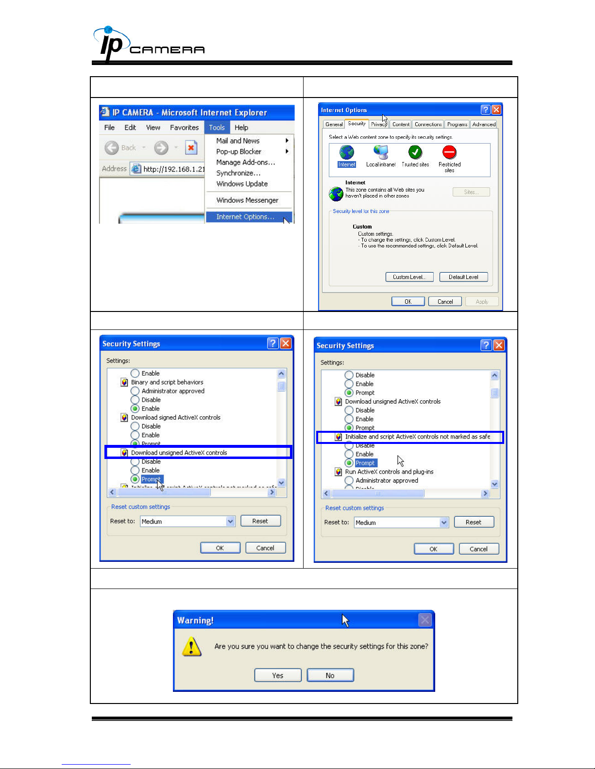
Install ActiveX controlD.
For the rst time to view the camera video via IE, it will ask you to install the
ActiveX component.
If the installation failed, please check the security setting for the IE browser.
IE→Tools → Internet Options… → Security Tab → Custom Level… → 1.
Security Settings → Download unsigned ActiveX controls→ Select “Enable”
or Prompt.
IE → Tools → Internet Options… → Security Tab → Custom Level… 2.
→Initialize and script ActiveX controls not marked as safe → Select “Enable”
or Prompt.
12
1 2
3 4
5
When popup the following dialogue box, click “Yes”.
13
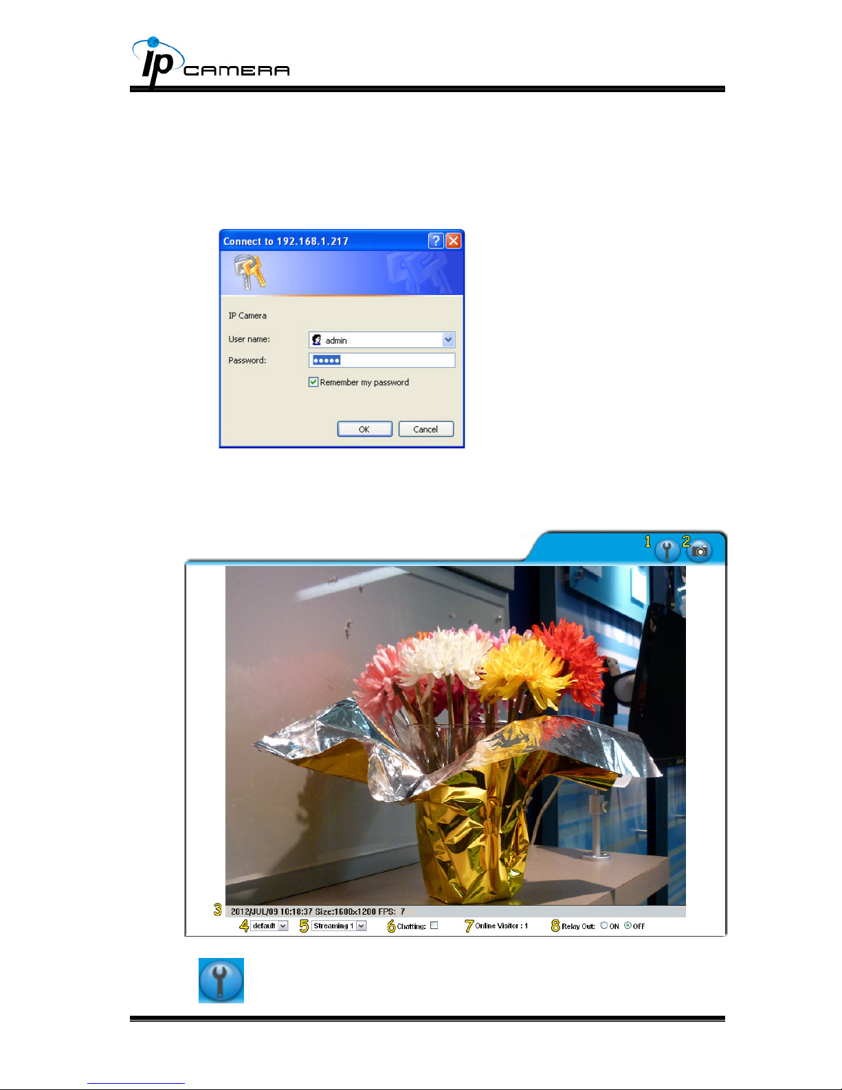
Live VideoIV.
Start an IE browser, type the IP address of the IP camera in the address eld.
It will show the following dialogue box. Key-in the user name and password. The
default user name and password are “admin” and “admin”.
When the IP Camera is connected successfully, it shows the following
program interface.
1. : Get into the administration page
14
2. : Video Snapshot
Show system time, video resolution, and video refreshing rate3.
Adjust image, 1/2x, 1x, 2x4.
Select video streaming source 5. (If in”Video Setting” the streaming 2 setting is
closed, this option will not appear here.)
IP Camera supports 2-way audio. Click the “Chatting” check box, then you 6.
can use microphone connected to the PC to talk to the Camera side.
Show how many people connect to this IP camera.7.
Tick the Relay out "ON" box to trigger the relay output for testing. Tick "Off" to 8.
stop triggering.
Double-click the video to switch to full screen view. Press “Esc” or double-click
the video again back to normal mode.
Right-Click the mouse on the video, it will show a pop-up menu.
Snapshot: Save a JPEG picture1.
Record Start: Record the video in the local PC. It will ask you where to save 2.
the video. To stop recording, right-click the mouse again. Select “Record
Stop”. The video format is AVI. Use Microsoft Media Player to play the
recorded le.
Mute: Turn off the audio. Click again to turn on it. 3.
The "mute" botton does not affect the playback recording video. As long as
the "IP Camera to PC" option in the audio setting is enabled, all the audio will
be recorded into the playback video even you click "mute" in the live page.
Full Screen: Full-screen mode.4.
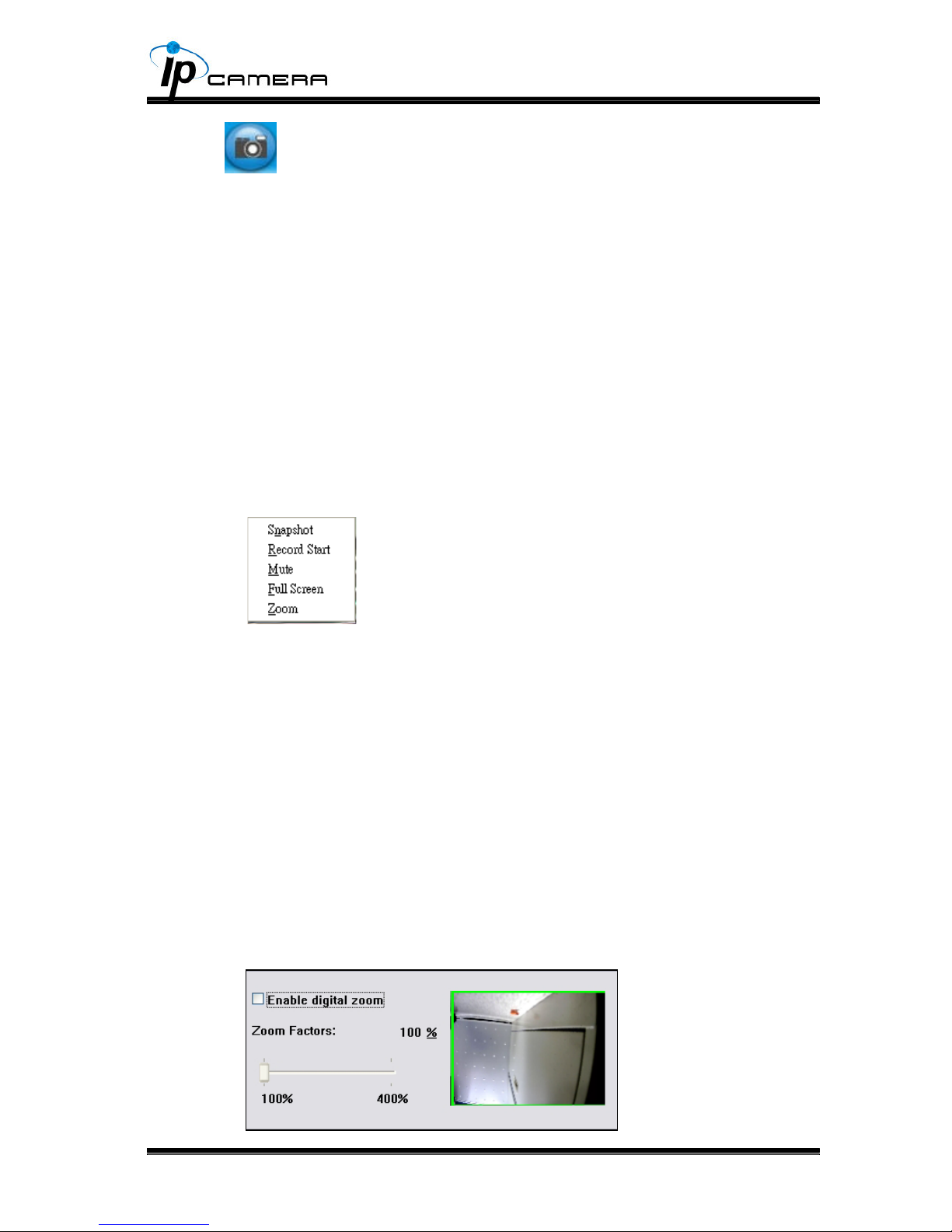
ZOOM: Enable zoom-in and zoom-out functions. Select “Enable digital zoom” 5.
option rst within the pop-up dialogue box and then drag and drop the bar to
adjust the zoom factors.

15
IP Camera CongurationV.
Click
to get into the administration page as below.
Click
to back to the live video page.
 Loading...