

Vionet GAS COUNTER SERIES, VIOGR24T, VIOGR24, VIOGR36, VIOGR36T Installation & Operation Manual
...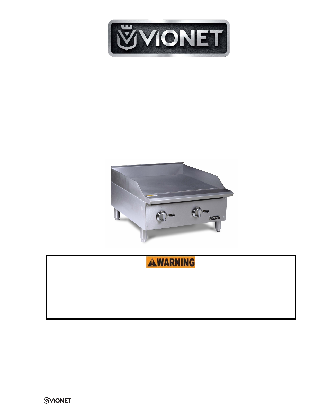
Commercial Cooking Equipment
INSTALLATION & OPERATION MANUAL
GAS COUNTER SERIES
GRIDDLES
This manual contains important information regarding your VIONET unit. Please
read the manual thoroughly prior to equipment
Failure to comply with regular maintenance guidelines out-lined in the manual may
void the warranty. Improper installation, adjustment, alteration, service or
maintenance can cause property damage, injury or death. Read this manual
thoroughly before installing or servicing this equipment.
MUST READ!
1
Owner’s/Installer Manual Rev 1E
As continued product improvement is a policy of Vionet, specifications are subject to change.
8830 Siempre Viva Road Suite 100 | San Diego CA 92154 | https://www.vionetequipment.com
set-up, and operation maintenance.
SAFETY PRECAUTIONS
the operator smells gas. Obtain the instructions from the local gas supplier
Before installing and operating this equipment, be sure everyone involved in its operation is fully trained
and aware of precautions. Accidents and problems can be caused by failure to follow fundamental rules
and precautions.
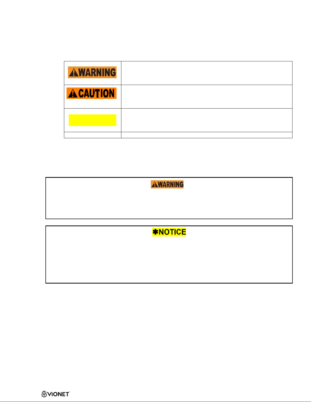
The following symbols, found throughout this manual, alert you to potentially dangerous conditions to
the operator, service personnel, or to the equipment.
This symbol refers to a potential hazard or unsafe practice that could result
in injury or death.
This symbol refers to a potential hazard or unsafe practice that could result
in injury, product damage, or property damage.
NOTICE
FOR YOUR SAFETY TO AVOID SERIOUS PERSONAL INJURY AND PROPERTY DAMAGE:
• ALWAYS install equipment in a work area with adequate light and space.
• ONLY operate on a solid, level, nonskid surface that is nonflammable and away from sinks and
water hazards.
• NEVER bypass, alter, or modify this equipment in any way from its original condition. Doing so
may create hazards and will void warranty.
Do not store or use gasoline or other flammable vapors and liquids in the vicinity of this or any other appliance.
Keep area around appliances free and clear of combustibles.
Purchaser of equipment must post in a prominent location, detailed instructions to be followed in the event
VIONET Griddles are intended for commercial use only. Not for household use.
Warranty will be void if service work is performed by other than an authorized technician, or if other than
genuine VIONET replacement parts are installed.
Be sure this Operator’s/Installer’s Manual and important papers are given to the proper authority to retain for
future reference.
This symbol refers to information that needs special attention or must be
fully understood, even though not dangerous.
FIRE HA
ZARD FOR YOUR SAFETY
Congratulations! You have purchased one of the finest pieces of commercial cooking equipment on the
market. You will find that your new equipment, like all VIONET equipment, has been designed and
manufactured to meet the toughes
engineered and designs are verified through laboratory tests and field installations. With proper care and field
maintenance, you will ex
carefully.
perience years of reliable, trouble-free operation. For
t standards in the industry. Each piece of VIONET equipment is carefully
RETAIN THIS MANUAL FOR FURTURE REFERECE
2
Owner’s/Installer Manual Rev 1E
As continued product improvement is a policy of Vionet, specifications are subject to change.
8830 Siempre Viva Road Suite 100 | San Diego CA 92154 | https://www.vionetequipment.com
best results, read this manual

Table of Contents
Specifications ---------------------------------------------------------------------------------------- Page 3
Installation -------------------------------------------------------------------------------------------- Page 5
Operation --------------------------------------------------------------------------------------------- Page 9
Seasoning -------------------------------------------------------------------------------------------- Page 10
Cleaning ---------------------------------------------------------------------------------------------- Page 10
Service/Trouble Shooting ------------------------------------------------------------------------- Page 12
Parts --------------------------------------------------------------------------------------------------- Page 13
Warranty ---------------------------------------------------------------------------------------------- Page 14
Read these instructions carefully before attempting installation. Installation and initial startup should be
performed by a qualified installer. Unless the installation instructions for this product are followed by a
qualified service technic i an (a per s on exper i enc ed in a nd k now le dge ab le with the insta lla tio n of c om mercial
gas and/or electric cooking equipment) then the terms and conditions on the Manuf ac tur er’s Limited
will be rendered void and no warranty of any kind shall apply.
Warranty
SPECIFICATIONS
GAS and GAS PRESSURE
This unit is factory supplied in L.P Gas. This unit can be converted to Natural gas by a
licensed and certified gas technician. Documentation may be necessary for warranty issues. Failure to comply
with this instruction will void warranty.
Unit ins
National Gas Installation Code, CSA-B149.1, or the Propane Installation Code, CSA-B149.2 as applicable
and in accordance with local codes.
The applianc
from the gas supply piping system during any pressure testing of that system at test pressures in excess of
1/2" P.S.I. (3.45kPa).
These model
Instruc
smells gas. Safety information can be obtained from your local gas supplier.
s are designed, built, and sold for commercial use only.
tions must be posted in a prominent location. All safety precautions must be taken in the event the user
tallation must conform to the National Fuel Gas Code, ANSI Z223.1/NFPA 54, the
e and it’s individual shutoff valve (to be supplied by user) must be disconnected
3
Owner’s/Installer Manual Rev 1E
As continued product improvement is a policy of Vionet, specifications are subject to change.
8830 Siempre Viva Road Suite 100 | San Diego CA 92154 | https://www.vionetequipment.com
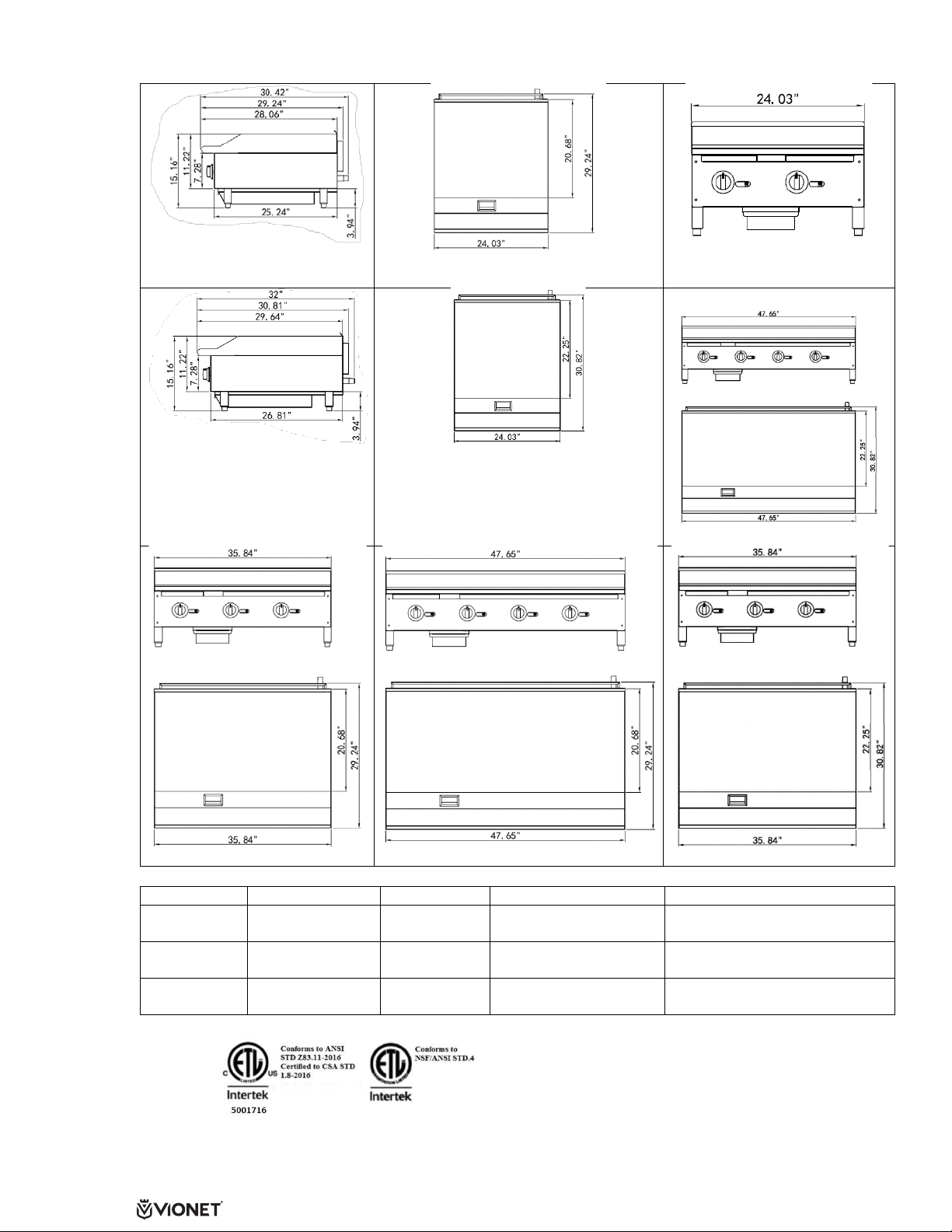
SPECIFICATIONS (Continued)
Griddle Front
48” Thermostat Griddle
36” Manual Griddle
36” Thermostat Griddle
Model
Description
BTU.hr
Number of Burners
Gas Type
Gas Griddle 24”
60,000
2
Natural Gas or Propane*
Gas Griddle 36”
90,000
3
Natural Gas or Propane*
Gas Griddle 48”
120,000
4
Natural Gas or Propane*
Use for all Manual Griddles
Use for a Therm
ostat Griddles
24” Manual Gri
24” Thermostat G
ddle Top
riddle Top
24” Manual & Thermostat
VIOGR24
VIOGR24T
VIOGR36-
VIOGR36T
VIOGR48
VIOGR48T
*Shipped setup for L.P. Gas and includes a kit for conversion to Natural Gas
As continued product improvement is a policy of Vionet, specifications are subject to change.
48” Manual Griddl
e
4
Owner’s/Installer Manual Rev 1E
8830 Siempre Viva Road Suite 100 | San Diego CA 92154 | https://www.vionetequipment.com
UNPACKING
and water solution before operating the unit.
Unpack the Griddle immediately after receipt. Remove the Gas Griddle from the crate; remove all packaging
on and surrounding the unit and be certain to remove all protective plastics and residues from all surfaces.
Make sure that all parts provided are located. Equipment must have the legs properly installed before use.
Before using this equipment it must be cleaned and dried thoroughly.
INSTALLATION
NOTE: it is vital that the purchaser of this equipment post in a prominent location instructions to be followed in
the event that the user smells gas. This information shall be obtained by consulting the local gas supplier. The
purchaser of this equipment must post in a prominent location.
1. Read this manual thoroughly before installation and operation. DO NOT proceed with installation and
operation if you have any questions or do not understand anything in this manual. Contact your local
representative or VIONET first.
2. Select a location for the Griddle that has a level, solid, nonskid surface that is nonflammable and away
ater hazards or sinks, and is in a well-lighted work area away from children and visitors.
from w
3. This equipment but be installed under a proper ventilation as required by local code.
Local codes regarding installation and ventilation vary greatly by area. The National Fire
Protection Association states in its NFPA 96 latest edition (see NFPA page at the beginning of
this manual) that local codes are “authority having jurisdiction” when it comes to
requirements for installation of equipment. Therefore, installation should comply with all local
codes.
4. Screw legs into (A) the permanently fastened nuts on the four corners of the unit and tighten by hand.
Legs must be installed to adequately provide proper ventilation to the unit.
5. Level unit by adjusting the four feet and tighten securely. The adjustable feet have an adjustment of
one inch. Do not slide unit with legs mounted. Lift if necessary to move unit.
6. The supplied gas pressure regulator is factory set at 4” Natural Gas W.C. or 10” Propane Gas.
7. THESE UNITS ARE SUITABLE FOR INSTALLATION ON NON-COMBUSTIBLE SURFACE ONLY.
Noncombustible clearances: 6” sides (152 mm), 6” rear (152 mm), 4” floor (102 mm).
8. Do not obstruct the flow of combustion and ventilation air under the unit by the legs or behind the unit
by the flue. Do not place objects between the bottom of the unit and the counter top.
9. There must be adequate clearance for removal of the front panel. All major parts except the burners
are removable through the front if the gas is disconnected.
10. It may be necessary to adjust the balance of gas volume and air supply to each burner. This must be
done by and authorized service technician.
11. Pipe threading compound must be resistant to the action of liquefied petroleum gas. DO NOT USE
TEFLON TAPE.
DO NOT use an open flame to check for leaks. Check all gas piping for leaks with a soap
The installation of this appliance must conform to local codes, or In the absence of local codes, the
National Fuel Gas Code, ANSI Z223.1/NFPA 54, or the Natural Gas and Propane Installation Code, CSA
B149.1, as applicable.
• The appliance and its individual shut off valve must be disconnected from the gas supply piping
system during any pressure testing of that system at test pressures in excess of ½ PSI (3.5kPa).
• The appliance must be isolated from the gas supply piping system by closing its individual manual
shut off valve during any pressure testing of the gas supply piping system at test pressures equal to
less than ½ PSI (3.5kPa).
As continued product improvement is a policy of Vionet, specifications are subject to change.
8830 Siempre Viva Road Suite 100 | San Diego CA 92154 | https://www.vionetequipment.com
5
Owner’s/Installer Manual Rev 1E

Clearance and positioning around the appliance: This appliance must be installed adjacent to noncombustible surfaces only with a minimum spacing of six (6” inches from all sides. This appliance must be a
minimum distance of six (6” inches from another appliance. The appliance must have the supplied four (4”
inch legs installed and be placed on a non-combustible surface.
Air supply and ventilation: The area in front and around the appliances must be kept clear to avoid any
obstruction of the flow of combustion and ventilation air. Adequate clearance must be maintained at all times
in front and at the sides of the appliance for servicing and proper ventilation.
Pressure Regulator: All commercial cooking equipment must have a pressure regulator on the incoming
service line for safe and efficient operation. The regulator provided for this appliance is adaptable for both
Natural Gas and Liquefied Propane (LP) Gas.
Regulator information: ¾” NPT (National Pipe Thread) inlet and outlet; factory adjusted for ten (10”) inch
Water Column (WC) LP Gas standard and may be converted by qualified personnel to be used for Natural
Fas at four (4”) Water Column pres
Prior to connecting the regulator, check
maximum pres
the regulator prov
direction, and should point downstream to the appliance.
sure of ½ PSI (14” WC). If the line pressure is beyond this limit, a step down regulator before
ided will be required. The arrow forged into the bottom of the regulator body shows gas flow
sure.
the incoming line pressure. The regulator can only withstand a
Gas Conversion: Conversion from LP Gas to
Natural or vice versa may only be performed by
the factory or its authorized service agent. In the
case of troubleshooting, endure that the correct
orifice sizes of the spuds have been provided.
Natural Gas Orifice: #36dms(Thermostatic)/#37
dms(Manual)
Liquefied Propane (LP) Orifice
dms( Both Thermostatic and Manual)
NOTE: The orifice size is marked on the spud.
Gas Connection: The appliance comes fitted with a ¾” NPT (National Pipe Thread) male adapter for
connection to the pressure regulator.
Maintenance: A qualified service company should check the unit for safe and efficient operation on an annual
basis. Contact the factory representative or local service company to perform maintenance and repairs.
Gas Piping: Gas piping shall be of such size and so installed as to provide a supply of gas sufficient to meet
the full gas input of the appliance. If the appliance is to be connected to existing piping, it shall be checked to
determine if it has adequate capacity. Joint compound (pipe dope) shall be used sparingly and only on the
male threads of the pipe joints. Such compounds must be resistant to the action of Liquefied Propane (LP)
gases.
#51
Any loose dirt or metal particles, which are allowed to enter the gas lines on this appliance,
will damage the valve and affect its operation. When installing this appliance, all pipe and fittings must be
free from any internal contaminates. It is recommended that a “drip leg” be installed in-line before the
regulator.
Manual Shut Off Valve: A manual shut off valve should be installed upstream from the manifold, within four
(4) feet, (1.2M) of the appliance and in a position where it can be reached in the event of an emergency.
6
Owner’s/Installer Manual Rev 1E
As continued product improvement is a policy of Vionet, specifications are subject to change.
8830 Siempre Viva Road Suite 100 | San Diego CA 92154 | https://www.vionetequipment.com

Checking For Gas Leaks: Using a gas leak detector or a soapy water solution is recommended for locating
gas leaks. Matches, candle flame, or other sources of ignition shall not be used for this purpose. Check entire
piping system for leaks.
Exhaust Canopy: Cooking appliances inherently create a good deal of heat and smoke and should be
installed under an efficient exhaust hood with flame proof filters. A vertical distance of not less than four (4)
feet shall be provided between the top of the appliance and filters or any other combustible material.
FIRE DEATH HAZARD If you smell gas follow the instruction provided by the gas supplier.
Do not touch any electrical switch; do not try to light the burner; do not use a telephone within close
proximity.
Lighting the Pilot: The manifold units are equipped with a standing pilots and each should be lit immediately
after the gas is supplied to the appliance.
1. Before attempting to light pilots, turn off the main gas valve to the appliance and wait five (5) minutes
to clear the gas.
2. Turn off all gas control knobs (E). See figure 1.
3. Turn on main gas valve and light all pilots.
4. The pilot burner must be lit at the end of the tube. Hold an ignition source through the pilot light hole
(D) in the front panel at the pilot tube. When the flame is established remove ignition source.
5. To shut down the appliance, turn off the main gas valve to the appliance.
NOTE: Smoke appearing on initial use of the appliance is normal. This is a result of the rust preventative
coating burning off. This will occur for at least fifteen (15) minutes during the first use or seasoning process.
Pilot Flame Regulation: The pilot flame on the appliance has been factory adjusted. When adjustment is
necessary, adjust the pilot flames as small as possible, but high enough to light the burner immediately when
burner valve is turned to the “HIGH” setting. Access to the pilot flame adjustment screw is obtained by
removing the front panel.
Burner Adjustment: Remove the front panel to gain access. Turn burner valve knob to “HIGH” position.
Slowly decrease mixing ring aperture to give a soft blue flame having luminous tips, then slowly increase
opening to a point where the yellow tips disappear and a hard blue flame is obtained.
COMMISSIONING: Commission of your new Griddle is of the utmost importance. Commissioning is the
thorough and methodical testing of the equipment, subsystems, and systems to ensure that the final product
functions properly and safely at the work site. By identifying any potential problems (i.e.: equipment location,
ventilation, local fire/electrical codes, installation, operator training, and certification) prior to equipment being
placed into service, costly outages and potential damages may be avoided.
ALWAYS SAFETY FIRST!
Improper installation, adjustment, alteration, service or maintenance can cause property
damage, injury or death. Read the installation, operating and maintenance instruction thoroughly before
installing or servicing this equipment.
FIRE HAZARD
Do not install or use without 4” legs. Use of this equipment without legs can cause the appliance to
overheat and cause a fire.
7
Owner’s/Installer Manual Rev 1E
As continued product improvement is a policy of Vionet, specifications are subject to change.
8830 Siempre Viva Road Suite 100 | San Diego CA 92154 | https://www.vionetequipment.com

FIRE, INJURY or DEATH HAZARD This appliance is for use in non-combustible
location only
FIRE, INJURY or DEATH HAZARD
This equipment mist be installed by a qualified installer in accordance with all federal, state and local
codes. Failure to install this equipment properly can result in injury or death.
FIRE and INJURY or DEATH HAZARD
Injuries or death can occur if this equipment is not used properly. To reduce risk of injury or death:
• Keep the appliance area free and clear from combustibles
• Do not obstruct the flow of combustion and ventilation air
• Do not spray controls or the outside of the appliance with liquids or cleaning agents
• Let hot appliance cool before cleaning or moving
• The appliance should only be used in a flat, level position
• Do not operate unattended
IMPORTANT SAFEGUARDS & SAFETY INSTRUCTIONS
When using gas cooking equipment, basic safety precautions should always be followed,
including the following:
The Griddle outside surfaces may become HOT after use. Use caution when touching the unit.
• Never directly touch the cooking surface while the Griddle is on.
• Always turn off the unit when not in use, servicing or adjusting any parts or attachments, and before
cleaning.
• Never leave the Griddle on overnight.
• Do not operate any equipment with a damaged or leaking gas line, ignitor or valve, or if the unit is
dropped or damaged in any manner. Call for Service.
• The use of attachments not recommended or sold by the manufacture may cause fire, injury or even
death.
• DO NOT US OUTDOORS.
• Do not use this equipment for any use other that the use intended by the manufacturer.
• Never use the Griddle as a heating source.
• The Griddle does not contain any user-serviceable parts. Dealer or recommended qualified
technicians should carry out repairs. Do not remove any components or service panels on this
product.
• Never bypass, alter, modify, or attach any unauthorized parts to this equipment. Doing so may create
a hazard and will void warranty.
• We take every care to ensure that all products are safe. Steel cutting procedures used to
manufacture these items result in sharp edges. These sharp edges are removed to the best of our
ability; however, we insist the operator take care when in contact with this piece of equipment.
• Always keep hands, hair, and clothing away from heating source.
• Allow the Griddle to cool down after use and before dismantling for cleaning; the unit will be too hot to
handle immediately after use.
• DO NOT USE ICE TO COOL DOWN THE GRIDDLE PLATE. This will cause the Griddle plate to
warp and render it unusable.
8
Owner’s/Installer Manual Rev 1E
As continued product improvement is a policy of Vionet, specifications are subject to change.
8830 Siempre Viva Road Suite 100 | San Diego CA 92154 | https://www.vionetequipment.com

OPERATING INSTRUCTIONS
Operating the Griddle – Pilot Lighting Instructions for MANUALLY & THERMOSTAT CONTROLLED
GRIDDLES
Before operating Griddle, it should be checked to see that is sitting level. Adjust the feet to level the Griddle.
Be sure the catch tray had been properly placed.
The pilot light on the appliance has been set at the factory. Each burner has a pilot light.
1. Make sure all knobs are in the “OFF” position.
2. The main gas valve should be “CLOSED/OFF” for five (5) minutes prior to lighting plots to clear any
existing gas. (Main gas valve is supplied by others.)
3. Turn “ON or OPEN” the main gas valve to the unit.
4. Light and hold an ignition source (match) at the pilots. When the flame is established, remove the
ignition source. Repeat this step for each burner as each burner has its own individual pilot. The pilot
can be reached through the holes in the front of the unit.
5. Turn each burner knob “ON”. If the burners do not ignite promptly, turn the knobs “OFF”. From the
opening in the front panel, use a screwdriver and turn the pilot valve screw counterclockwise, which
will increase the flame height and repeat step 4.
If the pilot flame appears large than necessary, turn it down and retest the burner ignition. The pilot
flame should be as small as possible but large enough to guarantee reliable ignition of the burners
when the knobs are turned to “ON”. In the holes located in the front panel are pilot valve adjustments.
Use a screwdriver to turn the valve to adjust the flame height to your desired level.
All burners are lit from constantly b
all that is required to put the unit in service.
Igniting the Burner
To ignite the burner, turn knob to the “ON” position, then back off to the desired flame level. The range of
adjustment is virtually infinite between “ON” and “OFF”. On the Thermostat controlled griddle, turn the knob to
the desired temperature and allow it to preheat for approximately fifteen (15) minutes. (*Be sure the griddle
plate has been properly season before attempting to cook). The space between the legs at the bottom admits
combustion air. DO NOT BLOCK THIS SPACE.
All burners are lit from a constantly burning pilots. Turning the valve to the desired flame height is all that is
required to put the unit in service. Or if thermostatically controlled, simply set to the desired temperature.
Do not permit fans to blow directly at the unit. Whenever possible, avoid open windows next to the unit’s sides
or back. Avoid wall type fans which create air cross-currents within a room.
It is also necessary that sufficient air should be allowed to enter the room to compensate for the amount of air
removed by any ventilation system. Otherwise, a subnormal atmospheric pressure will occur, affecting
operation and causing undesirable working conditions.
A properly designed and installed hood will act as the heart of the ventilation system for the room or area in
which the unit is installed, and will leave the unit independent of changing draft conditions.
NOTE: It may be necessary to adjust the balance of gas, volume, and air supply to each burner. This must be
done by an authorized service technician.
urning pilots. Turning the valve to the desired flame height is
9
Owner’s/Installer Manual Rev 1E
As continued product improvement is a policy of Vionet, specifications are subject to change.
8830 Siempre Viva Road Suite 100 | San Diego CA 92154 | https://www.vionetequipment.com

SEASONING THE GRIDDLE
Figure 1.
F
A
B
D
E
C
Be sure to start with a clean Griddle surface. Pour small amount of high quality cooking oil to the griddle plate
(about one ounce (30 cc) per square foot of surface. Spread the oil over the entire griddle surface with a clean
cloth to create a thin film. Turn on the griddle to the lowest flame height or the lowest setting on the dial if it is
a thermostatically controlled griddle, and allow to heat for approximately 30 minutes. As the griddle is heating
it will be necessary to spread the oil over the griddle surface to prevent it from drying. Repeat this process 2
to 3 times gradually increasing the flame height each time or increase the temperature by turning the dial up
100 degrees at a time, on the burner until the griddle has a slick, mirror-like surface. This process will take 1
½ to 2 hours.
Note:
Each time the griddle is cleaned with soap and WATER, the seasoning is removed and this process
must be repeated.
Note:
If the process occurs too fast the griddle surface may turn a light bluish tint in color. The tint does not
hurt the griddle surface. You should allow the surface to cool and start over.
OPERATI
Turn the burners on about 15-20 minutes before cooking for preheating. Set the knobs to the desired flame
height or temperature.
NOTE: On Manu
maintain temperature by increasing or decreasing the flame height as required.
Each va
If different temperature settings are to be used, adjoining areas should be set to progressively higher
temperatures using the lowest temperature on the outside burners. A uniform and systematic approach to the
loading of the unit will produce the most consistent product results.
NG THE GRIDDLE
ally Operated Griddles there is NO TEMPERATURE CONTROL, you, the operator must
lve controls the gas flow to the burner to bring that area of the griddle up to the desired temperature.
A. LEG. Supports the Equipment
B. ADJUSTABLE FEET. Used to adjust the
level of the equipment.
C. DRIP TRAY. A try that collect grease and
oil. This tray can be removed for cleaning
D. PILOT LIGHT ACCES HOLE. Allows
access to the pilot light.
E. GAS CONTROL KNOB. Used to set or
adjust the temperature of the grilling
surface, manual or thermostat.
F. GRIDDLE PLATE. Cooking Surface
CLEANING
• DO NOT use any abrasive or flammable cleaning fluids.
• DO NOT hose down, immerse, or pressure wash any part of the Griddle, excluding the catch tray.
• NEVER use a scrubber pad (on all exterior surfaces, except the griddle plate), steel wool or abrasive
INSTRUCTIONS
material, or cleaners containing chlorine, iodine and ammonia, or bromine chemicals as these will
deteriorate the stainless steel and shorten the life of the unit.
10
Owner’s/Installer Manual Rev 1E
As continued product improvement is a policy of Vionet, specifications are subject to change.
8830 Siempre Viva Road Suite 100 | San Diego CA 92154 | https://www.vionetequipment.com

CLEANING INSTRUCTIONS (Continued)
PART
REQUIRED ACTION
FREQUENCY
Use a clean cloth and a non-abrasive cleaner to clean the stainless steel
from the control knobs.
griddle plate to cool may damage the plate.
USE CAUTION WHEN REMOVING!
IF CLEANING ALL THE GRIDDLE’S SURFACES, THE MAIN GAS VALVE MUST BE SWITCHED
TO THE CLOSED POSITION. AFTER CLEANING, THE GAS LINE CAN BE SWITCHED BACK TO THE
OPEN POSITION. PLEASE FOLLOW THE LIGHTING INSTRUCTION IN THE MANUAL TO RELIGHT THE
GRIDDLE’S PILOTS AS NEEDED.
Recommended Cleaning
It takes very little time and effort to keep the Griddle attractive and performing at top efficiency. Wait until the
griddle is cool after the unit had been turned off. Please follow the cleaning steps below:
Body
Back and
Side
Splashes
Contro
Griddl
Plate
ls
e
body of the Griddle.
Wipe the polished areas with a soft cloth.
Thoroughly clean. Wipe with clean, warm medley soapy water then re-wipe
splashes with a damp cloth.
Unit should be turned off when not in use.
It is recommended that the unit be disconnected from the gas supply by
closing the main gas valve. Use a clean cloth to wipe any grease or debris
Clean surface with a grill pad or metal spatula.
• Clean
• Rub with the grain of the metal while the griddle is still warm. A mild
• Remove all soap and debris thoroughly; wipe with a clean, damp
• The plate should then be covered with a thin film of oil to prevent
• Clean stainless surfaces with
• After each “weekly” cleaning, the griddle must be seasoned again.
the griddle surface thoroughly. If necessary, use a griddle
stone or grill pad. (If a griddle stone is not used correctly it will
damage the Griddle surface).
soap may be used on the plate surface to help clean it.
cloth.
rusting.
a damp cloth and polish with a soft
dry cloth. To remove discoloration, use a nonabrasive cleaner.
If the griddle usage is very high, the “weekly” cleaning procedures
may be done more often than once a week. The use of ice on the
Daily
Daily
Daily
Daily
eekly
W
&
Catch Tray Once the unit has cooled, remove the catch tray and discard the waste,
grease, debris and crumbs.
CAUTION: If the catch tray is permitted to fill too high, grease/debris is
likely to accumulate under the unit.
This catch tray/drawer is removed by pulling forward.
As continued product improvement is a policy of Vionet, specifications are subject to change.
8830 Siempre Viva Road Suite 100 | San Diego CA 92154 | https://www.vionetequipment.com
Owner’s/Installer Manual Rev 1E
As Needed
11

TROUBLESHOOTING
Problem
Possible Cause
Solution
Main gas line is closed.
Open Valve
allowing excess gas to clear.
Quick di
the way.
Griddle n
Flame is too high or too low Adjustment knob is turned up or
Pilot light not staying lit. Flame is too low
Strong s
area.
ot lighting
mell of gas in cooking
Pilot li
Cause unknow
down
Pilot t
Main gas li
One or more
out and burner knob turned on.
sconnect not inserted all
ght is not lit.
n
ube clogged.
ne leak
of the pilot may be
Check quic
make sure it is fully inserted into
female coupling.
Ignite pi
Call for
Adjust flame with control knob.
Adjust pilot light flame height.
Replace pi
service.
Turn off main gas valve. DO NOT
LIGHT FLAME, ignite anything, or
turn/switch on anything electrical.
Call Fire department if needed
and call for service.
Check to see if burners and pilots
are lit. If not, turn off all burner
valves and main gas valve and
wait for excess gas to dissipate.
Reattempt to light pilots after
k disconnect and
lot light.
service.
lot tube. Call for
Cooking surface is heating up
slowly.
Gas type of unit needs to be
converted.
If problems persist and the assigned solution does not remedy the issue, please call for service.
As continued product improvement is a policy of Vionet, specifications are subject to change.
Carbon buildup on griddle
surface.
Cause unknow
Unit ships from the factory L.P.
gas. Conversion from L.P Gas to
Natural is possible for this unit.
n
Clean griddle surface.
Call for
Call for service. This is not
considered a warranty issue. Do
not attempt conversion on your
own.
service.
12
Owner’s/Installer Manual Rev 1E
8830 Siempre Viva Road Suite 100 | San Diego CA 92154 | https://www.vionetequipment.com

PARTS
Ref #
Part #
Description
Ref #
Part #
Description
1
GC10001
U-SHAPED BURNER
8
GC10008
ADJUSTABLE LEG
2
GC10002
FIXED PLATE (PILOT)
9
GC10009
ORIFICE
3
GC10003
PILOT
10
GC10010
KNOB
4
GC10004
GAS VALVE
11
GC10011
PILOT PIN
PILOT REGULATING
VALVE
GRIDDLE THERMOSTAT
DIAL
7
GC10007
DRIP PAN
*
GC10014
FRONT PANEL
*
GC10003.1
PILOT TUBING
*
GC10015
PRESSURE REGULATOR
NOTICE
INSTALLATION OF OTHER THAN GENUINE VIONET PARTS WILL VOID THE WARRANTY ON
THIS EQUIPMENT.
The serial plate is located on the inside, behind the front panel. Replacement parts may be ordered either
through a VIONET Authorized Parts Distributor or an VIONET Authorized Service Agency
When ordering parts, please supply the Model Number, Serial Number, Part Number, and Description.
5 GC10005
6 GC10006 GAS INLET PIPE * GC10013
*Griddle Thermostat and Dial are not shown.
As continued product improvement is a policy of Vionet, specifications are subject to change.
12 GC10012 GRIDDLE THERMOSTAT
13
Owner’s/Installer Manual Rev 1E
8830 Siempre Viva Road Suite 100 | San Diego CA 92154 | https://www.vionetequipment.com

Commercial Cooking Equipment
INSTALLATION & OPERATION MANUAL
GAS COUNTER SERIES GRIDDLES
A product with the VIONET name incorporates the best in durability and low maintenance. We
all recognize, however, that replacement parts and occasional professional service may be
necessary to extend the useful life of this unit. When service is needed, contact a VIONET
Authorized Service Agency, or your dealer. To avoid confusion, always refer to the Model Number,
Serial Number, and Type of your unit.
14
Owner’s/Installer Manual Rev 1E
As continued product improvement is a policy of Vionet, specifications are subject to change.
8830 Siempre Viva Road Suite 100 | San Diego CA 92154 | https://www.vionetequipment.com
 Loading...