

Page 1
V
iolin
MEMORY
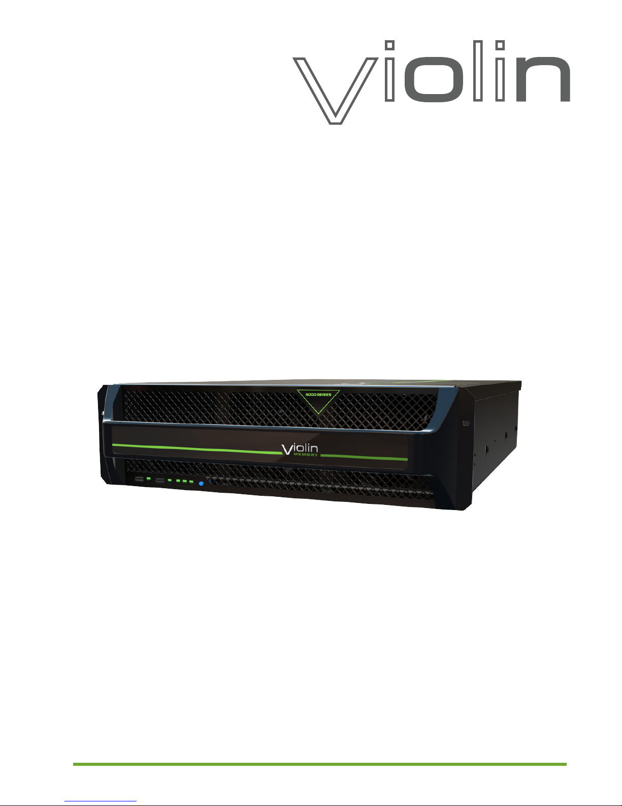
Violin 6000 Series
Memory Array Installation Guide
For Release V6.0.0
Document Number: 535-0045-00 Rev 02
May 2013
Page 2

LEGAL NOTICE
Copyright © 2010-2013 Violin Memory, Inc. All rights reserved.
Violin Memory, Violin Technologies, Violin, vSHARE, vCACHE, Flash Forward, and Violin and Design are trademarks,
registered trademarks or service marks of Violin Memory, Inc. (“Violin”) in the United States and other countries.
All other brands, product names, company names, trademarks, and service marks are the properties of their respective
owners.
This document and the associated software product are protected by copyright and international treaties, and are
distributed under license from Violin, including restrictions on their use, copying, redistribution and reverse engineering.
Unless otherwise agreed by Violin in writing, Violin’s standard end user license agreement shall apply, which may be
reviewed at www.violin-memory.com/legal. No part of this document may be reproduced, adapted or translated without
prior written permission of Violin, except as permitted under applicable copyright law. The associated software product may
include, access or otherwise operate, interface or be delivered with third party software or other applications or copyrighted
materials, which are copyrighted and licensed by Violin suppliers. Such third party materials and licenses are identified in
this document and/or at www.violin-memory.com/legal.
Violin assumes no responsibility for any typographical, technical or other error or omission in this document. Violin reserves
the right to periodically change the information contained in this document, but Violin makes no commitment to provide any
such changes, updates, enhancements or other additions in a timely manner or at all.
The only warranties for Violin products and services are set forth in the express warranty statements accompanying such
products and services. Nothing herein should be construed as constituting an additional warranty. THIS DOCUMENT
(INCLUDING ANY EXAMPLES AND OTHER INFORMATION CONTAINED HEREIN) IS MADE AVAILABLE “AS IS”
WITHOUT REPRESENTATION OR WARRANTY OF ANY KIND. VIOLIN MAKES NO REPRESENTATION OR
WARRANTY IN THIS DOCUMENT REGARDING ANY ASSOCIATED SOFTWARE OR ANY OTHER VIOLIN OR THIRD
PARTY HARDWARE, SOFTWARE OR OTHER PRODUCTS OR SERVICES REFERENCED HEREIN. TO THE FULLEST
EXTENT PERMITTED BY LAW, VIOLIN (FOR ITSELF AND ITS LICENSORS AND OTHER THIRD PARTIES IDENTIFIED
HEREIN) HEREBY DISCLAIMS ALL REPRESENTATIONS AND WARRANTIES, WHETHER EXPRESS OR IMPLIED,
ORAL OR WRITTEN, WITH RESPECT TO THE FOREGOING, INCLUDING WITHOUT LIMITATION, ALL IMPLIED
WARRANTIES OF TITLE, NON-INFRINGEMENT, QUIET ENJOYMENT, ACCURACY, INTEGRATION,
MERCHANTABILITY OR FITNESS FOR ANY PARTICULAR PURPOSE.
IN NO EVENT SHALL VIOLIN (OR ITS LICENSORS OR ANY OTHER THIRD PARTY IDENTIFIED HEREIN) BE LIABLE
CONCERNING ANY USE OF THIS DOCUMENT, REGARDLESS OF THE FORM OF ANY CLAIM OR ACTION
(WHETHER IN CONTRACT, NEGLIGENCE, STRICT LIABILITY OR OTHERWISE), FOR ANY DIRECT, INDIRECT,
PUNITIVE, INCIDENTAL, RELIANCE, SPECIAL, EXEMPLARY OR CONSEQUENTIAL DAMAGES, INCLUDING
WITHOUT LIMITATION, ANY LOSS OF DATA, LOSS OR INTERRUPTION OF USE, COST OF PROCURING
SUBSTITUTE TECHNOLOGIES, GOODS OR SERVICES, OR LOSS OF BUSINESS, REVENUES, PROFITS OR
GOODWILL, EVEN IF ADVISED OF THE POSSIBILITY OF SUCH DAMAGES.
Violin Memory, Inc.
685 Clyde Avenue
Mountain View, CA 94043
USA
ii
Violin 6000 Series Memory Array Installation Guide
535-0045-00 Rev 02
Page 3

Table of Contents
Preface . . . . . . . . . . . . . . . . . . . . . . . . . . . . . . . . . . . . . . . . . . . . . . . . . . . . . . . . . . . . . . . . . . . . . . . . . . . . . . . 1
CHAPTER 1. Memory Array Hardware Installation . . . . . . . . . . . . . . . . . . . . . . . . . . . . . . . . . . . . . . . . . . 5
Installation and Configuration Overview . . . . . . . . . . . . . . . . . . . . . . . . . . . . . . . . . . . . . . . . . . . . . . . . 5
Unpacking the Memory Array . . . . . . . . . . . . . . . . . . . . . . . . . . . . . . . . . . . . . . . . . . . . . . . . . . . . . . . . 7
Parts and Accessory List. . . . . . . . . . . . . . . . . . . . . . . . . . . . . . . . . . . . . . . . . . . . . . . . . . . . . . . . . . . . . . . . . .8
Installation Tools and Equipment . . . . . . . . . . . . . . . . . . . . . . . . . . . . . . . . . . . . . . . . . . . . . . . . . . . . . . . . . . .8
Standard System Configurations . . . . . . . . . . . . . . . . . . . . . . . . . . . . . . . . . . . . . . . . . . . . . . . . . . . . . 9
SAN-attached Storage Configurations . . . . . . . . . . . . . . . . . . . . . . . . . . . . . . . . . . . . . . . . . . . . . . . . . . . . . . .9
Direct-attached Storage Configurations . . . . . . . . . . . . . . . . . . . . . . . . . . . . . . . . . . . . . . . . . . . . . . . . . . . . . 11
Installing the Memory Array . . . . . . . . . . . . . . . . . . . . . . . . . . . . . . . . . . . . . . . . . . . . . . . . . . . . . . . . 14
Managing Thermal Heat Impact Within the Equipment Rack . . . . . . . . . . . . . . . . . . . . . . . . . . . . . . . . . . . . .14
Installing the Slide Rails . . . . . . . . . . . . . . . . . . . . . . . . . . . . . . . . . . . . . . . . . . . . . . . . . . . . . . . . . . . . . . . . .15
Installing the Cage Nuts . . . . . . . . . . . . . . . . . . . . . . . . . . . . . . . . . . . . . . . . . . . . . . . . . . . . . . . . . . . . . . . . .18
Attaching the Rack Ears (Optional). . . . . . . . . . . . . . . . . . . . . . . . . . . . . . . . . . . . . . . . . . . . . . . . . . . . . . . . .18
Mounting the Memory Array in the Equipment Rack. . . . . . . . . . . . . . . . . . . . . . . . . . . . . . . . . . . . . . . . . . . .19
Connecting the Cable Management Arm . . . . . . . . . . . . . . . . . . . . . . . . . . . . . . . . . . . . . . . . . . . . . . . . . . . .19
Grounding the Memory Array . . . . . . . . . . . . . . . . . . . . . . . . . . . . . . . . . . . . . . . . . . . . . . . . . . . . . . . . . . . . .20
Connecting AC Power Cords to the System . . . . . . . . . . . . . . . . . . . . . . . . . . . . . . . . . . . . . . . . . . . . . . . . . .21
Powering up the Memory Array . . . . . . . . . . . . . . . . . . . . . . . . . . . . . . . . . . . . . . . . . . . . . . . . . . . . . . . . . . .22
Connecting the Memory Array to a Host or Network . . . . . . . . . . . . . . . . . . . . . . . . . . . . . . . . . . . . . 23
Connecting PCIe Cables to the Memory Array . . . . . . . . . . . . . . . . . . . . . . . . . . . . . . . . . . . . . . . . . . . . . . . .23
Connecting Network Interface Cables to the Memory Array . . . . . . . . . . . . . . . . . . . . . . . . . . . . . . . . . . . . . .24
Connecting the ACMs for vMOS-6 . . . . . . . . . . . . . . . . . . . . . . . . . . . . . . . . . . . . . . . . . . . . . . . . . . . 26
Connecting Management Cables . . . . . . . . . . . . . . . . . . . . . . . . . . . . . . . . . . . . . . . . . . . . . . . . . . . . 27
Connecting the Console Cable . . . . . . . . . . . . . . . . . . . . . . . . . . . . . . . . . . . . . . . . . . . . . . . . . . . . . . . . . . . .27
Connecting the Ethernet Cable. . . . . . . . . . . . . . . . . . . . . . . . . . . . . . . . . . . . . . . . . . . . . . . . . . . . . . . . . . . .28
Securing the Memory Array to the Equipment Rack . . . . . . . . . . . . . . . . . . . . . . . . . . . . . . . . . . . . . 29
CHAPTER 2. System Setup and Configuration. . . . . . . . . . . . . . . . . . . . . . . . . . . . . . . . . . . . . . . . . . . . 31
Completing the Configuration Wizard. . . . . . . . . . . . . . . . . . . . . . . . . . . . . . . . . . . . . . . . . . . . . . . . . 32
Default System Settings . . . . . . . . . . . . . . . . . . . . . . . . . . . . . . . . . . . . . . . . . . . . . . . . . . . . . . . . . . . . . . . . .32
Configuration Checklist . . . . . . . . . . . . . . . . . . . . . . . . . . . . . . . . . . . . . . . . . . . . . . . . . . . . . . . . . . . . . . . . . .33
Completing the Configuration Wizard for a New System . . . . . . . . . . . . . . . . . . . . . . . . . . . . . . . . . . . . . . . .33
System Verification and Management . . . . . . . . . . . . . . . . . . . . . . . . . . . . . . . . . . . . . . . . . . . . . . . . 37
Cluster Management. . . . . . . . . . . . . . . . . . . . . . . . . . . . . . . . . . . . . . . . . . . . . . . . . . . . . . . . . . . . . . . . . . . .37
Configuring the PCIe Connection . . . . . . . . . . . . . . . . . . . . . . . . . . . . . . . . . . . . . . . . . . . . . . . . . . . . . . . . . .39
Verifying ACM PCIe Settings . . . . . . . . . . . . . . . . . . . . . . . . . . . . . . . . . . . . . . . . . . . . . . . . . . . . . . . . . . . . .41
Verifying the Memory Gateway Network Setup. . . . . . . . . . . . . . . . . . . . . . . . . . . . . . . . . . . . . . . . . . . . . . . .42
Verifying the Memory Gateway Power State. . . . . . . . . . . . . . . . . . . . . . . . . . . . . . . . . . . . . . . . . . . . . . . . . .43
Verifying Memory Gateway Addresses and Licenses. . . . . . . . . . . . . . . . . . . . . . . . . . . . . . . . . . . . . . . . . . .44
Verifying NTB Link (vMOS-6 Only) . . . . . . . . . . . . . . . . . . . . . . . . . . . . . . . . . . . . . . . . . . . . . . . . . . . . . . . . .45
Initializing the Violin Memory Array. . . . . . . . . . . . . . . . . . . . . . . . . . . . . . . . . . . . . . . . . . . . . . . . . . . . . . . . .45
Troubleshooting . . . . . . . . . . . . . . . . . . . . . . . . . . . . . . . . . . . . . . . . . . . . . . . . . . . . . . . . . . . . . . . . . 47
Determining IP Addresses of Internal Memory Gateways (One Known, One Unknown) . . . . . . . . . . . . . . . .47
535-0045-00 Rev 02 Violin 6000 Series Memory Array Installation Guide iii
Page 4

Determining IP Addresses of Internal Memory Gateways (Both Unknown). . . . . . . . . . . . . . . . . . . . . . . . . . 48
Error Messages When Logging in to Memory Gateways . . . . . . . . . . . . . . . . . . . . . . . . . . . . . . . . . . . . . . . . 49
Next Steps. . . . . . . . . . . . . . . . . . . . . . . . . . . . . . . . . . . . . . . . . . . . . . . . . . . . . . . . . . . . . . . . . . . . . . 49
APPENDIX A. InfiniBand Client Configuration . . . . . . . . . . . . . . . . . . . . . . . . . . . . . . . . . . . . . . . . . . . . . 51
Process Overview . . . . . . . . . . . . . . . . . . . . . . . . . . . . . . . . . . . . . . . . . . . . . . . . . . . . . . . . . . . . . . . . 51
HCA Drivers . . . . . . . . . . . . . . . . . . . . . . . . . . . . . . . . . . . . . . . . . . . . . . . . . . . . . . . . . . . . . . . . . . . . 52
InfiniBand Client Setup . . . . . . . . . . . . . . . . . . . . . . . . . . . . . . . . . . . . . . . . . . . . . . . . . . . . . . . . . . . . 52
InfiniBand Gateway Setup. . . . . . . . . . . . . . . . . . . . . . . . . . . . . . . . . . . . . . . . . . . . . . . . . . . . . . . . . . 54
APPENDIX B. Multipath Configuration. . . . . . . . . . . . . . . . . . . . . . . . . . . . . . . . . . . . . . . . . . . . . . . . . . . . 55
Multipath Overview . . . . . . . . . . . . . . . . . . . . . . . . . . . . . . . . . . . . . . . . . . . . . . . . . . . . . . . . . . . . . . . 55
Multipath Setup . . . . . . . . . . . . . . . . . . . . . . . . . . . . . . . . . . . . . . . . . . . . . . . . . . . . . . . . . . . . . . . . . . 56
Prerequisites . . . . . . . . . . . . . . . . . . . . . . . . . . . . . . . . . . . . . . . . . . . . . . . . . . . . . . . . . . . . . . . . . . . . . . . . . 56
Setting Up DM Multipath . . . . . . . . . . . . . . . . . . . . . . . . . . . . . . . . . . . . . . . . . . . . . . . . . . . . . . . . . . . . . . . . 56
System Specifications. . . . . . . . . . . . . . . . . . . . . . . . . . . . . . . . . . . . . . . . . . . . . . . . . . . . . . . . . . . . . . . . . . 61
Memory Array System Specifications . . . . . . . . . . . . . . . . . . . . . . . . . . . . . . . . . . . . . . . . . . . . . . . . . 62
Fibre Channel Adapter Card Specifications . . . . . . . . . . . . . . . . . . . . . . . . . . . . . . . . . . . . . . . . . . . . 63
InfiniBand Adapter Card Specifications. . . . . . . . . . . . . . . . . . . . . . . . . . . . . . . . . . . . . . . . . . . . . . . . 64
PCIe Host Adapter Card Specifications . . . . . . . . . . . . . . . . . . . . . . . . . . . . . . . . . . . . . . . . . . . . . . . 64
Ethernet/iSCSI Adapter Card Specifications. . . . . . . . . . . . . . . . . . . . . . . . . . . . . . . . . . . . . . . . . . . . 65
Compliance Information . . . . . . . . . . . . . . . . . . . . . . . . . . . . . . . . . . . . . . . . . . . . . . . . . . . . . . . . . . . . . . . . 67
FCC Class A Compliance . . . . . . . . . . . . . . . . . . . . . . . . . . . . . . . . . . . . . . . . . . . . . . . . . . . . . . . . . . 68
Regulatory Information . . . . . . . . . . . . . . . . . . . . . . . . . . . . . . . . . . . . . . . . . . . . . . . . . . . . . . . . . . . . 68
Regulatory Model Number . . . . . . . . . . . . . . . . . . . . . . . . . . . . . . . . . . . . . . . . . . . . . . . . . . . . . . . . . 68
Installation Conditions . . . . . . . . . . . . . . . . . . . . . . . . . . . . . . . . . . . . . . . . . . . . . . . . . . . . . . . . . . . . . 68
Network Connected Equipment . . . . . . . . . . . . . . . . . . . . . . . . . . . . . . . . . . . . . . . . . . . . . . . . . . . . . 68
Electrostatic Discharge (ESD) Precautions. . . . . . . . . . . . . . . . . . . . . . . . . . . . . . . . . . . . . . . . . . . . . 69
Lithium Battery Caution. . . . . . . . . . . . . . . . . . . . . . . . . . . . . . . . . . . . . . . . . . . . . . . . . . . . . . . . . . . . 69
Cabinet Safety Precautions. . . . . . . . . . . . . . . . . . . . . . . . . . . . . . . . . . . . . . . . . . . . . . . . . . . . . . . . . 69
Disposal of Waste Equipment by Users in Private Households in the European Union. . . . . . . . . . . 70
Perchlorate Material - Special Handling May Apply . . . . . . . . . . . . . . . . . . . . . . . . . . . . . . . . . . . . . . 70
European Union RFI Statement . . . . . . . . . . . . . . . . . . . . . . . . . . . . . . . . . . . . . . . . . . . . . . . . . . . . . 70
USA Radio Frequency Interference FCC Notice. . . . . . . . . . . . . . . . . . . . . . . . . . . . . . . . . . . . . . . . . 70
Japan Radio Frequency Interference VCCI . . . . . . . . . . . . . . . . . . . . . . . . . . . . . . . . . . . . . . . . . . . . 71
Korea RFI Statement . . . . . . . . . . . . . . . . . . . . . . . . . . . . . . . . . . . . . . . . . . . . . . . . . . . . . . . . . . . . . 71
Canada RFI Statement . . . . . . . . . . . . . . . . . . . . . . . . . . . . . . . . . . . . . . . . . . . . . . . . . . . . . . . . . . . . 71
CISPR 22 . . . . . . . . . . . . . . . . . . . . . . . . . . . . . . . . . . . . . . . . . . . . . . . . . . . . . . . . . . . . . . . . . . . . . . 71
Australia C-Tick Label . . . . . . . . . . . . . . . . . . . . . . . . . . . . . . . . . . . . . . . . . . . . . . . . . . . . . . . . . . . . . 71
Taiwan BSMI Statement . . . . . . . . . . . . . . . . . . . . . . . . . . . . . . . . . . . . . . . . . . . . . . . . . . . . . . . . . . . 71
Four-in-One Recycling Symbol . . . . . . . . . . . . . . . . . . . . . . . . . . . . . . . . . . . . . . . . . . . . . . . . . . . . . . 72
Product Information for People’s Republic of China . . . . . . . . . . . . . . . . . . . . . . . . . . . . . . . . . . . . . . 72
Index . . . . . . . . . . . . . . . . . . . . . . . . . . . . . . . . . . . . . . . . . . . . . . . . . . . . . . . . . . . . . . . . . . . . . . . . . . . . . . . . 75
iv Violin 6000 Series Memory Array Installation Guide 535-0045-00 Rev 02
Page 5

Preface
This preface outlines the organization of this book, describes document
conventions, and provides information about additional resources.
• Intended Audience on page 1
• Document Organization on page 2
• Reference Documents on page 2
• Document Conventions on page 3
• Contacting Violin Memory on page 4
Intended Audience
This guide is intended for experienced systems administrators. Violin Memory
assumes that you are experienced in installing and servicing high-performance
storage systems.
Contact Violin Memory Customer Support for any assistance with installing and
servicing this system. See Contacting Violin Memory on page 4 for contact
information.
535-0045-00 Rev 02
Violin 6000 Series Memory Array Installation Guide
1
Page 6
Document Organization
This guide is organized into the following sections:
• Chapter 1, Memory Array Hardware Installation—Describes how to install the Violin 6000
Series Memory Array.
• Chapter 2, System Setup and Configuration—Describes how to configure the Violin 6000
Series Memory Array for the first time.
• Appendix A, InfiniBand Client Configuration—Describes establishing InfiniBand initiators for
use with the Memory Gateways internal to the Violin 6000 Series Memory Array.
• Appendix B, Multipath Configuration—Provides examples of client-side multipath setup for a
Violin Memory Gateway.
Reference Documents
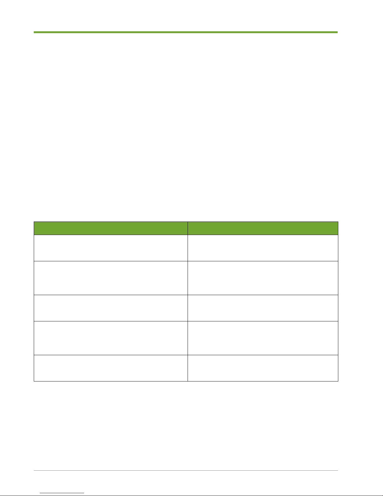
In addition to this guide, the following Violin Memory documents comprise the documentation suite
that will assist you with setting up, using and servicing the Violin 6000 Series Memory Array. These
guides are available for download from the Violin Memory Support site at http://www.violin-
memory.com/support/
This document... Provides this information...
Release Notes This document describes the new features, resolved
issues, known limitations and software upgrade
instructions for the current release.
Violin 6000 Series Memory Array User’s Guide This guide provides instructions for managing,
monitoring, and maintaining the Violin 6000 Series
Memory Array using the Violin Web interface and
Command Line Interface (CLI).
Violin 6000 Series Memory Array Slide Rail
Installation Guide
Violin 6000 Series Memory Array Cable Management
Installation Guide
Violin 6000 Series Memory Array Service Guide This guide describes how to safely replace the
Reference Documents
This guide provides instructions for installing the
Violin 6000 Series Memory Array slide rails in an
equipment rack.
This guide provides instructions for installing the
cable management arm on a Violin 6000 Series
Memory Array. It is included in the Violin 6000 Series
Memory Array shipping box.
system components in a Violin 6000 Series Memory
Array.
2
Violin 6000 Series Memory Array Installation Guide
535-0045-00 Rev 02
Page 7
Document Conventions
Safety Icons
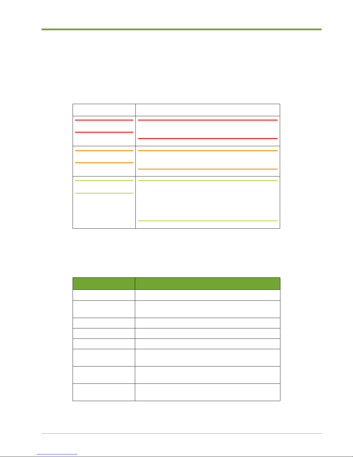
The table below summarizes warning, caution, and note icons used in this document and includes
sample text.
Safety Icons
Icon Sample Text
WARNING! WARNING! Only authorized, qualified, and trained
personnel should attempt to work on this equipment.
Caution: Caution: Follow the listed safety precautions when
working on the Violin 6000 Series Memory Array.
Note: Note: Read through this entire chapter and plan your
installation according to your location before installing
the equipment. The following procedures and the order
in which they appear are general installation guidelines
only.
Typographical Conventions
The following typographic conventions are used in this guide:
Format Meaning
Bold
Italic
Courier Command names, examples, and output.
Courier bold Input you must type exactly as shown.
<Courier italic> Information for which you must supply a value.
[] Optional command parameters are enclosed within
| Separates a set of command choices from which only
{} Required command parameters that must be specified
Typographical Conventions
User Interface text.
Provides emphasis and identifies variables and
document titles.
square brackets.
one may be chosen.
are enclosed within curly brackets.
535-0045-00 Rev 02
Violin 6000 Series Memory Array Installation Guide
3
Page 8

Security
Violin Memory, Inc., cannot be responsible for unauthorized use of equipment and will not make
allowance or credit for unauthorized use or access.
Contacting Violin Memory
To obtain additional information or technical support for Violin Memory products, contact us at:
Phone: 1-855-VIOLIN-5 (1-855-846-5465)
International: +1 650-396-1500 Extension 3
Web site: http://www.violin-memory.com
Email: [email protected]
When contacting Violin Memory Customer Support, please have the following information available:
• Model and serial number of the system for which you are requesting support.
• Software version.
• A brief description of the problem.
• Command Line Interface or Web interface access to the affected system.
4
Violin 6000 Series Memory Array Installation Guide
535-0045-00 Rev 02
Page 9

CHAPTER 1 Memory Array Hardware Installation
This chapter describes the hardware installation of a 6000 Series flash Memory
Array in the following sections:
• Installation and Configuration Overview on page 5
• Unpacking the Memory Array on page 7
• Standard System Configurations on page 9
• Installing the Memory Array on page 14
• Connecting the Memory Array to a Host or Network on page 23
• Connecting the ACMs for vMOS-6 on page 26
• Connecting Management Cables on page 27
• Securing the Memory Array to the Equipment Rack on page 29
See the Violin 6000 Series Memory Array User’s Guide for software installation and
upgrade instructions.
Installation and Configuration Overview
The Memory Array installation and configuration occurs in four distinct phases:
• Phase 1: Hardware Installation and Cabling
• Phase 2: First-time Memory Array Configuration
• Phase 3: Driver Installation and Configuration (if direct-attached connection is
used)
• Phase 4: Create LUNs on the Memory Array
Note: Instructions for installing drivers and configuring the Memory Gateways to
manage block storage are provided in the Violin 6000 Series Memory Array User’s
Guide.
535-0045-00 Rev 02
Violin 6000 Series Memory Array Installation Guide
5
Page 10
Chapter 1: Memory Array Hardware Installation
This chapter describes the first phase of a Memory Array implementation: the installation of the
Memory Array hardware and network cabling.
Hardware Installation is a five-step process consisting of the following procedures:
• Unpacking the Memory Array: In this step, unpack the Memory Array shipping box, inspect
the Memory Array components, and verify that you have the tools required to install the
Memory Array hardware.
• Rack-mounting the Memory Array Chassis: In this step, mount the Memory Array chassis
in the equipment rack using the slide-out rails and ground the equipment racks.
• Attaching the Cable Management Arm (if used): In this step, attach the cable management
arm to the Memory Array and the equipment rack.
• Connecting Power: In this step, connect the AC power cords to the Memory Array power
supplies and connect to a power source.
• Connecting the Interface Cables: In this step, connect the interface cables (Fibre Channel,
InfiniBand or 10GBe, PCIe) to the Memory Array chassis and to the client network.
The order of the procedures described in this chapter are offered as general guidelines only.
Depending on your installation environment, you may find it easier to perform the procedures in a
different order than they are presented here. For example, it may be easier to connect the network
management cables to the Memory Array chassis before you install the chassis in the equipment
rack.
Read through this entire chapter and plan your installation according to your location before
installing the Memory Array hardware.
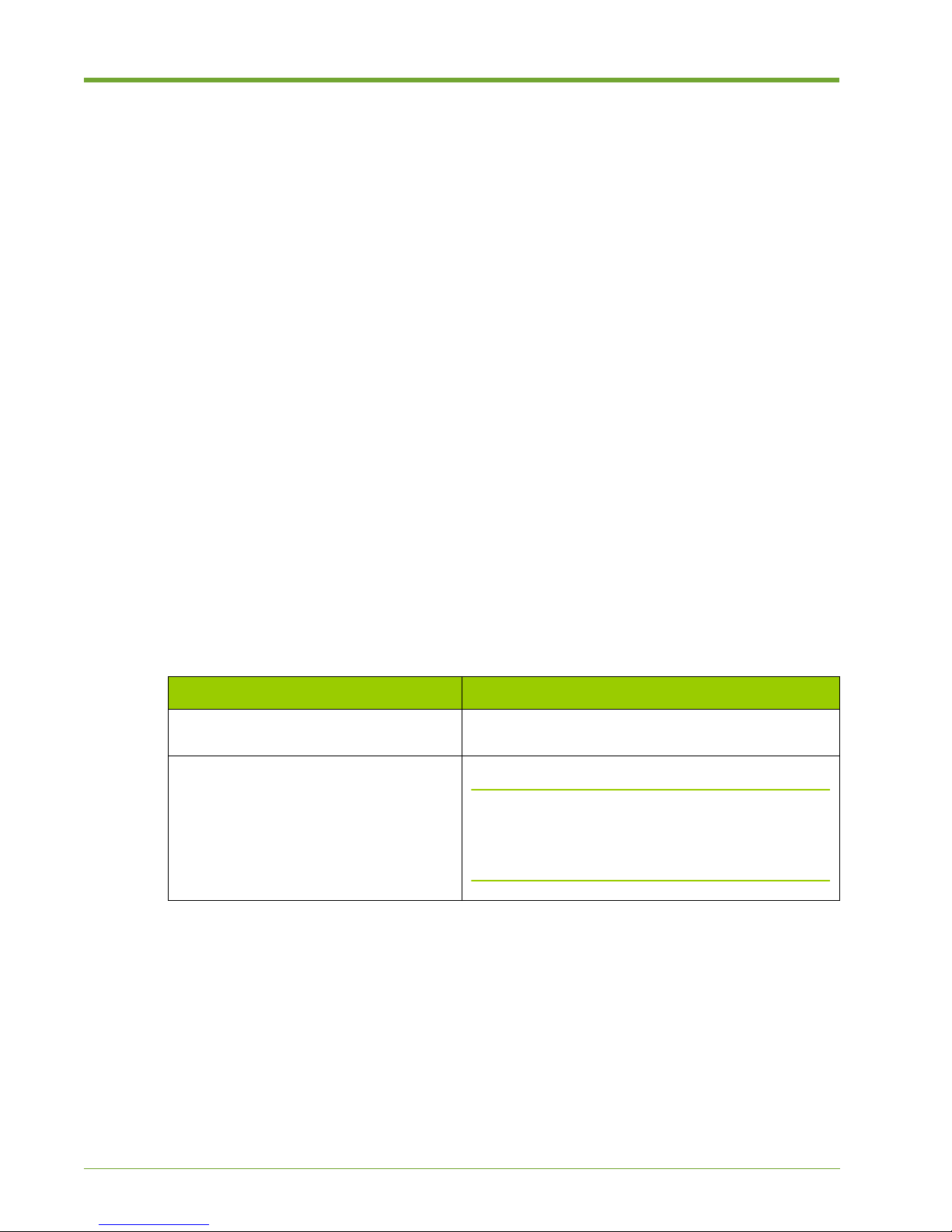
This chapter describes only the first phase of a Memory Array implementation. The remaining
phases can be found in the following sections:
Phase Chapter
2: First-time Memory Array
Chapter 2, System Setup and Configuration
Configuration
3: Driver Installation and Configuration Appendix A, InfiniBand Client Configuration
Note: Violin Driver installation is covered in the
Violin 6000 Series Memory Array User’s Guide and is
only necessary if you connect the Memory Array
directly to a host machine using PCIe cables.
Table 1.1 Phase Task Map
6
Violin 6000 Series Memory Array Installation Guide
535-0045-00 Rev 02
Page 11
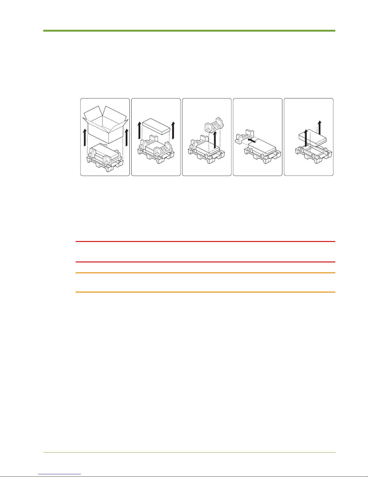
Unpacking the Memory Array
1234
5
The first step in the Memory Array hardware installation is to remove the Memory Array from the
shipping box.
Figure 1.1 Unpacking Memory Array
Unpacking the Memory Array
Remove the Memory Array from the shipping packaging and remove all packing materials. Visually
inspect the system for any damage. If any damage is detected, contact Violin Memory Customer
Support. For more information, see Contacting Violin Memory on page 4.
Unpack the supplied kits and confirm that all parts and components have arrived in good order.
WARNING! Only authorized, qualified, and trained personnel should attempt to work on this
equipment.
Caution: Because of the weight of the Violin 6000 Series Memory Array, two people are required to lift
and place the system in an equipment rack.
535-0045-00 Rev 02
Violin 6000 Series Memory Array Installation Guide
7
Page 12
Chapter 1: Memory Array Hardware Installation
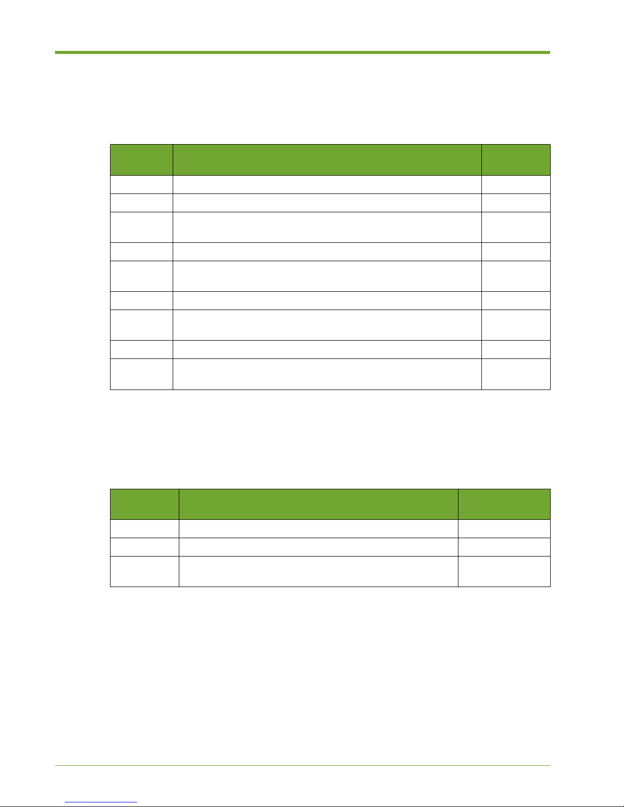
Parts and Accessory List
The table below lists the parts that may be included in the Memory Array shipping package.
Contents vary depending on the system ordered. Some optional accessories are not listed here.
Item
Number
Part Description Quantity
1 Memory Array 1
2 Flash VIMMs (preinstalled in Memory Array) 24, 44 or 64
3 C14-C19 Connector AC power supply cable, 6 ft, in Accessory
2
Box; connects to C20 inlets on the rear of the chassis.
4 DB9 to RJ-45, 6 ft rollover console cable, in Accessory Box 2
5 Rail Mounting Kit, includes two flat head screws, cage nuts and
1
screws
6 Rack ears 2
7 Host Bus Adapter (HBA) blanking panels (installed if direct-
4
attached system)
8 PCIe card (if direct-attached system ordered) 4
9 PCIe cable, 3 m, in Accessory Box (if PCIe cards ordered)
PCIe cable, 3 m (if a vMOS-6 system)
Table 1.2 Parts List
4
1
Installation Tools and Equipment
The table below lists the tools and equipment used during the installation process:
Item
Number
Tool Quantity
1 Phillips head screwdrivers, sizes 1 and 2 1 each
2 Computer system for direct connect configuration 1 or 2
3 CAT 5 Ethernet Cable with RJ-45 connectors, straight-
2
through or cross-over, depending on your installation
Table 1.3 Required Installation Tools
8
Violin 6000 Series Memory Array Installation Guide
535-0045-00 Rev 02
Page 13

Standard System Configurations
This section shows diagrams of standard configurations supported by Memory Arrays. It includes
the following configurations:
• SAN-attached Storage Configurations on page 9
• Direct-attached Storage Configurations on page 11
See Connecting the Memory Array to a Host or Network on page 23 for specific port-to-port cabling
instructions.
SAN-attached Storage Configurations
In many applications, it is preferable for the Memory Array to be shared by many hosts, many of
which may not be in the same rack as the Memory Array. In these scenarios, a storage area network
(SAN) or local area network (LAN) connection is preferable. The Memory Array can connect to the
SAN via Fibre Channel or InfiniBand, or the LAN via 10GbE iSCSI.
A Memory Gateway is used to provide the SAN/LAN block storage function. The Violin Memory
software application installed on the Memory Gateways manages the network connectivity and
provides storage virtualization services such as LUN provisioning, masking and exporting.
Standard System Configurations
See the Violin 6000 Series Memory Array User’s Guide for information on managing clusters and
configuring the system.
Note: A mix of network interface cards (NICs) in one Memory Array system is not supported.
Fibre Channel and iSCSI ports on the Memory Gateway may be connected either directly to specific
hosts or to switches. The switches may be standalone switches for use within a rack or networked
switches that connect large numbers of hosts across the data center. The latter case is the most
common.
Internal Memory Gateways
The Memory Array includes two internal Memory Gateways. Each internal Memory Gateway
supports two network interface modules (shown in Figure 1.2), each of which can support the
following:
• Four 8 Gbps Fibre Channel ports that auto-negotiate down to 4 Gbps
• Four InfiniBand ports operating at 4X Quad Data Rate (QDR)
• Four 10GbE iSCSI ports
535-0045-00 Rev 02
Violin 6000 Series Memory Array Installation Guide
9
Page 14
Chapter 1: Memory Array Hardware Installation
Fibre Channel
or InfiniBand Switch
Memory Array
Memory Gateway B
(NIC slots C and D)
Memory Gateway A
(NIC slots A and B)
D C B A
Fibre Channel
or InfiniBand Switch
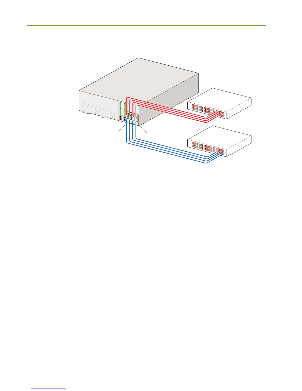
Figure 1.2 High-availability SAN-attached via Dual Internal Memory Gateways
Figure 1.2 shows the supported cable configuration when setting up a high-availability (HA) system.
This is the only supported HA configuration for the 6000 Series Memory Array. Memory Gateway A
manages connectivity through NIC slots A and B; Memory Gateway B manages connectivity
through NIC slots C and D.
Memory Gateways can use up to eight ports of 8 Gbps FC or 10GbE to connect to network
switches. InfiniBand ports on the Memory Array should be connected to InfiniBand switches in a
high-availability configuration.
Understanding Port Numbering
When connecting the interface cables in a SAN-attached configuration, it is important to know the
ports from which LUNs are exported from the Violin Web interface. Figure 1.3 shows the slot and
port numbers for Fibre Channel cards installed in the system, along with the representative CLI
values for each port. If there are more than two ports per card, the numbers increase from top to
bottom on the card.
10
Violin 6000 Series Memory Array Installation Guide
535-0045-00 Rev 02
Page 15

Standard System Configurations
Figure 1.3 Memory Gateway NIC Slots and Fibre Channel Port Numbers
Note that the physical port numbers on the network interface cards (NICs) are not aligned with their
corresponding port names in the CLI, as shown in Figure 1.3. For example, in a Fibre Channel
environment, NIC port A1 is shown as “hba-a1” in the CLI, and NIC port C1 is also shown as “hbaa1” in the CLI. This is because the two Memory Gateways, shown with their CLI representations
above (mg-a and mg-b), separately manage two NICs each.
InfiniBand and iSCSI cards are also supported. Their port numbers are represented in the CLI as
follows:
• InfiniBand: hca-a1, hca-a2, etc.
• iSCSI: eth-a1, eth-b1, etc.
Note: To verify the actual port numbering shown in the CLI, log in to the Memory Gateway master
and then run the “show targets” command.
Direct-attached Storage Configurations
PCI Express (PCIe) is the primary interconnect for direct-attached storage configurations. It is also
possible to use Fibre Channel without a SAN or switch, but this is treated as a SAN-attached
storage configuration. See SAN-attached Storage Configurations on page 9.
Note: vMOS-6 requires that the Array Controller Modules (ACMs) be externally connected to
each other to interconnect the internal Memory Gateways. Data Management features available in
vMOS-6, such as snapshots and thin provisioning, are not supported in PCIe direct-attached
configurations. See Connecting the ACMs for vMOS-6 on page 26 for details.
535-0045-00 Rev 02
Violin 6000 Series Memory Array Installation Guide
11
Page 16
Chapter 1: Memory Array Hardware Installation
Each Array Controller Module (ACM) provides two PCIe x8 Gen2 ports, each of which has a 40
Gbps nominal bit rate. The Memory Array has two ACMs, with all four of the ports available to host
computers.
Multiple direct-attached storage configurations are available depending on the number of hosts and
whether the hosts require shared access to the volumes or LUNs within the Array. Typical
configurations are:
• Single Host: single or dual PCIe x8 connections from the host to the Memory Array.
• Two Hosts: single or dual PCIe x8 connections from each host to the Memory Array. Each
host has access to all volumes and flash on the Memory Array. Data may be shared.
Drivers for Direct-attached Configurations
A driver must be installed on the host machine if the Memory Array is directly attached to a Linux
or Windows host. In a direct-attached configuration, the Violin Memory driver enables the host
machine to access block storage on a Violin Memory Array.
See “Violin Drivers” in the Violin 6000 Series Memory Array User’s Guide for instructions on
installing the Linux driver. When available, a driver for Windows and the installation instructions can
be downloaded from the Violin Memory Customer Support site.
Direct Attached, Single Host
A direct-attached connection to a single host machine via dual PCIe x8 connections is supported.
For a dual configuration, the second PCIe x8 connection is required. This configuration also
increases system availability and bandwidth.
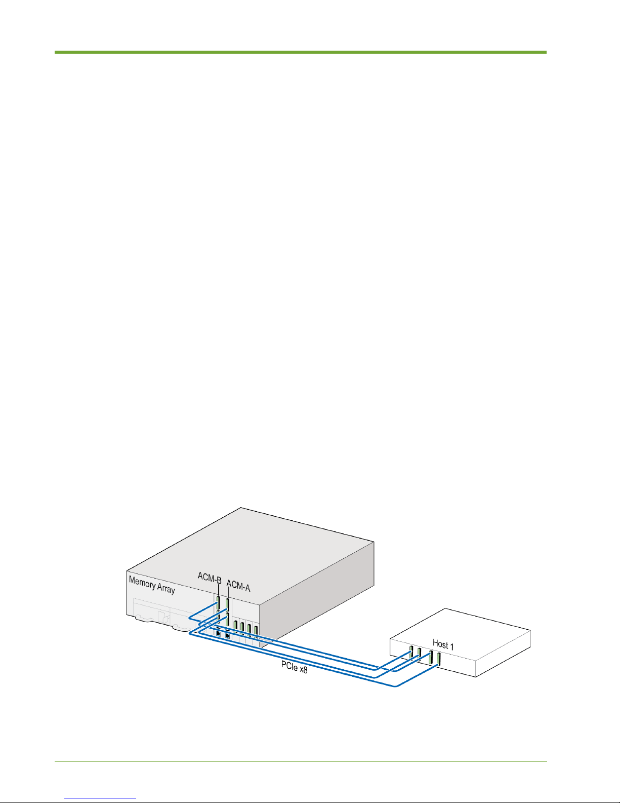
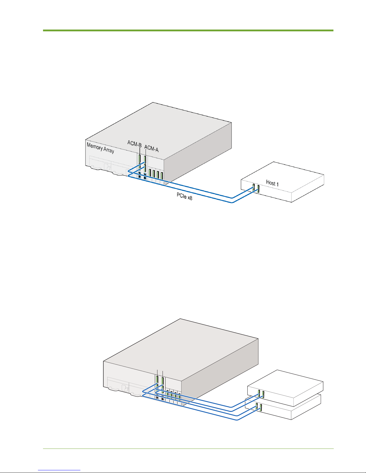
For improved High Availability (HA) protection, all four ports (two on each ACM) can be connected
to a single host for redundancy, as shown in Figure 1.4. The second set of connections present
another disk device with the same addressability as the first disk device. For a Linux system, the
device is shown as /dev/vtmsa.
Figure 1.4 Direct-Attached to Single Host for Redundancy
Connect one PCIe cable to the top PCIe connector on one of the ACMs, and connect the other PCIe
cable to the bottom of the same ACM. Repeat these connections for the other ACM.
12
Violin 6000 Series Memory Array Installation Guide
535-0045-00 Rev 02
Page 17
Standard System Configurations
Memory Array
Host 1
Host 2
PCIe x8
ACM-A
ACM-B
Connect the other ends of the PCIe cables to the host machine.
Connecting two PCIe cables from one ACM to the host machine is also supported (as shown in
Figure 1.5), however, utilizing both ACMs is recommended to take advantage of redundancy, as
described above.
Figure 1.5 Direct-Attached to Single Host
For a dual PCIe x8 connection to the host machine, connect one PCIe cable to the top PCIe
connector on one of the ACMs, and connect the other PCIe cable to the bottom of the same ACM.
Connect the other end of the PCIe cable to the host machine.
Direct Attached, Two Hosts
A direct-attached connection to two host machines is supported. Each host can be connected via
single or dual PCIe x8 connections. In dual configuration, the second PCIe x8 connection can be
used to increase bandwidth, redundancy and system availability.
535-0045-00 Rev 02
Figure 1.6 Direct-Attached to Two Hosts
Violin 6000 Series Memory Array Installation Guide
13
Page 18

Chapter 1: Memory Array Hardware Installation
For a dual PCIe x8 connection to two host computers, connect one PCIe cable to the top PCIe
connector on one of the ACMs, and connect the other PCIe cable to the bottom of the same ACM.
Connect the other end of the PCIe cable to the host machine. Connect the second host machine to
the other ACM in the same manner.
Where hosts share the same volume, a mechanism is needed to ensure the two hosts share the
volume productively and do not overwrite each other’s data. This can be done via a clustered file
system (e.g., GPFS, GFS, Veritas) or by partitioning the volume and explicitly assigning partitions
to each host over PCIe.
Installing the Memory Array
Follow the steps in this section to install the Memory Array in an equipment rack and to connect the
system directly to a host machine or to a network.
Managing Thermal Heat Impact Within the
Equipment Rack
Follow these recommendations to minimize the heat impact within an equipment rack when
deploying Memory Arrays in a high-density configuration:
• Equipment racks should be populated with the heaviest and most power-dense equipment at
the bottom. Install the Memory Arrays from the bottom up, for the following reasons:
— Weight: To maintain the lowest center of gravity.
— Cooling: To give best access to cold air inlet coming from the floor.
— Serviceability: To allow ease of access during service, as the system modules are
accessible from the top.
• Check and install thermal barriers, special baffling or direct ducting if possible to prevent hot
aisle air recirculating into the cold aisles, raising inlet temperatures and therefore, raising the
temperature of Memory Arrays.
• To the greatest extent possible, remove airflow obstructions from the intake and exhaust
openings of the Memory Arrays mounted in the rack. Thus, proper cable management
technique is recommended. It is recommended that data and power cables be grouped when
routing and tying.
Tying power cables at the bottom of the cable management arm and tying data cables at the
top of the cable management arm help minimize airflow restriction.
• Chilled air is pulled through the front and exhausted through the rear by the fans in the
Memory Arrays. Recirculation of hot air exiting the back of the rack into the front of the rack
should be eliminated as much as possible.
Install blanking/filler plates to all empty “U” slots in the racks to prevent both cold air from
bypassing server inlets and to avoid exhaust air from recirculating back to the inlets.
• The recommended operating temperature ranges for data centers—according to ASHRAE
(American Society of Heating, Refrigeration and Air-Conditioning)—is 64.4°F (18°C) for lowend and 80.6°F (27°C) for high-end. When deploying multiple Memory Arrays in the same
rack, you should monitor ambient and inlet temperature rise and may wish to adjust AC
settings in the data center to provide appropriate temperature levels. Violin Memory
recommends that the ambient temperature be maintained at around 25°C.
• As an optional but not necessary practice, you could consider racking Memory Arrays with 1U
separation to reduce exhaust airflow restrictions and to enable ease of cable management.
14
Violin 6000 Series Memory Array Installation Guide
535-0045-00 Rev 02
Page 19
Installing the Memory Array
• To reduce heat build-up inside high-density racks, top exhaust fans or door exhaust fans can
be installed.
Installing the Slide Rails
This section describes attaching the inner slide rails to the Memory Array chassis and mounting the
slide rails and Memory Array chassis to an equipment rack. If you are installing the Memory Array
in a square-hole equipment rack, the slide rails contain front and rear toolless mounting brackets
that click and lock into place.
The slide rail kit should include the following:
• Two slide rails
• Two flat head screws for mounting the rails to the Memory Array chassis
Caution: Improperly mounted rack-mounting brackets and slide rails can cause the product to fall.
Caution: Because of the weight of the Violin 6000 Memory Array, two people are required to lift and place
the system in an equipment rack.
Note: You must be able to access the rear of the Memory Array and the equipment rack during
installation.
To install the slide rails:
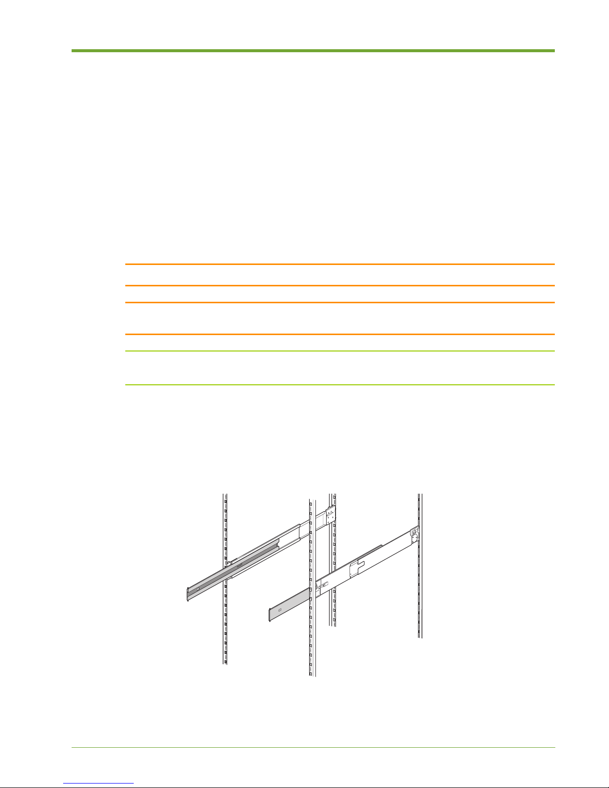
1. Locate the left and right slide rails. The left slide rail is labeled “LEFT FRONT” on the outside
front of the rail; the right slide rail is labeled “RIGHT FRONT.”
Figure 1.7 Slide Rails in Equipment Rack
535-0045-00 Rev 02
Violin 6000 Series Memory Array Installation Guide
15
Page 20

Chapter 1: Memory Array Hardware Installation
Inner Rail
Sections
Locking
Mechanism
Note: The Memory Array is a 3U storage system. When identifying the location of the slide rails,
make sure to allow for enough space above and below the Memory Array to accommodate other
devices in the equipment rack. The bottom of the Memory Array chassis rests .125 inches below
the bottom of the slide rails; the lid is 2 inches above the top of the slide rails.
2. Install the slide rails at the appropriate height in the equipment rack. Orient the slide rails so
they slide out to the front of the equipment rack.
Removing the Inner Slide Rail Sections
Fully extend the slide rails from the equipment rack until the rails click into place.
Figure 1.8 Removing the Inner Slide Rail Sections
3. Press the spring-loaded locking mechanisms on the outside of both inner rail sections and
then pull out and remove the inner slide rail sections from the left and right slide rails.
Note: Keep track of the left and right inner slide rail sections. The left must attach to the left of
the chassis; the right must attach to the right of the chassis.
16
Violin 6000 Series Memory Array Installation Guide
535-0045-00 Rev 02
Page 21
Installing the Memory Array
Attaching the Inner Slide Rail Sections to the Memory Array
Chassis
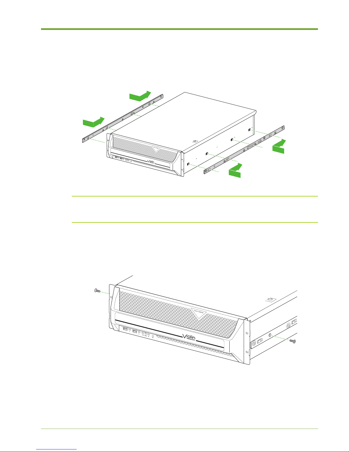
1. Locate the four rectangular cutouts on the side of the inner rail section.
Figure 1.9 Attaching the Inner Rail Sections to the Memory Array
Note: Make sure to attach the left and right inner slide rail sections to the correct sides of the
chassis. The inner slide rail sections are marked as follows: “B-L” on the left section and “B-R” on
the right section.
2. Align the four cutouts over the four hooks on the outside of the Memory Array chassis and then
slide the inner rail section toward the rear of the Memory Array chassis until it is securely in
place.
Figure 1.10 Securing the Inner Rail Sections to the Memory Array
3. Using the two flat head screws from the slide rail kit, secure the inner rail sections to the
Memory Array chassis.
535-0045-00 Rev 02
Violin 6000 Series Memory Array Installation Guide
17
Page 22
Chapter 1: Memory Array Hardware Installation
Installing the Cage Nuts
Cage nuts and screws are included in the accessory kit to secure the Memory Array to the top hole
on the rack ears and the equipment rack. Use either the supplied cage nuts or the screws,
depending on the style of your equipment rack.
Note: If the equipment rack in which the Memory Array will be installed is a square-hole rack, it
is recommended that you install the cage nuts before mounting the Memory Array.
Use the cage nuts for square-holed equipment racks. If the equipment rack has threaded holes, you
can secure the Memory Array to the equipment rack after the Memory Array is installed.
To install the cage nuts:
1. Identify the location in the equipment rack where the cage nut will reside. The cage nut will
align with the top hole on the rack ear, which is two holes above the top clip on the slide rail.
2. Remove the screw from the cage nut and set it aside for later use.
3. Insert the cage nut into the equipment rack at the identified location.
4. Using a flat-blade screwdriver, from the inside of the equipment rack, compress the cage nut
clip until the cage nut locks into place.
5. Repeat step 4 using another cage nut on the other side of the equipment rack.
Attaching the Rack Ears (Optional)
Note: Optional rack ears are included in the Memory Array shipping box if you do not want to
secure the Memory Array chassis to the equipment rack using the front bezel. Securing the Memory
Array to the equipment rack is covered on page 29.
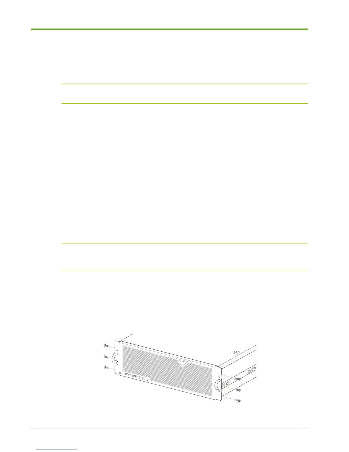
Attach the rack ears to the two front corners of the Memory Array chassis to assist with sliding the
system in an out of the equipment rack.
1. Remove the rack ears and six flathead screws from the accessory kit.
Figure 1.11 Attaching the Left Cable Management Bracket and Routing the Cables
18
Violin 6000 Series Memory Array Installation Guide
535-0045-00 Rev 02
Page 23
Installing the Memory Array
Spring-loaded Lock
2. Using a #1 Phillips screwdriver, attach the rack ears to both sides of the chassis.
Note: Do not secure the rack ears to the equipment rack until all of the cables are connected to
the Memory Array.
Mounting the Memory Array in the Equipment Rack
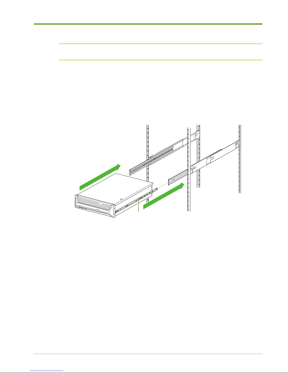
1. With another person, lift the Memory Array and then align the left and right inner rail sections
that you mounted on the Memory Array chassis with their original channels located on the
inside of the slide rails.
Figure 1.12 Mounting the Memory Array on the Equipment Rack
2. Carefully push the Memory Array into the slide rails until the inner rail sections lock into place,
making sure that the Memory Array remains level throughout.
3. Press in the spring-loaded locking mechanism on the outside of both inner rail sections and
then push the whole assembly back into the equipment rack.
Connecting the Cable Management Arm
See the Violin 6000 Series Memory Array Cable Management Installation Guide included in the
Memory Array shipping box for instructions on installing the cable management arm.
Skip to Grounding the Memory Array on page 20 if you are not using the Violin cable management
arm.
535-0045-00 Rev 02
Violin 6000 Series Memory Array Installation Guide
19
Page 24
Chapter 1: Memory Array Hardware Installation
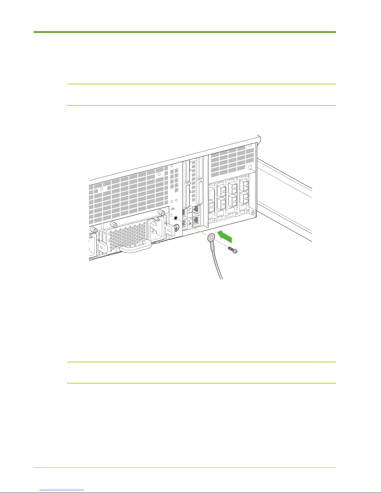
Grounding the Memory Array
This procedure describes the connection of the equipment ground from the equipment rack to the
Memory Array chassis.
Note: Maintain reliable earthing of rack-mounted equipment. Supply extra connections, other
than the direct connections to the branch circuit, such as using power strips.
Figure 1.13 Securing an Equipment Ground Wire
To connect an equipment ground wire to the Memory Array:
1. Cut an appropriate length of wire for the equipment ground wire for your location and strip 1/2”
of insulation from both ends of the wire. Use appropriately sized wire for your equipment
application. Minimum acceptable wire gauge is 8 AWG.
2. Using a size 10-32x1/2” (maximum length) screw (not included), secure the equipment ground
wire to the equipment ground connection on the rear of the chassis.
Note: A UL listed ground lug must be used. Check your local code requirements or contact a
licensed electrician.
3. Secure the other end of the equipment ground wire to the equipment rack using an
appropriately sized screw for the equipment rack. If the equipment rack has a designated
ground location, secure the ground wire to this location.
20
Violin 6000 Series Memory Array Installation Guide
535-0045-00 Rev 02
Page 25
Installing the Memory Array
Power Supply B
Power
Supply A
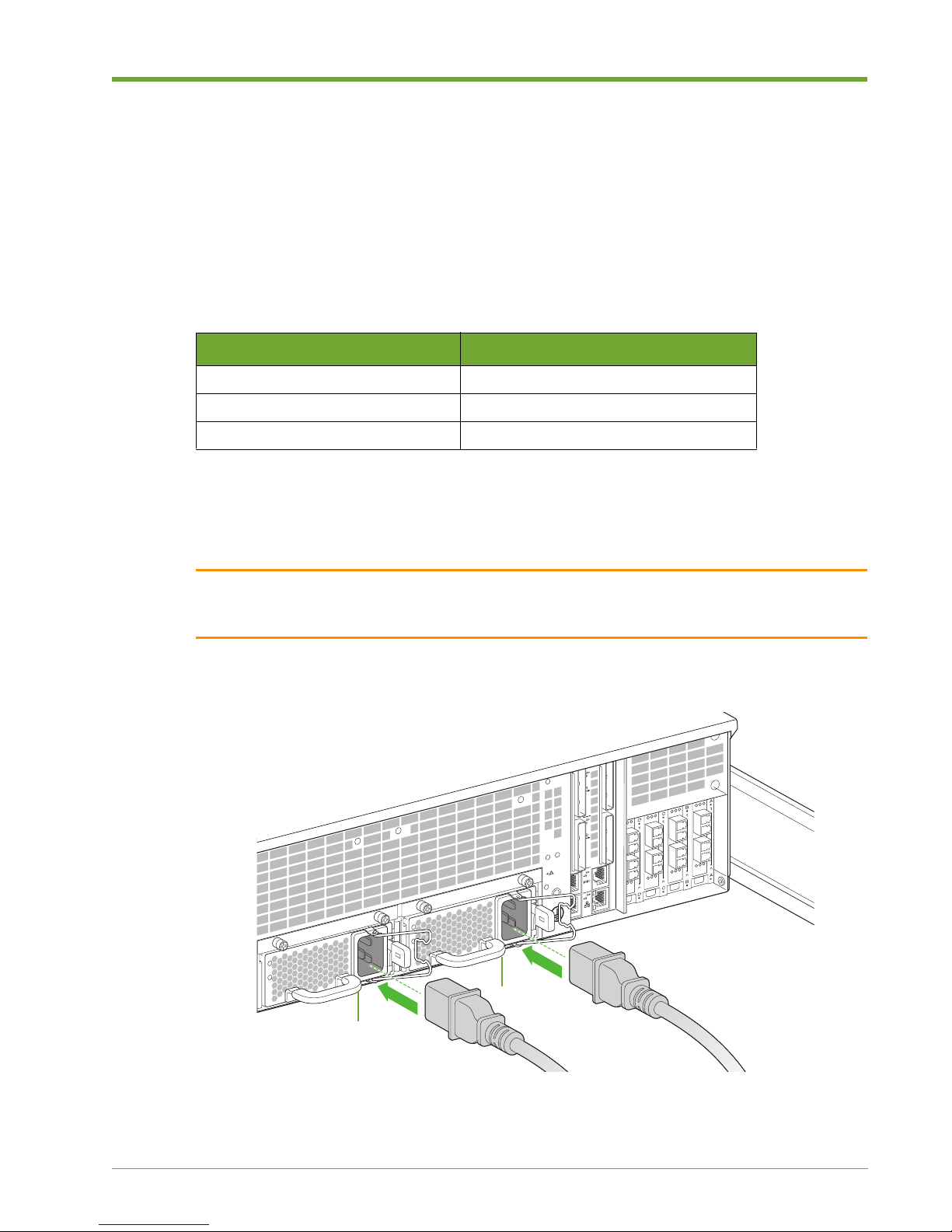
Connecting AC Power Cords to the System
The Memory Array requires 200-264 volts, 47-63 Hz, single phase, 15 A circuits. The power
requirements are for the entire chassis.
The power cords have IEC 320 C19 plugs for the Memory Array, and C14 plugs to the data center
power strip.
The Memory Array has the following power requirements. See Memory Array System Specifications
on page 62 for more information.
Item Requirement
Voltage Input Range 200-264 V AC 50/60 Hz (15 A Max)
Supported Operating Range 180-264 V AC
Supported Frequency Range 47-63 Hz
Table 1.4 Power Requirements
The Memory Array chassis has the AC power supplies installed prior to shipping. For redundancy
purposes, connect the AC power cords to both power receptacles on the Memory Array, and then
to different power circuits (if possible).
Caution: Consider the equipment connection to the supply circuit and the effect that overloading the
circuits might have on overcurrent protection and supply wiring. Also consider the appropriate equipment
nameplate ratings when addressing this concern.
Figure 1.14 Connecting the AC Power Cords
535-0045-00 Rev 02
Violin 6000 Series Memory Array Installation Guide
21
Page 26
Chapter 1: Memory Array Hardware Installation
Note: The Violin 6000 Memory Array AC power cords are not a standard configuration. Use only
the AC power cords supplied with your system.
To connect the AC power cords to the Memory Array chassis:
1. Locate the AC power receptacles at the rear of the Memory Array chassis.
2. Insert the power connector into the mating power receptacle on the rear of the Memory Array.
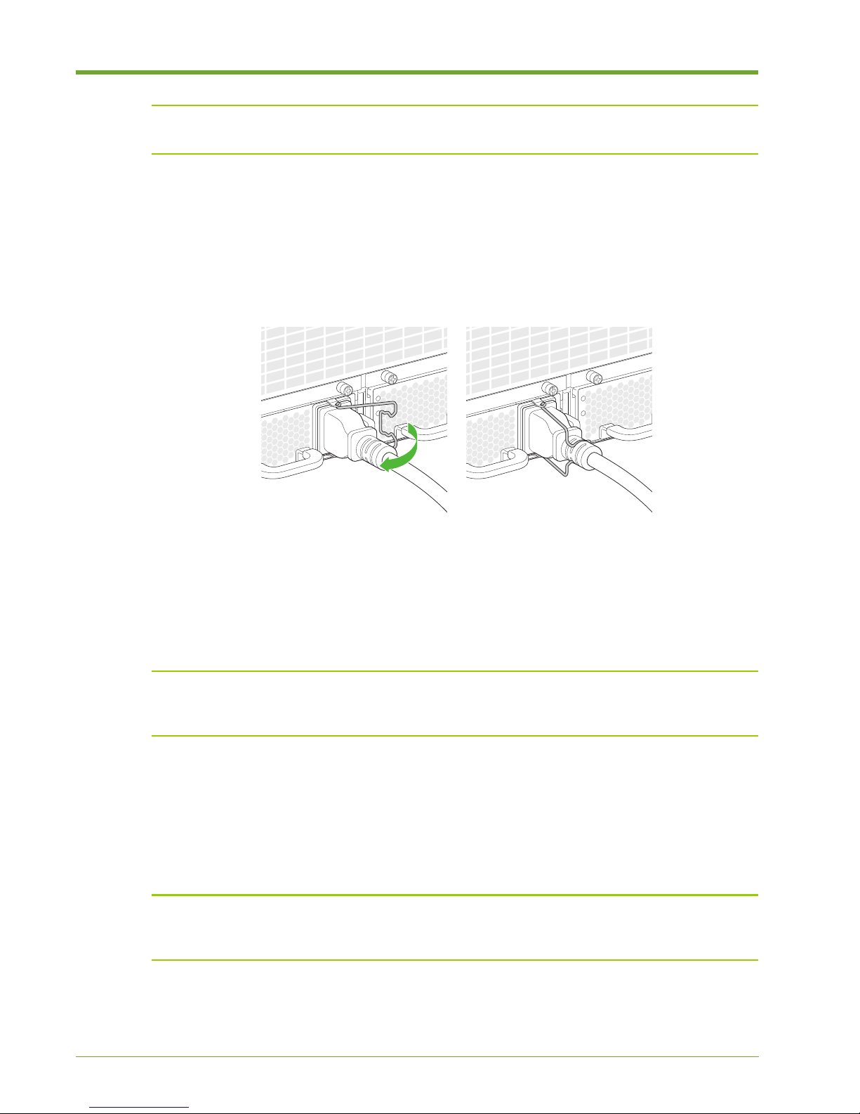
Figure 1.15 Securing the Power Cord Clips
3. Move the clip to the right and then secure it over the power cord.
4. Repeat steps 2-3 for the second AC power supply.
Powering up the Memory Array
Note: Always power on the Memory Array before the host computer to ensure PCIe
communication; PCIe hotplug is not supported. An alternate method is to reboot the host computer
after powering on the Memory Array to ensure that the host computer recognizes the system.
To complete the power on sequence:
1. Plug each AC power cord from the chassis into an AC outlet.
During the boot up process, the green Status LEDs will flash. The Memory Array is fully booted
when the Status LED is continuously lit.
Note: If the top LED on the power supply continues to blink green after the boot up process, the
power controller associated with the power supply is either missing, improperly seated or must be
replaced. Contact Violin Memory Customer Support for assistance.
2. If connected to a host computer, power on the host computer and log in as root on a Linux
system, or as an “administrator” on a Windows system to install the device driver. See “Violin
Drivers” in the Violin 6000 Series Memory Array User’s Guide for more information.
22
Violin 6000 Series Memory Array Installation Guide
535-0045-00 Rev 02
Page 27
Connecting the Memory Array to a Host or Network
PCIe Gen2 Ports
B
2
A
1
See the Violin 6000 Series Memory Array User’s Guide for information about rebooting and shutting
down the Memory Array and the internal modules.
Connecting the Memory Array to a Host or Network
This section describes the steps required to connect the various types of interface cables from the
Memory Array to a host or storage area network (SAN). See Standard System Configurations on
page 9 for general guidelines for all supported configurations.
Connecting PCIe Cables to the Memory Array
This section describes the steps required to connect a single Memory Array to a single host. Several
different direct-attached storage configurations are possible depending on the number of hosts and
whether those hosts require shared access to the volumes or LUNs within the Memory Array. See
Direct-attached Storage Configurations on page 11 for information on other direct-attached
configurations.
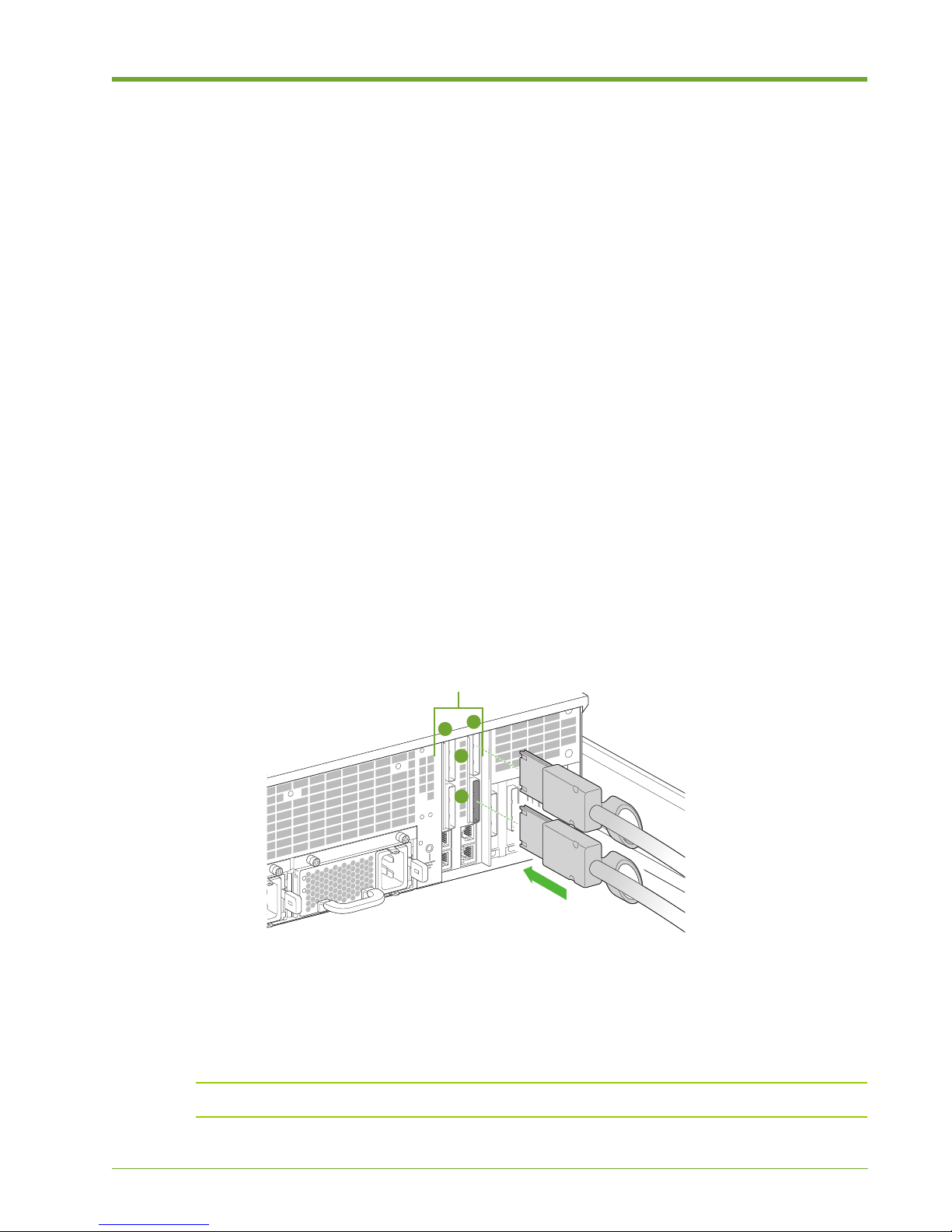
The Memory Array communicates with the direct-attached host computer using a PCI Express
(PCIe) connection. There are two Array Controllers Modules (ACMs) in the system. Each Array
Controller provides two PCIe x8 Gen2 ports, making four PCIe ports available to two hosts. Only
two external hosts are supported. Two PCIe cables must be used when connecting the Memory
Array to an external host.
To connect the PCIe cables to the Memory Array:
Figure 1.16 Connecting the PCIe Cables to the Memory Array
1. Align the connectors of the PCIe cables with the appropriate PCIe connectors at the rear of the
Memory Array chassis. Note the arrangement of the ACMs: ACM A is on the right and ACM B
is on the left. PCIe port 1 is on the top and port 2 is on the bottom.
2. Securely plug the PCIe cables into the PCIe connectors of the appropriate PCIe ports.
Note: Ensure that the bend radius of the PCIe cable is greater than 1.9".
535-0045-00 Rev 02
Violin 6000 Series Memory Array Installation Guide
23
Page 28
Chapter 1: Memory Array Hardware Installation
Fibre Channel, 10 GbE iSCSI
or InfiniBand Ports
To connect the PCIe cables to a host computer:
1. Install a PCIe Host Bus Adapter (HBA) card into the available PCIe slot in the host computer,
ensuring that it is securely seated into the PCIe slot. See the documentation that came with
the PCIe card for installation instructions.
2. Orient the unconnected end of the PCIe cables so that they align with the PCIe connectors on
the back of the host computer.
3. Securely plug the cables into the PCIe connectors.
Connecting Network Interface Cables to the Memory
Array
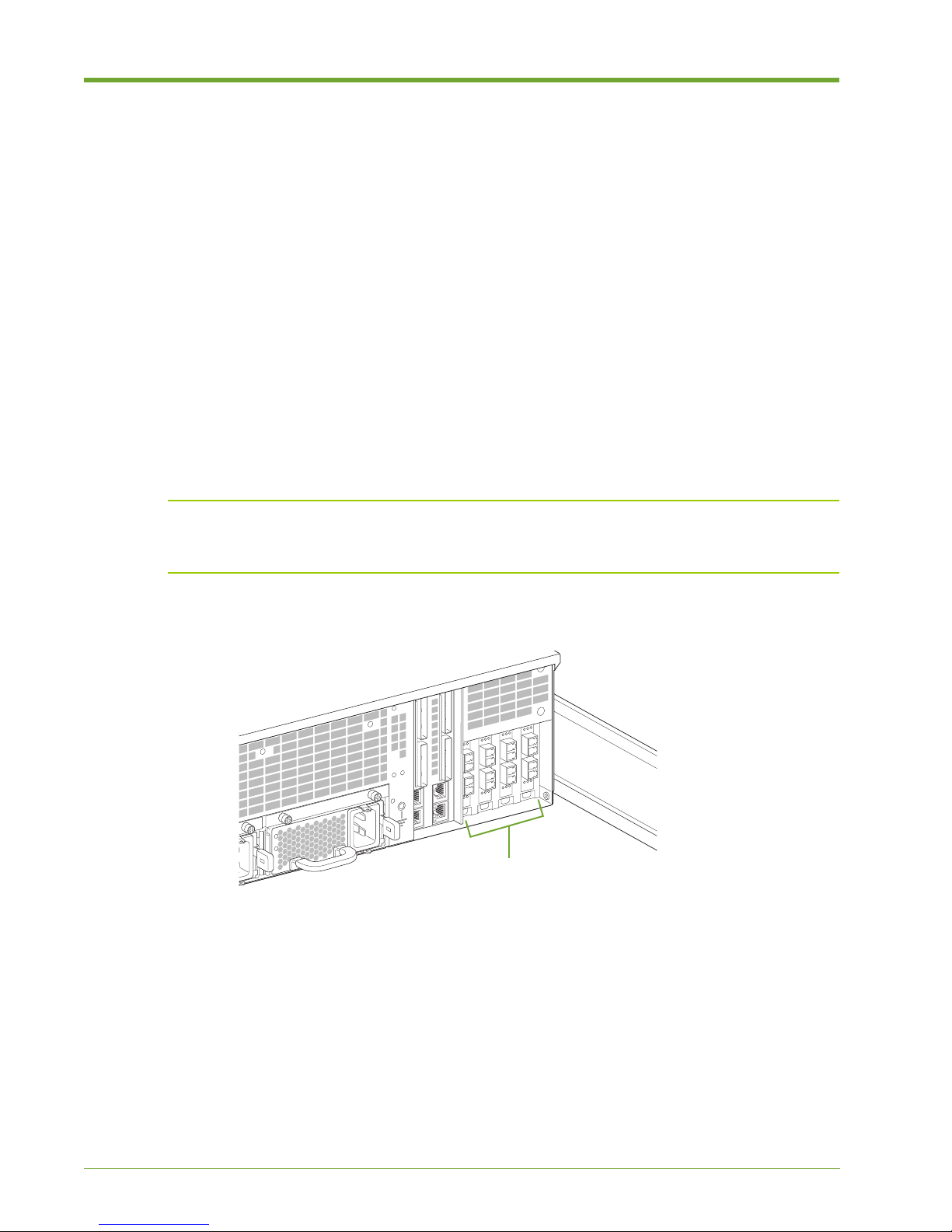
This section describes the steps required to connect the network interface cables from the Memory
Array to a storage area network (SAN) via Fibre Channel, InfiniBand or a Local Area Network (LAN)
via 10GbE iSCSI. See SAN-attached Storage Configurations on page 9 for instructions on the ports
to use on the Memory Array for the supported configurations, including a high-availability
installation.
Note: When connecting the interface cables in a SAN-attached configuration, it is important to
know the ports from which LUNs are exported from the Web interface. See Understanding Port
Numbering on page 10 for more information on the port numbering of the support cards.
Figure 1.17 Connecting Interface Cables to the Memory Array
Connecting Fibre Channel Cables
The dual 8Gbps ports on the Fibre Channel HBA are SFP+ with LC-style connectors. See Fibre
Channel Adapter Card Specifications on page 63 for more information.
1. Align one connector of the Fibre Channel cable with the appropriate Fibre Channel connector
at the rear of the Memory Array chassis.
2. Securely plug the Fibre Channel cable into the Fibre Channel connector of the appropriate
Fibre Channel port.
3. Connect the other end of the Fibre Channel cable to a host computer or Fibre Channel switch.
24
Violin 6000 Series Memory Array Installation Guide
535-0045-00 Rev 02
Page 29

Connecting the Memory Array to a Host or Network
Connecting iSCSI Cables
The 10 GbE NIC ports are SFP+ LC connectors. Ethernet/iSCSI Adapter Card Specifications on
page 65 for more information.
1. Align one connector of the iSCSI cable with the appropriate iSCSI connector at the rear of the
Memory Array chassis.
2. Securely plug the iSCSI cable into the iSCSI connector of the appropriate iSCSI port.
3. Connect the other end of the iSCSI cable to an iSCSI switch.
Connecting InfiniBand Cables
The InfiniBand adapter card uses QSFP 40Gb/s connectors. See InfiniBand Adapter Card
Specifications on page 64 for more information.
1. Align one connector of the InfiniBand cable with the appropriate InfiniBand connector at the
rear of the Memory Array chassis.
2. Securely plug the InfiniBand cable into the InfiniBand connector of the appropriate InfiniBand
port.
3. Connect the other end of the InfiniBand cable to an InfiniBand switch.
See InfiniBand Client Configuration on page 51 for an overview of InfiniBand driver installation and
client setup.
535-0045-00 Rev 02
Violin 6000 Series Memory Array Installation Guide
25
Page 30
Chapter 1: Memory Array Hardware Installation
PCIe Gen2 Ports
B
2
A
Connecting the ACMs for vMOS-6
Note: This cable connection is only required for vMOS-6.
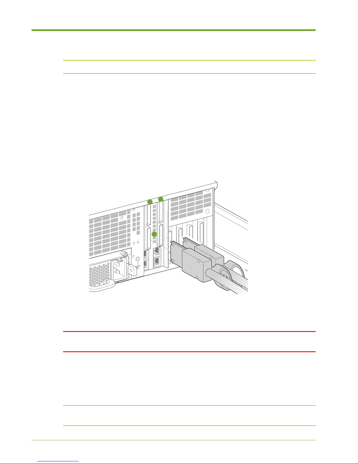
vMOS-6 requires that the ACMs be externally connected to each other to interconnect the internal
Memory Gateways. This cable connection enables a Non-Transparent Bridge (NTB), which allows
for high-bandwidth, low latency inter-cluster coordination between the two Memory Gateways for
effective management of thin provisioned LUNs and snapshots.
There are two Array Controllers Modules (ACMs) in the system. Each Array Controller provides two
PCIe x8 Gen2 ports. The ACMs communicate with each other using a PCI Express (PCIe)
connection. This section describes the steps required to connect the ACMs to each other.
To connect the PCIe cable:
Figure 1.18 Connecting the PCIe Cables to the ACMs
1. Using the supplied PCIe cable, align the connectors of both ends of the PCIe cable with the
bottom ports on the ACMs: ACM A port 2 and ACM B port 2, as shown in Figure 1.18.
WARNING! You must use the bottom PCIe ports on the ACMs for this connection. The top PCIe
ports must remain unused in this configuration.
2. Securely plug the PCIe cables into the PCIe connectors of the bottom PCIe ports.
There is no configuration required to enable this ACM-to-ACM connection. You can, however, verify
that NTB is configured and to view its status by using the “show ntb” commands. See Verifyi ng
NTB Link (vMOS-6 Only) on page 45 for more information.
Note: If you are using the cable management arm, route this cable in the arm along with the other
cables. Ensure that the bend radius of the PCIe cable is greater than 1.9".
26
Violin 6000 Series Memory Array Installation Guide
535-0045-00 Rev 02
Page 31
Connecting Management Cables
ID
1
2
n
1
1
n
D
D
1
n
C
C
1
n
B
B
A
A
B
A
B
A
B
A
B
A
A
B
Console Port A
Console Port B
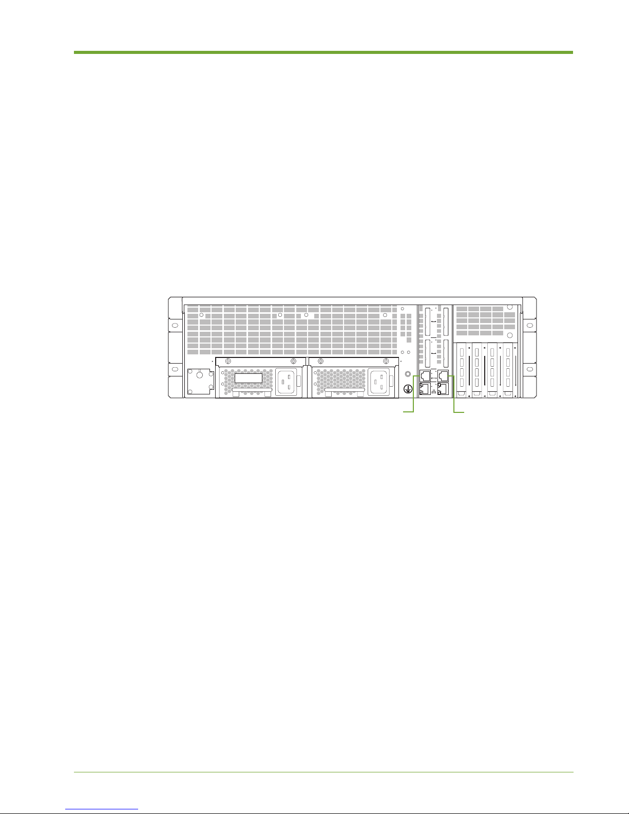
Configuring the Memory Array and gathering status about the system can be completed by
connecting to the console or Ethernet ports on the back of the chassis. Each method is described
in the following sections:
• Connecting the Console Cable on page 27
• Connecting the Ethernet Cable on page 28
Connecting the Console Cable
Use the serial console cable to connect a computer to the Memory Array for configuration
operations and retrieval of system status using the command-line interface (CLI).
Connecting Management Cables
Figure 1.19 Connecting the Console Cable to the Memory Array
To connect the console cable to the Memory Array and a computer:
1. Connect one end of the console cable to a serial console port A on the rear of the Memory
Array.
2. Connect the other end of the cable to a computer.
3. When you are ready to connect to the CLI, launch a terminal window, and then use the
following console settings:
— Bits per second: 115200
— Data bits: 8
— Parity: None
— Stop bits: 1
See System Setup and Configuration on page 31 for more information.
535-0045-00 Rev 02
Violin 6000 Series Memory Array Installation Guide
27
Page 32
Chapter 1: Memory Array Hardware Installation
ID
1
2
n
1
1
n
D
D
1
n
C
C
1
n
B
B
A
A
B
A
B
A
B
A
B
A
A
B
Ethernet Port AEthernet Port B
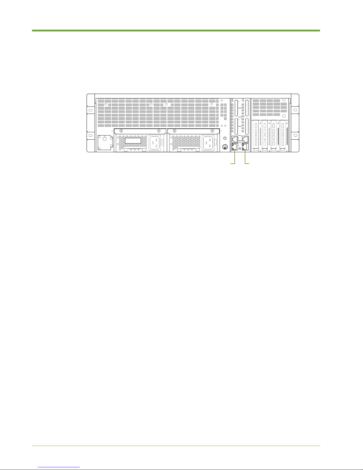
Connecting the Ethernet Cable
The RJ-45 10/100/1000 Ethernet cable connects the host computer to the command-line interface
(CLI) for configuration operations and retrieves system status.
Figure 1.20 Connecting the Ethernet Cable to the Memory Array
For a direct host-to-system Ethernet connection, use a straight-through or cross-over RJ-45 to RJ45 CAT5 Ethernet cable.
You can also use a straight-through or cross-over cable to connect the Memory Array to a switch,
hub or other network equipment, provided that the host and the system can communicate with each
other.
To connect the Ethernet cable to the Memory Array and the host computer:
1. Connect one end of the Ethernet cable to one of the bottom Ethernet connectors on the rear of
the Memory Array.
2. Connect the other end of the Ethernet cable:
• If directly connecting to the host machine, plug the cable into the Ethernet connector on
the host.
• If connecting to customer network equipment, plug the cable into the customer network
equipment, such as a network switch. Use a second Ethernet cable to connect the host
computer to the customer network equipment.
28
Violin 6000 Series Memory Array Installation Guide
535-0045-00 Rev 02
Page 33
Securing the Memory Array to the Equipment Rack
Securing the Memory Array to the Equipment Rack
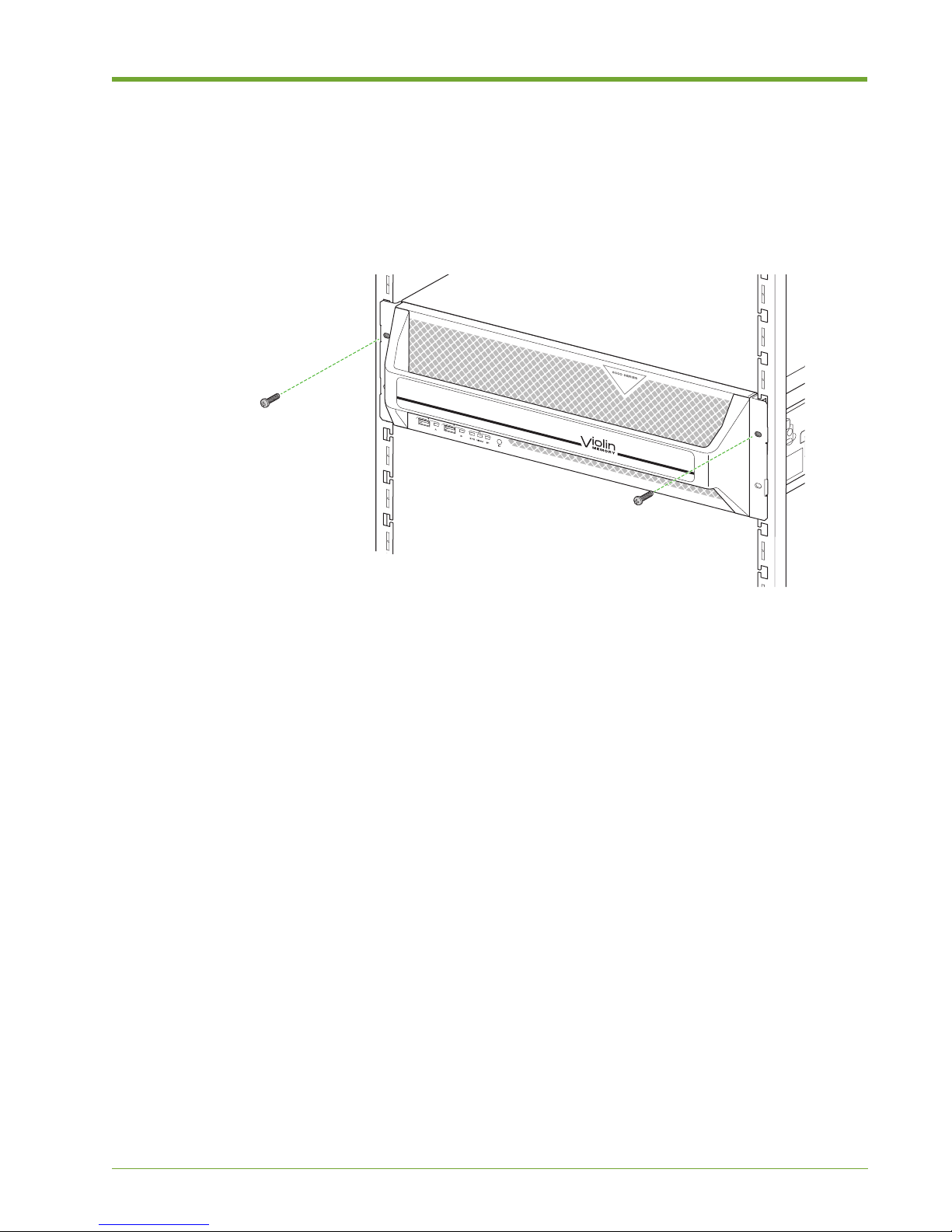
Follow these steps to secure the front bezel on the Memory Array to a square-hole equipment rack
using either the previously-installed cage nuts, or to a threaded equipment rack using the screws
included in the accessory kit.
Figure 1.21 Securing the Memory Array to the Equipment Rack
Use either the supplied cage nuts or the screws, depending on the style of your equipment rack.
See Installing the Cage Nuts on page 18 if you have not installed the cage nuts for a square-hole
equipment rack.
• Using the screws removed from the cage nuts, or the separate screws for a threaded
equipment rack, insert the screws into the top holes on the front bezel and then tighten the
screws.
535-0045-00 Rev 02
Violin 6000 Series Memory Array Installation Guide
29
Page 34

Chapter 1: Memory Array Hardware Installation
30
Violin 6000 Series Memory Array Installation Guide
535-0045-00 Rev 02
Page 35

CHAPTER 2 System Setup and Configuration
When a new Violin 6000 Memory Array is powered on for the first time, all
configuration settings remain at their default values. You must change the default
settings to communicate with the Memory Array over your network(s).
This chapter explains how to update and set up the system settings on a new Violin
6000 system using the configuration wizard in the following sections:
• Completing the Configuration Wizard on page 32
• System Verification and Management on page 37
• Troubleshooting on page 47
Note: If you connected the Memory Array directly to a host machine using PCIe
cables, you must install a driver to enable the host machine to access block storage
on the Array. See “Violin Drivers” in the Violin 6000 Series Memory Array User’s
Guide after completing the configuration steps in this chapter.
535-0045-00 Rev 02
Violin 6000 Series Memory Array Installation Guide
31
Page 36
Chapter 2: System Setup and Configuration
Completing the Configuration Wizard
When a new Violin 6000 Memory Array is powered on for the first time, all configuration settings
remain at their default values. Follow the steps in this section to configure the Memory Array for the
first time.
Default System Settings
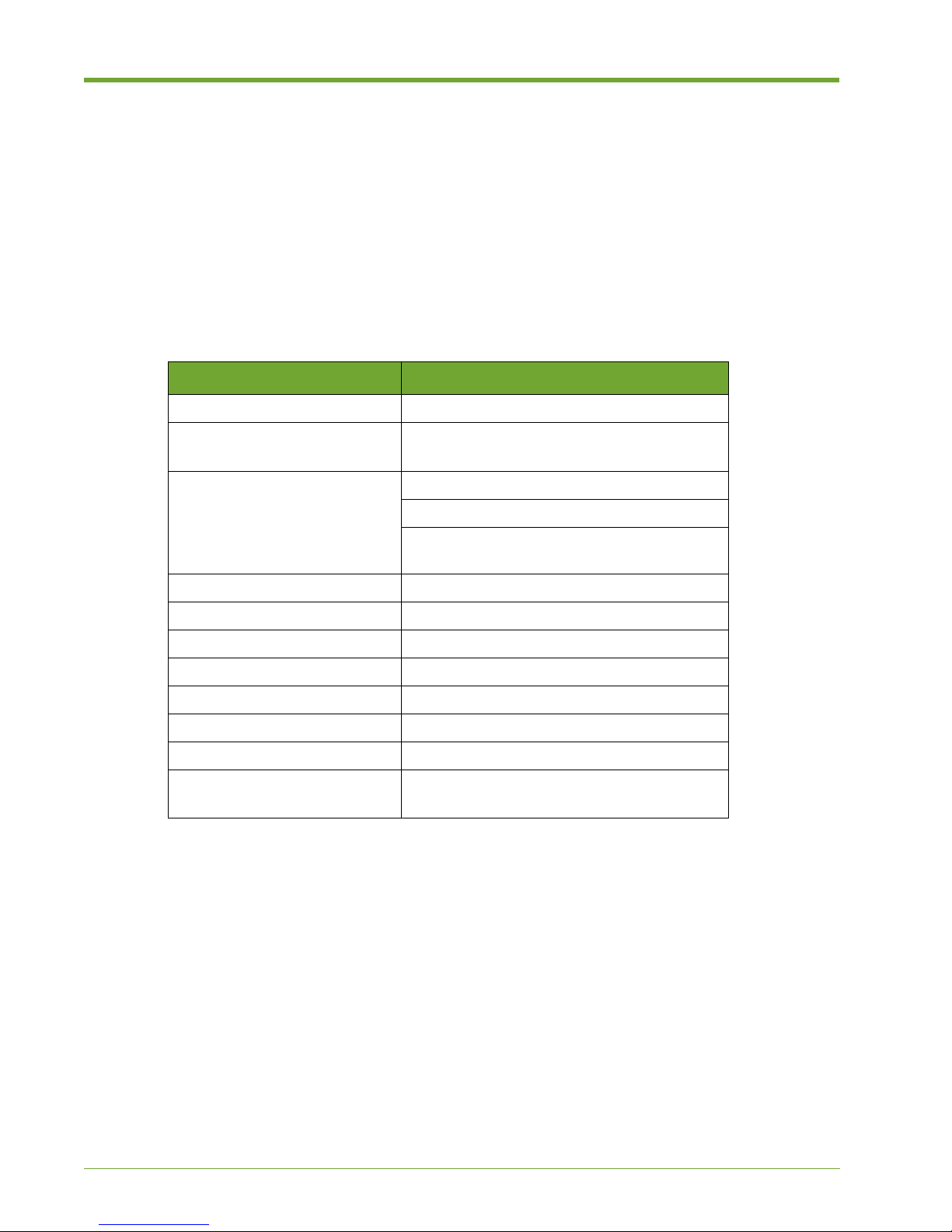
The Memory Array’s default settings are listed in Table 2.1. Change these settings using the CLI
over a SSH session or using a serial port connected to the Memory Array.
Setting Name Default Value
Cluster Name vmem-array
Host Name vmem-array-acma
vmem-array-acmb
IP Addresses 192.168.1.10 (ACMa, static)
192.168.1.11 (ACMb)
192.168.1.12 (ACM Management IP address)
also known as a VIP (Virtual IP address)
IP Netmask 255.255.255.0
IP Default Route 192.168.1.1
Clock Source NTP
Shell Connectivity Serial, SSH (port 22)
Serial Port Settings 9600 Baud, No Parity, 8 bits, 1 stop
User Name "admin"
Password blank
Flash VIMM Format 65% for SLC
84% for MLC
Table 2.1 Memory Array System Default Settings
32
Violin 6000 Series Memory Array Installation Guide
535-0045-00 Rev 02
Page 37
Configuration Checklist
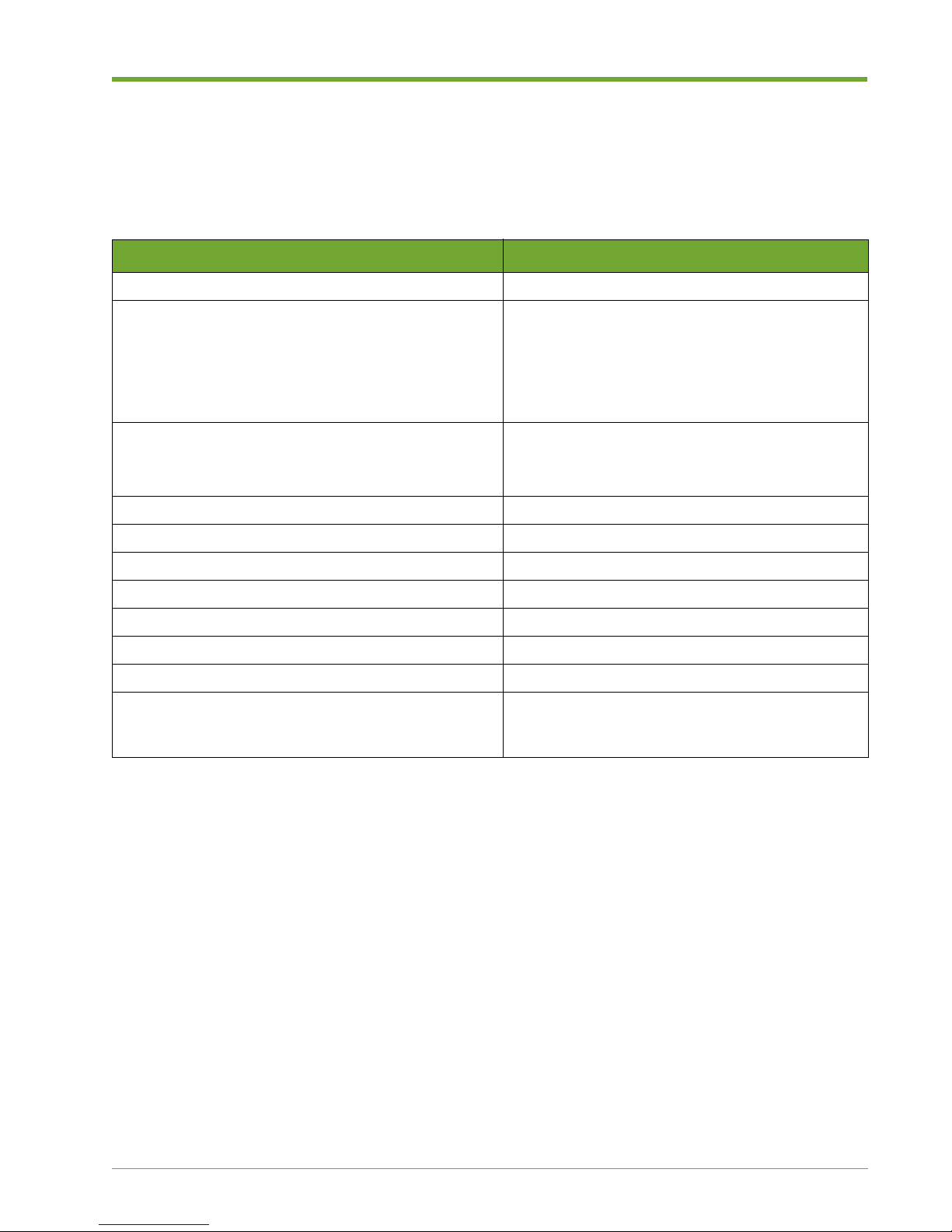
Before you begin configuring the Memory Array and the Memory Gateways, make sure that you
gather the following information from the network administrator. These items must be available to
complete the initial configuration.
Information Notes
A host name to be used for the system
Four host IP addresses within the same subnet:
• Array Controller Module A (acm-a) host IP address
• Array Controller Module B (acm-b) host IP address
• Memory Gateway A (mg-a) host IP address
• Memory Gateway B (mg-b) host IP address
Two management IP addresses:
• ACM management IP address
• Memory Gateway management IP address
ACM management IP Netmask
Completing the Configuration Wizard
Memory Gateway management IP Netmask
Netmask
DNS server IP address
Domain name
Default Gateway IP address
NTP server IP address and time zone
E-mail hub and port for auto support feature (if
callhome.vmem.com cannot be reached over TCP port
25 due to corporate firewall restrictions)
Table 2.2 Initial System Configuration Checklist
Completing the Configuration Wizard for a New
System
This section describes initial (first time) configuration of the Memory Array. Configuration is
completed by connecting a serial console cable to the Memory Array and then using the
Command Line Interface (CLI) to configure the system.
1. Connect a serial cable from your computer to console port A on the back of the Memory Array.
(Port A is the right console port on the back of the chassis.)
2. Start a terminal window, and then use the following console settings:
— Bits per second: 115200
— Data bits: 8
— Parity: None
— Stop bits: 1
3. Log in to the system as “admin”. A password is not required.
535-0045-00 Rev 02
Violin 6000 Series Memory Array Installation Guide
33
Page 38

Chapter 2: System Setup and Configuration
The command displays text similar to the following:
Violin Memory Array Configuration Wizard
This wizard will prompt you for the following items. Make sure you have
all of the following information below before starting:
Hostname
* Four host IP addresses (within the same subnet)
* Two management IP addresses (with netmask - if different from above)
* DNS server IP address and domain name
* Default Gateway
NTP server and time zone
Email hub and port for auto support feature (if callhome.vmem.com
cannot be directly reached)
* = not required if using DHCP.
Press '?' for help, Ctrl+B to go back to the previous step.
Default value is in square brackets: press Enter to accept it.
Press Ctrl+R to clear default to enter empty string.
Press Ctrl+C to jump to the end of the wizard at any time.█
All of the wizard steps are shown below, with the valid responses explained. Default values are
shown in brackets.
Step 1: Hostname? [hostname of machine]█
• At the command prompt, type the host name that will be used for the system.
Step 2: Admin password (Enter to leave unchanged)?█
• Press Enter to leave the administrator password empty or type a password to be used.
Step 3: Use DHCP for all eth1 public interfaces? [no]█
• Type “no” to use a static IP address, which is recommended. Type “yes” to use DHCP to
configure the public interfaces on this system. If you type “yes”, the system will attempt to
contact a DHCP server to obtain an IP address, default route, DNS servers and domain name.
Step 4: Netmask? [255.255.255.0]█
• Type the Netmask value for the public interface provided by the network administrator. You
can also enter the value as a mask length after a slash, for example, “/24”.
Step 5: Default gateway? [0.0.0.0]█
• Type the Default Gateway IP address for the local subnet obtained from the network
administrator.
34
Violin 6000 Series Memory Array Installation Guide
535-0045-00 Rev 02
Page 39

Completing the Configuration Wizard
Step 6: Primary DNS server? [0.0.0.0]█
• Type the IP address of the DNS server (that the system should use to resolve hostnames into
IP addresses) obtained from the network administrator.
Step 7: Domain name? []█
• Type the DNS domain name in which the system resides (obtained from the network
administrator). For example, if the fully qualified host name is system1.example.com, you
would enter “example.com”.
Step 8: Memory Gateway (MG) management IP address? [0.0.0.0]█
• Type the IP address to be used for the Memory Gateway management IP address (obtained
from the network administrator).
Step 9: Memory Gateway (MG) management IP netmask? [0.0.0.0]█
• Type the IP address to be used for the Memory Gateway management netmask (obtained
from the network administrator).
Step 10: ACM management IP address? [0.0.0.0]█
• Type the IP address to be used for the ACM management IP address (obtained from the
network administrator).
Step 11: ACM management IP netmask? [0.0.0.0]█
• Type the IP address to be used for the ACM management netmask (obtained from the network
administrator).
Step 12: Memory Gateway A (mg-a) host IP? [0.0.0.0]█
• Type the IP address to be used for Memory Gateway A (mg-a) (obtained from the network
administrator).
Step 13: Memory Gateway B (mg-b) host IP? [0.0.0.0]█
• Type the IP address to be used for Memory Gateway B (mg-b) (obtained from the network
administrator).
Step 14: Array Controller Module A (acm-a) host IP? [0.0.0.0]█
• Type the IP address to be used for Array Controller Module A (acm-a) (obtained from the
network administrator).
Step 15: Array Controller Module B (acm-b) host IP? [0.0.0.0]█
535-0045-00 Rev 02
Violin 6000 Series Memory Array Installation Guide
35
Page 40

Chapter 2: System Setup and Configuration
• Type the IP address to be used for Array Controller Module B (acm-b) (obtained from the
network administrator).
Step 16: Set clock timezone? [yes]█
• Press Enter to start setting the time zone, or type “no” to use an NTP server (Step 17). If you
choose “yes”, enter the Country, Zone and Sub-zones to use. If you are unsure of the proper
responses, type “?” to display a list of choices.
Step 17: NTP server name(s)? []█
• Type the IP address(es) of the NTP server(s) to use (separated by commas if more than one is
used).
Step 18: E-mail notification recipient(s)? [[email protected]]█
• Type the e-mail addresses of those who should receive an e-mail when an alert message is
sent from the Memory Array. Separate multiple e-mail addresses with a comma.
Step 19: E-mail mailhub? [callhome.vmem.com]█
• Press Enter to use the default mailhub for the Call Home feature (notifications and autosupport
e-mails).
Step 20: E-mail mailhub port? [25]█
• Press Enter to use the default mailhub port.
Step 21: Enable Violin support? [yes]█
• Press Enter to enable autosupport e-mails and log uploads to be delivered to Violin Memory.
Type “no” to disable delivery.
Note: It is highly recommended that you enable this feature so that Violin Memory Customer
Support is aware of any issues that arise and can promptly assist with a resolution.
Once you have entered the necessary information, all of the values that will be used are displayed
for confirmation. It is recommended that you review each answer to ensure that you entered all of
the appropriate values accurately, and then make changes if necessary.
To change an answer, type the step number and then change the information. Once the answers
are finished, press Enter to save the settings and exit the initial configuration.
36
Violin 6000 Series Memory Array Installation Guide
535-0045-00 Rev 02
Page 41

System Verification and Management
System Verification and Management
Following first-time configuration of a Violin 6000 Series Memory Array, it is recommended that you
verify that the system is set up as desired and running properly. This section provides those system
verification steps to complete.
Utilities commands are also available to monitor the performance of Memory Array systems in a
direct-attached configuration. Using Violin utilities, you may retrieve detailed information about the
Memory Array and data transfer counts that enable you to configure the system for optimal
performance. See the Violin 6000 Series Memory Array User’s Guide for information on using Violin
utilities.
The following verification steps are covered in this section:
• Cluster Management below
• Configuring the PCIe Connection on page 39
• Verifying ACM PCIe Settings on page 41
• Verifying the Memory Gateway Network Setup on page 42
• Verifying the Memory Gateway Power State on page 43
• Verifying Memory Gateway Addresses and Licenses on page 44
• Verifying NTB Link (vMOS-6 Only) on page 45
• Initializing the Violin Memory Array on page 45
• Troubleshooting on page 47
Cluster Management
The Array Controllers (ACMs) and the Memory Gateways inside the Violin 6000 Series Memory
Array operate as separate clusters. One of the ACMs is designated as the master node and the
other designated as the standby to the master. The same roles apply to the Memory Gateways: one
is the master and one is the standby Memory Gateway. The Memory Gateways manage
connectivity to SAN systems as well as LUN management.
• The first node configured at installation becomes the master, and the second one configured
becomes the standby.
• The standby is an active node that performs services like the other nodes in the cluster.
Management activities include monitoring nodes in the system, stopping or rebooting nodes, and
upgrading the software running on the system.
Note: Management tasks can be performed using either the Violin Web interface or the
Command Line Interface (CLI). This section explains the tasks with CLI examples, and gives
references to the Web Interface screens where you can perform the same tasks.
This section is organized into the following sections:
• ACM Management IP Address on page 38
• Monitoring the Cluster on page 38
535-0045-00 Rev 02
Violin 6000 Series Memory Array Installation Guide
37
Page 42

Chapter 2: System Setup and Configuration
ACM Management IP Address
The ACM management IP address is set during the initial configuration of Array Controller Module
A. This address is assigned to the master node of the cluster; if that node fails the ACM
management IP address is redirected to the standby node, which becomes the new master.
Tip: By using the ACM management IP address, you can ensure a direct and reliable connection
to the current master node for all management activities.
Monitoring the Cluster
To monitor the cluster nodes, you can use the show cluster set of commands in the CLI or the
ACM List screen in the Array Admin section of the Violin Web interface. See “CLI Reference” in the
Violin 6000 Series Memory Array User’s Guide for descriptions of the show cluster commands
and other cluster management commands.
The ACM List screen shows the ACMs that are currently part of the Memory Array cluster with their
status and role (master or standby). You can also view additional information about an ACM from
this screen. See the Violin 6000 Series Memory Array User’s Guide for information about the ACM
List screen.
The most useful of the show cluster commands is show cluster global brief. This
command can be used on any node in the cluster in Config or Enable mode (but not in Standard
mode). Command modes are explained in the Violin 6000 Series Memory Array User’s Guide.
The show cluster global brief command displays the cluster ID and name, the
management IP address and netmask, the cluster master interface, and the number of Gateways
(nodes) in the cluster. For each node, the display gives its role (master or standby), host ID, external
IP address, and internal IP address.
An asterisk after a node’s ID number designates the local node, from where you issued the
command. Below is an example of theshow cluster global brief command on the master
node:
violin-acma [violin: master] (config) # show cluster global brief
Global cluster state summary
==============================
Cluster ID: 15000-0000-0016
Cluster name: violin
Management IP: 0.0.0.0/0
Cluster master IF: eth1
Cluster node count: 2
ID Role State Host External Addr Internal Addr
---------------------------------------------------------------------1* master online violin-acma 10.1.14.209 169.254.1.10
2 standby online violin-acmb 10.1.14.208 169.254.1.11
violin-acma [violin: master] # █
38
Violin 6000 Series Memory Array Installation Guide
535-0045-00 Rev 02
Page 43

System Verification and Management
Without the brief option, the show cluster global command displays additional information
about each node in the cluster. Instead of using an asterisk to designate the local node ID, this
display uses the label <--- (local node).
Example of show cluster global:
violin-acma [violin: master] (config) # show cluster global
Cluster ID: 15000-0000-0016
Cluster name: violin
Management IP: 10.1.2.345/22
Cluster master IF: eth1
Cluster node count: 2
Node Status:
Node ID: 1 <--- (local node)
Host ID: 219dc7a368b5
Hostname: violin-acma-acm-a
Node Role: master
Node State: online
Node internal address: 169.254.1.10, port: 60102
Node external address: 10.1.10.57
Recv. Heartbeats from: 2
Send Heartbeats to: 2
Node Status:
Node ID: 2
Host ID: e18b8f130daf
Hostname: violin-acmb
Node Role: standby
Node State: online
Node internal address: 169.254.1.11, port: 57575
Node external address: 10.1.9.208
Recv. Heartbeats from: 1
Send Heartbeats to: 1
violin-acma-acm-a [violin: master] (config) #█
Configuring the PCIe Connection
If the Violin 6000 Memory Array is set up in a direct-attached configuration using PCIe cables, you
must configure the PCIe connection using the CLI. Use the show pcie command to display the
PCIe connection information.
Note: It is unnecessary to modify the PCIe configuration for Memory Arrays with internal Memory
Gateways. The PCIe configuration is already set at the factory.
Follow these steps to access the pcie command and configure the PCIe connection.
1. Start a terminal application and enter the host name of the Memory Array or the ACM
Management IP address (assigned during initial configuration).
535-0045-00 Rev 02
Violin 6000 Series Memory Array Installation Guide
39
Page 44

Chapter 2: System Setup and Configuration
2. If you are using a serial connection, use the following console settings:
— Bits per second: 115200
— Data bits: 8
— Parity: None
— Stop bits: 1
3. At the CLI command prompt, log in as “admin.”
4. At the command prompt, type enable and then configure terminal:
violin-acma [violin: master] > enable█
violin-acma [violin: master] # configure terminal█
5. Enter the show pcie command to display the PCIe connection information. Below is an
example of the command and output for a system named “violin” with 4 VCMs. The output
shows the two possible configurations: direct-attach and mg.
violin-acma [violin: master] (config) # show pcie
Current PCI-E config: direct-attach
Constant Frequency enabled
Config direct-attach
Config mg
Ports acm-a (violin-acma-acm-a):
external-a: optimal
vcm-a: optimal
vcm-b: optimal
external-b: optimal
clustering: optimal
vcm-c: optimal
vcm-d: optimal
Ports acm-b (violin-acma-acm-b):
external-a: optimal
vcm-a: optimal
vcm-b: optimal
external-b: optimal
clustering: optimal
vcm-c: optimal
vcm-d: optimal
violin-acma [violin: master] (config) #█
The first section, called the Switch configuration section, displays the current routing mode, which
in this case is set to the default “direct-attach” mode. This mode is four (4) PCIe direct connections,
with two (2) on each ACM. The four (4) PCIe ports run at gen 2 speed with a PCIe lane width of x8
lanes per port, as shown in the Port configuration section.
The Port configuration section is broken into two parts, one for the ACM in slot “a” and the other for
the ACM in slot “b”. The PCIe ports are labeled external “a” and “b” below. The display will show
“optimal” for a port that is configured at its highest speed, “degraded” if it is at a lower speed, and
“no link” if it can’t detect a connection.
6. Enable the direct-attached PCIe connection, or change the configuration using the following
command:
violin-acma [violin: master] (config) # pcie connect < direct-attach | mg >█
40
Violin 6000 Series Memory Array Installation Guide
535-0045-00 Rev 02
Page 45

Where:
System Verification and Management
<direct-attach>
Specifies the default mode, which is four PCIe direct connections
with 2 on each ACM.
<mg>
Basic configuration for 4VCMs off MG link ports, with external
access through HBA.
7. Save any changes using the following command:
violin-acma [violin: master] (config) # write memory█
Note: For Windows, the SSC (Spread Spectrum Clocking) setting on the Windows server must
match the SSC setting on the Memory Array. Use the [no] pcie ssc enable command. See
the Violin Array Controller Driver for Windows Installation Guide for more information. This guide is
available from the Violin Memory Customer Support site.
Verifying ACM PCIe Settings
1. If the Memory Array is used in a direct-attached configuration and has PCIe connections to an
external host, disconnect the PCIe cables before continuing.
2. Log in to the Master ACM and then run the following commands to verify the system is running
in mg mode, and that the vRAID Controller Module (VCM) links to the internal Memory
Gateways are in an optimal state.
violin-acma [vmem-array: master] # show pcie
Current PCI-E config: mg
Config direct-attach
Config mg
Ports acm-a (lab-stein12-acma):
mg_out: optimal
hba-a: optimal
hba-b: optimal
mg_in: optimal
vcm-a: optimal
vcm-b: optimal
vcm-c: optimal
vcm-d: optimal
Ports acm-b (lab-stein12-acmb):
mg_out: optimal
hba-c: optimal
hba-d: optimal
mg_in: optimal
vcm-a: optimal
vcm-b: optimal
vcm-c: optimal
vcm-d: optimal
535-0045-00 Rev 02
Violin 6000 Series Memory Array Installation Guide
41
Page 46

Chapter 2: System Setup and Configuration
Note: The output of hba-a, hba-b, hba-c and hba-d is dependent on the presence of a PCIe card
in the rear HBA slots. If one or more links are not optimal, try powering off the Violin Memory
Gateway(s) and then on again, as described in Verifying the Memory Gateway Power State on page
43.
3. If the system is not in mg mode, run the following command (in Config mode):
pcie connect mg
4. Verify that the links are shown in optimal condition. If they are not, see Troubleshooting on
page 47.
5. Continue to Verifying the Memory Gateway Network Setup on this page.
Verifying the Memory Gateway Network Setup
The internal Memory Gateways shipped from the factory in a Violin 6000 Series flash Memory Array
(i.e., not replacement Memory Gateways), should have host definitions for “mg-a” and “mg-b”.
To verify the Violin Memory Gateway network setup, do the following:
1. Verify the Memory Gateway host definitions using the show hosts command, as shown in
the following example.
violin-acm-b [23109R00000014: standby] # show hosts
Hostname: violin
Name server: 10.1.8.5 (configured)
Domain name: company.storage.int (configured)
IP 127.0.0.1 maps to hostname localhost
IP 169.254.1.1 maps to hostname master
IP 169.254.1.10 maps to hostname acm-a
IP 169.254.1.100 maps to hostname mg-master
IP 169.254.1.101 maps to hostname mg-a
IP 169.254.1.102 maps to hostname mg-b
IP 169.254.1.11 maps to hostname acm-b
IP 169.254.1.20 maps to hostname vcm-a
IP 169.254.1.20 maps to hostname vcm-a0
IP 169.254.1.21 maps to hostname vcm-a1
IP 169.254.1.30 maps to hostname vcm-b
IP 169.254.1.30 maps to hostname vcm-b0
IP 169.254.1.31 maps to hostname vcm-b1
IP 169.254.1.40 maps to hostname vcm-c
IP 169.254.1.40 maps to hostname vcm-c0
IP 169.254.1.41 maps to hostname vcm-c1
IP 169.254.1.50 maps to hostname vcm-d
IP 169.254.1.50 maps to hostname vcm-d0
IP 169.254.1.51 maps to hostname vcm-d1
Automatically map hostname to loopback address: yes
2. If there is no host IP address defined for both mg-a and mg-b, see Determining IP Addresses
of Internal Memory Gateways (Both Unknown) on page 48 for instructions.
3. Continue to Verifying the Memory Gateway Power State on page 43.
42
Violin 6000 Series Memory Array Installation Guide
535-0045-00 Rev 02
Page 47

System Verification and Management
Verifying the Memory Gateway Power State
1. Check the power status of the Memory Gateways by running the show array modules
type mg detail command, as shown in the following example.
violin-acmb [violin: master] # show array modules type mg detail
mg-a:
Present : yes
Running : yes
Mfg serial : 47201T00126
Mfg model : 410-0156-00_R02
Mfg version : 02
Mfg date : 02242012
Power : yes
Current (mA) : 5521.61
Overcurrent :
Internal switch port: 6
IP address : 169.254.1.101
HW address : 00:10:6F:16:07:31
mg-b:
Present : yes
Running : yes
Mfg serial : 47201T00135
Mfg model : 410-0156-00_R02
Mfg version : 02
Mfg date : 02242012
Power : yes
Current (mA) : 6590.08
Overcurrent :
Internal switch port: 4
IP address : 169.254.1.102
HW address : 00:10:6F:22:06:F4
2. Verify that the “Power” field for both is set to “yes” and that the current draw measured is
greater than 0.
3. If one or both Memory Gateways fail to meet these criteria, power on a Memory Gateway by
running the following commands. Where <ID> is either mg-a or mg-b, depending on which
system is not powered on:
no array modules id <ID> enable
array modules id <ID> enable
4. Wait about 5 seconds after issuing the second command, and then run the show array
modules type mg detail command again. If both Memory Gateways are not reporting as
they should, see Troubleshooting on page 47.
535-0045-00 Rev 02
Violin 6000 Series Memory Array Installation Guide
43
Page 48

Chapter 2: System Setup and Configuration
Verifying Memory Gateway Addresses and Licenses
This section covers the tasks for verifying the public IP addresses on the internal Memory Gateways
and the vSHARE feature license. Complete both tasks.
To verify public IP addresses on the internal Memory Gateways, do the following:
1. From a system on the network other than the Memory Array being configured, verify that all
three configured public addresses (one each per Memory Gateway and their shared
management VIP) respond to pings.
2. Using SSH, verify that the CLI is accessible on the public gateway VIP by connecting to the
management VIP address as user admin.
3. Verify that the Web interface is accessible on the public gateway VIP by opening a supported
Web browser and entering the management VIP address. When prompted, log in as user
admin.
To verify the vSHARE feature license, do the following:
1. Log in to the CLI of the master Memory Gateway. This can be either the externally accessible
management VIP or the internal IP address of the gateway that is the master.
2. In enable mode, run the show licenses command to display the currently installed licenses.
You should see output similar to the following example:
violin-vmga [violin-vmg: master] # show licenses
License 1: LK2-RESTRICTED_CMDS-7X77-4GKJ-E9T8-8A48-9JQ1-X4J7
Feature: RESTRICTED_CMDS
Valid: yes
Tied to cluster ID: 99999 (ok)
Active: yes
License 2: LK2-VMOS6-7X87-4VKJ Feature: VMOS6
Valid: no
Active: no
License 3: LK2-VMOS6-7X87-4VKJ-E9R8-8A1L-48H4-9EGQ
Feature: VMOS6
Valid: yes
Tied to cluster ID: 99999 (ok)
Active: yes
3. If there is not a license for a feature and/or the feature is not active, install the correct license
for the given cluster ID using the following command:
license install <license key> Where <license key> is the key printed on the
side of the Memory Array.
4. Continue to Initializing the Violin Memory Array on page 45.
44
Violin 6000 Series Memory Array Installation Guide
535-0045-00 Rev 02
Page 49

System Verification and Management
Verifying NTB Link (vMOS-6 Only)
The Non-Transparent Bridge (NTB) is automatically enabled during installation. If this system is
running vMOS-6, you can use the commands below to show that NTB is enabled and to show the
status of the NTB link.
To show that NTB is configured:
1. Log in to the CLI of either Memory Gateway (master or standby).
2. In enable mode, run the show ntb configured command. If NTB is configured, you
should see output similar to the following:
violin-vmga [violin-vmg: master] # show ntb configured
vntb0 :
Enabled: yes
MTU: 16320
Mask Len: 30
mg-a IP: 169.254.2.1
mg-b IP: 169.254.2.2
To show that the NTB link is up on both Memory Gateways:
1. Log in to the CLI of either Memory Gateway (master or standby).
2. In enable mode, run the show ntb status command to display the NTB link status. If the
link is up on both Memory Gateways, you should see output similar to the following:
violin-vmga [violin-vmg: master] # show ntb status
vntb0 link status :
Link Local Remote
------------ ----- ----- PCI (local): Up Up
PCI (peer) : Up Up
NTB : Up Up
Network : Up Up
The network interfaces are communicating if the Network status is “Up” for both Local and Remote
links.
3. If the status is not “Up” for the Local and Remote links, double-check the PCIe cable
connection between the two ACMs, making sure the cable is securely attached to both ports.
Initializing the Violin Memory Array
To configure a Violin Memory Array to support block storage, you must first initialize the Violin
Memory Array using the media init command.
1. Start a terminal application and open a connection to the Memory Gateway Master using its
management IP address or hostname, which were set up during initial configuration of the
Memory Array.
2. Log in to the Memory Gateway as “admin.”
535-0045-00 Rev 02
Violin 6000 Series Memory Array Installation Guide
45
Page 50

Chapter 2: System Setup and Configuration
3. At the command prompt, type enable and then configure terminal:
violin-mg-a [violin: master] > enable
violin-mg-a [violin: master] # configure terminal█
4. Verify that the Array is visible to the Gateways by running the following command:
violin-mg-a [violin-vmg: master] (config) # show media all
Location Media ID Model Size Status
-----------------------------------------------------------------------Boot Disk --- --- 74.53G online
PCI 1 --- --- 8016.00G unknown
PCI 2 --- --- --- --PCI 3 --- --- --- --PCI 4 41312F00917 VIOLIN_MEMORY_ARRAY 1024.00M unknown
5. Initialize the Memory Array (i.e., create a container) by running the following command:
media init device <device> type block
Where <device> can be determined by pressing the Tab key to auto-complete based on
available devices. It should be something of the form:
ata-VIOLIN_MEMORY_ARRAY_*.
You can also create a custom name for the container as part of the media init command by
providing the option name <custom name>.
6. Enable the Memory Array using the following command: media block id all enable
7. Verify that the Memory Array is shown as enabled and recognized by running the show
media all command.
You should see both a Media ID and a Model entry for the Memory Array. Additionally, the size
should indicate the size of the array (~8TB in this example) and the status should be online,
as shown in this example.
violin-mg-a [violin-vmg: master] (config) # show media all
Location Media ID Model Size Status
-----------------------------------------------------------------------Boot Disk --- --- 74.53G online
PCI 1 41148F00119 VIOLIN_MEMORY_ARRAY 8016.00G online
PCI 2 --- --- --- --PCI 3 --- --- --- --PCI 4 41312F00917 VIOLIN_MEMORY_ARRAY 1024.00M unknown
8. Save the modified configuration using the write mem command.
46
Violin 6000 Series Memory Array Installation Guide
535-0045-00 Rev 02
Page 51

Troubleshooting
This section provides troubleshooting tips, should you have problems configuring or accessing a
Memory Gateway. The following topics are covered:
• Determining IP Addresses of Internal Memory Gateways (One Known, One Unknown) on
page 47
• Determining IP Addresses of Internal Memory Gateways (Both Unknown) on page 48
• Error Messages When Logging in to Memory Gateways on page 49
Determining IP Addresses of Internal Memory
Gateways (One Known, One Unknown)
If the IP address for one internal Memory Gateway is known (and verified via a direct ping) and the
other Gateway’s address is unknown, you can use the following procedure to determine the
unknown IP address.
1. Verify each Memory Gateway is powered and drawing current by examining the output of the
show array modules type mg detail command.
Tro uble shoo ting
2. Perform a broadcast ping to 169.254.255.255 from the ACM CLI, similar to this example:
violin-acma [violin: master] # ping -b -w1 169.254.255.255
WARNING: pinging broadcast address
PING 169.254.255.255 (169.254.255.255) 56(84) bytes of data.
64 bytes from 169.254.1.10: icmp_seq=1 ttl=64 time=0.061 ms
64 bytes from 169.254.1.11: icmp_seq=1 ttl=64 time=0.102 ms (DUP!)
64 bytes from 169.254.42.198: icmp_seq=1 ttl=64 time=0.115 ms (DUP!)
64 bytes from 169.254.87.114: icmp_seq=1 ttl=64 time=0.115 ms (DUP!)
64 bytes from 169.254.1.10: icmp_seq=2 ttl=64 time=0.036 ms
64 bytes from 169.254.1.11: icmp_seq=2 ttl=64 time=0.058 ms (DUP!)
64 bytes from 169.254.42.198: icmp_seq=2 ttl=64 time=0.099 ms (DUP!)
64 bytes from 169.254.87.114: icmp_seq=1 ttl=64 time=0.115 ms (DUP!)
3. Examine the output of the above command and determine the IP address that is not
169.254.1.10 (acm-a), 169.254.1.11 (acm-b) or the known IP address of the other Memory
Gateway. The remaining IP address is the Memory Gateway’s unknown IP address.
4. Set up the host definition for the appropriate Memory Gateway (“mg-a” or “mg-b”) and the
newly discovered IP address using the following commands:
no ip host <mg-a|mg-b> <tab>
ip host <mg-a|mg-b> <ip address>
Note: Pressing the Tab key after the first command auto completes the command with any
existing IP address assigned to that host. If none is present, the first command is unnecessary.
5. Verify the host definition by pinging the Memory Gateway directly using its hostname:
ping mg-a or ping mg-b
535-0045-00 Rev 02
Violin 6000 Series Memory Array Installation Guide
47
Page 52

Chapter 2: System Setup and Configuration
6. If the Memory Gateway responds properly, save the host settings using the
write mem command.
Determining IP Addresses of Internal Memory
Gateways (Both Unknown)
If both Memory Gateway IP addresses are unknown, it is necessary to power down one Memory
Gateway to properly identify which Memory Gateway is which. The following procedure powers
down mg-b.
1. Make sure mg-a is powered on and mg-b is powered off by running the following commands
on the ACM master node:
array module id mg-a enable
no array module id mg-b enable
2. Issue the following command and then verify that mg-a is drawing current (>0) and mg-b is
not:
show array module type mg detail
3. Perform a broadcast ping to 169.254.255.255 from the ACM CLI, for example:
violin-acma [violin: master] # ping -b -w1 169.254.255.255
WARNING: pinging broadcast address
PING 169.254.255.255 (169.254.255.255) 56(84) bytes of data.
64 bytes from 169.254.1.10: icmp_seq=1 ttl=64 time=0.061 ms
64 bytes from 169.254.1.11: icmp_seq=1 ttl=64 time=0.102 ms (DUP!)
64 bytes from 169.254.42.198: icmp_seq=1 ttl=64 time=0.115 ms (DUP!)
64 bytes from 169.254.1.10: icmp_seq=2 ttl=64 time=0.036 ms
64 bytes from 169.254.1.11: icmp_seq=2 ttl=64 time=0.058 ms (DUP!)
64 bytes from 169.254.42.198: icmp_seq=2 ttl=64 time=0.099 ms (DUP!)
4. Examine the output of the above command and determine the IP address that is neither
169.254.1.10 (acm-a) nor 169.254.1.11. The remaining IP address is the address for mg-a.
5. Set up the host definition for mg-a using the following commands:
no ip host mg-a <tab>
ip host mg-a <ip address>
Note: Pressing the Tab key after the first command will auto-complete the command with any
existing IP address assigned to that host. If none is present, the first command is unnecessary.
6. Verify the host definition by pinging mg-a directly using its hostname:
ping mg-a
7. Power on mg-b as follows:
48
Violin 6000 Series Memory Array Installation Guide
535-0045-00 Rev 02
Page 53

Next Steps
array module id mg-b enable
8. Wait 1-2 minutes for mg-b to boot up completely. Once booted, repeat steps 2-5 above to
determine the IP address of mg-b. In this case, when looking at the output of the ping
command, mg-b’s address will be the address that is not 169.254.1.10, 169.254.1.11 or the
previously-discovered mg-a address.
9. Save the host definitions by running the write mem command.
Error Messages When Logging in to Memory
Gateways
Complete the steps below if the following warning messages display:
• “WARNING: POSSIBLE DNS SPOOFING DETECTED!”
or
• “WARNING: REMOTE HOST IDENTIFICATION HAS CHANGED!”
These steps allow you to log in to the Memory Gateways from either ACM.
1. Log in to the ACM Master.
2. Type the following at the command prompt to access the CLI’s configuration mode:
violin-acma [violin: master] > enable
violin-acma [violin: master] # configure terminal█
3.Type the following commands:
(config) # ssh client user admin known-host mg-a remove
(config) # ssh client user admin known-host mg-b remove
(config) # ssh client user admin known-host 169.254.1.101 remove
(config) # ssh client user admin known-host 169.254.1.102 remove
Next Steps
Depending on how you connected the Memory Array, see the following sections to complete the
system configuration:
• See “vSHARE Management” in the Violin 6000 Series Memory Array User’s Guide to
configure the Memory Array to support block storage.
• See “Violin Drivers” in the Violin 6000 Series Memory Array User’s Guide if you connected the
Memory Array directly to a host machine using PCIe cables. You must install a driver to enable
a host machine to access block storage on the Memory Array.
• See InfiniBand Client Configuration on page 51 if the Memory Array is connected to the client
network using InfiniBand cables.
• See Multipath Configuration on page 55 for examples of client-side multipath configurations.
535-0045-00 Rev 02
Violin 6000 Series Memory Array Installation Guide
49
Page 54

Chapter 2: System Setup and Configuration
50
Violin 6000 Series Memory Array Installation Guide
535-0045-00 Rev 02
Page 55

APPENDIX A InfiniBand Client Configuration
This appendix covers the following topics:
• Process Overview on page 51
• HCA Drivers on page 52
• InfiniBand Client Setup on page 52
• InfiniBand Gateway Setup on page 54
Note: The examples in this appendix are guidelines only. Consult your operating
system (OS) environment user manuals for explicit instructions regarding the
discovery of IB target LUNs.
See InfiniBand Adapter Card Specifications on page 64 for information about the
InfiniBand card installed in the Violin Memory Array. Consult the documentation
that is provided for the card for the most up-to-date information about the
procedures described in this appendix.
Process Overview
Establishing InfiniBand initiators for use with the Violin Memory Gateway follows
this process:
1. Download the HCA driver suitable for your installation.
2. Install the driver and discover the target, as described in InfiniBand Client
Setup on page 52.
3. Verify the link status of the IB ports for the Violin Memory Gateway, as
described in InfiniBand Gateway Setup on page 54.
535-0045-00 Rev 02 Violin 6000 Series Memory Array Installation Guide 51
Page 56

Appendix A - InfiniBand Client Configuration
HCA Drivers
Mellanox and Qlogic offer a full set of protocol software and drivers for major all operating systems
and vendors.
The examples in this appendix utilize the Mellanox driver for Linux. You should follow similar steps
when installing Qlogic HCAs.
For Mellanox drivers, you can go to the company Web site and download the driver suitable for your
installation: http://www.mellanox.com.
InfiniBand Client Setup
This section covers client setup for Linux and covers the following topics:
• Client Initiator Support on page 52
• Installing the ISO Image on page 52
• Using ibstat on page 53
• Manually Discovering an SRP Target on page 53
Client Initiator Support
While this appendix focuses on Linux examples, the following is a complete list of supported client
initiators in this release:
• Linux: SLES, RHEL with stock kernel InfiniBand support and/or OFED release from Open
Fabrics Alliances
• VMware: ESXi 4/4.1 SRP initiator support for HCA vendor, e.g. Mellanox
• Windows: Support is provide by WinOFED from Open Fabrics Alliances
Installing the ISO Image
Mellanox provides prebuilt binaries for all recent Linux client distributions. Mellanox OpenFabrics
Enterprise Distribution (OFED) is delivered as an ISO image.
Note: Even though a Mellanox HCA is used in this example, Qlogic HCAs are also supported.
The ISO image contains both source code and binary RPMs for selected Linux distributions, as well
as the installation script: mlnxofedinstall.
Mount the iso image file and execute ./mlnxofedinstall.
For example:
mount -o rw,loop/work/MLNX_OFED_LINUX-1.4-sles10_sp1_sp2.iso /mnt
cd /mnt
./mlnxofedinstall
52 Violin 6000 Series Memory Array Installation Guide 535-0045-00 Rev 02
Page 57

InfiniBand Client Setup
Using ibstat
After the system boots up, use the ibstat command to make sure the following are loaded:
mlx4_core, mlx4_ib, ib_core, ib_cm, ib_sa, and ib_srp.
The ibstat command displays basic information obtained from the local IB driver. Normal output
includes Firmware version, GUIDS, LID, SMLID, port state, link width active, and port physical
state.The command has options to list CAs and/or Ports.
The following example shows output from the ibstat command.
[root@lab-ib-cn5 ~]# lsmod | grep mlx
mlx4_ib 110140 0
ib_mad 72100 4 ib_cm,ib_sa,ib_umad,mlx4_ib
ib_core 109440 12
rdma_ucm,ib_srp,ib_sdp,rdma_cm,iw_cm,ib_ipoib,ib_cm,ib_sa,ib_uverbs,ib_umad,mlx4_ib,ib_m
ad
mlx4_en 113164 0
mlx4_core 150600 2 mlx4_ib,mlx4_en
[root@lab-ib-cn5 ~]# ibstat
CA 'mlx4_0'
CA type: MT26428
Number of ports: 2
Firmware version: 2.9.1000
Hardware version: b0
Node GUID: 0x0002c903004e759c
System image GUID: 0x0002c903004e759f
Port 1:
State: Active <============== IB link is up
Physical state: LinkUp
Rate: 40
Base lid: 13
LMC: 0
SM lid: 2
Capability mask: 0x02590868
Port GUID: 0x0002c903004e759d
Link layer: InfiniBand
Port 2:
State: Active <============== IB link is up
Physical state: LinkUp
Rate: 40
Base lid: 14
LMC: 0
SM lid: 2
Capability mask: 0x02590868
Port GUID: 0x0002c903004e759e
Link layer: InfiniBand█
Manually Discovering an SRP Target
To discover the SRP target manually, log in to the client and enter the following command:
ibsrpdm -c
535-0045-00 Rev 02 Violin 6000 Series Memory Array Installation Guide 53
Page 58

Appendix A - InfiniBand Client Configuration
The output is line item of each target port of SRP target. Pick the line with the dgid matching your
target GUID and then echo it to the /sys/class/infiniband_srp/srp-mlx4_0-1/
add_target.
InfiniBand Gateway Setup
You can verify the link status of the IB ports for the Violin Memory Gateway. To do so, open a Linux
shell window and enter the ibstatus command, as shown in the following example.
my-ib-srv2 [my-ib-cluster1: master] (config) # ibstatus
Infiniband device 'mlx4_0' port 1 status:
default gid: fe80:0000:0000:0000:0002:c903:004e:6ddd
base lid: 0x6
sm lid: 0x2
state: 4: ACTIVE
phys state: 5: LinkUp
rate: 40 Gb/sec (4X QDR)
link_layer: InfiniBand
Infiniband device 'mlx4_0' port 2 status:
default gid: fe80:0000:0000:0000:0002:c903:004e:6dde
base lid: 0x0
sm lid: 0x0
state: 1: DOWN
phys state: 2: Polling
rate: 70 Gb/sec (4X)
link_layer: InfiniBand
Infiniband device 'mlx4_1' port 1 status:
default gid: fe80:0000:0000:0000:0002:c903:004e:719d
base lid: 0x5
sm lid: 0x2
state: 4: ACTIVE
phys state: 5: LinkUp
rate: 40 Gb/sec (4X QDR)
link_layer: InfiniBand
Infiniband device 'mlx4_1' port 2 status:
default gid: fe80:0000:0000:0000:0002:c903:004e:719e
base lid: 0x0
sm lid: 0x0
state: 1: DOWN
phys state: 2: Polling
rate: 70 Gb/sec (4X)
link_layer: InfiniBand
54 Violin 6000 Series Memory Array Installation Guide 535-0045-00 Rev 02
Page 59

APPENDIX B Multipath Configuration
This appendix provides examples of client-side multipath setup for a Violin Memory
Gateway. The following topics are covered:
• Multipath Overview on page 55
• Multipath Setup on page 56
Note: The examples in this appendix are guidelines for (client-side) Red Hat
Enterprise Linux 6 DM Multipath. For more information, see to the Red Hat Web
site.
Multipath Overview
Multipath I/O is commonly used when there is more than one physical path
between the system CPU and the storage devices. The redundant paths are
leveraged to increase performance and fault-tolerance.
Device Mapper Multipath (DM Multipath, Red Hat Enterprise Linux) is the
multipathing utility used in the example presented in this appendix. DM Multipath is
a generic framework that maps each physical path to a SCSI device represented
as a separate /dev entry in a form of a block device. DM Multipath provides means
of combining multiple such block devices into a single block device. DM Multipath
uses Device Mapper kernel framework for mapping IOs between individual paths
and user-space daemon multipathd for providing configuration and policy for the
mapped device.
To determine which devices (and paths) correspond to a particular LUN, DM
Multipath initiates a query. The response to the query returns the LUN serial
number (among other information). The serial number for a LUN remains the same,
regardless of the number paths that are associated with the LUN. Using the LUN
serial number, DM Multipath can determine how many paths are associated with
that particular LUN. The mechanism for getting the serial number is controlled by
the getuid_callout parameter, described in the next section.
535-0045-00 Rev 02 Violin 6000 Series Memory Array Installation Guide 55
Page 60

Appendix B - Multipath Configuration
Multipath Setup
This section covers setting up and configuring DM Multipath on the client side for use with Violin
Memory Gateway provided LUNs.
Prerequisites
Before you begin setting up DM Multipath, do the following:
1. Verify that the device-mapper-multipath rpm is installed, as shown in the following
example.
[root@redhat123 ~]# rpm -qa | grep multipath
device-mapper-multipath-0.4.7-23.el5_3.1
Note: The name of the package and the version shown may vary depending on your Linux
distribution and version.
2. Make a copy of the original multipath.conf file. This ensures that you have the original file
as backup, should an unexpected problem arise.
cp multipath.conf multipath.conf.bak
Note: The multipath package includes a file showing the default values that you can also use as
a customization template, as well as a couple of other helpful files. Go to the
/usr/share/doc/device-mapper-multipath-0.4.7/ directory to access these files:
• multipath.conf.defaults
• multipath.conf.annotated
• multipath.conf.synthetic
Also see the man page for details on the available multipath.conf options.
man multipath.conf
Setting Up DM Multipath
This section shows you how to edit the multipath.conf file (the configuration file for
multipathd) then configure the multipath daemon to start when the system boots up. DM
Multipath default settings are suitable for common multipath configurations.
Setting up DM Multipath includes the following tasks:
1. Editing the multipath.conf File on page 57
2. Configuring the Multipath Daemon on page 59
56 Violin 6000 Series Memory Array Installation Guide 535-0045-00 Rev 02
Page 61

Multipath Setup
Editing the multipath.conf File
This section presents the recommended configuration file for multipathd for use with a Violin
Memory Gateway. The following is an example multipath.conf file for CentOS/RHEL 6.x for
both ALUA and non-ALUA LUNs. Contact Violin Memory Customer Support for assistance with
other supported distributions.
1. Edit the multipath.conf file, uncommenting entries, similar to the following example. The
devnode_blacklist includes devices for which you do not want multipathing enabled.
535-0045-00 Rev 02 Violin 6000 Series Memory Array Installation Guide 57
Page 62

Appendix B - Multipath Configuration
# Blacklist all devices by default. Remove this to enable multipathing
# on the default devices.
blacklist {
devnode "*"
}
blacklist_exceptions {
devnode "sd*"
}
# Use user friendly names, instead of using WWIDs as names.
defaults {
user_friendly_names yes
}
devices {
device {
vendor "VIOLIN"
product "SAN ARRAY ALUA"
path_grouping_policy group_by_prio
getuid_callout "/sbin/scsi_id --whitelisted --replace-
whitespace --page=0x80 --device=/dev/%n"
prio alua
path_checker tur
path_selector "round-robin 0"
hardware_handler "1 alua"
failback immediate
rr_weight uniform
no_path_retry fail
rr_min_io_rq 4
}
device {
vendor "VIOLIN"
product "SAN ARRAY"
path_grouping_policy group_by_serial
getuid_callout "/sbin/scsi_id --whitelisted --replace-whitespace
--page=0x83 --device=/dev/%n"
path_checker tur
path_selector "round-robin 0"
hardware_handler "0"
failback immediate
rr_weight uniform
no_path_retry fail
rr_min_io_rq 4
}
}
58 Violin 6000 Series Memory Array Installation Guide 535-0045-00 Rev 02
Page 63

Multipath Setup
In the above example, support for Violin SAN Array devices was added. When configuring this
file, pay particular attention to the following for a non-ALUA LUN:
• path_grouping_policy should be set to group_by_serial
• getuid_callout should be set
• path_checker should be tur(TEST_UNIT_READY)
• failback should be immediate
• rr_weight should be uniform since weights are not assigned to the individual paths
• no_path_retry should be set faitl to immediately bring path back online
• rr_min_io should be set to 4, but can be subject to change depending on the
environment and workload.
For ALUA LUNs, pay particular attention to the following:
• path_grouping_policy should be set to group_by_prio
• prio should be set to alua
• hardware_handler should be set to 1 alua
2. Save the multipath.conf file and proceed with Configuring the Multipath Daemon on page
59.
Configuring the Multipath Daemon
This section demonstrates how to configure the multipath daemon (multipathd) so that it starts
when the system boots up.
1. Use the chkconfig command to add (-a) to the multipath daemon (multipathd) as a
service.
2. Restart the multipath service, using the service restart command.
3. Verify that the multipath service is running, using the multipath -ll command.
The following example demonstrates these steps for a single ALUA LUN that is accessible
through two Fibre Channel (FC) ports that are multipathed into a single multipath device (/dev/
mapper/mpath1).
# chkconfig -a multipathd
# service multipathd restart
# multipath -ll
mpathav (SVIOLIN_SAN_ARRAY_ALUA_5EA81A7F53121185) dm-11 VIOLIN,SAN
ARRAY ALUA
size=1000G features='0' hwhandler='1 alua' wp=rw
|-+- policy='round-robin 0' prio=50 status=active
| `- 5:0:0:9 sds 65:32 active ready running
`-+- policy='round-robin 0' prio=10 status=enabled
`- 7:0:0:9 sdt 65:48 active ready running
535-0045-00 Rev 02 Violin 6000 Series Memory Array Installation Guide 59
Page 64

Appendix B - Multipath Configuration
60 Violin 6000 Series Memory Array Installation Guide 535-0045-00 Rev 02
Page 65

System Specifications
This section contains specifications for the following:
• Memory Array System Specifications on page 62
• Fibre Channel Adapter Card Specifications on page 63
• InfiniBand Adapter Card Specifications on page 64
• PCIe Host Adapter Card Specifications on page 64
• Ethernet/iSCSI Adapter Card Specifications on page 65
535-0045-00 Rev 02 Violin 6000 Series Memory Array Installation Guide 61
Page 66
System Specifications
Memory Array System Specifications
The table below lists the system specifications for all Violin 6000 Series Memory Array models. See
http://www.violin-memory.com for the most up-to-date specifications.
Series 6600 6200
Model 6606 6611 6616 6212 6222 6232
Flash Type SLC MLC
Raw Capacity (GiB/GB) 6TB/6.6TB 11TB/12.1TB 16TB/17.6TB 12TB/13.2TB 22TB/24.2TB 32TB/35.2TB
VIMM Count
(Data + Hot Spare)
Reliability/Resiliency System Level Hardware Based vRAID
Connectivity Options 8x 4/8Gb/s Fibre Channel
20 + 4 40 + 4 60 + 4 20 + 4 40.4 60 + 4
4 vRAID Controller Modules
2 Array Controller Modules
2 Memory Gateways
Automated Failover & Failback
8x 10GbE iSCSI
8x 40Gb/s QDR InfiniBand
4x PCIe Gen2 x8
Dimensions
Height:
Width:
Depth:
Cable Management:
Minimum Rear
Clearance
Weight 76lbs/34.5kg 89lbs/40.4kg 76lbs/34.5kg 89lbs/40.4kg
Power* 1119W 1693W 1355W 1723W
Cooling 3822 BTU/hr 5780 BTU/hr 4626 BTU/hr 5884 BTU/hr
Environmental
Inlet Temp:
Humidity:
Altitude:
Electrical
Input Power Voltage:
Operating Range:
Current Rating:
Interfaces RJ-45 Serial Console (2)
Management (CLI) Serial, SSH, SNMP, Web/HTTP
Table G.1 Memory Array System Specifications
*Nominal power measurements for Fibre Channel configuration.
5.25" (3RU/134 mm)
17.5” / 420 mm
27” / 700 mm
6” / 153 mm
7" (178 mm)
0°C to 40°C
5-95% (non condensing)
10,000 feet (Derate temperature)
200-240 VAC
180-264 VAC
15 A maximum
2100VA max.
RJ-45 10/100/1000 Ethernet (2)
62 Violin 6000 Series Memory Array Installation Guide 535-0045-00 Rev 02
Page 67
Fibre Channel Adapter Card Specifications
Fibre Channel Adapter Card Specifications
The following table provides basic information for the QLogic QLE2562 Host Bus Adapter. See the
QLogic Web site (http://www.qlogic.com) for the most complete and up-to-date information.
Fibre Channel Specifications
Negotiation:
IOPS:
Class of service:
Topology:
Protocols:
PCIe Express Interface
Compliance:
8/4/2Gbps auto-negotiation
200,000 initiator and target IOPS per port
2 and 3
FC-AL, FC-AL2, point-to-point, switched fabric
FCP-3-SCSI
FC-Tape (FCP-2)
PCIe Express Base Specification rev. 2.0
PCIe Express Card Electromechanical Specification rev. 2.0
PCIe Bus Power Management Interface Specification rev. 1.2
PCI Hot Plug Specification rev. 1.0
Physical and Electrical:
Connectivity
Ports: Dual 8Gbps Fibre Channel
HBA Specifications
Airflow:
Power consumption:
Form factor:
Temperature:
Relative Humidity:
RoHS compliance:
Table G.2 Fibre Channel HBA Specifications
PCIe x8 physical connector
StarPoint link training:
- Maximum x4 lanes for Gen2 rate
- Maximum x8 lanes for Gen1 rate
SFP+ with LC-style connector
No airflow required
6.2 Watts (typical)
Low-profile PCI Express card (6.6 in. x 2.54 in.)
0 to 55°C (operating)
-40 to 70°C (non-operating)
10% to 90% (operating, non-condensing)
5% to 93% (non-operating, non-condensing)
RoHS 6
The following table is a description of the LED states of the QLogic QLE2562 Host Bus Adapter.
See the QLogic Web site (http://www.qlogic.com) for the most complete and up-to-date information.
Yel l ow
(8Gbps)
Green
(4Gbps)
Orange
(2Gbps)
Description
Off Off Off Power off
On On On Power on (before firmware initialization)
Flashing Flashing Flashing Power on (after firmware initialization)
Yellow, Green and Amber flashing alternatively Firmware error
Off Off On/Flashing Online, 2Gbps link/I/O activity
Off On/Flashing Off Online, 4Gbps link/I/O activity
On/Flashing Off Off Online, 8Gbps link/I/O activity
Table G.3 LED Descriptions
535-0045-00 Rev 02 Violin 6000 Series Memory Array Installation Guide 63
Page 68
System Specifications
InfiniBand Adapter Card Specifications
The following table provides basic information for the Mellanox ConnectX®-2 VPI Single and Dual
Port QSFP InfiniBand and Ethernet Adapter Card. See the Mellanox Web site
(http://www.mellanox.com) for the most complete and up-to-date information.
QSFP 40Gb/s Connector: InfiniBand (Copper and optical) Max power per port 2.0 W.
Cable power budget class 2.
Protocol Support
InfiniBand:
IBTA v1.2.1, Auto-Negotiation (40Gb/s, 10Gb/s per lane), (20Gb/s, 5Gb/s
per lane) or (10Gb/s, 2.5Gb/s per lane)
QoS:
Data rate:
Connectivity: - Interoperable with IB or 10GigE switches
Table G.4 InfiniBand Adapter Card Specifications
8 InfiniBand Virtual Lanes for each port
QDR: InfiniBand
- microGiGaCN or QSFP connectors
- Passive Copper cables (Direct Attach)
- External optical media adapter and active cable support
- QSFP to SFP+ connectivity through QSA
PCIe Host Adapter Card Specifications
The following table provides basic information for the Dolphin Express IXH610 Adapter. See the
Dolphin Web site (http://www.dolphinics.com) for the most complete and up-to-date information.
Link Speeds: 40 Gbits/s
Application Performance: 0.81 microsecond latency (application to application)
Active Components: IDT PES24NT6AG2 x8 Gen 2 PCI Express Chip
Topologies: Point to point, Switched
Cable Connections: One x8 Standard PCI Express Copper Cables
Power Consumption: 7 watts
Mechanical Dimensions: PCI Express Card Electromechanical Specification 2.0
Operating Environment: Operating Temperature: 0°C-55°C
Table G.5 PCI Express Gen2 Host Adapter Specifications
64 Violin 6000 Series Memory Array Installation Guide 535-0045-00 Rev 02
Relative Humidity: 5%-95% non-condensing
Page 69
Ethernet/iSCSI Adapter Card Specifications
Ethernet/iSCSI Adapter Card Specifications
The following table provides basic information for the Intel Ethernet X520 Adapter. See the Intel
Web site (http://www.intel.com) for the most complete and up-to-date information.
Data rate supported per port: Optical: 1 GbE/10 GbE
Direct Attach: 10 GbE
Bus type: PCI Express 2.0 (5 GT/s)
Bus width: 4-lane PCI Express and 8-lane PCI Express
Interrupt levels: INTA, MSI, MSI-X
Operating temperature: 0°C-55°C (32°F-131°F)
Connectors: One or two LC fiber-optic connectors
SFP+ direct attach cables
Physical dimensions: Low-profile PCI Express: 5.73 inches long (without PCI bracket
Table G.6 iSCSI Adapter Specifications
535-0045-00 Rev 02 Violin 6000 Series Memory Array Installation Guide 65
Page 70

System Specifications
66 Violin 6000 Series Memory Array Installation Guide 535-0045-00 Rev 02
Page 71

Compliance Information
This section contains the following compliance information for the Violin 6000
Series Memory Array.
• FCC Class A Compliance on page 68
• Regulatory Model Number on page 68
• Electrostatic Discharge (ESD) Precautions on page 69
• Lithium Battery Caution on page 69
• Cabinet Safety Precautions on page 69
• Disposal of Waste Equipment by Users in Private Households in the
European Union on page 70
• Perchlorate Material - Special Handling May Apply on page 70
• European Union RFI Statement on page 70
• USA Radio Frequency Interference FCC Notice on page 70
• Japan Radio Frequency Interference VCCI on page 71
• Korea RFI Statement on page 71
• Canada RFI Statement on page 71
• CISPR 22 on page 71
• Australia C-Tick Label on page 71
• Taiwan BSMI Statement on page 71
• Four-in-One Recycling Symbol on page 72
• Product Information for People’s Republic of China on page 72
535-0045-00 Rev 02 Violin 6000 Series Memory Array Installation Guide 67
Page 72

Compliance Information
FCC Class A Compliance
This device complies with Part 15 of the FCC Rules. Operation is subject to the following two
conditions: (1) This device may not cause harmful interference, and (2) this device must accept any
interference received, including interference that may cause undesired operation.
This equipment has been tested and found to comply with the limits for a Class A digital device,
pursuant to Part 15 of the FCC Rules. These limits are designed to provide reasonable protection
against harmful interference when the equipment is operated in a commercial environment. This
equipment generates, uses, and can radiate radio frequency energy and, if not installed and used
in accordance with the instruction manual, may cause harmful interference to radio
communications. Operation of this equipment in a residential area is likely to cause harmful
interference, in which case, you are required to correct the interference at your own expense.
Regulatory Information
For your protection, this product has been tested for conformance to various national and
international regulations and standards. The scope of this regulatory testing includes electrical and
mechanical safety, electromagnetic emissions, immunity, acoustics and hazardous materials.
Regulatory Model Number
For the purpose of regulatory compliance certifications and identification, this product is assigned
a Violin Memory regulatory model number. This number can be found on the product label, along
with the required approval markings and information. When requesting certification information for
this product, always refer to this regulatory model number.
Note: Do not confuse the regulatory model number with the marketing or model number.
Installation Conditions
See installation instructions before connecting this equipment to the input supply.
WARNING! The equipment must be provided with a proper AC protective earth (PE) ground
connection.
Network Connected Equipment
WARNING! The installation must provide a ground connection for the network equipment.
68 Violin 6000 Series Memory Array Installation Guide 535-0045-00 Rev 02
Page 73

Electrostatic Discharge (ESD) Precautions
Electrostatic Discharge (ESD) Precautions
When handling any electronic component or assembly, you must observe the following antistatic
precautions to prevent damage. An ESD kit (P/N A3024-80004) is available (or supplied with
memory additions). This kit contains one wrist strap, one conductive sheet, and one antistatic foam
pad.
• Always disconnect power from the server and wear a grounded wrist strap when working
around the server.
• Always wear a grounded wrist strap when handling printed circuit boards.
• Treat all assemblies, components and interface connections as static-sensitive.
• Avoid working in carpeted areas, and keep body movement to a minimum while removing or
installing boards, to minimize buildup of static charge.
Lithium Battery Caution
WARNING! Observe the correct polarity when changing the lithium battery. There is a danger
of explosion if battery is installed incorrectly.
Replace only with the same or equivalent type recommended by the manufacturer. Dispose of used
batteries according to the manufacturer’s instructions and local disposal requirements.
Note: Switzerland: Annex 4.10 of SR 814.013 applies to batteries.
Cabinet Safety Precautions
WARNING! Cabinets are heavy even when empty. Exercise caution when moving cabinets
whether equipment is installed in the cabinet or not. Avoid rolling cabinets on rough or uneven
surfaces or inclines greater than 10 degrees. Unloading cabinets from the pallet and movement of
cabinets should be performed by at least two people.
Slidable products are not to be extended from the cabinet while the equipment is on the shipping
pallet. The cabinet must be unloaded from the pallet and all anti-tip devices properly installed prior
to extending any slidable product.
Once installed, all anti-tip devices must remain in place to maintain stability. Only one slidable
product must be extended at a time.
Failure to follow these precautions can result in damage to equipment or injury to personnel.
535-0045-00 Rev 02 Violin 6000 Series Memory Array Installation Guide 69
Page 74

Compliance Information
Disposal of Waste Equipment by Users in Private
Households in the European Union
This symbol on the product or on its packaging indicates that this product must not be
disposed of with your other household waste. Instead, it is your responsibility to dispose
of your waste equipment by handing it over to a designated collection point for the
recycling of waste electrical and electronic equipment. The separate collection and
recycling of your waste equipment at the time of disposal will help to conserve natural resources
and ensure that it is recycled in a manner that protects human health and the environment. For more
information about where you can drop off your waste equipment for recycling, please contact your
local city office, your household waste disposal service or the shop where you purchased the
product.
Perchlorate Material - Special Handling May Apply
See http://www.dtsc.ca.gov/hazardouswaste/perchlorate.
This product may include a real-time clock battery or coin cell battery that may contain perchlorate
and may require special handling when recycled or disposed of in California. Refer to the product
user documentation to determine if this product contains batteries, and if so, the battery type(s) that
are used.
European Union RFI Statement
This is a Class A product. In a domestic environment this product may cause radio interference in
which case the user may be required to take adequate measures.
USA Radio Frequency Interference FCC Notice
This equipment has been tested and found to comply with the limits for a Class A digital device,
pursuant to Part 15 of the FCC Rules. These limits are designed to provide reasonable protection
against harmful interference when the equipment is operated in a commercial environment. This
equipment generates, uses, and can radiate radio frequency energy and, if not installed and used
in accordance with the instruction manual, may cause harmful interference to radio
communications. Operation of this equipment in a residential area is likely to cause harmful
interference in which case the user will be required to correct the interference at his own expense.
The user is cautioned that changes or modifications not expressly approved by Violin Memory could
result in the equipment being noncompliant with FCC Class A requirements and void the user’s
authority to operate the equipment.
70 Violin 6000 Series Memory Array Installation Guide 535-0045-00 Rev 02
Page 75
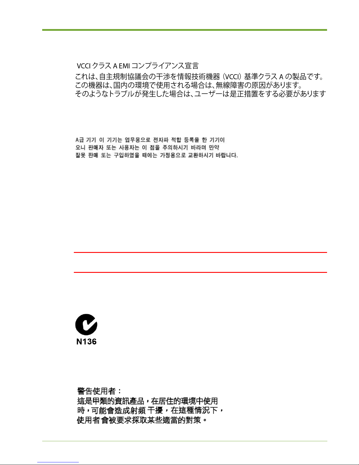
Japan Radio Frequency Interference VCCI
Japan Radio Frequency Interference VCCI
Korea RFI Statement
Canada RFI Statement
This Class A digital apparatus complies with Canadian ICES-003.
Cet appareil numérique de la classe A est conforme à la norme NMB-003 du Canada.
CISPR 22
WARNING! This is a class A product. In a domestic environment, this product may cause radio
interference, in which case, the user may be required to take adequate remedial measures.
Australia C-Tick Label
Taiwan BSMI Statement
535-0045-00 Rev 02 Violin 6000 Series Memory Array Installation Guide 71
Page 76
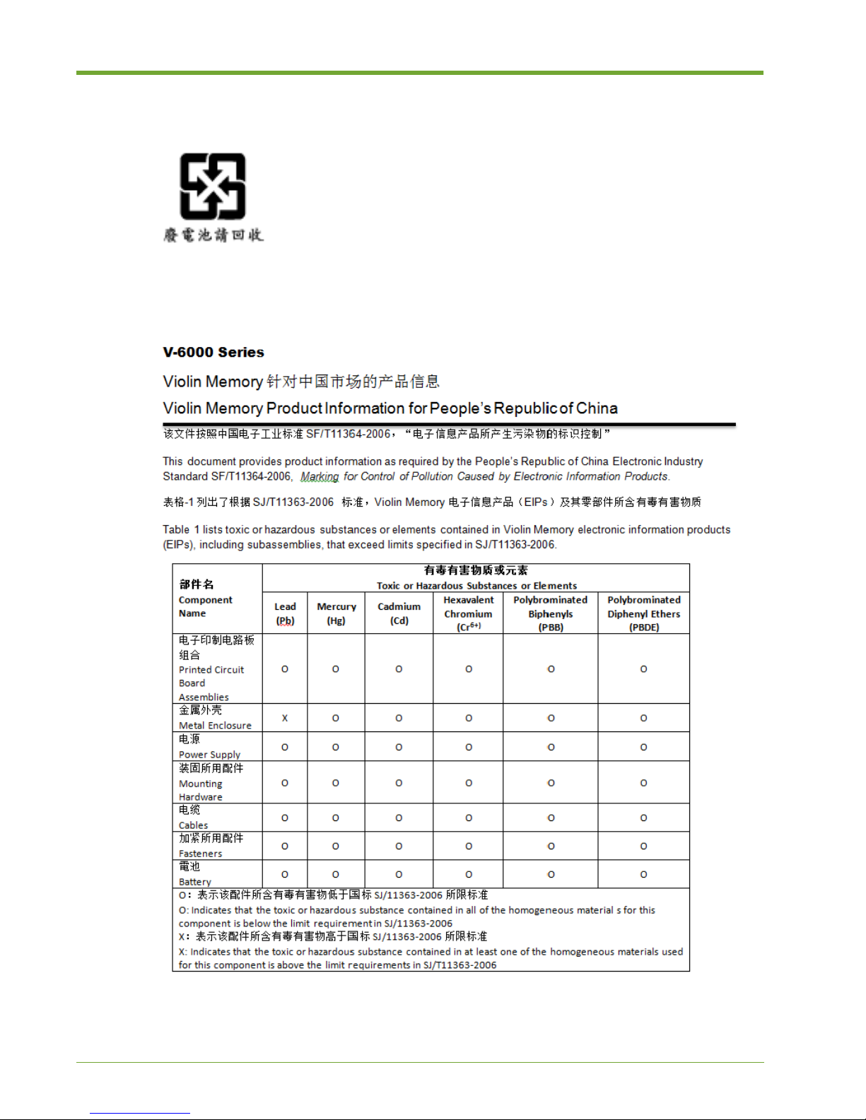
Compliance Information
Four-in-One Recycling Symbol
Product Information for People’s Republic of China
72 Violin 6000 Series Memory Array Installation Guide 535-0045-00 Rev 02
Page 77
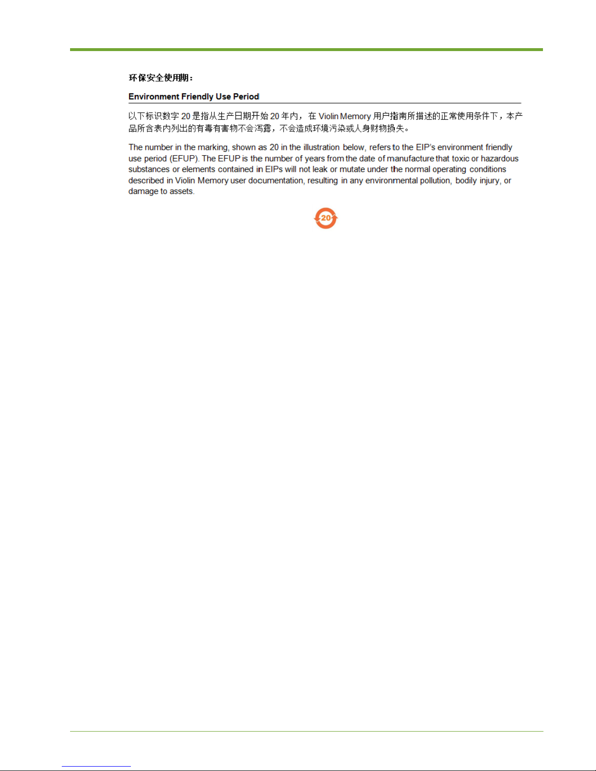
Product Information for People’s Republic of China
535-0045-00 Rev 02 Violin 6000 Series Memory Array Installation Guide 73
Page 78

Compliance Information
74 Violin 6000 Series Memory Array Installation Guide 535-0045-00 Rev 02
Page 79

Index
A
ACM management IP address 38
address
ACM management IP
cluster management VIP
show in CLI 38
asterisk after module ID 38
38
C
cage nuts
installing 18
caution icons 3
chassis
mounting on equipment rack
cluster
cluster management VIP
show in CLI
cluster name
shown in CLI
monitoring 38
number of modules 38
show cluster
show cluster global
show cluster global brief 38
configuration
direct attached
overview 5
configuration wizard
running first time
configuring the system 32
customer support 4
38
38
39
11
33
14–20
D
direct-attached storage 11–13
DM Multipath 55
E
electrostatic discharge
grounding Memory Array 20
equipment racks
installation of chassis on 15–19
Ethernet cable
connecting
Ethernet Interface 62
28
F
fibre channel
connecting cables to Memory Array 24
format
settings
32
I
InfiniBand
connecting cables to Memory Array
interface cables
connecting Memory Array to network
Internal Memory Gateways 9
IP address
ACM management IP
cluster management VIP
show in CLI
38
38
25
23
535-0045-00 Rev 02
Violin 6000 Series Memory Array Installation Guide
75
Page 80

M
management interfaces
serial console port CLI 27
management VIP
show in CLI
Memory Array
configuring
default settings 32
grounding 20
installation
installing in equipment rack 19
mounting on rack 14
powering up 22
securing to equipment rack 29
multipath
client side 2, 55
configuration 56
daemon 59
device mapper 55
setup 56
multipath.conf 56
multipathd 56, 59
38
32–36
attaching to SAN
direct attached 11–14
overview 5
standard configurations 9
9
connecting to Memory Array chassis
power
connecting 21
power supplies
connecting power cords to 21–22
R
rack ears
attaching to chassis 18
S
SAN
SAN-attached storage configurations 9–??
serial cable
connecting 27
show cluster commands
show cluster global
show cluster global brief 38
slide rail kit
package contents 15
39
23–24
N
NIC port numbers
understanding 10
non-transparent bridge
connecting
26
P
PCIe
configuring connection 39
PCIe cable
connecting to ACMs for Data Management
PCIe cables
26
V
Violin 6000
default settings 32
system specifications 62
virtual IP address
cluster management VIP
show in CLI
vMOS-6
cable connection 26
38
W
warning icons 3
wiring
minimum acceptable wire gauge
20
76 Violin 6000 Series Memory Array Installation Guide 535-0045-00 Rev 02
 Loading...