

Page 1

1
User Guide
Hardware and
Windows Client Software
Violet Audio UPM88
Document Control
Author Danny Olesh
Last Print Date 12/8/2005
Version 1.1
File Name UPM 88 Software User Guide.doc
Page 2

2
When it comes to studio applicati ons, ther e is one piece of gear that you just cannot do
without... the patch bay! Over time as you develop your formidable arsenal of equipment,
you will find yourself relying on your audio patchbay more and more. Si m ple p atchbays,
althou gh mess y a nd more difficult to configure quickly than they shoul d be , have pr ovided a
soluti on up until now... but w ith today's tech no lo g y there is a better way.
The UPM 8 8 goes that st ep fu rt he r. .. pure analog signal switching... and digital stream
patching...
The UPM88 is a new breed of patch matrix hardware that represents a very innovative
approach to the marriage of the latest technology and audio signal integrity. It feat ures a
powerful combination of state-of-the-art software and hardware designed to revolutionize the
implementation of small, medium and large-scale audio routing environments by handling
both pure analog signal patching & digital patch routing simultaneously.
Analog patching... pure audio path...
With an absolutely pure audio signal path, remote controlled (USB) routing configuration
features, easy fro nt panel o peration, the UPM88 represents the latest technology in patchbay
design. Whether for complex studio matrix design or a modest patching solution for smaller
setups, the UPM88 is an investment which provides a new level of freedom and flexibility.
Your pure analog audio patching system can be built and controlled from either a simple
front panel switch matrix , or vi a the onscreen compu ter soft ware m atrix GUI (graphical user
interface) via USB connection.
All audio routing through the UPM88 is handled using the latest high-quality analog devices
multiplexer chips available. The audio signal never leaves the analog domain, is not
amplified, or driven in any way, and as such there is no loss of quality as there can be in
som e DSP and AD /DA matrix processing devices. Similar DSP based devices on the market
use digital sampling technology which can degrade signal quality in many ways. The UPM88
has true whisper quiet 'all analog circuitry', and carries the full analog signal between
patchi ng destinations unadulterated. It is the digit a l switching techn o logy in the UPM88 that
is the key.
Digital patch routing...
What about digital? Well... the UPM88 handles digital patching of SPDIF or AES/EBU format
signals perfectly and simultaneously side by side with your pure analog signals! That's
right... not only is the UPM a virtually unmeasurably pure analog patch matr ix, but it is an
astonishingly powerful pro fessional digital patch bay. The best of both worlds in a simple to
operate remotely controlled unit.
Application... operatio n...
Those inevitable momentary design changes which occur in the studio can be solved quickly
and easily with the UPM88. You no longer have to worry about physical patching once your
gear i s c onnected to the rear of t he unit. Y ou can route your audio th r ough a particular pie c e
of outboard gear by simply changing the matrix configuration! No messy cables, rearranging
equip ment in y o ur rack, rewiring. The UP M88 is easily expanded, m o d ified, and upda ted to
accommodate your needs.
Page 3

3
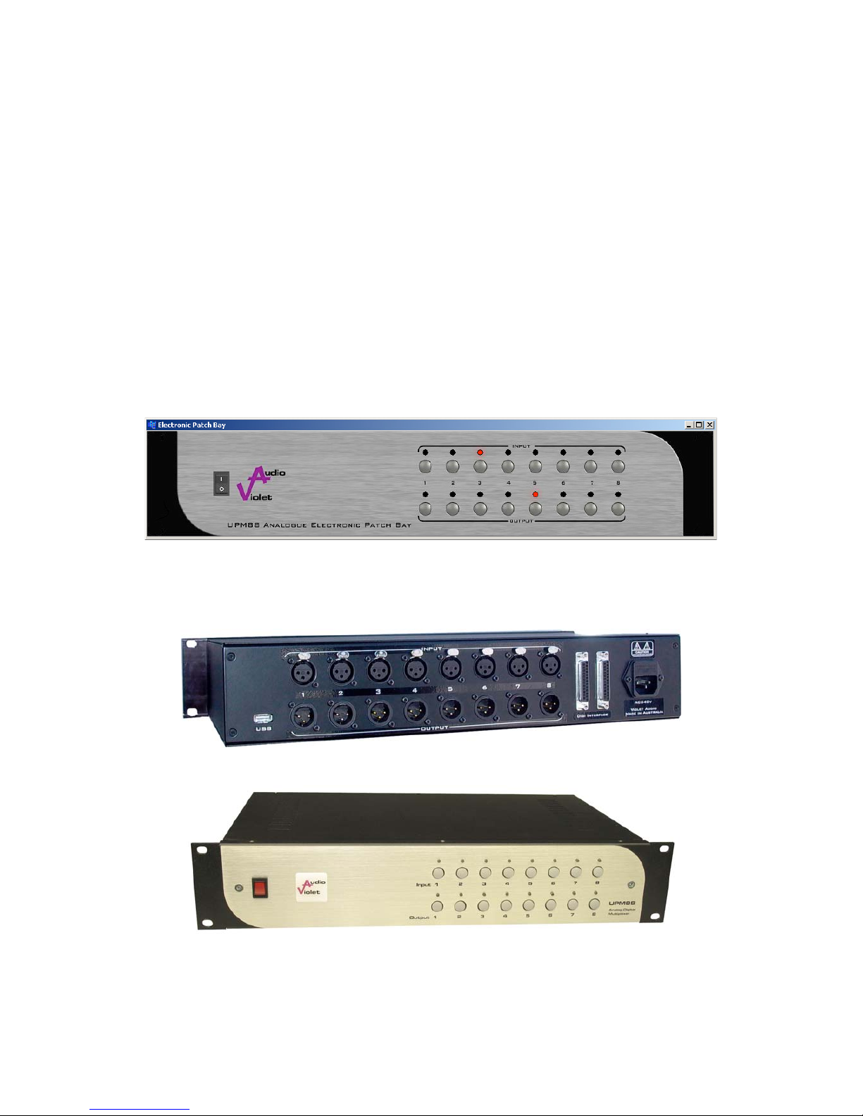
The number of inputs and des tinations starts from 8 x 8 for a single unit, wi th the option to
link 2 units for a 8 x 16 solution. You can keep stacking unit for as many output destinations
as required! The hardware itself is all housed in a purpose built standard 2U sturdy rackmountable chassis. Balanced XLR audio cable connectors are positioned on the rear of the
unit, and thus keep your studio environm e nt super tidy with cabl es out of sight. The fron t
panel features an easy to view led matrix grid indicator with input and destination selector
buttons.
Manually changing the UPM88's matrix configuration is a breeze. The matrix selector buttons
on the front pane l is w here all of the signal routing is confi g ured. Simply select i nput and
destination and o utput destination.. and you are set to go. You can quic kly recognize y our
routin g m a trix by viewing the scrolling configu ration led ' s o n the front of the unit.
With the built in USB port on the rear of the unit, the UPM88 software graphical user
interface can be run within your Windows (av a i l a ble now - 98SE,ME ,2000,XP) or Mac O SX
(expected - 2nd 1/4 2004) operating system. Simply select the inputs on screen and connect
them together with graphical wires to the desired destination output. The UPM88 will
automatically create the desired configuration - actually implementing the system that has
just been designed. You can immediately audi tion the results. Your design can be saved as a
Windows file and you can save and recall as many different designs as required.
As exciting as all of the features of UPM88 are, the most important feature is its sound
quality. Violet Audio is dedicated to providi n g the highest level of sound quality possi ble. The
UPM88 ne eds to be he ard t o be truly appreci ated, as it is t h e sound quality th at we are most
proud of. All audio paths are extremely transparent. The system is unbeliev ably quiet , and
there are no artefacts added to your signal. The UPM88 is purpose built for the demands of
true critical listening
UPM88 Key features
• remotely controlled patch b ay ma trix (USB requir ed)
• passes analog and digital data streams simultaneously
• analog dynamic range greater than 130db
• analog multiplexer technology
• pure analog signal path
• digital switching via front panel or USB
• 8 inp uts, 8 detinations
•
multip le routing sup port (8c h)
•
multiple routin g ou tputs pe r de stination
• pristine audio transparency
• syste m link connector pins (max 2 x units)
• XLR balanced Neutrik connectors (for analog & AES/EBU)
• 2RU rack-mountable chassis
Page 4
4
Table of Contents
DOCUMENT CONTROL ...................................................................................................................................................3
TABLE OF CONTENTS .....................................................................................................................................................4
1. INTRODUCTION ........................................................................................................................................................5
1.1 P
URPOSE ..................................................................................................................................................................5
2. FRONT PANEL............................................................................................................................................................5
3. CHANNELS...................................................................................................................................................................6
3.1 A
DDING....................................................................................................................................................................6
3.2 D
ELETING ................................................................................................................................................................6
3.3 V
ALIDATION............................................................................................................................................................6
4. TROUBLESHOOTING...............................................................................................................................................7
Remedy............................................................................................................................................................................................ 7
Patch Bay Software
Page 5
5
Introduction
1.1 Purpose
The Violet Audio UPM88 is a solid state balanced audio patch bay, which utilizes high quality
analogue multiplexers to route audio signals. A USB interface is provided to remotely change the
routing configuration.
This document describes how to use the Violet Audio UPM88 client software which connects to
the Violet Audio UPM88 unit via the usb interface. It will describe how to add, delete, and verify
channel mappings all via the software interface.
When First switching the UPM88 ON, 2 modes are available. Just switching the unit ON will put
the unit in standard control mode which means that the last display selected is shown. If you
PRESS AND HOLD the INPUT 1 button while switching the UPM88 ON then the unit will
continuously step thru the input and display the relevant outputs on the LED display.
Installing the software:
Copy the ElectronicPatchBay software onto a directory in your hard disk and then copy the USB
driver into the same directory, when you first plug the UPM88 to your USB port the computer will
detect the new USB device and will request a driver, you then select the directory in which you
saved the USB driver and the system will i nsta ll it properly.
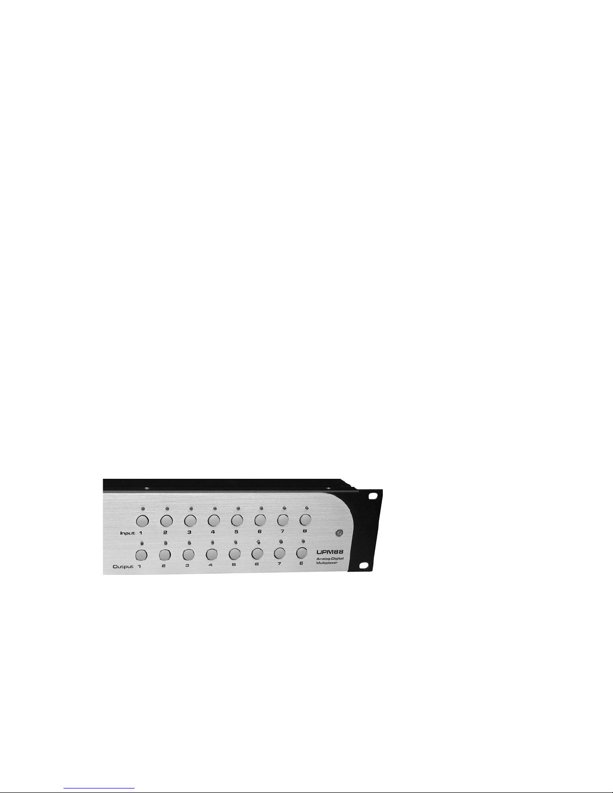
1. Front Panel
The front panel consists of two rows of eight buttons which accurately portrays the front panel of
the actual unit. The top row of buttons represent the eight input channels, and the bottom row
represent the eight output channels. Note that the “power button” can also be clicked to terminate
the program.
The channel buttons can be clicked to route the audio signals from any input channel to one or
more output channels. How this is done is explained in the next section.
2. Channels
When the application starts up it attempts to connect to the actual unit and read the current
channel mapping. If any mappings exist, it then shows them by flashing each of the mappings
one by one, left to right. If no mapping exists then the panel is blank and no lights are lit.
Page 6

6
3.1 Adding
If you wanted to connect input channel 1 to output channels 7 and 8 you would perform the
following steps:
1. Click on input channel 1. Note how the channel 1 light lights up and stays lit. The colour
of the light is Orange. This means you are in “Programming mode”.
2. While you are in programming mode you can add as many output channels as desired.
For now click on output channels 7 and 8. Note how these channels also light up in an
orange colour.
3. Finish programming by clicking on input channel 1 again. This signals to the software that
we are done setting up the channel and the software goes back to flashing each of the
channel mappings. You should now see the newly added channel mapping light up.
Note that the software sends the routing information to the actual unit as you click on them – not
when programming mode finishes.
3.2 Deleting
Deleting a channel is very much like adding one. For example if we wanted to disconnect input
channel from output channel 7 then you would do the following:
1. Click on input channel 1. You will enter “Programming mode”. Note how input channel 1 and
output channels 7 and 8 light up in an orange color.
2. Click on output channel 7. The light will go out and that channel will be disconnected. Note
that as before, this disconnection is immediate – the software sends the instruction to the unit
as soon as you clicked on the channel.
3. Finish programming by clicking on input channel 1.
Note that programming mode will end automatically 5 seconds after the last channel was clicked.
3.3 Validation
To validate the channel mappings you could simply look at the flashing lights as the software
iterates through them. If you find this a little too quick then there are other ways of showing the
channel map.
As you already know, left clicking on any of the input channels puts the software into
“Programming Mode”. If all you want to do is see what is connected to the input channel then
simply right-click on any channel. This will cause the software to stop flashing the other channels
and only show what is mapped to the current channel.
Output channels can be clicked with the left or right mouse button to display the connected input
channels.
Page 7

7
3. Troubleshooting
There are times when the software does not seem to work properly. Following is a list of common
problems and remedies.
Symptom What Happened
Remedy
The unit displays different maps
to what is being displayed on the
software panel.
This can happen if the unit is
programmed at the same time as
the software.
Shutdown the software and
restart it. This will connect to the
unit and refresh the channel
mapping.
The software isn’t
communicating with the unit or
the software has locked up.
If the unit is turned off while the
software is running, then there is
no way the software currently
know this. The next time it tries
to communicate with the unit it
will wait endlessly for the unit to
reply – and the software hangs.
Terminate the application. Turn
the unit back on. Restart the
application.
If the unit cannot be turned back
on but you still want to use the
software then make sure the
USB cable is not plugged in
before starting the software.
UPM 88 DB25 pin-out for multi-channel input and output
 Loading...