

Page 1
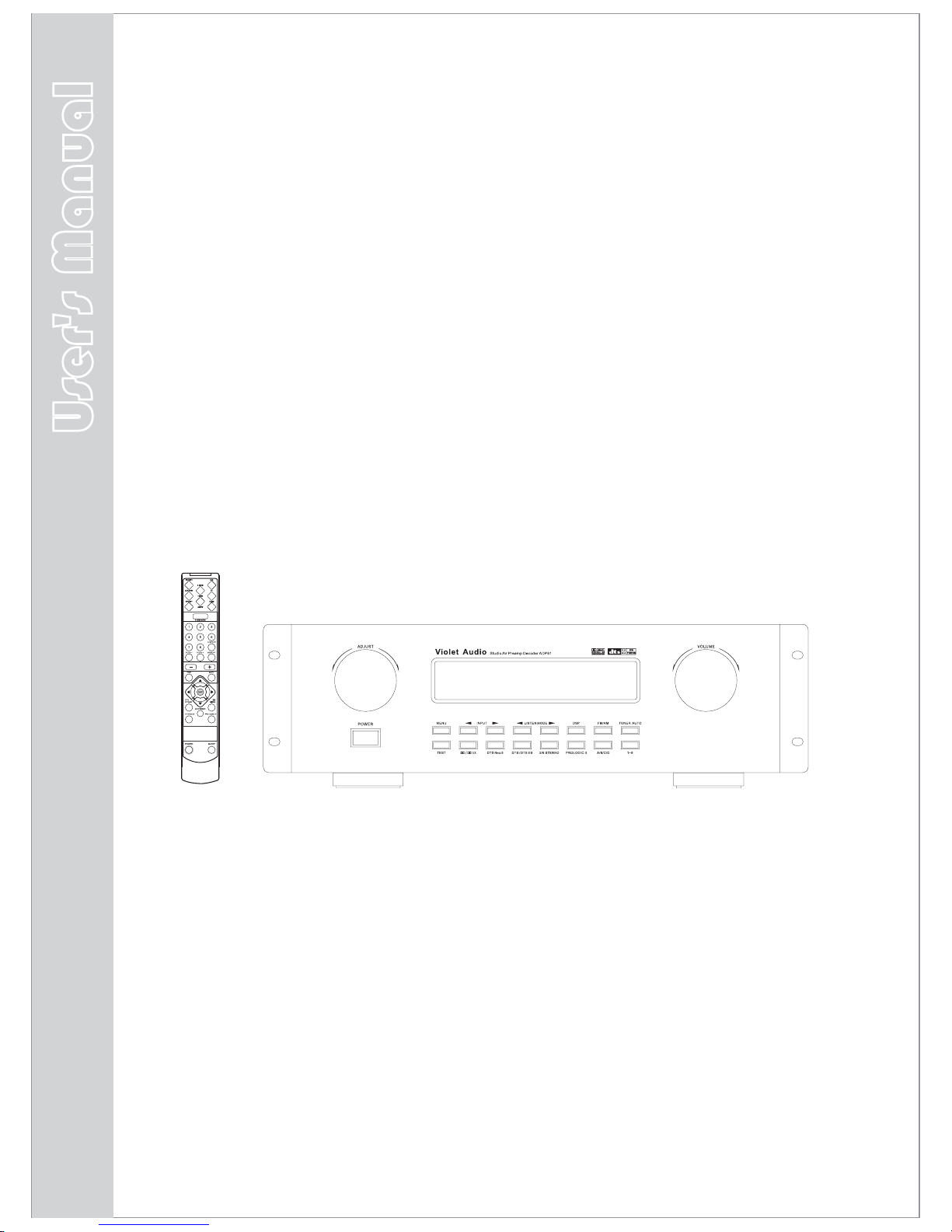
User's Manual V1.3
incorporates software rev.2
ADP61
Violet Audio
Studio AV Preamp Decoder
VOLUME
Violet Audio
Page 2

1
Voltage:
Voltage are 230/120V AC,50/60Hz.
CAUTION: To reduce the risk of electric shock, do
not remove cover (or back). No user-serviceable
parts inside. Please refer all such issues to
qualified service personnel.
CAUTION
RISK OF SHOCK
NOTICE! !NOTICE! !
Thank you very much for purchasing our product.
pleasure
for many years to come
enjoy
Also, k
We sincerely hope it will bring you much
.
In order to optimum performance from this
unit, as well as for matters of personal safety for all
concerned, please read this manual carefully.
eep it in a safe place for future reference.
Explanation of Graphical Symbols
The lightning flash & arrowhead symbol,
within an equilateral triangle, is intended
to alert you to the presence of danger.
The exclamation point within an equilateral triangle is intended to alert you to the
presence of important operating and servicing instructions.
Important Safety Instructions
1. Please read all instructions. All the safety and
operating instructions should be read carefully before
operating this appliance.
2. Store these safety and operating instructions in a safe
place for future reference.
3. Please heed all warnings. All warnings issued in this
manual exist not only to prevent potential damage to
equipment, but also to ensure your personal safety.
4. Follow all instructions. In order to enjoy optimum
performance, please follow all instructions and procedures.
5. Do not use this apparatus near water.
6. Remove any dust by using dry cloth or brush.
If more thorough cleaning is necessary, use damp cloth
(in this event, please disconnect unit from AC outlet).
7. Do not block ventilation openings. Proper airflow is
essential for optimum operation.
8. Keep unit away from heat sources such as radiators,
stoves, ovens, heating ducts and devices (including
amplifiers) that can potentially produce heat.
9. Do not tamper with the
AC (power) lead. If the plug
provided does not fit your power outlet, consult qualified
service personnel or electrician for a suitable solution.
Also, never use a damaged AC lead, for any purpose!
10. Ta k e measures to protect AC power lead from being
walked on, crushed, twisted, cut or pinched. Exposed
core is highly dangerous if plugged into AC outlet.
11. Only use attachments and accessories as specified
by the manufacturer. Never force connectors!
12. Avoi d over-stacking equipment. Stacking more than
two units can become unsafe for equipment and operator
alike. Use only with a cart, stand, mounting brackets or
table specified
by your supplier, or specifically sold with
the apparatus. Please secure firmly if using a trolley or cart.
WARNING
To reduce the risk of fire or electric shock, do not
expose this unit to rain or moisture.
PLEASE FOLLOW THESE STEPS:
PLEASE REGISTER YOUR PRODUCT ON
www.violetaudio.com
Continues overleaf
Page 3

2
Setup and Maintenance of the Receiver
Do not connect to the AC outlet until all other
connections have been completed.
Do not use your receiver immediately after transferring it
from a cold environment to warm. This action may result
in a build up of condensation inside the unit.
Do not expose your receiver to water or excessively high
temperatures.
After having disconnected your receiver, clean the case
with a soft cloth, or with a slightly damp leather chamois.
Never use strong solvents.
Should connectors show build up of contaminants
over a period of time, in order to ensure optimum
performance, clean contacts with appropriate
cleaning agents. Consult your dealer or qualified
service personnel
Protect Your Receiver From Overheating
Do not block ventilation holes
.
any or cover unit with
materials that impede air flow, such as other equipment,
cartons and fabrics etc
Arrange receiver so that air can circulate freely.the
If stacking is absolutely necessary, please allow for
proper air flow between units.
If mounting on a stand or into a 19” EIU equipment rack,
please provide adequate ventilation and spacing with
adjacent units.
Place high heat emitting devices such as
power-amplifiers and satellite receivers away
from receiver and other sensitive components.
To prevent overheating, please provide
sufficient ventilation.
15. Cleaning - Unplug this unit from the wall outlet before cle-
aning. Do not apply spray, aerosols or liquid cleaners directly
onto chassis. If necessary, use only a slightly damp cloth.
16. External antenna - if used with an external antenna, take
care to locate the antenna away from power lines.
17. Accidental object and liquid entry - Care should be taken
so as to prevent foreign objects or liquids entering the enclosure.
Should this occur, detach power cord immediately and refer
unit to qualified service personnel. Do not attempt to power up
again until approved by said personnel.
18. If you have
any doubts as to the safe operation or optimum
performance of this unit, please consult your retailer or
qualified service personnel.
13. Unplug receiver during lightning storms or if unused
for long periods of time.
14. All servicing issues should be referred on to qualified
personnel, especially should the apparatus not
operate
in a normal manner. It is also highly recommended should
the unit be exposed to rain or be subjected to liquid spills,
objects falling inside or suffer physical damage to chassis,
power-supply cord or plug.
Important Safety Instructions
Page 4

Table of Content
3
Features
4
Fittings
Installing batteries in the remote controller
Notes About the Remote Control
Remote control operation range
Connecting to Audio-Visual Components
Digital Connections
Connecting the Antenna
AM Loop Antenna and FM Indoor Antenna
Connecting for Power
Connecting Power Amplifiers
or Powered Speakers
Positioning your speakers
Preferred surround placement
Alternative Surround Placement
5
6
6
6
7
8
9
9
9
10
11
12
12
Getting Started ADP61
5
Operating Your ADP61
Panel introduction
The Remote Control
Remote Control Functions
Rear Panel Introduction
Display
Default Window Display Information
Power on / off / standby
Last State Memory
Tone Adjustment
Output Level Adjustment
Speaker
Sleep Function
Display Brightness Adjustment
Tuner Memory Operation
Retrieving Preset Stations
25-pin D-SUB Input
Speaker Settings (Speaker Mode)
Level Calibration
Input Source Selection
Input Source Reference Level Adjustment
Synchro Audio/Video Sources
Audio Format Recognition
Listen Mode Display
Tuner Functions
11
13
14
15
17
17
18
18
18
19
22
24
25
25
25
26
26
26
26
27
28
29
29
11
2 Stereo
6 Stereo
Dolby Pro Logic II Movie
Dolby Pro Logic II Music
Dolby Digital
Dolby Digital SurroundEX
DTS
DTS 96/24
DTS-ES Discrete
DTS-ES Matrix
Neo:6
30
30
30
30
30
30
31
31
31
31
31
About the Listening Modes
30
Sound Enhancement Systems
32
32
32
32
33
33
33
33
Dolby Pro Logic
Dolby Digital and Dolby Digital Surround EX
2/6 Channel Stereo
DSP(Digital Sound Field Processor)
DTS Neo:6
DTS/DTS ES
DTS 96/24
Adjusting the DTS,Dolby Digital LFE Level
Dynamic Range(Night Mode)
Adjusting the Delay Tim e
Adjusting the Parameter Settings for Pro
logic II MUSIC
34
34
35
35
Advanced Sound Control
30
36
39
39
Troubleshooting
36
General
Tuner
Remote Control
40
40
40
Other
40
Resetting Factory Presets
Abbreviation of the monitor and full
working name
Available Selection All Listening Modes
41
Specifications
Table of Content
3
Page 5

Digital Sound-field Processing multi-mode
Other Features
Main Features:
4
Dolby Digital Decoder
DTS Decoder
Dolby Digital Surround EX Decoder
DTS 96/24 Decoder
DTS ES Discrete Decoder
DTS-ES Matrix Decoder
DTS Neo:6 Cinema
DTS Neo:6 Music
Dolby Pro Logic II Movie
Dolby Pro Logic II Music
6 CH Stereo Mode
2 CH Stereo Bypass Mode
8 DSP modes: Live, Cinema, Disco, Stadium, Jazz,
Church, Hall
& Pro Logic
Manufactured under license from Dolby Laboratories.
"Dolby", Pro Logic", "Surround EX" and the double-D symbol
are trademarks of Dolby Laboratories.
DTS, and DTS ES ,Neo:6 and DTS 96/24 are
trademarks of Digital Theater Systems, Inc.
Up to 24-bit/192khz playback via digital inputs
High-resolution D/A converters
DSP effects, including surround (see DSP modes above)
Operation from front panel or IR remote control
Adjustable sub woofer x-over frequency
Adjustable Reference Volume for each input section (0-15db)
Enhanced Audio Features
Automatic Audio Format Recognition
Source Format Display
Bass Management system, Full Digital
Level individual
Pink Noise Generator for line and speaker test
Treble & Bass
Digital AM/FM tuner
64 Auto Memory Presets (AM/FM separate)
Quartz PLL Synthesized Digital Tuning system
Manual Tuning
Sleep Timer
, DSP
Fully functional remote control
Remote control standby
balanced XLR outputs
7 individual output level and on/off controls
1 analog stereo line output (pre volume-control)
1 digital coaxial input
1 AES/EBU input via XLR
4 S-video inputs, 1 S-video output
4 composite video inputs
1 composite video out
Sub-woofer x-over trim pot (50hz - 150hz)
Adjustable Reference for each
input section (0db to
-15db)
trim pots (for FL & FR channels only)
Last State Memory, including routing and decode settings
7
2 XLR balanced inputs with pad switch (+4db, 0db & -10db)
1 digital optical input via TosLink
25-pin D-sub input connector (6-channels +4db bal.)
Page 6
5
Getting Started ADP61
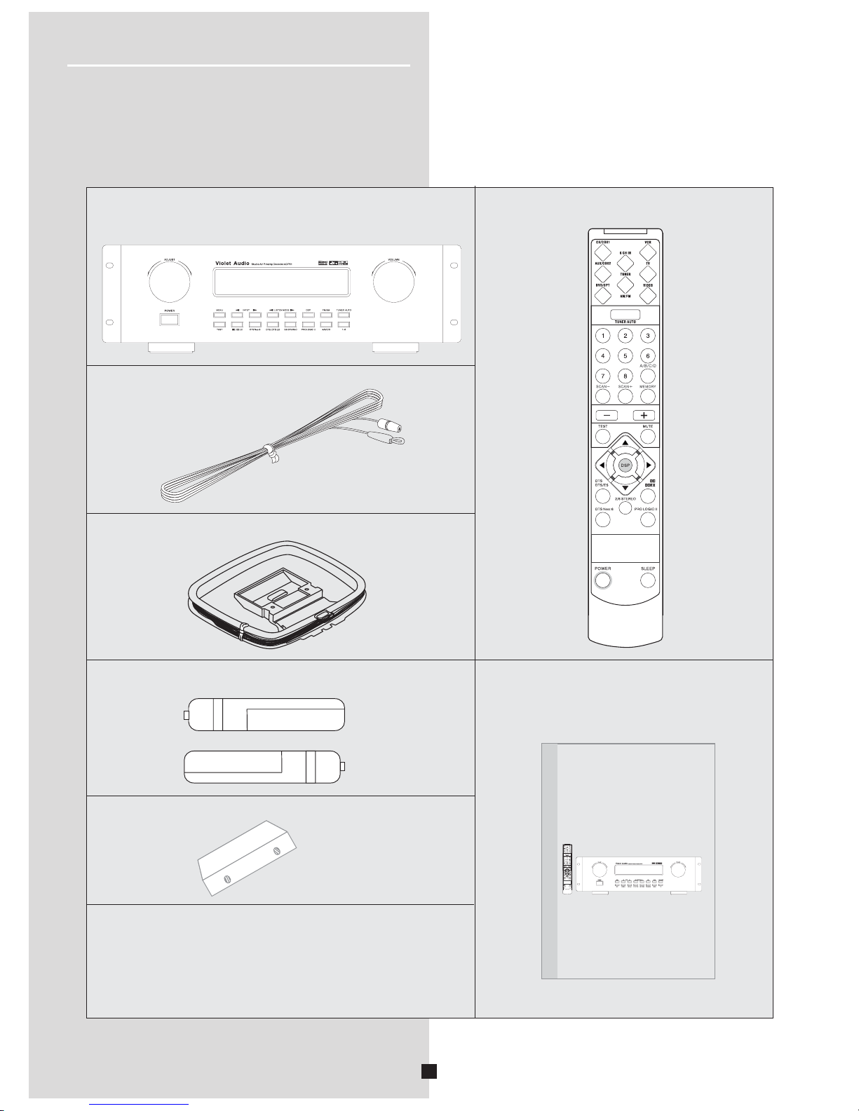
You should receive the following items:
Fittings
One instruction manual
Indoor FM antenna
AM loop antenna
2 x 19” EIU Rack Adaptors
One ADP61 unit
One Remote Control
AAA,R3P,UM-4 batteries
Warranty Information:
Please fill online warranty card
on www.violetaudio.com
AAA,R3P,UM-4 batteries
AAA,R3P,UM-4 batteries
VOLUME
User's Manual V1.2
ADP61
Violet Audio
Studio AV Preamp Decoder
User's Manual
VOLUME
Page 7
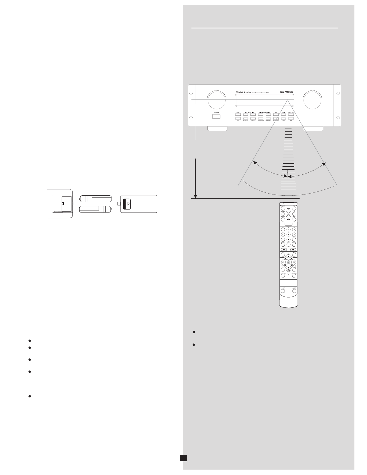
Notes About the Remote Control
Should you find the remote controls response gradually
decreasing in range, the batteries are most probably reaching
the end of their life. Replace both batteries with new ones,
preferably of matching brand and type.
Remote Control Operation Range
The area between the remote control and the main unit must be
clear of large obstacles.
Do not expose the remote control sensor to strong lighting,in
particular an inverter type fluorescent lamp.Otherwise,the
remote control may not work
properly. If necessary, position the
main unit away from direct lighting.
¡30
30¡
Within approximately
6m(19.7feet)
6
Battery Replacement
Notes
Notes
Since the remote control will be used for many of this unit's
control operations, you should begin by installing the supplied
batteries.
1.Turn the remote control over and slide the battery compartm-
ent cover in the direction of the arrow.
2. Insert the batteries(AAA,R03P,UM-4 TYPE) according to the
polarity
markings on the inside of the battery compartment.
3.Close the battery compartment cover.
Use AAA,R3P,UM-4 batteries.
Be sure the batteries are correctly oriented according to polarity.
(See the illustration inside the battery compartment.)
Remove the batteries if the remote control is not used for an
extended period of time.
Should any battery leak,
dispose of it immediately.
Avoid physical contact of leaked material with skin or clothing
etc. Clean compartment thoroughly before installing new
batteries. If in doubt, consult your dealer or service personnel.
Never dispose of batteries in a furnace or open fire.
Exposure
to extreme heat or fire may result in an explosion
and cause possible injury!
Installing batteries in the remote controller
VOLUME
Getting Started ADP61
Page 8
AC INLET
240V~50Hz 30W TIA 250V
7
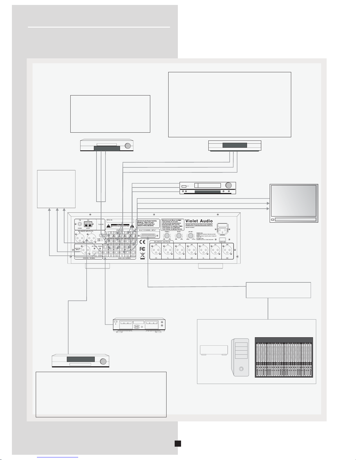
Connecting to Audio-Visual Components
If you have a LD player, DVD player or CD player with a digital output, you can make use of an
optical digital cable (not supplied) or coaxial digital cable (not supplied) to carry the audio portion
of the signal and enjoy Dolby Digital sound quality.
One optical or coaxial cable is needed for each LD player, DVD player or CD player. This
receiver provides one optical, one coaxial and one XLR digital input for the connection of your
components. Please connect your components (e.g. LD, DVD, or CD) to the appropriate digital
inputs and press INPUT button to select your connection.
Note:
Optical and coax cables carry only the audio portion of the signal. A separate video connection
must also be established for a LD player and DVD player. S-video provides the best connection
for the video portion of the signal. Composite video (yellow RCA connector) can also be used. It is
important to use the same connection type (S-video or composite) to connect the LD or DVD
player to the ADP-61 and then from the ADP-61 to the TV, LCD or Plasma display.
199
Connect components
capable of outputting Dolby
Digital (e.g. DVD or LD) or
standard PCM(CD) format
digital signals. Read section
on "Digital Connections"
under "Getting Started".
CD Player
Digital Workstation
Tape Deck
VCR
DVD
LD
TV
AUDIO OUT Balanced
To AUDIO OUT (DVD)
To VIDEO OUT (DVD)
To S-VIDEO OUT (DVD)
To VIDEO OUT (VIDEO)
To AUDIO OUT(VIDEO)
To S-VIDEO OUT (VIDEO)
To AUDIO OUT(VCR)
To VIDEO OUT (VCR)
To S-VIDEO OUT (VCR)
To VIDEO IN (TV)
To AUDIO OUT (TV)
To S-VIDEO IN (TV)
Unit
Rear Panel
If your CD or DVD player is equipped with digital output jacks, you can enjoy superior sound quality
by making use of them.
S/PDIF Digital connections are possible via either a TOSLINK optical or a 75ohm co-axial cable with
RCA connectors. For a AES/EBU connection, a 105ohm digital XLR cable is required.
Once connected, simply select either Coax-1, Coax-2 or OPTICAL input for each connection.
Note: This receiver only has one of each digital input type. Yo u may have to use the optical for one unit,
while using the co-axial connection for another.
Also note: Digital cable quality will affect performance. To minimize jitter and other artifacts, only use
good quality, well shielded digital cables.
If your video component has a S-Video output connection,
you can enjoy enhanced video quality by connecting it to
one of the S-Video input sockets on the rear panel of the
ADP-61.
One video cable is needed for each component.
Note: Before plugging in any optical or S-Video cable, make
sure the shape or pin configuration of the plug and socket
match. Be careful not to apply excessive force when making
a connection!
25-pin D-Sub connection for 6 analog channels
i.e. Digidesign, Tascam, Mackie etc.
(+4db balanced) For details see p.29
menu
menu
Getting Started ADP61
Mul ti-form at player/
Extern al decoder
DIGITAL AUDIO
WORKSTATION
MIXING CONSOLE
Page 9
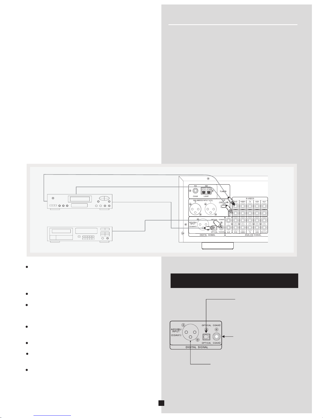
Digital Connections
8
The corresponding video and
s-video input jack is: “DVD”.
The corresponding video and
s-video input is: “VIDEO”.
The corresponding video and
s-video input jack is: “TV”.
HINT
When hooking up an A/V unit, such as a VCR, make sure
to connect to all necessary terminals to the same name,
i.e. S-video or composite video as well as the 2xRCA analog
to all relevant sockets labelled “VCR”. The digital terminals also
correlate with certain video sockets (see HINT
in next column)
Be sure to attach the dust covers when the OPTICAL terminals
are not being used. This prevents contamination by dust etc.
For accurate DTS-decoding, the DTS bitstream integrity must
never become compromised. Incorrect or poor quality cables
and connectors can corrupt the bitstream and degrade
performance.
In order to
prevent digital errors and enjoy optimal
performance, please use dedicated, good quality digital
cables.
For S/PDIF: 70ohm digital co-axial or TosLink optical.
For AES/EBU: 110ohm balanced digital co-axial cable.
All digital audio signal input terminals accept the following
sample rate frequencies: 32 kHz, 44.1kHz, 48kHz, 96kHz
& 192kHz.
Quality of digital cables
and connectors do have a bearing
on sound quality and performance. Keep cable lengths to
a minimum.
If your CD, LD, DVD, TV/satellite tuner or DAW etc, are
equipped with a either coaxial, optical or AES/EBU XLR
digital output terminals, you can take advantage of this
sonically superior connectivity by utilizing the corresponding
input sockets on the ADP61's rear panel
Digital audio signals are not prone to the
same type of signal
loss and distortion factors as observed with typical analog
connections. Digital connections are especially recommended
when decoding multi-channel surround information, such as
Dolby Digital and DTS from LD, DVD, CD players, and
other digital sources.
To make an optical digital connection between this unit and an
external unit, remove the cover from each optical terminal, and
then connect them by using a commercially available optical
fiber cable that conforms to EIAJ standards.Other cables might
not function correctly.
Even if you connect an audio/video unit to the OPTICAL (or
COAXIAL) terminal of this unit, you must keep the
unit connec-
ted with the same named analog audio signal terminals of this
unit, because digital signal cannot be recorded by a tape deck
or VCR connected to this unit. Yo u can switch the selection of
input signals between digital and analog easily.
DVD
CD
COAXIAL OUT
OPTICAL OUT
S-VIDEO OUT
VIDEO OUT
Notes
Getting Started ADP61
Page 10
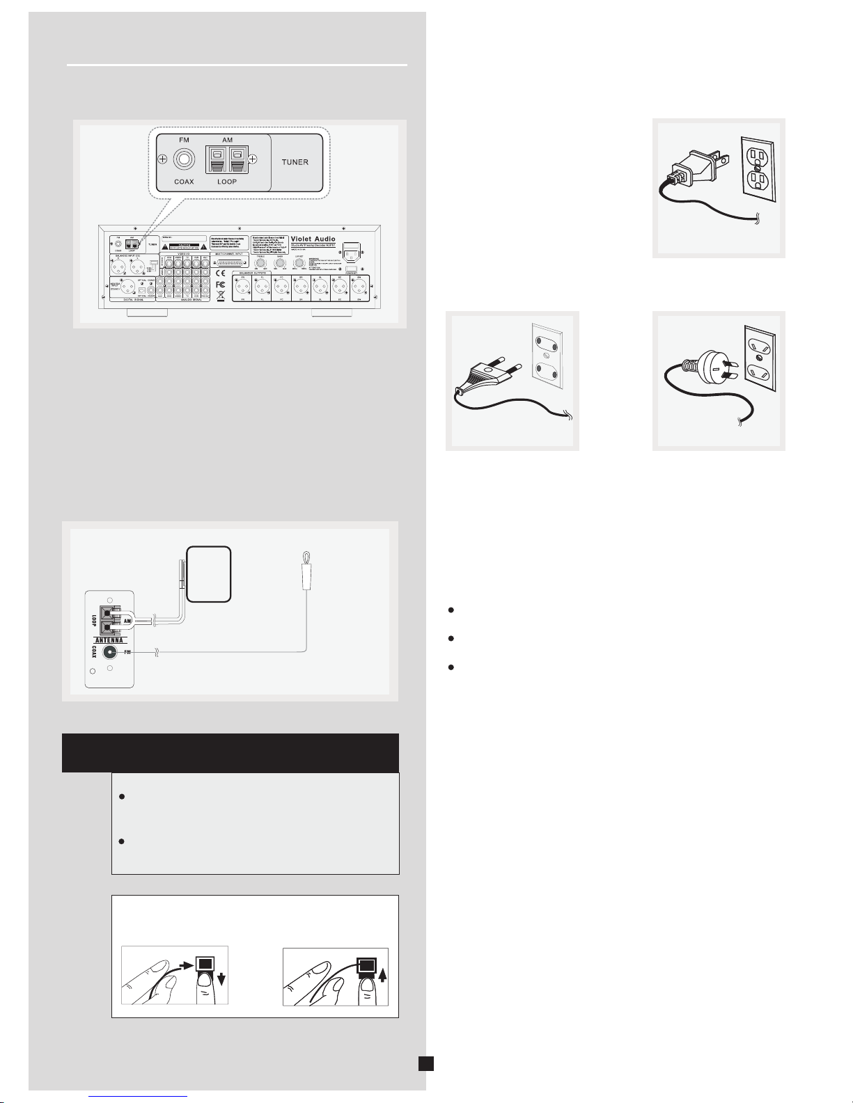
AM Loop Antenna and FM Indoor Antenna
1.
2.
Uncoil the Antenna wire.
Press down on the Antenna tab to open the terminal.
Connecting the Antenna
The AM and FM antennae connect to the top left section
of the rear panel of the ADP-61.
They must be hooked up in order to receive clear reception.
HINT
For best FM reception, extend antenna to its
full length and position at highest possible
elevation.
For AM, rotate the antenna horizontally
for optimum reception.
1.
2.
AM Antenna
wire Connection
Connecting for Power
Make sure you connect up all your
other electronic components and
the speakers before plugging your
receiver into the outlet. Plug the
power cord in the wall outlet,
matching the wide blades of the
plug with the wide slots of the outlet.
Be sure to insert the plug
completely.
Notes:
Do not play audio at a high volume. Hearing experts
advise against continuous extended play.
If you experience a ringing in your ears, reduce volume or
discontinue use.
Always turn down the volume before connecting your speakers
.
9
Getting Started ADP61
AC INLET
240V~50Hz 30W TIA 250V
US power plug
European power plug Australian power plug
Page 11

AC IN LET
240V~50Hz 30W TIA 250V
10
SUB WOOFER
SURROUND RIGHT
SPEAKER
FRONT CENTER
SPEAKER
FRONT RIGHT
SPEAKER
RIGHT
LEFT
RIGHT
LEFT
SURROUND CENTRE
SPEAKER
Connecting Power Amplifiers.
If you are using Powered Speakers, simply connect directly to ADP61 corresponding XLR outputs
SURROUND LEFT
SPEAKER
FRONT LEFT
SPEAKER
POWER
0
1
2
3
5
6
7
8
9
10
4
0
1
2
3
5
6
7
8
9
10
4
Professional Power Amplifier
Dc&Temp
Clip
Signal
Power(Bridge )
POWER
0
1
2
3
5
6
7
8
9
10
4
0
1
2
3
5
6
7
8
9
10
4
Professional Power Amplifier
Dc&Temp
Clip
Signal
Power(Bridge )
POWER
0
1
2
3
5
6
7
8
9
10
4
0
1
2
3
5
6
7
8
9
10
4
Professional Power Amplifier
Dc&Temp
Clip
Signal
Power(Bridge )
POWER
0
1
2
3
5
6
7
8
9
10
4
0
1
2
3
5
6
7
8
9
10
4
Professional Power Amplifier
Dc&Temp
Clip
Signal
Power(Bridge )
Getting Started ADP61
Page 12
1
2
3
9
4
5
7 10
12
13
14
15 16 17
20
11
8
6
18 19
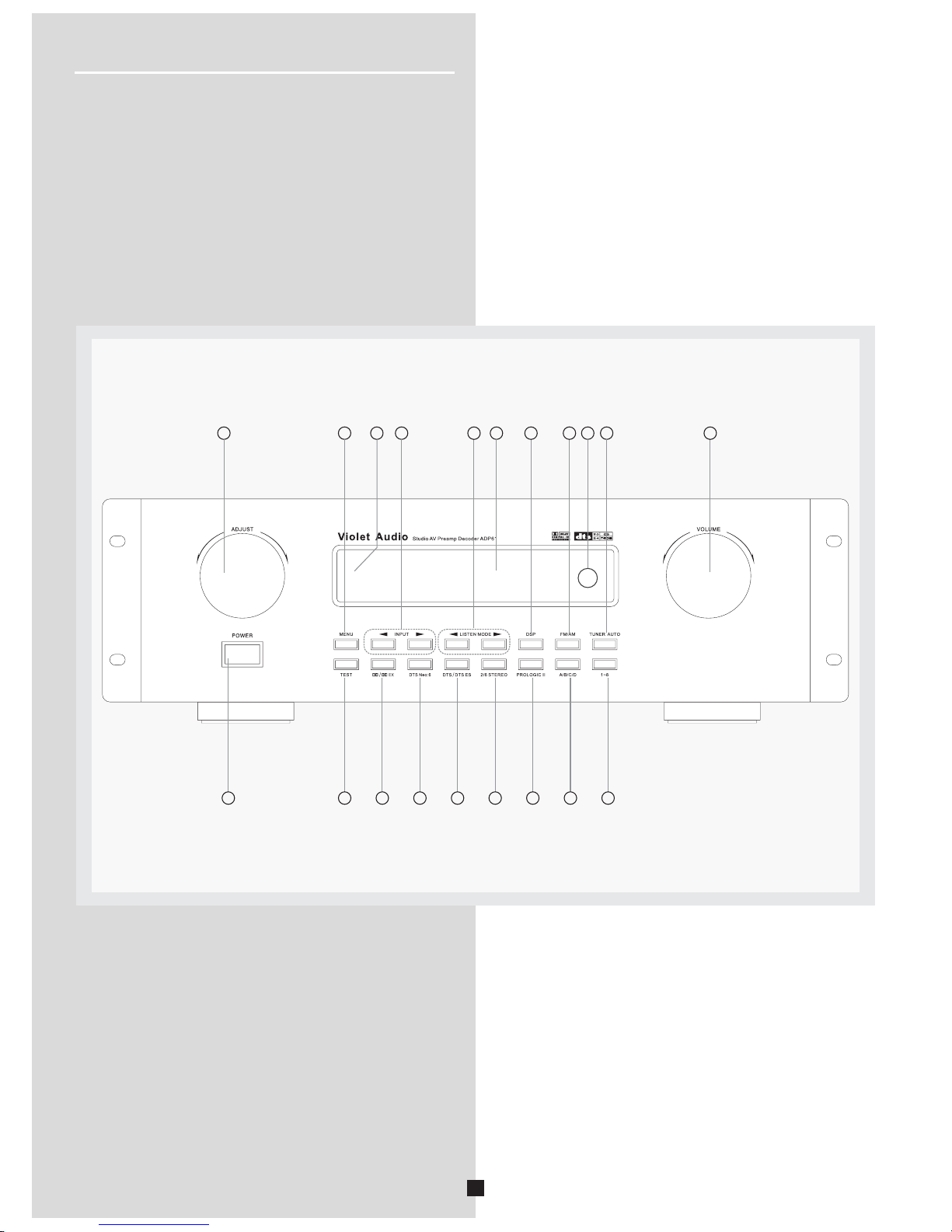
Operating Your ADP61
Panel Introduction
11
Page 13

12
Surround, Center, Subwoofer.
Clockwise rotation increases volume, while anti-clockwise
reduces it.
POWER switch
Press this switch to turn on the power. Press the switch again
to turn off. Note: Power ON defaults to Standby mode.
13. TEST
Sends Pink Noise test tone sequentially to each analog output.
This enables you to balance output channel levels as well as test
your amplifier and speaker connections.
Also performs Reset function. See page 40 "Resetting Factory
Presets".
14.Dolby Digital & Dolby Digital Surround EX mode
Note:
15.
16.
Note: Input sources must be DTS or DTS ES
17. 2/6 STEREO
Selects playback of standard 2-channel stereo mode
(BYPASS) or splits signal into 6 channels (3 x stereo)
18.
19. A/B/C/D
Selects one of the 4 preset station groups (A to D) when the
unit is in tuner mode.
20.
12.
-encoded.
selection button.
DTS Neo:6 Cinema/Music mode selection button
DTS & DTS ES mode selection button.
PROLOGIC II.
Select between Cinema and Music mode for surround
enhancement of stereo source or decoding of Dolby
encoded video tape or LD.
Number 1-8 button
Press these buttons to select preset tuning channel.
Operating You r ADP61
Input sources must be Dolby Digital or Dolby Digital Surround
EX-encoded.
1.ADJUST
This control enables you to adjust individual parameter values,
with the exception of the master volume.
.
4 INPUT selector
Enables the selection of
LISTEN MODE
Enables the selection of preferred output modes
7.
Live, Cinema, Disco, Stadium, Jazz, Church,
Hall and ProLogic.
8.
Note:
Default parameter is REF (Reference Level for currently
selected input).
2.Standby indicator
Lights up when unit is in standby mode.
3 MENU selector button
Press the button repeatedly to scroll through the parameter
MENU of the current output mode. Use the "ADJUST " knob
to edit parameter value.
.
input sources.
5.
.
Note:
Dolby Digital and DTS modes only available when receiving
from external digital source. I.e. DVD player etc.
6. Display window
Displays a variety of information. e.g. Volume levels, DSP,
currently active input source, listening mode and individual
parameter values etc.
DSP mode
Selects between eight artificial acoustic surround
environments:
FM/AM
Selects either the FM or AM radio bands.
9.Remote control sensor
Receives signals from the remote control.
10.TUNER AUTO automatic radio tuning button
Hold down the button for more than 3 seconds to start automa-
tic preset tuning (AM/FM have separate memory banks).
11.Master VOLUME control
Simultaneously controls volume for all output sounds; Front,
Page 14

VOLUME
Operating Your
ADP61
Your Remote Control
Please be sure you have inserted the batteries into the remote
control.
13
1
4
5
6
7
8
9
10
11
12
13
14
15
16
17
18
1
2
3
Page 15

Operating Your
ADP61
Remote Control Function
1. I selector section
2.
3. Numerical keypad (from 1-8)
Press these buttons to select preset tuning channel.
4. Tuning scan buttons
5.
6. TEST
Activates Pink Noise test tones to each output sequentially.
7. S
8. DTS & DTS ES mode selection button
9.DTS Neo:6 Cinema/Music mode selection button
10. POWER
Alternates between Power On and Standby Mode.
For this button to function, first make sure the POWER
switch is depressed on the ADP-61’s main panel and
that the red standby light is on.
11.A/B/C/D
nput
Selects the input source you want to listen to or watch.
TUNER automatically tuning button
Hold down the button for more than 3 seconds to start automa-
tic preset tuning (AM/FM is detached).
Press the SCAN+ side to tune in to a higher Frequency.
Press the SCAN- side to tune in to a lower frequency. Press
and hold for two seconds to scan automatically.
Master volume
ET MAIN MENU button
Press these buttons to turn the unit into the SET MAIN
MENU mode.
Scroll to the desired parameter by using the L or R buttons,
then press the + or - buttons to adjust value.
Note:
Input sources must be DTS or DTS ES
Controls the level of all seven XLR output channels.
-encoded.
Selects one of the 4 preset station groups (A to D), when
the unit is in tuner mode.
12. Stores a station in the memory
13. MUTE
Mutes the sound. Press again to restore the audio out to the
previous volume level.
14. DSP mode selection button
Eight DSP modes: Live, Cinema, Disco, Stadium, Jazz,
Church, Hall, and ProLogic.
15. Dolby Digital & Dolby Digital Surround EX mode
selection button
Note:
16. 2 channels stereo mode & 6 channels stereo
mode selection button
17. Dolby Pro logic II Movie/Music mode selection
button
18. SLEEP button
Sets the sleep time:10min,20min,30min,40min, 50min,60min,
70min,80min,90min,100min,110min,120min.
Input sources must be Dolby digital or Dolby Digital Surround
EX-encoded.
14
Page 16

AC INLET
240V~50Hz 30W TIA 250V
Rear Panel Introduction (note.. Current model has Treble and Bass Control on the rear Panel)
15
Operating Your
ADP61
1 2 3 4 5 6 7 8 9 10
11 1312 14 1918171615 21 22 23 24 25 26 27
28 29 30 20
Page 17

Operating Your
ADP61
1.CD or DAW Balanced input jacks
2..FM antenna input
3.AM antenna input
4.CD input gain switch
5.Video input jacks
Note: using corresponding analog audio jack.
6.S-Video input jacks
Note: using corresponding analog audio jack.
7.S-Video output jack
8.Video output jack
9.25-pin D-sub balanced 6-channel input
10.AC ~220/240V 50/60Hz power input plug
11.Digital AES/EBU. XLR input jack
12.Digital coaxial input jack
Note:
13.Digital optical input jack
Note:
14.AUX Analog Audio input jacks
15.DVD Analog Audio input jacks
16.VIDEO Analog Audio input jacks
17.TV Analog Audio input jacks
18.VCR Analog Audio input jacks
19.PRE Analog Audio output jacks
20.Voltage:AC 230V 50/60Hz
AC 115V 50/60Hz
21.Front Right Balanced output
22..Front Left Balanced output
23.Front Center Balanced output
24.Surround Right Balanced output
25.Surround Left Balanced output
26.Surround Center Balanced output
27.Subwoofer Balanced output
28. TREBLE control
Affects only Front Left and Front Right outputs
29. BASS control
Affects only Front Left and Front Right outputs
30. LSF SET
Adjusts the low-pass frequency point for the
sub-woofer channel. Adjustable from 50Hz to 150Hz
Corresponds with the DVD input socket group,
including Composite Video and S-Video.
Note:
Corresponds with the TV input socket group,
including Composite Video and S-Video.
Corresponds with the VIDEO input socket group,
including Composite Video and S-Video.
16
Page 18

Operating Your ADP61
Display
1.DOLBY DIGITAL/DIGITAL.EX/PRO LOGIC II
Lights up when a Dolby Digital signal is received.
Lights up when a Dolby Digital EX signal is received.
Lights up when Dolby Pro logic II mode is selected.
2.DTS DIGITAL SURROUND
Lights up when a DTS signal is received.
3.DTS ES
Lights up when a DTS ES signal is received.
4.DSP
Lights up when DSP mode has been activated.
5.
Blinks to show that a station can be stored.
6.STEREO
lights up when a sufficiently strong FM
stereo broadcast signal is received.
7.TUNED
Lights up to indicate correct tuning to a station.
8.INPUT SOURCE INDICATOR
MEMORY
Shows which input
source is currently active.
TUNED
CD
AUX
TUNER
VIDEO
TV
VCR
DVD
6CH
MEMORY
1 2 3 4 5 6 87
9
9. Speaker Configuration Indicator
Shows all currently active speaker outputs.
FL:Front Left channel
FC:Front Center channel
FR:Front Right channel
LFE:Subwoofer channel
SL:Surround left channel
SC:Surround center channel
SR:Surround right channel
MUTE: Blinks when the MUTE function is on.
17
TUNED
AUX
TAPE
TUNER
VIDEO
TV
VCR
DVD
6CH
MEMORY
Default window display information (software rev.2 only)
1. Current output configuration
2. Currently selected input source
3. Input source Reference Level
4. Master Volume setting
5 Additional input selection options
During typical operation, once a function has been selected
or a parameter value changed, the display window will
automatically revert
to this default display mode after 5 seconds.
1. 2.
3.
4.
5.
Page 19

Switching On / Off
Operating Your ADP61
In order to get started, we need to be in Standby mode. For
this to happen, make sure the POWER switch on the panel is
pressed in. A red indicator light will confirm Standby mode on
the display panel.
Now, either press any of the 16 buttons on the front panel
of
the ADP61 or the STANDBY button on the remote control.
You should now see the message VIOLET AUDIO scroll by.
To go return to STANDBY mode: simply press the STANDBY
button on the bottom left of the remote control.
NOTES:
1. Standby mode can only be activated by remote control.
The ADP-61 features a Last State Memory function.
This means that when powering up, all selections and
settings from the previous session
will be restored.
The exception being volume settings above 40db
POWER DOWN: To turn unit off completely, simply press
the POWER switch on unit front panel. This will also
defeat the Standby mode. Unit can only then be
powered up again by first depressing the POWER switch
on the front panel.
2. Standby mode consumes a small amount of power in
order to receive power ON command from infrared
remote control.
Front Panel
Remote Control
TUNED
TUNED
AUX
AUX
TAPE
TAPE
TUNER
TUNER
VIDEO
VIDEO
TV
TV
VCR
VCR
DVD
DVD
6CH
6CH
MEMORY
MEMORY
To Adjust the To n e
Basic equalisation control. Affects only Front Left & Right
output channels
Turn the TREBLE knob on the panel to adjust high-frequency
level. The indented middle position denotes a flat curve, or 0db
boost/cut.
Turn the BASS knob on the panel to adjust high-frequency
level. The indented middle position denotes a flat curve, or
0db
boost/cut.
Adjust Low-frequency Level
Adjust High-frequency level
Rear Panel
18
MENU
TEST
Rear Panel
Rear Panel
Subwoofer frequency
Set the desired low-pass frequency threshold with the LSF SET
knob. Range: 60~150Hz. (Lucasfilm THX specification is 80Hz).
The next state will display similar to this:
For more information, see p.17
(Default Window Display Information)
Last State Memory
Page 20

Operating Your ADP61
Front Panel
Remote Control
TUNED
CD
AUX
TUNER
VIDEO
TV
VCR
DVD
6CH
MEMORY
SMALL:Select this position if your front center speaker is sma-
ller than the main speakers. In this position, low bass signals
(100 Hz)at the front center channels are output from the subw-
oofer speaker,or output from left and right main speaker if the
subwoofer speaker is in "N" position.
3.Surround Left and Right Speakers
Use the panel
on the remote to select "S SPEAK ", and turn the
ADJUST knob on the panel or u or
buttons on the remote select position.
Choices:LARGE,SMALL,NONE.
LARGE:Select this position if you have large surround left and
right speakers or if a
surrround subwoofer i
front center
surround left and right speakers.
left and right
left and
right
NONE:S
left and right left and
right
MENU button on the or the Left and Right or
buttons
se the Up and Down
to
Initial setting:LARGE.
s connected to your
surround speakers.The entire range of the signal is
directed to the
SMALL:Select this position if your surround spe-
akers do not have a high ability for bas reproduction. In this
position, low bass signals (100 Hz) at the surround
channels are output from the
subwoofer speaker, or
output from left and right main speaker if
subwoofer speaker
is in "N" position.
elect this position if your system does not include the
surround speakers. All of the surround
channel signals are
directed to the main speakers.
Speaker Setting(Speaker Mode Settings)
Use this feature to select suitable output modes for your spea-
ker configuration.
Front Panel
Remote Control
DSP
1.Main Speakers
2.Front Center Speaker
TUNED
CD
AUX
TUNER
VIDEO
TV
VCR
DVD
6CH
MEMORY
Use the panel
on the remote to select "M SPEAK ",and turn the
ADJUST knob on the panel or u or
buttons on the remote select position.
Choices:LARGE,SMALL.
LARGE:
MENU button on the or the Left and Right
or
buttons
se the Up and Down
to
Initial setting:LARGE.
If your main speakers have a high ability for bass
reproduction. In this position, full range signals present at the
main channels are output from the main speakers.
SMALL: If your main speakers do not have a high ability for
bass reproduction. However,
if your system dies not include a
subwoofe,do not select this position.In this position,low bass
signals are output from the subwoofer speaker(100Hz).
Use the panel
on the remote to select "FC SPEAK ",and turn the
ADJUST knob on the panel or u or
buttons on the remote select position.
Choices:LARGE,SMALL,NONE.
LARGE:Select this if the front center speaker i
front center front center speaker
MENU button on the
or the Left and Right or
buttons
se the Up and Down
to
Initial setting:LARGE.
s approximately
the same size as the main speakers. The entire range of the
signal is directed to the .
19
NONE:
Select this position if your system does not include a front center
speaker. All of the front center channel signal are directed to the
main speakers.
MENU
TEST
MENU
TEST
DSP
Page 21

Front Panel
Remote Control
Use the panel
on the remote to select "SW SPEAK ", and turn the
ADJUST knob on the panel or u or
buttons on the remote to select position.
Choices:YES,,NONE.
YES
MENU button on the or the Left and
Right or
buttons
se the Up and Down
to
Initial setting:YES.
: Select this position if your system includes a subwoofer.
NONE:Select NONE position if your system does not include
a subwoofer speaker.
TUNED
CD
AUX
TUNER
VIDEO
TV
VCR
DVD
6CH
MEMORY
Front Panel
Remote Control
TUNED
CD
AUX
TUNER
VIDEO
TV
VCR
DVD
6CH
MEMORY
4.Surround Center Speaker
Use the panel
on the remote to select "SC SPEAK ", and turn the
ADJUST knob on the panel or u or
buttons on the remote select position.
Choices:LARGE,SMALL,NONE.
LARGE:Select this position if you have large surround center
speaker.T surround center
surround center speaker.
center
NONE:S
left and right
MENU button on the or the Left and Right or
buttons
se the Up and Down
to
Initial setting:LARGE.
he entire range of the signal is direc-
ted to the
SMALL:Select this if your surround speaker does not
have a good ability for bass reproduction. In this position, low
bass signal (100 Hz) from surround center is sent to the
subwoofer speaker, or output from left and right main
speaker if
subwoofer speaker is in "N" position.
elect this position if your system does not include the
surround center speaker. All of the surround center channel
signal are
directed to the surround speakers.
Front Panel
Remote Control
TUNED
CD
AUX
TUNER
VIDEO
TV
VCR
DVD
6CH
MEMORY
Notes:
To avoid LFE signal in your system.The main speakers
"LARGE" position automatically if your
is selected "NONE" position.
When 6 CH INPUT is selected as the input source,all speaker
setting are not affected.
loss
selection is in subwoofer
speaker
s
5.Subwoofer Speaker
21
Operating Your ADP61
MENU
TEST
DSP
DSP
MENU
TEST
MENU
TEST
DSP
Page 22

Operating Your ADP61
Use this feature to adjust speaker output levels.
Adjusting Speaker Output Levels
Use the panel
on the remote to select "FL 00dB", and turn the
ADJUST knob on the panel or u or
buttons on the remote
MENU button on the or the Left and Right or
buttons
se the Up and Down
to set the level.
1.Front Left Channel Level
Use the panel
on the remote to select "FC 00dB", and turn the
ADJUST knob on the panel or u or
buttons on the remote
MENU button on the or the Left and Right or
buttons
se
the Up and Down
to set the level.
2.Front Center Channel Level
TUNED
CD
AUX
TUNER
VIDEO
TV
VCR
DVD
6CH
MEMORY
Use the panel
on the remote to select "FR 00dB", and turn the
ADJUST knob on the panel or u or
buttons on the remote
MENU button on the or the Left and Right or
buttons
se
the Up and Down
to set the level.
3.Front Right Channel Level
The name of the currently selected speaker and its volume
appear on the display, as shown.
TUNED
CD
AUX
TUNER
VIDEO
TV
VCR
DVD
6CH
MEMORY
The level can be adjusted from -10dB to +10dB in 1 dB steps.
Initial setting:0dB.
The name of the currently selected speaker and its volume
appear on the display, as shown.
The level can be adjusted from -10dB to +10dB in 1 dB steps.
Initial setting:0dB.
TUNED
CD
AUX
TUNER
VIDEO
TV
VCR
DVD
6CH
MEMORY
The name of the currently selected speaker and its volume
appear on the display, as shown.
The level can be adjusted from -10dB to +10dB in 1 dB steps.
Initial setting:0dB.
Use the panel
on the remote to select "SL 00dB", and turn the
ADJUST knob on the panel or u
or
buttons on the remote
MENU button on the or the Left and Right or
buttons
se the Up and Down
to set the level.
4.Surround Left Channel Level
Front Panel
Remote Control
Front Panel
Remote Control
Front Panel
Remote Control
Front Panel
Remote Control
22
DSP
MENU
TEST
MENU
TEST
DSP
MENU
TEST
DSP
MENU
TEST
DSP
Page 23

Operating Your ADP61
Use the panel
on the remote to select "SC 00dB", and turn the
ADJUST knob on the panel or u or
buttons on the remote
MENU button on the or the Left and Right or
buttons
se
the Up and Down
to set the level.
5.Surround Center Channel Level
Use the panel
on the remote to select "SR 00dB", and turn the
ADJUST knob on the panel or u or
buttons on the remote
MENU button on the or the Left and Right or
buttons
se the Up and Down
to set the level.
6.Surround Right Channel Level
Use the panel
on the remote to select "SW 00dB", and turn the
ADJUST knob on the panel or u or
buttons on the remote
MENU button on the or the Left and Right or
buttons
se the Up and Down
to set the level.
7.Subwoofer Channel Level
TUNED
CD
AUX
TUNER
VIDEO
TV
VCR
DVD
6CH
MEMORY
TUNED
CD
AUX
TUNER
VIDEO
TV
VCR
DVD
6CH
MEMORY
When adjusting the level of an active subwoofer system, you
may also need to adjust the subwoofer's own volume control.
Note:
TUNED
CD
AUX
TUNER
VIDEO
TV
VCR
DVD
6CH
MEMORY
The name of the currently selected speaker and its volume
appear on the display, as shown.
The level can be adjusted from -10dB to +10dB in 1 dB steps.
Initial setting:0dB.
TUNED
CD
AUX
TUNER
VIDEO
TV
VCR
DVD
6CH
MEMORY
The name of the currently selected speaker and its volume
appear on the display, as shown.
The level can be adjusted from -10dB to +10dB in 1 dB steps.
Initial setting:0dB.
The name of the currently selected speaker and its volume
appear on the display, as shown.
The level can be adjusted from -10dB to +10dB in 1 dB steps.
Initial setting:0dB.
The level can be adjusted from -10dB to +10dB in 1 dB steps.
Initial setting:0dB.
The name of the currently selected speaker and its volume
appear on the display, as shown.
Front Panel
Remote Control
Front Panel
Remote Control
Front Panel
Remote Control
23
MENU
TEST
DSP
MENU
TEST
DSP
MENU
TEST
DSP
Page 24

Here you can adjust the level of each speaker with the built-in
test tone so that the volume of each speaker is the same at
the listening position.
Operating Your ADP61
Speaker Level Calibration
(Front Left channel)
(Front Center channel)
(Front Right channel)
(Surround left channel)
(Surround center channel )
(Surround right channel)
(Subwoofer channel)
TUNED
CD
AUX
TUNER
VIDEO
TV
VCR
DVD
6CH
MEMORY
TUNED
CD
AUX
TUNER
VIDEO
TV
VCR
DVD
6CH
MEMORY
2.Use the panel
on the remote to select the speaker you want to
adjust.
Turn the ADJUST knob on the panel or u
or buttons on the remote
MENU button on the or the Left and Right
or buttons
se the Up and Down
to set the volume.The volume
can be adjusted from -10 to +10 dB in 1 dB steps.
1.Press the TEST button on the remote control or panel, you
will hear a test tone (like pink noise) from front left speaker,
then front center speaker, then front right speaker, then surro-
und right speaker, surround center, then surround left speaker,
and then the subwoofer speaker.
The speakers cannot be calibrated while the output of this unit
is muted, or when using the multichannel input.
Note:
3.Repeat step 2 until the volume of the test tone from each
speaker is the same.
4.After adjustment, press TEST again on the remote control or
panel to exit testing mode.
Front Panel
Remote Control
Front Panel
Remote Control
24
MENU
TEST
MENU
TEST
DSP
DSP
Page 25

This section explains how to select the input source (i.e., The
AV component that you want to listen to or watch).
This unit has one set exterior decode 6 channel input, six way
analog inputs, three way digital (one is optical, two are coaxial)
inputs.All these sound sources can be selected on
the panel or
remote control.
Operating Your ADP61
If you connect a DVD player to the DVD input (audio + video)
jacks and then press the DVD button, you will be able to have
the sound and image from the DVD player.
Based on the example 1,the DVD is playing, if a video source
(Audio,Video) is connected to VIDEO input jacks of this unit,
the VIDEO button is pressed, the image and sound from the
VIDEOsource will replace the DVD.
Each individual audio input section features a volume level
attenuation function (from 0db
to -15db). This is particularly
useful for matching levels between various sound sources
without having to compensate with the Master Volume control.
The Input Reference Level can be edited at any time by simply
turning the ADJUST control.
(Tehnical note: all input stages conform to industry standard
reference levels, e.g.+4db, -10db etc.
Electronically, this
attenuation function actually occurs at the output stage.)
The following table lists all the input sources and shows which
sources are the same group:
If you have two or more video devices in your system, please
use Audio/Video signal synchro switch function.
Connect each Video/Audio source's group to this unit's same
group's input jacks.
Front Panel
Front Panel
Remote Control
Front Panel
Remote Control
Selecting the Input Source
2.Press direct corresponding source button on the remote to
select a source.
On the remote control, CD and COAX 1,AUX and COAX 2,
DVD and OPTICAL are all double function buttons. If you want
to select a digital source by remote control. please press corresponding button.
Remote Control
Example1:
1.Press INPUT buttons on the panel repeatedly to select an
input source.This unit is with
Every time you press the source button, the input setting (e.g.
DVD/OPTI) will be shown on display.
CD,COAX1,AUX,COAX2,TUNER,
DVD,OPTICAL,VCR,TV,VIDEO,6 CH IN sources.
Switch Synchro Audio/Video Sources
ANALOG AUDIO
INPUT JACK
CD
AUX
TUNER
DVD
VIDEO
TV
VCR
VIDEO
INPUT JACK
S-VIDEO
INPUT JACK
DIGITAL
INPUT JACK
/
/
/
OPT
AES/EBU
COAX2
/
/
/
/
DVD
VIDEO
TV
VCR
/
/
/
DVD
VIDEO
TV
VCR
Example 2:
3.DVD analog signal (DVD RCA) input, Optical (DVD digital
signal),DVD Video and DVD S -Video, they belong to the same
that input signal group.
analog signal ( RCA) input,COAX1 (
digital signal), Video and S -Video belong to the
same that input signal group.
TV analog signal (TV RCA) input, COAX2 (TV digital signal),TV
Video, TV S -Video belong to the same that input signal group.
VIDEO VIDEO VIDEO
VIDEO VIDEO
25
MENU INPUT
TEST
LISTEN MODE
2/6 STEREO
MENU INPUT
TEST
LISTEN MODE
2/6 STEREO
MENU INPUT
TEST
LISTEN MODE
2/6 STEREO
Input Reference Level Adjust (software rev 2)
Page 26

When a digital source is playing, the receiver will automatically
recognise source format to enter to the proper surround mode
and light output speaker indicator on the left-hand side of the
display(VFD).
It is important to know,however that not all DTS or Dolby Digital
sources are encoded with the full complement
of five channels
plus LFE*.Output speaker indicator show how many and which
speaker you have enabled and the letters inside output speaker
indicator show which channel is present in the source informat-
ion.
*LFE stands for Low Frequency Effect. The indication"LFE"
appears if the digital source contains LFE information. In this
case, the bass signal will be delivered to the subwoofer,
offering more dynamic deep bass sound effects.
Automatic Audio Format Recognition
This unit detects digital signal sources and selects the corres-
ponding playback mode automatically, but can be manually
changed to a different playback mode.The new mode will rem-
ain in effect until a differently formatted source is played. For
instance, if you play a DTS - encoded DVD, DTS decoding
mode is
automatically selected. If you manually change to DTS
STEREO mode, the unit will remain in DTS STEREO mode
until you change the mode manually or play a differently form-
atted source, i.e. Dolby Digital..
Use the built-in SLEEP timer to automatically turn this unit into
the standby mode after the time you set elapses. The SLEEP
timer is useful when you plan to fall asleep while this unit is
playing back or recording a source.
2.To cancel the SLEEP: Press the
SLEEP button repeatedly until SLEEP
OFF appears on the display(VFD).
Front Panel
Remote Control
Remote Control
1.Press the SLEEP button repeatedly
until the desired SLEEP time appears
on the display. From 10 minutes to 120
minutes.
Listen Mode Display
TUNED
CD
AUX
TUNER
VIDEO
TV
VCR
DVD
6CH
MEMORY
TUNED
CD
AUX
TUNER
VIDEO
TV
VCR
DVD
6CH
MEMORY
TUNED
CD
AUX
TUNER
VIDEO
TV
VCR
DVD
6CH
MEMORY
Setting the Display Brightness
SLEEP
Use the panel
on the remote to select "DIMMER 8" Turn the
ADJUST knob on the panel or u or
buttons on the remote s
MENU button on the or the Left and Right or
buttons item.
se
the Up and Down
to elect a mode of dimmer.
26
MENU
TEST
Operating Your ADP61
Remote Control
MENU
TEST
DSP
Page 27

Operating the Tuner
The receiver has a built-in tuner that allows for AM/FM radio
function.
Manual tuning
1.Connect the FM and AM antennae accordingly (see page 9
"Connecting the Antenna" ).
2. Press the POWER swtich to turn on the receiver.
3. Press the TUNER button on the remote or INPUT buttons on
front panel to select TUNER as the input source.
6. Repeat steps 5 to tune another radio station.
7.Select sound effect if needed by pressing preset DSP sound
or other available listen modes,
NOTES
1. If there is interference, modify the location
of the antenna until the optimal sound is heard.
TV and other electronic devices could be the
cause of interferences so try to position the
antenna away of them.
2. Weak signal can affect the "auto Search
function". Adjust the antenna for better reception
for more efficient search.
DSP
Front Panel
Remote Control
Front Panel
Remote Control
Front Panel
Remote Control
Remote Control
Front Panel
Remote Control
TUNED
CD
AUX
TUNER
VIDEO
TV
VCR
DVD
6CH
MEMORY
5.Tune by pressing SCAN + or SCAN - repeatedly until the
desired station is found. Alternatively, you can press and hold
SCAN + or SCAN - for about one second to activate the auto-
matic search function.In this mode, the receiver will automatic-
ally tune frequencies until it finds a station.When
a FM station
broadcast stereo sound, the STEREO up.indicator lights
4.Press the FM/AM button on the front or the remote control to
select the reception band.
There are 2 way to tune; automatic and manual. Automatic
tuning is effective when broadcast signals are sufficiently
strong and free from interference. If
a radio signal is weak,
manual tuning is recommended.
27
MENU
TEST
TUNER AUTO
1~8
FM/AM
A/B/C/D
DSP
TUNER AUTO
1~8
FM/AM
A/B/C/D
DSP
TUNER AUTO
1~8
FM/AM
A/B/C/D
DSP
Operating You r ADP61
Page 28

Operating Your ADP61
NOTE
Weak signal can affect the "Automatic Preset
Storing function" efficiency. Adjust the antenna
for the best reception for more efficient search.
Manually Presetting Station
Storing Tuner Presets:
3.Press and hold TUNER AUTO button for 3 seconds on the
panel to begin automatic tuning.
Automatic Preset Storing:
4.Radio frequencies will be browsed and radio stations stored
automatically When all available radio
stations are stored or if all 32 memory locations are full, the
auto preset will stop.
as A1, A2, A3,A4,A5 etc.
2.Tune to a radio station(see "Manual tuning" on page 28
above for details).
4.Press A/B/C/D button
on the
remote or panel repeatedly to
select a preset station group(A
to D) while the "MEMORY"
is lighting.e.g."A".indicator
5.While the "MEMORY" is still on, press 1-8 button to
select a preset station number.
indicator
For example, selecting group
"A" electing group "A" in step 4 and number "1" in step 5 would
save the station as "A1."
28
2.Press the FM/AM button on the front panel or the remote to
select the reception band.
3.
indicator
lights
Press the MEMORY button
on the panel or remote, the
"MEMORY" on the
display up.
6.Repeat steps 2 to 5 to store other stations.
NOTE
A new setting can be programmed in place of the
former one.
This memory is forever before reset.
Front Panel
Front Panel
Remote Control
Front Panel
Remote Control
TUNED
CD
AUX
TUNER
VIDEO
TV
VCR
DVD
6CH
MEMORY
1.Press the FM/AM button on the front panel or the remote to
select the reception band.
1.Press the TUNER button on the remote or INPUT buttons on
front panel to select TUNER as the input source.
TUNER AUTO
1~8
FM/AM
A/B/C/D
DSP
TUNER AUTO
1~8
FM/AM
A/B/C/D
DSP
TUNER AUTO
1~8
FM/AM
A/B/C/D
DSP
Page 29

Page 30

About the Listening Modes
With its built-in surround-sound decoders and DSP programs,
the AV receiver can transform your home listening room into a
movie theater or concert hall.
If you connect surround center speakers will be used for 6.1-
channel surround playback.
Use this mode with DVDs and videos that bear the Dolby Sur-
round logo or TV programs that feature Dolby Surround.You
can also use this mode with stereo movies or TV programs and
the AV receiver will create a 5.1 surround mix from the 2-chan-
nel stereo.
Dolby Pro Logic II Music
Use this mode to add 5.1 surround to stereo sources such as
music CDs and DVDs.
The selected input source is processed as a 6 stereo signals
and output by the front left,center and right speakers,surround
left,surround center, surround right and the subwoofer.
Under any format source:
his mode can be selected.
Tuner,Analog signals,PCM CDs,Dolby
Prologic,Dolby Digital,Dolby Digital Surround EX,DTS,DTS ES,
DTS 96/24,t
Under format
source this mode can be selected.
Tuner, Analog signals, PCM CDs, Dolby pro logic
Under format
source this mode can be selected.
Tuner, Analog signals, PCM CDs, Dolby pro logic,
Dolby Digital
With this format you can experience the same superb sound
that you get at a movie theater or concert hall. Use this mode
with DVDs that bear the Dolby Digital logo.
Under format source
this mode can be selected.
Dolby Digital,Dolby Digital Surround EX
Dolby Digital Surround EX
With an added surround center channel,this 6.1 channel format
offers a heightened sense of space, for added realism with
moving sounds,such as those that rotate 360 degrees or pass
overhead.Dolby Digital Surround EX material can also be play-
ed on conventional 5.1 channel systems,in which case the sur-
round center channel audio
is split between the surround left
and right channels..Use this mode with DVDs that have a 5.1-
30
Dolby Pro Logic II Movie
Advanced Sound Control
Under any format source:
his mode can be selected.
Tuner,Analog signals,PCM CDs,Dolby
Prologic,Dolby Digital,Dolby Digital Surround EX,DTS,DTS ES,
DTS 96/24,t
The selected input source is processed as a stereo signal and
output by the front left and right speakers and the subwoofer.
The AV receiver's surround indicators show which speakers are
active in each listening mode.
FL:Front Left Speaker
FC:Front Center Speaker
FR:Front Rright Speaker
LFE:Suwoofer
SL:Surround Left Speaker
SC:Surround Center Speaker
SR:Surround Right Speaker
2 Stereo
6 Stereo
Page 31

Under format source,
this mode can be selected.
Dolby Digital,Dolby Digital Surround EX
DTS
This digital surround format offers a surround sound experience
with exceptionalfidelity. It uses compressed digital audio data,
with six discrete channels (5.1), and the ability to handle large
amounts of audio data while remaining faithful to the original.
DTS provides very high-quality sound. You'll need a DTS com-
patible DVD player
in order to enjoy DTS material. Use this
mode with DVDs, LDs, or CDs that bear the DTS logo.
DTS 96/24
This mode provides higher audio quality.Use it with CDs, LDs ,
and DVDs that bear the DTS 96/24 logo.
DTS-ES Discrete
This is DTS with an added surround center channel for 6.1 sur-
round sound. Use it with program material recorded in DTS 6.1
format. With the additional surround center channel,this format
offers 6.1 fully independent digital channels,providing a realistic
sense of movement and space. Use it with program material
DTS 6.1,such
as CDs,DVDs,or LDs that bear the DTS-ES logo.
Neo:6
This mode provides 6.1-channel playback from 2-channel
sources. It offers six full-bandwidth channels with excellent
separation. There are two modes of operation: Cinema mode
for movies, and Music mode for listening to music. Cinema
mode simulates the realistic sense of movement that you get
with 6.1-channel surround sound sources.Use this mode
with
videos, DVDs, and TV programs that feature stereo sound.
Music mode uses the surround channels to simulate a natural
sound field that cannot be produced with conventional stereo.
Use this mode with stereo material such as music CDs.
Under format source,this mode can be selected.
DTS,DTS ES
When you play
-encoded DVD/ CDs, this
unit automatically switches to listen mode.
DTS 96KHz/24bit
DTS 96/24
DTS-ES Matrix
This is DTS with an added surround center channel for 6.1 su-
rround sound. Use it to provide 6.1 channel surround playback
with program material recorded in DTS 5.1 format. Since DTS
5.1 program material contains surround center channel inform-
ation,all channels can be reconstructed for 6.1-channel playba-
ck. Use this mode
with CDs, DVDs, or LDs that bear the DTS
or DTS-ES logo.
Under format source this
mode can be selected.
Tuner, Analog signals, PCM CDs,
31
channel soundtrack and bear the Dolby Digital logo.
Under format source,this mode can be selected.
DTS,DTS ES
Under format source,this mode can be selected.
DTS,DTS ES
Advanced Sound Control
Page 32

This receiver is equipped with several built-in sound enhance-
ment systems.
Sound Enhancement Systems
32
1.Dolby Pro Logic¢ has two modes: MOVIE for movies and
MUSIC for 2-channel audio sources.
2-
channel sources.
2.When you play PCM-encoded music CDs, tuner or other
you can press the PRO LOGIC II button to
switch between DOLBY PRO LOGIC II MUSIC and DOLBY
PRO LOGIC II MOVIE listen modes.
Advanced Sound Control
Dolby Pro Logic¢
Front Panel
Remote Control
Dolby Digital and Dolby Digital Surround EX
4.Press the 2/6 STEREO button to switch between DOLBY
STEREO or 6CH STEREO listen modes.
1.When you play Surround EX-encoded or
-encoded DVD/CDs, this unit automatically switches to
Surround EX or listen mode.
2.Use the button to switch between Surround
EX and listen modes.
3.
Dolby Digital Dolby
Digital
Dolby Digital Dolby Digital
Dolby Digital
Dolby Digital
Dolby Digital is none of surround center, Dolby Digital EX has
surround centerr signal.
Front Panel
Remote Control
Neo:6 DTS Neo:6 CINEMA and DTS Neo:6
MUSIC.
2.When you play PCM-encoded music CDs, tuner or other
you can press the DTS Neo:6 button to
switch between DTS Neo:6 CINEMA and DTS Neo:6 MUSIC
listen modes.
1. has two modes:
2-
channel sources.
Front Panel
Remote Control
DTS Neo:6
TUNED
CD
AUX
TUNER
VIDEO
TV
VCR
DVD
6CH
MEMORY
TUNED
CD
AUX
TUNER
VIDEO
TV
VCR
DVD
6CH
MEMORY
TUNED
CD
AUX
TUNER
VIDEO
TV
VCR
DVD
6CH
MEMORY
TUNED
CD
AUX
TUNER
VIDEO
TV
VCR
DVD
6CH
MEMORY
TUNED
CD
AUX
TUNER
VIDEO
TV
VCR
DVD
6CH
MEMORY
TUNED
CD
AUX
TUNER
VIDEO
TV
VCR
DVD
6CH
MEMORY
TUNER AUTO
1~8
FM/AM
A/B/C/D
DSP
MENU INPUT
TEST
LISTEN MODE
2/6 STEREO
TUNER AUTO
1~8
FM/AM
A/B/C/D
DSP
Page 33

1.When you play DTS ES-encoded or DTS-encoded DVD/CDs,
this unit automatically switches to DTS or DTS ES listen mode.
2.Press the DTS/DTS ES button to switch between DTS and
DTS ES listen modes.
3.
Press the 2/6 STEREO button to switch between DTS STE-
REO and 6CH STEREO listen modes.
DTS is none
of surround center,DTS ES has surround center
signal.
4.
DTS 96/24
Front Panel
Remote Control
Advanced Sound Control
DTS/DTS ES
TUNED
CD
AUX
TUNER
VIDEO
TV
VCR
DVD
6CH
MEMORY
1.When you play - encoded DVD/ CDs, this
unit automatically switches to listen mode.
2.Press the 2/6 STEREO button to switch between DTS STE-
REO and 6CH STEREO listen modes.
DTS 96KHz/24bit
DTS 96/24
2/6 Channel Stereo
2 CH Stereo mode: only output from front Right,front Left and
subwoofer.
6 CH stereo mode:six channels output are the same signals.
to switch between 2 and 6 channel stereo listen modes.
DSP(Digital Sound Field Processor)
There are eight selectable DSP modes for creating various
soundfield effects. By pushing the DSP button repeatedly,
you can scroll through the list of available presets.
Front Panel
Remote Control
Front Panel
Remote Control
* LIVE
* CINEMA
* DISCO
* STADIUM
* JAZZ
* CHURCH
* HALL
* PROLOGIC
* (DSP OFF)
When using DSP effects, no decoding is possible,
including Dolby Digital and DTS
Note:
TUNED
CD
AUX
TUNER
VIDEO
TV
VCR
DVD
6CH
MEMORY
TUNED
CD
AUX
TUNER
VIDEO
TV
VCR
DVD
6CH
MEMORY
33
TUNED
CD
AUX
TUNER
VIDEO
TV
VCR
DVD
6CH
MEMORY
TUNED
CD
AUX
TUNER
VIDEO
TV
VCR
DVD
6CH
MEMORY
Under any format source,e.g.
the 2/6 STEREO button
Tuner, Analog signals, PCM CDs,
Dolby pro logic, Dolby Digital, Dolby Digital Surround EX, DTS,
DTS ES, DTS 96/24 etc. Yo u can use
TUNED
CD
AUX
TUNER
VIDEO
TV
VCR
DVD
6CH
MEMORY
MENU INPUT
TEST
LISTEN MODE
2/6 STEREO
DSP
MENU INPUT
TEST
LISTEN MODE
2/6 STEREO
TUNER AUTO
1~8
FM/AM
A/B/C/D
DSP
DSP
Page 34

Advanced Sound Control
Dynamic Range(Night Mode)
By using Dynamic Range Compression technology, you can
enjoy enhanced sound quality by Dolby digital at night without
interrupting your roommates or neighbors. While enjoying a
Dolby Digital enabled component(DVD,DVB),you can activate
Night Mode by pressing MENU button on the remote control
or panel,and this mode will compress the difference
in volume
between normal voices and sounds like explosions.
2.Turn the ADJUST knob on the panel or u
or buttons on the remote
se the Down and
Up to setparameter required.
Choices:MAX(maximum),STD(standard),MIN(minimum).
Initial setting:STD(standard).
Night Mode can be functioned ONLY during Dolby Digital,Dolby
Digital EX playback.
To play Dolby Digital,Dolby Digital EX,DTS, DTS ES, you MUST
Connect the DVD to your receiver with DIGITAL signal (Coaxial
or Optical).the
Sound Source (DVD software)MUST be Dolby
Digital,Dolby Digital EX,DTS,DTS ES encoded.
Front Panel
Remote Control
TUNED
CD
AUX
TUNER
VIDEO
TV
VCR
DVD
6CH
MEMORY
Notes:
Use the panel
on the remote to s
MENU button on the or the Left and Right or
buttons elect the parameter of dynamic
range.
Remote Control
1.Play source which-encoded you want to adjust the LFE level.
2. MENU button on the or the Left and Right
or buttons
se the Down and
Up to adjust LFE level.
Use the panel
on the remote so that "XX LFE XXdB" appears
on
the front panel display.
3.Turn the ADJUST knob on the panel or u
or buttons on the remote
Remote Control
Front Panel
TUNED
CD
AUX
TUNER
VIDEO
TV
VCR
DVD
6CH
MEMORY
This adjustment is effective only when DTS
is decoded and
the signals of the selected source encoded with DTS
cont-
ain LFE signals.
Adjusts the output level at the LFE (low frequency effect) chan-
nel. If the LFE signals are mixed with signals of other channels
and they are output from the same
speakers, the ratio of LFE
signals to other signals can be adjusted.
ontrol range: -10dB to 00 dB.
Preset value: 00dB.
ontrol range: -10dB to 00 dB.
Preset value: 00dB.
, DTS ES, DOLBY
DIGITAL or DOLBY DIGITAL SURROUND EX
, DTS ES,
DOLBY DIGITAL and DOLBY DIGITAL SURROUND EX
DOLBY DIGITAL,DOLBY DIGITAL SURROUND
EX LFE level
c
DTS,DTS ES LFE level c
TUNED
CD
AUX
TUNER
VIDEO
TV
VCR
DVD
6CH
MEMORY
34
Adjusting the DTS, Dolby Digital LFE
Level
Front Panel
MENU
TEST
DSP
MENU
TEST
DSP
MENU
TEST
DSP
Page 35

Advanced Sound Control
Adjusting the Delay Ti me
You can adjust the time difference between the beginning of the
sound from the main speakers and the beginning of the sound
effect from the surround and center speakers. The larger the
value, the later the sound effect is generated. The delay time
can be individually adjusted to all listen modes.
All
listen modes center delay control range:0-5ms,Initial is 2 ms.
All listen modes surround delay control range: 0-15ms, Initial is
15ms.
1.Select a listen mode you want to adjust the delay time while
playing a sources.
2. MENU button on the or the Left and Right
or buttons
se the Down and
Up to adjust delay time.
Use the panel
on the remote so that "DELAY"
appears on the
front panel display.
3.Turn the ADJUST knob on the panel or u
or buttons on the remote
Remote Control
TUNED
CD
AUX
TUNER
VIDEO
TV
VCR
DVD
6CH
MEMORY
Front Panel
TUNED
CD
AUX
TUNER
VIDEO
TV
VCR
DVD
6CH
MEMORY
Adjusting the Parameter Settings for Pro
logic II MUSIC
You can adjust the values of PRO LOGIC II MUSIC parameters
so the sound fields are recreated accurately in your listening
room.
PANORAMA
PRO LOGIC II MUSIC Parameter Descriptions
Function:Turning the function on extends the front stereo image
to include the surround speakers for wraparound effect.
Choices:OFF/ON. initial setting is OFF.
DIMENSION
Function:Gradually adjusts the soundfield either towards
the front or towards the rear.
Control range:-3 (towards the rear) to +3 (towards the front),
initial setting is 0.
C WIDTH (Center Width)
Function:Adjusts the center image from all three front speakers
to varying degrees, the larger the value, adjusts the center
image towards the main left and right speakers.
Control range:0 (center channel sound is output only from
center speaker) to 7 (center channel sound is output only from
main left and right
speakers), initial setting is 3.
Changing Parameter settings
Remote Control
Front Panel
TUNED
CD
AUX
TUNER
VIDEO
TV
VCR
DVD
6CH
MEMORY
TUNED
CD
AUX
TUNER
VIDEO
TV
VCR
DVD
6CH
MEMORY
1.Select
2. MENU button on the or the Left and Right
or buttons
se the Down and
Up to change
PRO LOGIC II MUSIC listen mode.
Use the panel
on the remote to select parameter you want to
adjust.Turn ADJUST knob on the panel
or u
or buttons on the remote parameter value.
3.Repeat step 2 above to change other parameters.
35
TUNED
CD
AUX
TUNER
VIDEO
TV
VCR
DVD
6CH
MEMORY
MENU
TEST
DSP
MENU
TEST
DSP
Page 36

Refer to the chart below when the ADP61 does not function properly. If the problem you are experiencing is not listed below or
the instructions below do not help, set this unit to the standby mode, disconnect the power cord, and contact the nearest authorized dealer or service center.
General
Problem Cause Remedy
This unit fails to
turn on when
STANDBY/ON(or
SYSTEM POWER)
is pressed, or
enters in the
standby mode
soon after power
has been turned
on.
The power cord is not connected or
the plug is not completely inserted.
Connect the power cord firmly.
The protection circuitry has been
activated.
Make sure all speaker wire connections on
this unit and on all speakers are secure and
that the wire for each connection does not
touch anything other than its
respective
connection.
This unit has been exposed to a
strong external electric shock(such as
lightning and strong static electricity.)
Set this unit in the standby mode. disconnect
the power cord, plug it back in after 30
seconds, then use it normally.
No sound.
Incorrect input or output cable
connections.
Connect the cables properly. If the problem
persists, the cables may be defective.
No appropriate input source has been
selected.
Select an appropriate input source with INPUT,
6 CH INPUT or the input selector buttons.
Speaker connections are not secure. Secure the connections.
The volume is turned down. Turn up
the volume.
The sound is muted.
Press MUTE or any operation buttons of this unit
to cancel a mute and adjust the volume.
The signals this unit cannot reproduce
are being received from a source
component e.g.:a CD-ROM.
Play a source whose signals this unit can
reproduce.
Reset this unit, see page 40 "Resetting Factory
Presets".
Display is disordered. due to external
disturb, not natural use etc.
Troubleshooting
36
Page 37

Troubleshooting
Problem Cause Remedy
The sound suddenly
goes off.
The protection circuitry has been activated because of a short circuit, etc.
The sleep timer has turned the unit off.
Only the speaker
on one side can be
heard.
Check that the speaker wires are not touching
each other and then turn this unit back on.
Turn on the power, and play the source again.
The sound is muted. Press MUTE to cancel a mute.
Incorrect cable connections.
Connect the cables properly. If the problem
persists. the cables may be defective.
When playing
a monaural source with
a pro-logic II mode the source
signal is directed to the center
channel, and the front and surround
speakers output effect sounds.
listen
The sound field programs are turned
off.
Select "6 stereo", another DSP mode or
appropriate listen mode.
You are using a source or program
combination that does not output
sound from all channels.
Try another sound field program.
Only the center
speaker outputs
substantial sound.
No sound from the
effect speakers.
The output level of
the center speaker
is set to minimum.
"CENTER"in "Speaker Setting" is set
to NONE.
Raise the level of the center speaker.
Select the appropriate setting for the center
speaker.
No sound from the
center speakers.
2ch Stereo has been selected. Select "6 stereo", another DSP mode or
appropriate listen mode.
The output level of the surround
speakers is set to minimum.
Raise the output level of the surround speakers.
"SURR LR"in "Speaker Setting" is set
to NONE.
Select the appropriate setting for the surround
left and right speakers.
A monaural source is being played
with "2 STEREO".
Press "DSP" or "2/6STEREO"to turn on the
sound fields or select "6 CH STEREO"mode.
No sound from the
surround
speakers.
No sound from the
surround center
speaker.
"Surround center" in "Speaker Setting"
is set to NONE.
Select the appropriate setting for the surround
center speaker.
Select "6 stereo"or another appropriate listen
mode.
NO sound from the
subwoofer.
"SW" in "Speaker Setting" is set to
"NONE" when a Dolby Digital or DTS
or other source signal is being played.
Select "SW" is "YES".
The source does not contain low bass
signals.
The source or the listen selected mode
does not contain surround center
signals.
37
Page 38

Troubleshooting
Problem Cause Remedy
Dolby Digital or DTS
sources cannot be
played.(Dolby Digital
or DTS indicator in
the front panel
display does not
light up.)
The connected component is not set
to output Dolby Digital or DTS digital
signals.
Make an appropriate setting following the
operations instructions for your component.
A "humming" sound
can be heard.
Incorrect cable connections.
Firmly connect the audio plugs. If the problem
persists, the cables may be defective.
The volume level
cannot be increased,
or the sound is
distorted.
The component connected to the PRE
OUT(REC)jacks of this unit is turned
off.
The sound effect
cannot be recorded.
It is not possible to record the sound
effect with a recording component.
A source cannot be
recorded by an
recording
component.
The source component is not connected to this unit's analog the PRE OUT
jacks.
Connect the recording component to the analog
the PRE OUT jacks.
This unit does not
operate properly.
The internal microcomputer has been
frozen by an external electric shock
(such as lightning or excessive static
electricity)or by a power supply with
low voltage.
Disconnect the AC power cord from the outlet and
then plug it in again after about 30 seconds.
"Pa Pa" ringing from
relay
Speaker cables are short circuited.
Make sure all speaker cables are connected
correctly.
There is noise
interference from
digital or highfrequency equipment,
or this unit.
This unit is too close to the digital or
high-frequency equipment.
Move this unit further away from such equipment.
The picture is
disturbed.
The video source uses scrambled or
encoded signals to prevent dubbing.
This unit suddenly
is turned off
automatically.
No sound, No
any display.
The internal temperature becomes too
high and the overheat protection
circuitry has been activated.
Wai t about 1 hour for this unit to cool down and
then turn it back on.
No picture to
monitor,
Video signal is not input in correct
source.
Change to a correct source.
Video cable is bad.
Change a connecting cable.
No appropriate digital input source
has been selected.
Select an appropriate digital input source with
the input selector buttons.
Reset this unit, see page 40 "Resetting Factory
Presets".
Connect the component to other analog input
jacks of this unit.
38
Page 39

Tuner
Problem Cause Remedy
FM stereo reception is
noisy.
The characteristics of FM stereo
broadcasts may cause this problem
when the transmitter is too far away or
the antenna input is poor.
Check the antenna connections.
Try using a high-quality directional FM
antenna.
Use the manual tuning method.
There is distortion, and
clear reception cannot
be obtained even with a
good FM antenna.
There is multipath interference.
Adjust the antenna position to eliminate
multipath interference.
The desired station
cannot be tuned in with
the automatic tuning
method.
The signal is too weak.
Use a high-quality directional FM antenna.
Use the manual tuning method.
Previously preset
stations can no longer
be tuned in.
This unit has been disconnected for a
long period.
Preset the stations again.
The desired station
cannot be tuned in with
the automatic tuning
method.
This signal is weak or the antenna
connections are loose.
Tighten the AM loop antenna connections and orient it for best reception.
Use the manual tuning method.
There are continuous
crackling and hissing
noises.
Noises result from lightning.fluorescent
lamps, motors, thermostats and other
electrical equipment.
Use an outdoor antenna and a ground
wire. This will help some what, but it is
difficult to eliminate all noise.
There are buzzing and
whining noises.
A TV set is being used nearby.
Move this unit is away from the TV.
FM
AM
Remote Control
Problem
Cause
Remedy
The remote control
does not work nor
function properly.
Wrong distance angle.
The remote control will function within a maximum range
of 6 m(20 feet) and no more than 30 degrees offaxis from
the front panel.
Direct sunlight or lighting (from
an inverter type of fluorescent
lamp, etc.) is striking the remote control sensor of this unit.
Reposition this unit.
The batteries are weak.
Replace all batteries.
No batteries installed.
Install the batteries before attempting to operate the
remote. Be sure to match the + and - ends of each
battery to the symbols shown in the remote battery
compartment.
Troubleshooting
39
Page 40

Other
If you want to reset all of your unit's parameters for any reason,
do the following. This procedure completely resets ALL param-
eters. including the "Speaker Setting", level, assign and tuner
presets.
1.Be sure POWER of this unit is off.
3.Unclench DSP button until "SYSTEM RESET" is displayed
on the
display.
2.P DSP button on the front panel, then press
POWER button on the front panel.
ress and hold
4.The unit is reset to its factory presets.
POWER
DSP
NO.
Display Ab.
DTS DIG DSND
DTS ES MTX
DTS ES DISC
Neo. 6 MUS
Neo. 6 CIN
DOLBY D
DOLBY D EX
PRO II MUSIC
PRO II
MOVIE
D-D STEREO
D-D 6 STEREO
Playback Mode Display Abbreviations
and Full Working Names
Full working name
DTS DIGITAL SURROUND
DTS ES MATRIX
DTS ES DISCRETE
Neo£6 MUSIC
Neo£6 CINEMA
DOLBY DIGITAL
DOLBY DIGITAL SURROUND EX
DOLBY PRO LOGIC ¢ MUSIC
DOLBY PRO LOGIC ¢ MOVIE
DOLBY DIGITAL 2CH STEREO
DOLBY DIGITAL 6CH STEREO
1
2
3
4
5
6
7
8
9
10
11
BYPASS( 2 CH STEREO)
6 CH STEREO
DOLBY DIGITAL
DOLBY DIGITAL EX
DOLBY PROLOGIC II MOVIE
DOLBY PROLOGIC II MUSIC
DTS
DTS ES
DTS 96/24
Neo:6 CINEMA
Neo: 6 MUSIC
Available Selection All Listening Modes
When you play DOLBY DIGITAL or DOLBY DIGITAL SURRO-
UND EX-encoded DVD/CDs,the following listen modes are
available.
DOLBY STEREO( 2 CH STEREO)
6 CH STEREO
DOLBY DIGITAL
DOLBY DIGITAL EX
When you play or -encoded DVD/CDs, the follo-
wing listen modes are
DTS DTS ES
available.
DTS STEREO( 2 CH STEREO)
6 CH STEREO
DTS
DTS ES
DTS 96/24
When you play -encoded DVD/ CDs, this unit
automatically switches to listen mode.In addition,
the following listen modes are
DTS 96KHz/24bit
DTS 96/24
available.
DTS STEREO( 2 CH STEREO)
6 CH STEREO
DTS 96/24
When you play PCM-encoded music CDs or analog signals
(include tuner),the following listen modes are
available.
BYPASS( 2 CH STEREO)
6 CH STEREO
DOLBY PROLOGIC II MOVIE
DOLBY PROLOGIC II MUSIC
Neo:6 CINEMA
Neo: 6 MUSIC
Resetting Factory Presets
TUNED
CD
AUX
TUNER
VIDEO
TV
VCR
DVD
6CH
MEMORY
40
Page 41

PRE-AMPLIFIER SECTION:
6.1channel............................................................................................................Line Out
Muting Attenuation.................................................................................................................65dB
Frequency Response....................................................................................20Hz to 20 kHz 1.5 dB
VIDEO SECTION:
Input (Sensitivity/Impedance)....................................................................................1Vp-p/75ohm
Output (Level/Impedance).........................................................................................1Vp-p/75 ohm
AM TUNER SECTION:
Tuning Range.......................................................................................................520 to 1710 kHz
Step....................................................................................................................................10kHz
Frequency Response........................................................................................80Hz - 2kHz +/-6dB
Usable Sensitivity.............................................................................................. @ S/N 20dB
Image Ratio.........................................................................................................27dB @ 1000kHz
IF Rejection..........................................................................................................................35dB
55dBu
FM TUNER SECTION:
Tuning Range.....................................................................................................87.5 to 108.0MHz
Step................................................................................................................................0.05MHz
Frequency Response.......................................................................................40Hz - 15kHz +/-3dB
Quieting...............................................................................................................................24dBu
Image Ratio...........................................................................................................................40dB
IF Rejection...........................................................................................................................50dB
Specifications
Specifications and features are subject to change without notice.
41
Page 42

WWW.VIOLETAUDIO.COM
Studio AV Preamp Decoder
ADP61
Violet Audio
 Loading...