

Page 1
- 1 -
User’s Manual
Before attempting to connect or operate this product,
please read these instructions carefully and save this manual for future use.
Page 2
- 2 -
CAUTION
TO REDUCE THE RISK OF ELECTRIC SHOCK, DO NOT REMOVE COVER.
NO USER SERVICEABLE PARTS INSIDE.
PLEASE REFER SERVICING TO QUALIFIED SERVICE PERSONNEL.
NOTE: This equipment has been tested and found to comply with the
limits for a Class “A” digital device, pursuant to Part 15 of the FCC Rules.
These limits are designed to provide reasonable protection against
harmful interference when the equipment is operated in a commercial
environment. This equipment generates, uses and can radiate radio
frequency energy and, if not installed and used in accordance with the
instruction manual, may cause harmful interference to radio
communications. Operation of this equipment in a residential area is
likely to cause harmful interference in which case the users will be
required to correct the interference at their own expense.
FCC Caution: To assure continued compliance, use only shielded
interface cables when connecting to computer or peripheral devices.
Any changes or modifications not expressly approved by the party
responsible for compliance could void the user’s authority to operate
this equipment.
This Class A digital apparatus meets all the requirements of the Canadian
Interference Causing Equipment Regulations.
WARNING
TO PREVENT FIRE OR ELECTRIC SHOCK HAZARD, DO NOT EXPOSE THIS
APPLIANCE TO RAIN OR MOISTURE.
Page 3

- 3 -
LIMITATION OF LIABILITY
THIS PUBLICATION IS PROVIDED “AS IS” WITHOUT WARRANTY OF ANY
KIND, EITHER EXPRESS OR IMPLIED, INCLUDING BUT NOT LIMITED TO,
THE IMPLIED WARRANTIES OF MERCHANTIBILITY, FITNESS FOR ANY
PARTICULAR PURPOSE, OR NON-INFRINGEMENT OF THE THIRD
PARTY’S R I GHT.
THIS PUBLICATION COULD INCLUDE TECHNICAL INACCUACIES OR
TYPOGRAPHICAL ERRORS. CHANGES ARE ADDED TO THE
INFORMATION HEREIN, AT ANY TIME, FOR THE IMPROVEMENTS OF
THIS PUBLICATION AND/OR THE CORRESPONDING PRODUCT(S).
DISCLAIMER OF WARRANTY
IN NO EVENT SHALL THE SUPPLIER BE LIABLBE TO ANY PARTY OR ANY
PERSON, EXCEPT FOR REPLACEMENT OR REASONABLE MAINTENANCE
OF THE PRODUCT, FOR THE CASES, INCLUDING BUT NOT LIMITED TO
THE FOLLOWINGS:
ANY DAMAGE OR LOSS, INCLUDING BUT WITHOUT LIMITATION,
DIRECT OR INDIRECT, SPECIAL, CONSEQUENTIAL OR EXEMPLARY,
ARISING OUT OF OR RELATING TO THE PRODUCT;
PERSONAL INJURY OR ANY DAMAGE CAUSED BY INAPPROPRIATE
USE OR NEGLIGENT OPERATION OF THE USER;
UNAUTHORIZED DISASSEMBLE, REPAIR OR MODIFICATION OF THE
PRODUCT BY THE USER;
ANY PROBLEM, CONSEQUENTIAL INCONVENIENCE, OR LOSS OR
DAMAGE, ARISING OUT OF THE SYSTEM COMBINED WITH THE
DEVICES OF THE THIRD PARTY;
ANY CLAIM OR ACTION FOR DAMAGES, BROUGHT BY ANY PERSON OR
ORGANIZATION BEING A PHOTOGENIC SUBJECT, DUE TO VIOLATION
OF PRIVACY WITH THE RESULT OF THAT SURVEILLANCE-CAMERA’S
PICTURE, INCLUDING SAVED DATA, FOR SOME REASON, BECOMES
PUBLIC OR IS USED FOR THE PURPOSE OTHER THAN SURVEILLANCE.
Page 4

- 4 -
PRECAUTIONS
Please refer all work related to the installation of this product to
qualified service personnel or system installers.
Do not operate the appliance beyond its specified temperature, humidity
or power source ratings.
Use the appliance at temperature within 0
o
C ~ +45oC (32oF ~ 122oF) and
humidity below 85%.
The input power source for this appliance is +12 VDC.
Performance and lifetime of hard disk drives are easily affected by heat (used
at high temperature). It is recommended to use this appliance at
temperature within +20
o
C ~ +30oC (68oF ~ 86oF)
Handle the hard disk drives with care.
It is possible to damage them if they are moved while their motors are still
running. Do not move them just after turning the power on or off (for around
30 seconds).
Protect the hard disk drives from static electricity.
Do not stack them or keep them upright.
Do not use an electric screwdriver to fix them.
Clean only with dry cloth.
Do not block any ventilation openings.
Do not use the appliance near any heat sources such as radiators, heat
registers, stoves or other apparatus that produce heat.
Protect the power cord from being stepped on or pinched particularly at plugs,
convenient receptacles and the points where they exit from the apparatus.
Do not drop metallic parts through slots. This could permanently damage the
appliance. Turn the power off immediately and contact qualified service
personnel for service.
Handle the appliance with care. Do not strike or shake, as this may damage
the appliance.
Do not expose the appliance to water or moisture, nor try to operate it in wet
areas. Do take immediate action if the appliance becomes wet. Turn the
power off and refer servicing to qualified service personnel. Moisture may
damage the appliance and also cause electric shock.
Do not use strong or abrasive detergents when cleaning the appliance body.
When the dirt is hard to remove, use a mild detergent and wipe gently.
Do not overload outlets and extension cords as this may result in a risk of fire
or electric shock.
Please make a note of your settings and save them. This will help when you
are required to change the system configuration, or when unexpected failure
or trouble occurs.
Distributing, copying, disassembling, reverse compiling, reverse engineering,
and also exporting in violation of export laws of the software provided with this
product, is expressly prohibited.
Page 5

- 5 -
Table of Contents
1. Product Overview
………………….……………………….……...
1.1 Features
…………………..…….…………..…………………...
2. Panels And Remote Controller
…………...………………….…….
2.1 Front Panel
………….……….…………………………….…….
2.2 Back Panel
………………….…………………………….……..
2.3 Remote Controller
…………..…….……………………….……
3. Installations
…….…….……………………………………….……
3.1 Basic Connections
…………….………………………….……..
3.2 Optional Connections
…………..………………………….……
4. Main Screen And Basic Operations
………….……..……….…...
4.1 Text Input
……………………………………….………………
4.2 Login And Logout
………………………………………………
4.3 Basic Operations
…………………………….…………………
4.4 Digital Zoom
…….………………………….………….………
5. Menu Display
………..……..………………………………….…...
5.1 Status Display
….……………………………….………………
5.2 Volume Control
…………..……………..……………..………
5.3 Video Adjustment
…………..……………..……………..……
5.4 VGA Display
……………..……………..………………………
5.5 Backup Device
……………..……………..……………………
5.6 Software Upgrade (Administrator)
……………………………
5.7 System Shutdown (Administrator)
……………….……………
6. Setup (Administrator)
………………..….………………………...
6.1 Pre-Camera Setup
…………………..….………………………...
6.2 Camera Setup
……………………………………………………
6.2.1 Video Loss Setup
…………………..………………………
6.2.2 Motion Setup
……………………….………………………
6.3 Alarm Setup
………………….…..…………………….……….
6.4 SEQ Display Setup
………………………………………………
6.5 Scheduled Record Setup
……………..…….………….…………
6.6 HDD Setup
………………………………………………………
6.6.1 HDD Format/Clear
………………..……………………….
6.6.2 Advanced HDD Setup
……………..……………………….
6.7 Password Setup
……………………………..…………………..
6.8 System Setup
…………...………………………………………
6.9 RS-232/422/485 Setup
…………..…………………….………..
6.10 Network Setup
……………..…………………………………..
7
7
9
9
12
14
15
15
16
19
20
21
21
23
25
26
27
27
29
30
33
34
35
36
37
40
41
45
48
50
53
55
57
59
63
65
67
Page 6

- 6 -
6.10.1 E-mail Setup……………..………………………………..
6.10.2 FTP Setup
……………..…………………………………..
6.10.3 Advanced Network Setup
……………..…………………
7. PTZ Control
……………………….………………………………
8. Search/Playback/Archive (Administrator/Supervisor)
………....
8.1 Search By Time
……………………………………….…………
8.2 Search By Event / Log Display
………………………….………
8.3 Smart Search
………………………..………….……….………
8.4 Search Archived Files
………………………….……….………
8.5 POS Search
…………………………………….……….………
8.6 Playback/Archive For Search By Time
………….….….………
8.7 Playback/Archive For Search By Event
…………………………
8.8 Playback/Archive For Smart Search
……………………………
8.9 Playback For Archived Files
……………………………………
8.10 Playback/Archive For POS Search
……………………………
9. Remote Access
…………………………………………………..…
9.1 PC Remote Access
…………………………………….…………
9.2 PDA/Mobile Phone Remote Access
…………………….………
Appendix A – Specifications
Appendix B – Structures Of Menu Displays
Appendix C – Time Zone Table
Appendix D – Keyboard Control Protocol
Appendix E – Recording Table
Appendix F – MS-Windows HEM Utilities
69
70
71
74
76
77
78
80
83
84
86
90
90
91
91
92
92
102
103
105
106
108
110
112
Page 7

- 7 -
1. Product Overview
The H.264 digital video/audio recorders are designed for use within a surveillance
system with limited space, and are a combination of a hard disk recorder, a video
multiplexer, and a web server. To achieve the highest inter-connectivity and
inter-operability, this series of digital video/audio recorders are all based on
industry-leading front-end to back-end surveillance infrastructure. With
state-of-the-art system architecture, powerful compression/decompression engine, and
intelligent recording algorithms, sixfold operation can be easily achieved without
sacrificing the increasing demands of functionality, performance, reliability, and
availability in the surveillance industry.
1.1 Features
Up to 8/4 color and/or B/W cameras can be connected
H.264 Baseline Profile video compression/decompression with configurable
quality
ADPCM audio compression/decompression
Real sixfold operation - simultaneous record, live, playback, backup, control, &
remote access
2X record capabilities –
Full-D1: up to 60 (NTSC) / 50 (PAL) IPS (Images Per Second)
Half-D1: up to 120 (NTSC) / 100 (PAL) IPS
CIF: up to 240 (NTSC) / 200 (PAL) IPS
Playback capabilities –
Full-D1: up to 60 (NTSC) / 50 (PAL) IPS
Half-D1: up to 120 (NTSC) / 100 (PAL) IPS
CIF: up to 240 (NTSC) / 200 (PAL) IPS
Realtime live display, 30 (NTSC) / 25 (PAL) IPS, for each channel
1
st
Stand-alone DVR with 3-D de-interlace and de-noise
Event recording, time-lapse recording or both
Playback search by time or event (alarm, motion, & video loss)
Smart search & playback
Versatile display formats: full-screen, 4, 7, and 9 split windows
Digital zoom, X2 & X4
Intelligent motion detection with programmable area and sensitivity
Powerful alarm processor with configurable triggering conditions and reactions
One 3.5” SATA hard disk drive with storage > 2TB
Support Advanced format HDD developed by Western Digital
Video/audio backup to USB2.0 storage devices, including pen drive, DVD+RW,
DVD+R, and DVD-R
Ethernet interface for remote access through web browser or proprietary remote
software, remote alarm notification, FTP video/audio storage, remote setup, and
remote software upgrade
Free DDNS server
1 I.E./Firefox software for unlimited number of DVRs
PTZ control capabilities & RS-485 keyboard control capabilities
Multi-lingual support
Page 8

- 8 -
Multi-level password and authentication key protection to ensure high degree of
security
Streaming video for mobile phone or PDA, no Apps required
N-Streaming internet/intranet remote access
GPS support
POS support
Support mouse operation
Page 9
- 9 -
2. Panels and Remote Controller
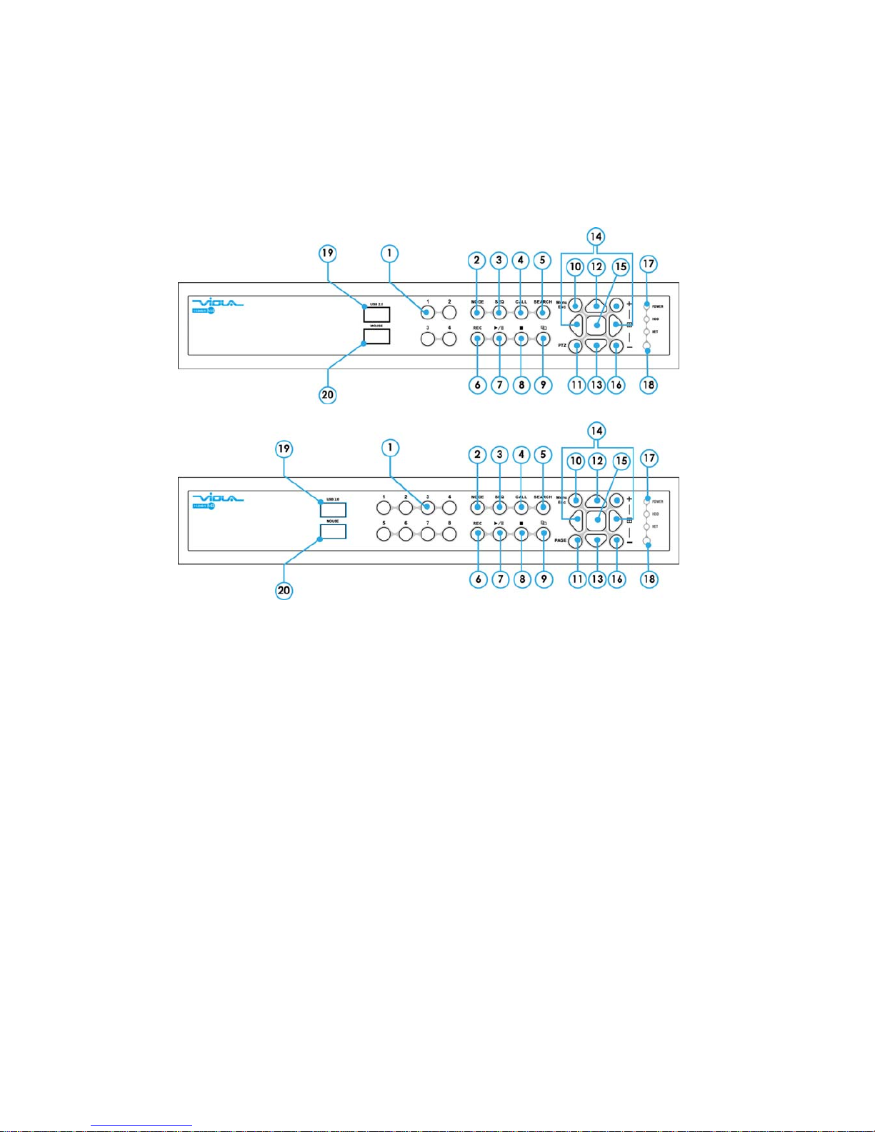
2.1 Front Panel
1. Alpha-numeric Buttons (1-4/8)
Press these buttons for camera selection in most of the circumstances.
These buttons can also be used to enter text and number in the way
similar to most of the mobile phones.
2. MODE Button
Press this button to toggle between live mode and playback mode in main
screen display. In some dialogs, this button is used as a miscellaneous
function key. At playing, this button is used as “slow backward”.
3. SEQ Button
Press this button to switch to or return from SEQ display mode in main
screen display. In some dialogs, this button is used as a miscellaneous
function key. At playing, this button is used as “slow forward”.
4. CALL Button
Press this button to switch to or return from full screen display of the focus
camera in main screen display. In some dialogs, this button is used as a
miscellaneous function key.
Page 10

- 10 -
5. SEARCH Button
Press this button to display the search menu in main screen display. In
some dialogs, this button is used as a miscellaneous function key.
6. REC Button
Press this button to force manual recording. To stop manual recording,
press it again.
7. Play/Pause Button (
)
Press this button to play the recorded images, or pause the playback.
8. Stop (
) Button
Press this button to stop the playback.
9. Copy(
) Button
Press this button to copy the playback images to the storage device
connected to the USB port. Press this button again to stop copying.
10. MENU / ESC Button
Press this button to display the main menu or escape to the upper level
display.
11. PAGE Button (8-CH) / PTZ Button (4-CH)
8-CH: Press this button for page down in multi-split-window displays.
4-CH: In main screen display, press this button to enter/exit PTZ control if
the focus camera is a PTZ camera.
12. Up/BS Button (▲/BS)
Press this button to move the cursor or focus window in most
circumstances. In PTZ control, press this button to tilt up the camera. In
text editing mode, this button is used as “backspace” key.
13. Down/DEL Button (▼/DEL)
Press this button to move the cursor or focus window in most
circumstances. In PTZ control, press this button to tilt down the camera.
In text editing mode, this button is used as “del” key. In playback mode,
press this button for single step.
14. Left/Right Buttons (◄,►)
In PTZ control, press these buttons to pan the camera. In playback mode,
press these buttons for fast backward/forward. In the other screens,
press these buttons to move the cursor or focus window.
15. ENTER Button
This button is used as “enter” key in most circumstances. In PTZ control,
this button is used to start/stop the selected PTZ control mode.
Page 11

- 11 -
16. (Split Windows) +/- Buttons (
)
In split-window display, press these buttons for next/previous split-window
display. In the others, press these buttons to change the contents.
17. LEDs
Indicators for POWER, HDD and Network access.
18. Remote I/R Sensor
Used to receive signal from I/R remote controller.
19. USB2.0 Connector
Connect to USB 2.0 compatible storage device, such as USB 2.0 disk
drive, DVD+RW, card reader, etc.
20. USB Mouse Connector
Connect to USB1.1 mouse before the DVR is power on.
Page 12
- 12 -
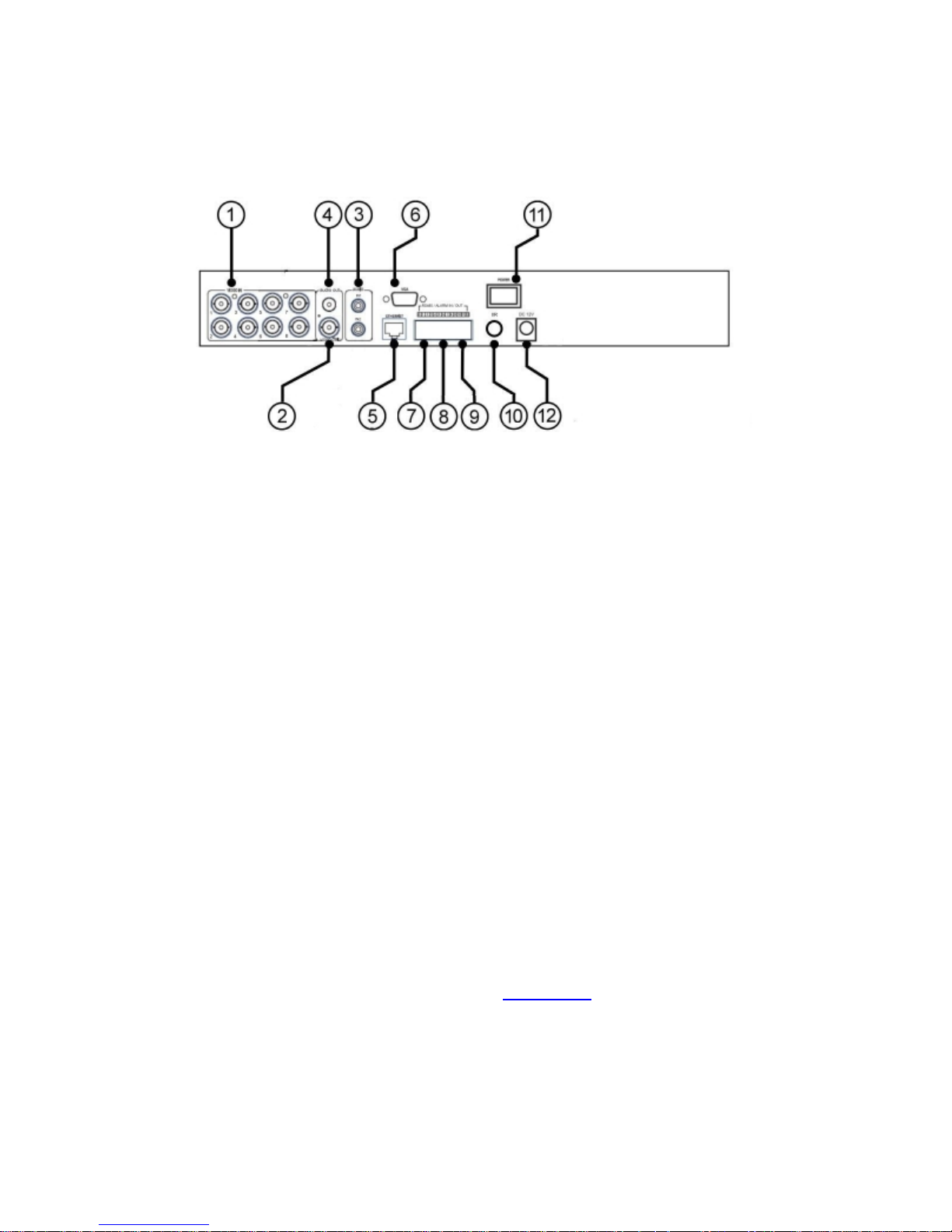
2.2 Back Panel
1. Video Input Connectors (1-4/8)
Connect system cameras to these BNC connectors. The internal 75Ω
termination is always ON.
2. Main Monitor Output Connectors (MAIN OUT)
Connect TV monitors to the BNC connector for main monitor display.
3. Audio Input Connectors (AUDIO IN)
The RCA connector accepts line-in audio signal supplied from external
devices such as microphone amplifiers.
4. Audio Output Connectors (AUDIO OUT)
The connector supplies line-out audio signal to external devices such as
speakers. Recorded audio will be supplied from AUDIO OUT during
playback.
5. Ethernet Connector
Connect this unit to a 10/100Base-T Ethernet network through this port.
6. Main Monitor Output VGA Connector (VGA)
Connect VGA monitor to the optional D-SUB 15-pin female connector for
main monitor display. Please note there won’t be video signal for
MAIN OUT BNC connector if VGA is connected.
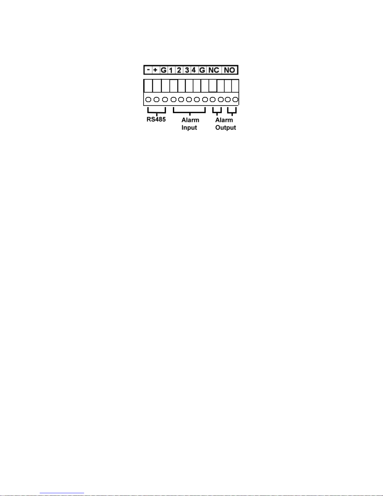
7. RS-485 Connector
Connect this connector to RS-485 compatible PTZ camera(s) or keyboard.
Please refer to the manuals come with the RS-485 compatible devices for
the correct settings. Please refer to Appendix D
for the Keyboard Control
Protocol for the digital video recorder.
Page 13
- 13 -
8. Alarm Input Connectors (ALARM IN 1-4)
Connect these connectors to external devices such as sensors or door
switches.
9. Alarm Output Connectors (ALARM OUT NC(1)/NO(2))
Connect NC connectors (left) to Normally Closed (NC) alarm output, or
NO connectors (right) to Normally Open (NO) alarm output. Please note
that only one of the NC or NO connectors can be connected only.
10. I/R Extension Connector (I/R, optional)
Optional I/R extension connector to receive signal from I/R remote
controller.
11. Power Switch (POWER)
Turn the power of this unit on/off.
12. Power Cord Inlet (DC 12V)
Connect to DC +12V power source.
Page 14

- 14 -
2.3 Remote Controller
The remote controller is an optional accessory to ease the user’s operations. You can
do all the operations by the remote controller instead of the buttons on the front panel.
The effective distance is about 10 meters without any obstacle.
Most of the buttons corresponds to one of those buttons on the front panel. Please
refer to the descriptions in Section 2.1.
For the other buttons, the descriptions are as
below:
1. Alpha-numeric Buttons (1-9, 0, *, #)
Press these buttons for camera selection in most of the circumstances.
These buttons can also be used to enter text and number in the way
similar to most of the mobile phones. ‘*’ is also used to reset channel
numbers in split-window display.
2. Alarm Reset Button
Press this button to cancel alarm activation, and return the system to the
condition before the alarm was activated.
3. MUTE/NEXT Button
In PTZ control, press this button for the next miscellaneous control. In
the other screens, press this button to mute the audio.
4. X2/GOTO Button
In PTZ control, press this button to move the camera to the preset position.
In full screen display, press this button for Digital Zoom (X2/X4).
5. (Vol/Zoom) +/- Buttons (
/ / )
In PTZ control, press these buttons to zoom in/out the camera.
Page 15
- 15 -
3. Installations
The installations described below should be made by qualified service personnel or
system installers.
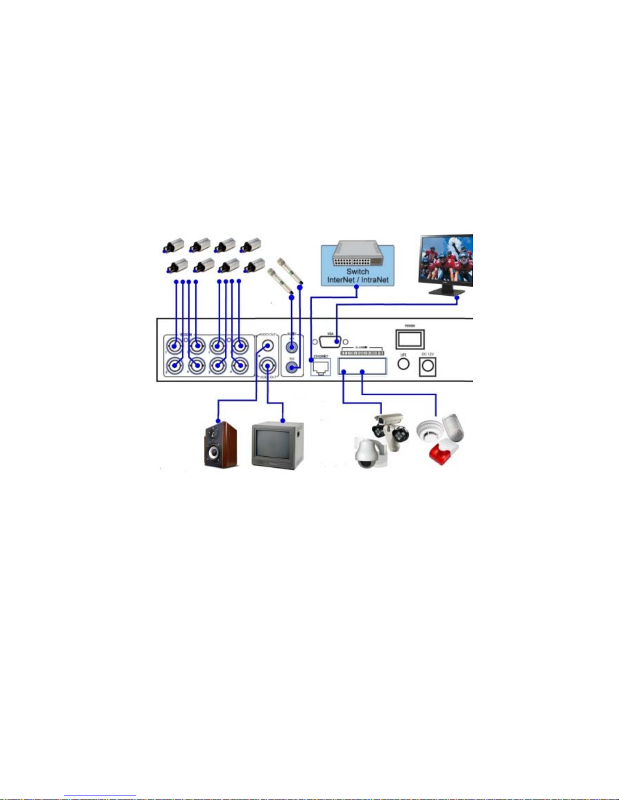
3.1 Basic Connections
Please refer to the following diagram for the connections.
Please make sure to set the NTSC/PAL Selector Switch on the main board
according to the local TV system for the system to work correctly.
Cameras
Connect the camera video input connectors to the video outputs from system
cameras or other composite video sources via coaxial cables. The internal 75Ω
termination is always ON.
Main monitor
Connect the main monitor output connector (BNC) to a surveillance TV monitor,
or connect the VGA output connector to a VGA monitor. The TV/VGA
monitor displays selected live or recorded cameras in any available split window
format. Please note there won’t be video signal for MAIN OUT BNC
connector if VGA is connected.
Power
Page 16
- 16 -
Connect DC 12V power source to DC 12V.
3.2 Optional Connections
Audio input
Connect the audio input connector to the audio line-out from system cameras or
other audio sources. Please make sure to associate the audio inputs with the
cameras in Camera Setup as described in Section 6.2
accordingly.
Audio output
Connect the audio output connector to the audio line-in from speakers.
Alarm inputs
Connect the alarm inputs to NC and/or NO type of alarm signals. Please make
sure to setup the alarm configurations as described in Section 6.3
accordingly.
Alarm outputs
Connect the alarm output #1 to NC type of alarm signal, or alarm output #2 to NO
type of alarm signal.
Ethernet
Connect the Ethernet connector to a standard twisted-pair Ethernet cable for
remote access via LAN or internet. Please make sure to setup the related
configurations as described in Section 6.10 Network Setup
.
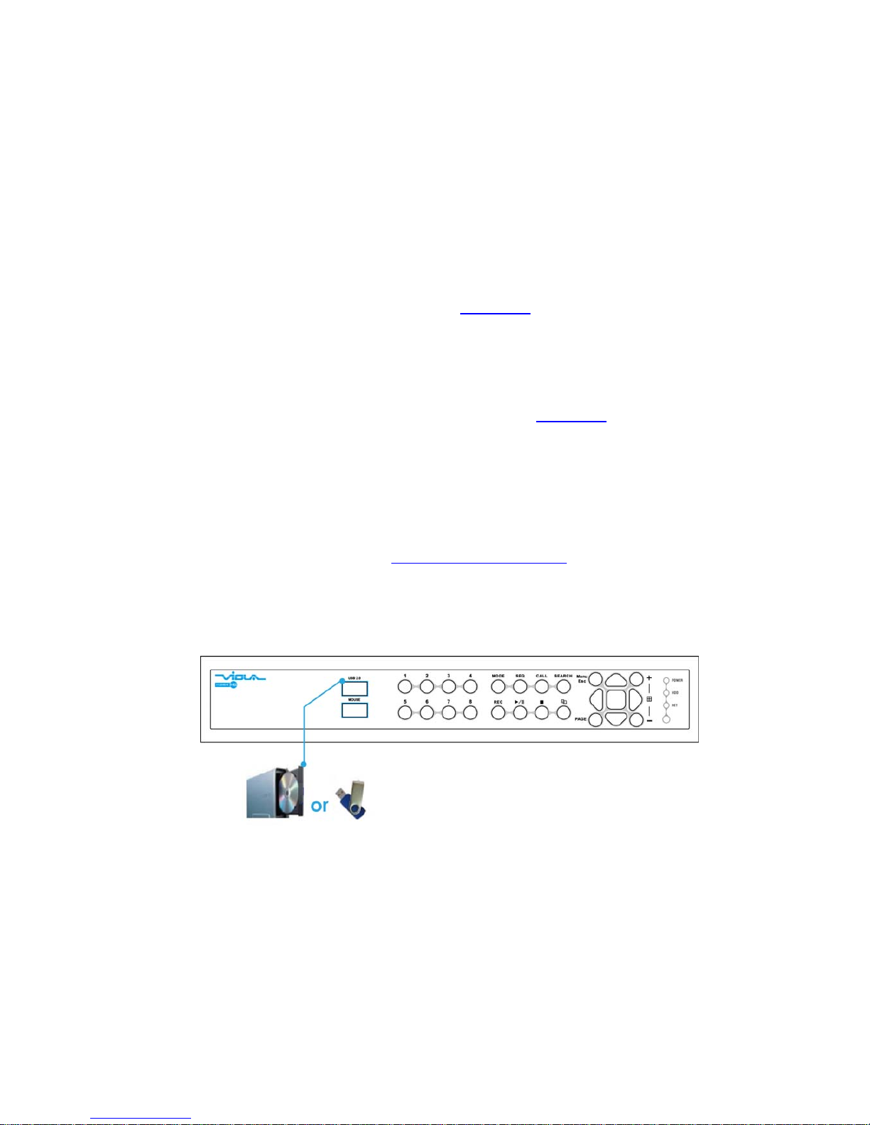
USB 2.0 disk drives, DVD+RW, card reader, etc.
If the user wants to use USB2.0 peripheral device to retrieve important recorded
images and/or audio, please connect it to the USB2.0 port connector.
Page 17

- 17 -
I/R remote controller
The user may use I/R remote controller to control the digital video/audio recorder.
PTZ Cameras
Connect the RS-485 connector to PTZ camera(s) via the appropriate cable. The
system supports a variety of different PTZ cameras, including Pelco D protocol
Dome, SamSung SCC-641P, Kalatel Cyber Dome, Bosch AutoDome, etc. But
different PTZ cameras can coexist in a system only if they support the same
protocol. Please make sure to set the PTZ ID of the camera(s), and setup the
camera (Section 6.1
), and RS-232 or RS-422/485 (Section 6.9) accordingly.
RS-485 keyboard or Terminal
Connect the RS-485 connector to a RS-485 keyboard controller or VT-100
terminal via the appropriate cables. Please refer to the diagram above for the
correct connection. Please make sure to setup the RS-422/485 configurations as
described in Section 6.9
accordingly. Please refer to Appendix D for the
Keyboard Control Protocol for the digital video recorder.
Page 18
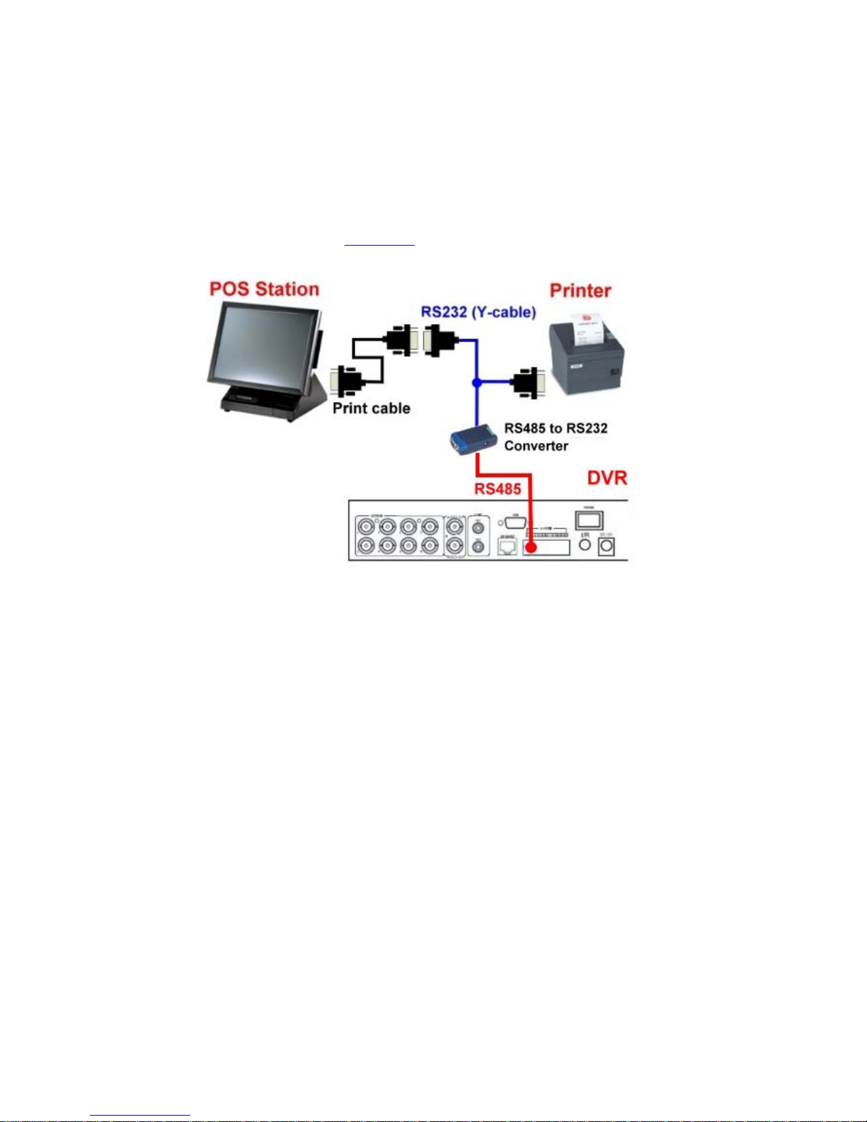
- 18 -
POS system
Connect the RS-485 connector to POS system via the appropriate cable. The
system supports the POS systems which can be connected to the following
printers – Epson-TM200, Epson-TMU295, Epson-TMU300, Epson-TMU675,
Epson-TMT882, Epson-RPU420, and Epson-MD332S. Please make sure to
setup the RS-485 port (Section 6.9
) accordingly.
Page 19
- 19 -
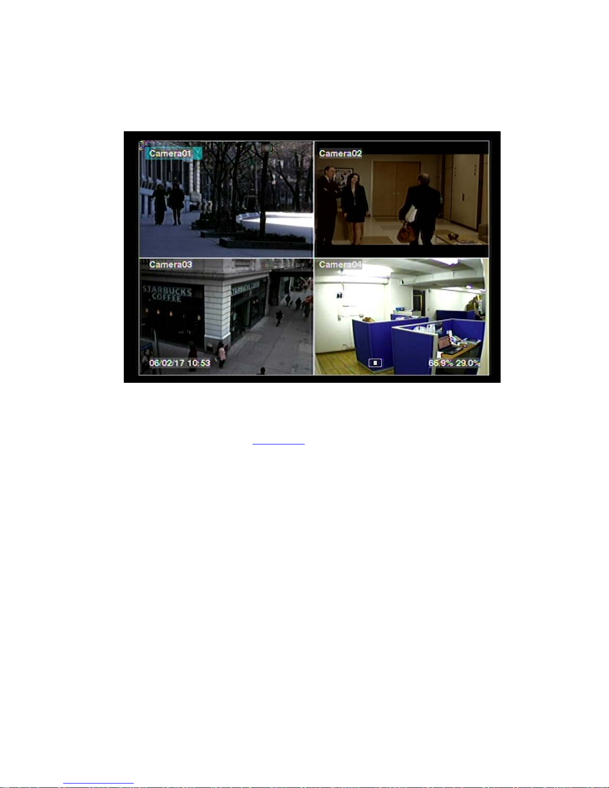
4. Main Screen And Basic Operations
The split-window screen, as shown above, is the main screen after system startup.
There are two types of split-window screens, including 1-Window, 4-Window,
7-Window, and 9-Window. The system will remember the last one before normal
shutdown (as described in Section 5.7
) of the system. In addition to the split
windows, the system time is displayed on the lower-left corner, the system states on
the lower-right corner, and the rolling screen messages, if shown while certain event
occurs, on the lower corner.
The system states, from right to left, are described as the followings:
(1) Normal recording percentage,
(2) Alarm recording percentage,
(3) Mute state – speaker icon shown for not mute, not shown for mute,
(4) X2 state – X1, X2, or X4,
(5) Manual record ON/OFF – REC icon shown for ON,
(6) Backup state – Backup icon shown for backup, and
(7) SEQ display ON/OFF or playback state – SEQ icon shown for SEQ display ON,
other icons for different playback states.
* If mouse is connected, the mouse operation icons will be shown when the mouse
cursor is moved to the bottom of the screen.
* Recording icon, Motion, & Alarm for the camera may be shown after camera title.
Page 20

- 20 -
4.1 Text Input
There are certain circumstances that the system requires the user to enter text, such as
system login, camera title setup, and so on. Please follow the steps below to enter
text:
(1) Press ENTER to edit the highlighted option. The flashing cursor will be shown
to indicate the editing point.
(2) Press ◄► to move the cursor to the left/right.
(3) Press code in text editing mode to change text case. (If this entry can accept
number only, pressing code will have no effects.) Indicators on the screen show
the current setting:
123 = Number only
abc = No capital letters
ABC = All capital letters
CODE = Internal code for the selected language, such as Chinese, Japanese, etc.
(4) Press a number key (1-9, 0) repeatedly until the character you want appears (1 for
1 or space, 2 for 2, a/A, b/B, or c/C, etc.). If internal CODE is selected, a
CODE box will be shown (after the first code is entered) for each new code to be
entered. Please check the internal code table for the selected language. For
2-byte code, e.g. Chinese or Japanese, the code accepted is from 0000 - FFFF.
(5) Press mark to bring up a list of punctuation marks and special characters. The
highlighted character in the list shows the selected one. Press ▲▼◄► to
change the selection.
(6) If you make a mistake, press BS to remove the character to the left of the cursor,
or press DEL to delete the character at the current cursor position.
(7) In text editing mode, internal code box, and mark list, press ENTER to exit and
save changes, press ESC to exit without making changes.
Note: If the user clicks on the left button of the mouse on the item, a Keyboard
Simulator will be shown. Click on ‘#’ (or “abc”, ..) to change text case.
Click on the alpha-numeric characters to enter text (or CODE). Click on ‘*’
for mark.
Page 21
- 21 -
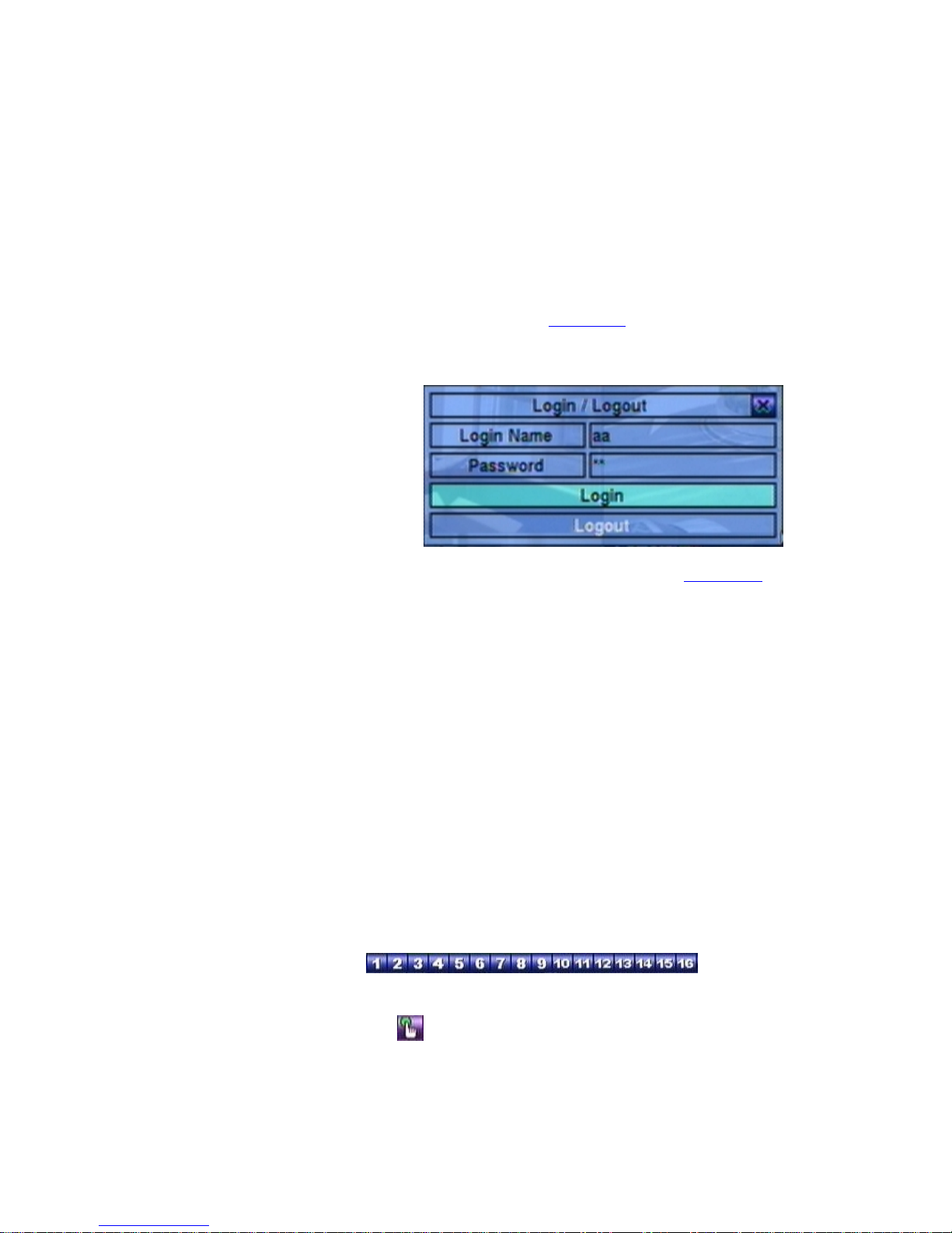
4.2 Login And Logout
There are three password levels in the system, including Administrator (highest),
Supervisor, and Operator (lowest). If the user does not login the system, he/she
will be treated as “Guest” and can only view live video display.
The system allows up to 18 user accounts. The administrator can set up the login
name and password for each user. (Please refer to Section 6.7
for Password Setup.)
The Operator can operate live video display, the Supervisor live video display, image
playback and archive, and the Administrator everything.
To login/logout the system,
press MENU in split-window
display to call up Menu display,
and then press ENTER when
the highlighted option is
Login/Logout to enter
Login/Logout display as
shown.
In Login/Logout display, follow the Text Input method described in Section 4.1
to
enter the Login name and Password, press ▲▼ to highlight and select Login option,
and then press ENTER to login the system. If the user wants to logout the system,
just press ▲▼ to highlight and select Logout option, and then press ENTER. Press
ESC (Mouse: Right Click) to exit without making changes.
There is one factory-preset login name/password aa/11 at Administrator level. The
user can use it to login the system for the first time.
Should the user have forgotten all the administrator-level passwords, please
contact the local dealer or installer to recover from it.
4.3 Basic Operations
The basic user’s operations after he/she has logged into the system are described
below:
Numeric (Mouse:
)
Press these buttons to switch to the full-window display for the camera.
Alarm Reset (Mouse:
)
Press this button to cancel alarm activation, i.e. reset the alarm outputs and silence
Page 22

- 22 -
the buzzer.
MODE (Mouse:
) (Administrator/Supervisor)
In split-window display, press this button to change circularly the live/playback
mode for the focus window and the other windows that form a rectangle on the
screen.
SEQ (Mouse:
)
Press this button to switch to or return from SEQ display mode. In SEQ display
mode, each page in the sequence will be shown for the preset page dwelling time
sequentially, and SEQ icon will be shown on the lower-right corner of the screen.
CALL (Mouse: left-click in focus camera window)
In split-window display, press this button to switch to or return from full screen
display of the focus camera.
SEARCH (Mouse:
) (Administrator/Supervisor)
In split-window display, press this button to display the search menus. The
system will remember the last one the user chose.
REC (Mouse:
)
Press this button to force manual recording. To stop manual recording, press it
again. All cameras will be recorded as if the scheduled record is A/V, and REC
will be shown on the lower-right corner of the screen if manual recording is ON.
MENU (Mouse:
) / ESC (Mouse: Right Click)
In split-window display, press this button to display the versatile menu.
PTZ (Mouse:
)
In split-window display, press this button to enter PTZ control mode if the focus
camera is a PTZ camera.
X2 (Mouse:
)
In full screen display, press this button to enter Digital Zoom mode. Please refer
to Section 4.4 Digital Zoom
for the detailed operations in Digital Zoom mode.
▲▼◄► (Mouse: left-click)
Press these buttons to move focus. The title of the camera for the focus window
is highlighted as shown on the screen.
Vol+/- (
/ ), MUTE (Mouse: )
Press these buttons to control the volume.
Page 23

- 23 -
+/- (Mouse: )
Press these buttons to circulate up/down among the available split-window
displays.
PAGE (I/R remote controller: #, Mouse: current split-window icon)
Press this button for page down in multi-split-window displays.
ENTER (Mouse:
)
Press this button to display the GPS/POS data if there’s GPS/POS data fed to the
DVR. Please select the Type (GPS or POS), Position, Background, Rows, and
number of Characters on the screen, and then press ENTER to display the
GPS/POS data, or ESC to cancel. The user may also enable/disable OSD
display for certain fields in main screen. In GPS/POS display, press ▲▼ for
page up/down, press ENTER to close it, or press MENU/SEARCH/.. to call up
the corresponding display as if there’s no GPS/POS display.
4.4 Digital Zoom
The system supports X2/X4 Digital Zoom function. To use this function, press X2
button (Mouse:
) in full screen display to enter Digital Zoom mode. There will
be a zoom window shown in the video window as shown. The zoom window (a)
will always be shown at zoom factor X1, (b) can be shown or hidden at zoom factor
X2, and (c) will never be shown at zoom factor X4. The operations in Digital Zoom
Page 24

- 24 -
mode are as below:
▲▼◄► (Mouse: Click in the video window)
Press these buttons to
(a) move the zoom window if it’s shown in the video window, or
(b) navigate the video window around if the zoom factor is X2 or X4.
ENTER (Mouse: Click in the video window)
Press this button to zoom in the zoom window, from X1 to X2 or from X2 to X4,
if the zoom window is shown in the video window.
X2 (Mouse:
)
Press this button to
(a) show/hide the zoom window if the current zoom factor is X1/X2, or
(b) zoom out the video window back to zoom factor X1 if the current zoom factor
is X4.
ESC (Mouse:
or Right Click)
Press this button to escape from Digital Zoom mode, and return to normal full
screen display. The video window will always return to zoom factor X1.
Page 25
- 25 -
5. Menu Display
In split-window display, press MENU (Mouse: ) to call up Menu display as
shown.
There are a variety of displays under Menu display. In Menu display and all the
subsequent displays, the items enabled are shown in black-colored text, and those
disabled in white-colored text. Please refer to Appendix B
for the Structure Of
Menu Displays. Please refer to Section 4.2
for Login/Logout display.
The user’s operations are described as the followings:
▲▼◄►
Press these buttons to change the highlighted item.
ENTER (Mouse: Click in the menu item)
Press this button to enter the detailed display of the highlighted option. For the
details of each option, please refer to the following sections.
ESC (Mouse: Right Click)
Press this button to escape from Menu display, and return to split-window display.
Page 26
- 26 -
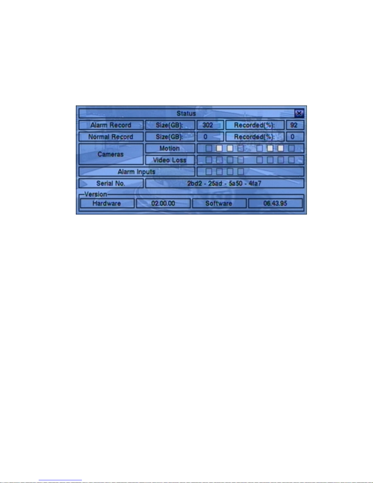
5.1 Status Display
In Menu display, press ▲▼◄► to change the highlighted option to Status, and then
press ENTER to call up Status display as shown.
Status display includes Alarm Recording Status, Normal Recording Status, Camera
Status, Alarm Input Status, Product Serial Number, and Product Version Number.
Press ESC (Mouse: Right Click) to escape from Status display, and return to Menu
display.
Page 27

- 27 -
5.2 Volume Control
In Menu display, press
▲▼◄► to change the
highlighted option to Vo lu me ,
and then press ENTER to call
up Volume Control display as
shown.
The general operations are as
below:
▲▼◄► (Mouse: Click in the respective item)
Press these buttons to select the items.
ESC (Mouse: Right Click)
Press this button to escape from this screen, and return to Menu display. If the
contents have been modified, a Save dialog will be shown to ask the user to save
the changes, press ENTER to exit and save, ESC to exit without saving.
Following is a brief description for each item and its specific operations:
Mute – to mute the selected audio channel. Press ENTER or +/- to
check/uncheck this item. The default setting is “-” - unchecked.
Vo lu me – the volume of the selected audio channel. Press +/- buttons to change
the value (1-10).
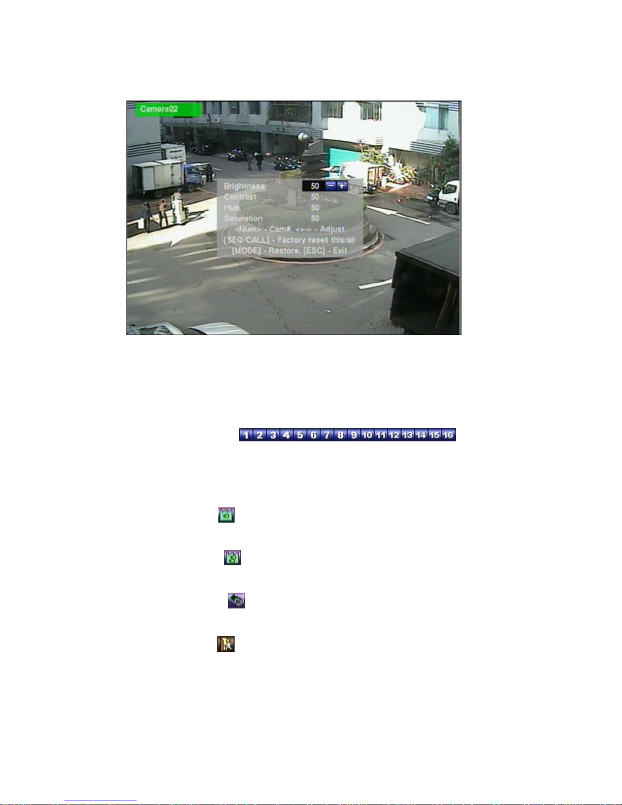
5.3 Video Adjustment
In Menu display, press ▲▼◄► to change the highlighted option to Video
Adjustment, and then press ENTER to call up Video Adjustment display as shown.
Page 28
- 28 -
There are 4 items which can be adjusted, including Brightness, Contrast, Hue, and
Saturation. The operations are as below:
▲▼
Press these buttons to select the items.
Numeric (Mouse:
)
Press these buttons to change the camera.
+/-
Press these buttons to adjust the selected item.
SEQ (Mouse:
)
Press this button to reset the settings for this camera to factory default values.
CALL (Mouse:
)
Press this button to reset the settings for all cameras to factory default values.
MODE (Mouse:
)
Press this button to restore the values.
ESC (Mouse:
or Right Click)
Press this button to escape from this screen, and return to Menu display. The
settings will be saved for future reference.
Page 29
- 29 -
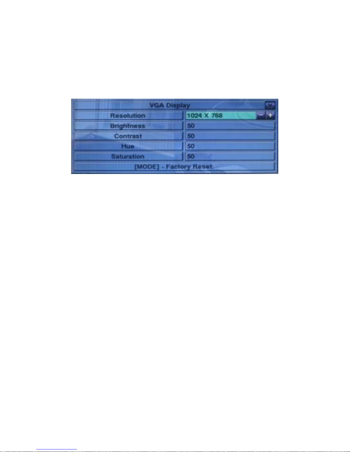
5.4 VGA Display
In Menu display, press ▲▼◄► to change the highlighted option to VGA Display,
and then press ENTER to call up VGA Display dialog as shown.
There are 5 items which can be adjusted, including Resolution (only 1024x768 for
this model), Brightness, Contrast, Hue, and Saturation. The operations are as below:
▲▼ (Mouse: Click in the respective item)
Press these buttons to select the items.
+/-
Press these buttons to adjust the selected item.
MODE (Mouse: Left click)
Press this button to restore Brightness, Contrast, Hue, and Saturation to factory
default values.
ESC (Mouse: Right Click)
Press this button to escape from this screen, and return to Menu display. If the
contents have been modified, a Save dialog will be shown to ask the user to save
the changes, press ENTER to exit and save, ESC (Mouse: Right Click) to exit
without saving.
Page 30
- 30 -
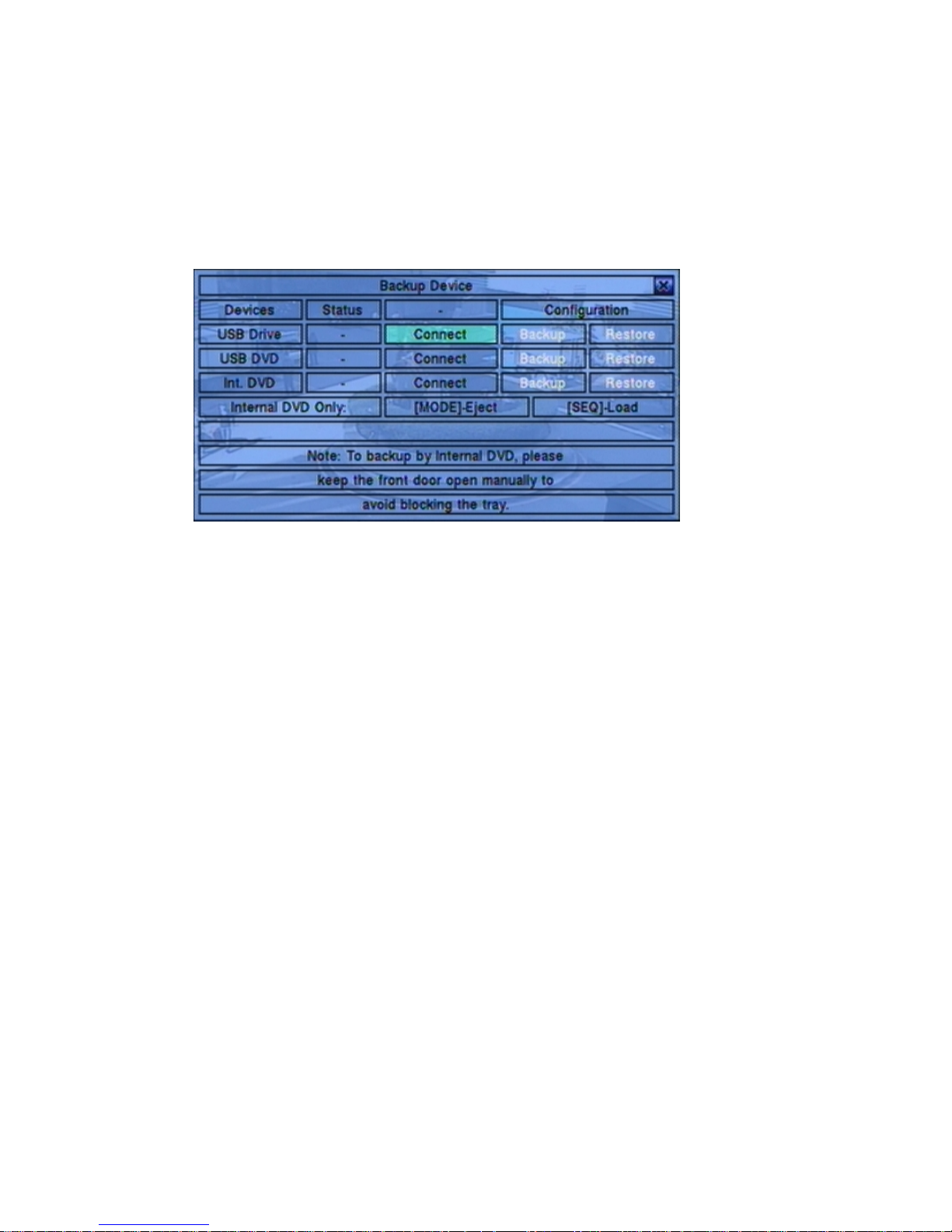
5.5 Backup Device
In Menu display, press ▲▼◄► to change the highlighted option to Backup Device,
and then press ENTER to call up Backup Device display as shown below.
The system supports a variety of USB 2.0 storage devices, including Storage Disk
Drives and DVD Disc (including DVD+RW, DVD+R, and DVD-R). (DVD-RW is
not supported.) The operations are as below:
▲▼◄►
Press these buttons to select the items.
ESC (Mouse: Right Click)
Press this button to escape from this screen, and return to previous display.
Connect/Disconnect – If the backup device is disconnected (as shown in Current
Status), please plug the device in the USB port and/or insert a DVD for DVD
device, and then press ENTER (Mouse: Left click) to command the system to
connect with it. If the device is already connected (EX. R/W - Read/write, as
shown in Current Status), please press ENTER (Mouse: Left click) to
command the system software to disconnect with the device, and then unplug the
device from the backup port.
Note 1: DO NOT format the DVD disc for better performance and compatibility.
Note 2: Before using USB pen drive, please format it to FAT32 file system by
MS-Windows.
Note 3: The backup device has to be connected by the system software before it
can be used to read/write. If it failed to connect, please unplug the
device, and then plug the device in the USB port again.
Page 31

- 31 -
Note 4: Some backup devices may have compatibility problems. Please contact
your local dealer or installer for the supported devices.
Backup
Press ENTER (Mouse: Left click) when this item is selected to backup the
configurations of this unit to the corresponding USB device. The user may
enter the directory to backup the configurations to.
Restore
Press ENTER (Mouse: Left click) when this item is selected to restore the
configuration files in the corresponding backup device to this unit. The user
may enter the directory to restore the configurations from.
Some USB 2.0 Devices Tested
USB-Storage Enclosures 5.25” –
Macpower’s Alumni Prefect USB 2.0 - PF-U2MS
USB-Disk Storage –
Transcend’s JetFlash 150/V60 Series, JetFlash V33 8GB
Apacer’s Handy Steno AH220
Pretec’s i-Disk Wave 512M-Black
Kingston’s DataTraveler USB Flash Driver(DTI/512FE)
Kingston’s DataTraveler DT100 8GB
SanDisk’s Cruzer micro USB Flash Driver
Sandisk’s Cruzer Titanium 4GB, Cruzer Contour 4GB
Sony’s MICRO VAULT Classic Series
OCZ’s ATV 4GB, Rally2 4GB
DVD Writer –
Asus DRW-1608P Series
Pioneer DVR-A11, DVR-X152 Series
BenQ EW200G Series
LITEON LightScribe DVD Writer SHM-165H6S, 20X DVD Writer DX-20A4P
Sony DVD/CD Rewritable Drive Model DRX-810UL Series
NEC DVD/CD Rewritable Drive Model ND-4550A Series
HP dvd9404e External 18X Super Multi DVD Writer Series
Some DVD Discs Tested – Only single-side, single-layer disc supported
Infomedia DVD+R 16X
Mitsubishi DVD+RW 1-4X
Page 32

- 32 -
Philips DVD+RW 1-4X
Ritek DVD-R 8X, DVD+RW 1-4X
Verbatim DVD+RW 1-4X
Page 33

- 33 -
5.6 Software Upgrade (Administrator)
In Menu display, press ▲▼◄► to change the highlighted option to Software
Upgrade, and then press ENTER to call up Software Upgrade display as shown.
The operations are as below:
▲▼◄► (Mouse: Left click)
Press these buttons to select the items.
ESC (Mouse: Right Click)
Press this button to escape from this screen, and return to Menu display.
Following is a brief description for each item and its specific operations:
Backup Device – press ENTER (Mouse: Left click) to call up Backup Device
dialog (if there’s no backup device connected).
Disk Storage – to select the disk storage to upgrade. Press +/- buttons to select
the available storage.
Upgrade File – press ENTER (Mouse: Left click) to start the upgrade process
when the highlighted file is a correct upgrade file. A confirmation dialog will be
shown on the screen, press ENTER to confirm to upgrade the system software.
Note : After the software is upgraded, the system will restart immediately. The
split window display will be shown after restart, please wait a moment.
Page 34

- 34 -
5.7 System Shutdown (Administrator)
In Menu display, press ▲▼◄► to change the highlighted option to Shutdown, and
then press ENTER (Mouse: Left click) to shutdown the system. A confirmation
dialog will be shown on the screen, press ENTER to confirm the shutdown. The
system will save all the files and all the states, and then display a power-off message
in the rolling screen message area. The user may power off the system safely when
the power-off message is shown.
Page 35

- 35 -
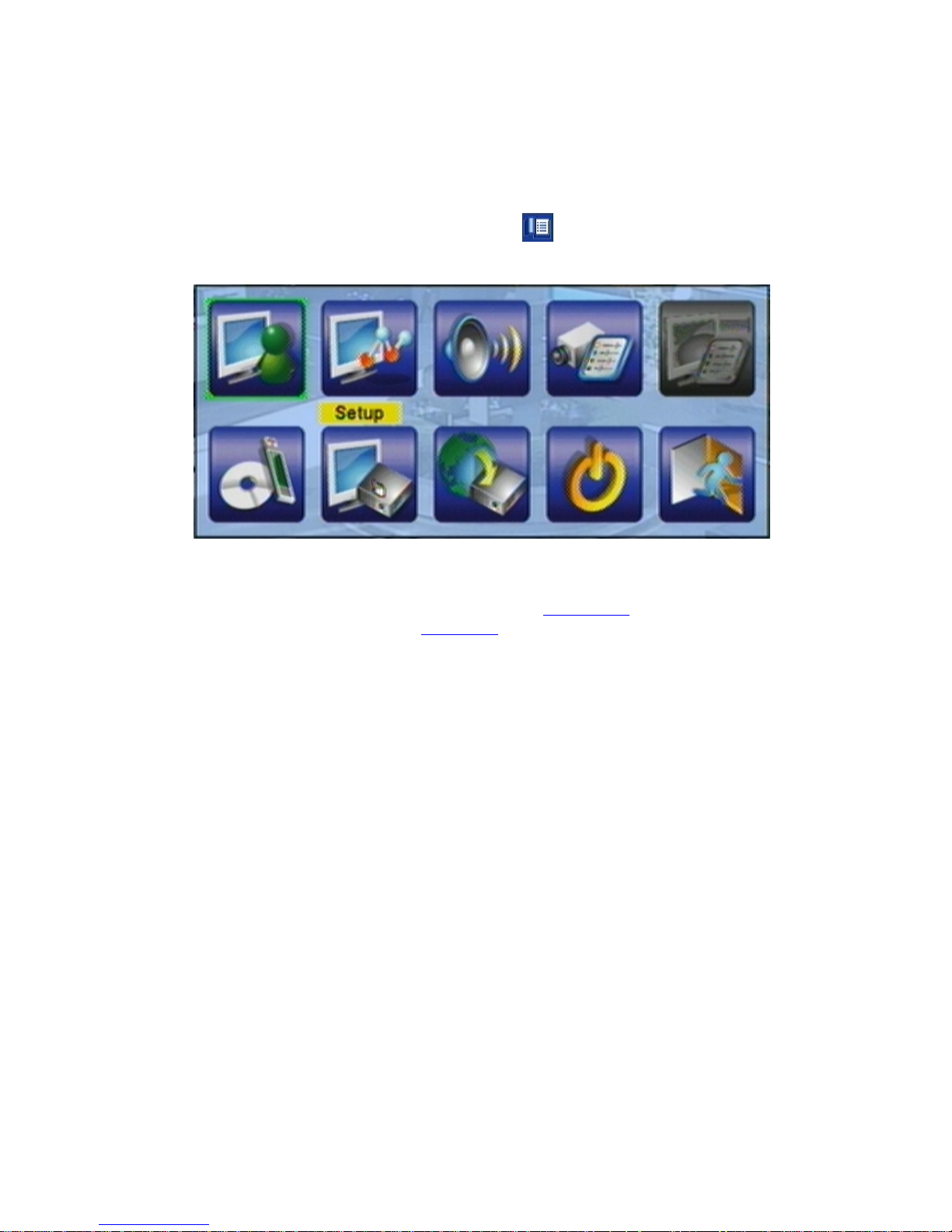
6. Setup (Administrator)
In Menu display, press ▲▼◄► to change the highlighted option to Setup, and then
press ENTER to call up Setup Menu display as shown. (To enter Setup Menu
display of the system, please login as Administrator first.)
The user’s operations are described as the followings:
▲▼◄►
Press these buttons to change the highlighted item.
ENTER (Mouse: Left click)
Press this button to enter the setup of the highlighted option. For the details of
each option, please refer to the following sections.
ESC (Mouse: Right Click)
Press this button to escape from Setup Menu display, and return to Menu display.
If the user wants to reset all the settings to factory default values, he/she may press
▲▼◄► to change the highlighted option to Factory Defaults, and then press
ENTER. A confirmation dialog will be shown, press ENTER again to make the
changes, ESC (Mouse: Right Click) to not do it.
Page 36

- 36 -
6.1 Pre-Camera Setup
In Setup Menu display, press ▲▼◄► to change the highlighted option to
Pre-Camera, and then press ENTER (Mouse: Left click) to call up Pre-Camera
Setup display.
There are up to 8/4 cameras which can be connected to the system. The Pre-Camera
Setup allows the administrator to define some fundamental attributes for all the
installed cameras.
The general operations are as below:
▲▼◄►
Press these buttons to select the items.
Numeric
Press these buttons to select the camera.
ESC (Mouse: Right Click)
Press this button to escape from this screen, and return to Setup Menu display. If
the contents have been modified, a Save dialog will be shown to ask the user to
save the changes, press ENTER to exit and save, ESC (Mouse: Right Click) to
exit without saving.
Following is a brief description for each item and its specific operations:
REC Resolution – the record resolution for all the cameras in the system. For
NTSC, it can be 720x480, 720x240, or 360x240; for PAL, 720x576, 720x288, or
360x288. Press +/- buttons to select the resolution.
Page 37

- 37 -
Watermark – to record with digital watermark or not. If yes, all the recorded
images for all the cameras will have digital watermark embedded. Press
ENTER or +/- (Mouse: Left click) to check/uncheck this item. The default
setting is “ˇ” - checked.
Installed – whether this camera is installed or not. If installed, the following
items will be settable. Press ENTER or +/- (Mouse: Left click) to
check/uncheck this item. The default setting is “ˇ” - checked.
PTZ ID – the PTZ ID of this camera if it’s a PTZ camera. The PTZ ID has to be
consistent with the setting of this camera. Please refer to the manual of the
camera for the ID setting. Press +/- buttons to change the value (N/A or 0-255).
The default setting is “N/A” – Not Available, which means that it’s not a PTZ
camera.
6.2 Camera Setup
In Setup Menu display, press ▲▼◄► to change the highlighted option to Camera,
and then press ENTER (Mouse: Left click) to call up Camera Setup display.
The Camera Setup allows the administrator to define the attributes for each camera.
There are up to 8/4 cameras which can be connected to the system.
The general operations are as below:
Page 38

- 38 -
▲▼◄► (Mouse: Left click)
Press these buttons to select the items. The display will scroll left/right if the
selected item is not shown on the screen.
Numeric
Press these buttons to select the camera.
COPY (
)
Press this button to copy all the settings - excluding detailed Motion settings,
Video Loss settings, Title/Audio - of the focus camera to all the following
cameras. (EX. focus camera is 1, its settings will be copied to those of cameras
2-8/4.)
ESC (Mouse: Right Click)
Press this button to escape from this screen, and return to Setup Menu display. If
the Save dialog is shown, press ENTER to exit and save, ESC (Mouse: Right
Click) to exit without saving.
Following is a brief description for each item and its specific operations:
Title – The title (Max. 8 characters) of this camera. Please follow the Text Input
method described in Section 4.1
to modify this item.
Video Loss Settings.. – used to setup the action settings when video loss is
detected for this camera. Press ENTER (Mouse: Left click) in Settings.. to
call up Video Loss Setup display for the camera. Please refer to Section 6.2.1
for the details.
Motion Detection – whether the motion detection of this camera is enabled or not.
(Note : this field has no effect for the Smart Search information.) Press
ENTER or +/- to check/uncheck this item. The default setting is “ˇ” - checked.
Motion Settings.. – used to setup the motion settings, used for Motion Detection
or Smart Search, for this camera. Press ENTER (Mouse: Left click) in
Settings.. to call up Motion Setup display for the camera. Please refer to Section
6.2.2 for the details. Please note that if the Motion Detection is disabled, the
default factory motion settings should work fine for Smart Search.
Covert – covert or not. If the camera is covert, the video of this camera can only
be seen if the user has logged in as Administrator. Press ENTER or +/- (Mouse:
Left click) to check/uncheck this item. The default setting is “–” - unchecked.
Call By Event – whether to switch the monitor to the video of this camera if
certain event occurs for this camera. There are 4 options, including Off, Motion,
Alarm, Both (Motion & Alarm). Press +/- buttons to select one.
Page 39

- 39 -
Dwell Time – the dwell time if Call By Event is set to Motion, Alarm, or Both.
Press +/- buttons to adjust the value (3-60 seconds, discrete).
Audio – the AUDIO IN corresponding to this camera. The audio data for the
selected AUDIO IN will be recorded with the video data for this camera. Press
+/- buttons to select none (N/A) or AUDIO Inputs (1, 2). The default setting is
“N/A”.
Record Quality – the record quality for this camera. Press +/- buttons to select
the value (1-9, with 1 the lowest (rough) quality, 9 the highest (fine) quality).
Event Record IPS – the IPS (Images Per Second) for this camera if certain event
(Motion, Alarm) occurs for this camera. This camera will be recorded at this
rate for Post-record time since the event occurs. (Please refer to the following
sections for Post-record time.) Press +/- buttons to select the value (0 – 25 (PAL)
/ 30 (NTSC), discrete).
Pre-record IPS – the pre-record IPS for this camera if certain event (Video Loss,
Motion, Alarm) occurs for this camera. This camera is recorded at this rate for
Pre-record time before the event occurs. (Please refer to the following sections
for Pre-record time.) For this DVR, the value is always the same as Event
Record IPS. Please note that the total Event Record IPS / Pre-record IPS
should not exceed the system recording capacity (NTSC: 240/CIF, 120/Half-D1,
60/Full-D1; PAL: 200/CIF, 100/Half-D1, 50/Full-D1), or the system will lower
the actual rate automatically at recording.
Normal Record IPS – the normal record IPS for this camera. This camera will
be recorded at this rate if no event occurs. Press +/- buttons to select the value
(0 – Pre-record IPS for this camera, discrete).
Page 40

- 40 -
6.2.1 Video Loss Setup
In Camera Setup, press
ENTER to call up Video Loss
Setup of the selected camera as
shown when the highlighted
option is Video Loss Settings..
of the camera to setup. The
Video Loss Setup allows the
administrator to define how the
system responds to the detected
video loss for the camera.
The general operations are as
below:
▲▼ (Mouse: Left click)
Press these buttons to select the items.
Numeric
Press these buttons to select the camera.
COPY (
)
Press this button to copy the Video Loss settings of the focus camera to all the
following cameras. (EX. focus camera is 1, its Video Loss settings will be
copied to those of cameras 2-8/4.)
ESC (Mouse: Right Click)
Press this button to escape from this screen, and return to Camera Setup display.
If the Save dialog is shown, press ENTER to exit and save, ESC (Mouse:
Right Click) to exit without saving.
Following is a brief description for each item and its specific operations:
Duration – response duration to define at most how long (in seconds) the Alarm
Out relay and the Buzzer will keep being triggered after video loss is detected for
this camera. However, the Alarm Out relay and the Buzzer will be reset
immediately once the camera returns to normal. Press +/- buttons to adjust the
value (3 seconds - 60 minutes, discrete, ‘-‘ for ‘Forever’).
Camera to go – the camera to go to the preset position in next field after video
loss is detected for this camera. “Camera to go” camera must be a PTZ camera.
Goto Preset – to define the preset position to go to for the “Camera to go”
Camera in last field if video loss is detected for this camera. For more details
Page 41

- 41 -
about preset locations, please refer to Chapter 7 PTZ Control.
Pre-record – to define how long before video loss is detected this camera shall be
intensively recorded at Pre-record IPS. Press +/- buttons to adjust the value
(0-10 seconds, discrete). Please note that the actual pre-record time may be
shorter than the value set if the total size of the pre-record pictures exceeds the
pre-record buffer size of the system.
Alarm Out – to define which Alarm Output will be triggered when video loss of
this camera is detected. Press +/- buttons to select none (N/A) or one of the
Alarm Outputs (NC (1), NO (2)).
Buzzer – to activate the internal Buzzer or not when video loss of this camera is
detected. Press ENTER or +/- (Mouse: Left click) to check/uncheck this item.
The default setting is “ˇ” - checked.
Log – to log to event logs or not. Press ENTER or +/- to check/uncheck this
item. The default setting is “ˇ” - checked.
Screen Message – to display the event message on the screen or not. Press
ENTER or +/- to check/uncheck this item. The default setting is “ˇ” - checked.
E-mail – to send the event e-mail to remote station or not. The e-mail will be
sent to the predefined receivers at the moment when the event is triggered. Press
ENTER or +/- to check/uncheck this item. The default setting is “–” -
unchecked.
FTP – to send the recorded event video/audio files to FTP server or not. Press
ENTER or +/- to check/uncheck this item. The default setting is “– ” -
unchecked.
6.2.2 Motion Setup
In Camera Setup, press ENTER to call up Motion Setup as shown when the
highlighted option is Motion Settings.. of the camera to setup. The Motion setup
allows the administrator to define how the system responds to the detected motion for
the camera.
Page 42

- 42 -
The general operations are as below:
▲▼ (Mouse: Left click)
Press these buttons to select the items.
Numeric
Press these buttons to select the camera.
COPY (
)
Press this button to copy the Motion settings, including Detection settings, of the
focus camera to all the following cameras. (EX. focus camera is 1, its Motion
settings will be copied to those of cameras 2-8/4.)
ESC (Mouse: Right Click)
Press this button to escape from this screen, and return to Camera Setup display.
If the Save dialog is shown, press ENTER to exit and save, ESC (Mouse:
Right Click) to exit without saving.
Following is a brief description for each item and its specific operations:
Duration – response duration to define at most how long (in seconds) the Alarm
Out relay and the Buzzer will keep being triggered after motion is detected for
this camera. However, the Alarm Out relay and the Buzzer will be reset
immediately once the camera returns to normal. Press +/- buttons to adjust the
value (3 seconds - 60 minutes, discrete, ‘-‘ for ‘Forever’).
Camera to go – the camera to go to the preset position in next field after motion
is detected for this camera. “Camera to go” camera must be a PTZ camera.
Page 43

- 43 -
Goto Preset – to define the preset position to go to for the “Camera to go”
Camera in last field if motion is detected for this camera. For more details about
preset locations, please refer to Chapter 7 PTZ Control.
Pre-record – to define how long before motion is detected this camera shall be
intensively recorded at Pre-record IPS. Press +/- buttons to adjust the value
(0-10 seconds, discrete). Please note that the actual pre-record time may be
shorter than the value set if the total size of the pre-record pictures exceeds the
pre-record buffer size of the system.
Post-record – to define how long after motion is detected this camera shall be
intensively recorded at Event Record IPS. Press +/- buttons to adjust the value
(0 second - 60 minutes, discrete).
Alarm Out – to define which Alarm Output will be triggered when motion of this
camera is detected. Press +/- buttons to select none (N/A) or one of the Alarm
Outputs (NC (1), NO (2)).
Buzzer – to activate the internal Buzzer or not when motion of this camera is
detected. Press ENTER or +/- (Mouse: Left click) to check/uncheck this item.
The default setting is “ˇ” - checked.
Log – to log to event logs or not. Press ENTER or +/- to check/uncheck this
item. The default setting is “ˇ” - checked.
Screen Message – to display the event message on the screen or not. Press
ENTER or +/- to check/uncheck this item. The default setting is “ˇ” - checked.
E-mail – to send the event e-mail to remote station or not. The e-mail will be
sent to the predefined receivers when the event is triggered. Press ENTER or
+/- to check/uncheck this item. The default setting is “–” - unchecked.
FTP – to send the recorded event video/audio files to FTP server or not. Press
ENTER or +/- to check/uncheck this item. The default setting is “– ” -
unchecked.
Detection Settings.. – used to setup the motion detection settings, including
detection area and sensitivity, when motion is detected for this camera. Please
note that the detection area and sensitivity are also used for the Smart Search
information. There won’t be any Smart Search information stored outside
the detection area. So, it’s better to enable the whole area if the motion
detection for the camera is disabled (and only Smart Search is used). Press
ENTER in Settings.. to call up Motion Detection Setup (as shown) for this
camera. In Motion Detection Setup, the video area is divided into many small
grids, and the area with gray grids is the area which will be detected for motion,
while transparent grids not detected for motion. Besides, there is a (yellow)
Page 44

- 44 -
Mask window.
Following is a brief description for the operations:
Numeric (Mouse:
)
Press these buttons to select the camera.
▲▼◄►
Press these buttons to move the Mask window.
+/- (Mouse: Left click and drag)
Press these buttons to resize the Mask window.
ENTER (Mouse:
)
Press this button to set/reset the area under the Mask window.
MODE (Mouse:
)
Press this button to set/reset the whole video area.
SEQ (Mouse:
) / CALL (Mouse: )
Press this button to decrease/increase the sensitivity, 1 – 10, for the motion
detection of this camera.
Vol+/- (
/ ) (Mouse: )
Page 45

- 45 -
Press this button to increase/decrease the “number of grids treated as motion”
for the motion detection of this camera.
SEARCH (Mouse:
)
Press this button to test the motion detection of this camera. The detected
motion will be shown on the screen. Press this button again to stop testing.
ESC (Mouse:
or Right Click)
Press this button to escape from Motion Detection Setup, and return to Motion
Setup.
6.3 Alarm Setup
In Setup Menu display, press ▲▼◄► to change the highlighted option to Alarm,
and then press ENTER to call up Alarm Setup display as shown. The Alarm Setup
allows the administrator to define the attributes for each alarm input, and the actions
if it’s triggered. There are up to 4 alarm inputs which can be connected to the
system.
The general operations are as below:
▲▼◄► (Mouse: Left click)
Press these buttons to select the items.
Page 46

- 46 -
Numeric
Press these buttons to select the alarm input.
COPY (
)
Press this button to copy the settings of the focus alarm input to all the following
alarm inputs. (EX. focus alarm input is 1, its settings will be copied to those of
alarm inputs 2-4.)
ESC (Mouse: Right Click)
Press this button to escape from this screen, and return to Setup Menu display. If
the Save dialog is shown, press ENTER to exit and save, ESC (Mouse: Right
Click) to exit without saving.
Following is a brief description for each item and its specific operations:
Normal State – press +/- buttons to select N/A, Close or Open. Please check
the signal type, normally close or normally open, connected to the alarm input
terminal on the rear panel of the system. If there’s no signal connected, please
select N/A – Not Available, and the following items will not be settable. The
default setting is Open.
Focus Camera – the camera corresponding to this alarm input.
Duration – response duration to define at most how long (in seconds) the Alarm
Out relay and the Buzzer will keep being triggered after this alarm input is
triggered. However, the Alarm Out relay and the Buzzer will be reset
immediately once this alarm input returns to normal. Press +/- buttons to adjust
the value (3 seconds - 60 minutes, discrete, ‘-‘ for ‘Forever’).
Goto Preset – to define the preset position to go to for the Focus Camera if this
alarm input is triggered and the Focus Camera is a PTZ camera. For more
details about preset locations, please refer to Chapter 7 PTZ Control
.
Pre-record – to define how long before this alarm input is triggered the Focus
Camera shall be intensively recorded at Pre-record IPS. Press +/- buttons to
adjust the value (0-10 seconds, discrete). Please note that the actual pre-record
time may be shorter than the value set if the total size of the pre-record pictures
exceeds the pre-record buffer size of the system.
Post-record – to define how long after this alarm input is triggered the Focus
Camera shall be intensively recorded at Event Record IPS. Press +/- buttons to
adjust the value (0 second - 60 minutes, discrete).
Alarm Out – to define which Alarm Output will be triggered when this alarm
input is triggered. Press +/- buttons to select none (N/A) or one of the Alarm
Outputs (NC (1), NO (2)).
Page 47

- 47 -
Buzzer – to activate the internal Buzzer or not when this alarm input is triggered.
Press ENTER or +/- to check/uncheck this item. The default setting is “ˇ” checked.
Log – to log to event logs or not. Press ENTER or +/- to check/uncheck this
item. The default setting is “ˇ” - checked.
Screen Message – to display the event message on the screen or not. Press
ENTER or +/- to check/uncheck this item. The default setting is “ˇ” - checked.
E-mail – to send the event e-mail to remote station or not. The e-mail will be
sent to the predefined receivers when the event is triggered. Press ENTER or
+/- to check/uncheck this item. The default setting is “–” - unchecked.
FTP – to send the recorded event video/audio files to FTP server or not. Press
ENTER or +/- to check/uncheck this item. The default setting is “– ” -
unchecked.
Page 48

- 48 -
6.4 SEQ Display Setup
In Setup Menu display, press ▲▼◄► to change the highlighted option to SEQ
Display, and then press ENTER to call up SEQ Display Setup as shown.
The SEQ Display Setup allows the administrator to define the display pages in SEQ
Display for main monitor. There are up to 3 display types - 1-Window, 4-Window,
and 7-Window - for main monitor.
The general operations are as below:
▲▼◄► (Mouse: Left click)
Press these buttons to select the items.
ESC (Mouse: Right Click)
Press this button to escape from this screen, and return to Setup Menu display. If
the Save dialog is shown, press ENTER to exit and save, ESC (Mouse: Right
Click) to exit without saving.
Following is a brief description for each item and its specific operations:
To t al Pag es – total pages for this SEQ Display Type. The maximum number
varies according to the display type. Press +/- buttons to select the desired
number from the available list.
Dwell Time – the dwell time (3 ~ 60 seconds, discrete) for each page of this
display type. Press +/- buttons to change the value.
Page Settings.. – used to set the camera in each viewing window for each page of
this SEQ Display Type. Press ENTER (Mouse: Left click) to call up Display
Page Setup as shown.
Page 49

- 49 -
In Display Page Setup, the split window display for the current page is shown.
And the title of the camera for the focus window
is highlighted. Following is a
brief description for the operations:
▲▼◄► (Mouse: Left click)
Press these buttons to move the focus window.
Numeric (Mouse:
)
Press these buttons to change the camera for the current page.
+/- (Mouse:
)
Press these buttons to change the current page for this SEQ Display Type.
ESC (Mouse:
or Right Click)
Press this button to escape from Display Page Setup, and return to SEQ
Display Setup.
Page 50

- 50 -
6.5 Scheduled Record Setup
In Setup Menu display, press ▲▼◄► to change the highlighted option to
Scheduled Record, and then press ENTER to call up Scheduled Record Setup.
The Scheduled Record Setup allows the administrator to define when and how to
record for the system. There are up to 16 time segments (T1 – T16) for each
weekday.
The general operations are as below:
▲▼◄► (Mouse: Left click)
Press these buttons to select the items. The display will scroll left/right if the
selected item is not shown on the screen.
COPY (
)
Press this button to copy the settings of the focus weekday to all the following
weekdays. (EX. focus weekday is TUE, its settings will be copied to those of
weekdays WED-SAT.)
MODE (Mouse: Left click) – V6.30 or above
Press this button to enter Easy Setup for Schedule Record as described in the
following paragraphs.
ESC (Mouse: Right Click)
Press this button to escape from this screen, and return to Setup Menu display. If
the Save dialog is shown, press ENTER to exit and save, ESC (Mouse: Right
Click) to exit without saving.
Following is a brief description for each item and its specific operations:
Page 51

- 51 -
Start – the start time of this time segment, increment at 30 minutes. (The end
time of this time segment is implicitly set as the start time of next time segment,
or the start time of the first time segment of the same weekday if it’s the last one.)
Press +/- buttons to select the desired start time.
Example: If the user sets the start time of T1/MON as 9:00, T2/MON as 18:00,
T3-T16/MON as N/A (Not Available), then T1/MON is 9:00-18:00,
T2/MON is 0:00-9:00, and 18:00-24:00.
Alarm – record mode (No, Video, Audio/Video) when certain alarm input is
triggered. “OFF” is newly added for alarm detection OFF. Press +/- buttons to
change the value.
Motion – record mode (No, Video, or Audio/Video) when motion is detected for
certain camera. “OFF” is newly added for motion detection OFF. Press +/-
buttons to change the value.
Normal – normal record mode, including No, V (Video only), or A/V
(Audio/Video). Press +/- buttons to change the value.
Note: In a time segment, if both Alarm and Motion are set to “OFF”, the audio/video
will be treated as Normal unless there’s Video Loss.
Scheduled Record – Easy Setup
The Scheduled Record – Easy Setup allows the administrator to use a simpler and
easier way to setup the scheduled record of the system. In Easy Setup, there are Six
Selectable Recording Modes: Alarm+Motion+Normal, Alarm+Motion, Alarm,
Page 52

- 52 -
Motion, Normal, and No Record. Video & Audio are all recorded for the selectable
Recording Modes except “No Record”. After the Easy Setup, the time segments for
each weekday in Scheduled Record will be updated accordingly.
The operations are as below:
▲▼◄►
Press these buttons to move the focus.
Numeric 1-6 (Mouse: Left click)
Press these buttons to select the active Recording Mode. The user may also
press ENTER when the focus is on the Recording Mode to activate it. The
Recording Modes are : “1” – Alarm+Motion+Normal, “2” – Alarm+Motion,
“3” – Alarm, “4” – Motion, “5” – Normal, “6” – No Record, and Others (which
is not selectable).
+/- (Mouse: Left click and drag)
Press these buttons to set the focus interval (one grid for one hour)
upwardly/downwardly to the Active Recording Mode. The user may also press
ENTER to set the focus interval to the Active Recording Mode.
ESC (Mouse: Right Click)
Press this button to escape from this screen, and return to Scheduled Record Setup
display. The time segments for each weekday in Scheduled Record will be
updated accordingly.
Page 53

- 53 -
6.6 HDD Setup
In Setup Menu display, press ▲▼◄► to change the highlighted option to HDD, and
then press ENTER to call up HDD Setup as shown.
In the surveillance applications, alarm video/audio is much more important than
normal video/audio. So, this digital video/audio recorder is designed to allow the
user to divide each HDD into alarm partition and normal partition. And, alarm
video/audio will be recorded in alarm partition, normal video/audio in normal
partition.
The HDD Setup allows the administrator to format/clear each HDD, set Alarm
Record size and Normal Record size of each HDD, and define the behaviors for
Alarm Record and Normal Record if it reaches the end of the last HDD in the system.
The general operations are as below:
▲▼◄► (Mouse: Left click)
Press these buttons to select the items.
MODE => Format/Clear (Mouse: Left click)
Press this button to format/clear the HDDs as described in Section 6.6.1
.
SEQ => Advanced HDD Setup (Mouse: Left click)
Press this button to enter Advanced HDD Setup as described in Section 6.6.2
.
ESC (Mouse: Right Click)
Press this button to escape from this screen, and return to Setup Menu display. If
the Save dialog is shown, press ENTER to exit and save, ESC (Mouse: Right
Page 54

- 54 -
Click) to exit without saving.
Following is a brief description for each item and its specific operations:
Size (GB) – the total HDD storage in GB (Giga-Byte) for Alarm Record and
Normal Record respectively. This item is just for information. Please refer to
Section 6.6.1
for more detailed information and setup of each individual HDD.
Please note that if the total alarm record size is zero, the alarm video/audio
will be recorded in normal record partition. Please note that if the total
normal record size is zero, the normal video/audio will be recorded in alarm
record partition.
Auto Overwrite – automatic overwrite of the recorded video/audio from HDD#1
when the Alarm/Normal Record disk drive capacity reaches the end of the last
HDD. If Auto Overwrite is disabled and the Alarm/Normal Record disk drive
capacity reaches the end, the system will not overwrite the recorded video/audio,
and hence not record Alarm/Normal video/audio, until the user presses the Alarm
Reset button. Press ENTER or +/- to check/uncheck this item. The default
setting is “ˇ” - checked.
HDD Full Action – actions when Alarm/Normal Record disk drive capacity
reaches the end of the last HDD. Press ENTER or +/- to check/uncheck this
item. The default setting is “ˇ” - checked.
Duration – response duration to define at most how long (in seconds) the Alarm
Out relay and the Buzzer will keep being triggered after the corresponding
partition, Alarm Record or Normal Record, is full. Press +/- buttons to adjust the
value (3 seconds - 60 minutes, discrete, ‘-‘ for ‘Forever’).
Alarm Out – to define which Alarm Output will be triggered when the
corresponding partition, Alarm Record or Normal Record, is full. Press +/-
buttons to select none (N/A) or one of the Alarm Outputs (NC (1), NO (2)).
Buzzer – to activate the internal Buzzer or not when the corresponding partition,
Alarm Record or Normal Record, is full. Press ENTER or +/- to check/uncheck
this item. The default setting is “ˇ” - checked.
Log – to log to event logs or not. Press ENTER or +/- to check/uncheck this
item. The default setting is “ˇ” - checked.
E-mail – to send the event e-mail to remote station or not. The e-mail will be
sent to the predefined receivers when the event is triggered. Press ENTER or
+/- to check/uncheck this item. The default setting is “–” - unchecked.
Page 55

- 55 -
6.6.1 HDD Format/Clear
In HDD Setup display, press MODE to call up HDD Format/Clear screen as shown.
The HDD must be formatted before it can be used to record video/audio. The
HDD Format/Clear screen allows the administrator to format and/or clear each HDD,
and set the size for Alarm Record partition and Normal Record partition for each
HDD. Please make sure there’s no remote user before formatting the HDD.
The general operations are as below:
MODE => Format (Mouse: Left click)
Press this button to format the HDD. A confirmation dialog will be shown on
the screen, press ENTER to confirm, or ESC to cancel. Please note that it
would take about 40 seconds to format a brand new 160GB HDD.
Note: If the HDD has not been formatted, it will be formatted and partitioned with
default record size, 100% for Alarm and 0% for Normal. If it has been
formatted, it will be formatted according to the Alarm REC Size (%) and
Normal REC Size (%) displayed on the screen, but the previously recorded
contents within the new size won’t be cleared and will be accessible.
SEQ => Clear (Mouse: Left click)
Press this button to clear the HDD. A confirmation dialog will be shown on the
screen, press ENTER to confirm, or ESC to cancel.
Note: If the HDD has not been formatted, it will be formatted and partitioned with
default record size, 100% for Alarm record and 0% for Normal record.
If it has been formatted (and recorded), it will be partitioned according to the
Alarm Record Size (%) and Normal Record Size (%) displayed on the
screen, and the previously recorded contents will all be cleared.
CALL => Physical Format (Mouse: Left click)
Page 56

- 56 -
Press this button to physically format the selected HDD. A confirmation dialog
will be shown on the screen, press ENTER to confirm, or ESC to cancel.
Please note that the recording will be always optimized for performance &
lifetime no matter it’s for the first time or for the one hundredth time. The
formatting would take less than 1 minute. We strongly recommend that the
user use this physical format function to format the HDD for the first time.
Note: The HDD will be physically formatted and partitioned with default record
size, 100% for Alarm record and 0% for Normal record. All the
previously recorded contents will be cleared.
ESC (Mouse: Right Click)
Press this button to escape from this screen, and return to HDD Setup display. If
the Save dialog is shown, press ENTER to exit and save, ESC (Mouse: Right
Click) to exit without saving.
Following is a brief description for each item and its specific operations:
Size (GB) – the total storage in GB (Giga-Byte) for the HDD if it has been
formatted. This item is just for information.
Alarm Record(%) – Alarm Record Size (in percentage) for this HDD. Please
follow the Text Input method described in Section 4.1
to change the value.
Please note that if the alarm record percentage for all HDDs is zero, the
alarm video/audio will be recorded in normal record partition. Please note
that if the total normal record size is zero, the normal video/audio will be
recorded in alarm record partition.
Normal Record(%) – Normal Record Size (in percentage) for this HDD. It
equals to (100% - Alarm Record Size). This item is just for information.
Page 57

- 57 -
6.6.2 Advanced HDD Setup
In HDD Setup display, press SEQ to call up Advanced HDD Setup display as shown.
The HDD Failure Action in Advanced HDD Setup allows the administrator to define
how the system responds to the detected HDD failure, while the Privacy settings
allow the administrator to set the DVR to record for Limited Period and the Retention
Period of its HDD storage. The HDD Failure Action will be triggered if there’s
no available formatted HDD detected.
The general operations are as below:
▲▼ (Mouse: Left click)
Press these buttons to select the items.
ESC (Mouse: Right Click)
Press this button to escape from this screen, and return to HDD Setup display. If
the Save dialog is shown, press ENTER to exit and save, ESC (Mouse: Right
Click) to exit without saving.
Following is a brief description for each item and its specific operations:
Duration – response duration to define at most how long (in seconds) the Alarm
Out relay and the Buzzer will keep being triggered after HDD failure is detected.
Press +/- buttons to adjust the value (3 seconds - 60 minutes, discrete, ‘-‘ for
‘Forever’).
Alarm Out – to define which Alarm Output will be triggered when HDD failure
is detected. Press +/- buttons to select none (N/A) or one of the Alarm Outputs
(NC (1), NO (2)).
Page 58

- 58 -
Buzzer – to activate the internal Buzzer or not when HDD failure is detected.
Press ENTER or +/- (Mouse: Left click) to check/uncheck this item. The
default setting is “ˇ” - checked.
Log – to log to event logs or not. Press ENTER or +/- to check/uncheck this
item. The default setting is “ˇ” - checked.
E-mail – to send the event e-mail to remote station or not. The e-mail will be
sent to the predefined receivers when the event is triggered. Press ENTER or
+/- to check/uncheck this item. The default setting is “–” - unchecked.
Limited Period – whether the HDD storage is for limited period or not. Press
ENTER or +/- to check/uncheck this item. The default setting is “–” - No.
Retention Period (hour) – the retention period of the HDD storage if Limited
Period is “ˇ”. Please follow the Text Input method described in Section 4.1
to
modify this item. If this item is set as 0, it will be treated as No Limited Period.
Page 59

- 59 -
6.7 Password Setup
In Setup Menu display, press ▲▼◄► to change the highlighted option to Password,
and then press ENTER to call up Password Setup as shown.
The Password Setup allows the administrator to add new users, delete existing ones,
and/or modify the user’s name, password, and/or level.
There are three default password levels in the system, including Administrator
(highest), Supervisor, and Operator (lowest). The Operator can operate live video
display, the Supervisor live video display, image playback and archive, and the
Administrator everything. Beside the default password levels, the user can also set
“Customized” user level as described in the following paragraphs. The system
allows up to 18 user accounts.
There is one factory-preset login name/password aa/11 at Administrator level. The
user can use it to login the system for the first time.
The general operations are as below:
▲▼◄► (Mouse: Left click)
Press these buttons to select the items. The display will scroll up/down if the
selected item is not shown on the screen.
MODE => Select/Deselect as default (Mouse: Left click)
Press this button to select this user as the default one at login, or deselect if this
user is the default login user. An asterisk (*) will be shown preceding the
number for the default login user. And this login name/password will be the
default one each time the login dialog is shown, so the user doesn’t bother to enter
the text to login the system.
Page 60

- 60 -
ESC (Mouse: Right Click)
Press this button to escape from this screen, and return to Setup Menu display. If
the Save dialog is shown, press ENTER to exit and save, ESC (Mouse: Right
Click) to exit without saving.
Following is a brief description for each item and its specific operations:
Guest Level – the access level (Administrator, Supervisor, Operator, or -)
without login the system. Press +/- buttons to change the level.
Auto Logout – auto logout, if there’s no user’s operation in 1 minute to 24 hours,
or not (“-“). Press +/- buttons to change the value.
Login Name – please follow the Text Input method described in Section 4.1
to
modify this item.
Password – this item accepts numbers only. Please follow the Text Input
method described in Section 4.1
to modify this item.
Level – the password level (Administrator, Supervisor, Operator, or
Customized) for this user. Press +/- buttons to change the level.
Adv. – press ENTER (Mouse: Left click) to call up Advanced User Setup as
shown below.
The Advanced User Setup allows the administrator to setup each user’s detailed
access right of the system.
The general operations are as below:
▲▼◄►
Page 61

- 61 -
Press these buttons to move the focus. If the selected item is not shown on
the screen, the screen will scroll up or down.
ESC (Mouse: Right Click)
Press this button to escape from this screen, and return to Password Setup
display. The Password Setup contents will be updated accordingly.
Following is a brief description for each item and its specific operations:
Monitor Channel 1-16 – the user can only monitor those channels “checked”.
Press ENTER or +/- (Mouse: Left click) to check/uncheck this item.
X2 – to enable the user to do X2 operation for live/playback video if
“checked”. Press ENTER or +/- (Mouse: Left click) to check/uncheck
this item.
PTZ – to enable the user to do PTZ operation if “checked”. Press ENTER
or +/- (Mouse: Left click) to check/uncheck this item.
GPS/POS/OSD Display – to enable the user to change GPS/POS/OSD
Display if “checked”. Press ENTER or +/- (Mouse: Left click) to
check/uncheck this item.
Vo lu me – to enable the user to change volume if “checked”. Press ENTER
or +/- (Mouse: Left click) to check/uncheck this item.
Video Adjustment – to enable the user to do video adjustment operation if
“checked”. Press ENTER or +/- (Mouse: Left click) to check/uncheck
this item.
VGA Display – to enable the user to change VGA settings if “checked”.
Press ENTER or
+/- (Mouse: Left click) to check/uncheck this item.
Playback – to enable the user to playback video/audio if “checked”. Press
ENTER or +/- (Mouse: Left click) to check/uncheck this item.
Backup – to enable the user to backup video/audio if “checked”. Press
ENTER or +/- (Mouse: Left click) to check/uncheck this item.
Configuration Backup/Restore – to enable the user to backup/restore
configurations if “checked”. Press ENTER or +/- (Mouse: Left click) to
check/uncheck this item.
Setup Camera – to enable the user to do Camera Setup if “checked”. Press
ENTER or +/- (Mouse: Left click) to check/uncheck this item.
Page 62

- 62 -
Setup Alarm – to enable the user to do Alarm Setup if “checked”. Press
ENTER or +/- (Mouse: Left click) to check/uncheck this item.
Setup SEQ Display – to enable the user to do SEQ Display Setup if
“checked”. Press ENTER or +/- (Mouse: Left click) to check/uncheck
this item.
Setup Scheduled Record – to enable the user to do Scheduled Record Setup
if “checked”. Press ENTER or +/- (Mouse: Left click) to check/uncheck
this item.
Setup HDD – to enable the user to do HDD Setup if “checked”. Press
ENTER or +/- (Mouse: Left click) to check/uncheck this item.
Setup Password – to enable the user to do Password Setup if “checked”.
Press ENTER or +/- (Mouse: Left click) to check/uncheck this item.
Setup System – to enable the user to do System Setup if “checked”. Press
ENTER or +/- (Mouse: Left click) to check/uncheck this item.
Setup RS-232/422/485 – to enable the user to do RS-232/422/485 Setup if
“checked”. Press ENTER or +/- (Mouse: Left click) to check/uncheck
this item.
Setup Network – to enable the user to do Network Setup if “checked”.
Press ENTER or +/- (Mouse: Left click) to check/uncheck this item.
Setup Factory Defaults – to enable the user to restore factory defaults to all
setup related configurations if “checked”. Press ENTER or +/- (Mouse:
Left click) to check/uncheck this item.
Software Upgrade – to enable the user to upgrade DVR software if
“checked”. Press ENTER or +/- (Mouse: Left click) to check/uncheck
this item.
Shutdown – to enable the user to shutdown the DVR if “checked”. Press
ENTER or +/- (Mouse: Left click) to check/uncheck this item.
Page 63

- 63 -
6.8 System Setup
In Setup Menu display, press ▲▼◄► to change the highlighted option to System,
and then press ENTER to call up System Setup as shown.
The System Setup allows the administrator to set the system time, time zone, time
synchronization, language, etc.
The general operations are as below:
▲▼◄► (Mouse: Left click)
Press these buttons to select the items.
ESC (Mouse: Right Click)
Press this button to escape from this screen, and return to Setup Menu display. If
the Save dialog is shown, press ENTER to exit and save, ESC (Mouse: Right
Click) to exit without saving. Please note that if the selected language is
changed, the user will be asked to reboot the system for the newly selected
language to take effect.
Following is a brief description for each item and its specific operations:
Time Zone – press +/- buttons to select the time zone for the system. Please
refer to Appendix C
for the time zone table.
Daylight Saving Time – press ENTER or +/- to check/uncheck this item. The
default value is set by selecting a different time zone, but the user may
check/uncheck this item if the default setting is checked.
Page 64

- 64 -
System Time –
Synchronization – time synchronized with TSP Server or not. Press
ENTER or +/- to check/uncheck this item. The default setting is “–” unchecked.
TSP Server – TSP (Time Synchronization Protocol) server name if Time
Synchronization is enabled. The system will try to do time synchronization
with the specified TSP server at the system preset interval. Please follow the
Text Input method described in Section 4.1
to modify this item.
Date – system date. Press +/- buttons to modify each of these items.
Time – system time. Press +/- buttons to modify each of these items.
Display Format – format used for the system time displayed on the lower-left
corner of the main screen. Press +/- buttons to select the desired format.
Language – press +/- buttons to select the language for the system. The
languages supported include: English, Russian, Simplified Chinese,
Spanish, Traditional Chinese, Polish, Turk ish, etc.
Protection Key – the protection key for the remote access of the system. Please
follow the Text Input method described in Section 4.1
to modify these items.
Note: This protection key will be used for authentication when any remote station
wants to connect with the system from Ethernet interface, either LAN or
internet. So, the same protection key must be entered to install the remote
software if it is to be used to access the system.
Page 65

- 65 -
6.9 RS-232/422/485 Setup
In Setup Menu display, press ▲▼◄► to change the highlighted option to
RS-232/422/485, and then press ENTER to call up RS-232/422/485 Setup as shown.
The RS-232/422/485 Setup allows the administrator to setup RS-485 control port.
Please refer to the manuals for the connected devices - PTZ cameras or keyboard
controllers – to set these items in RS-232/422/485 Setup.
The general operations are as below:
▲▼◄► (Mouse: Left click)
Press these buttons to select the items.
ESC (Mouse: Right Click)
Press this button to escape from this screen, and return to Setup Menu display. If
the Save dialog is shown, press ENTER to exit and save, ESC (Mouse: Right
Click) to exit without saving.
Following is a brief description for each item and its specific operations:
Device Type – PTZ, Keyboard, GPS, POS, PTZ+Keyboard or N/A (Not
Available). Press +/- buttons to change the type.
Model – PTZ model (for PTZ and PTZ+Keyboard), Keyboard model, GPS
protocol, or POS printer type of the connected devices. The PTZ models
supported include Pelco D protocol Dome, SamSung SCC-641P, Kalatel
Cyber Dome, PIH-series, Dynacolor, Bosch AutoDome, Video Trek, etc.
The Keyboard models supported include Terminal (EX. VT-100) and Control
Protocol. For Terminal type, please use the corresponding ASCII characters
for code as described in Appendix-D
. The GPS protocol supported is
NMEA0183. The POS printer types supported include Epson General (EX.
Page 66

- 66 -
Epson-TM200, Epson-TMU300, Epson-TMU675, Epson-TMT882,
Epson-RPU420, and Epson-MD332S) and Epson-TMU295. Press +/-
buttons to change the supported model (or protocol). Please note that if
PTZ+Keyboard is selected for Device Type, the Keyboard model is
always Control Protocol, and the other settings (Baud Rate, Data Bit,
Stop Bit, and Parity) are the same as the PTZ Model selected.
Please also note that the installer must be sure that the Keyboard
Control Protocol and the PTZ Protocol won’t conflict with each other.
Baud Rate – press +/- buttons to change the value.
Data Bit – press +/- buttons to change the value.
Stop Bit – press +/- buttons to change the value.
Parity – (Odd, Even, or None). Press +/- buttons to change the value.
DVR/Camera ID – for PTZ/Keyboard => the device ID for this digital
video/audio recorder, and it must not conflict with the other devices connected in
the same control port.; for GPS/POS => the Camera ID to receive the GPS/POS
data. Press +/- buttons to change the ID.
Some GPS Devices Tested
HOLUX GR-213 G-Mouse GPS Receiver
Garmin GPS 18 OEM
GlobalSat BR-355 Cable GPS
Page 67

- 67 -
6.10 Network Setup
In Setup Menu display, press ▲▼◄► to change the highlighted option to Network,
and then press ENTER to call up Network Setup as shown.
The Network Setup allows the administrator to setup all Ethernet network related
parameters. Please check with your network administrator to set these parameters
correctly.
The general operations are as below:
▲▼◄► (Mouse: Left click)
Press these buttons to select the items.
ESC (Mouse: Right Click)
Press this button to escape from this screen, and return to Setup Menu display. If
the Save dialog is shown, press ENTER to exit and save, ESC (Mouse: Right
Click) to exit without saving.
Following is a brief description for each item and its specific operations:
Net Type – Static IP, PPPoE, or DHCP. DHCP can only be used for intranet
(LAN) access, while Static IP and PPPoE can be used for both internet & intranet
access. Press +/- buttons to change the Net Type.
IP Address – Ethernet IP address for the system. To get the static IP address,
please contact your local ISP (Internet Service Provider). Please follow the Text
Input method described in Section 4.1
to modify these items.
Page 68

- 68 -
Net Mask – Net Mask for the IP address. Please follow the Text Input method
described in Section 4.1
to modify these items.
Gateway – Gateway IP address for the system. Please follow the Text Input
method described in Section 4.1
to modify these items.
DNS – DNS (Domain Name Server) IP address for the system. Please follow
the Text Input method described in Section 4.1
to modify these items.
Username – PPPoE username for the system if PPPoE is used. Please follow
the Text Input method described in Section 4.1
to modify this item.
Password – PPPoE password for the system if PPPoE is used. Please follow the
Text Input method described in Section 4.1
to modify this item.
DDNS Type – Dynamic, Static, Custom DDNS (Dynamic Domain Name Server)
type, etc. Please contact your local DDNS Service Provider to get the DDNS
URL, username, and password. Press +/- buttons to change this item. For
V6.50 or above, if internet is accessible, the user can select “Fly2DNS” for
free built-in DDNS server, URL/DDNS Username/DDNS Password will be
filled in automatically after the user exits and saves the settings. The user
can change the prefix of the URL afterwards.
URL – the URL (Uniform Resource Locators) for the system if PPPoE is used.
Please follow the Text Input method described in Section 4.1
to modify this item.
DDNS Username – DDNS username for the DVR for Static IP, PPPoE, or DHCP.
Please follow the Text Input method described in Section 4.1
to modify this item.
DDNS Password – DDNS password for the DVR for Static IP, PPPoE, or DHCP.
Please follow the Text Input method described in Section 4.1
to modify this item.
E-mail – press ENTER (Mouse: Left click) to call up E-mail Setup. Please
refer to Section 6.10.1
for the details.
FTP – press ENTER (Mouse: Left click) to call up FTP Setup. Please refer to
Section 6.10.2
for the details.
Adv. – press ENTER (Mouse: Left click) to call up Advanced Network Setup.
Please refer to Section 6.10.3
for the details.
Note: If DDNS Type is FreeDNS, the URL must be appended with “,hash”,
where hash is extracted from the grab URL batch file that is downloaded
from freedns.afraid.org.
Page 69

- 69 -
6.10.1 E-mail Setup
In Network Setup, press ENTER to call up E-mail Setup as shown when the
highlighted option is E-mail.
The E-mail Setup allows the administrator to set e-mail related parameters. When
an event occurs and E-mail is enabled for the corresponding action, an e-mail will be
sent based on the parameters set here.
The general operations are as below:
▲▼ (Mouse: Left click)
Press these buttons to select the items.
ESC (Mouse: Right Click)
Press this button to escape from this screen, and return to Network Setup display.
If the Save dialog is shown, press ENTER to exit and save, ESC (Mouse:
Right Click) to exit without saving.
Following is a brief description for each item and its specific operations:
SMTP Server – SMTP mail server name. Please follow the Text Input method
described in Section 4.1
to modify this item.
SMTP Port – the SMTP port for e-mail transmission. The default value is 25.
Please follow the Text Input method described in Section 4.1
to modify this item.
Authentication – whether the SMTP mail server requires authentication. Press
ENTER or +/- to check/uncheck this item.
Page 70

- 70 -
Username – username if the SMTP mail server requires authentication. Please
follow the Text Input method described in Section 4.1 to modify this item.
Password – password if the SMTP mail server requires authentication. Please
follow the Text Input method described in Section 4.1
to modify this item.
Mail From – the e-mail address of this DVR unit, i.e. the sender of the e-mails
originated from the triggered events. Please follow the Text Input method
described in Section 4.1
to modify this item.
Mail To #1-5 – the receivers’ e-mail addresses. The system can send the e-mails
originated from the triggered events to up to 5 different receivers. Please follow
the Text Input method described in Section 4.1
to modify these items.
Attachment – attached picture for the e-mail sent. The value could be (N/A,
Original picture, QCIF picture). Press +/- buttons to change this item.
6.10.2 FTP Setup
In Network Setup, press ENTER to call up FTP Setup as shown when the highlighted
option is FTP.
The FTP Setup allows the administrator to set FTP related parameters. When an
event occurs and FTP is enabled for the action, the recorded video/audio for that
event will be sent to the FTP server based on the parameters set here.
The general operations are as below:
▲▼ (Mouse: Left click)
Press these buttons to select the items.
ESC (Mouse: Right Click)
Press this button to escape from this screen, and return to Network Setup display.
If the Save dialog is shown, press ENTER to exit and save, ESC (Mouse:
Page 71

- 71 -
Right Click) to exit without saving.
Following is a brief description for each item and its specific operations:
FTP Server – FTP server web/IP address. Please follow the Text Input method
described in Section 4.1
to modify this item.
FTP Port – the FTP port. The default value is 21. Please follow the Text Input
method described in Section 4.1
to modify this item.
Username – username for this DVR unit in the FTP server. Please follow the
Text Input method described in Section 4.1
to modify this item.
Password – password for this DVR unit in the FTP server. Please follow the
Text Input method described in Section 4.1
to modify this item.
Prefix Of Filename – the prefix of the filenames for the files sent to the FTP
server. If it’s empty, the filenames will be “cam..”; if not, the filenames will be
“Prefix-cam..”. For example, if the prefix is “DVR01”, then the filenames will
be “DVR01-cam..”. Please follow the Text Input method described in Section
4.1 to modify this item.
6.10.3 Advanced Network Setup
In Network Setup, press ENTER to call up Advanced Network Setup as shown when
the highlighted option is Adv..
The Advanced Network Setup allows the administrator to set advanced network
parameters. If the user is not familiar with network administration, please DO
NOT modify the items in this dialog.
Page 72

- 72 -
The general operations are as below:
▲▼ (Mouse: Left click)
Press these buttons to select the items.
ESC (Mouse: Right Click)
Press this button to escape from this screen, and return to Network Setup display.
If the Save dialog is shown, press ENTER to exit and save, ESC (Mouse:
Right Click) to exit without saving.
Following is a brief description for each item and its specific operations:
Control Port – the control port for remote access. The default value is 67.
Please follow the Text Input method described in Section 4.1
to modify this item.
Data Port – the data port for remote access. The default value is 68. Please
follow the Text Input method described in Section 4.1
to modify this item.
HTTP Port – the HTTP (web page) port for remote access. The default value is
80. Please follow the Text Input method described in Section 4.1
to modify this
item.
WAP Picture Quality – the WAP picture quality if WAP access is supported for
the DVR. Press +/- buttons to change the value.
Video Stream – network live video stream is the same as “Record” stream, or the
others for dual streaming. If dual streaming is used, the total system recording
rate will be lowered. The default value is “Record”, which means that dual
streaming is not used. Press +/- buttons to change the value. To use dual
streaming in I.E. or CMS, the user must select “Extra” in “Video Stream” in the
“Device List” in remote PC (Sec. 9.1
).
DVR Name – the “DVR Name” used in the “CMS Server” if CMS Server
(described below) is (to be) connected with the DVR. Please follow the Text
Input method described in Section 4.1
to modify this item.
CMS Server URL #1-2 – the URL (Uniform Resource Locators) for the CMS
Server #1 and #2. The DVR will connect with up to two CMS servers
automatically once it’s running. Please note that with this feature, the DVR
needs not to be a web server, while the CMS server needs to be a web server.
Please follow the Text Input method described in Section 4.1
to modify these
items.
IP Filter #1-4 – the IP filters #1-4 for remote access. Only those PCs with IP
addresses matching one of the IP filters can access the DVR remotely. Please
Page 73

- 73 -
follow the Text Input method described in Section 4.1 to modify these items.
Note: If the Control Port or Data Port is not available or accessible during
remote access, the system will reset the ports to their default values, i.e.
67/68.
Page 74

- 74 -
7. PTZ Control
The digital video/audio recorder supports a variety of PTZ cameras. The user can
easily control the PTZ cameras through the operations described in this Chapter if
those PTZ cameras have been connected and setup correctly. Please refer to Section
3.2 Optional Connections for the connections. Please refer to Section 6.1
Pre-Camera Setup to set the PTZ ID of each PTZ camera, and Section 6.9
RS-232/422/485 Setup to setup the control port.
If a camera is also a PTZ camera, there will be an asterisk (*) preceding its title in its
video window in split-window display. Please press PTZ button (Mouse:
) to
enter PTZ control mode if the focus camera is a PTZ camera. The asterisk (*) will
be changed to inverse color to indicate that the camera is now in PTZ control mode.
In PTZ control mode, the user’s operations can be divided into general operations and
miscellaneous function specific operations, and are described as the followings:
General operations:
PTZ (Mouse:
)
Press this button to exit PTZ control mode. The asterisk (*) will be changed
back to normal color.
▲▼ (Mouse: Left-click in the up/down area of the video window)
Press these buttons to tilt the camera up/down.
◄► (Mouse: Left-click in the left/right area of the video window)
Press these buttons to pan the camera left/right.
ZOOM (
) +/- (Mouse: )
Press these buttons to zoom in/out the camera.
GOTO (Mouse:
)
Press this button to move the camera to the preset position. Press numeric
buttons 0-9 to enter the number of the preset position to move the camera to.
The range of the preset positions is 00-99.
NEXT
Press this button for the next miscellaneous function. The miscellaneous
functions include Focus, Iris, Auto PAN, SEQ, Preset, and Pan Speed. And the
active one will be shown on the lower right corner of the screen. The
miscellaneous function specific operations are described in the following table.
Page 75

- 75 -
Miscellaneous function specific operations:
Active function Operations Descriptions
Focus
+/ENTER
focus far/near (Mouse:
)
auto focus (Mouse:
)
Iris
+/-
Iris increase/decrease (Mouse:
)
Auto Pan (3)
(Mouse:
)
+/ENTER
*
#
Auto pan speed is shown in parenthesis
increase/decrease speed
start/stop Auto Pan
set start position
set end position
SEQ (5 sec.)
(Mouse:
)
+/-, NUMBER
ENTER
SEQ dwell time is shown in parenthesis.
If SEQ mode is on, the camera will goto
preset position 0-9 (or 1-10) sequentially.
change dwell time
start/stop SEQ mode, an asterisk (*) will
be shown if SEQ mode is on
Preset (1)
(Mouse:
)
+/-, NUMBER
ENTER
Preset location is shown in parenthesis
change Preset location
set Preset location
Pan Speed (3)
(Mouse:
)
+/-
Manual pan speed is shown in parenthesis
increase/decrease speed
Page 76

- 76 -
8. Search/Playback/Archive (Administrator, Supervisor)
There are five ways to search the recorded video/audio for playback:
(a) Search by time,
(b) Search by event,
(c) Smart search,
(d) Search archived files, and
(e) POS search.
In split-window display, press SEARCH button (Mouse:
) to call up Search
Menu display as shown.
The user’s operations are described as the followings:
▲▼◄►
Press these buttons to change the highlighted item.
ENTER (Mouse: Left click)
Press this button to enter the corresponding Search display of the highlighted item.
The Search displays and their operations are described in the following sections,
followed by the playback operations of the searched video/audio.
ESC (Mouse: Right Click)
Press this button to escape from Search Menu display, and return to split-window
display.
Note: For V6.50 or above, in split-window display, the user can press PLAY
button (Mouse:
) to call up Instant Playback Menu, and then select
the time for instant playback.
Page 77

- 77 -
8.1 Search By Time
The screen for Search By Time is
shown on the right side:
The Status field will show the
‘Recorded from’ time based on the
selected Video/Audio before searching
- alarm partition if any of Alarm,
Motion, or Video Loss, is checked, and
normal partition if Normal is checked.
The general operations are as below:
▲▼ (Mouse: Left click)
Press these buttons to select the items.
ESC (Mouse: Right Click)
Press this button to escape from this screen, and return to split-window display.
Play Button (
) (Mouse: Left click)
Press this button to start playing the recorded video/audio with the selected search
time and video/audio type. If there’s no camera in playback mode, all the
cameras in the current split window will be set to playback mode.
Copy Button (
) (Mouse: Left click)
Press this button to backup (copy) the selected type of recorded video/audio
starting from the Search Time (described below) in the HDD to the connected
backup device without playback. The Backup display (described in Section 8.6
)
will be shown. Please note that this kind of backup is performed in the
background, and the user can still do almost all the operations.
Following is a brief description for each item and its specific operations:
Search Time – (Ye ar , Month, Date, Hour, Minute) for the recorded video/audio.
The playback (or backup) will start from the time entered here when the user
press the playback buttons (or Copy button) later. Press +/- buttons to modify
each item.
Video/Audio – (Alarm, Motion, Video Loss, Normal). Check the types of the
recorded video/audio you want to search for playback. Press ENTER or +/- to
check/uncheck each item.
Page 78

- 78 -
8.2 Search By Event / Log Display
The screen for Search By Event - Log display, is shown below:
There are four different types of event logs, including Alarm, Motion, Video Loss,
and System. And up to 3000 most recent event logs can be stored in the system.
The general operations are as below:
▲▼◄► (Mouse: Left click)
Press these buttons to select the items.
ESC (Mouse: Right Click)
Press this button to escape from this screen, and return to split-window display.
MODE => Refresh (Mouse: Left click)
Press this button to refresh the log display. If there are new event logs after the
screen is last updated, the log list shown will be updated accordingly.
SEARCH => Log (Mouse: Left click)
Press this button to export the event log to backup device. The Log File dialog
will be shown as below.
Page 79

- 79 -
Please select the backup device, and enter the directory name you want, and then
press COPY to copy the event log to the selected backup device.
SEQ => Page Up (Mouse: Left click)
CALL => Page Down (Mouse: Left click)
Press SEQ/CALL to Page Up/Down the Log display.
Numeric (ENTER) (Mouse: Left click in the page number shown)
Press these buttons to select the display page of the event logs, the log list will
also be updated.
Following is a brief description for each item and its specific operations:
Event Type – the type of the events (Record, Alarm, Motion, Video Loss,
System) to be shown in the log list. The Event Type “System” includes all
system related events, such as power on/off, and will not trigger recording.
Press ENTER or +/- to check/uncheck the event type for the log list.
Source ID – the source which triggered the event. For Alarm, it’s the alarm
input number; for Motion and Video Loss, it’s the camera number. It’s used to
filter the events to be shown in the log list. Press ENTER or +/- to
check/uncheck each item. You may check/uncheck “All” for faster operation.
Log List – the event logs according to the Event Type and Source ID selected.
The user may (1) press ENTER (Mouse: Left click) to select/deselect the
highlighted log in this list, (multiple logs can be selected in this way) (2) press
Play Buttons (
, ) (Mouse: Left click) to playback all the selected logs,
or (3) press Copy Button (
) (Mouse: Left click) to backup (copy) all the
selected recorded video/audio to the connected backup device without playback.
The Backup display (described in Section 8.6) will be shown. Please note that
this kind of backup without playback is performed in the background, and
the user can still do almost all the operations. Please refer to Section 8.7
Playback For Search By Event for the detailed operations for event playback.
Page 80

- 80 -
8.3 Smart Search
The screen for Smart Search is shown below:
The Status field will show the ‘Recorded from’ time in the HDDs before searching or
the search result after searching.
The general operations are as below:
▲▼◄► (Mouse: Left click)
Press these buttons to select the items.
ESC (Mouse: Right Click)
Press this button to escape from this screen, and return to split-window display.
SEARCH / MODE (Mouse: Left click)
Press this button to start searching the recorded video/audio with the selected
search time, camera, and motion masks. The search result will be shown on the
right half of this dialog. To prevent the system from overloading by Smart
Search, up to 500 matched files or 200 GB of HDD storage for each record
partition, alarm or normal, from the start time will be searched.
SEQ => Page Up (Mouse: Left click)
CALL => Page Down (Mouse: Left click)
Press SEQ/CALL to Page Up/Down the Matched file display.
Page 81

- 81 -
Numeric (ENTER) (Mouse: Left click in the page number shown)
Press these buttons to select the display page of the matched files in the list.
Following is a brief description for each item and its specific operations:
Camera ID – the camera to be searched for matched files. Its title is shown on
its right side. Press +/- buttons to change the camera ID.
Start/End Time – (Yea r , Month, Date, Hour, Minute) for the recorded
video/audio. The files will be searched from the start time to the end time
entered here when the user press the SEARCH/MODE button later for the
matched files. Press +/- buttons to modify each item.
Matched file List – the matched files (HDD ID & time are shown) according to
the selected search time, camera, and motion masks. The files are shown from
the oldest to the newest, and its page number is shown on the lower-left corner.
The user may (1) press ENTER to enter Smart Search Playback display of the
selected matched file in this list, (2) press Play Button (
) (Mouse: Left
click twice) to playback it directly, or (3) press Copy Button (
) (Mouse:
Left click) to backup (copy) the selected recorded video/audio to the connected
backup device without playback. The Backup display (described in Section 8.6
)
will be shown. Please note that this kind of backup without playback is
performed in the background, and the user can still do almost all the
operations. Please also note that the playback (or backup) can walk across
all the matched files. Please refer to Section 8.8 Playback For Smart Search
for
the detailed operations for smart search playback.
Area.. – the motion areas for the camera to be searched for matched files. The
files with motion covering all the motion areas will be selected as matched.
Press ENTER (Mouse: Left click) in Area.. to call up Motion Area Setting
screen as shown below. In Motion Area Setting screen, the video area is divided
into many small grids, and the gray areas shown on the screen are the areas
which will be checked for matched motion. Besides, there is a (yellow) Mask
window. Please note that based on the search algorithm, there will be more
matched files for smaller areas.
Page 82

- 82 -
Following is a brief description for the operations:
▲▼◄►
Press these buttons to move the Mask window.
+/- (Mouse: Left click and drag)
Press these buttons to resize the Mask window.
ENTER (Mouse:
)
Press this button to set/reset the area under the Mask window. The area set
will be shown with semi-transparent gray area.
MODE (Mouse:
)
Press this button to set/reset the whole video area.
ESC (Mouse:
or Right Click)
Press this button to escape from Motion Area Setting screen, and return to
Smart Search screen.
Page 83

- 83 -
8.4 Search Archived Files
The screen for Search Archived Files is shown below:
The operations are as below:
▲▼◄► (Mouse: Left click)
Press these buttons to select the items.
ESC (Mouse: Right Click)
Press this button to escape from this screen, and return to split-window display.
Following is a brief description for each item and its specific operations:
Backup Device – press ENTER (Mouse: Left click) to call up Backup Device
dialog (if there’s no Backup device connected).
Disk Storage – to select the disk storage to search the archived files. Press +/-
buttons to select the available storage.
Archived File List – the archived files in the selected Disk Storage. Please
select the file, and then press ENTER to enter Archived File Playback display of
the selected file in this list, or press Play Button (
) (Mouse: Left click
twice) to playback it directly. Please refer to Section 8.9 Playback For Archived
Files for the detailed operations. Besides, you may press MODE (Mouse: Left
click) to delete the selected file.
Note : The format of the filename is camNN-YYYYMMDD-hhmmss.h264, where
NN stands for camera number, YYYY year, MM month, DD date, hh
hour, mm minute, and ss second.
Page 84

- 84 -
8.5 POS Search
The screen for POS Search is shown below:
The Status field will show the ‘Recorded from’ time in the HDDs before searching or
the search result after searching.
The general operations are as below:
▲▼◄► (Mouse: Left click)
Press these buttons to select the items.
ESC (Mouse: Right Click)
Press this button to escape from this screen, and return to split-window display.
SEARCH / MODE (Mouse: Left click)
Press this button to start searching the recorded video/audio with the selected
search time, camera, and key word. The search result will be shown on the right
half of this dialog. To prevent the system from overloading by POS Search,
up to 500 matched files or 200 GB of HDD storage for each record partition,
alarm or normal, from the start time will be searched.
SEQ => Page Up (Mouse: Left click)
CALL => Page Down (Mouse: Left click)
Press SEQ/CALL to Page Up/Down the Matched file display.
Numeric (ENTER) (Mouse: Left click in the page number shown)
Press these buttons to select the display page of the matched files in the list.
Page 85

- 85 -
Following is a brief description for each item and its specific operations:
Camera ID – the camera to be searched for matched files. Press +/- buttons to
change the camera ID.
Key word – the key word for the POS data of the camera to be searched for
matched files. The POS data containing the key word will be selected as
matched. If key word is empty, all POS data will be selected. Please follow
the Text Input method described in Section 4.1
to input this item.
Start/End Time – (Ye ar , Month, Date, Hour, Minute) for the POS data for the
recorded video/audio. The files will be searched from the start time to the end
time entered here when the user press the SEARCH/MODE button later for the
matched files. Press +/- buttons to modify each item.
Matched file List – the matched files (HDD ID & time are shown) according to
the selected search time, camera, and key word. The files are shown from the
oldest to the newest, and its page number is shown on the lower-left corner. The
user may (1) press ENTER to enter POS Search Playback display of the selected
matched file in this list, (2) press Play Button (
) (Mouse: Left click
twice) to playback it directly, or (3) press Copy Button (
) (Mouse: Left
click) to backup (copy) the selected recorded video/audio to the connected
backup device without playback. The Backup display (described in Section 8.6
)
will be shown. Please note that this kind of backup without playback is
performed in the background, and the user can still do almost all the
operations. Please refer to Section 8.10 Playback/Archive For POS Search
for
the detailed operations for POS search playback.
Page 86

- 86 -
8.6 Playback/Archive For Search By Time
In split-window display, press MODE button (Mouse: ) to change circularly the
live/playback mode for the focus window and the other windows that form a rectangle
on the screen. The video windows for the windows in playback mode are grayed,
while those in live mode display live video.
Please refer to Section 4.3 Basic Operations
for how to change the camera(s) in the
playback windows(s). After the playback windows and cameras are all set as you
want, you may use the following buttons to control the playback:
Play/Pause (
) (Mouse: )
Press this button to play the recorded video/audio searched at forward speed 1X,
or pause the playback. If the playback is paused, press this button again to
resume playing. Note that audio can only be played at forward speed 1X.
Stop (
) (Mouse: )
Press this button to stop playing the recorded video/audio. If the user press
button later, the playback will start from the beginning.
Fast Forward(
/► on remote controller, ► on front panel) (Mouse: ),
Slow Forward Button (SEQ) (Mouse:
) => (Mouse: to toggle)
Press this button for fast/slow forward playback. Each time this button is
pressed, the forward playback speed will become faster/slower, from 2X, 4X, 8X,
up to 64/16X, and then back to 2X.
Fast Backward(
/◄ on remote controller, ◄ on front panel) (Mouse: ),
Slow Backward Button (MODE) (Mouse:
) => (Mouse: to toggle)
Press this button for fast/slow backward playback. Each time this button is
pressed, the backward playback speed will become faster/slower, from 2X, 4X,
8X, up to 64/16X, and then back to 2X.
Single Step ( /▼ on remote controller, ▼ on front panel) (Mouse: )
Press this button to play the recorded images frame by frame.
ENTER (Mouse:
)`
Press this button to display the GPS/POS data if there’s GPS/POS data
accompanied with the playback camera. Please select the Type (GPS or POS),
Position, Background, Rows, and number of Characters on the screen, and then
press ENTER to display the GPS/POS data, or ESC to cancel. Press ENTER
again to not display it.
Page 87

- 87 -
Copy ( ) (Mouse: )
Press this button to copy or stop copying the playback video/audio to the storage
device connected to the USB port. The Backup display will be shown as below.
Following is a brief description for the operations in Backup display:
▲▼◄► (Mouse: Left click)
Press these buttons to select the items.
Copy Button (
) (Mouse: Left click)
Press this button to start backup (copy) or apply the revised settings if it’s
copying, and return to the previous display. There will be a Copy icon on
the lower-right corner indicating that the selected video/audio is being
archived to the storage device. For DVD disc, the files won’t be written to
the disc until the storage size reaches 1 GB or the user stop copying.
Writing to the disc may take more than 1 minute for every 100 MB
(depending on the disc type).
Stop (
) (Mouse: Left click)
Press this button to stop copying and return to the previous display. The
Copy icon will be disappeared.
ESC (Mouse: Right Click)
Press this button to cancel, and return to the previous display.
The description for each item and its specific operations is as below:
Backup Device – the backup device connected to the system. Press ENTER
(Mouse: Left click) on the left button to call up Backup Device dialog if
there’s no backup device connected. Press +/- buttons on the right selection
to select the connected device. Please follow the steps described in Section
Page 88

- 88 -
5.5 Backup Device to connect the backup device before copying.
Backup Speed – 1-9, with 1 the lowest speed, 9 the highest speed. Press +/-
buttons to select the value.
Directory – the directory to store the archived files. Please follow the
Text Input method described in Section 4.1
to input the directory.
Cameras – the video/audio of the cameras to be archived. Press ENTER
or +/- to select/deselect each of the selectable cameras. If the camera with
GPS data is selected, the GPS data will be saved with the camera video in
the same file. The user may save GPS data only (without saving camera
video) by selecting GPS.
GPS File Format – for the backup of GPS data only. The supported formats
are TXT and KML. Press +/- buttons to select the value.
End Time – (Ye a r, Month, Date, Hour, Minute) for the recorded
video/audio for the backup without playback of Search By Time. The
files will be backup from the start time to the end time when the user press the
COPY button (Mouse: Left click) to start copying. Press +/- buttons to
modify each item.
Search Button (
) (Mouse: )
Press this button to display the playback slider bar as shown below.
The left-most is the start time and its slider, the right-most is the end time and its
slider, and the middle is the current playback time and its slider. Following is a
brief description for the operations in playback slider bar:
▲▼ (Mouse: Left click)
Press these buttons to select the focus slider.
◄► repeatedly & ENTER Button (Mouse: Left click and drag)
Press ◄► repeatedly and then press ENTER to move the focus slider to a
new time. The whole playback slider bar will be updated accordingly.
Playback Buttons (
, , , , )
These playback buttons are still operational as described above.
ESC (Mouse: Right Click)
Page 89

- 89 -
Press this button to not show the playback slider bar.
Except the playback buttons, the user can still do all the other operations in
split-window display as if there is no playback. Please refer to Section 4.3 Basic
Operations for the operations of the other buttons.
Note : The format of the GPS filename is YYYYMMDD-hhmmss.txt (or .kml),
where YYYY stands for year, MM month, DD date, hh hour, mm
minute, and ss second. GPS file can be displayed in the archived file
list, but cannot be played. Please use GPS applications such as Google
Earth, PaPaGO, etc. to read/convert its contents.
Note : For each camera and each backup, a batch file will be generated as well as
the backup files. A directory “/SelfPlayer” will also be generated if it’s
not existing in the backup storage device. The user can use the batch
file to self-playback the corresponding backup files in a PC. If the PC
has not been installed with the required player components, those
components will be installed by running the batch file except Windows
Vista. For Windows Vista, please run /SelfPlayer/SelfPlayerInstall.exe
manually to install the required player components. To c op y
self-playback files, please copy the batch file and the backup files to the
destination directory, and copy the whole directory “/SelfPlayer” to the
root directory of the destination device.
Page 90

- 90 -
8.7 Playback/Archive For Search By Event
In Log display, press Play Buttons ( ) (Mouse: Left click) to playback the
selected logs. This display is the same as full screen display of the main display, and
the playback buttons are effective.
The operations are as below:
Playback Buttons (
, , , , , , ENTER, MODE, SEQ,
SEARCH) (Mouse:
, ..)
These buttons are all the same as in Section 8.6 Playback/Archive For Search By
Time.
The Other Buttons
All the other buttons are the same as in Section 4.3 Basic Operations
.
8.8 Playback/Archive For Smart Search
In Smart Search display, press ENTER to enter Smart Search Playback display of the
selected matched file, or press Play Button (
) (Mouse: Left click twice) to
playback it directly. Please note that the playback can walk across all the (up to
500 per record partition) matched files. So, it’s not necessary for the user to
repeat the process of Smart Search & Playback just for a single file. This display is
the same as full screen display of the main display, and the playback buttons are
effective.
The operations are as below:
Playback Buttons (
, , , , , , ENTER, MODE, SEQ,
SEARCH) (Mouse:
, ..)
These buttons are all the same as in Section 8.6 Playback/Archive For Search By
Time.
CALL
At playing the video, press this button to call up (show) or hide the Motion
Areas set by the user.
The Other Buttons
All the other buttons are the same as in Section 4.3 Basic Operations
.
Page 91

- 91 -
8.9 Playback For Archived Files
In Search Archived Files display, press ENTER to enter Archived File Playback
display of the selected file, or press Play Button (
) (Mouse: Left click twice)
to playback it directly. This display is the same as full screen display of the main
display, and the playback buttons are effective.
The operations are as below:
Playback Buttons (
, , , , , ENTER, MODE, SEQ, SEARCH)
(Mouse:
, ..)
These buttons are all the same as in Section 8.6 Playback/Archive For Search By
Time. Please note that COPY button ( ) is not effective in this display.
The Other Buttons
All the other buttons are the same as in Section 4.3 Basic Operations
.
8.10 Playback/Archive For POS Search
In POS Search display, press ENTER to enter POS Search Playback display of the
selected matched file, or press Play Button (
) (Mouse: Left click twice) to
playback it directly. This display is the same as full screen display of the main
display, and the playback buttons are effective.
The operations are as below:
Playback Buttons (
, , , , , , ENTER, MODE, SEQ,
SEARCH) (Mouse:
, ..)
These buttons are all the same as in Section 8.6 Playback/Archive For Search By
Time.
The Other Buttons
All the other buttons are the same as in Section 4.3 Basic Operations
.
Page 92

- 92 -
9. Remote Access
9.1 PC Remote Access
The digital video/audio recorder can be accessed by using a web browser installed on
a PC if this unit is connected to a network, either internet or intranet.
Before Logging On
Before accessing this unit through web browser, please make sure the followings (For
most PCs, only step 4 & 7 is needed!):
1. This unit is connected to the network correctly, and the configurations are all setup
correctly. Please refer to Section 6.10 Network Setup
for the detailed
configurations.
2. DirectX® End-User Runtime 9.0 or above has been installed in your PC
successfully. If not, please logon to http://www.microsoft.com
to get the free
download of it.
3. Windows XP KB319740 Package has been installed in your PC successfully if the
PC is running Windows XP SP2. If not, please logon to
http://www.microsoft.com/downloads/details.aspx?FamilyId=9B5EDFC8-A4BB4080-9063-6518166E2DAB&displaylang=en to get the free download
of it, or install it from the corresponding directory in the CD. (This package is a
bug fix for Windows XP SP2.)
4. The domain name or IP address of the digital video/audio recorder has been set as
trusted web site in your PC, and the (https:) server verification for trusted web
site is unchecked. If not, please go to Tools->Options->Security in your I.E. to
do the settings. For I.E. 7, please set the Security level for this zone to Low.
5. The ActiveX control in your PC is not disabled. If you are not sure, please go to
Tools->Options->Security->Custom in your I.E. to enable ActiveX control.
6. Port 67 (control port) or port 68 (data port) is not blocked out by your router or ISP
(Internet Service Provider).
7. If the PC has used I.E. to access earlier software version of DVR, please go to
Tools->Options->General in your I.E. to delete “Temporary Internet files” and
all offline contents.
8. To have better look-&-feel for your PC, please go to Start->Setup->Control, and
select Display->Visual Style->Windows XP Style.
Page 93

- 93 -
9. Please go to Start->Setup->Control, select Display->Settings, and set the Screen
Resolution to at least 1024x768 and Color to 32-bit.
Firefox
To use Firefox to access the DVR, please do the followings:
1. Launch Firefox.
2. Visit the web site "http://ietab.mozdev.org
" to download and install IE Tab Plugin.
1. Select Tools->IE Tab Options.
2. Select Sites Filter.
3. Check the option "Sites list here will always render using embedded IE", and add
DVR's URL into sites list.
Logon
After the above-mentioned items have been done correctly, restart your web browser
and enter the domain name or IP address (EX. http://192.168.1.100
if HTTP port is 80,
or http://192.168.1.100:800
if HTTP port is 800) of the digital video/audio recorder in
the Location/Address field of the web browser. The plug-in software in the system
will be downloaded and run automatically in the web browser. Please note that up
to 6 users can logon this DVR simultaneously.
Page 94

- 94 -
Remote Display and Operations
After the plug-in software is downloaded and run in the web browser, you will be
asked (1) to install redistributable software, and (2) for ActiveX control to interact
with your PC. Please select Ye s, and the remote login display will be shown.
Please note that the PC user must have system administrator password for the
PC; otherwise, the process will fail, and an error dialog will be shown. For some
PCs, it may be necessary to click in the window with the message in red color, but
outside the Login Dialog before the next step. Please enter the correct login name
and password (and control port & data port if they have been changed) for the DVR
to login the system. And the main remote display will be shown as below.
The video images can be displayed in several types of split-window screens,
including 1/4/9/16-Window for single DVR and 25/36/49/64 for multiple DVRs.
And the focus window is surrounded by a frame border. In addition to the video
windows, there are different icons on the lower corner and the right corner of the
screen for status display and control. (The “.L” following the camera title stands
for Live display, “.P” for Playback, and the camera title with white background has
detected motion.)
Note 1: The frame rate is limited by the bandwidth of the network and the
pre-record IPS of the camera (Section 6.2
).
Note 2: The picture quality depends on the recording resolution and recording
quality of the camera (Section 6.2
).
When the user leaves I.E., he/she may be asked to save changes to files, please click
on OK or Yes to save the changes. The operations and descriptions for these icons
are as below:
Page 95

- 95 -
In video window, right-click the mouse button to call up Camera/Playback/Print
Dialog. (Left) click on Playback or Camera number to change the window to the
corresponding camera and live/playback mode. The user may click on the
“Print” button to print the video to the printer, or “Snapshot” the video. The
user may also double click for 1-Window display.
Click on these icons for 1/4/9/16/25/36/49/64-Window display. For 4/9 split
windows, the user can click on the icon, and select a different display page.
Click on this icon to switch to or return from SEQ display mode.
Click on this icon to toggle between live mode and playback mode for all the video
windows.
Click on this icon to freeze/unfreeze the video images for all the video windows.
Click on this icon to enable/mute the audio input from the PC, button down for enable,
button up for mute. If enabled, the audio input from the PC will be sent to the DVR.
The default setting is ‘mute’.
Click on this icon to enable/mute the audio output from the camera for the focus
window, button down for enable, button up for mute. The default setting is ‘mute’.
Click on this icon to show/hide the GPS data for (1) the selected DVR, or (2) the
DVR for the focus camera, button down to show, button up to hide.
Page 96

- 96 -
Click on this icon to show/hide the POS data (for 9-split-window or larger video
window) for (1) the selected DVR, or (2) the DVR for the focus camera, button down
to show, button up to hide.
Click on this icon to backup video/audio, and the Backup dialog will be shown.
Please select the DVR, cameras, event type, destination directory, execution time, and
data range, and then click on “Apply” or “OK” to backup, or “Cancel” to cancel.
Please note that Execution of “Now” or “Once” is one-time backup, while “Daily” is
daily backup.
Click on this icon for snapshot of the focus camera.
Click on this icon for audio broadcasting to all connected DVRs.
Click on this icon to toggle between full screen display and normal I.E. display.
Click on this icon for full video display (without any icon).
The device name of the selected DVR is shown. Click on this icon, and the
available DVRs will all be shown. Click in one of them to select a new DVR. The
1/4/9/16 split-window video display, the camera status, and the alarm input/output
will all switch to correspond to the newly selected DVR. There’s “Multiple” in the
device list, the user can select it to display camera video from different DVRs in
4/9/16 split window display.
Page 97

- 97 -
Playback panel for playback buttons, including Fast Backward, Fast Forward, Single
Step, Play, Pause, Stop, and Copy (from left to right). Please note that the Copy
function can be used to archive both live and playback streams. Please
check/uncheck the cameras to be archived when the Copy Dialog is shown, and then
click on OK or Apply button. If the user click on Apply button and select &
highlight one of the cameras, the current copying status for that camera will be shown
in the dialog. For “SelfPlayer” (described in Sec. 8.6
) to work correctly, please
copy the file “vcredist_x86.exe” in the CD to Windows directory such as
“/WINDOWS” or “WINNT”.
PTZ control panel. If the camera in the focus window is a PTZ camera, these
buttons in the PTZ control panel can be used for PTZ control. The operations
include Tilt Up/Down, Pan Left/Right, Zoom In/Out, Focus Near, Focus Far,
Iris – (darker), Iris + (brighter).
Camera
/
Status indicators for cameras 1-8/4 (GREEN for normal, RED for motion) for the
selected DVR. Click on any of these icons to select the corresponding camera of the
selected DVR to be displayed in the focus window.
Alarm In
/
Status indicators for alarm inputs 1-4 (GREEN for normal, RED for alarm) for the
selected DVR.
Alarm Out
/
Alarm outputs 1-2 (GREEN for normal state, RED for triggered state) for the selected
DVR. For Administrator, click on any of these icons to control the corresponding
alarm output from normal to triggered, or from triggered back to normal.
Click on this icon to call up Search-by-time dialog. Please select the time (Year,
Month, Date, Hour, and Minute) and recorded video/audio type (Alarm, Motion,
Video Loss, and Normal) to search for playback. Click on Search button to start the
Page 98

- 98 -
search of the recorded video/audio. (If it failed, the result will be shown on the title
of the dialog.) Now, you may use the playback buttons to play the recorded
video/audio. If there not any camera in playback mode, all cameras will be
searched and played.
Click on this icon to call up Search-by-event dialog. The event logs will be shown
on the screen. Please select the DVR device, event type, and source ID to search for
the event logs. Click on Refresh, Up, or Down to update the event logs. Click on
the desired event log to highlight and select it. Click on the OK button to search the
recorded video/audio for the highlighted event log. Now, you may use the playback
buttons to play the recorded video/audio.
Click on this icon to call up search-PC-video dialog. Please select the file(s), and
then click on Open. Now, you may use the playback buttons to play the recorded
video/audio in the file(s).
Click on this icon to call up POS-Search dialog. Please select the DVR, camera, key
word, and start/end time, and click on “Search”, then the matched POS data will be
shown. Please select the desired POS data, and click on “Backup” or “Play” to
backup or play the recorded video/audio corresponding to the POS data.
Click on this icon to show/hide full PTZ control panel. The user can click on the
PTZ Panel (but outside of any object in it) (to call up the Context menu) to move it.
Click on this icon to call up Setup dialog. Unlimited number of DVRs can be
added to the device list. Following is a brief description for each item:
Device Name – any meaningful name for the (DVR) device.
Address – IP address or URL domain name for the (DVR) device. It should be
Page 99

- 99 -
the same as the IP address (for Static IP) or URL (for PPPoE) in Network Setup
for the (DVR) device.
Control Port – the control port for the (DVR) device. The default value is 67.
Data Port – the data port for the (DVR) device. The default value is 68.
Video Stream – “Record” – live video same as recording stream, or “Extra” –
extra network stream (set as in Sec. 6.10.3 Advanced Network Setup
) if dual
streaming is supported for the (DVR) device. The default value is “Record”.
User Name – the login user name for the (DVR) device. It must be in the list
in Password Setup for the (DVR) device. Please note that different levels of
users have different available operations.
Password – the corresponding password for the login user name for the (DVR)
device.
Auto Connection – whether the user wants to connect automatically to this
(DVR) device.
Connected – whether this PC is connected with the (DVR) device now. If a
DVR is connected, the user may select it, and click on “Reboot” to reboot it.
The other properties in the dialog are similar to those described in Chapter 6
. Please
refer to Chapter 6
for the detailed descriptions. Besides, the user can
download/upload the configurations from/to the connected DVR, or open/save the
configurations from/to the designated directory.
Click on this icon to call up remote Software Upgrade dialog. The current software
version of the DVR(s) will be shown in the “status” field. Please select the DVR
device and upgrade file in the PC, and then click on Start button to start the software
upgrade process. The Upgrade status will be updated according to the progress.
When the upgrade file is uploading, the user may click on Stop/Close button to stop
the upgrade process.
Note : There must be at least one formatted HDD in the DVR for the remote
upgrade to succeed. After the software in the DVR is upgraded, the DVR will
restart immediately and the PC will be disconnected from the DVR. Please do
step 7 in Before Logging On, and then re-run the I.E. to connect to the DVR
again.
Page 100

- 100 -
Click on this icon to call up GPS Configuration dialog. Please select the DVR
device. Then select Display attributes and Output attributes for Live &
Playback respectively. If Data Exchange File is enabled, the corresponding GPS
data will be output to the file specified. Please note that Ta g and Icon are to be used
by GPS software such as Google Earth for display purpose. If COM Port is
enabled, the corresponding GPS data will be output through the specified COM port
of the PC. The output data can be used as input by GPS application software such as
Google Earth.
Click on this icon to call up POS Configuration dialog. Please select the DVR
device. Then select Video Window or Pop-up Window to show the POS data.
All the other attributes are similar to those for the DVR.
System Requirements of Remote PC
It is recommended to access the digital video/audio recorder using a PC that meets the
following system requirements. If you use a PC that does not meet the following
system requirements, it may cause problems such as slow imaging or the browser
unable to operate.
PC
IBM PC/AT compatible with Intel® Pentium® 4, 1.7 GHz or above CPU.
OS
MicroSoft® Windows® XP, Windows® 2000 with SP4, Windows® Vis ta, or
Windows® 7.
Monitor
1024 x 768 or above.
Memory (DRAM)
512MB, or 1024MB for Windows® Vista.
Web Browser
MicroSoft® Internet Explorer® 6.0 or above.
DirectX
 Loading...