

Viola Systems Arctic Substation Gateway User Manual
Arctic Substation Gateway User Manual
Arctic Substation Gateway (2651)
Firmware Version 2.4.x
Document Version 1
March 2013

User Manual
Arctic Substation Gateway
Firmware Version 2.4.x 2 Document Version 1
Copyright and Trademark
Copyright © 2008-2013, Viola Systems Ltd. All rights to this manual are owned
solely by Viola Systems Ltd. (referred elsewhere in this User’s Manual as
Viola Systems). All rights reserved. No part of this manual may be transmitted
or reproduced in any form or by any means without a prior written permission
from Viola Systems.
Ethernet™ is a trademark of XEROX Corporation. Windows™ and Internet
Explorer™ are trademarks of Microsoft Corporation. Netscape™ is a
trademark of Netscape Communications Corporation. All other product names
mentioned in this manual are the property of their respective owners, whose
rights regarding the trademarks are acknowledged.
Viola Systems Ltd.
Lemminkäisenkatu 14-18 A
FI-20520 Turku
Finland
E-mail: info@violasystems.com
Technical Support
Phone: +358 20 1226 226
Fax: +358 20 1226 220
E-mail: support@violasystems.com
Internet: http://www.violasystems.com

User Manual
Arctic Substation Gateway
Firmware Version 2.4.x 3 Document Version 1
Disclaimer
Viola Systems reserves the right to change the technical specifications
or functions of its products or to discontinue the manufacture of any of its
products or to discontinue the support of any of its products without any
written announcement and urges its customers to ensure that the information
at their disposal is valid.
Viola software and programs are delivered “as is”. The manufacturer does not
grant any kind of warranty including guarantees on suitability and applicability
to a certain application. Under no circumstance is the manufacturer or the
developer of a program responsible for any damage possibly caused by the
use of a program. The names of the programs as well as all copyrights relating
to the programs are the sole property of Viola Systems. Any transfer, licensing
to a third party, leasing, renting, transportation, copying, editing, translating,
modifying into another programming language or reverse engineering for any
intent is forbidden without the written consent of Viola Systems.
Viola Systems has attempted to verify that the information in this manual is
correct with regard to the state of products and software on the publication
date of the manual. We assume no responsibility for possible errors which
may appear in this manual. Information in this manual may change without
prior notice from Viola Systems.

User Manual
Arctic Substation Gateway
Firmware Version 2.4.x 4 Document Version 1
Declaration of Conformity
(according to ISO/IEC Guide 22 and EN 45014)
Manufacturer’s Name: Viola Systems Ltd.
Manufacturer’s Address:
Lemminkäisenkatu 14-18 A
FI-20520 Turku
Finland
declares that this product:
Product Name:
Arctic Substation Gateway
conforms to the following standards:
EMC:
EN 55022 Emission Test (Class A)
1. Radiated Emissions (30-1000MHz)
2. Conducted Emissions (0.15-30MHz)
EN 50082-1 Immunity Test
1. IEC 801-3: Radio Frequency Electromagnetic Field
2. IEC 801-2: Electrostatic Discharge
3. IEC 801-4: Fast Transients, AC Power Ports and Signal cables
Supplementary Information:
“The product complies with the requirements of the Low Voltage Directive
73/23/EEC and EMC directive 89/336/EEC.”
Note!
This is a Class A product. In a domestic environment this product may cause
radio Interference which may make it necessary for the user to take adequate
measures.
Manufacturer’s Contact Information:
Viola Systems Ltd.
Lemminkäisenkatu 14-18 A
FI-20520 Turku
Finland
Phone: +358 20 1226 226
Fax: +358 20 1226 220

User Manual
Arctic Substation Gateway
Firmware Version 2.4.x 5 Document Version 1
Warranty and Safety Instructions
Read these safety instructions carefully before using the products mentioned
in this manual:
Warranty will be void if the product is used in any way in contradiction with the
instructions given in this manual or if the product has been tampered with.
The devices mentioned in this manual are to be used only according to the
instructions described in this manual. Faultless and safe operation of the
devices can be guaranteed only if the transport, storage, operation and
handling of the devices is appropriate. This also applies to the maintenance of
the products.
To prevent damage both the product and any terminal devices must always
be switched OFF before connecting or disconnecting any cables. It should
be ascertained that different devices used have the same ground potential.
Before connecting any power cables the output voltage of the power supply
should be checked.
This product is not fault-tolerant and is not designed, manufactured
or intended for use or resale as on-line control equipment or as part
of such equipment in any hazardous environment requiring fail- safe
performance, such as in the operation of nuclear facilities, aircraft navigation
or communication systems, air traffic control, direct life support machines,
or weapons systems, in which the failure of Viola Systems manufactured
hardware or software could lead directly to death, personal injury, or severe
physical or environmental damage.

User Manual
Arctic Substation Gateway
Firmware Version 2.4.x 6 Document Version 1
Revisions
Date Document
Version
Firmware
Version
Description of Changes
05/2013 1.0 - First version

User Manual
Arctic Substation Gateway
Firmware Version 2.4.x 7 Document Version 1
Contents
COPYRIGHT AND TRADEMARK ........................................................................................2
DISCLAIMER..........................................................................................................................3
DECLARATION OF CONFORMITY......................................................................................4
WARRANTY AND SAFETY INSTRUCTIONS.......................................................................5
REVISIONS............................................................................................................................6
1. INTRODUCTION............................................................................................................... 9
1.1 About the Arctic Substation Gateway...................................................................................9
1.2 Arctic Substation Gateway features......................................................................................9
1.3 Packaging information...........................................................................................................9
2. HARDWARE DESCRIPTION..........................................................................................10
2.1 Front panel.......................................................................................................................... 10
2.2 Back Panel.......................................................................................................................... 10
2.3 LEDs....................................................................................................................................11
2.3.1 Status LEDs............................................................................................................ 11
2.3.2 Ethernet LEDs.........................................................................................................12
2.4 Networking...........................................................................................................................12
2.4.1 Mobile WAN ...........................................................................................................12
2.4.2 Ethernet WAN......................................................................................................... 12
2.4.3 Ethernet LAN...........................................................................................................13
2.5 Serial ports.......................................................................................................................... 13
2.5.1 Serial console port..................................................................................................13
2.5.2 Serial port 1............................................................................................................ 14
2.5.3 Serial port 2............................................................................................................ 15
2.6 Power switch and reset button........................................................................................... 16
2.7 Power connector..................................................................................................................16
2.8 Antenna connector.............................................................................................................. 16
2.9 SIM card slots..................................................................................................................... 16
2.10 DIN rail mounting................................................................................................................ 17
2.11 Product label....................................................................................................................... 17
2.12 Accessories..........................................................................................................................18
3. QUICK INSTALLATION...................................................................................................19
3.1 Connection Principle............................................................................................................19
3.2 Connecting cables...............................................................................................................19
3.3 Logging in to Arctic Substation Gateway............................................................................19
3.4 Configuring Ethernet LAN...................................................................................................21
3.5 Configuring Mobile WAN.....................................................................................................21
3.6 Configuring default gateway................................................................................................22
4. NETWORK CONFIGURATION.......................................................................................23
4.1 Configuration screens..........................................................................................................23
4.1.1 Host and domain names.........................................................................................23
4.1.2 Ethernet WAN......................................................................................................... 23
4.1.3 Mobile WAN............................................................................................................ 24
4.1.4 WAN Failover..........................................................................................................25
4.1.5 Ethernet LAN...........................................................................................................26

User Manual
Arctic Substation Gateway
Firmware Version 2.4.x 8 Document Version 1
4.1.6 Network monitor......................................................................................................26
4.2 Routing.................................................................................................................................27
4.2.1 Routing parameters.................................................................................................27
4.2.2 Default route............................................................................................................28
4.2.3 WAN redundancy/failover........................................................................................28
4.2.4 Routing serial <-> Ethernet.....................................................................................28
4.3 Network services.................................................................................................................28
4.3.1 DNS proxy...............................................................................................................28
4.4 Network status information..................................................................................................28
4.4.1 System status screen..............................................................................................28
4.4.2 Mobile WAN status LEDs.......................................................................................29
4.4.3 Modem info screen................................................................................................. 29
5. SERIAL PORT CONFIGURATION................................................................................. 31
5.1 Configuring serial gateway..................................................................................................31
6. ADDITIONAL SYSTEM CONFIGURATION....................................................................32
6.1 Changing system password................................................................................................32
6.2 Date and time......................................................................................................................32
6.3 System log...........................................................................................................................32
6.4 Factory default settings.......................................................................................................32
6.5 Firmware update..................................................................................................................32
6.6 Configuration profiles...........................................................................................................33
7. IEC-104 APPLICATION SETTINGS............................................................................... 34
7.1 General settings.................................................................................................................. 34
7.2 Serial settings......................................................................................................................35
7.3 Network settings..................................................................................................................36
7.4 IEC-104 Settings................................................................................................................. 38
7.5 IEC-101 settings..................................................................................................................41
7.6 ASDU Converter..................................................................................................................44
7.7 Packet collector...................................................................................................................45
7.8 Other settings......................................................................................................................47
8. TROUBLESHOOTING.....................................................................................................48
SPECIFICATIONS .............................................................................................................. 49
LIMITED WARRANTY......................................................................................................... 50
TECHNICAL SUPPORT .....................................................................................................51

User Manual
Arctic Substation Gateway
Firmware Version 2.4.x 9 Document Version 1
1 Introduction
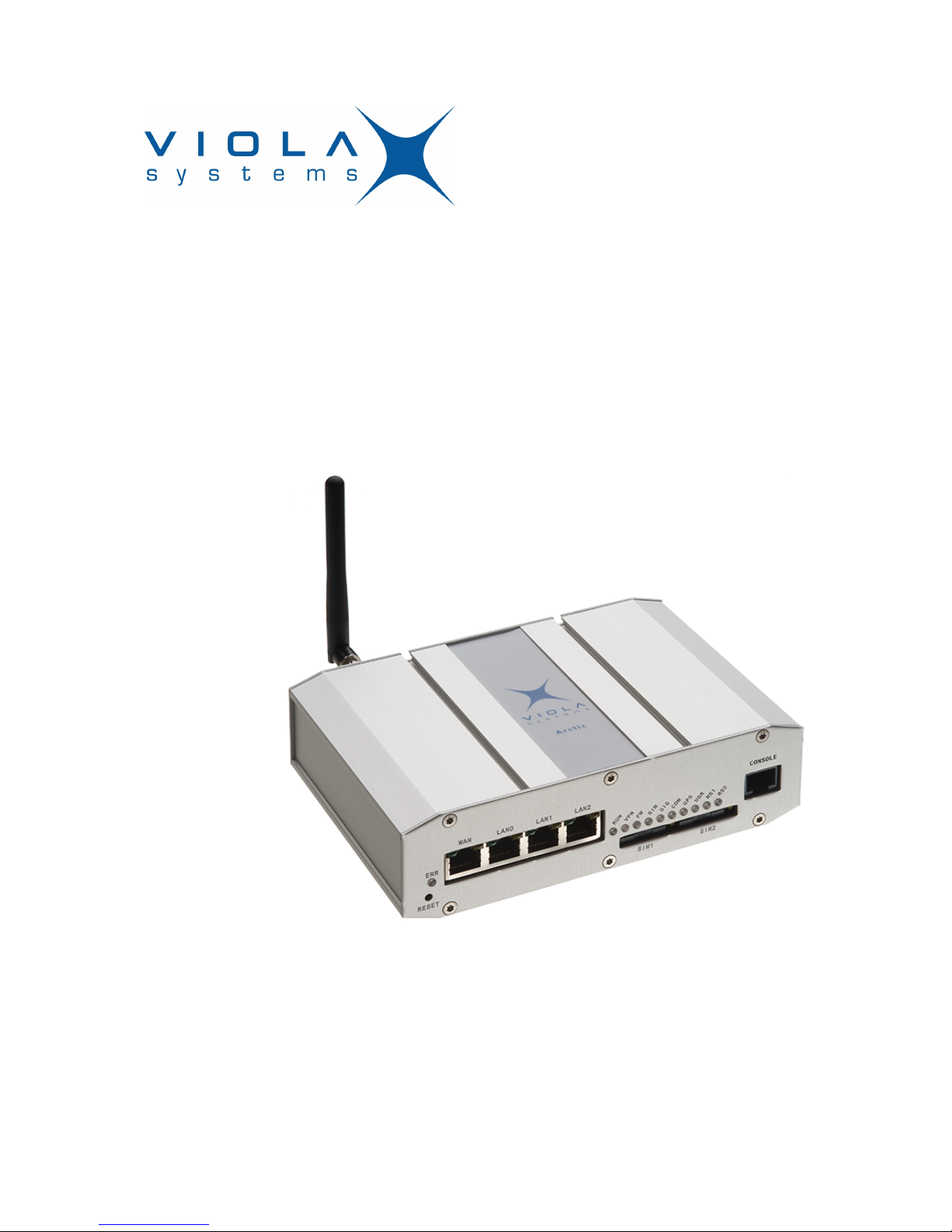
1.1 About the Arctic Substation Gateway
The Arctic Substation Gateway product is an industrial grade wireless router
for demanding IP connectivity applications.
1.2 Arctic Substation Gateway features
Arctic Substation Gateway offers different advanced features. Flexible design
allows the system to gain extra features if required.
High speed wireless connectivity
Arctic Substation Gateway has support for the latest mobile technologies,
such as HSPA+ in 3G network. This allows the remote control of wide
bandwidth services such as video surveillance or high amount of
measurement and control channels.
Flexible routing
Arctic Substation Gateway can be configured to fit in all kinds of networks.
It also has full support for Serial - Ethernet routing of industrial network
protocols.
High security
Arctic Substation Gateway has highly configurable firewall and secure VPN
support for secured connectivity.
Redundancy and reliability
Arctic Substation Gateway offers redundancy against network breakdowns
and remote VPN endpoint breakdowns. This allows the overall system
to achieve high availability numbers. These functionalities added to high
reliability of both the hardware and software make very robust system suitable
in harsh and demanding industrial environments.
Remote management
Arctic Substation Gateway can be managed remotely and it is easy to move
configurations between units.
1.3 Packaging information
The product package should contain the following items:
■
3-pin power connector
■
Antenna
■
Arctic Substation Gateway
User Manual
Arctic Substation Gateway
Firmware Version 2.4.x 10 Document Version 1
2 Hardware description
This section describes the physical interfaces on Arctic Substation Gateway.
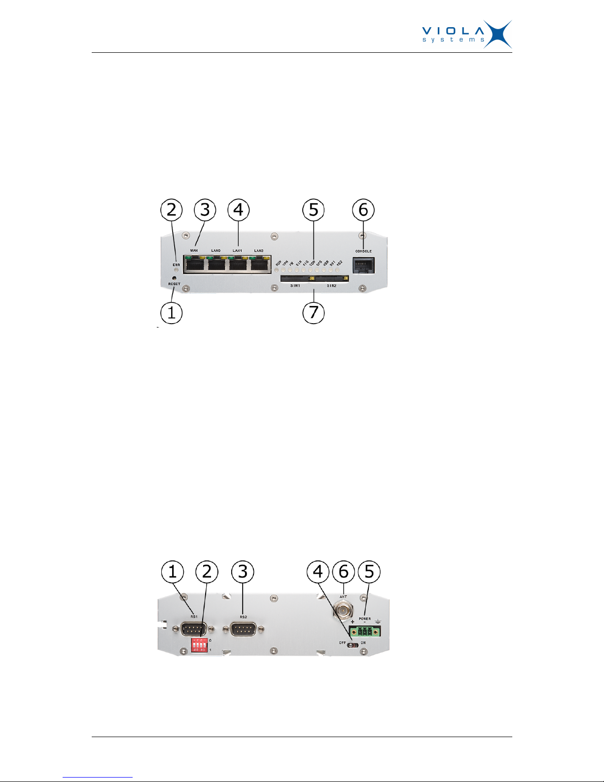
2.1 Front panel
Arctic Substation Gateway front panel is shown in the figure below.
Figure 1. Front Panel
LEDs and switches (from left to right) with section reference to more detailed
information:
1. Reset button (Power switch and reset button on page 16)
2. Error LED (section LEDs on page 11)
3. Ethernet WAN port (section Ethernet WAN on page 12)
4. Ethernet LAN ports (section Ethernet LAN)
5. LEDs (section LEDs on page 11)
6. Serial console port (section Serial console port on page 13)
7. SIM card slots (section SIM card slots on page 16)
2.2 Back Panel
Arctic Substation Gateway back panel is shown in the figure below.
Figure 2. Back Panel
Connectors (from left to right):
User Manual
Arctic Substation Gateway
Firmware Version 2.4.x 11 Document Version 1
1. Serial port 1 (section Serial port 1 on page 14)
2. Serial port 1 configuration DIP switches (section Serial port 1 on page
14)
3. Serial port 2 (section Serial port 2 on page 15)
4. Power switch
5. Power connector (section Power connector on page 16)
6. Antenna connector (section Antenna connector on page 16)
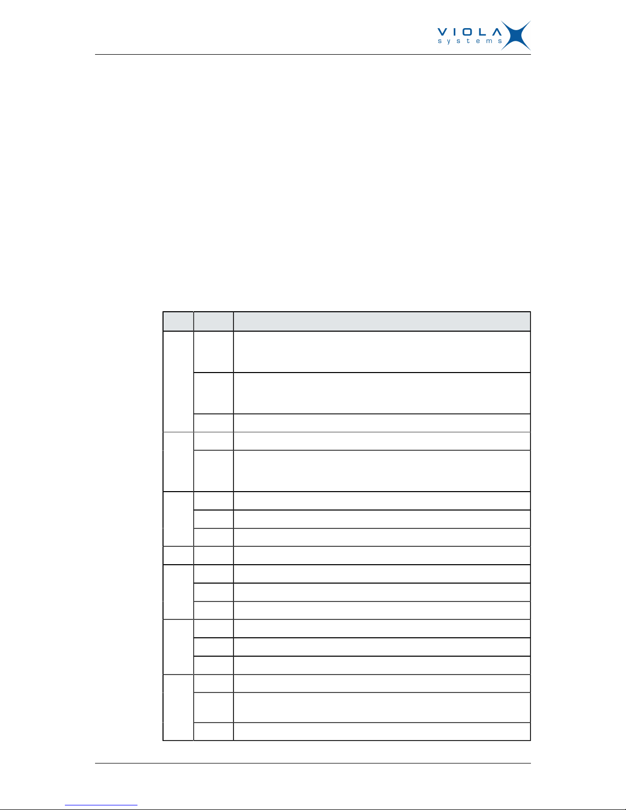
2.3 LEDs
2.3.1 Status LEDs
Arctic Substation Gateway has 11 status LEDs. They are located on the front
panel (see section Front panel).
Table 1: LED Description
LED State Meaning
On Unit is restarting. LED should turn off after restart (usually about 30
seconds). If the LED is constantly turned on for a long time, contact
technical support.
Blinking There is something wrong with the unit or the power supply causes
the unit to restart constantly. Try with another power supply and if
that does not help, contact technical support.
Error
Off Unit is operating normally.
Blinking Unit is operating normallyRUN
Off If the unit is turned on and RUN led is not blinking, the system has
catched an error and is waiting for restart. The unit should restart
soon.
On VPN connection is up
Blinking VPN connection is starting
VPN
Off VPN connection is disabled
FW - Reserved for future use
On SIM card has been found and it is ready for use.
Blinking SIM card initialization is in progress.
SIM
Off SIM card is not in use
On Signal level is normal or good (better than -95 dBm)
Blinking Signal level is weak (between -110 dBm and -95 dBm)
SIG
Off There is no signal (below -110 dBm)
On Connection is up
Blinking Connection is starting. If the connection is not coming up, check the
SIM and SIG LEDs
COM
Off Connection is stopped
User Manual
Arctic Substation Gateway
Firmware Version 2.4.x 12 Document Version 1
LED State Meaning
APP - Reserved for future use
USR - Reserved for future use
RS1 - Reserved for future use
RS2 - Reserved for future use
2.3.2 Ethernet LEDs
All Ethernet ports have two LEDs to indicate the ports link and activity status.
Table 2: Ethernet LED description
LED State Meaning
On Link on
Blink Data received
Green
Off Link off
On Full duplexYellow
Off Half duplex
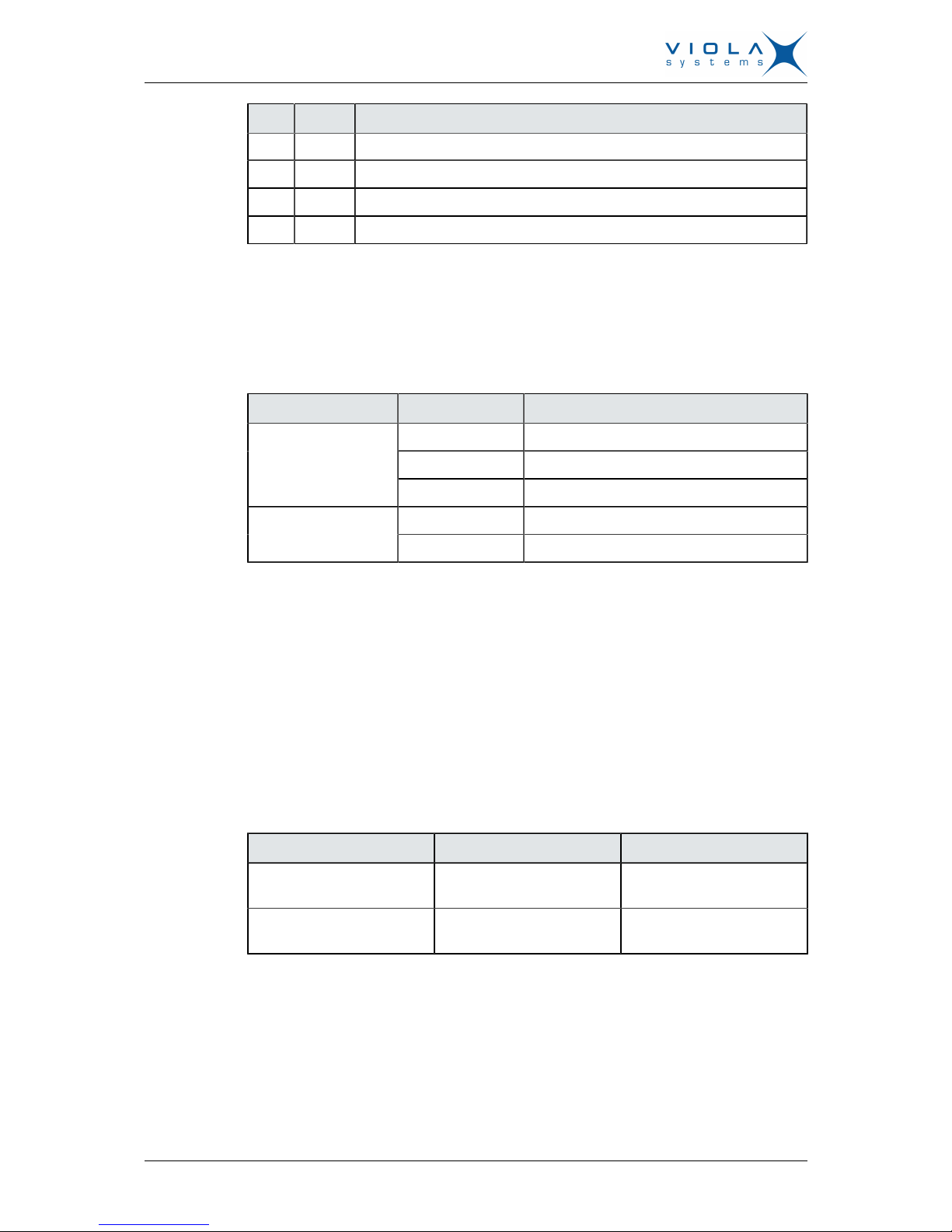
2.4 Networking
2.4.1 Mobile WAN
Arctic Substation Gateway has a high speed wireless functionality which
allows the use of bandwidth demanding wireless applications. Arctic
Substation Gateway supports wireless data speeds up to 7.2 Mbit/s, however
the practical data transfer rates depend on selected wireless network and
network capacity.
Table 3: Mobile WAN specifications
Networks Frequencies Maximum data rates
UMTS with HSUPA (cat
11/12)
850/900/1900/2100 MHz 7.2 Mbit/s downlink / 5.76
Mbit/s uplink
EDGE / GPRS class 10 850/900/1800/1900 MHz 216 kbps downlink/ 108
kbps uplink
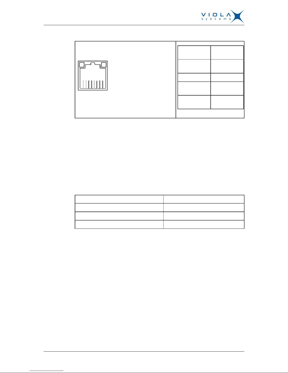
2.4.2 Ethernet WAN
Arctic Substation Gateway has one physical port for Ethernet WAN.
Specifications are shown in the table below.
User Manual
Arctic Substation Gateway
Firmware Version 2.4.x 13 Document Version 1
Table 4: Ethernet WAN specifications
Figure 3. Connector
Number of
ports
1
Speed 10Base-T,
100Base-TX
Duplex Half and Full
Auto-
negotiation
Yes
Recommended
cabling
Cat5 or better
If Ethernet WAN interface is directly connected to computer, crossover cable
must be used. Ethernet WAN interface does not support automatic MDI/MDIX
detection.
2.4.3 Ethernet LAN
Arctic Substation Gateway has three physical ports for Ethernet LAN. These
ports are connected to a common switch. Specifications are shown in the table
below.
Table 5: Ethernet LAN Specifications
Speed 10Base-T, 100Base-TX
Duplex Half and Full
Auto-negotiation Yes
Recommended cabling Cat5 or better
If Ethernet LAN interface is directly connected to computer, both crossover
and straight cables can be used. Ethernet LAN interface supports automatic
MDI/MDIX detection.
2.5 Serial ports
Arctic Substation Gateway has two application serial ports and one serial
console port. The application serial ports have the following differences:
■
Serial port 1 is configurable to multiple serial formats (RS-232/422/485).
■
Serial port 2 supports only RS-232 data mode.
The serial port connectors are 9-pin D-sub (male) connectors. Serial ports
enact as DTE devices.
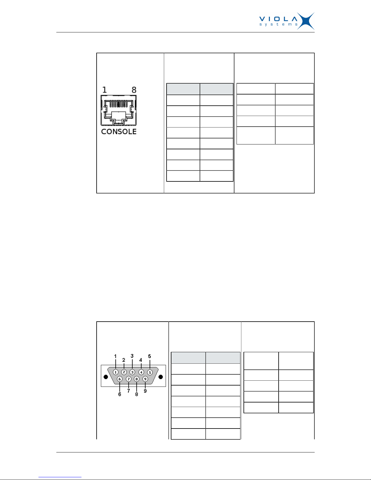
2.5.1 Serial console port
Serial console connector is located in Arctic Substation Gateway front panel.
The connector type is RJ45. The connector is described in the table below.
User Manual
Arctic Substation Gateway
Firmware Version 2.4.x 14 Document Version 1
Table 6: Serial console
Figure 4. Connector
diagram
Table 7: Connector
pinout
Pin Function
1 CTS
2 DSR
3 RXD
4 GND
5 GND
6 TXD
7 DTR
8 RTS
Table 8: Serial port
configuration
Baud rate 115200
Data bits 8
Parity No parity
Stop bits 1
Flow control No flow
control
Console port can be connected from a PC by using a Cisco compatible serial
console cable.
Ethernet serial console adapters are available from Viola Systems. They
allow serial console access with the adapter and straight Ethernet cable. Viola
Systems order code is 3170. Contact the local sales office for more details.
To open serial console access a terminal program is needed. Recommended
terminal programs are Tera Term and Putty. Open the connection using
Ethernet LAN settings.
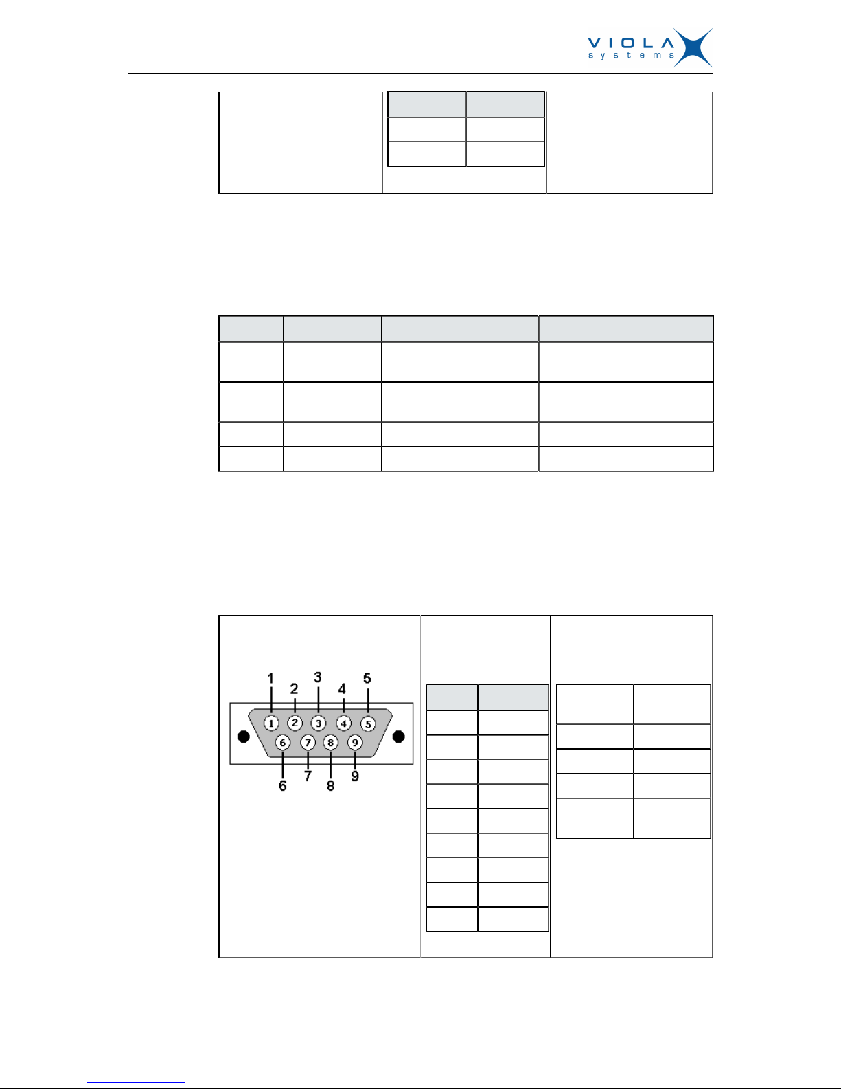
2.5.2 Serial port 1
Serial port 1 is configurable to multiple serial formats (RS-232/422/485).
Table 9: Serial port 1
Figure 5. Connector
diagram
Table 10: Connector
pinout (RS-232 mode)
Pin Function
1 DCD
2 RXD
3 TXD
4 DTR
5 GND
6 DSR
7 RTS
Table 11: Serial port
configuration
Baud rate 115 -
230400
Data bits 8
Parity No parity
Stop bits 1
Flow control CTS/RTS
User Manual
Arctic Substation Gateway
Firmware Version 2.4.x 15 Document Version 1
Pin Function
8 CTS
9 RI
DIP switch configuration for serial port 1 is described in table 12. By default all
are set to "0" position (RS-232 mode). DIP switches 2-4 apply only when port
is set in RS-485 mode (DIP switch 1 on "1" position).
Table 12: Serial port 1 DIP switches
Number Function State Explanation
1 RS-232 /
RS-485
0 = RS-232, 1 = RS-485 Selects serial port operation
mode
2 FULL / HALF 0 = FULL, 1 = HALF Selects between half ( 2-
wire) and full duplex (4-wire)
3 BIAS 0 = OFF, 1 = ON RS-485 biasing
4 TERMINATION 0 = OFF, 1 = ON RS-485 termination
Serial port pinouts in RS-422 and RS-485 modes are described in the table
below.
2.5.3 Serial port 2
Table 13: Serial port 2
Figure 6. Connector diagram Table 14:
Connector pinout
Pin Function
1 DCD
2 RXD
3 TXD
4 DTR
5 GND
6 DSR
7 RTS
8 CTS
9 RI
Table 15: Serial port
configuration
Baud rate 115 -
230400
Data bits 8
Parity No parity
Stop bits 1
Flow
control
No flow
control
Serial port 2 supports only RS-232 data mode.
User Manual
Arctic Substation Gateway
Firmware Version 2.4.x 16 Document Version 1
2.6 Power switch and reset button
Power switch is located on the back panel. It turns the unit on and off.
Reset button is located on the front panel. Press shortly to reset the unit.
Reset button can be used to restore factory default settings. To restore factory
default settings, reset the unit by keeping the reset button pressed down until
all the status LEDs blink. This indicates the factory presets have been applied.
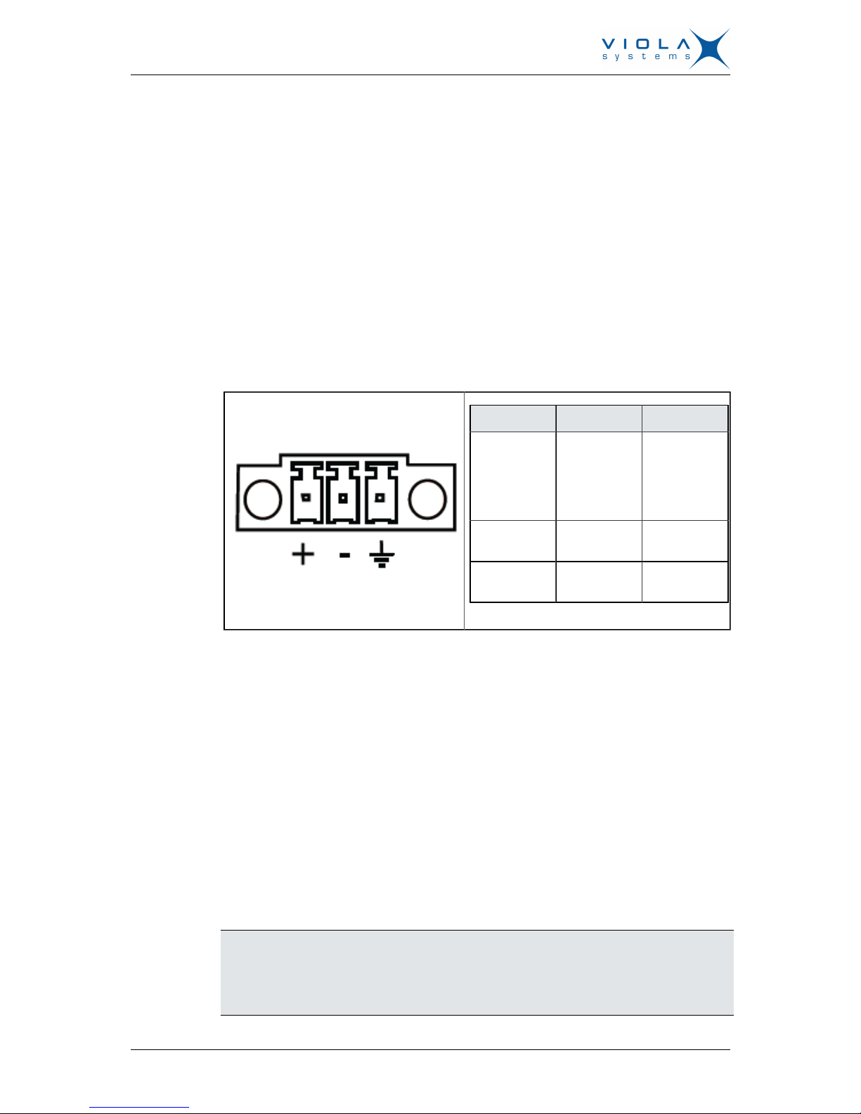
2.7 Power connector
Arctic Substation Gateway has a 3-pin power connector. Pinout and voltage
limits are described in the table below. Supplied plug type is Phoenix Contact
MC 1,5 / 3-STF-3,5 with screw fastening.
Table 16: Power supply connector
Figure 7. Connector
Pin Symbol Function
1 + Voltage in,
positive /
11 ... 18
VDC, 400
mA
2 - Voltage in,
negative
3 GND Extra ground
connection
Arctic Substation Gateway can be also used with 2-pin power connector, pin
3 left unconnected. The unit is protected against reversed polarity within the
limits of the specified voltages.
Viola Systems default power supply for Arctic Substation Gateway can be
ordered with order code 3020. Note that the power supply is not included in
standard Arctic Substation Gateway package.
2.8 Antenna connector
The Arctic Substation Gateway has a FME antenna connector (male type) for
an external antenna. It is possible to use any kind of external 50 Ω quad-band
antenna.
2.9 SIM card slots
Note!
Do not insert or remove the SIM card while the Arctic Substation Gateway
is in operation. The SIM card contents may become corrupted if the card is
removed while data is being written to it.
 Loading...