

Viola Systems arctic c-1220, arctic c-1240, arctic c-1260, arctic c-1230 User Manual
Arctic C-Series User Manual
Arctic Communication Gateway (C-1220, C-1230, C-1240, C-1260)
Firmware Version 3.1.5
Document Version 1.0
May 2015

User's Manual
Arctic Communication Gateway
Firmware Version 3.1.5 2 Document Version 1.0
Copyright and Trademark
Copyright © 2008-2015, Viola Systems Ltd. All rights to this manual are owned
solely by Viola Systems Ltd. (referred elsewhere in this User’s Manual as
Viola Systems). All rights reserved. No part of this manual may be transmitted
or reproduced in any form or by any means without a prior written permission
from Viola Systems.
Viola Systems Ltd.
Lemminkäisenkatu 14-18 B
FI-20520 Turku
Finland
E-mail: info@violasystems.com
Technical Support
Phone: +358 20 1226 226
Fax: +358 20 1226 220
E-mail: support@violasystems.com
Internet: http://www.violasystems.com

User's Manual
Arctic Communication Gateway
Firmware Version 3.1.5 3 Document Version 1.0
Disclaimer
Viola Systems reserves the right to change the technical specifications
or functions of its products or to discontinue the manufacture of any of its
products or to discontinue the support of any of its products without any
written announcement and urges its customers to ensure that the information
at their disposal is valid.
Viola software and programs are delivered “as is”. The manufacturer does not
grant any kind of warranty including guarantees on suitability and applicability
to a certain application. Under no circumstance is the manufacturer or the
developer of a program responsible for any damage possibly caused by the
use of a program. The names of the programs as well as all copyrights relating
to the programs are the sole property of Viola Systems. Any transfer, licensing
to a third party, leasing, renting, transportation, copying, editing, translating,
modifying into another programming language or reverse engineering for any
intent is forbidden without the written consent of Viola Systems.
Viola Systems has attempted to verify that the information in this manual is
correct with regard to the state of products and software on the publication
date of the manual. We assume no responsibility for possible errors which
may appear in this manual. Information in this manual may change without
prior notice from Viola Systems.

User's Manual
Arctic Communication Gateway
Firmware Version 3.1.5 4 Document Version 1.0
Declaration of Conformity
(according to ISO/IEC Guide 22 and EN 45014)
Manufacturer’s Name: Viola Systems Ltd.
Manufacturer’s Address:
Lemminkäisenkatu 14-18 B
FI-20520 Turku
Finland
declares that this product:
Product Name:
Arctic Communication Gateway
conforms to the following standards:
EMC:
IEC 61850-3 (Edition 2.0 2013-12)
1. CISPR 16-2-3: Radiated Disturbance
2. CISPR 16-2-1: Conducted Disturbance
IEC 61850-3 Immunity Tests
1. EN 61000-4-2 (2008-12): Electrostatic Discharge (ESD)
2. EN 61000-4-3 (2006-02): Radiated Radio-Frequency Electromagnetic Field
3. EN 61000-4-4 (2012-04): Electrical Fast Transient (EFT)
4. EN 61000-4-5 (2005-11): Surge
5. EN 61000-4-6 (2008-10): Conducted Radio-Frequency Electromagnetic
Field
Supplementary Information:
“The product complies with the requirements of the Low Voltage Directive
73/23/EEC and EMC directive 89/336/EEC.”
Note!
This is a Class A product. In a domestic environment this product may cause
radio Interference which may make it necessary for the user to take adequate
measures.
Manufacturer’s Contact Information:
Viola Systems Ltd.
Lemminkäisenkatu 14-18 B
FI-20520 Turku
Finland
Phone: +358 20 1226 226
Fax: +358 20 1226 220

User's Manual
Arctic Communication Gateway
Firmware Version 3.1.5 5 Document Version 1.0
Warranty and Safety Instructions
Read these safety instructions carefully before using the products mentioned
in this manual:
Warranty will be void if the product is used in any way in contradiction with the
instructions given in this manual or if the product has been tampered with.
The devices mentioned in this manual are to be used only according to the
instructions described in this manual. Faultless and safe operation of the
devices can be guaranteed only if the transport, storage, operation and
handling of the devices is appropriate. This also applies to the maintenance of
the products.
To prevent damage both the product and any terminal devices must always
be switched OFF before connecting or disconnecting any cables. It should
be ascertained that different devices used have the same ground potential.
Before connecting any power cables the output voltage of the power supply
should be checked.
This product is not fault-tolerant and is not designed, manufactured
or intended for use or resale as on-line control equipment or as part
of such equipment in any hazardous environment requiring fail- safe
performance, such as in the operation of nuclear facilities, aircraft navigation
or communication systems, air traffic control, direct life support machines,
or weapons systems, in which the failure of Viola Systems manufactured
hardware or software could lead directly to death, personal injury, or severe
physical or environmental damage.

User's Manual
Arctic Communication Gateway
Firmware Version 3.1.5 6 Document Version 1.0
Revisions
Date Document version Firmware version Description of
changes
05/2015 1.0 Manual released

User's Manual
Arctic Communication Gateway
Firmware Version 3.1.5 7 Document Version 1.0
Contents
COPYRIGHT AND TRADEMARK ........................................................................................2
DISCLAIMER..........................................................................................................................3
DECLARATION OF CONFORMITY......................................................................................4
WARRANTY AND SAFETY INSTRUCTIONS.......................................................................5
REVISIONS............................................................................................................................6
1. INTRODUCTION............................................................................................................... 9
1.1 About this User’s Manual......................................................................................................9
1.2 Arctic C-series – Communication Gateways.........................................................................9
2. PHYSICAL INTERFACES...............................................................................................10
2.1 Front Panel Description.......................................................................................................10
2.2 Back Panel Description.......................................................................................................13
2.3 Side Panel Description........................................................................................................14
2.4 Product Information Label ..................................................................................................15
2.5 Firmware Version................................................................................................................ 15
3. QUICK INSTALLATION...................................................................................................16
3.1 Connection Principle............................................................................................................16
3.2 Connecting cables...............................................................................................................16
3.3 Logging in to Arctic.............................................................................................................16
3.4 Setting Ethernet port function to LAN.................................................................................18
3.5 Configuring Mobile WAN (cellular network interface).........................................................19
3.6 Configuring default gateway................................................................................................19
4. NETWORK CONFIGURATION.......................................................................................21
4.1 Configuration screens..........................................................................................................21
4.1.1 Host and domain names.........................................................................................21
4.1.2 Ethernet WAN......................................................................................................... 21
4.1.3 Mobile WAN............................................................................................................ 22
4.1.4 WAN Failover and backup routing settings............................................................ 23
4.1.5 Ethernet LAN...........................................................................................................24
4.1.6 Network monitor......................................................................................................24
4.2 Routing.................................................................................................................................25
4.2.1 Routing parameters.................................................................................................25
4.2.2 Default route............................................................................................................26
4.2.3 WAN redundancy/failover........................................................................................26
4.2.4 Routing serial <-> Ethernet.....................................................................................26
4.3 Network services.................................................................................................................26
4.3.1 DNS proxy...............................................................................................................26
4.4 Network status information..................................................................................................26
4.4.1 System status screen..............................................................................................26
4.4.2 Mobile WAN status LEDs.......................................................................................27
4.4.3 Modem info screen................................................................................................. 27
5. SERIAL PORT CONFIGURATION................................................................................. 29
5.1 Configuring a serial port......................................................................................................29
5.2 Configuring serial gateway..................................................................................................29

User's Manual
Arctic Communication Gateway
Firmware Version 3.1.5 8 Document Version 1.0
6. ADDITIONAL SYSTEM CONFIGURATION....................................................................30
6.1 Changing system password................................................................................................30
6.2 Date and time......................................................................................................................30
6.3 System log...........................................................................................................................31
6.4 Factory default settings.......................................................................................................31
6.5 Firmware update..................................................................................................................31
6.6 Configuration profiles...........................................................................................................31
7. TROUBLESHOOTING.....................................................................................................33
SPECIFICATIONS .............................................................................................................. 34
LIMITED WARRANTY......................................................................................................... 36
TECHNICAL SUPPORT .....................................................................................................37
User's Manual
Arctic Communication Gateway
Firmware Version 3.1.5 9 Document Version 1.0
1 Introduction
1.1 About this User’s Manual
This User’s Manual describes the operation of the Arctic Communication
Gateway. All devices in this User’s Manual are referred to as Arctic, unless
otherwise mentioned. This manual provides introductory information as well
as detailed instructions on how to set up and manage the Arctic as part of
a network environment. It is intended for anyone involved in installing and
managing Arctic devices. It is assumed that the reader of this manual is
familiar with basic working principles of Internet technology.
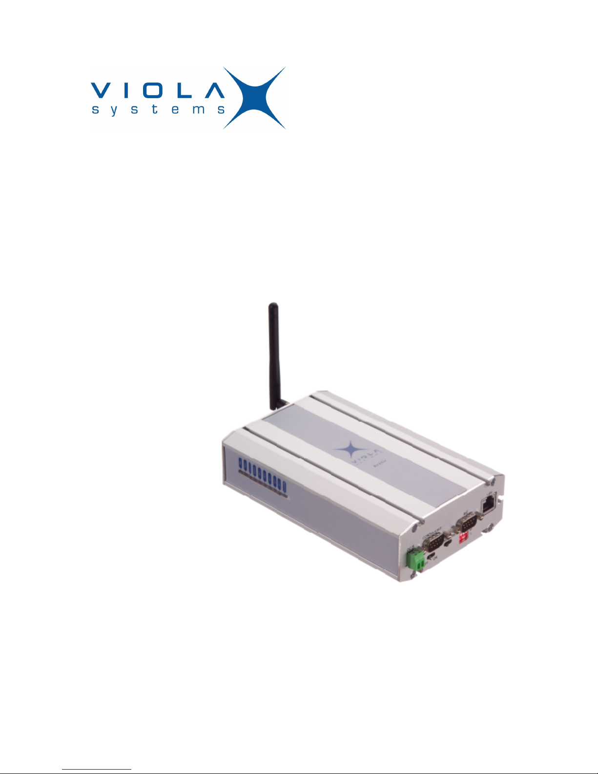
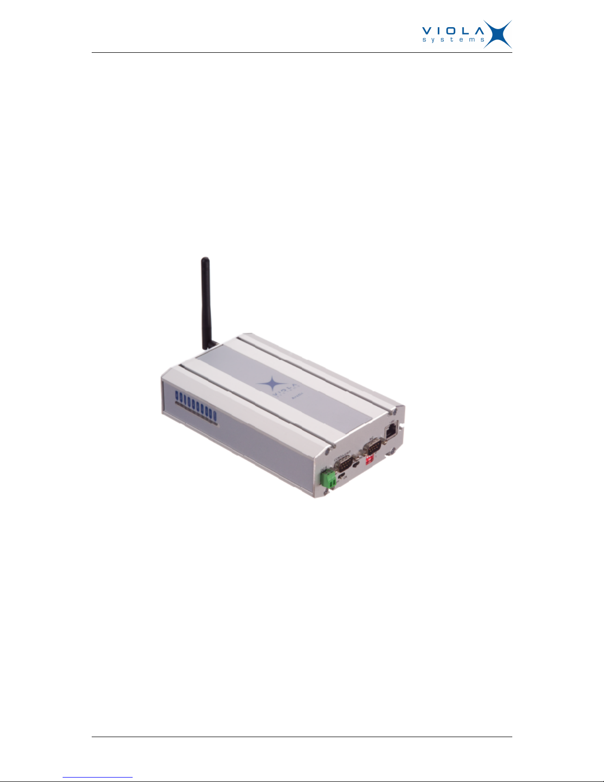
Figure 1. Arctic Communication Gateway
1.2 Arctic C-series – Communication Gateways
The Arctic C-series product family includes a number of Arctic communication
gateway product variants. Arctic communication gateways provide highly
robust network components for rugged industrial environments, ease of use,
and proven long-term field operation. Arctic C–series products provide total
solutions when the aim is to integrate remote serial (RS232/485) or Ethernet
devices within a central management system over a GPRS, 3G or LTE
connection. The Arctic C–series products wireless gateways make it possible
to have cost-effective communication networks over long distances, at high
data rates (up to 100 Mbps).
User's Manual
Arctic Communication Gateway
Firmware Version 3.1.5 10 Document Version 1.0
2 Physical Interfaces
The Arctic unit contains three panels for interface connections and status
indication.
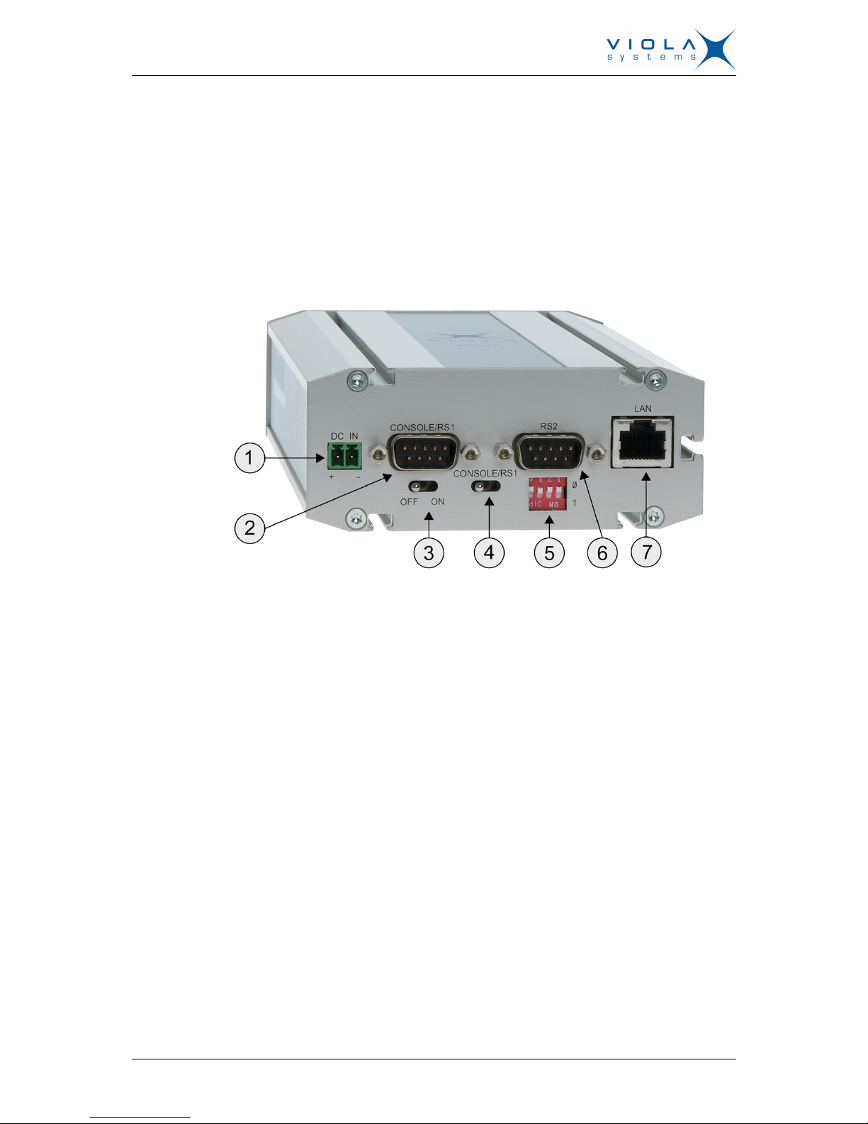
2.1 Front Panel Description
The front panel of the Arctic consists of the following connectors and switches:
Figure 2. Front Panel Description
1. Power supply connector
2. Console serial port (RS1)
3. Power switch
4. Console switch
5. DIP switches
6. Application serial port (RS2)
7. Ethernet connector
The Arctic has rails to enable wall or DIN rail mounting. The front panel
contains slots for nuts or other mounting accessories (optional) in order to gain
access to these rails.
Power Supply Connector
The Arctic has a VDC power supply connector as shown in the figure below.

User's Manual
Arctic Communication Gateway
Firmware Version 3.1.5 11 Document Version 1.0
Figure 3. Power supply connector
■
Pin 1 is positive (+)
■
Pin 2 is negative (–)
The unit is protected against reversed polarity in specified voltage range.
Power Switch
Enables or disables the operation of the Arctic.
Console Enable Switch
Enables or disables console access. When it is disabled, both serial ports may
be used as an application serial port. When the switch is in the right position,
RS1 is in serial port mode and when in the left position, RS1 is in console
mode.
DIP Switches
It selects an application port (RS-2) mode and settings (RS-232 or RS-485).
By default all are set to “0” when the port is acting as an RS-232. DIP switches
2-4 apply only when RS-485 mode is selected by DIP switch 1.
Table 1: DIP Switches
Number Function State Explanation
1 RS-232/RS-485
“0” = RS-232
”1” = RS-485
Selects RS-port operation
2 HALF/FULL
“0” = full
“1” = half
Selects between half-duplex (2-wire)
and full-duplex (4-wire)
3 BIAS
“0” = OFF
“1” = ON
RS-485 biasing
4 TERMINATION
“0” = OFF
“1” = ON
RS-485 termination
Serial Ports (RS-232, RS-422/485 -connectors)
Arctic has two serial port connectors. These are 9-pin male connectors (DB9).
A null modem cable (product code: 3100) may be used to connect the Arctic
to a PC. The Arctic supports CTS/RTS flow control. The figure of Arctic’s DB9
(DTE) Male connector is shown in the figure below.

User's Manual
Arctic Communication Gateway
Firmware Version 3.1.5 12 Document Version 1.0
Figure 4. DB9 male connector
The serial port 1 (RS1) is a full RS-232 port. The pin description of this port is
as follows:
Table 2: RS-232 Port PIN Description
Pin Number Name Direction Explanation
1 DCD IN Data Carrier Detect
2 RXD IN Received Data
3 TXD OUT Transmitted Data
4 DTR OUT Data Terminal Ready. Handshake output
5 GND - Signal ground.
6 DSR IN Data Set Ready. Handshake input
7 RTS OUT Ready To Send. Handshake output
8 CTS IN Clear To Send. Handshake input
9 RI IN Ring Indicator
The serial port 2 (RS2) can be configured either as a half RS-232 or an
RS-422/485 (DTE Master). The Pin description is same as in RS1, when in
RS-232 mode. The pin description of this port is as follows in RS-485 mode.
Table 3: RS-485 Port PIN Description
Pin Number RS-485,Full duplex (4-wire) RS-485 Half duplex (2-wire)
1 NC NC
2 RXD+ (in) NC
3 TXD–(out) TXD/RXD- (out/in)
4 NC NC
5 GND GND
6 NC NC
7 TXD+ (out) TXD/RXD+ (out/in)
8 RXD–(in) NC
9 NC NC
Note!
Make sure that you DO NOT connect RS-422 or RS-485 devices to a port
which has been configured to operate as an RS-232 port.
Ethernet Connector
Arctic has an RJ45 connector for 10/100 Mbps Ethernet connection. Maximum
length of the Ethernet cable is 100m.
 Loading...