

Page 1
Arctic C-Series User Manual
Arctic Communication Gateway (C-1220, C-1230, C-1240, C-1260)
Firmware Version 3.1.5
Document Version 1.0
May 2015
Page 2

User's Manual
Arctic Communication Gateway
Firmware Version 3.1.5 2 Document Version 1.0
Copyright and Trademark
Copyright © 2008-2015, Viola Systems Ltd. All rights to this manual are owned
solely by Viola Systems Ltd. (referred elsewhere in this User’s Manual as
Viola Systems). All rights reserved. No part of this manual may be transmitted
or reproduced in any form or by any means without a prior written permission
from Viola Systems.
Viola Systems Ltd.
Lemminkäisenkatu 14-18 B
FI-20520 Turku
Finland
E-mail: info@violasystems.com
Technical Support
Phone: +358 20 1226 226
Fax: +358 20 1226 220
E-mail: support@violasystems.com
Internet: http://www.violasystems.com
Page 3

User's Manual
Arctic Communication Gateway
Firmware Version 3.1.5 3 Document Version 1.0
Disclaimer
Viola Systems reserves the right to change the technical specifications
or functions of its products or to discontinue the manufacture of any of its
products or to discontinue the support of any of its products without any
written announcement and urges its customers to ensure that the information
at their disposal is valid.
Viola software and programs are delivered “as is”. The manufacturer does not
grant any kind of warranty including guarantees on suitability and applicability
to a certain application. Under no circumstance is the manufacturer or the
developer of a program responsible for any damage possibly caused by the
use of a program. The names of the programs as well as all copyrights relating
to the programs are the sole property of Viola Systems. Any transfer, licensing
to a third party, leasing, renting, transportation, copying, editing, translating,
modifying into another programming language or reverse engineering for any
intent is forbidden without the written consent of Viola Systems.
Viola Systems has attempted to verify that the information in this manual is
correct with regard to the state of products and software on the publication
date of the manual. We assume no responsibility for possible errors which
may appear in this manual. Information in this manual may change without
prior notice from Viola Systems.
Page 4

User's Manual
Arctic Communication Gateway
Firmware Version 3.1.5 4 Document Version 1.0
Declaration of Conformity
(according to ISO/IEC Guide 22 and EN 45014)
Manufacturer’s Name: Viola Systems Ltd.
Manufacturer’s Address:
Lemminkäisenkatu 14-18 B
FI-20520 Turku
Finland
declares that this product:
Product Name:
Arctic Communication Gateway
conforms to the following standards:
EMC:
IEC 61850-3 (Edition 2.0 2013-12)
1. CISPR 16-2-3: Radiated Disturbance
2. CISPR 16-2-1: Conducted Disturbance
IEC 61850-3 Immunity Tests
1. EN 61000-4-2 (2008-12): Electrostatic Discharge (ESD)
2. EN 61000-4-3 (2006-02): Radiated Radio-Frequency Electromagnetic Field
3. EN 61000-4-4 (2012-04): Electrical Fast Transient (EFT)
4. EN 61000-4-5 (2005-11): Surge
5. EN 61000-4-6 (2008-10): Conducted Radio-Frequency Electromagnetic
Field
Supplementary Information:
“The product complies with the requirements of the Low Voltage Directive
73/23/EEC and EMC directive 89/336/EEC.”
Note!
This is a Class A product. In a domestic environment this product may cause
radio Interference which may make it necessary for the user to take adequate
measures.
Manufacturer’s Contact Information:
Viola Systems Ltd.
Lemminkäisenkatu 14-18 B
FI-20520 Turku
Finland
Phone: +358 20 1226 226
Fax: +358 20 1226 220
Page 5

User's Manual
Arctic Communication Gateway
Firmware Version 3.1.5 5 Document Version 1.0
Warranty and Safety Instructions
Read these safety instructions carefully before using the products mentioned
in this manual:
Warranty will be void if the product is used in any way in contradiction with the
instructions given in this manual or if the product has been tampered with.
The devices mentioned in this manual are to be used only according to the
instructions described in this manual. Faultless and safe operation of the
devices can be guaranteed only if the transport, storage, operation and
handling of the devices is appropriate. This also applies to the maintenance of
the products.
To prevent damage both the product and any terminal devices must always
be switched OFF before connecting or disconnecting any cables. It should
be ascertained that different devices used have the same ground potential.
Before connecting any power cables the output voltage of the power supply
should be checked.
This product is not fault-tolerant and is not designed, manufactured
or intended for use or resale as on-line control equipment or as part
of such equipment in any hazardous environment requiring fail- safe
performance, such as in the operation of nuclear facilities, aircraft navigation
or communication systems, air traffic control, direct life support machines,
or weapons systems, in which the failure of Viola Systems manufactured
hardware or software could lead directly to death, personal injury, or severe
physical or environmental damage.
Page 6

User's Manual
Arctic Communication Gateway
Firmware Version 3.1.5 6 Document Version 1.0
Revisions
Date Document version Firmware version Description of
changes
05/2015 1.0 Manual released
Page 7

User's Manual
Arctic Communication Gateway
Firmware Version 3.1.5 7 Document Version 1.0
Contents
COPYRIGHT AND TRADEMARK ........................................................................................2
DISCLAIMER..........................................................................................................................3
DECLARATION OF CONFORMITY......................................................................................4
WARRANTY AND SAFETY INSTRUCTIONS.......................................................................5
REVISIONS............................................................................................................................6
1. INTRODUCTION............................................................................................................... 9
1.1 About this User’s Manual......................................................................................................9
1.2 Arctic C-series – Communication Gateways.........................................................................9
2. PHYSICAL INTERFACES...............................................................................................10
2.1 Front Panel Description.......................................................................................................10
2.2 Back Panel Description.......................................................................................................13
2.3 Side Panel Description........................................................................................................14
2.4 Product Information Label ..................................................................................................15
2.5 Firmware Version................................................................................................................ 15
3. QUICK INSTALLATION...................................................................................................16
3.1 Connection Principle............................................................................................................16
3.2 Connecting cables...............................................................................................................16
3.3 Logging in to Arctic.............................................................................................................16
3.4 Setting Ethernet port function to LAN.................................................................................18
3.5 Configuring Mobile WAN (cellular network interface).........................................................19
3.6 Configuring default gateway................................................................................................19
4. NETWORK CONFIGURATION.......................................................................................21
4.1 Configuration screens..........................................................................................................21
4.1.1 Host and domain names.........................................................................................21
4.1.2 Ethernet WAN......................................................................................................... 21
4.1.3 Mobile WAN............................................................................................................ 22
4.1.4 WAN Failover and backup routing settings............................................................ 23
4.1.5 Ethernet LAN...........................................................................................................24
4.1.6 Network monitor......................................................................................................24
4.2 Routing.................................................................................................................................25
4.2.1 Routing parameters.................................................................................................25
4.2.2 Default route............................................................................................................26
4.2.3 WAN redundancy/failover........................................................................................26
4.2.4 Routing serial <-> Ethernet.....................................................................................26
4.3 Network services.................................................................................................................26
4.3.1 DNS proxy...............................................................................................................26
4.4 Network status information..................................................................................................26
4.4.1 System status screen..............................................................................................26
4.4.2 Mobile WAN status LEDs.......................................................................................27
4.4.3 Modem info screen................................................................................................. 27
5. SERIAL PORT CONFIGURATION................................................................................. 29
5.1 Configuring a serial port......................................................................................................29
5.2 Configuring serial gateway..................................................................................................29
Page 8

User's Manual
Arctic Communication Gateway
Firmware Version 3.1.5 8 Document Version 1.0
6. ADDITIONAL SYSTEM CONFIGURATION....................................................................30
6.1 Changing system password................................................................................................30
6.2 Date and time......................................................................................................................30
6.3 System log...........................................................................................................................31
6.4 Factory default settings.......................................................................................................31
6.5 Firmware update..................................................................................................................31
6.6 Configuration profiles...........................................................................................................31
7. TROUBLESHOOTING.....................................................................................................33
SPECIFICATIONS .............................................................................................................. 34
LIMITED WARRANTY......................................................................................................... 36
TECHNICAL SUPPORT .....................................................................................................37
Page 9
User's Manual
Arctic Communication Gateway
Firmware Version 3.1.5 9 Document Version 1.0
1 Introduction
1.1 About this User’s Manual
This User’s Manual describes the operation of the Arctic Communication
Gateway. All devices in this User’s Manual are referred to as Arctic, unless
otherwise mentioned. This manual provides introductory information as well
as detailed instructions on how to set up and manage the Arctic as part of
a network environment. It is intended for anyone involved in installing and
managing Arctic devices. It is assumed that the reader of this manual is
familiar with basic working principles of Internet technology.
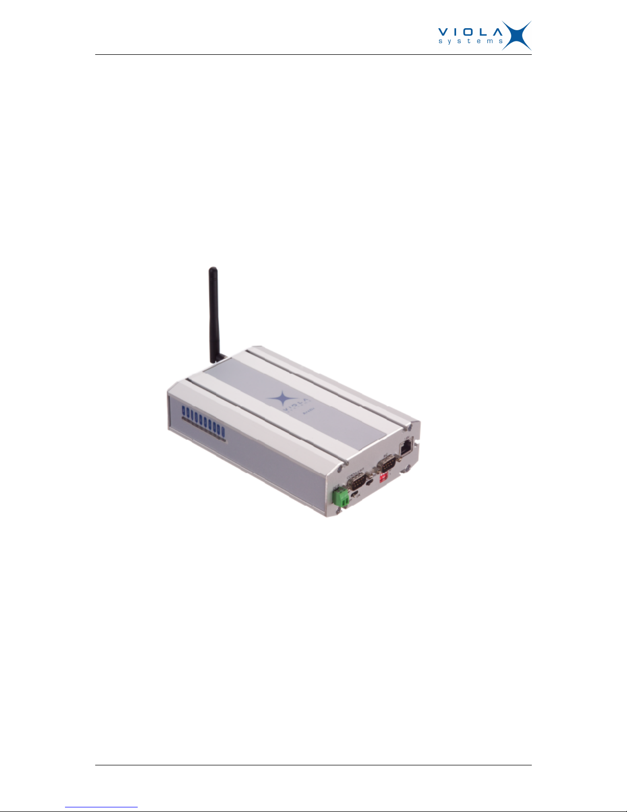
Figure 1. Arctic Communication Gateway
1.2 Arctic C-series – Communication Gateways
The Arctic C-series product family includes a number of Arctic communication
gateway product variants. Arctic communication gateways provide highly
robust network components for rugged industrial environments, ease of use,
and proven long-term field operation. Arctic C–series products provide total
solutions when the aim is to integrate remote serial (RS232/485) or Ethernet
devices within a central management system over a GPRS, 3G or LTE
connection. The Arctic C–series products wireless gateways make it possible
to have cost-effective communication networks over long distances, at high
data rates (up to 100 Mbps).
Page 10
User's Manual
Arctic Communication Gateway
Firmware Version 3.1.5 10 Document Version 1.0
2 Physical Interfaces
The Arctic unit contains three panels for interface connections and status
indication.
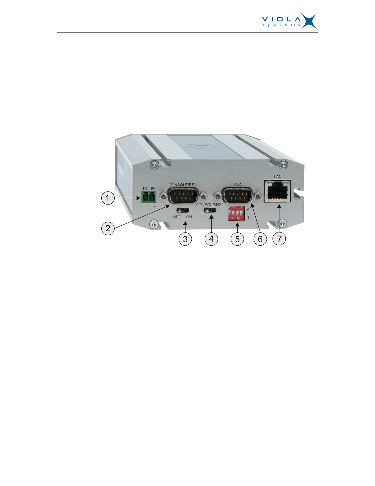
2.1 Front Panel Description
The front panel of the Arctic consists of the following connectors and switches:
Figure 2. Front Panel Description
1. Power supply connector
2. Console serial port (RS1)
3. Power switch
4. Console switch
5. DIP switches
6. Application serial port (RS2)
7. Ethernet connector
The Arctic has rails to enable wall or DIN rail mounting. The front panel
contains slots for nuts or other mounting accessories (optional) in order to gain
access to these rails.
Power Supply Connector
The Arctic has a VDC power supply connector as shown in the figure below.
Page 11

User's Manual
Arctic Communication Gateway
Firmware Version 3.1.5 11 Document Version 1.0
Figure 3. Power supply connector
■
Pin 1 is positive (+)
■
Pin 2 is negative (–)
The unit is protected against reversed polarity in specified voltage range.
Power Switch
Enables or disables the operation of the Arctic.
Console Enable Switch
Enables or disables console access. When it is disabled, both serial ports may
be used as an application serial port. When the switch is in the right position,
RS1 is in serial port mode and when in the left position, RS1 is in console
mode.
DIP Switches
It selects an application port (RS-2) mode and settings (RS-232 or RS-485).
By default all are set to “0” when the port is acting as an RS-232. DIP switches
2-4 apply only when RS-485 mode is selected by DIP switch 1.
Table 1: DIP Switches
Number Function State Explanation
1 RS-232/RS-485
“0” = RS-232
”1” = RS-485
Selects RS-port operation
2 HALF/FULL
“0” = full
“1” = half
Selects between half-duplex (2-wire)
and full-duplex (4-wire)
3 BIAS
“0” = OFF
“1” = ON
RS-485 biasing
4 TERMINATION
“0” = OFF
“1” = ON
RS-485 termination
Serial Ports (RS-232, RS-422/485 -connectors)
Arctic has two serial port connectors. These are 9-pin male connectors (DB9).
A null modem cable (product code: 3100) may be used to connect the Arctic
to a PC. The Arctic supports CTS/RTS flow control. The figure of Arctic’s DB9
(DTE) Male connector is shown in the figure below.
Page 12

User's Manual
Arctic Communication Gateway
Firmware Version 3.1.5 12 Document Version 1.0
Figure 4. DB9 male connector
The serial port 1 (RS1) is a full RS-232 port. The pin description of this port is
as follows:
Table 2: RS-232 Port PIN Description
Pin Number Name Direction Explanation
1 DCD IN Data Carrier Detect
2 RXD IN Received Data
3 TXD OUT Transmitted Data
4 DTR OUT Data Terminal Ready. Handshake output
5 GND - Signal ground.
6 DSR IN Data Set Ready. Handshake input
7 RTS OUT Ready To Send. Handshake output
8 CTS IN Clear To Send. Handshake input
9 RI IN Ring Indicator
The serial port 2 (RS2) can be configured either as a half RS-232 or an
RS-422/485 (DTE Master). The Pin description is same as in RS1, when in
RS-232 mode. The pin description of this port is as follows in RS-485 mode.
Table 3: RS-485 Port PIN Description
Pin Number RS-485,Full duplex (4-wire) RS-485 Half duplex (2-wire)
1 NC NC
2 RXD+ (in) NC
3 TXD–(out) TXD/RXD- (out/in)
4 NC NC
5 GND GND
6 NC NC
7 TXD+ (out) TXD/RXD+ (out/in)
8 RXD–(in) NC
9 NC NC
Note!
Make sure that you DO NOT connect RS-422 or RS-485 devices to a port
which has been configured to operate as an RS-232 port.
Ethernet Connector
Arctic has an RJ45 connector for 10/100 Mbps Ethernet connection. Maximum
length of the Ethernet cable is 100m.
Page 13

User's Manual
Arctic Communication Gateway
Firmware Version 3.1.5 13 Document Version 1.0
The figure and pin description of the Arctic’s RJ45 Ethernet connector is as
follows:
Figure 5. RJ45 Ethernet connector
Table 4: RJ45 Ethernet connector PIN Description
Pin Number Name Direction Explanation
1 Rx+ IN Data Receive Positive
2 Rx– IN Data Receive Negative
3 Tx+ OUT Data Transmit Positive
4 NC - 5 NC - 6 Tx– OUT Data Transmit Negative
7 NC - 8 NC - -
2.2 Back Panel Description
The Arctic has an antenna connector and a slot for a SIM card on the back
panel.
Figure 6. Back Panel
Page 14

User's Manual
Arctic Communication Gateway
Firmware Version 3.1.5 14 Document Version 1.0
1. SMA (female) connector for an antenna.
2. SIM Card slot.
2.3 Side Panel Description
The side panel of the device contains ten LEDs which are used to indicate
the status of the Arctic and only five of them are connected. The LEDs are
numbered from 1 to 10 starting from the rear panel side. A detailed description
of each LED is listed below:
Figure 7. LED Description
Table 5: LED Description
LED
Number
LED State Description
1 Battery Not connected
ON VPN connection is up
Blinking
VPN onnection is starting
2 Status
OFF VPN connection is disabled
ON Operating power is turned on
3 Power/Error
OFF
Operating power is turned off
ON Device is starting
4 System
Blinking Device is operating normally
ON Ethernet link is up
Blinking
Ethernet link is transferring data
5 Eth 1
OFF Ethernet link is down
6 Eth 2 Not connected
Page 15

User's Manual
Arctic Communication Gateway
Firmware Version 3.1.5 15 Document Version 1.0
LED
Number
LED State Description
7 LED 1 Not connected
8 LED 2 Not connected
9 LED 3 Not connected
Blinking Wireless communication is starting or
transferring data
10 LED 4/GPRS
OFF Wireless communication is inactive
2.4 Product Information Label
The product information label on the underside of the Arctic contains the
following information:
1. Product type
2. Serial number
3. MAC address
The Ethernet address (MAC address) of the unit is printed on the product
label. Each address code starts with the digits “00:06:70”, but the remaining
six digits are unique for each unit.
Figure 8. Product Information Label
2.5 Firmware Version
The Arctic firmware version may be checked from the welcome page ( Log in
the device > Welcome ).
Page 16

User's Manual
Arctic Communication Gateway
Firmware Version 3.1.5 16 Document Version 1.0
3 Quick Installation
3.1 Connection Principle
The Arctic has configurable network interfaces, Ethernet WAN or Ethernet
LAN port for a cable network, and Mobile WAN for wireless communication.
The WAN interfaces are used for connecting the Arctic to public Internet or
private APN. Ethernet LAN is used for connecting other Ethernet devices to
the Arctic's local network.
The WAN interfaces can be configured to get redundant system where one
WAN automatically gets traffic if the other one goes down. For example, if the
primary Ethernet connection goes down, the traffic is automatically switched
to mobile WAN (secondary connection) and back when the Ethernet interface
comes up again. This way the availability of the remote system is better than
with just one interface.
3.2 Connecting cables
1. Verify that the power switch is in the OFF position.
2. Connect the Ethernet cable between Arctic (Ethernet LAN connector) and
the computer used for the configuration.
3. Connect power supply to Arctic and toggle the power switch to ON
position.
4. The power/error LED and function LED should turn on immediately after
the power switch is turned on.
5. After the system has initialized, the function LED starts to blink.
3.3 Logging in to Arctic
This section describes how to log in to Arctic using web configuration menu.
Page 17

User's Manual
Arctic Communication Gateway
Firmware Version 3.1.5 17 Document Version 1.0
1. Configure the computer to use the same IP address space as the Arctic
(laptop IP for example 10.10.10.11 with netmask 255.0.0.0). Check with
ping command.
2. Connect to the Arctic using the web browser. The default IP address of
Arctic is 10.10.10.10 (netmask 255.0.0.0). Please make sure to connect to
a HTTPS port (see the figure below).
Figure 9. Browser https example
Note!
You can ignore the browser's warning about a self-signed certificate.
Page 18

User's Manual
Arctic Communication Gateway
Firmware Version 3.1.5 18 Document Version 1.0
3. Enter the username and password and press Login button in the log-in
screen. The actual screen depends on the used web browser.
Note!
Default username is viola-adm and default password is violam2m. It is
recommended that the default password is changed before the product is
connected to a public network.
4. White texts on the blue background on the left are the primary navigation
texts and they are always visible on the screen. Individual screens may
have their own tabs which split the configuration fields on larger screens.
See the figure below.
Figure 10. Configuration menu
3.4 Setting Ethernet port function to LAN
Disable automatic IP address detection by changing the port function to LAN.
If the Port function is at the default setting of auto, the Ethernet LAN port
tries to automatically obtain the IP address using DHCP when the device
boots. If the DHCP discovery fails, the Arctic automatically uses IP address
10.10.10.10.
Page 19

User's Manual
Arctic Communication Gateway
Firmware Version 3.1.5 19 Document Version 1.0
Note!
Make the following change before changing any other Ethernet settings.
1. In the left pane, select Network > Ethernet Port .
2. Change Port function to LAN.
3.5 Configuring Mobile WAN (cellular network interface)
The Mobile WAN interface is used for connecting the Arctic to a cellular
network. The Arctic can use a GPRS (2G), UMTS (3G) or LTE (4G) cellular
network connection depending on the product model.
Install the SIM card before configuring the Mobile WAN. See Back Panel
Description on page 13 for the location of the SIM card slot.
1. Select Network > Mobile WAN from the left menu.
2. Enter the preferred configuration to the configuration fields.
3. Press Submit on the bottom to save the settings.
3.6 Configuring default gateway
1. Select Network WAN Failover from the left menu.
2. Set "WAN Default Route"="Yes". This has to be enabled to use either
WAN as default route interface.
3. If the mobile WAN has to be set as a default gateway, set "Primary WAN
Interface"="Mobile WAN".
This is a typical setting.
4. If Ethernet WAN has to be set as a default gateway:
a) Select Network > Ethernet port settings > WAN .
b) Set "PrimaryWAN Interface"="EthernetWAN"
Page 20

User's Manual
Arctic Communication Gateway
Firmware Version 3.1.5 20 Document Version 1.0
5. If both Ethernet WAN and Mobile WAN configured, define the Backup
WAN Interface. If the primary WAN interface comes down, the Arctic
automatically switches default route to backup WAN interface. The figure
below shows example configuration where Ethernet WAN is configured as
default route.
Figure 11. Ethernet WAN default route example
6. Press Submit on the bottom to save the settings.
7. Select Tools > Reboot from the left menu and press Reboot button to
restart the unit.
Page 21

User's Manual
Arctic Communication Gateway
Firmware Version 3.1.5 21 Document Version 1.0
4 Network Configuration
This chapter describes how to configure network interfaces.
4.1 Configuration screens
4.1.1 Host and domain names
Host and domain names can be set from the System General Settings screen.
Figure 12. General Settings
4.1.2 Ethernet WAN
This screen configures the Ethernet WAN interface on Arctic .
Figure 13. Ethernet WAN configuration
Connectivity Monitor settings are used when WAN redundancy functionality is
required. Monitor keeps checking the connection to the given remote host to
determine the network status. If the ping does not get an answer for a given
time window, it informs the WAN switch logic to try the secondary interface.
If the WAN redundancy is implemented by using two separated Ethernet
connections with different gateways, the Backup Gateway parameter needs
Page 22

User's Manual
Arctic Communication Gateway
Firmware Version 3.1.5 22 Document Version 1.0
to be configured towards the correct backup gateway. Backup Gateway
parameter is not needed if WAN redundancy is implemented with wireless
connection.
See section WAN Failover and backup routing settings on page 23 for
more details about WAN redundancy.
4.1.3 Mobile WAN
This screen configures the Mobile WAN interface on the Arctic. The
configuration screen fields are described below.
PIN code The 2G/3G/LTE cellular networks use a
SIM card. The SIM card can be protected
by PIN code (personal identification
number). If the PIN code is used, it
must be entered to Arctic’s Mobile WAN
settings. Leave the PIN code field empty
if no PIN code is used. If a wrong PIN
code is entered, correct the code and
enter the correct PIN code to the SIM by
using a mobile phone.
APN Type By default automatic APN discovery is
used. Arctic tries default APN values
based on network ID received from
cellular network. If automatic settings do
not work, set to APN Type parameter
from Automatic to Manual.
APN The APN parameter defines the cellular
access point name. If APN Type is set
to Manual the access point works as
a gateway from the cellular network to
internet. There are public and private
access points. A public access point is
usually defined. A private access point
requires contract with a cellular operator.
Viola M2M solution is compatible with
both public and private access points.
Define the access point name as
according to information received from
the cellular operator.
Authentication, username, password If the cellular network requires
authentication for using the access
point, the access point’s username
and password need to be defined
in the Arctic. In this case, select the
authentication type (PAP, password
authentication protocol or CHAP,
challenge handshake authentication
protocol) as according to information
received from the cellular operator.
DNS selection, DNS servers Allows user defined DNS servers,
receiving DNS server IP addresses
from cellular network or leaving DNS
configuration as disabled. The DNS
Page 23

User's Manual
Arctic Communication Gateway
Firmware Version 3.1.5 23 Document Version 1.0
servers are used for resolving names to
IP addresses.
Figure 14. Mobile WAN configuration
To configure the mobile WAN, enable the connection by selecting
"Enable"="Yes" on the top of the page and enter PIN code if set, APN name
and authentication details if needed.
If the Arctic acts as a wireless router to Ethernet devices and DNS is needed,
enter DNS configuration as well. When ready, press the Submit button on the
bottom of the page to save settings.
The Arctic need to be restarted before the mobile WAN configuration is active.
4.1.4 WAN Failover and backup routing settings
WAN Failover screen configures the default gateway settings on the Arctic.
Page 24

User's Manual
Arctic Communication Gateway
Firmware Version 3.1.5 24 Document Version 1.0
Figure 15. WAN Failover configuration
To enable any default routes, set "WAN Default Route"="Yes". Any route
settings are not effective if this parameter is not enabled.
Set "On Demand"="Yes" if the backup WAN interface to come up only
when primary interface goes down. Disable if both wireless and wired WAN
interfaces have to be up all the time.
4.1.5 Ethernet LAN
This screen configures the Ethernet LAN interface on the Arctic.
Figure 16. Ethernet LAN Configuration
4.1.6 Network monitor
This screen configures the interface connectivity monitor on Arctic .
Page 25

User's Manual
Arctic Communication Gateway
Firmware Version 3.1.5 25 Document Version 1.0
Figure 17. Network monitor configuration
The usage of the monitor is heavily recommended to detect the connection
drops.
4.2 Routing
4.2.1 Routing parameters
There are multiple configuration options that define the routing on Arctic :
■
Ethernet WAN - Gateway (IP address)
■
IP address of router used to reach the internet. Leave empty if unused.
■
WAN Failover - WAN Default Route (selection: Yes/No)
■
Usually "Yes" if default route is defined by "static routes". If the selection
logic is done on VPN level select "No"
■
WAN Failover - On Demand (selection: Yes/No)
■
Select "Yes" to activate the backup interfaces only when required. Select
"No" to have all the WAN interfaces to be available simultaneously for
e.g. VPNs.
■
WAN Failover - Primary WAN Interface (selection: None/Mobile WAN/
Ethernet WAN/Ethernet WAN Secondary)
■
WAN Failover - Backup WAN Interface(selection: None/Mobile WAN/
Ethernet WAN)
Page 26

User's Manual
Arctic Communication Gateway
Firmware Version 3.1.5 26 Document Version 1.0
■
WAN Failover - Secondary Backup WAN Interface (selection: None/Mobile
WAN/Ethernet WAN/Ethernet WAN Secondary)
■
These three settings configure the high level default gateways. Must be
configured to enable default route.
■
OpenVPN Client Settings - Interface (selection: Any WAN/Ethernet WAN/
Wireless WAN/Ethernet LAN)
■
Which Interface to use for connection
■
OpenVPN Client Settings - Routing mode (selection: None/host/net/default
route)
■
This defines how the routing is configured with OpenVPN. See
OpenVPN application note.
4.2.2 Default route
Default route can be configured from WAN Failover screen. See section WAN
Failover and backup routing settings on page 23.
4.2.3 WAN redundancy/failover
To configure redundancy between WAN interfaces, configure multiple WAN
interfaces to WAN Failover. See section WAN Failover and backup routing
settings on page 23.
4.2.4 Routing serial <-> Ethernet
See section Serial Port Configuration on page 29.
4.3 Network services
4.3.1 DNS proxy
To use this feature, configure the device to use Arctic Ethernet LAN IP
address as its DNS server. This way, the DNS queries from the device get
routed through the Arctic .
4.4 Network status information
4.4.1 System status screen
Network status information can be seen from System > Status screen .
Page 27

User's Manual
Arctic Communication Gateway
Firmware Version 3.1.5 27 Document Version 1.0
Figure 18. Network status screen
4.4.2 Mobile WAN status LEDs
See Table 5: LED Description on page 14.
1. COM LED starts to blink when the connection is started.
2. SIM LED starts to blink when SIM card is searched and turns on when the
card is found and PIN code accepted.
3. SIM LED starts to blink when the operator network is searched and gets lit
when the network is found.
4. COM LED gets lit when the connection is up.
4.4.3 Modem info screen
In troubleshooting situations, checking the system logs helps to identify
the problem. Also modem info page can be used to check the status of the
wireless modem.
Page 28

User's Manual
Arctic Communication Gateway
Firmware Version 3.1.5 28 Document Version 1.0
Figure 19. Modem info screen
Page 29

User's Manual
Arctic Communication Gateway
Firmware Version 3.1.5 29 Document Version 1.0
5 Serial Port Configuration
5.1 Configuring a serial port
The Arctic supports the following serial port application modes:
Application Mode Description Serial device protocol
Serial Gateway Transparent connection to
any serial device
N/A
IEC-104 IEC-101 to IEC-104
conversion
IEC-101
Modbus Modbus conversion Modbus/RTU or Modbus/
ASCII
1. Select Serial Port and I/O > Serial Port Configuration .
2. Select the serial port mode.
5.2 Configuring serial gateway
This section describes how to configure serial <-> IP functionality.
The serial gateway feature enables data from the serial port attached device
to be routed to Ethernet/mobile network (serial over IP) and vice versa. Serial
gateway processes the transmitted data transparently and does not alter it
any way except for buffering it for transmission. Because of the transparent
communication, any protocols can be used in actual communication between
nodes.
Figure 20. Serial gateway configuration screen
Serial gateway configuration depends on used protocols.
Page 30

User's Manual
Arctic Communication Gateway
Firmware Version 3.1.5 30 Document Version 1.0
6 Additional System Configuration
6.1 Changing system password
Username and password can be changed from Tools > User Config screen.
It is always recommended to change the password from the factory default
when the Arctic is connected to a public network.
Figure 21. User Config screen
6.2 Date and time
Date and time can be changed from System > Time screen. Date and time
can be configured either manually entering the time or automatically from
connected PC.
Figure 22. System time configuration screen, automatic setting
Figure 23. Manual setting
To set time manually, enter the time and then press Submit button.
To copy time from PC, press Copy PC button and answer "Yes" to question
about changing time. Note that the PC may not necessarily have correct time
set and that needs validation. Also note that the copy functionality requires
JavaScript support from the browser.
Page 31

User's Manual
Arctic Communication Gateway
Firmware Version 3.1.5 31 Document Version 1.0
6.3 System log
System log is visible on the Tools > System Log screen. To refresh the
system log, use web browser reload button.
6.4 Factory default settings
To restore factory default settings, go to Tools > Default settings .
6.5 Firmware update
Create a backup of the current configuration starting the firmware update.
Current running firmware version can be viewed from the System > Status
screen. Arctic firmware can be updated in the Tools > Firmware Update
screen.
Figure 24. Firmware update screen
1. Verify for a valid firmware on the PC before attempting to update the
firmware.
2. Select Select file button to open file browsing dialog. The actual dialog
depends on the used browser.
3. Select the updated firmware from the file dialog and return to the firmware
update screen.
4. Press Update button to start the firmware update.
5. Confirm the update.
The update takes a few minutes.
6. Once the update is finished, restart the device.
6.6 Configuration profiles
Profiles can be configured and saved for future use. Several profiles are
created and selected for the activation. It is possible to import, export and
clone profiles, and also reset them to factory default settings.
Page 32

User's Manual
Arctic Communication Gateway
Firmware Version 3.1.5 32 Document Version 1.0
Figure 25. Configuration profiles
Page 33

User's Manual
Arctic Communication Gateway
Firmware Version 3.1.5 33 Document Version 1.0
7 Troubleshooting
Q: Wireless WAN is not coming up
A: Check settings (Mobile WAN on page 22), SIM card and signal level.
Q: OpenVPN is not working
A: For more information, see OpenVPN application note. Send a request to
support@violasystems.com for the note.
Q: Serial ports are not working
A: For more information, see serial port chapter notes. Verify DIP switch
configuration if RS-422 or 485 modes are being used.
Q: Can not access web user interface
A: Web user interface uses HTTPS for secure web access and it must
be specified on the web browser address field like in this example:
https://10.10.10.10.
Q: Cannot access the Internet with laptop connected to Arctic
A: Testing the wireless connection:
1. Configure wireless connection and verify if it connected to the network
2. Connect a laptop to Ethernet LAN
3. Check that S-NAT rule on the firewall is set as "Action"="Masquerade" and
"Destination Inter- face"="Mobile WAN".
4. Check that DNS Proxy is enabled from Services > Common screen.
5. Configure network settings on laptop to use Arctic Ethernet LAN address
as gateway and DNS server.
With these setting, the Internet should be accessible on the laptop.
Page 34

User's Manual
Arctic Communication Gateway
Firmware Version 3.1.5 34 Document Version 1.0
Specifications
Table 6: Technical specifications
Processor 32 bit RISC
Memory (RAM) 128MB
Hard Drive (flash) 128MB
Input voltage (nominal) 12-48VDC
Power consumption 7W max
Power connector Phoenix Contact 2-pin
Casing Aluminium sheet
Operating temperature -30 - 70 °C
Storage temperature -40 ... +85 C
Humidity 0 ... 85% RH
Network connection 10/100M
Approvals CE
Size 180 x 110 x 45 mm
Weight 0.7 kg
Table 7: Wireless specifications
Networks Frequencies Maximum data rates
Arctic GPRS
Gateway
GPRS:
1900/1800/900/850 MHz
Air interface GPRS
Data speed 85.6 Kbps max
Arctic 3G Lite
C-1230 (Europe)
GPRS/EDGE:
1900/1800/900/850 MHz
3G (WCDMA): 2100/900
MHz
Air interface HSPA+
Downlink 14.4 Mbps max
Uplink 5.76 Mbps max
Arctic 3G
Lite C-1240
(Americas)
GPRS/EDGE:
1900/1800/900/850 MHz
3G (WCDMA):
2100/1900/850 MHz
Air interface HSPA+
Downlink 14.4 Mbps max
Uplink 5.76 Mbps max
Arctic LTE Lite
C-1260
GPRS/EDGE:
1900/1800/900/850 MHz
3G (WCDMA):
2100/1900/900/850 MHz
4G (LTE):
2600/2100/1800/
900/800 MHz
Air interface LTE
Downlink 100 Mbps max
Uplink 50 Mbps max
Page 35

User's Manual
Arctic Communication Gateway
Firmware Version 3.1.5 35 Document Version 1.0
Antenna connector type is SMA (female). SIM card type is 2FF (Mini SIM).
Table 8: Application serial port specifications
Serial mode (RS1) RS-232
Serial mode (RS2) RS-232 / 422 / 485 adjustable
Baud rate 300 - 460800
Data bit 5 / 6 / 7 / 8
Parity None / Even / Odd
Stop bits 1 / 2
Flow control None / Hardware (RTS/CTS) / Software (XON/
XOFF)
Technical specifications can be changed without notification.
Page 36

User's Manual
Arctic Communication Gateway
Firmware Version 3.1.5 36 Document Version 1.0
Limited Warranty
Coverage
Viola Systems warrants this hardware product to be free from defects in
materials and workmanship for the warranty period. This non-transferable,
limited warranty is only for the first end-user purchaser. The warranty begins
on the date of purchase and lasts for the period specified below:
Arctic Communication Gateway: one (1) year
Excluded Products and Problems
This warranty does not apply to: (a) Viola Systems software products; (b)
expendable components such as cables and connectors; or (c) third party
products, hardware or software, supplied with the warranted product. Viola
Systems makes no warranty of any kind on such products which, if included,
are provided "AS IS." Excluded is damage caused by accident, misuse, abuse,
unusually heavy use, or external environmental causes.
Remedies
The sole and exclusive remedy for a covered defect is repair or replacement
of the defective product, at Viola Systems’ sole option and expense, and
Viola Systems may use a new or refurbished parts or products to do so. If
Viola Systems is unable to repair or replace a defective product, an alternate
exclusive remedy shall be a refund of the original purchase price.
The above is Viola Systems’ entire obligation to you under this warranty.
IN NO EVENT SHALL VIOLA SYSTEMS BE LIABLE FOR INDIRECT,
INCIDENTAL, CONSEQUENTIAL OR SPECIAL DAMAGES OR LOSSES,
INCLUDING LOSS OF DATA, USE, OR PROFITS EVEN IF VIOLA SYSTEMS
HAS BEEN ADVISED OF THE POSSIBILITY OF SUCH DAMAGES. In no
event shall Viola Systems’ liability exceed the original purchase price of the
device server. Some states or countries do not allow the exclusion or limitation
of incidental or consequential damages, so the above limitation or exclusion
may not apply.
Obtaining Warranty Service
It must be notified to Viola Systems within the warranty period to receive
warranty service. During the warranty period, Viola Systems will repair or
replace, at its option, any defective products or parts at no additional charge,
provided that the product is returned, shipping prepaid, to Viola Systems. All
replaced parts and products become the property of Viola Systems. Before
returning any product for repair, customers are required to contact the Viola
Systems.
Page 37

User's Manual
Arctic Communication Gateway
Firmware Version 3.1.5 37 Document Version 1.0
Technical Support
Contacting Technical Support
Phone: +358 20 1226 226
Fax: +358 20 1226 220
E-mail: support@violasystems.com
Internet: http://www.violasystems.com
Recording Arctic Information
Before contacting our Technical Support staff, please record (if possible) the
following information about the Arctic product:
Product name:
___________________________________________________
Serial no:
_______________________________________________________
Note the status of the Arctic in the space below before contacting technical
support. Include information about error messages, diagnostic test results, and
problems with specific applications.
___________________________________________________________________
___________________________________________________________________
___________________________________________________________________
 Loading...