

VINYL WORKS CANADA CS User Manual
MODEL CS
MODEL CS
MODEL CSMODEL CS
POOL ENTRY SYSTEM with GATE
POOL ENTRY SYSTEM with GATE
POOL ENTRY SYSTEM with GATEPOOL ENTRY SYSTEM with GATE
IMPORTANT INSTRUCTIONS
IMPORTANT INSTRUCTIONS: Read all instructions carefully & completely to become familiar with all
IMPORTANT INSTRUCTIONSIMPORTANT INSTRUCTIONS
parts, assembly, safety and proper use of this product. Failure to follow these instructions may
parts, assembly, safety and proper use of this product. Failure to follow these instructions may
parts, assembly, safety and proper use of this product. Failure to follow these instructions may parts, assembly, safety and proper use of this product. Failure to follow these instructions may
result in serious personal injury. SWIM RESPONSIBLY & SAFELY !
result in serious personal injury. SWIM RESPONSIBLY & SAFELY !
result in serious personal injury. SWIM RESPONSIBLY & SAFELY !result in serious personal injury. SWIM RESPONSIBLY & SAFELY !
TOOLS REQUIRED
TOOLS REQUIRED: 7/16" socket, nut driver or wrench, measuring tape, Phillips (star) screwdriver,
TOOLS REQUIREDTOOLS REQUIRED
1/4" & 1/8" drill bits & drill, pencil or marker & level. PAD LOCK REQUIRED.
1/4" & 1/8" drill bits & drill, pencil or marker & level. PAD LOCK REQUIRED.
1/4" & 1/8" drill bits & drill, pencil or marker & level. PAD LOCK REQUIRED.1/4" & 1/8" drill bits & drill, pencil or marker & level. PAD LOCK REQUIRED.
SAFETY INSTRUCTIONS & PROPER USE
SAFETY INSTRUCTIONS & PROPER USE ---- ASSEMBLY & INSTALLATION
SAFETY INSTRUCTIONS & PROPER USE SAFETY INSTRUCTIONS & PROPER USE
•
This pool entry system has a 350 lb load capacity (one person) when properly assembled & installed
This pool entry system has a 350 lb load capacity (one person) when properly assembled & installed
This pool entry system has a 350 lb load capacity (one person) when properly assembled & installedThis pool entry system has a 350 lb load capacity (one person) when properly assembled & installed
•
Your above ground pool has shallow water
Your above ground pool has shallow water ---- absolutely NO DIVING or NO JUMPING into the pool
Your above ground pool has shallow water Your above ground pool has shallow water
•
This product conforms to the latest revisions of the ANSI/APSP recommended standards for
This product conforms to the latest revisions of the ANSI/APSP recommended standards for
This product conforms to the latest revisions of the ANSI/APSP recommended standards forThis product conforms to the latest revisions of the ANSI/APSP recommended standards for
above ground / on ground swimming pool ladders / entry systems. DO NOT use for other purposes
above ground / on ground swimming pool ladders / entry systems. DO NOT use for other purposes
above ground / on ground swimming pool ladders / entry systems. DO NOT use for other purposes above ground / on ground swimming pool ladders / entry systems. DO NOT use for other purposes
•
This entry is designed for use with flat bottom pools. Use of a ladder / step pad is recommended
This entry is designed for use with flat bottom pools. Use of a ladder / step pad is recommended
This entry is designed for use with flat bottom pools. Use of a ladder / step pad is recommendedThis entry is designed for use with flat bottom pools. Use of a ladder / step pad is recommended
•
For entry & exit of the pool, face steps or ladder at all times. Use handrails to assist climbing
For entry & exit of the pool, face steps or ladder at all times. Use handrails to assist climbing
For entry & exit of the pool, face steps or ladder at all times. Use handrails to assist climbingFor entry & exit of the pool, face steps or ladder at all times. Use handrails to assist climbing
•
This system is designed for use by one person only at all times
This system is designed for use by one person only at all times
This system is designed for use by one person only at all timesThis system is designed for use by one person only at all times
•
This system is designed with a protecting gate system
This system is designed with a protecting gate system ---- NEVER use system without gate
This system is designed with a protecting gate system This system is designed with a protecting gate system
•
When pool is not in use, make certain gate is securely closed, latched & LOCKED to restrict access
When pool is not in use, make certain gate is securely closed, latched & LOCKED to restrict access
When pool is not in use, make certain gate is securely closed, latched & LOCKED to restrict accessWhen pool is not in use, make certain gate is securely closed, latched & LOCKED to restrict access
•
Locate entry system on a solid base and free from high traffic areas around the pool
Locate entry system on a solid base and free from high traffic areas around the pool
Locate entry system on a solid base and free from high traffic areas around the poolLocate entry system on a solid base and free from high traffic areas around the pool
•
Keep top platform and treads free from obstructions to avoid possible injury. Do not secure any items to the entry system.
Keep top platform and treads free from obstructions to avoid possible injury. Do not secure any items to the entry system.
Keep top platform and treads free from obstructions to avoid possible injury. Do not secure any items to the entry system. Keep top platform and treads free from obstructions to avoid possible injury. Do not secure any items to the entry system.
Such objects (e.g. thermometers, play toys, ropes) may create a potential for tripping or entrapment
Such objects (e.g. thermometers, play toys, ropes) may create a potential for tripping or entrapment
Such objects (e.g. thermometers, play toys, ropes) may create a potential for tripping or entrapmentSuch objects (e.g. thermometers, play toys, ropes) may create a potential for tripping or entrapment
•
NEVER ALLOW CHILDREN TO SWIM UNATTENDED
NEVER ALLOW CHILDREN TO SWIM UNATTENDED ---- Nothing replaces parental supervision
NEVER ALLOW CHILDREN TO SWIM UNATTENDED NEVER ALLOW CHILDREN TO SWIM UNATTENDED
•
Assemble and install this pool entry system as per the manufacturer’s instructions. Do not deviate from these instructions
Assemble and install this pool entry system as per the manufacturer’s instructions. Do not deviate from these instructions
Assemble and install this pool entry system as per the manufacturer’s instructions. Do not deviate from these instructions Assemble and install this pool entry system as per the manufacturer’s instructions. Do not deviate from these instructions
: 7/16" socket, nut driver or wrench, measuring tape, Phillips (star) screwdriver,
: 7/16" socket, nut driver or wrench, measuring tape, Phillips (star) screwdriver, : 7/16" socket, nut driver or wrench, measuring tape, Phillips (star) screwdriver,
: Read all instructions carefully & completely to become familiar with all
: Read all instructions carefully & completely to become familiar with all : Read all instructions carefully & completely to become familiar with all
ASSEMBLY & INSTALLATION
ASSEMBLY & INSTALLATION ASSEMBLY & INSTALLATION
absolutely NO DIVING or NO JUMPING into the pool
absolutely NO DIVING or NO JUMPING into the pool absolutely NO DIVING or NO JUMPING into the pool
NEVER use system without gate
NEVER use system without gate NEVER use system without gate
Nothing replaces parental supervision
Nothing replaces parental supervision Nothing replaces parental supervision
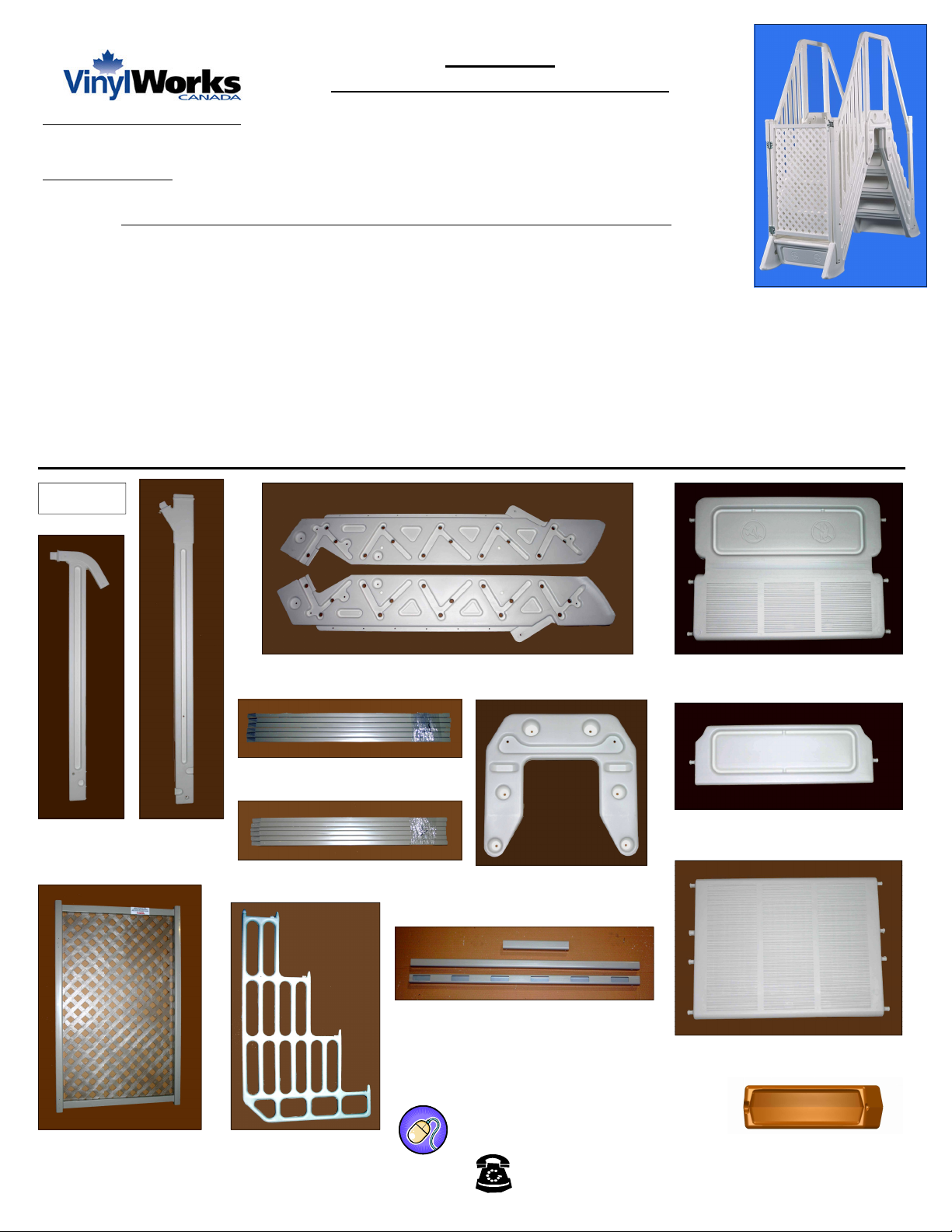
PARTS
Top Post
(4 pcs)
Bottom Post
(4 pcs)
Stair Stringers (4 pcs - 2 Left + 2 Right)
LLLL
Left Pickets (6 pcs)
RRRR
Right Pickets (6 pcs)
U-Shaped Connectors
Handrails
Top (short) - (2 pcs)
In-Pool (blank) - (2 pcs)
Exterior (with holes) - (2 pcs)
Folding Tread-Riser (8 pcs)
Bottom Riser (2 pcs)
(2 pcs)
Top Platform (1 pc)
Barrier (1 pc) Gate (1 pc)
www.vinylworkscanada.com
877-VINYL WK
Foot Extension
(4 pc)
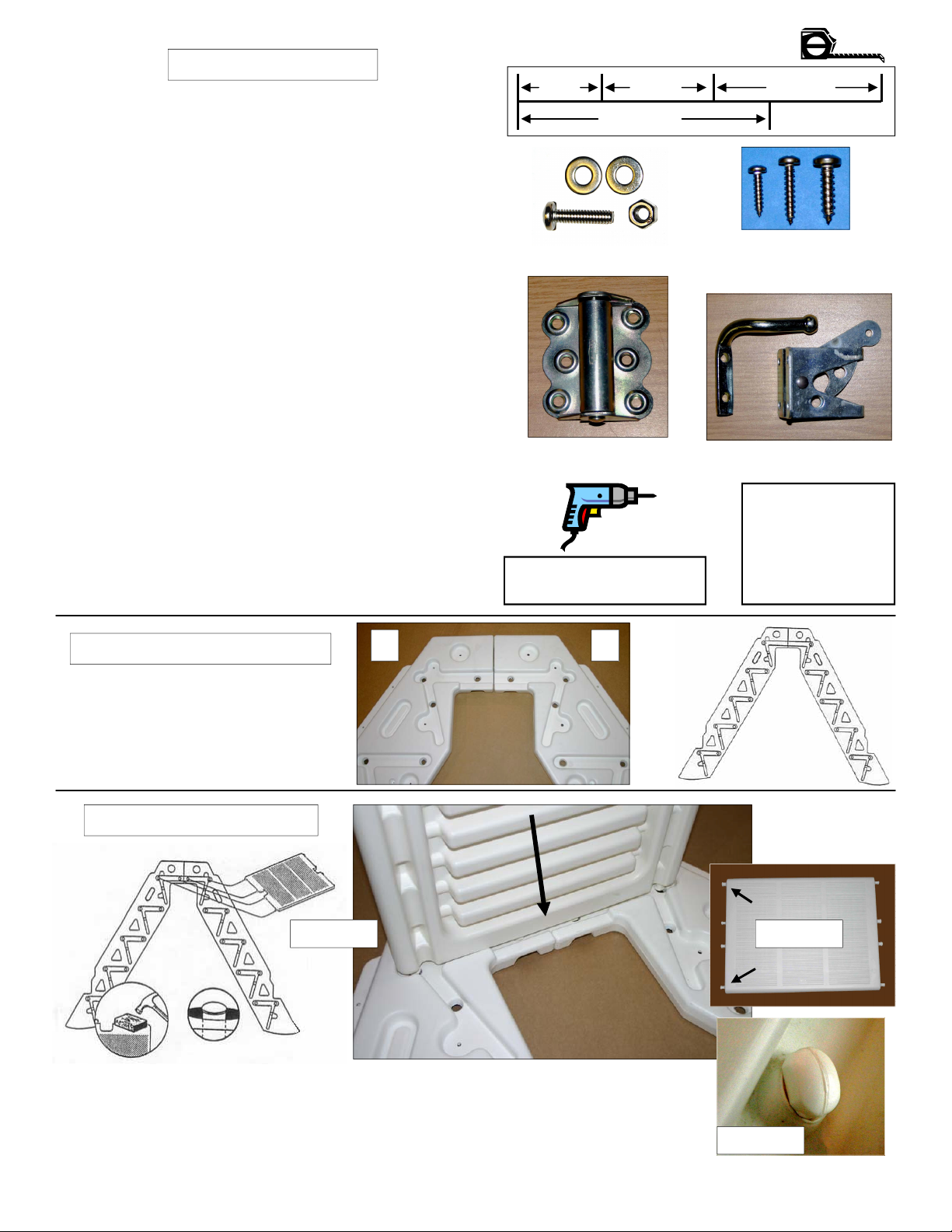
HARDWARE LIST
24 - # 8 x 3/4 inch screws
(all for handrails)
44 - # 10 x 1 inch screws
12 - for left & right pickets
18 - for spring hinges
6 - for gate latch & striker
8 - for barrier
8 - # 14 x 1 inch screws
(all for foot extensions)
12 - 3/4 inch bolts
(all for u-shaped connector)
4 - 1 inch bolts
(all for bottom post - top hole)
4 - 1-1/2 inch bolts
(all for bottom post - bottom hole)
4 - 2-1/4 inch bolts
(all for top posts)
32 - Washers
24 - for u-shaped connector (both sides)
8 - for top posts (both sides)
24 - Nuts
12 - for u-shaped connector
4 - for top posts
8 - for bottom posts
1 - Gate latch & striker
3 - Spring hinges
(one packed special with instruction)
1 - Barrier cap (on barrier for shipping)
Hardware Measurement Guide
¾"""" 1""""
1-1/2""""
2-1/4""""
Bolts (various sizes)
Spring Hinges Gate Striker & Latch
BE CAREFUL USING
TOOLS AROUND WATER
#8 #10 #14
Screws (various sizes)
READ ALL
INSTRUCTIONS
CAREFULLY
BEFORE
STARTING
ASSEMBLY
# 1 - POSITION STRINGERS
Set two stringers (Left & Right) on a
flat surface and butt at tops as
shown in Figure 1. Stringers are
marked with a “L” & “R” at the ends
to identify
L R
Figure 1
# 2 - FIT TOP PLATFORM
Figure 2.2
Fit top platform into the slots at the top of the stringers; aligning tabs / knobs on the
end of the platform (Figure 2.1) with the holes in the stringers (Figure 2.2). Make
certain the anti-skid surface of the platform is facing upward. Firmly press / tap
platform so button lock tabs of platform protrude through holes in stringers and lock
in place (Figure 2.3). Try not to damage button lock tabs at other end of top platform
Figure 2.1
Figure 2.3
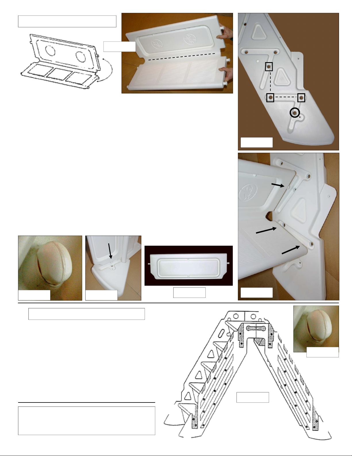
# 3 - FIT TREADS & RISERS
RRRR
Figure 3.1
TTTT
Fit folding tread-risers and bottom risers into stringers. Start by bending a
folding tread-riser down the center fold line (Figures 3.1). HINT: put treadriser in the sun to warm plastic or, if very cold out, warm fold line with hair
dryer. Do not overheat plastic as it may cause discoloration. When treadriser is folded into a “L” shape, position the end of the tread-riser, with the
locking tabs, into the groves of the stringer (see Figure 3.2 & 3.3). Proper
positioning of the folding tread-riser is outlined by the squares ( [] ) in Figure
3.2. The holes in the stringers, within the groves, accept the locking tabs on
the ends of the tread-risers. The letter “T” represents the tread portion and
the letter “R” represents the riser portion of the tread-riser part. The tread
portion has 2 locking tabs and the riser portion 1 locking tab. These fit
appropriately into the holes in the stringer outlined in Figure 3.2 & 3.3.
Firmly press / tap tread-riser so all button lock tabs protrude through holes
in stringer and lock in place (Figure 3.6). Similarly, the next tread-riser fits
directly above the part just inserted. Repeat for all 4 tread-risers on both
sides of step stringers. Fit the single bottom risers into the bottom groove
position of the stringers. Figure 3.2 outlines the single hole in the stringer
“BR” where the locking tab on the ends of the bottom riser fit ( Figures 3.2,
3.4 & 3.5). Press firmly so the button lock tab protrudes through the hole in
the stringer and locks in place (Figure 3.6). Repeat for both bottom risers
RRRR
Figure 3.2
RRRR
TTTT
BR
BR
BRBR
BR
BR
BRBR
Figure 3.5 Figure 3.6
# 4 - FIT REMAINING STRINGERS
Set remaining two stringers (L & R) on top of
installed tread-risers, top platform and bottom
risers (Figure 4.1). Stringers are in pairs - Left
(L) with Right (R) and Left with Right. Align the
button lock tabs with the holes in the two
stringers similar to Steps 2 & 3. Firmly press /
tap stringers in place with body weight or use a
small block of wood and a hammer similar to
Step 2. Make certain all tabs protrude through
the stringers and lock in place (Figure 4.2).
Leave assembled steps laying on their side
Figure 3.4
BR
BR
BRBR
TTTT
Figure 3.3
RRRR
Figure 4.2
Figure 4.1
QUESTIONS - COMMENTS - CONCERNS
CONTACT OUR CUSTOMER SERVICE FOR ASSISTANCE
877-VINYL WK
LLLL
LLLL
RRRR
 Loading...