

Page 1

Vinyl
Express Qe60
USER’S MANUAL
MANUAL NO. VEXQe06-UM-151
CUTTING PLOTTER
Signwarehouse.com
Page 2

Page 3

i
Contents
1. INTRODUCTION
1.1 Checking the Accessories ..............................................................................................1-2
1.2 Parts Names and Functions ...........................................................................................1-3
Front View ......................................................................................................................... 1-3
Rear View..........................................................................................................................1-3
Control Panel..................................................................................................................... 1-4
1.3 Assembling the Stand .....................................................................................................1-5
Stand Construction............................................................................................................1-5
Stand Assembly Instructions.............................................................................................1-5
1.4 Attaching the Basket .......................................................................................................1-7
Basket Construction .......................................................................................................... 1-7
Basket Attachment Instructions.........................................................................................1-7
2. SETTING UP THE CUTTER PLOTTER
2.1 Connecting to Your Computer .......................................................................................2-2
2.2 Turning on the Power ......................................................................................................2-3
2.3 Loading the Medium ........................................................................................................2-4
Loading a Roll Medium...................................................................................................... 2-4
Loading Sheet Media.........................................................................................................2-7
Aligning the Push Rollers .................................................................................................. 2-8
2.4 Adjusting and Mounting the Cutter Pen ......................................................................2-10
Types and Features of Cutter Blades.............................................................................. 2-10
Cutter-Pen Construction..................................................................................................2-11
Replacing the Cutter Blade..............................................................................................2-11
Adjusting the Blade Length..............................................................................................2-12
Mounting the Cutter Pen..................................................................................................2-12
3. BASIC SETTINGS AND OPERATIONS
3.1 Setting the Format of Data to be Received ...................................................................3-2
Setting the Command Mode.............................................................................................. 3-2
Setting the STEP SIZE......................................................................................................3-3
Setting the ORIGIN POINT................................................................................................3-3
3.2 Setting the Interface Conditions ....................................................................................3-4
3.3 Setting the Cutter-Pen Conditions .................................................................................3-5
Selecting Cutter-Pen-Condition Setting Areas .................................................................. 3-6
Storing Cutter-Pen-Condition Setting Areas...................................................................... 3-6
Setting TOOL (cutter blade or pen)...................................................................................3-7
Setting OFFSET................................................................................................................3-7
Setting FORCE.................................................................................................................. 3-8
Setting SPEED..................................................................................................................3-8
Setting QUALITY...............................................................................................................3-9
3.4 Displaying the Effective Cutting Area ...........................................................................3-9
3.5 Moving the Pen ................................................................................................................3-9
3.6 Setting the Initial Cutting Position ...............................................................................3-10
3.7 Stop Function ................................................................................................................3-11
3.8 Moving the Pen Carriage in +100 mm Steps ...............................................................3-12
3.9 Test Cutting ....................................................................................................................3-12
Page 4

ii
4. FUNCTION SETTINGS AND OPERATIONS
4.1 PAUSE Menu List ............................................................................................................4-2
4.2 Reading the Auto Registration Marks (Option) ............................................................4-3
4.3 Setting the FEED function ..............................................................................................4-4
4.4 Setting AUTO PRE-FEED ................................................................................................4-5
4.5 Setting TANGENTIAL Mode ............................................................................................4-6
4.6 Auto-Registration-Mark-Reading Settings (Option) .....................................................4-8
Setting the Registration-Mark Mode................................................................................4-10
4.7 Clearing the Buffer Memory .........................................................................................4-21
4.8 Aligning the Coordinate Axes ......................................................................................4-22
4.9 Distance Adjustment .....................................................................................................4-24
4.10 Setting the PAGE LENGTH ...........................................................................................4-26
4.11 Setting the Cutting/Plotting Area .................................................................................4-27
4.12 Expanding the Cutting/Plotting Area ...........................................................................4-28
4.13 Rotating the Coordinate Axes ......................................................................................4-29
4.14 Mirroring .........................................................................................................................4-30
4.15 Cutting/Plotting Using the Buffer Memory ..................................................................4-31
4.16 Sorting Settings .............................................................................................................4-33
4.17 Interface Settings ..........................................................................................................4-34
4.18 Setting the Format of Data to be Received .................................................................4-35
Setting the Command Mode............................................................................................4-35
Setting the STEP SIZE....................................................................................................4-36
Setting the ORIGIN POINT..............................................................................................4-36
4.19 Blade Wear Detection ....................................................................................................4-37
Checking the Wear Rate .................................................................................................4-37
Setting Wear-Rate Groups..............................................................................................4-38
Setting Wear-Rate Factors..............................................................................................4-39
Clearing the Total Distance (Wear Rate).........................................................................4-39
4.20 Raising and Lowering the Pen .....................................................................................4-41
4.21 TEST Mode .....................................................................................................................4-42
Condition-List Printing .....................................................................................................4-42
Dump Mode.....................................................................................................................4-43
Cutting Force Test Cutting...............................................................................................4-44
4.22 Setting the PEN UP SPEED ..........................................................................................4-46
4.23 Setting the OFFSET FORCE .........................................................................................4-47
4.24 Setting the OFFSET ANGLE .........................................................................................4-48
4.25 Setting the STEP PASS .................................................................................................4-49
4.26 Setting the Initial Down Force ......................................................................................4-50
4.27 Setting the LENGTH UNIT .............................................................................................4-51
5. Setting and Using the Special Functions
5.1 Description of Special Functions A ...............................................................................5-2
Enabling/Disabling the “:” and “;” Commands (when the COMMAND setting is GP-GL)..5-2
Moving the Pen While Raised or Lowered in Response to the “W” Command (when the
COMMAND setting is GP-GL)........................................................................................... 5-2
Model ID Response (when the COMMAND setting is HP-GL)..........................................5-2
SETTING PRIORITY.........................................................................................................5-2
Blade-Tip Initial Position Setting........................................................................................5-2
Enabling/Disabling PEN UP MOVE...................................................................................5-3
Enabling/Disabling the Media Sensors..............................................................................5-3
Page 5

iii
Enabling/Disabling the Home Sensors..............................................................................5-3
Setting the PARALLEL I/F Mode.......................................................................................5-3
Circle-Command Resolution Setting (when the COMMAND setting is HP-GL)................5-3
Enabling/Disabling Blade Wear Detection......................................................................... 5-3
5.2 Setting Special Functions A ...........................................................................................5-4
5.3 Description of Special Functions B ...............................................................................5-4
Display Language Setting (MENU LANGUAGE SELECTION).........................................5-4
5.4 Setting Special Functions B ...........................................................................................5-5
6. TROUBLESHOOTING
6.1 The Cutting Plotter Does Not Operate When Turned On .............................................6-2
6.2 The Cutting Plotter Does Not Operate Correctly ..........................................................6-2
6.3 The Cutting Results Are Unsatisfactory ........................................................................6-3
6.4 An Error Message Was Displayed .................................................................................6-4
APPENDIX
Appendix A Main Specifications .........................................................................................................A-2
Appendix B Options and Supplies ......................................................................................................A-3
Appendix C External Dimensions .......................................................................................................A-4
Appendix D Menu Tree .........................................................................................................................A-5
INDEX
Page 6

iv
Page 7

1
1
INTRODUCTION
1.1 Checking the Accessories
......................................................1-2
1.2 Parts Names and Functions
...................................................1-3
1.3 Assembling the Stand
...............................................................1-5
1.4 Attaching the Basket
.................................................................1-7
Page 8
1 – 2
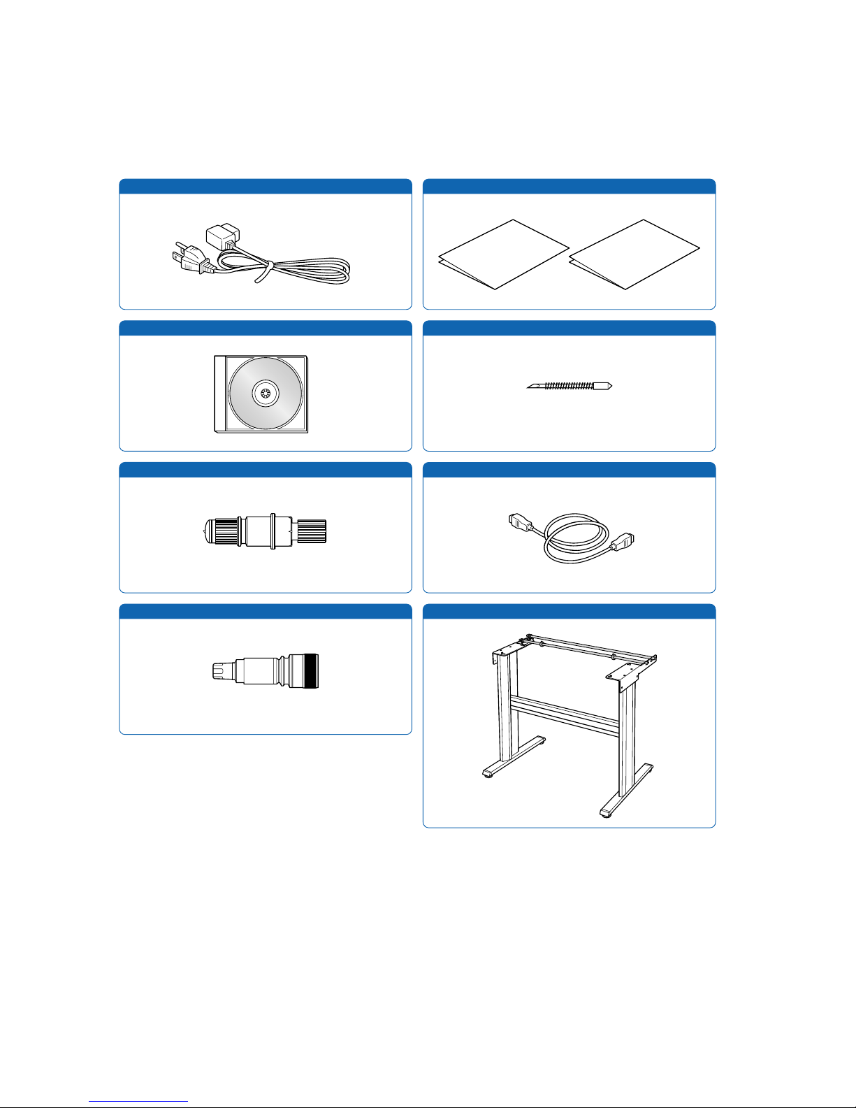
1.1 Checking the Accessories
Check to confirm that all of the standard accessories listed below are present. If any item is missing,
please contact your sales representative or nearest Signwarehouse vendor promptly.
AC power cord Quick Start Manual, Usage Precautions
User Guide CD-ROM
Stand
Cutter blade (CB09UA)
Water-based fiber-tip pen
1 1 each
1
1
1
1
Cutter plunger
1
USB cable
1
Page 9

1 – 3
1.2 Parts Names and Functions
■
Front View
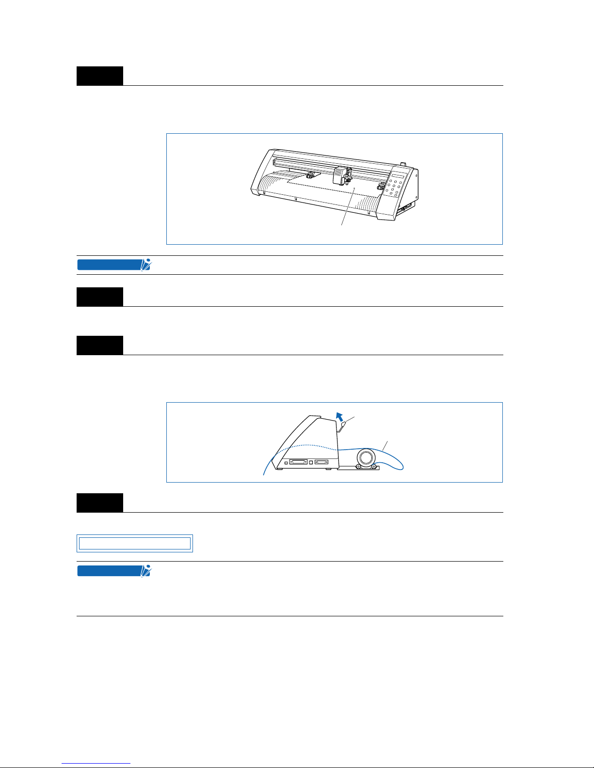
Cutting mat
: Cutting or plotting is performed on this mat.
Grit roller
: Feeds the medium backward or forward
Push rollers
: Pushes the medium against the grit rollers
Pen carriage
: Moves the cutter pen to the left and right
Pen holder
: Holds the cutter pen and moves it up and down
Media set lever
: Raises or lowers the push rollers during loading of a medium
Control panel
: Used to operate the cutting plotter and set functions
Parallel (Centronics) interface connector : Used to connect a Centronics-compatible parallel interface cable
USB interface connector
: Used to connect a USB cable
Serial (RS-232C) interface connector
: Used to connect an RS-232C serial interface cable
■
Rear View
AC power inlet
: Connects the power cord to the cutting plotter
Power switch
: Turns the power supply to the cutting plotter on or off
Cutting mat
Grit roller
Pen carriage
Push rollers
Media set leverPen holder
USB interface
connector
Serial (RS-232C)
interface connector
Control panel
Parallel (Centronics)
interface connector
AC power inlet
Power switch
Page 10
1 – 4
■
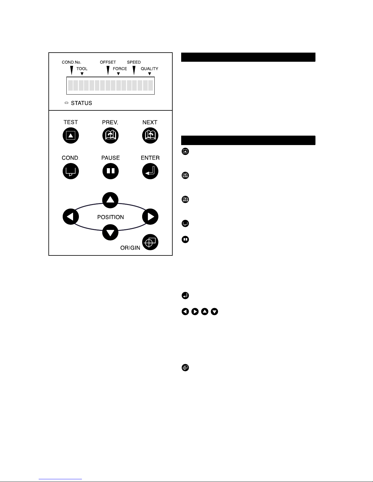
Control Panel
STATUS: Illuminates while the power to the cut-
ting plotter is turned on, and goes out
when the cutting plotter is in PAUSE
status. This lamp flashes when data is
being received from an interface,
regardless of whether or not the cutting
plotter is in PAUSE status.
TEST: Press this function key to conduct a cut-
ting test and check the cutting conditions.
PREV.: Press this function key to view the pre vi-
ous display on the LCD when in PAUSE
status.
NEXT: Press this function key to view the next
display on the LCD when in PAUSE status.
COND.: Press this function key to view the cut-
ter-pen condition settings.
PAUSE: Press this function key once in READY
status to switch to PAUSE status in
order to change the various settings.
Press it again to cancel the PAUSE status. Pressing this key while cutting or
plotting is in progress stops the cutting
or plotting.
ENTER: Pressing this function key registers the
cutting or plotting conditions set.
POSITION:
These keys are used to mov e the cursor
or change the settings on the LCD display on the function setting screens.
Press these keys when in PAUSE status
to move the pen carriage or the
medium.
ORIGIN: Press this function key to set the origin
point. The pen position is set as the origin point when this key is pressed.
Indicator Lamp
Panel Keys
Page 11

1 – 5
1.3 Assembling the Stand
■ Stand Construction
The stand is made up of the following parts.
■ Stand Assembly Instructions
Fasten the stand feet (L/R) to the stand side bars (L/R) with the hexagonal socket bolts (M5), using the
Allen wrench.
Fasten the stand tops (L/R) to the stand side bars (L/R) with the hexagonal socket bolts (M5), using the
Allen wrench.
Step
1
Step
2
Stand feet (L/R)
Hexagonal socket bolt
(M5) x 12
Coin screw x 4
Allen wrench (M5)
Center barStand side bars (L/R)
Hexagonal
socket bolt (M5)
Stand side bar
Stand foot
Front
* There are three
bolt holes, but
the center one
is not used.
Hexagonal
socket bolt (M5)
Stand side bar
Stand top
Page 12
1 – 6
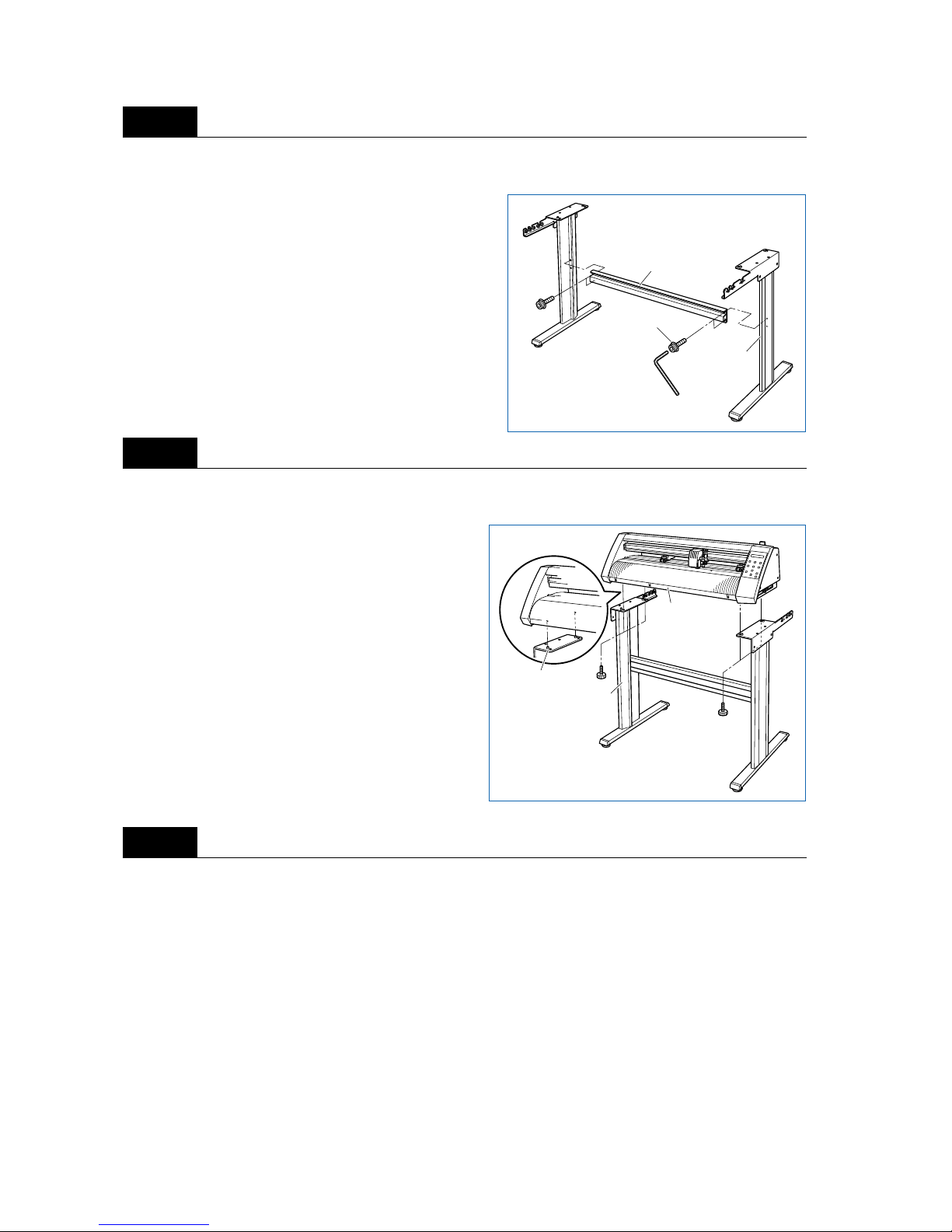
Loosely fasten the stand side bars (L/R) to the center bar with the hexagonal socket bolts (M5), using the
Allen wrench.
Mount the Vinyl Express cutting plotter on the stand by inserting the positioning pins on the stand into the
positioning holes on the underside of the cutting plotter. Fasten using the four coin screws.
Tighten the hexagonal socket bolts loosely fastened in step 3.
Step
3
Step
4
Step
5
Hexagonal
socket bolt (M5)
Center bar
Stand side bar
Coin screws
Stand
cutting plotter
Positioning pins
Page 13
1 – 7
1.4 Attaching the Basket (Optional)
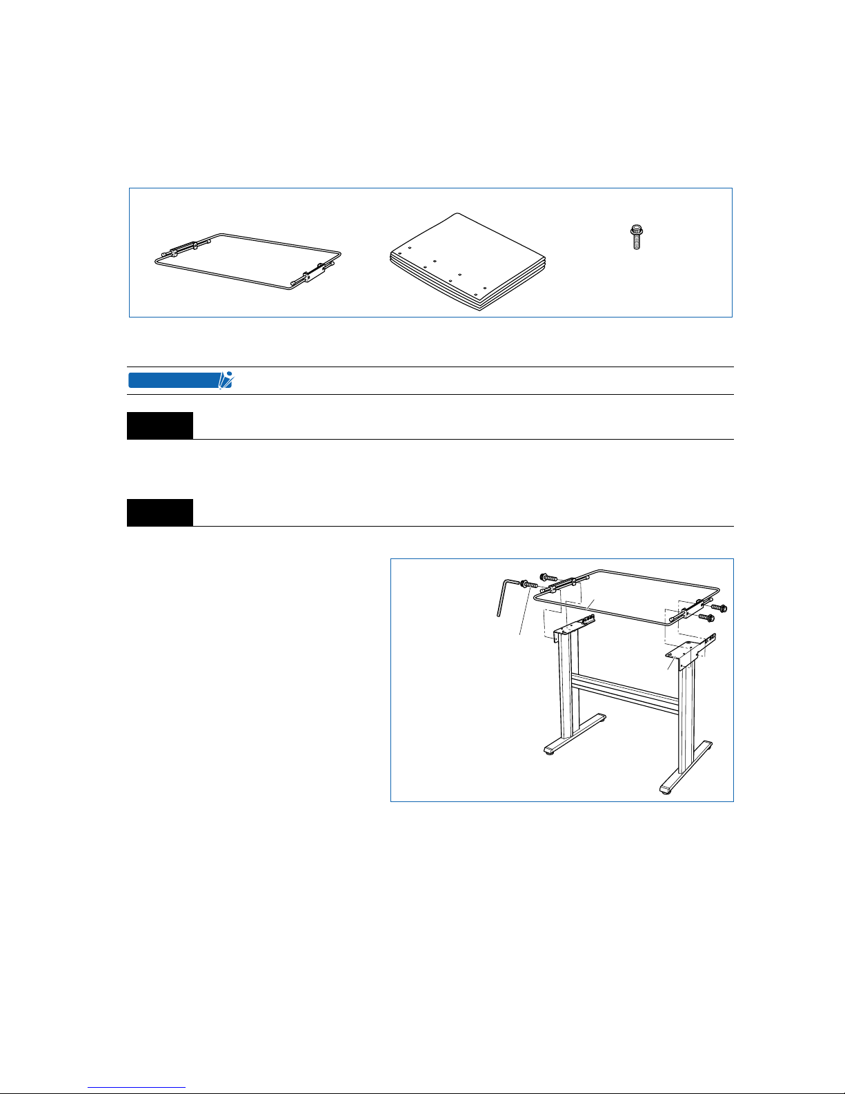
■ Basket Construction
The basket is made up of the following parts.
■ Basket Attachment Instructions
Detach the four coin screws or he xagonal soc k et bolts (M6), and separate the cutting plotter from the stand
(see “1.3 Assembling the Stand”).
Attach the sheet support pipe to the stand tops, and fasten using the hexagonal socket bolts.
At least two people are required for assembly of the basket.
Step
1
Step
2
Sheet support pipe Sheet Hexagonal socket bolts (M6) x 4
CHECKPOINT
Sheet support pipe
Stand top
Hexagonal socket bolts (M6)
Page 14
1 – 8
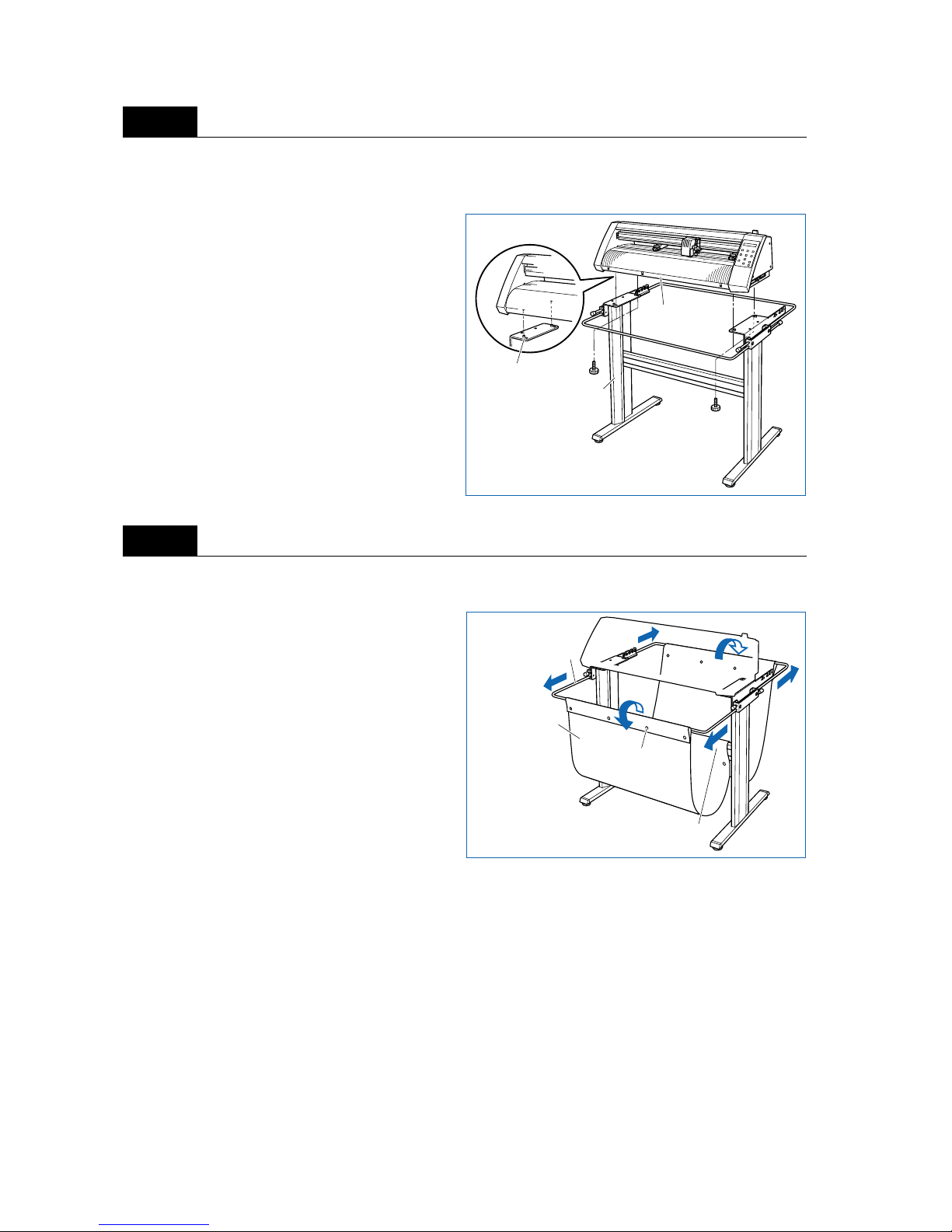
Mount the Vinyl Express cutting plotter on the stand by inserting the positioning pins on the stand into the
positioning holes on the underside of the cutting plotter. Fasten using the four coin screws or hexagonal
socket bolts (M6).
Pull out the sheet support pipe and attach the sheet. Divide the sheet over the center bar, and then fasten
the sheet to the sheet support pipe using the press-studs.
Step
3
Step
4
Coin screws
Stand
cutting plotter
Positioning pins
Sheet
Press-studs
Sheet support pipe
Divide over
the center bar
Page 15

2
2
SETTING UP THE CUTTER PLOTTER
2.1 Connecting to Your Computer................................................2-2
2.2 Turning on the Power................................................................2-3
2.3 Loading the Medium..................................................................2-4
2.4 Adjusting and Mounting the Cutter Pen...........................2-10
Page 16
2 – 2
2.1 Connecting to Your Computer
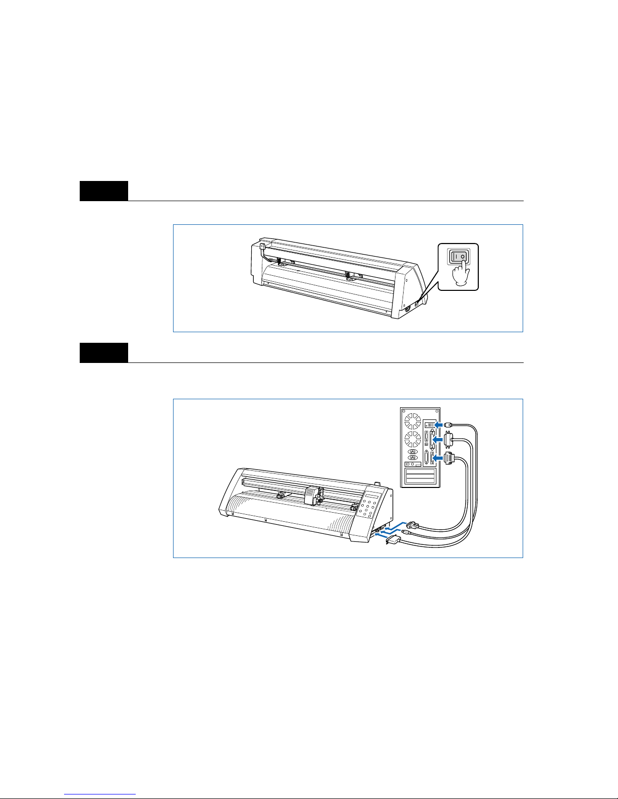
The cutting plotter can be connected to a computer via the parallel (Centronics-compatible) port, serial
(RS-232C) port, or USB por t. Select which port to use according to the requirements of your application
software and/or which of your computer’s interface ports are available for use.
Use a Centronics-compatible parallel cable, serial cable, or USB cable in accordance with the connection
method chosen. Obtain a Signwarehouse approved interface cable that is compatible with the interface
ports (the interface cables are available separately).
Check to confirm that the Power switch is turned off (the “O” side is down).
Connect the cable between the cutting plotter and the computer. Make sure the connectors at the cutting
plotter and computer ends are correctly oriented.
Step
1
Step
2
Page 17
2 – 3
2.2 Turning on the Power
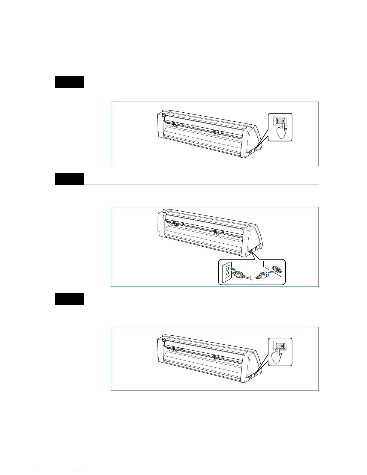
Connect the cutting plotter to the AC electrical socket using the power cord provided, and turn on the
power.
Check to confirm that the Power switch is turned off (the “O” side is down).
Connect the cutting-plotter AC power inlet to a correctly rated electrical socket using the power cord provided.
Turn on the cutting plotter by pressing the “|” side of the Power switch. The STATUS lamp on the control
panel will light up.
Step
1
Step
2
Step
3
Page 18
2 – 4
If no medium has been loaded, the message below appears on the display, prompting the loading of a
medium.
If a medium has already been loaded, the current media setting is displayed as shown below.
Select the media mode to suit the medium used. F or instructions on loading media and selecting the media
mode, see “2.3 Loading the Medium.”
2.3 Loading the Medium
Load the medium, aligning it with the right-hand grit roller when viewed from the front so that it registers
with the media sensor. Then, adjust the push-roller position to match the width of the medium. The cutting
plotter can use media in roll or sheet form. Load the desired medium type by following the appropriate
instructions.
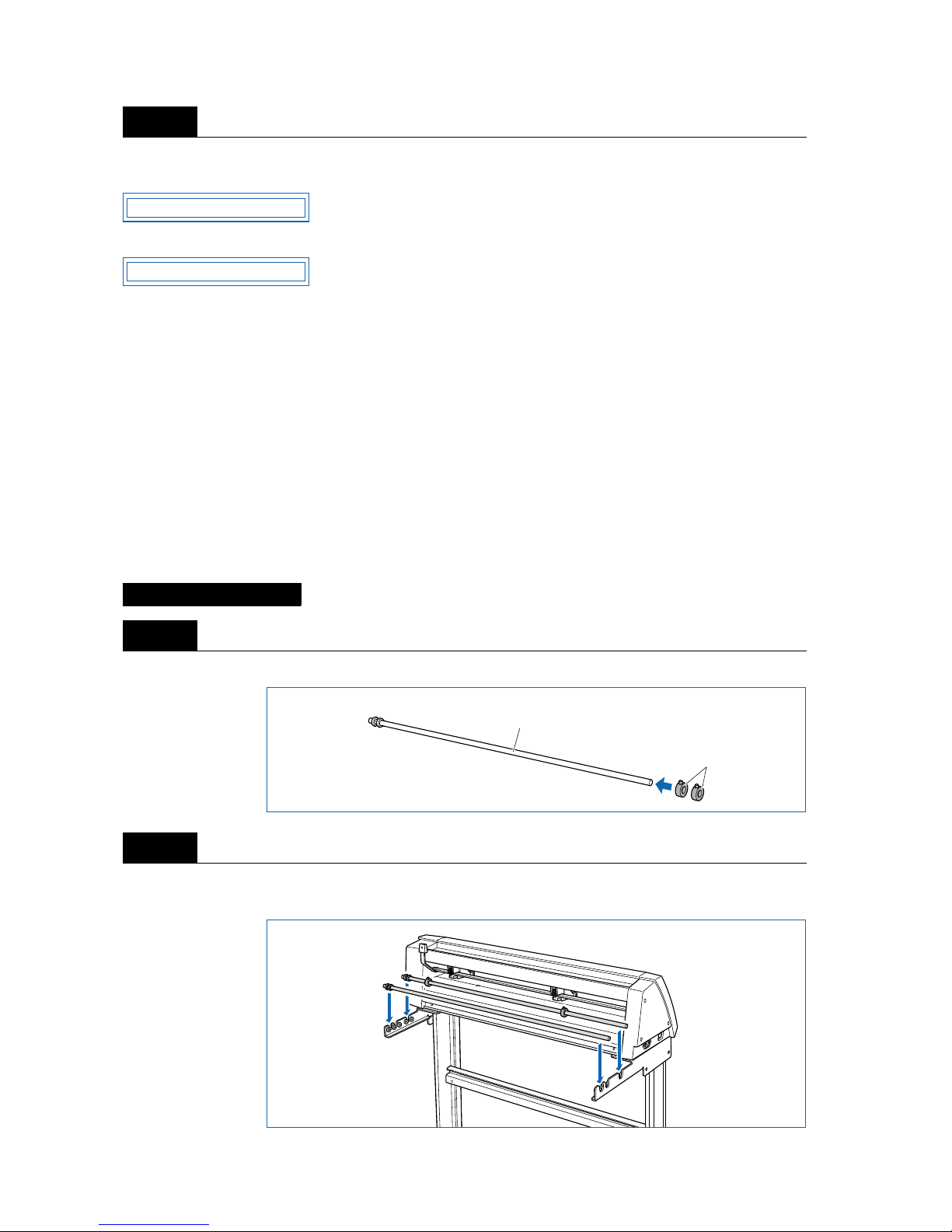
■ Loading a Roll Medium
Load the roll medium onto the stand stock rollers.
Fit the stoppers to one of the stock rollers (loosen the screws on the stoppers first).
Position the stock roller with the stoppers towards the front, and place the other stock roller toward the rear
to suit the roll-medium size.
Step
4
Placing on the Stand
Step
1
Step
2
LOAD MEDIA!!
ROLL2 PRESS ENTR
Stoppers
Stock roller
Page 19

2 – 5
Place the roll medium on the stock rollers, and clamp it between the stoppers. Once the position is fixed,
tighten the screws on the stoppers.
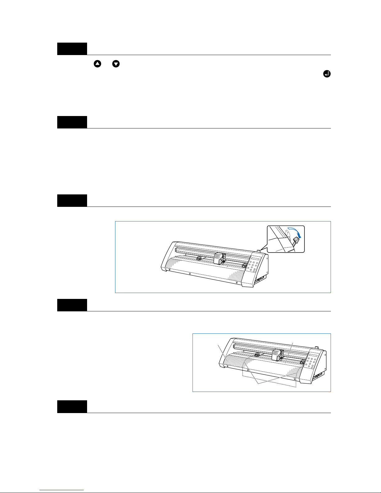
Lower the media set lever to raise the push rollers.
Place the roll medium on the stand stock rollers, and then pass the leading edge of the medium from the
back of the cutting plotter so it emerges from the front, while making sure to remove any slack in the
medium conveyance path.
Step
3
Loading the Roll Medium
Step
1
Step
2
Page 20
2 – 6
Pull the leading edge out of the front of the cutting plotter so that it completely covers the media sensor. If
the leading edge has been pulled out too far , turn the roll to adjust the length of the medium that is protruding.
Adjust the position of the left- and right-hand push rollers to suit the width of the roll medium.
After ensuring that there is no slack in the medium’s conveyance path, raise the media set lever to lower
the push rollers and provide slack in the medium for a length corresponding to the length of the medium to
be used.
Raising the media set lever displays a menu for selection of the media mode. Select the media mode.
Step
3
Load the medium so that it passes over the media sensor.
Step
4
Step
5
Step
6
If the “REALIGN ROLLERS” message is displayed when the medium is loaded
and the media set lever is raised, either the right-hand push roller is not positioned
over the right-hand wide grit roller or the left-hand push roller is not positioned over
the grit roller. Check to confirm that they are positioned correctly.
Media sensor
CHECKPOINT
Raise media set lever to
clamp medium
Provide slack
ROLL2 PRESS ENTR
CHECKPOINT
Page 21
2 – 7
Pressing the or key displays “ROLL1 PRESS ENTR”, “ROLL2 PRESS ENTR”, and “SHEET
PRESS ENTR”. Select “ROLL2 PRESS ENTR” or “ROLL1 PRESS ENTR” and then press the
(ENTER) key to confirm. When “ROLL2 PRESS ENTR” is selected, only the medium width is detected.
Select this mode to begin cutting at a point beyond the leading edge. When “ROLL1 PRESS ENTR” is
selected, the leading edge and width of the medium are detected. Select this mode to begin cutting from
the leading edge.
After the medium size has been detected, the pen carriage returns to the origin point and the cutting plotter
awaits cutting data. If the INTERFACE conditions or COMMAND mode have not yet been set, they should
be set. If they have already been set, adjust the cutter pen. Once the cutter pen has been adjusted, the
cutting plotter is ready to perform cutting, so cutting data can be sent from the application software on the
computer.
■ Loading Sheet Media
Lower the media set lever to raise the push rollers.
With the Vinyl Express, position the edges of the medium flush against the guide lines engraved on the
front guide.
Adjust the position of the left- and right-hand push rollers to suit the medium width.
Step
7
Step
8
Step
1
Step
2
Step
3
Guide lines
Media sensor
Flush
Page 22
2 – 8
Raising the media set lever displays a menu for selecting the media mode. Select the media mode.
Pressing the or key displays “ROLL1 PRESS ENTR”, “ROLL2 PRESS ENTR”, and “SHEET
PRESS ENTR”. Select “SHEET PRESS ENTR” and then press the (ENTER) key to confirm the
selection. When “SHEET PRESS ENTR” is selected, the front and rear edges are detected.
After the medium size has been detected, the pen carriage returns to the origin point and the cutting plotter
awaits cutting data. If the INTERFACE conditions or COMMAND mode have not yet been set, they should
be set. If they have already been set, adjust the cutter pen. Once the cutter pen has been adjusted, the
cutting plotter is ready to perform cutting, so cutting data can be sent from the application software on the
computer.
■ Aligning the Push Rollers
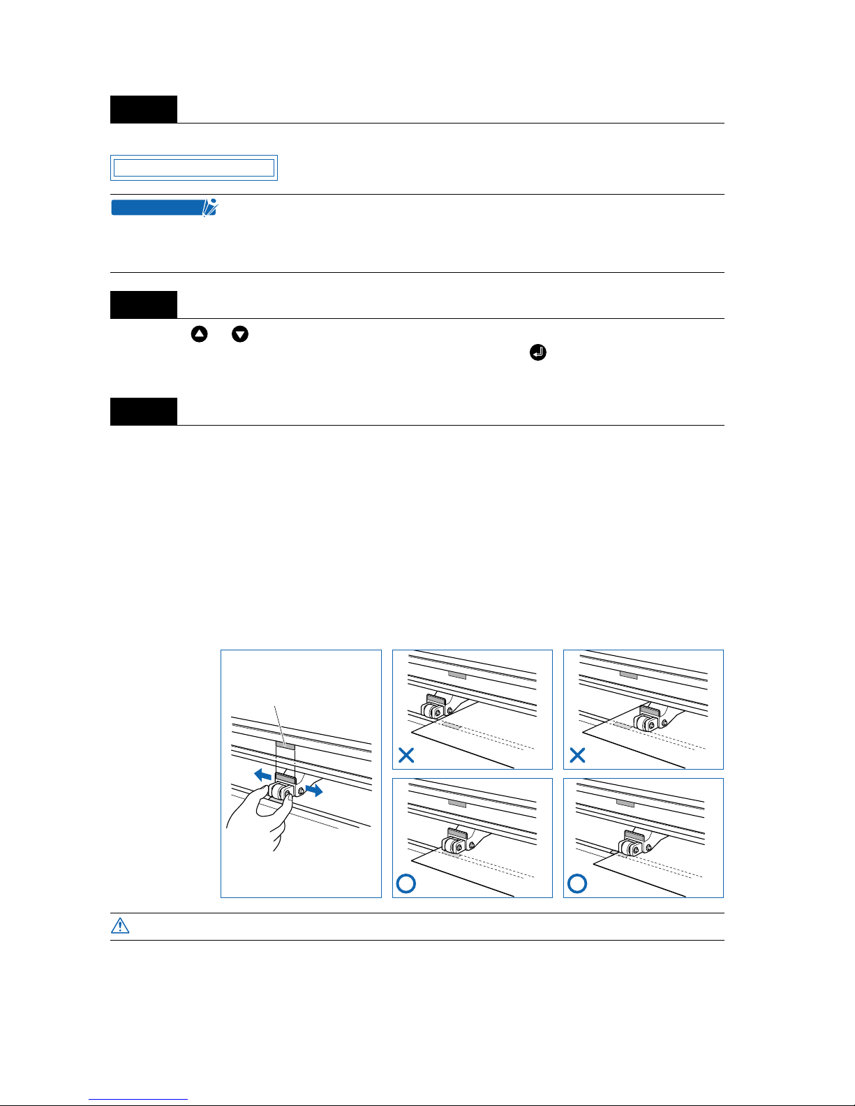
Adjust the position of the left- and right-hand push rollers to suit the medium width. Position the push rollers at either edge of the medium so that they are above the grit rollers. Adjust the push rollers so that they
are positioned above both the medium and the grit rollers. Positioning the push rollers within the pushroller alignment marks ensures that they are above the grit rollers.
Step
4
If the “REALIGN ROLLERS” message is displayed when the medium is loaded
and the media set lever is raised, either the right-hand push roller is not positioned
over the right-hand wide grit roller, or the left-hand push rollers are not positioned
over the grit roller. Check to confirm that they are positioned correctly.
Step
5
Step
6
To move the push rollers, the media set lever must be in the lowered position.
SHEET PRESS ENTR
CHECKPOINT
Push-roller alignment mark
NG NG
OK OK
CAUTION
Page 23
2 – 9
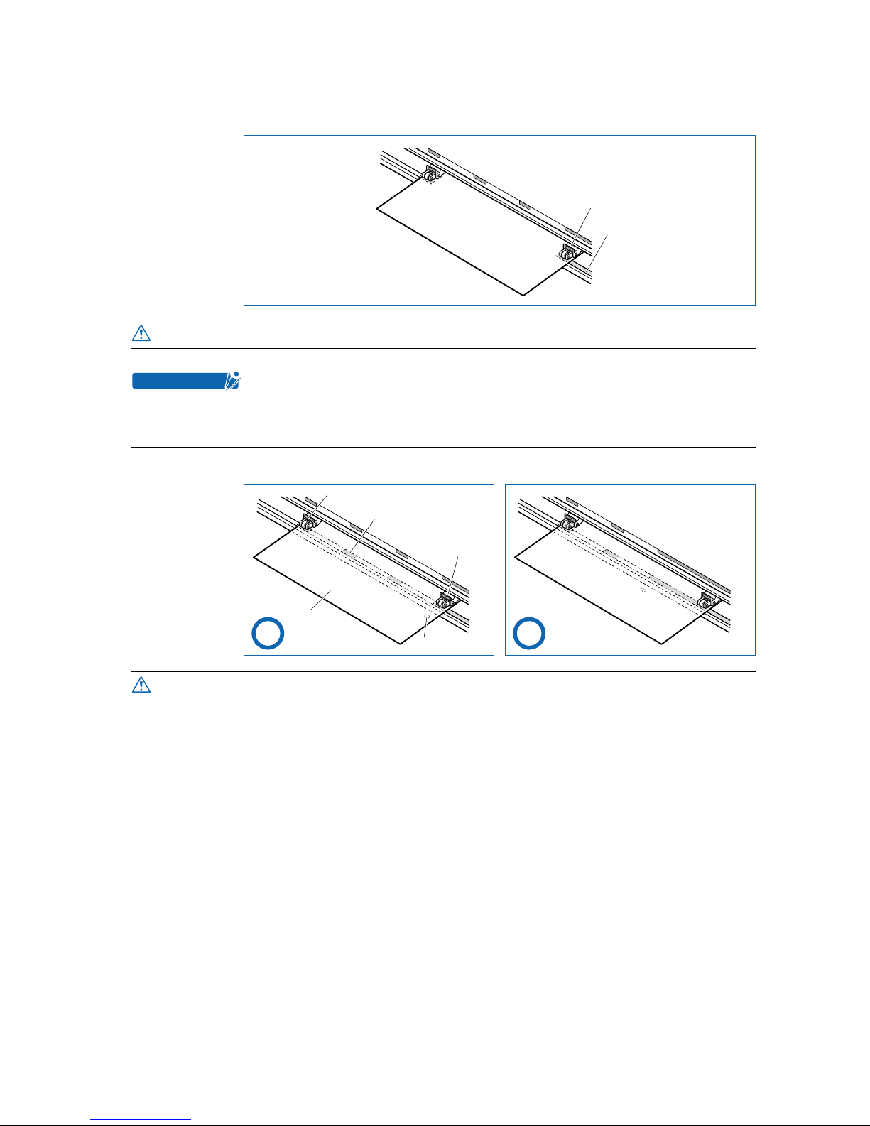
The push roller on the right-hand edge when viewed from the front must always be moved over the righthand wide grit roller.
Position the push rollers over the grit rollers to grip each edge of the medium.
To move the push rollers, the media set lever must be in the lowered position.
If the “REALIGN ROLLERS” message is displayed when the medium is loaded
and the media set lever is raised, either the right-hand push roller is not positioned
over the right-hand wide grit roller, or the left-hand push roller is not positioned
over the grit roller. Check to confirm that they are positioned correctly.
• The push roller (1) must be positioned over the right-hand wide grit roller.
• The medium must always be positioned over the media sensor.
Right-hand push roller
Right-hand grit roller
CAUTION
CHECKPOINT
Media sensor
Push roller (1)
Push roller (2)
Grit roller
Medium
OK OK
CAUTION
Page 24
2 – 10
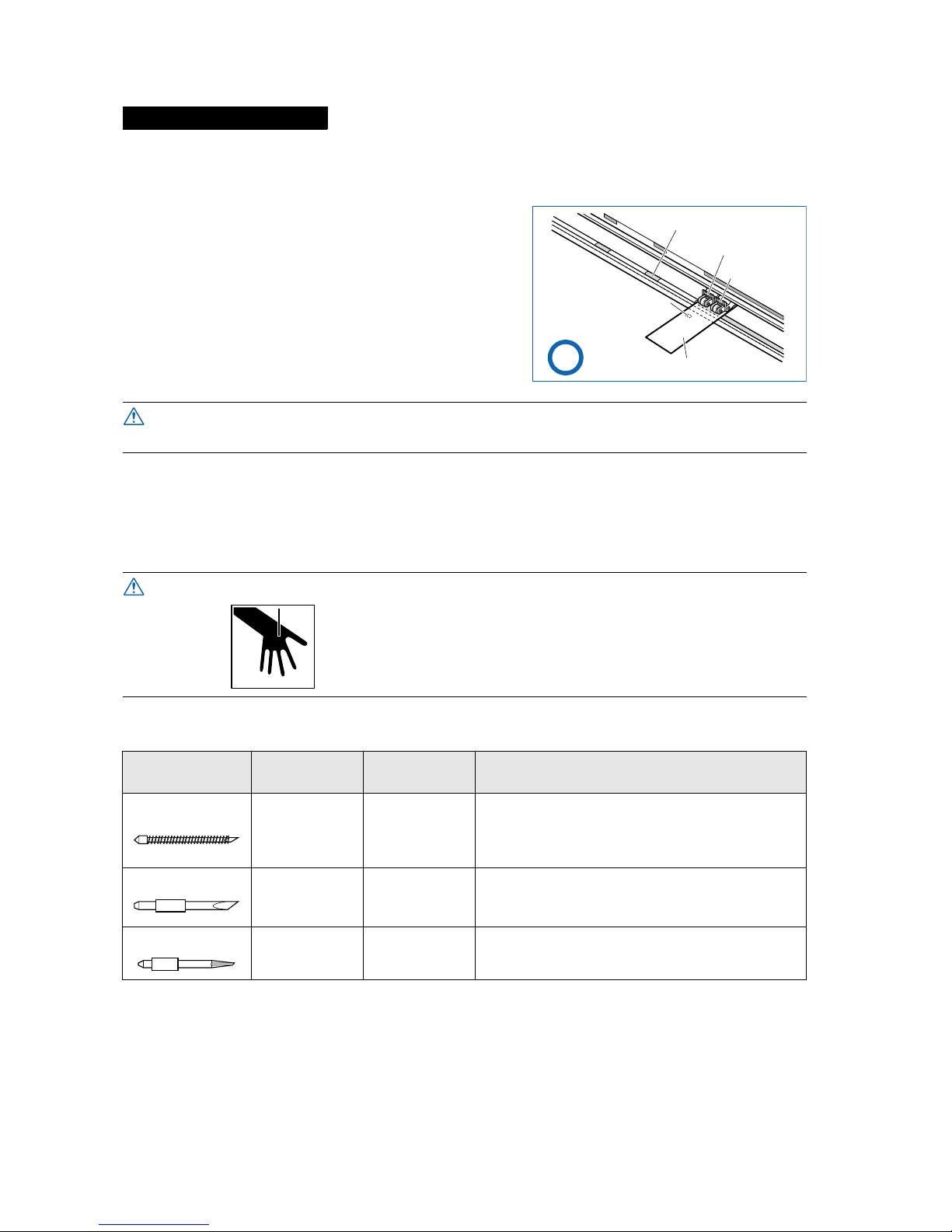
Position all of the rollers over the r ight-hand wide grit roller. Position the medium with the left-hand edge
aligned with the left-hand edge of the grit roller, and position the push rollers over both edges. The minimum width of the medium that can be set is 50 mm for the Vinyl Express.
2.4 Adjusting and Mounting the Cutter Pen
Individual cutter blades have a var iety of features. Select the optimal cutter blade to suit the medium to be
cut.
■ Types and Features of Cutter Blades
For Minimum-Size Media
• The medium must be at least 125 mm in length.
• The medium must always be positioned over the media sensor.
To avoid cutting your fingers, always handle the cutter blade with caution.
Part No. and
profile
Blade diameter
and offset
Compatible
plunger
Use and features
CB 09UA ø0.9 mm
0.45
PHP32-CB09N The standard blade for cutting color adhesive-backed
media. Suitable for cutting media up to 0.25 mm in
thickness.
Max. cutting distance: Approx. 4,000 m
CB 15U ø1.5 mm
0.75
PHP32-CB15N Capable of cutting thicker media than possible with the
CB09UA blade. Suitable for cutting media 0.25 mm to
0.5 mm in thickness.
CB 15UB ø1.5 mm
0.15
PHP32-CB15N Suitable for detailed cutting (e.g., letters less than 10
mm in size) of media up to 0.25 mm in thickness.
Medium
Push roller (2)
Grit roller
Media sensor
Push roller (1)
OK
CAUTION
CAUTION
Page 25
2 – 11
■ Cutter-Pen Construction
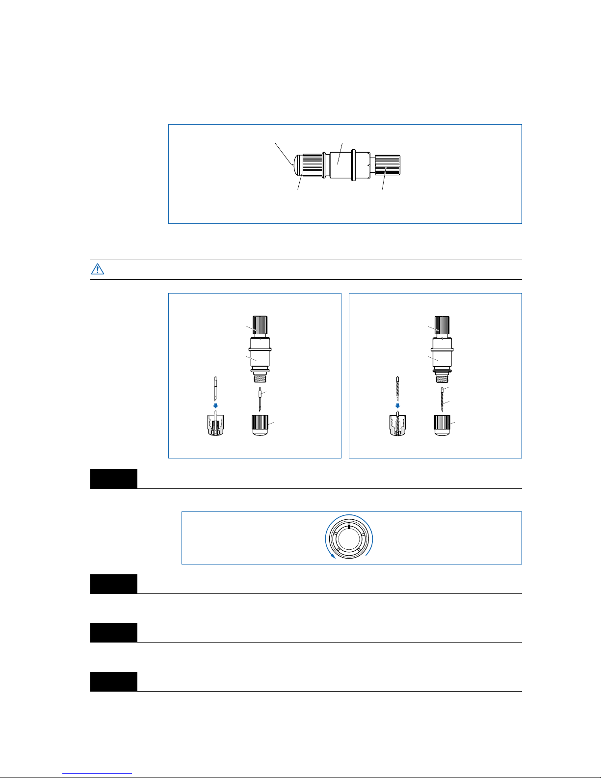
The cutting plotter cuts using a cutter blade mounted in a cutter-pen plunger. There are two different cutterpen plungers to suit the diameter of the cutter blade to be mounted (the 0.9-mm cutter-pen plunger is provided as standard equipment). Be sure to mount the cutter blade in the corresponding cutter-pen plunger.
■ Replacing the Cutter Blade
Turn the blade-length adjustment knob to retract the blade into the plunger.
Turn the plunger cap in the counter-clockwise direction to remove it from the plunger.
Remove the blade from inside the plunger cap.
Insert the new blade into the hole provided in the plunger cap.
To prevent cutting your fingers, always handle the cutter blade with caution.
Step
1
Step
2
Step
3
Step
4
Cutter blade
Plunger cap
Plunger
Blade-length adjustment knob
(Blue: For 0.9-mm-diameter blades)
(Red: For 1.5-mm-diameter blades)
CAUTION
1.5-mm-diameter cutter pen
Plunger-cap
cross-section
Plunger cap
1.5-mm-dia. blades
Blade-length
adjustment knob (red)
Plunger
Spring
Plunger cap
Plunger-cap
cross-section
0.9-mm-dia. blades
0.9-mm-diameter cutter pen
Blade-length
adjustment knob (blue)
Plunger
Page 26
2 – 12
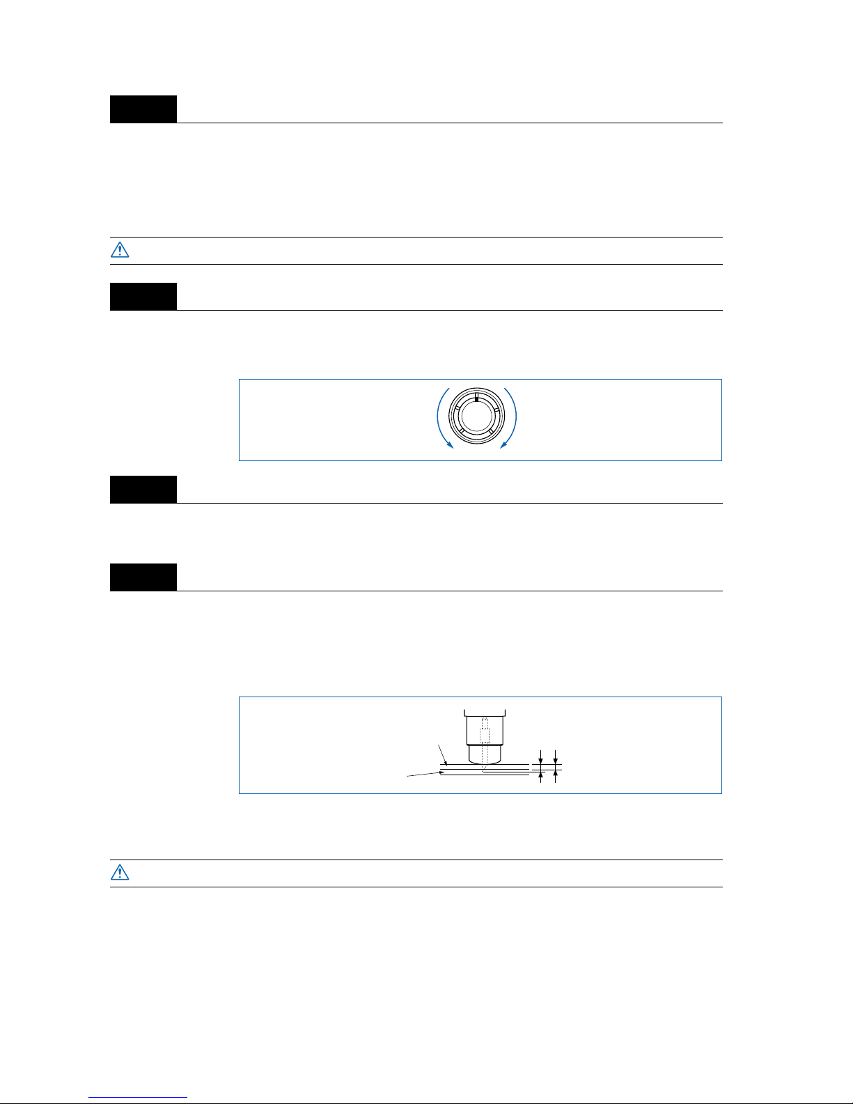
With the blade inserted into the plunger cap, screw on the plunger from above.
■ Adjusting the Blade Length
If the blade is extended too far in relation to the thickness of the medium being cut, it will damage the cutting mat. Be sure to adjust the blade length correctly.
Adjust the blade length by turning the blade-length adjustment knob. Turn the knob in direction “A” to
extend the blade, or in direction “B” to retract the blade. When the knob is turned by one scale unit, the
blade moves approximately 0.1 mm. One full turn of the knob moves the blade approximately 0.5 mm.
First align the blade tip with the tip of the cutter pen, and then extend the blade from that position to suit the
thickness of the media to be cut.
Assuming that the medium thickness is “t,” as shown in the figure below, the blade length “rrrr” should be
equal to or slightly greater than “t.” Make sure “rrrr” is never greater than the combined thickness of the
medium and its backing sheet. If it is not possib le to accurately determine the medium thickness , adjust the
blade length by gradually increasing it until only traces of the b lade appear on the bac king sheet after a cutting test is conducted.
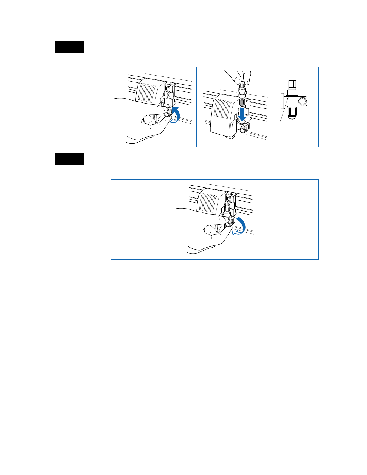
■ Mounting the Cutter Pen
After the blade length has been adjusted, mount the cutter pen in the cutting plotter.
Step
5
To prevent cutting your fingers, always handle the cutter blade with caution.
Step
1
Step
2
Step
3
To prevent cutting your fingers, always handle the cutter blade with caution.
CAUTION
AB
t
Medium
Backing sheet
R
CAUTION
Page 27
2 – 13
Loosen the pen-holder screw and then mount the cutter pen.
Once the cutter pen is properly positioned, tighten the pen-holder screw.
Step
1
Step
2
Press the plunger in
firmly so that it
contacts this surface
of the pen holder.
Page 28

2 – 14
Page 29

3
3
BASIC SETTINGS AND OPERATIONS
3.1 Setting the Format of Data to be Received .......................3-2
3.2 Setting the Interface Conditions...........................................3-4
3.3 Setting the Cutter-Pen Conditions.......................................3-5
3.4 Displaying the Effective Cutting Area.................................3-9
3.5 Moving the Pen............................................................................3-9
3.6 Setting the Initial Cutting Position (Origin Point) ...........3-10
3.7 Stop Function ............................................................................3-11
3.8 Moving the Pen Carriage in +100 mm Steps...................3-12
3.9 Test Cutting ................................................................................3-12
Page 30

3 – 2
3.1 Setting the Format of Data to be Received
Before data is sent from the computer , the f ormat (command mode) of the data sent by the application software must be checked. The cutting plotter accepts two data formats (command modes): GP-GL (Gr aphtec)
and HP-GL commands. Set the command mode to suit the application used.
■ Setting the Command Mode
Check to confirm that the cutting plotter is in READY mode (displaying the current pen settings).
Press the (PAUSE) key to switch to PAUSE mode, and then press the (NEXT) or (PREV.) key
until the menu shown below is displayed.
Press the (ENTER) key to display the menu shown below.
Press the or key to select “GP-GL” or “HP-GL,” and then press the (ENTER) key to confirm.
To cancel the selection, press the (NEXT) or (PREV.) key.
If “GP-GL” is selected, set the STEP SIZE. If “HP-GL” is selected, set the ORIGIN POINT. If a different
command from that set previously is selected, the PAUSE mode is automatically cancelled once the STEP
SIZE (GP-GL) or ORIGIN POINT (HP-GL) is set.
Step
1
Step
2
Step
3
Step
4
Step
5
1 PEN 23 30 2
COMMAND
COMMAND HP-GL
Page 31

3 – 3
■ Setting the STEP SIZE
If the GP-GL command mode is set, it is possible to change the minimum unit of distance that the cutter
pen or pen can travel to one of four settings: 0.01 mm, 0.025 mm, 0.05 mm, or 0.1 mm. The default setting
is 0.1 mm, so this setting should be changed if your application specifies a different step size.
Set the command setting to “GP-GL.”
Press the (ENTER) key to display the step-size setting.
Press the or key to select “0.100 mm,” “0.050 mm,” “0.025 mm,” or “0.010 mm,” and then press
the (ENTER) key to confirm. To cancel the selection, press the (NEXT) or (PREV.) key.
Press the (PAUSE) key to cancel PAUSE mode.
■ Setting the ORIGIN POINT
If the HP-GL command mode is set, the origin point can be set to the lower left or center. The default setting is the lower left, so this setting should be changed if your application specifies a different origin position.
Set the command setting to “HP-GL.”
Press the (ENTER) key to display the origin-point setting.
Press the or key to select “L.L. (LOWER LEFT)” or “CENTER,” and then press the (ENTER)
key to confirm. To cancel the selection, press the (NEXT) or (PREV.) key.
Press the (PAUSE) key to cancel PAUSE mode.
Step
1
Step
2
Step
3
Step
4
Step
1
Step
2
Step
3
Step
4
COMMAND GP-GL
STEP SIZE 0.100mm
COMMAND HP-GL
ORIGIN PT L.L.
Page 32

3 – 4
3.2 Setting the Interface Conditions
The interface conditions must be set if the RS-232C serial interface is being used. The data transfer rate
(baud rate), data length, parity settings, and the handshaking mode for the cutting plotter must be set to
match those of the computer operating system. This section describes the cutting-plotter interface conditions. For details on the proper settings for your application or computer operation system, refer to the
manual provided with the application or operating system.
Check to confirm that the cutting plotter is in READY mode (displaying the current pen settings).
Press the (PAUSE) key to switch to PAUSE mode, and then press the (NEXT) or (PREV.) key
until the menu shown below is displayed.
Press the (ENTER) key to display the interface settings.
The current settings are displayed (from the left): transfer rate (baud rate), parity, data length, and handshaking mode.
The baud rate can be set to “19200,” “9600,” “4800,” “2400,” “1200,” “600,” or “300.”
The parity can be set to “N” (None), “E” (Even parity), or “O” (Odd parity). The data length can be set to 7
or 8 bits.
The handshaking mode can be set to “H” (hard-wired handshaking) or “X” (Xon/Xoff handshaking). “E”
(ENQ/ACK handshaking) can also be selected when the command mode is set to HP-GL.
All of these interface conditions must be set to match the corresponding settings in the application software
and the computer operating system.
The parameter that can be changed is displayed immediately to the right of the mark. Use the or
key to select the parameter to be changed, and use the or key to select the setting details. Press
the (ENTER) key to confirm. To cancel the selection, press the (NEXT) or (PREV.) key.
Press the (PAUSE) key to cancel PAUSE mode.
Step
1
Step
2
Step
3
Step
4
1 PEN 23 30 2
RS-232C
9600 N 8 H
Page 33
3 – 5
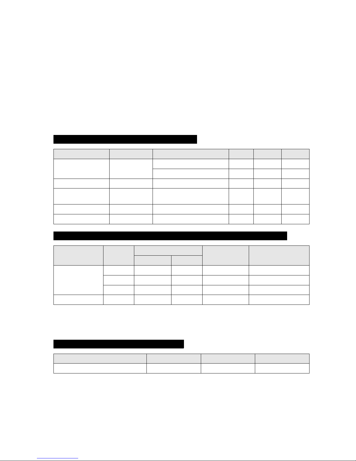
3.3 Setting the Cutter-Pen Conditions
Before starting cutting, set the TOOL (cutter blade or pen), cutter-blade length, OFFSET, FORCE, SPEED,
and QUALITY settings to ensure the optimal cutting conditions.
(1) TOOL (cutter blade or pen): Set to suit the material to be cut.
(2) Cutter-blade length: Adjust the blade length by referring to the media thickness table below.
For details on adjusting the blade length, see “2.4 Adjusting and
Mounting the Cutter Pen.”
(3) OFFSET: Set to suit the cutter blade being used.
(4) FORCE: Set the FORCE by referring to the table below.
(5) SPEED: Set the SPEED by referring to the table below.
(6) QUALITY: Set the QUALITY by referring to the table below.
When the TOOL (cutter blade or pen) has been selected from among “09U,” “15U,” and “15B,” the OFF-
SET is automatically adjusted by ±5 with respect to the default cutter offset v alue f or that b lade type . Select
the PEN setting for plotting using a pen. When the PEN setting is selected, no OFFSET setting is required.
Optimal Cutting Conditions for Each Media Type
Media type Thickness (mm) Blade used FORCE SPEED QUALITY
Film for outdoor use 0.05 to 0.08 CB09UA 10 to 14 30 or less 2
CB15UB (for small-letter cutting) 10 to 14 20 or less 1
Film for decorative use 0.08 to 0.1 CB09UA 14 to 17 30 or less 2
Transparent or
semi-transparent film
0.08 to 0.1 CB09UA 14 to 20 30 or less 2
Reflective film 0.08 to 0.1 CB09UA 14 to 20 30 or less 2
Fluorescent film 0.20 to 0.25 CB09UA, CB15U 20 to 21 20 or less 1
Blade Part Nos., Displayed Blade Types, and Displayed CUTTER OFFSET Values
Blade material Part No.
LCD display indication
Specifiable range Initial CUTTER OFFSET
Blade type Default
Supersteel blades CB09UA 09U 0 ±5 18
CB15U 15U 0 ±5 28
CB15UB 15B 0 ±5 5
Pens Pen —— 0
Reference Pen Conditions for Plotting Pens
Pen type FORCE SPEED QUALITY
Water-based fiber-tip pen 10 to 12 30 2
Page 34
3 – 6
To preserve the pen life, set the FORCE to the lowest setting, and set the SPEED after checking to confirm
that there are no faint lines or other problems during plotting.
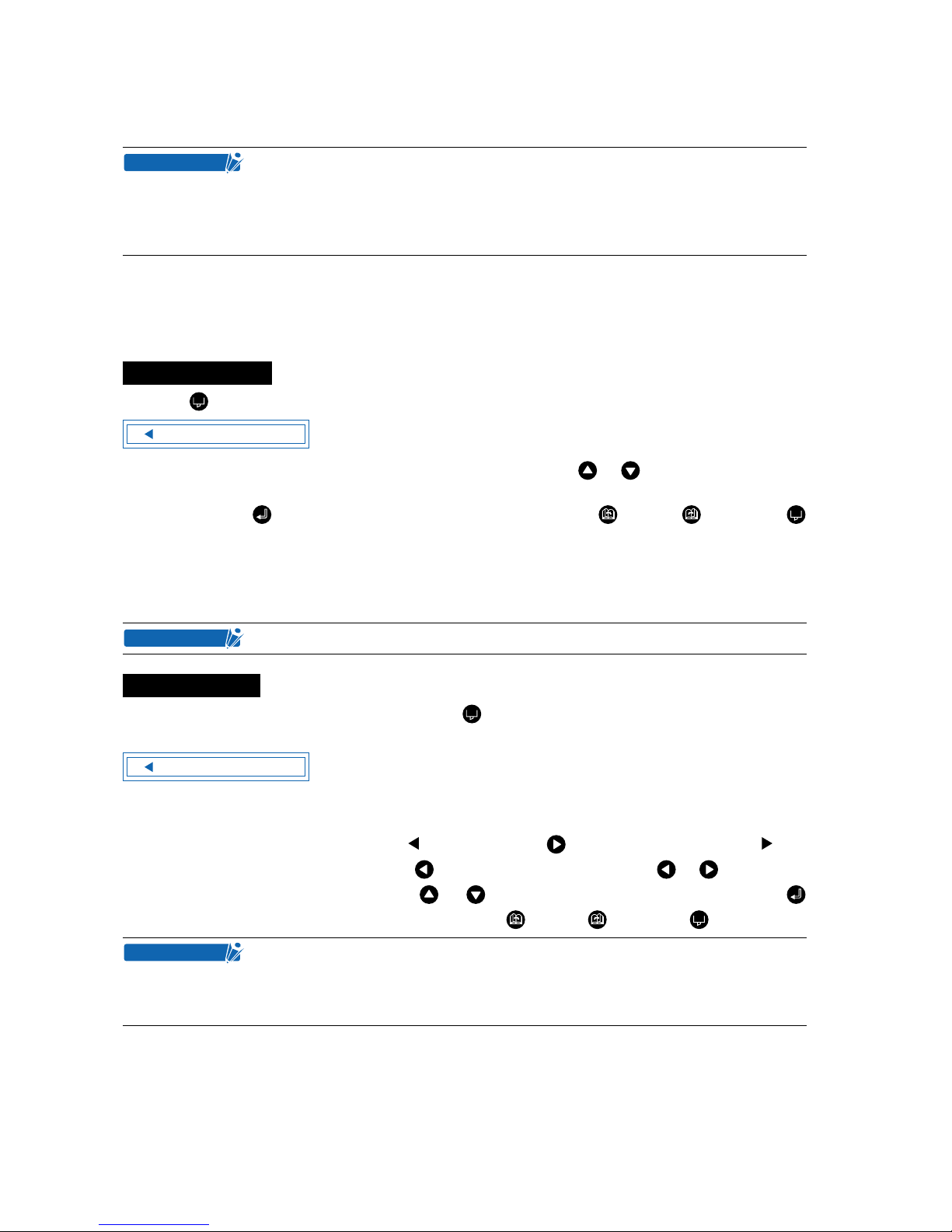
■ Selecting Cutter-Pen-Condition Setting Areas
To set the cutter-pen conditions, first select the setting area (condition number). Switching between these
setting areas enables any of up to eight predefined media types to be selected easily.
Press the (COND.) key in READY mode to display the cutter-pen conditions.
To select condition settings that have previously been stored, use the or key to select the desired
condition number stored on the cutter-pen-condition settings display (the number at the left of the display),
and then press the (ENTER) key. To cancel the selection, press the (NEXT), (PREV.), or
(COND.) key.
■ Storing Cutter-Pen-Condition Setting Areas
The cutter-pen conditions can be stored in nine setting areas numbered “1” to “9.”
To display the cutter-pen conditions, either press the (COND.) key when the cutting plotter is in READY
mode, or when the media set lever is lowered and the buffer is in the empty (cleared) status.
The current settings are displayed (from the left): condition number, PEN TYPE (cutter blade), CUTTER
OFFSET, FORCE, SPEED, and QUALITY.
The item to be changed is indicated by the symbol. Press the key to change the symbol to , and
press again to move it to the right. Press the key to move it to the left. Use the or key to select
the parameter to be changed, and use the or key to select the setting details. Press the
(ENTER) key to confirm. To cancel the selection, press the (NEXT), (PREV.), or (COND.) key.
• If the SPEED and QUALITY settings are set to high values, the cut/plotted
results will have a coarser finish, but the overall cutting/plotting time will be
reduced.
• If the SPEED and QUALITY settings are set to low values, the cut/plotted results
will have a finer finish, but the overall cutting/plotting time will be longer.
Selection method
Data from the controller is used for condition number 9.
Storage method
When using the optional registration mark scanner, condition settings 1 and 2 are
used for the pen settings when performing “Adjusting the Registration-mark Reading Sensor (2)” (refer to page 4-17). It is therefore more convenient if the cutter pen
settings are assigned to 3 to 8 first.
CHECKPOINT
2 09U +1 23 30 2
CHECKPOINT
2 09U +1 23 30 2
CHECKPOINT
Page 35
3 – 7
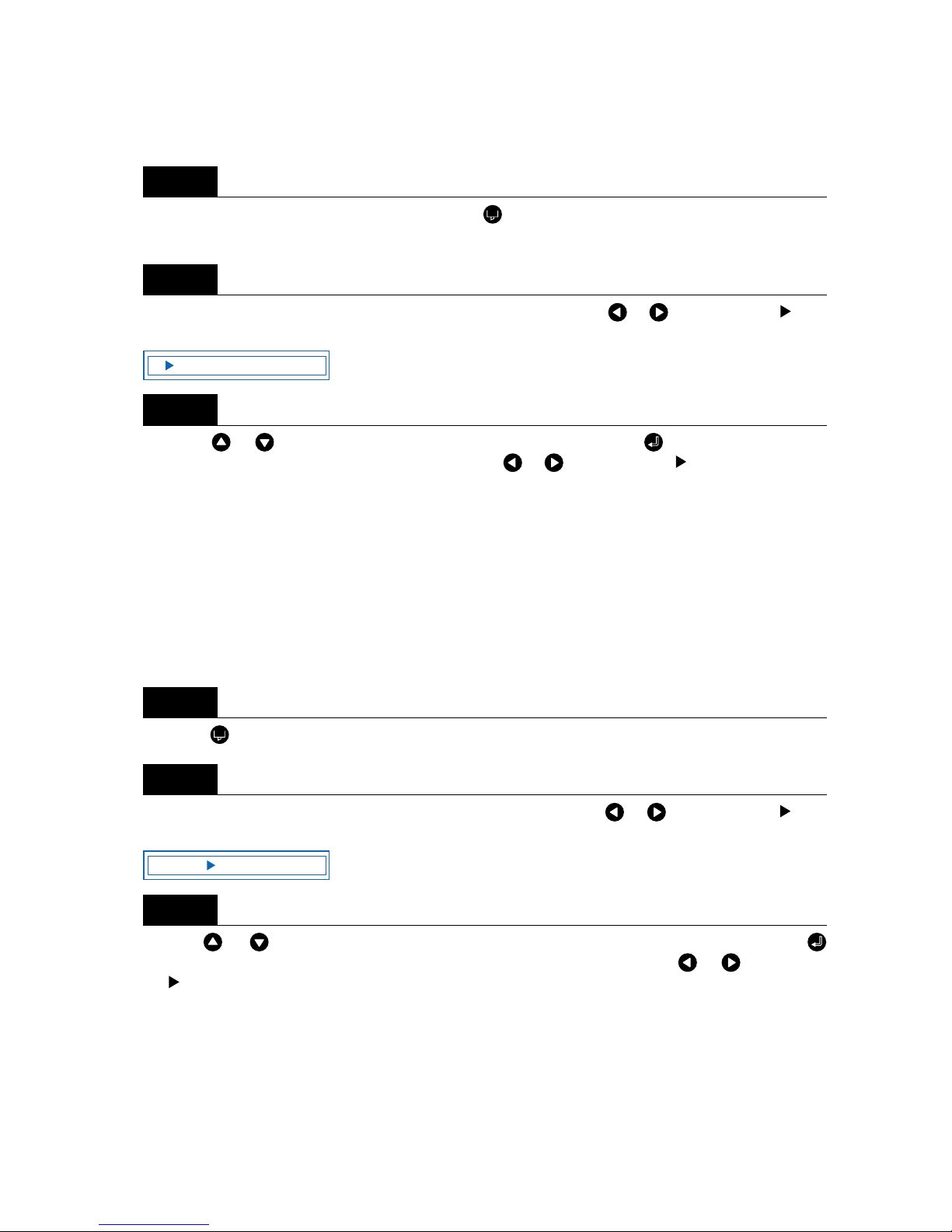
■ Setting TOOL (cutter blade or pen)
Set the type of pen (cutter blade) to be used.
To display the cutter-pen conditions, either press the (COND.) key when the cutting plotter is in READY
mode, or when the media set lever is lowered and the buffer is in the empty (cleared) status.
Select the setting area (condition number) to be set, and then press the or key to mo v e the sym-
bol to the position shown below.
Press the or key to select “09U,” “15U,” “15B,” or “PEN.” Press the (ENTER) key to confirm
the selection. If other conditions are to be set, press the or key to move the symbol to the param-
eter to be set.
■ Setting OFFSET
This setting adjusts the offset of the cutter blade to suit the blade type used. The tip of the blade mounted
in the cutter-pen plunger is not positioned at the center of the pen, so correction is required. This correction
is referred to as the OFFSET setting. The cutting plotter has been preset with OFFSET values for each cutter-blade type. Selecting “09U,” “15U,” or “15B” for the PEN TYPE setting also sets the appropriate OFF-
SET, allowing fine adjustment within the range of ±5. When the “PEN” setting is selected, the OFFSET
cannot be set.
Press the (COND.) key in READY mode to display the cutter-pen conditions.
Select the setting area (condition number) to be set, and then use the or key to move the sym-
bol to the position shown below.
Use the or key to select the value to be changed in the range of “-5” to “+5.” Press the
(ENTER) key to confirm the selection. If other conditions are to be set, press the or key to move
the symbol to the parameter to be set.
Step
1
Step
2
Step
3
Step
1
Step
2
Step
3
2 09U +1 23 30 2
2 09U +1 23 30 2
Page 36

3 – 8
■ Setting FORCE
Sets the pressure applied by the cutter pen during cutting. Set the FORCE value based on the guidelines
in the table entitled “Optimal Cutting Conditions for Each Media Type” on page 3-5.
Press the (COND.) key in READY mode to display the cutter-pen conditions.
Select the setting area (condition number) to be set, and then use the or key to move the symbol
to the position shown below.
Press the or key to select the value to be changed in the range specified below.
“1” to “31”
Press the (ENTER) key to confirm the selection. If other conditions are to be set, press the or
key to move the symbol to the parameter to be set.
■ Setting SPEED
Sets the speed used for cutting. Set the SPEED value based on the guidelines in the table entitled “Opti-
mal Cutting Conditions for Each Media Type” on page 3-5.
Press the (COND.) key in READY mode to display the cutter-pen conditions.
Select the setting area (condition number) to be set, and then use the or key to move the symbol
to the position shown below.
Press the or key to select the value to be corrected in the range specified below.
“1” to “45”
For all cutting plotters, “1” to “10” is in increments of 1, and “10” to “45” is in increments of 5.
Press the (ENTER) key to confirm the selection. If other conditions are to be set, press the or
key to move the symbol to the parameter to be set.
Step
1
Step
2
Step
3
Step
1
Step
2
Step
3
2 09U +1 23 30 2
2 09U +1 23 30 2
Page 37
3 – 9
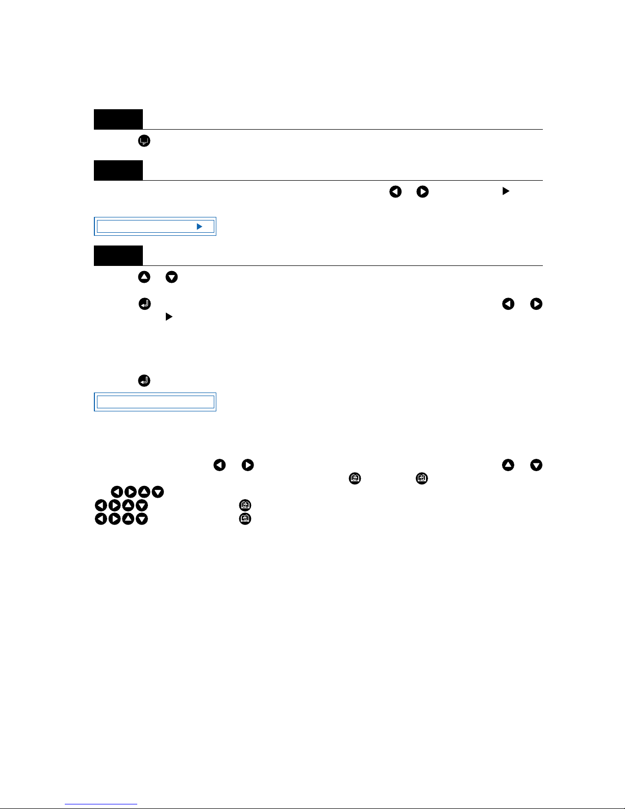
■ Setting QUALITY
Sets the acceleration used in cutting.
Press the (COND.) key in READY mode to display the cutter-pen conditions.
Select the setting area (condition number) to be set, and then use the or key to move the symbol
to the position shown below.
Press the or key to select the value to be changed in the range specified below
“1”, “2”, “3”
Press the (ENTER) key to confirm the selection. If other conditions are to be set, press the or
key to move the symbol to the parameter to be set.
3.4 Displaying the Effective Cutting Area
Press the (ENTER) key in READY mode to display the current effective cutting area.
3.5 Moving the Pen
In READY mode, press the or key to move the pen carriage to the left or right, and the or
key to feed the medium backward or forward. Pressing the (NEXT), or (PREV.) key together with
the (POSITION) keys enables high-speed or low-speed movement.
(POSITION) keys + (NEXT) key: High-speed movement
(POSITION) keys + (PREV.) key: Low-speed movement
Step
1
Step
2
Step
3
2 09U +1 23 30 2
X 0000mm Y 000mm
Page 38
3 – 10
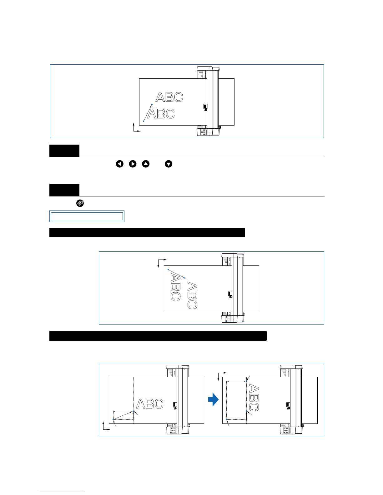
3.6 Setting the Initial Cutting Position (Origin Point)
This function allows the starting position for cutting or plotting to be moved to the desired position.
In READY mode, use the , , , and (POSITION) keys to move the cutter pen to the new origin
point.
Press the (ORIGIN) key. The following menu is displayed and the new origin is set.
Moving the origin when the coordinate axes have been rotated gives the following results.
When the coordinate axes are rotated after the origin point is moved, the origin point is reset as shown in
the figure below. The distance “a” is retained, but the distance “b” is reset.
Step
1
Step
2
When the Origin is Moved After Rotating the Coordinate Axes
When the Coordinate Axes are Rotated After Moving the Origin Point
Original origin
New origin
Y
X
ORIGIN PT SET
Original origin
New origin
X
Y
a
Origin moved
a
b
b
Origin moved
after rotation
X
Y
Y
X
Original origin
Origin moved
Original origin
Origin moved Rotation
Page 39

3 – 11
When it is necessary to both move the origin and rotate the coordinate axes, be sure to rotate the coordinate axes first.
3.7 Stop Function
Cutting or plotting can be stopped by pressing the (PAUSE) key while cutting or plotting is in progress.
The operation selection menu is displayed on the control-panel screen while cutting or plotting is stopped,
enabling operations to be resumed or aborted as required. Raising or lowering the media set lever while
the cutting or plotting is stopped does not require the medium to be selected, so the medium can be
replaced or reset.
Press the (PAUSE) key while cutting or plotting is in progress to stop cutting or plotting and display the
PAUSE menu.
Pressing the (PAUSE) key while cutting or plotting is stopped cancels the pause function and restarts
cutting or plotting. To completely abort cutting or plotting, stop sending data from the computer or press the
(NEXT) or (PREV.) key until the following menu is displayed.
Press the (ENTER) key to display the buffer memory clear menu.
Press the or key to select “YES” or “NO.” To abor t cutting or plotting, select “YES” and press the
(ENTER) key. To cancel, select “NO” and either press the (ENTER) ke y or press the (NEXT) or
(PREV.) key.
Press the (PAUSE) key to reset PAUSE mode.
After a new origin point is set, the displayed coordinate values of X= and Y= represent the respective distances from the new origin.
Step
1
Step
2
Step
3
Step
4
Step
5
CHECKPOINT
FEED
CLEAR BUFFER
CLEAR <YES>
Page 40
3 – 12
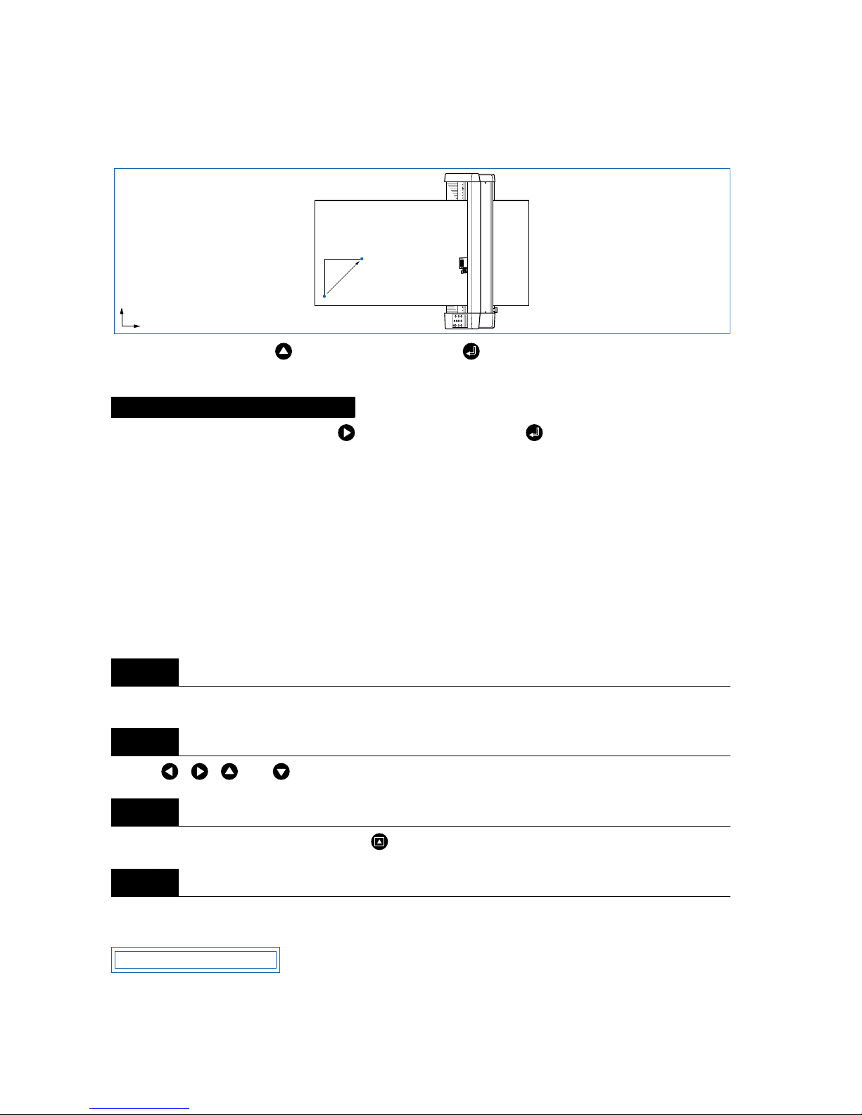
3.8 Moving the Pen Carriage in +100 mm Steps
This function allows the pen carriage to be moved from its current position in +100 mm steps along the Xand Y -ax es.
In READY mode, press the key while holding down the (ENTER) key to move the pen carriage in
+100 mm steps along the X- and Y-axes.
In READY or PAUSE mode, press the key while holding down the (ENTER) key to return the pen
carriage to the origin.
3.9 Test Cutting
Test cutting can be performed after selecting the TOOL (cutter blade) and specifying the cutter-blade
length, OFFSET, FORCE, SPEED, and QUALITY settings to ensure that the selected cutting conditions
actually produce the desired cutting results. Chec k ho w far the blade cuts into the film and how corners are
being cut; if the cutting results are not satisfactory, reset the cutting conditions and repeat the test cutting
until the optimal settings are achieved. If you perform test cutting while the cutter-pen conditions are being
set, the test cutting will be performed under the conditions being set.
Load the medium for test cutting on the cutting plotter.
Use the , , , and (POSITION) keys to move the pen carriage to the position for test cutting.
Switch to READY mode, and then press the (TEST) key.
When test cutting has been completed, the pen carriage moves to the standby position and the following
menu is displayed.
Returning to the original position
Step
1
Step
2
Step
3
Step
4
Original pen-carriage position
Moved pen-carriage
position
Y
X
100mm
100mm
PRESS ENTER KEY
Page 41
3 – 13
Press the (ENTER) key to return the pen carriage to its previous position and to switch the cutting plotter to READY mode.
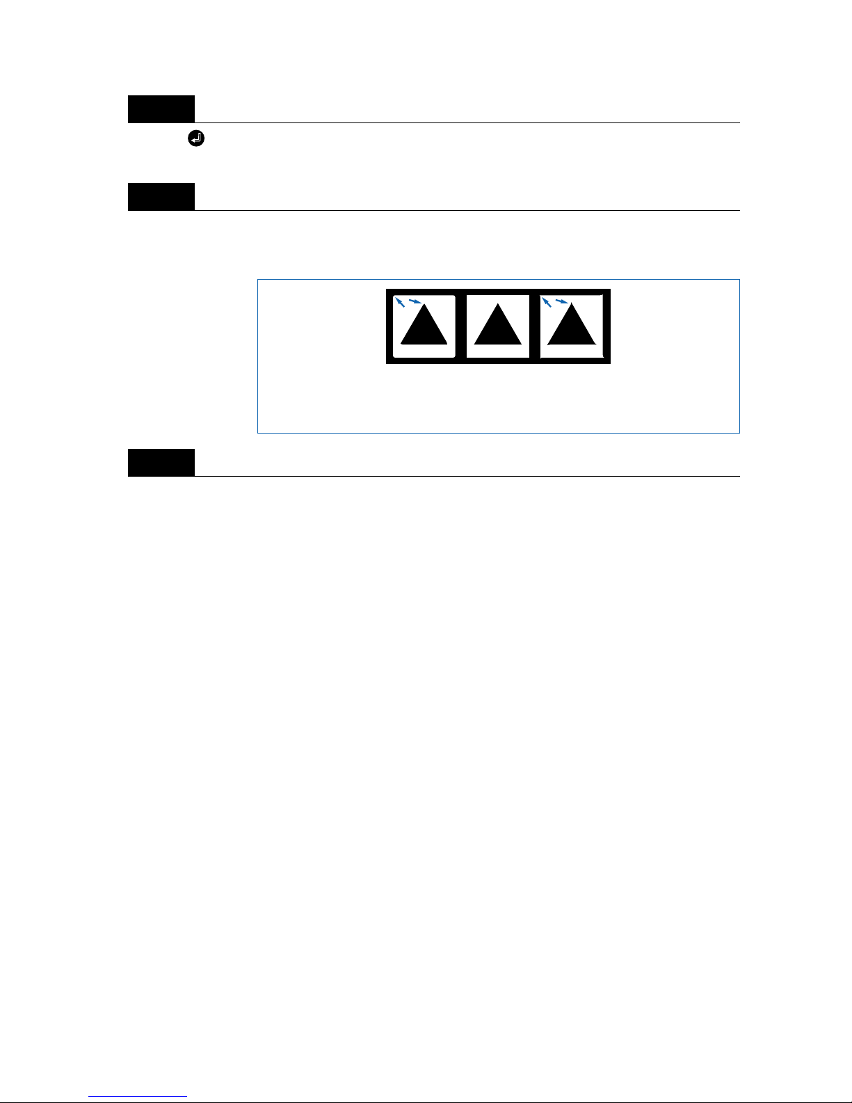
Adjust the CUTTER OFFSET value to suit the type and thickness of the medium being used, and fine-
adjust the finish of each corner. Set the FORCE so that only faint cutting lines remain on the base sheet
when the blade length is properly adjusted.
Upon completion of fine adjustment, actual cutting data can be sent to the cutting plotter.
Step
5
Step
6
Step
7
CUTTER
OFFSET
is too low
Increase
(by +1 to +5)
Correct
CUTTER
OFFSET
setting
CUTTER
OFFSET
is too high
Decrease
(by -1 to -5)
Page 42

3 – 14
Page 43

4
4
FUNCTION SETTINGS AND OPERATIONS
4.1 PAUSE Menu List........................................................................4-2
4.2 Reading the Auto Registration Marks
(Option).............................................................................................4-3
4.3 Setting the FEED function.......................................................4-4
4.4 Setting AUTO PRE-FEED .........................................................4-5
4.5 Setting T ANGENTIAL Mode.....................................................4-6
4.6 Auto-Registration-Mark-Reading Settings
(Option).............................................................................................4-8
4.7 Clearing the Buffer Memory..................................................4-21
4.8 Aligning the Coordinate Axes..............................................4-22
4.9 Distance Adjustment...............................................................4-24
4.10 Setting the PAGE LENGTH....................................................4-26
4.11 Setting the Cutting/Plotting Area........................................4-27
4.12 Expanding the Cutting/Plotting Area.................................4-28
4.13 Rotating the Coordinate Axes..............................................4-29
4.14 Mirroring......................................................................................4-30
4.15 Cutting/Plotting Using the Buffer Memory
(COPY Function)............................................................................4-31
4.16 Sorting Settings........................................................................4-33
4.17 Interface Settings .....................................................................4-34
4.18 Setting the Format of Data to be Received.....................4-35
4.19 Blade Wear Detection (When Blade Wear Setup is On) ......4-37
4.20 Raising and Lowering the Pen.............................................4-41
4.21 TEST Mode..................................................................................4-42
4.22 Setting the PEN UP SPEED...................................................4-46
4.23 Setting the OFFSET FORCE (Initial Cutting Force) ..........4-47
4.24 Setting the OFFSET ANGLE.................................................4-48
4.25 Setting the STEP PASS...........................................................4-49
4.26 Setting the Initial Down Force..............................................4-50
4.27 Setting the LENGTH UNIT......................................................4-51
Page 44
4 – 2
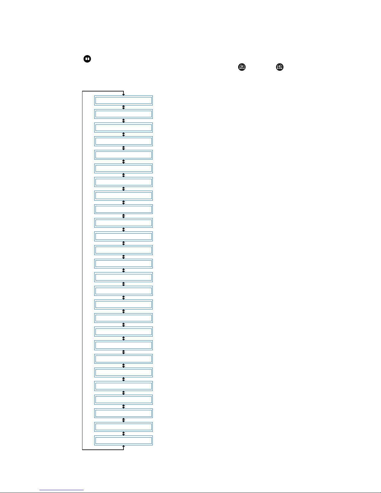
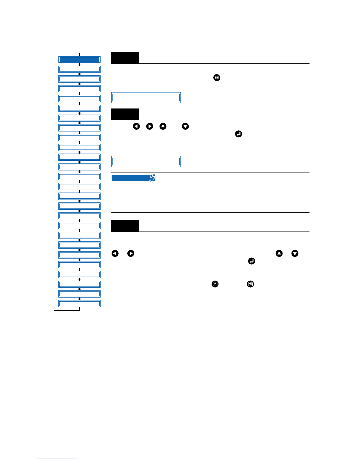
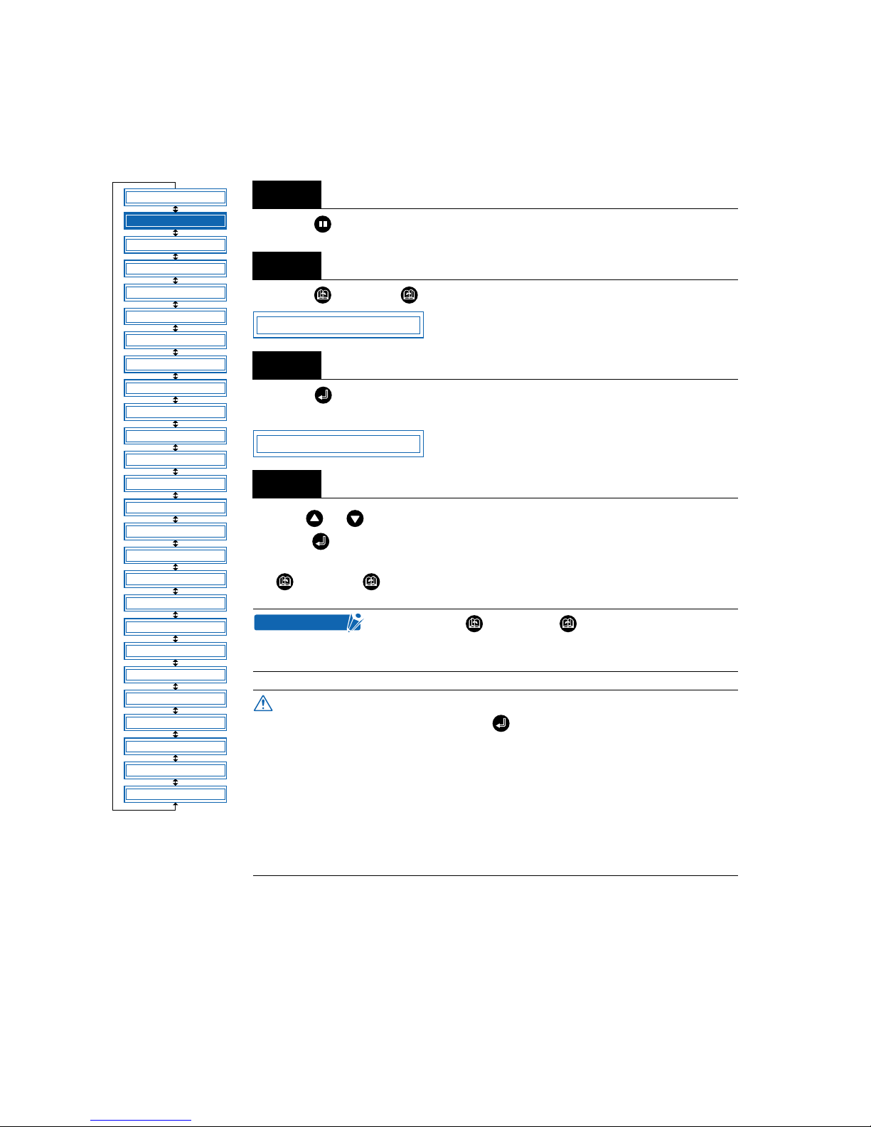
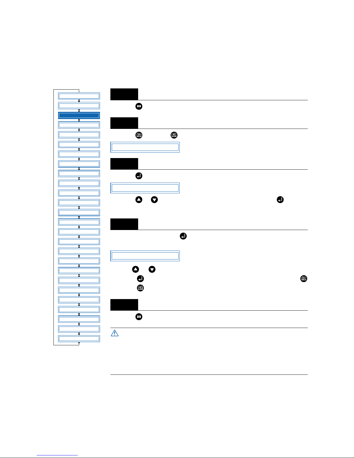
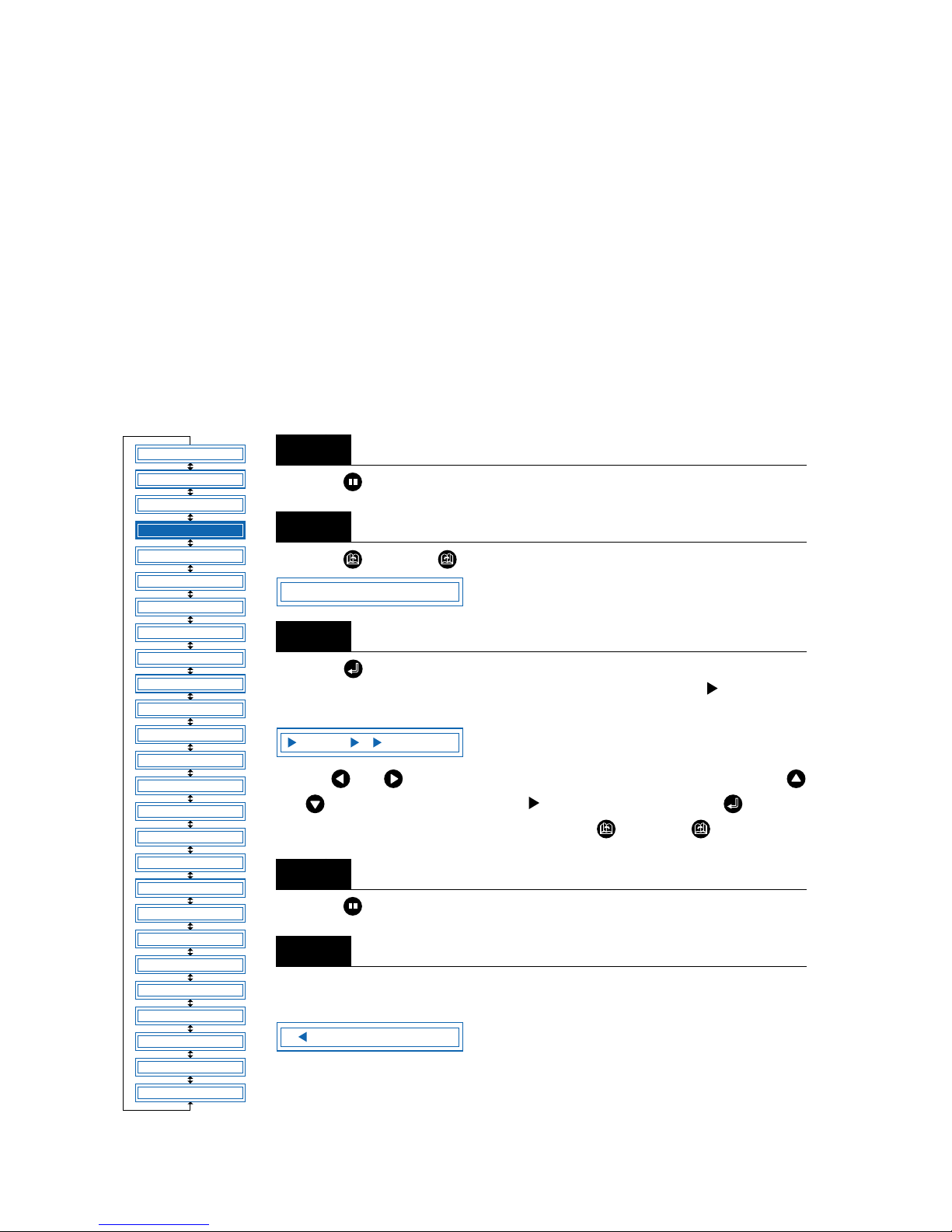
4.1 PAUSE Menu List
Pressing the (PAUSE) key in READY mode displays the PAUSE menu, enab ling the various settings to
be made. Select the required menu by scrolling through the list using the (NEXT) or (PREV.) key.
Note: “MOVE TO R. MARK” is applied only for RMS model (Option).
“AUTO REG. MARK” is applied only for RMS model (Option).
FEED
MOVE TO R. MARK
AUTO PRE FEED
TANGENTIAL
AUTO REG. MARK
CLEAR BUFFER
AXIS ALIGNMENT
DISTANCE ADJUST
PAGE LENGTH
PLOT AREA
EXPAND
ROTATE
MIRROR
COPY
SORT
RS-232C
COMMAND
BLADE WEAR SETUP
PEN UP/DOWN
TEST
PEN UP SPEED
OFFSET FORCE
OFFSET ANGLE
STEP PASS
INIT. DOWN FORCE
LENGTH UNIT
4.2 Reading the Auto Registation Marks (Option)
4.3 Setting the FEED function
4.4 Setting the AUTO PRE-FEED
4.5 Setting T ANGENTIAL Mode
4.6 Auto-Registration-Mark-Reading Settings
(Option)
4.7 Clearing the Buffer Memory
4.8 Aligning the Coordinate Axes
4.9 Distance Adjustment
4.10 Setting the PAGE LENGTH
4.11 Setting the Cutting/Plotting Area
4.12 Expanding the Cutting/Plotting Area
4.13 Rotating the Coordinate Axes
4.14 Mirroring
4.15 Cutting/Plotting Using the Buffer Memory
(COPY Function)
4.16 Sorting Settings
4.17 Interface Settings
4.18 Setting the Format of Data to be Received
4.19 Cutter-Blade Wear Detection
(Special function only displayed for BLADE WEAR SETUP “ON’)
4.20 Raising and Lowering the Pen
4.21 TEST Mode
4.22 Setting the PEN UP SPEED
4.23 Setting the OFFSET FORCE (Initial Cutting Force)
4.24 Setting the OFFSET ANGLE
4.25 Setting the STEP PASS
4.26 Setting the INITIAL DOWN FORCE
4.27 Setting the LENGTH UNIT
Page 45
4 – 3
4.2 Reading the Auto Registration Marks (Option)
When “2 POINT,” “3 POINT,” or “4 POINT” has been set (see “4.6 Auto-Registra-
tion-Mark-Reading Settings”), press the (PAUSE) key to switch to PAUSE
mode and display the following menu.
Use the , , , and (POSITION) keys to move the cutter pen to the
lower-right registration mark, and then press the (ENTER) key. The sensor
reads between points 1 and 2 (and also between points 1 and 3 for 3-point alignment or 4-point alignment), and the following is displayed.
The distance between X-axis registration marks (points 1 and 2) read by the cutting plotter is displayed on the left. Enter the actual distance on the right. Use the
or key to move the cursor to the digit to be entered, use the or key
to increase or decrease the values, and then press the (ENTER) key to confirm. For 3-point alignment or 4-point alignment, the distance between the Y-axis
registration marks (points 1 to 3) is also displayed and should be set in the same
way. To cancel the selection(s), press the (NEXT) or (PREV.) key.
Step
1
Step
2
• If the registration-mark distance correction is set to
“5 mm,” “10 mm,” “50 mm,” or “STD.” the alignment
input screen is not displayed.
• The registration marks are read in accordance with the
registration-mark-detection movement distance setting.
Step
3
FEED
MOVE TO R. MARK
AUTO PRE FEED
TANGENTIAL
AUTO REG. MARK
CLEAR BUFFER
AXIS ALIGNMENT
DISTANCE ADJUST
PAGE LENGTH
PLOT AREA
EXPAND
ROTATE
MIRROR
COPY
SORT
RS-232C
COMMAND
BLADE WEAR SETUP
PEN UP/DOWN
TEST MODE
PEN UP SPEED
OFFSET FORCE
OFFSET ANGLE
STEP PASS
INIT. DOWN FORCE
LENGTH UNIT
*
*
*: Option
MOVE TO R. MARK
X00308.9 00308.9
CHECKPOINT
Page 46
4 – 4
4.3 Setting the FEED function
The FEED function feeds the medium forw ard and bac kward to leave f aint tracks of the grit rollers on it and
prevent the media from slipping during a cutting or plotting operation.
Press the (PAUSE) key to switch to PAUSE mode.
Press the (NEXT) or (PREV.) key until the following menu is displayed.
Press the (ENTER) key to display the feed-length setting. Set the length to be
fed.
Use the or key to set a value within the range of 1 m to 50 m, and then
press the (ENTER) key. The cutting plotter performs the feed operation (mov es
the medium forward and then back to the origin). To cancel the operation, press
the (NEXT) or (PREV.) key.
Step
1
Step
2
Step
3
Step
4
Pressing the (NEXT) or (PREV.) key during the
feed operation aborts the feed operation and returns the
medium to its original position.
• The feed operation starts immediately once the feed length
has been set and the (ENTER) key is pressed. Make sure
there are no obstructions at the front or rear of the cutting plotter.
• When using roll media, either extend and load the length to be
used beforehand or use the media feed procedure (“4.3 Setting the FEED function”, “4.4 Setting AUTO PRE-FEED”).
Beginning cutting or plotting without feeding the media first
may generate a position error or may cause the roll media to
fall off the stock shaft.
FEED
MOVE TO R. MARK
AUTO PRE FEED
TANGENTIAL
AUTO REG. MARK
CLEAR BUFFER
AXIS ALIGNMENT
DISTANCE ADJUST
PAGE LENGTH
PLOT AREA
EXPAND
ROTATE
MIRROR
COPY
SORT
RS-232C
COMMAND
BLADE WEAR SETUP
PEN UP/DOWN
TEST MODE
PEN UP SPEED
OFFSET FORCE
OFFSET ANGLE
STEP PASS
INIT. DOWN FORCE
LENGTH UNIT
*
*
*: Option
FEED
FEED 1m
CHECKPOINT
CAUTION
Page 47
4 – 5
4.4 Setting AUTO PRE-FEED
When the AUTO PRE-FEED function is set to “ON,” the medium is automatically fed forward and back-
ward by the preset length when data is received. This operation leaves traces of the grit rollers on the
media and prevents it from slipping during a cutting or plotting operation. Similarly, if roll media is used, the
medium is automatically pulled out by the cutting plotter.
Press the (PAUSE) key to switch to PAUSE mode.
Press the (NEXT) or (PREV.) key until the following menu is displayed.
Press the (ENTER) key to display the AUTO PRE-FEED setting.
Press the or key to select “ON” or “OFF,” and then press the (ENTER)
key to confirm.
If “ON” is selected and the (ENTER) key pressed, the feed-length setting is
displayed.
Use the or key to set a value within the range of 1 m to 50 m, and then
press the (ENTER) key to confirm. To cancel the selection, press the
(NEXT) or (PREV.) key.
Press the (PAUSE) key to cancel PAUSE mode.
Step
1
Step
2
Step
3
Step
4
Step
5
When using roll media, either extend and load the length to be
used beforehand or use the media feed procedure (“4.3 Setting
the FEED function”, “4.4 Setting AUTO PRE-FEED”).
Beginning cutting or plotting without feeding the media first may
generate a position error or may cause the roll media to fall off
the stock shaft.
FEED
MOVE TO R. MARK
AUTO PRE FEED
TANGENTIAL
AUTO REG. MARK
CLEAR BUFFER
AXIS ALIGNMENT
DISTANCE ADJUST
PAGE LENGTH
PLOT AREA
EXPAND
ROTATE
MIRROR
COPY
SORT
RS-232C
COMMAND
BLADE WEAR SETUP
PEN UP/DOWN
TEST MODE
PEN UP SPEED
OFFSET FORCE
OFFSET ANGLE
STEP PASS
INIT. DOWN FORCE
LENGTH UNIT
*
*
*: Option
AUTO PRE FEED
AUTO PRE FEED ON
AUTO PRE FEED 1m
CAUTION
Page 48
4 – 6
4.5 Setting TANGENTIAL Mode
This function should be used for the cutting of thick media (more than 0.3 mm in thickness) and when the
cutter blade is not able to turn properly due to the cutting depth, resulting in discrepancies between the
start and finish point and the inability to cut sharp corners. This function can be set on or off individually for
each of the eight cutter-pen setting areas, and it should be set to suit the media used. The overcut-amount
setting screen is displayed for cutter-pen setting areas for which the TANGENTIAL mode is “ON.”
This setting has two modes: Mode 1 and Mode 2.
Mode 1: Overcuts the start and finish cutting positions and acute-angle cor ner sections to avoid leaving
uncut sections. In addition, the cutter blade is moved on the surface of the medium during cutting
when it is rotated significantly, ensur ing sharp cutting unaffected by the medium toughness or
thickness.
Mode 2: Overcuts the start and finish cutting positions only . In addition, the cutter is rotated on the medium
surface for the start cutting position only. This uses simpler cutter control than Mode 1, and provides a shorter cutting time.
Press the (PAUSE) key to switch to PAUSE mode.
Press the (NEXT) or (PREV.) key until the following menu is displayed.
Press the (ENTER) key to display the TANGENTIAL setting. The numbers “1”
to “8” indicate the cutter setting areas, and those marked with a symbol have
the TANGENTIAL mode set to “ON.”
Use the and keys to mov e the cursor and select a setting area. Use the
and keys to display/not displa y the symbol, and then press the (ENTER)
key to confirm. To cancel the selection, press the (NEXT) or (PREV.) key
Press the (PAUSE) key to cancel PAUSE mode.
Select the condition-setting area to be set to “ON” (refer to “Selecting Cutter-Pen-
Condition Setting Areas” on page 3-6).
Step
1
Step
2
Step
3
Step
4
Step
5
FEED
MOVE TO R. MARK
AUTO PRE FEED
TANGENTIAL
AUTO REG. MARK
CLEAR BUFFER
AXIS ALIGNMENT
DISTANCE ADJUST
PAGE LENGTH
PLOT AREA
EXPAND
ROTATE
MIRROR
COPY
SORT
RS-232C
COMMAND
BLADE WEAR SETUP
PEN UP/DOWN
TEST MODE
PEN UP SPEED
OFFSET FORCE
OFFSET ANGLE
STEP PASS
INIT. DOWN FORCE
LENGTH UNIT
*
*
*: Option
TANGENTIAL
1 2 3 4 5 6 7 8
5 15U 0 20 30 1
Page 49

4 – 7
Press the (ENTER) key or use the key to move the cursor to the right-hand side, and then press
the key again to display the menu shown below. If the distance adjustment is set for the setting area
selected, the distance adjustment will be displayed here. Either press the (ENTER) key or move the
cursor to the right-hand side and press the key.
Press the or key to select “Mode 1” or “Mode 2,” and then press the (ENTER) key. The over-
cut setting is displayed.
“STR” indicates the initial overcut amount, and “END” indicates the end overcut amount for the line sec-
tion. Press the or key to select “STR” or “END”, use the or key to increase or decrease the
values, and then press the (ENTER) key to confirm. To cancel the selection(s), press the (NEXT) or
(PREV.) key.
Step
6
Step
7
Step
8
TANGENTIAL MODE 1
STR=0.2 END=0.2
Page 50
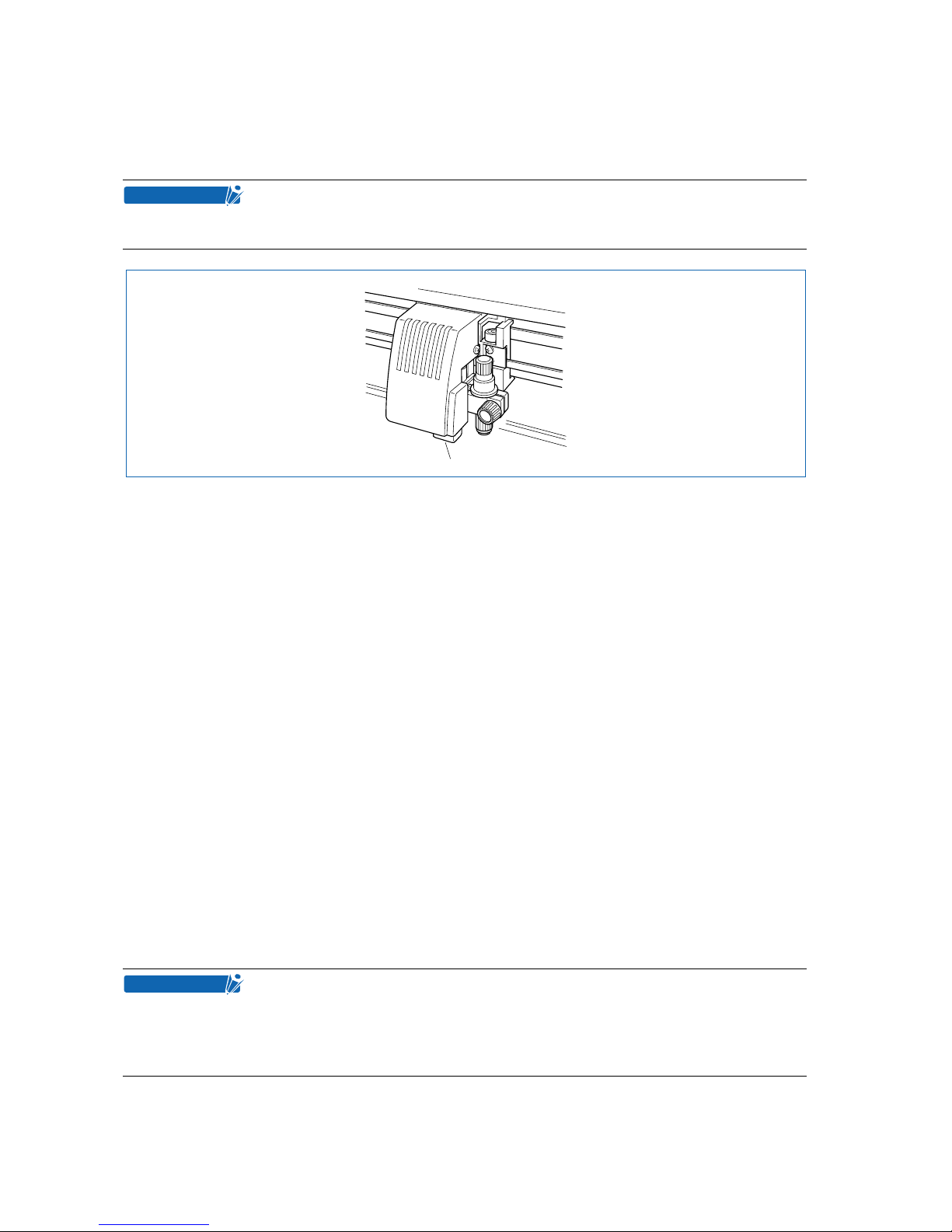
4 – 8
4.6 Auto-Registration-Mark-Reading Settings (Option)
These settings enable pre-plotted media to be cut without any offset by reading the registration marks
using the cutting-plotter sensor and adjusting the axes to suit the coordinate data.
The following precautions must be observed when the registration marks are automatically read.
• Registration-mark pattern
• Reading range required for the detection of registration marks
• Medium and registration-mark position
• Drawing origin point
• Medium type
The registration-mark conditions that can be read by the cutting plotter are as follows.
• Registration-mark line width: 0.3 mm to 1.0 mm (The registration-mark center lines are used as the reference points.)
• Registration-mark size: 5 mm to 20 mm (See “Setting the Registration-mark Size.”)
• Registration-mark pattern: Pattern 1 or 2 (See “Setting the Registration-mark Pattern.”)
• Registration marks must be formed of single lines.
• Registration marks must be drawn in black.
The cutting plotter cannot detect registration marks on the following media types.
• Transparent media: The writing surface is also read, preventing the registration-mark lines
from being read.
• Non-monochrome drawings: The registration marks cannot be read on colored media or if the registra-
tion marks are not black.
• Untidy drawings or media: The registration marks cannot be read if the medium surface is dirty or
creased, or if the registration marks are defaced.
• Medium thickness: The registration marks cannot be read if the medium is more than 0.3 mm
in thickness.
Registration-mark reading accuracy *: Within 0.3 mm
* Accuracy when using pens provided with the cutting plotter, high-grade media,
and reading the specified pattern.
• The registration marks used in the application software cannot be used. The registration marks must always be created as drawing data.
• If auto mark reading is not possible, use the axis alignment function (see “Setting
Axis Alignment”).
• Auto mark reading cannot be performed when MIRROR is set to ON.
CHECKPOINT
Sensor
CHECKPOINT
Page 51
4 – 9
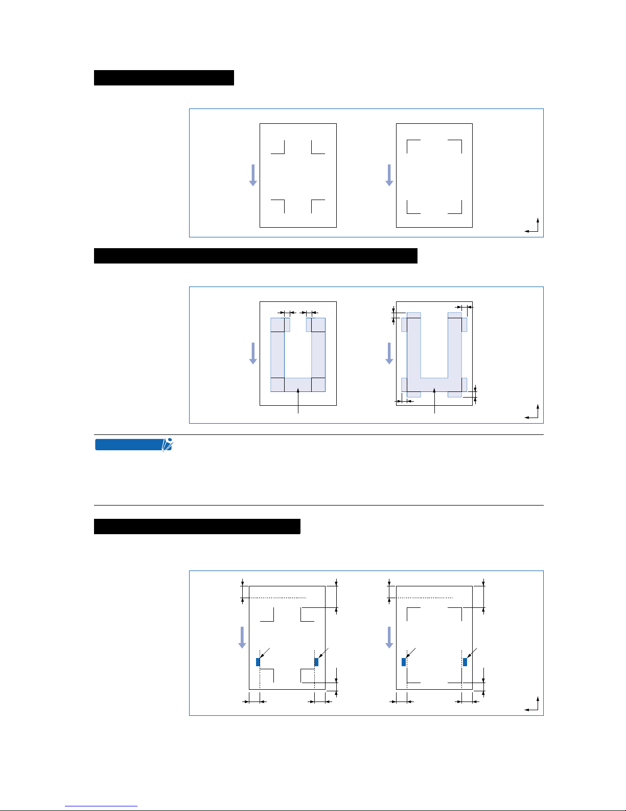
The cutting plotter is capable of reading the following registration-mark patterns.
The range required for the detection of registration marks is as shown below.
Blank margins must be left between the medium edges and the registration marks to enable the marks to
be read.
Note: The margins in parentheses are the blank margins that must be left between the medium edges and
the cutting area in SHEET mode.
Registration-mark pattern
Reading range required for the detection of registration marks
• Incorrect detection may occur if there are marks other than registration marks
within the reading range. If drawings overlap the registration-mark reading range ,
refer to “Setting the Registration-mark detection movement distance.”
• Incorrect detection may occur if the registration-mark reading range is dirty or
foreign matter is adhering to the medium surface.
Medium and registration-mark position
Registration-mark pattern 1
Medium feed direction
Registration-mark pattern 2
X
Y
Registration-mark reading range
a=6mm
a
a
a
a
Registration-mark pattern 2Registration-mark pattern 1
Medium feed direction
X
Y
Registration-mark reading range
a=6mm
a
a
CHECKPOINT
Registration-mark pattern 1
Medium feed direction
Registration-mark pattern 2
Right-hand
push roller
1515
5010
Left-hand
push roller
Right-hand
push roller
1515
50
(30)
(30)
10
Left-hand
push roller
Units: mm
X
Y
Page 52
4 – 10
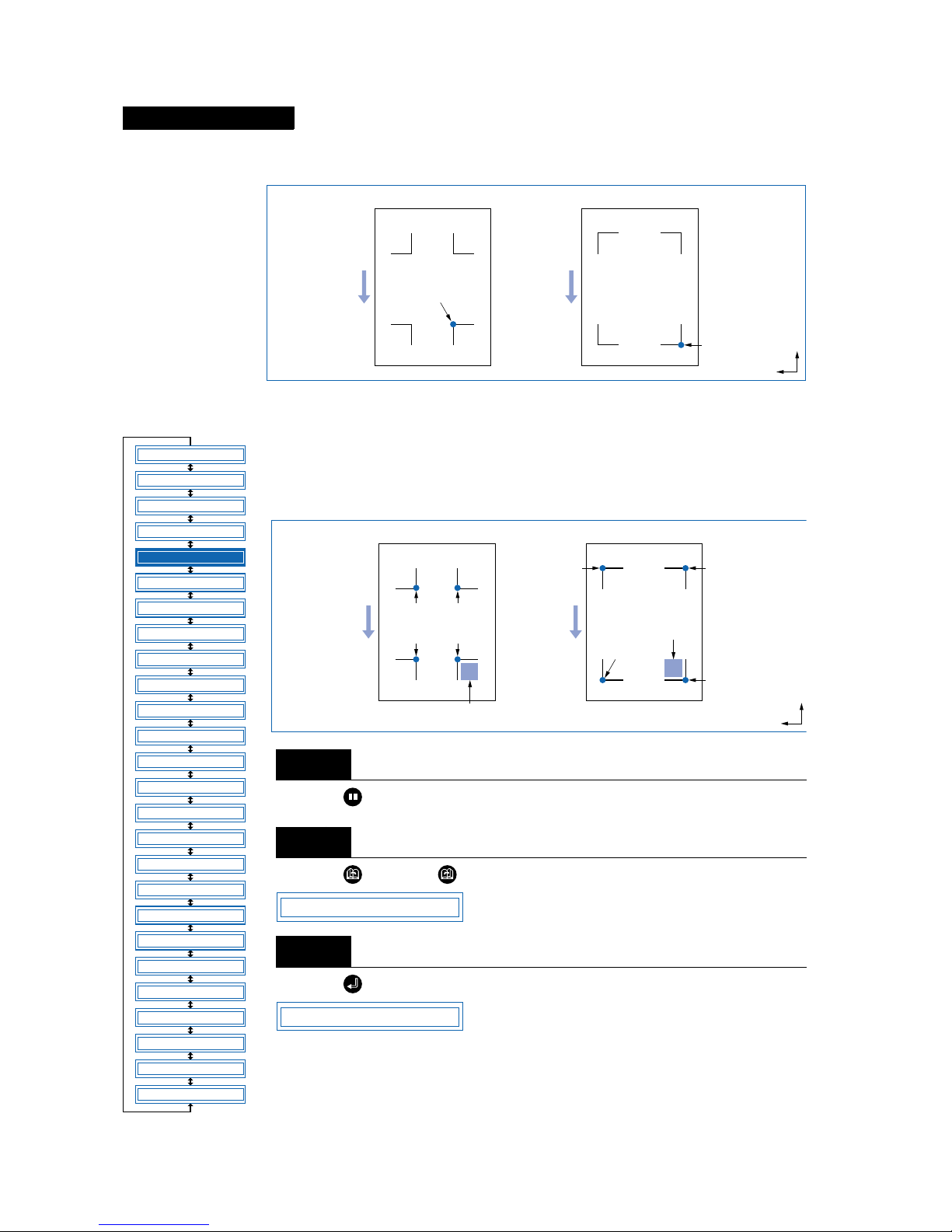
The drawing origin point following reading of the registration marks will be at the bottom-right registration
mark, as shown below.
■ Setting the Registration-Mark Mode
For 2-point alignment, the origin and X-axis registration marks are read; for 3-point
alignment, the origin, X-axis, and Y-axis registration marks are read; and for 4-point
alignment, all four registration marks are read. Axis alignment (correction of any
tilt) and distance adjustment are then performed.
Press the (PAUSE) key to switch to PAUSE mode.
Press the (NEXT) or (PREV.) key until the following menu is displayed.
Press the (ENTER) key to display the Auto Reg. Mark submenu.
Drawing origin point
Step
1
Step
2
Step
3
Registration-mark pattern 1
Medium feed direction
Registration-mark pattern 2
Origin point
Origin point
X
Y
FEED
MOVE TO R. MARK
AUTO PRE FEED
TANGENTIAL
AUTO REG. MARK
CLEAR BUFFER
AXIS ALIGNMENT
DISTANCE ADJUST
PAGE LENGTH
PLOT AREA
EXPAND
ROTATE
MIRROR
COPY
SORT
RS-232C
COMMAND
BLADE WEAR SETUP
PEN UP/DOWN
TEST MODE
PEN UP SPEED
OFFSET FORCE
OFFSET ANGLE
STEP PASS
INIT. DOWN FORCE
LENGTH UNIT
*
*
*: Option
Registration-mark pattern 1
Medium feed direction
Registration-mark pattern 2
Move the cutter
blade within
this area.
Point 1
(Drawing
origin point)
Point 2
Point 4
Point 3
Point 4
Point 1
(Drawing
origin point)
Point 3
Point 2
Move the cutter blade
within this area.
X
Y
AUTO REG. MARK
MARK MODE
Page 53
4 – 11
Press the (ENTER) key to display the MARK mode settings.
Press the or key to select “OFF,” “2 POINT,” “3 POINT,” or “4 POINT,” and then press the
(ENTER) key to confirm.
Press the (PAUSE) key to cancel PAUSE mode.
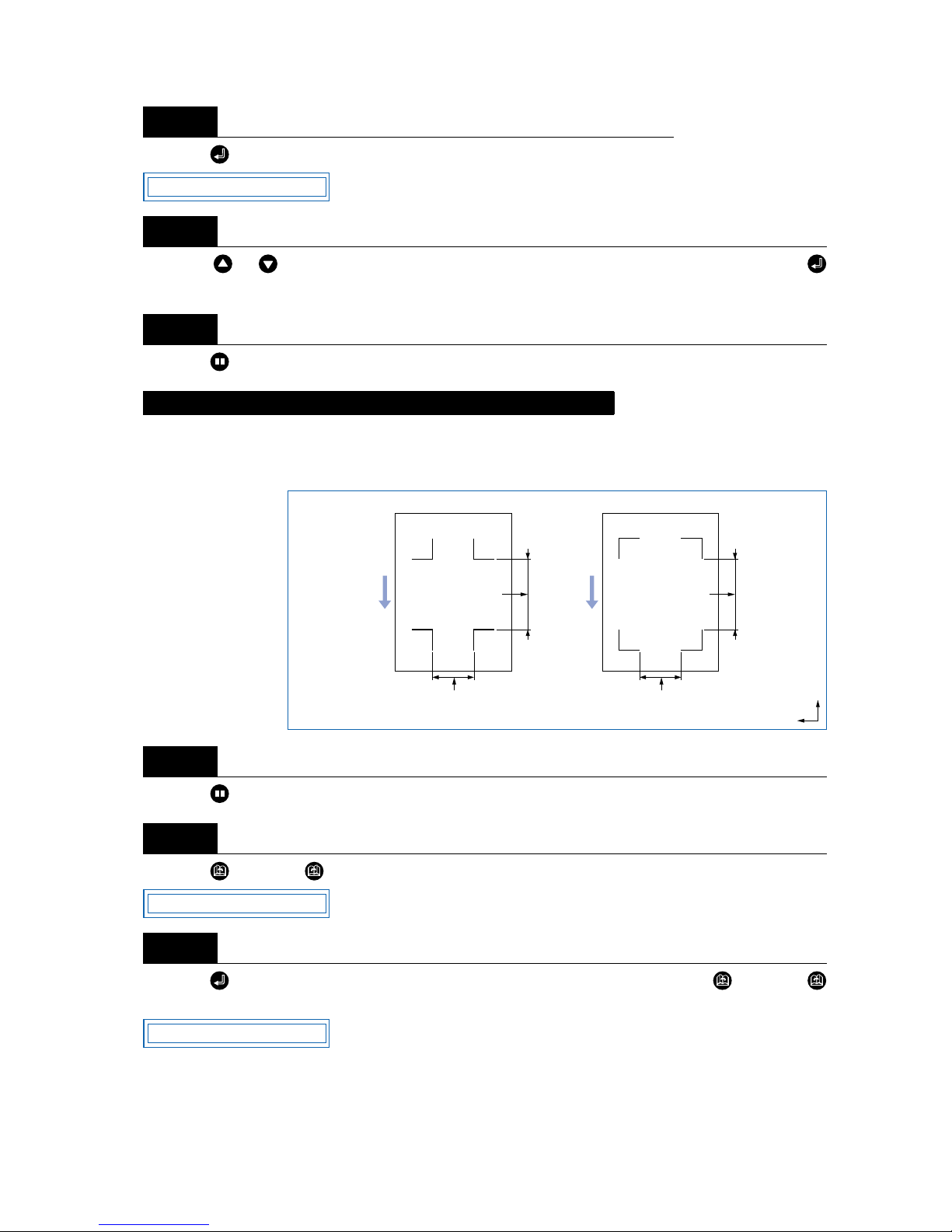
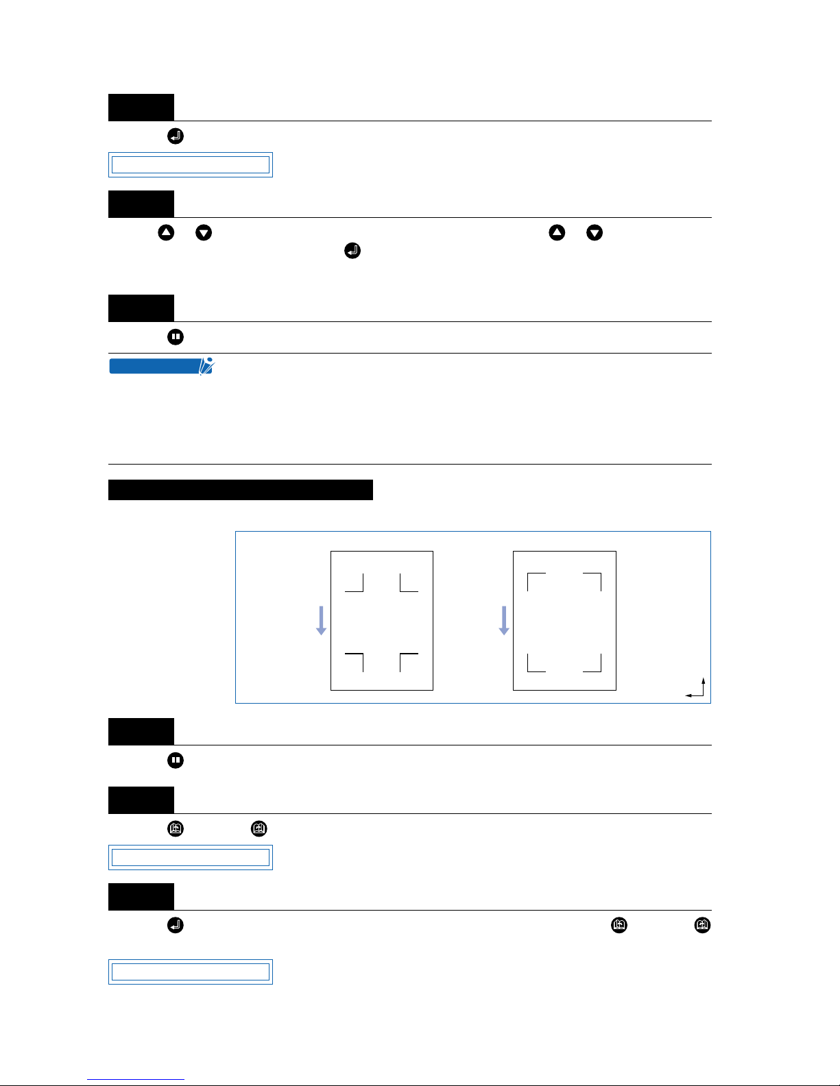
This sets the distance between the registration marks and changes the initial registration-mark scanning
position. Avoiding reading areas that obviously do not include registration marks increases the registrationmark reading speed and minimizes the possibility of incorrect reading due to other marks on the medium.
Press the (PAUSE) key to switch to PAUSE mode.
Press the (NEXT) or (PREV.) key until the following menu is displayed.
Press the (ENTER) key to display the Auto Reg. Mark submenu, and then press the (NEXT) or
(PREV.) key until the following menu is displayed.
Step
4
Step
5
Step
6
Setting the Registration-mark detection movement distance
Step
1
Step
2
Step
3
MARK MODE OFF
Registration-mark pattern 1
Medium feed direction
Registration-mark pattern 2
Set the registrationmark detection
movement distance X
based on this distance.
Set the registration-mark
detection movement distance
Y based on this distance.
Set the registrationmark detection
movement distance X
based on this distance.
Set the registration-mark
detection movement distance
Y based on this distance.
X
Y
AUTO REG. MARK
MARK POSITION
Page 54
4 – 12
Press the (ENTER) key to display the registration-mark detection movement distance X-axis setting.
Use the or key to move the cursor to the digit to be entered, use the or key to increase or
decrease the values, and then press the (ENTER) key to confirm. The Y-axis setting is then displayed
and should be set in the same way.
Press the (PAUSE) key to cancel PAUSE mode.
The cutting plotter is capable of reading the following registration-mark patterns.
Press the (PAUSE) key to switch to PAUSE mode.
Press the (NEXT) or (PREV.) key until the following menu is displayed.
Press the (ENTER) key to display the Auto Reg. Mark submenu, and then press the (NEXT) or
(PREV.) key until the following menu is displayed.
Step
4
Step
5
Step
6
• This setting is retained in the memory even when the power is turned off.
• If the detection movement distance is set to 0 mm, the sensor continues detect-
ing between the registration marks without skipping until it detects the next mark.
• For 2-point alignment, the Y value is ignored.
• The medium will be ejected if the detection movement distance is set to a value
greater than the medium length.
Setting the Registration-mark Pattern
Step
1
Step
2
Step
3
M. POS X=0000mm
CHECKPOINT
Registration-mark pattern 1
Medium feed direction
Registration-mark pattern 2
X
Y
AUTO REG. MARK
MARK TYPE
Page 55
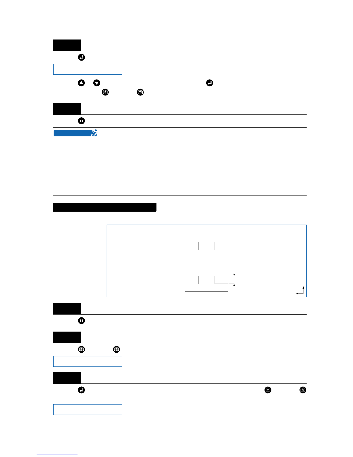
4 – 13
Press the (ENTER) key to display the registration-mark pattern setting.
Press the or key to select “1” or “2,” and then press the (ENTER) key to confirm. To cancel the
selection, press the (NEXT) or (PREV.) key.
Press the (PAUSE) key to cancel PAUSE mode.
This sets the size of the registration marks to be read.
Press the (PAUSE) key to switch to PAUSE mode.
Press the (NEXT) or (PREV.) key until the following menu is displayed.
Press the (ENTER) key to display the Auto Reg. Mark submenu, and then press the (NEXT) or
(PREV.) key until the following menu is displayed.
Step
4
Step
5
The registration-mark conditions that can be read by the cutting plotter are as follows.
• Registration-mark line width: 0.3 mm to 1.0 mm (The registration-mark center
lines are used as the data.)
• Registration-mark size: 5 mm to 20 mm (See “Setting the Registration-mark
Size.”)
• Registration-mark pattern: Pattern 1 or 2
• Registration marks must be formed of single lines.
• Registration marks must be drawn in black.
Setting the Registration-mark Size
Step
1
Step
2
Step
3
MARK TYPE 1
CHECKPOINT
Enter this length
X
Y
AUTO REG. MARK
MARK SIZE
Page 56
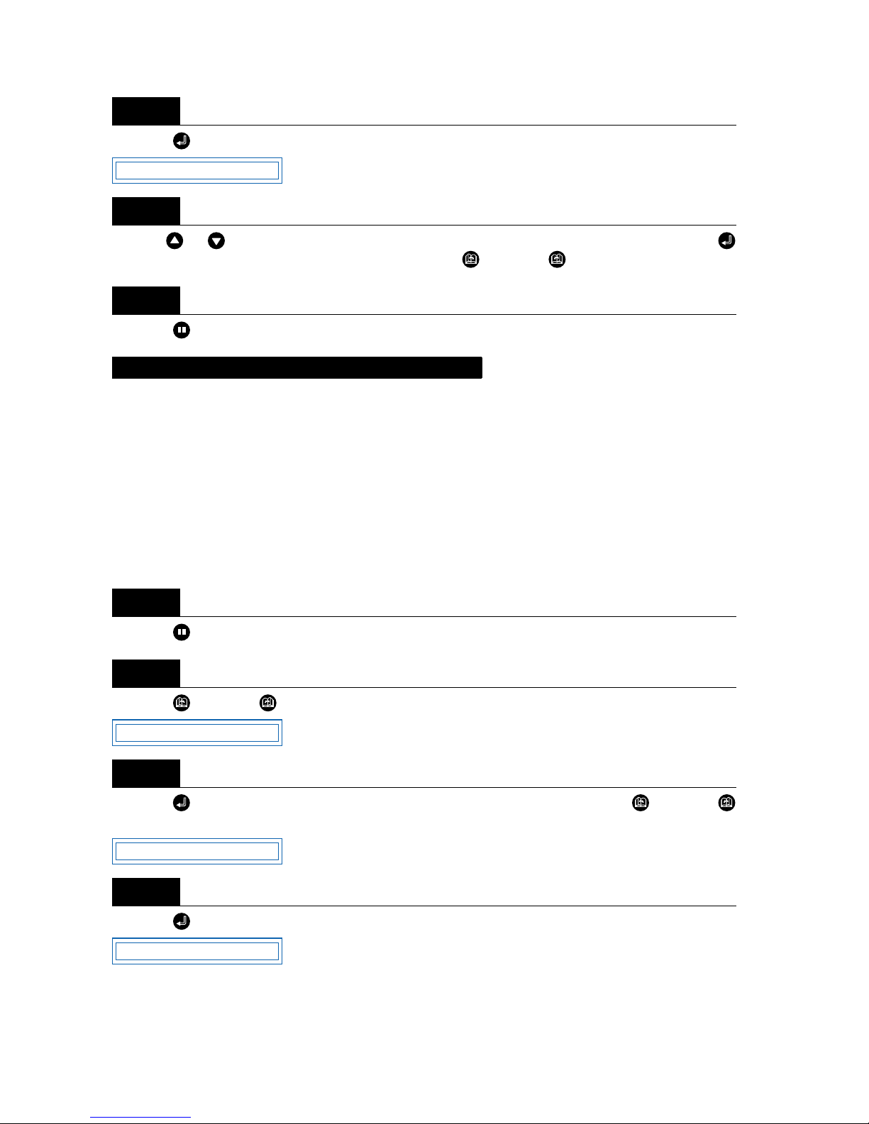
4 – 14
Press the (ENTER) key to display the registration-mark size setting.
Use the or key to set the value within the range “5 mm” to “20 mm,” and then press the
(ENTER) key to confirm. To cancel the selection, press the (NEXT) or (PREV.) key.
Press the (PAUSE) key to cancel PAUSE mode.
This adjusts the distance between registration marks automatically, rounding up or down to the nearest 5
mm, 10 mm, or 50 mm as specified. If STD. (Standard) is selected, the distance is automatically rounded
up or down to the nearest 5 mm, 10 mm, or 50 mm depending on the distance between the marks.
Up to 50 cm: 5 mm; 50 cm to 1 m: 10 mm; 1 m or larger: 50 mm. (Inch display: rounded up or down to the
nearest 0.25", 0.5", 0.75", 1", or 1.5").
For example, if the distance adjustment is set to 5 mm and the distance between the registration marks is
read as 312 mm, the distance is rounded down to the nearest 5 mm and is treated as a distance of 310
mm.
Press the (PAUSE) key to switch to PAUSE mode.
Press the (NEXT) or (PREV.) key until the following menu is displayed.
Press the (ENTER) key to display the Auto Reg. Mark submenu, and then press the (NEXT) or
(PREV.) key until the following menu is displayed.
Press the (ENTER) key to display the registration-mark distance-adjustment setting.
Step
4
Step
5
Step
6
Setting the Registration-mark Distance Adjustment
Step
1
Step
2
Step
3
Step
4
MARK SIZE 10mm
AUTO REG. MARK
MARK DIST. ADJ.
MARK DIST. OFF
Page 57
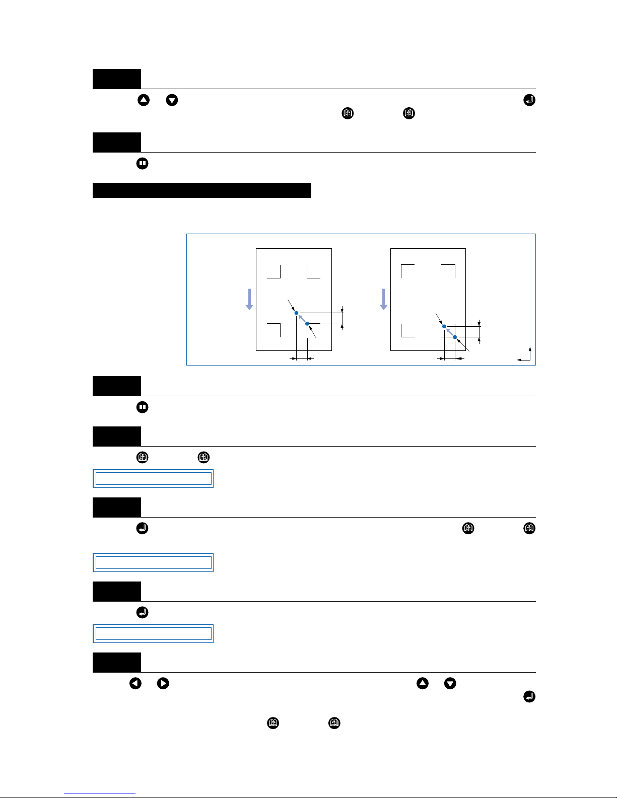
4 – 15
Press the or key to select “OFF,” “5 mm,” “10 mm,” “50 mm,” or “STD.” and then press the
(ENTER) key to confirm. To cancel the selection, press the (NEXT) or (PREV.) key.
Press the (PAUSE) key to cancel PAUSE mode.
If the registration-mark origin point is not set, it will be positioned as shown in the figures below. This function should be set when it is required to move the origin point from this position.
Press the (PAUSE) key to switch to PAUSE mode.
Press the (NEXT) or (PREV.) key until the following menu is displayed.
Press the (ENTER) key to display the Auto Reg. Mark submenu, and then press the (NEXT) or
(PREV.) key until the following menu is displayed.
Press the (ENTER) key to display the X-axis registration-mark origin input setting.
Use the or key to move the cursor to the digit to be entered, use the or key to increase or
decrease the values (or display/don’t display “-” for the space to the right of “=”), and then press the
(ENTER) key to confirm. The Y-axis origin input setting is then displayed and should be set in the same
way. To cancel the selection(s), press the (NEXT) or (PREV.) key.
Step
5
Step
6
Setting the Registration-mark Origin Point
Step
1
Step
2
Step
3
Step
4
Step
5
Registration-mark pattern 1
Medium feed direction
Registration-mark pattern 2
Origin
New origin
position
Origin
X
Y
New origin
position
X
Y
X
Y
AUTO REG. MARK
MARK OFFSET
OFST X= 000.0
Page 58
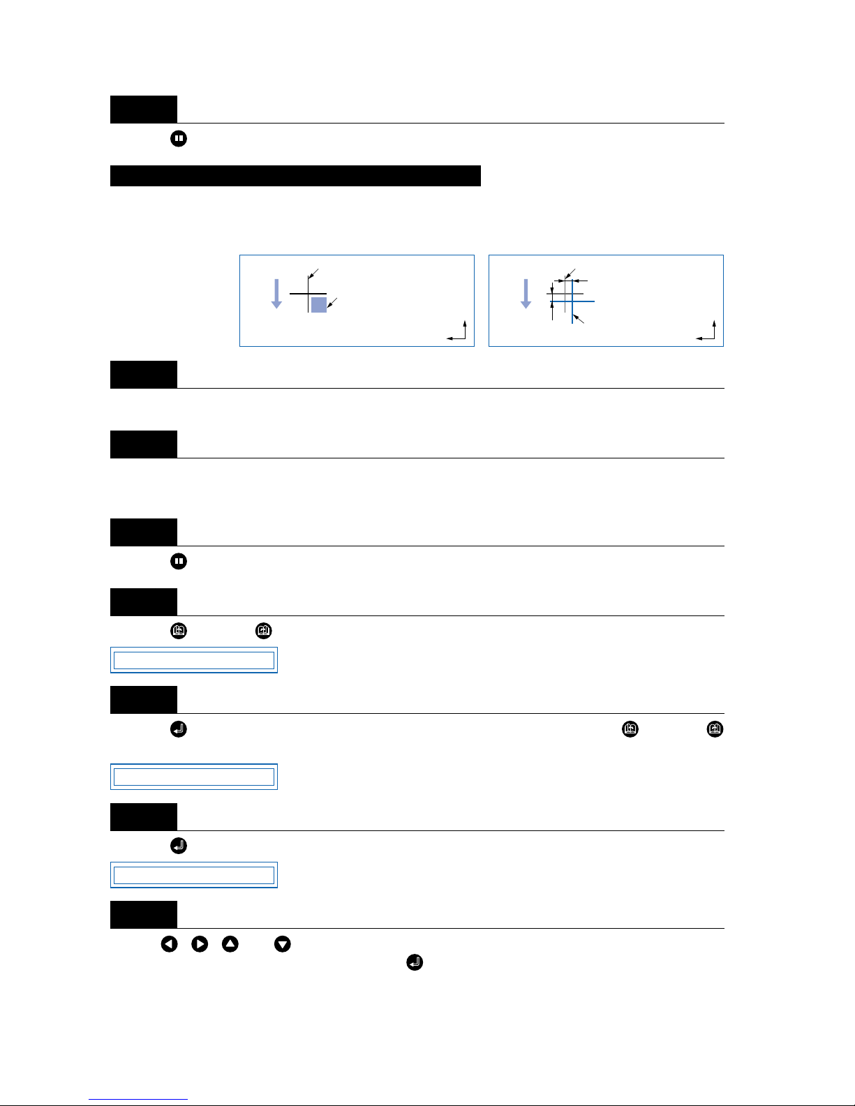
4 – 16
Press the (PAUSE) key to cancel PAUSE mode.
This adjusts the position of the sensor for the reading of registration marks. The adjustment crosshairs are
plotted after crosshairs already plotted have been read, and the difference between the two is input to
adjust the position.
Load a medium with the crosshairs plotted.
Set the cutter pen conditions to “PEN” (refer to “3.3 Setting the Cutter-Pen Conditions”), and mount a pen
in the cutting plotter.
Press the (PAUSE) key to switch to PAUSE mode.
Press the (NEXT) or (PREV.) key until the following menu is displayed.
Press the (ENTER) key to display the Auto Reg. Mark submenu, and then press the (NEXT) or
(PREV.) key until the following menu is displayed.
Press the (ENTER) key. The following menu is displayed.
Use the , , , and (POSITION) keys to move the cutter pen to the position of the crosshairs
already plotted on the medium, and then press the (ENTER) key. The sensor scans the crosshairs and
overwrites them.
Step
6
Adjusting the Registration-mark Reading Sensor (1)
Step
1
Step
2
Step
3
Step
4
Step
5
Step
6
Step
7
Medium feed
direction
Move the pen
within this area
Medium feed
direction
Crosshairs already
plotted
Newly plotted crosshairs
Crosshairs already plotted
Distance adjustment Y
Distance
adjustment X
X
Y
X
Y
AUTO REG. MARK
MARK SENSOR ADJ1
MARK ADJ1 SCAN
Page 59
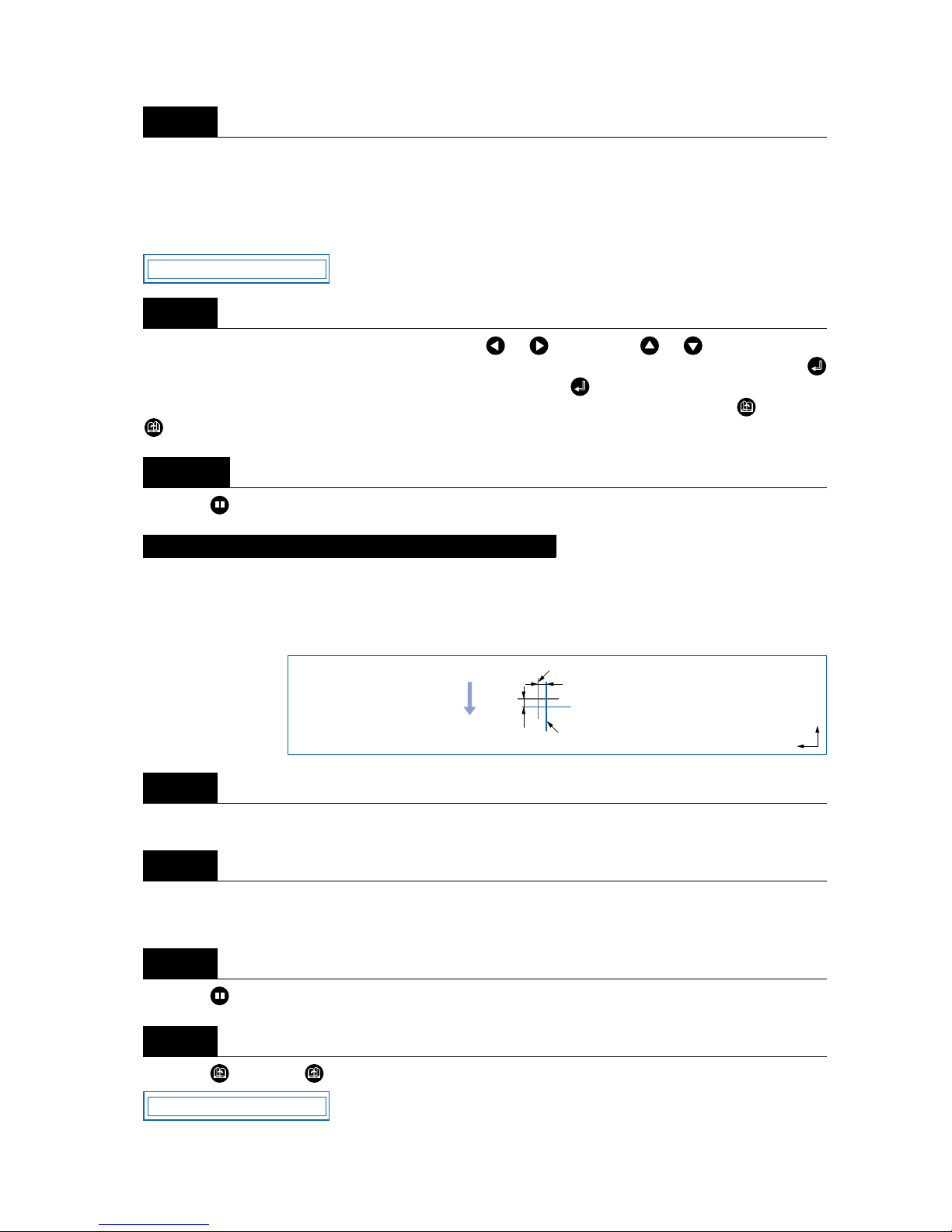
4 – 17
Measure the offset of the crosshairs in the X-axis, and enter the distance adjustment. Using the already
plotted crosshairs as the point of reference, enter the actual amount of the offset between these crosshairs
and the crosshairs that were plotted on top of them after the already plotted crosshairs were read by the
sensor. (For example, for the figure at the above right, since there is an offset in both the –X and –Y directions, enter the [X= –**mm] and [Y= –**mm] corrective values.)
Move the cursor to the digit to be entered using the or key, use the or key to increase or
decrease the values (or display/don’t display “-” for the space to the right of “=”), and then press the
(ENTER) key to confirm. If there is no offset, simply press the (ENTER) key. The Y-axis distanceadjustment input is then displayed and should be set in the same way. To cancel, press the (NEXT) or
(PREV.) key.
Press the (PAUSE) key to cancel PAUSE mode.
This adjusts the position of the sensor for reading the registration marks by plotting crosshairs and then
reading them. First set both cutter pen conditions 1 and 2 to the same pen. Crosshairs are first plotted
using conditions 1 and read by the sensor. A second set of adjustment crosshairs is plotted using conditions 2. The difference between the two is input to adjust the position.
Load a medium into the cutting plotter.
Set both cutter pen conditions 1 and 2 to the same “Pen” (refer to “3.3 Setting the Cutter-Pen Conditions”),
and load a pen in the cutting plotter.
Press the (PAUSE) key to switch to PAUSE mode.
Press the (NEXT) or (PREV.) key until the following menu is displayed.
Step
8
Step
9
Step
10
Adjusting the Registration-mark Reading Sensor (2)
Step
1
Step
2
Step
3
Step
4
ADJ X= 0.0
Medium feed
direction
Crosshairs first plotted
Adjustment crosshairs
Distance adjustment Y
Distance
adjustment X
X
Y
AUTO REG. MARK
Page 60
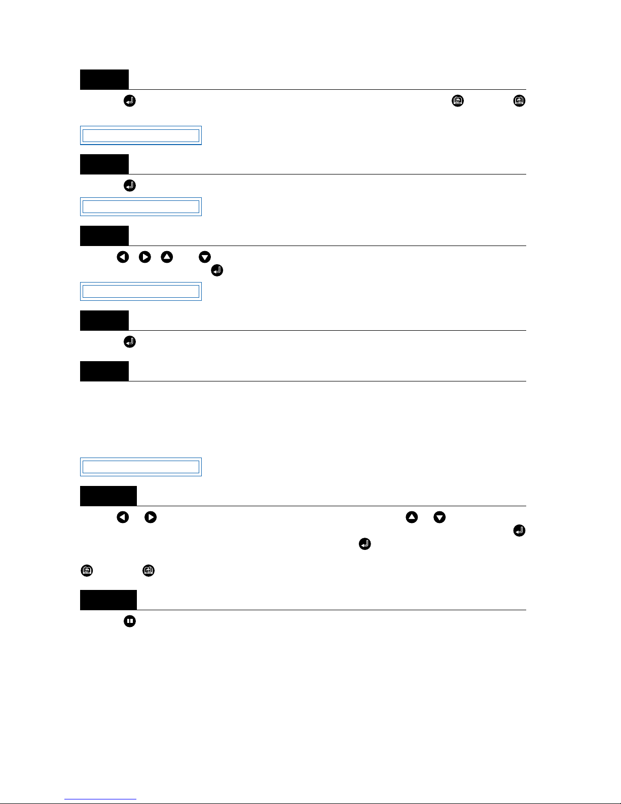
4 – 18
Press the (ENTER) key to display the Auto Reg. Mark submenu, and then press the (NEXT) or
(PREV.) key until the following menu is displayed.
Press the (ENTER) key. The following menu is displayed.
Use the , , , and (POSITION) keys to move the cutter pen to the position for plotting of the
crosshairs, and then press the (ENTER) key. The crosshairs are plotted and the following is displayed.
Press the (ENTER) key. The sensor scans the crosshairs and overwrites them.
Measure the offset of the crosshairs in the X-axis, and enter the distance adjustment. Using the crosshairs
that were plotted first as the point of reference, enter the actual amount of the offset between these
crosshairs and the adjustment crosshairs that were plotted after the first crosshairs were read by the sensor. (For example, for the figure shown above, since there is an offset in both the –X and –Y directions,
enter the [X= –**mm] and [Y= –**mm] corrective values.)
Use the or key to move the cursor to the digit to be entered, use the or key to increase or
decrease the values (or display/don’t display “-” for the space to the right of “=”), and then press the
(ENTER) key to confirm. If there is no offset, simply press the (ENTER) key. The Y-axis distanceadjustment input is then displayed and should be set in the same way. To cancel the selection(s), press the
(NEXT) or (PREV.) key.
Press the (PAUSE) key to cancel PAUSE mode.
Step
5
Step
6
Step
7
Step
8
Step
9
Step
10
Step
11
MARK SENSOR ADJ2
MARK ADJ2 SCAN
PRESS ENTER KEY
ADJ X= 0.0
Page 61
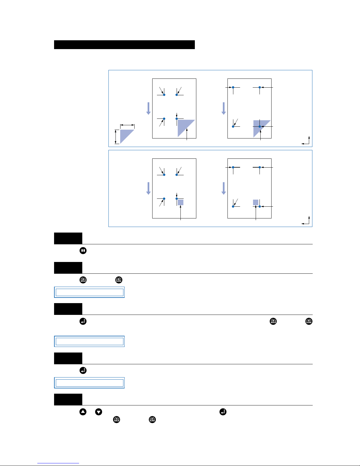
4 – 19
If the registration marks are at pre-determined positions on the medium, they can be scanned automatically.
Press the (PAUSE) key to switch to PAUSE mode.
Press the (NEXT) or (PREV.) key until the following menu is displayed.
Press the (ENTER) key to display the Auto Reg. Mark submenu, and then press the (NEXT) or
(PREV.) key until the following menu is displayed.
Press the (ENTER) key to display the Auto-scan mode setting.
Press the or key to select “ON” or “OFF,” and then press the (ENTER) key to confirm. T o cancel
the selection, press the (NEXT) or (PREV.) key.
Setting the Registration-mark Auto-scan mode
Step
1
Step
2
Step
3
Step
4
Step
5
Registration-mark pattern 1
Medium feed direction
Registration-mark pattern 2
Move the pen tip within this area
Point 2Point 4
Point 1
(the desired
Origin Point)
Point 2
Point 4
Point 3
Point 1
(the desired Origin Point)
Point 3
Move the pen tip within this area
X
Y
When ON
was selected
100mm
100mm
Registration-mark pattern 1
Medium feed direction
Point 2Point 4
Registration-mark pattern 2
Move the pen tip within this area
Point 1
(the desired
Origin Point)
Point 2Point 4
Point 3
Point 1
(the desired Origin Point)
Point 3
Move the pen tip within this area
X
Y
When OFF
was selected
AUTO REG. MARK
MARK AUTO SCAN
AUTO SCAN ON
Page 62

4 – 20
Press the (PAUSE) key to cancel PAUSE mode.
There may be instances when the registration-mark sensor does not function correctly, depending on how
it is moved. If this happens, adjusting the sensitivity will enable the sensor to perform detection correctly in
most cases.
Press the (PAUSE) key to switch to PAUSE mode.
Press the (NEXT) or (PREV.) key until the following menu is displayed.
Press the (ENTER) key to display the Auto Reg. Mark submenu, and then press the (NEXT) or
(PREV.) key until the following menu is displayed.
Press the (ENTER) key to display the Mark Sensor sensitivity setting.
Use the or key to increase or decrease the setting within the range of “-5” to “5,” and then press the
(ENTER) key to confirm. A positive value increases the sensitivity, but makes the cutting plotter more
susceptible to other influences and less able to withstand noise. A negative value decreases the sensitivity,
but makes the cutting plotter less susceptible to other influences and more able to withstand noise. T o cancel the selection, press the (NEXT) or (PREV.) key.
Press the (PAUSE) key to cancel PAUSE mode.
Step
6
Adjusting the Sensitivity of the Registration-Mark Sensor
Step
1
Step
2
Step
3
Step
4
Step
5
Step
6
AUTO REG. MARK
MARK SENSOR ADJ
MARK SENSOR 0
Page 63
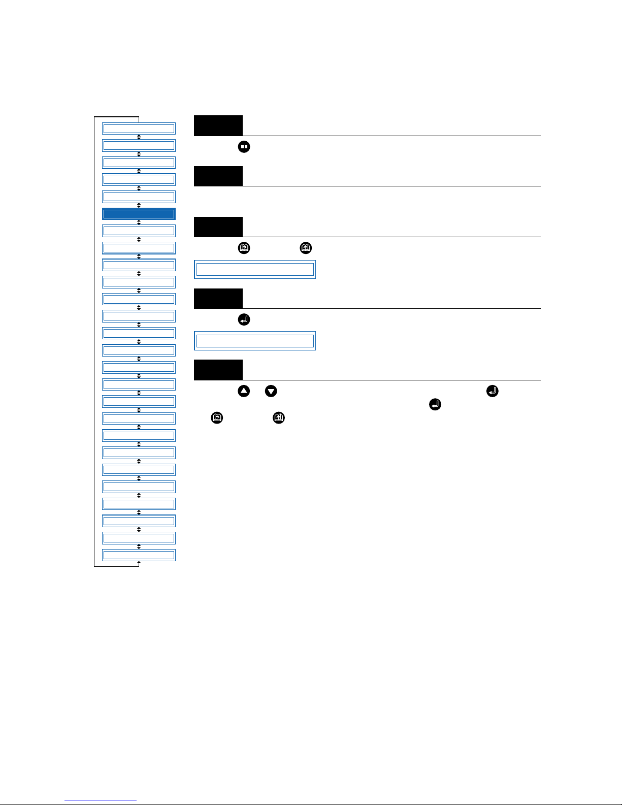
4 – 21
4.7 Clearing the Buffer Memory
This function deletes the data sent to the cutting plotter. It is used to abort cutting while it is in progress.
Press the (PAUSE) key to switch to PAUSE mode.
Stop the transmission of data from the computer if this is in progress.
Press the (NEXT) or (PREV.) key until the following menu is displayed.
Press the (ENTER) key to display the clear-buffer-memory menu.
Press the or key to select “YES” or “NO,” and then press the (ENTER)
key. To cancel the selection, select “NO” and press the (ENTER) key, or press
the (NEXT) or (PREV.) key.
Step
1
Step
2
Step
3
Step
4
Step
5
FEED
MOVE TO R. MARK
AUTO PRE FEED
TANGENTIAL
AUTO REG. MARK
CLEAR BUFFER
AXIS ALIGNMENT
DISTANCE ADJUST
PAGE LENGTH
PLOT AREA
EXPAND
ROTATE
MIRROR
COPY
SORT
RS-232C
COMMAND
BLADE WEAR SETUP
PEN UP/DOWN
TEST MODE
PEN UP SPEED
OFFSET FORCE
OFFSET ANGLE
STEP PASS
INIT. DOWN FORCE
LENGTH UNIT
*
*
*: Option
CLEAR BUFFER
CLEAR <YES>
Page 64
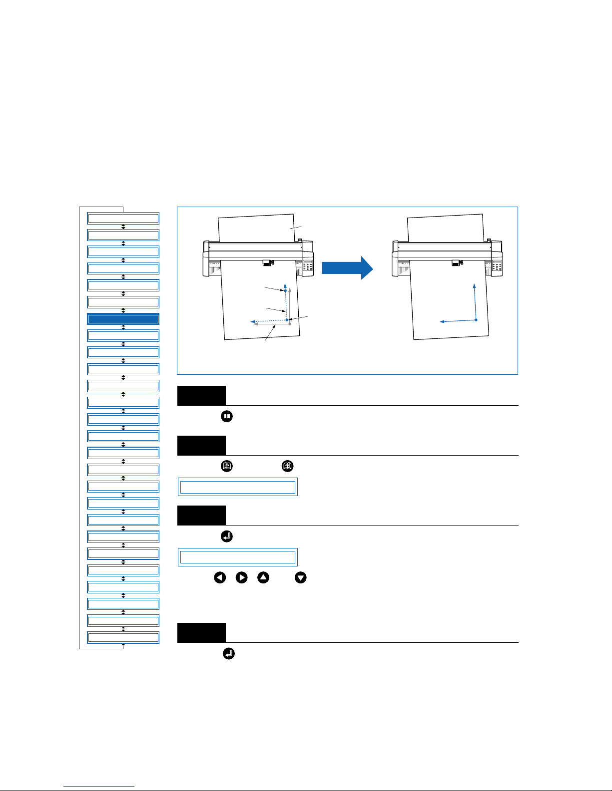
4 – 22
4.8 Aligning the Coordinate Axes
This function is used to compensate for any offset in the origin or angular deviation in the coordinate axes
that occurs when a medium plotted in another plotter is loaded or when a previously plotted medium is
reloaded. This function enables the cutting of outlines plotted using a different plotter, or drawings previously plotted to be recut. Plotting the origin and X-axis line bef ore the coordinate axes are aligned makes it
easier to adjust the axes. Plot the origin and X-axis line within the plotting area to enable settings to be
specified even if the X-axis and origin are positioned at an angle. If the origin and X-axis line are plotted
near the boundaries of the plotting area, the settings may lie outside the plotting area, making it impossible
to align the axes.
Press the (PAUSE) key to switch to PAUSE mode.
Press the (NEXT) or (PREV.) key until the following menu is displayed.
Press the (ENTER) key to display the axis-alignment menu.
Use the , , , and (POSITION) keys to move the cutter pen to alignment point 1 (the origin on the previously plotted medium). The coordinates displayed here indicate the distance from the current origin point.
Press the (ENTER) key to set the new origin, and use this as the center of
rotation for the X-axis.
Step
1
Step
2
Step
3
Step
4
FEED
MOVE TO R. MARK
AUTO PRE FEED
TANGENTIAL
AUTO REG. MARK
CLEAR BUFFER
AXIS ALIGNMENT
DISTANCE ADJUST
PAGE LENGTH
PLOT AREA
EXPAND
ROTATE
MIRROR
COPY
SORT
RS-232C
COMMAND
BLADE WEAR SETUP
PEN UP/DOWN
TEST MODE
PEN UP SPEED
OFFSET FORCE
OFFSET ANGLE
STEP PASS
INIT. DOWN FORCE
LENGTH UNIT
*
*
*: Option
Offset between plotted medium and
cutting-plotter X/Y-axis and origin
X/Y-axis and origin offset corrected
Axis alignment
Origin
X
Y
Alignment point 1
(Origin on previously
plotted medium)
Cutting-plotter reference point
Reloaded medium
already plotted
Alignment
point 2
Drawing
reference
points
New origin
X
Y
AXIS ALIGNMENT
PT1 0, 0
Page 65

4 – 23
Use the , , , and (POSITION) keys to move the cutter pen to alignment point 2 (an y point on
the X-axis for the previously plotted medium). The coordinates displayed here indicate the distance from
alignment point 1.
Press the (ENTER) key to calculate the X-axis angle of inclination and align the axes.
Press the (PAUSE) key to cancel PAUSE mode.
Step
5
Step
6
Step
7
After the axes are aligned, the settings will be reset if any of the following are performed.
• Specification of a new origin
• Loading of a new medium
• Setting of the axis rotation
PT2 0, 0
CHECKPOINT
Page 66
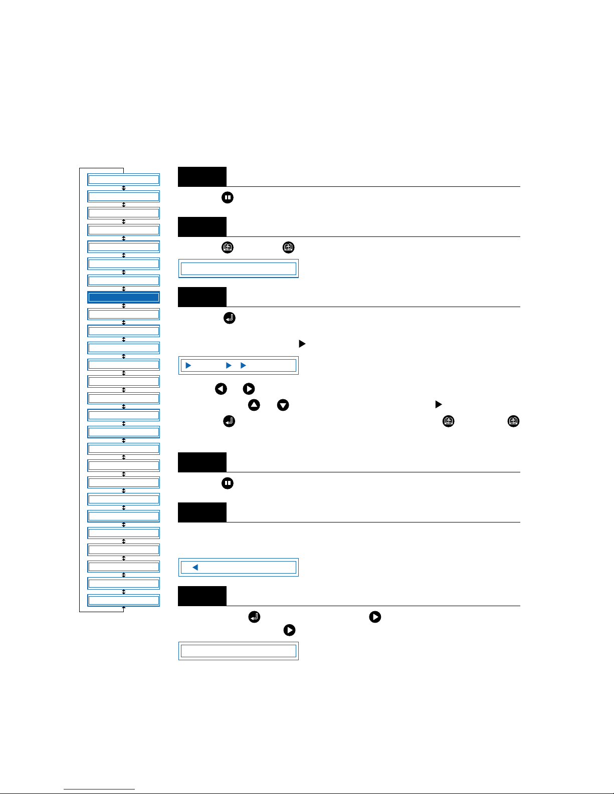
4 – 24
4.9 Distance Adjustment
This function corrects any deviation in the length of cut or the plotted line segments, which occurs depending on the medium being used. The adjustment value for the deviation is specified as a percentage of the
total distance. For example, a setting of 0.05% adjusts a distance of 2 m (2,000 mm) by +1 mm (2000 x
0.05% = 1 mm), to become 2,001 mm. Eight different cutter-pen condition-setting areas can be set on or
off separately, allowing different settings to be made in order to suit the medium used.
Press the (PAUSE) key to switch to PAUSE mode.
Press the (NEXT) or (PREV.) key until the following menu is displayed.
Press the (ENTER) key to display the distance adjustment menu. The numbers “1” to “8” indicate the cutter-pen condition-setting areas, and those that are
set on are indicated with the symbol to the left.
Use the or key to move the cursor to select the required condition-setting
area. Press the or key to display or not display the symbol, and then
press the (ENTER) key to confirm. To cancel, press the (NEXT) or
(PREV.) key.
Press the (PAUSE) key to cancel PAUSE mode.
Select the condition-setting area to be set to “ON” (refer to “Selecting Cutter-Pen-
Condition Setting Areas” on page 3-6).
Either press the (ENTER) key or use the key to move the cursor to the far
right, and then press the key to display the following menu.
Step
1
Step
2
Step
3
Step
4
Step
5
Step
6
FEED
MOVE TO R. MARK
AUTO PRE FEED
TANGENTIAL
AUTO REG. MARK
CLEAR BUFFER
AXIS ALIGNMENT
DISTANCE ADJUST
PAGE LENGTH
PLOT AREA
EXPAND
ROTATE
MIRROR
COPY
SORT
RS-232C
COMMAND
BLADE WEAR SETUP
PEN UP/DOWN
TEST MODE
PEN UP SPEED
OFFSET FORCE
OFFSET ANGLE
STEP PASS
INIT. DOWN FORCE
LENGTH UNIT
*
*
*: Option
DISTANCE ADJUST
1 2 3 4 5 6 7 8
5 15U 0 20 30 1
X= 0.00%Y= 0.00%
Page 67

4 – 25
Select “X” or “Y” using the or key. Use the or key to increase or decrease the setting within
the range of “-2.00%” to “+2.00%,” and then press the (ENTER) key to confirm. If the condition-setting
area is set for TANGENTIAL mode, the TANGENTIAL-mode setting will be displayed. Press (ENTER)
again. To cancel the selection(s), press the (NEXT) or (PREV.) key.
Step
7
This setting is retained in the memory even when the power is turned off.
CHECKPOINT
Page 68
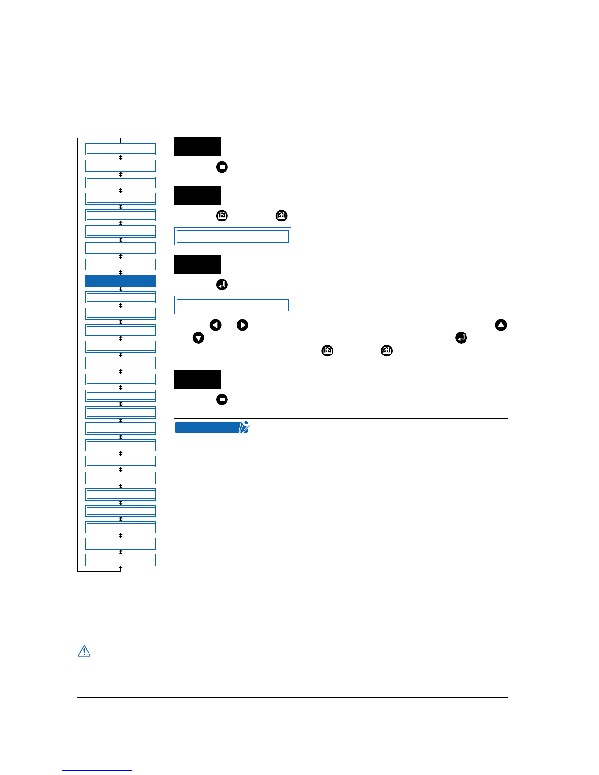
4 – 26
4.10 Setting the PAGE LENGTH
This function sets the length of each page when long-axis cutting or plotting is performed using a roll
medium. This should be set for long-axis cutting or plotting exceeding 5 m in length. The default setting is
“5000 mm.“
Press the (PAUSE) key to switch to PAUSE mode.
Press the (NEXT) or (PREV.) key until the following menu is displayed.
Press the (ENTER) key to display the page-length menu.
Use the or key to move the cursor to the digit to be changed. Use the
and keys to increase or decrease the setting, and then press the (ENTER)
key to confirm. To cancel, press the (NEXT) or (PREV.) key.
Press the (PAUSE) key to cancel PAUSE mode.
Step
1
Step
2
Step
3
Step
4
• This setting is retained in the memory even when the
power is turned off.
• The cutting plotter’s distance precision is guaranteed for
page-feed lengths of up to 5 meters, provided that the
following conditions are satisfied (CE3000-60/120).
Long-axis cutting over 5 meters is possible for lengths of
up to 50 meters in the feeding direction.
Guaranteed precision conditions:
–The cutting plotter is mounted on its stand.
–Graphtec-specified film is used with the stipulated set-
ting conditions.
Film: 3M plastic-backed film
Setting conditions: Cutter speed, 30 cm/s max; Quality, 1
• In the case of long-axis cutting, be particularly careful
when loading color adhesive-backed film. If the film is
loaded at even a slight angle, the film may come loose
from the rollers that hold it in place.
When using roll media, either extend and load the length to be used beforehand or use the
media feed procedure (“4.3 Setting the FEED function”, “4.4 Setting AUTO PRE-FEED”).
Beginning cutting or plotting without feeding the media first may generate a position error
or may cause the roll media to fall off the stoc k shaft.
FEED
MOVE TO R. MARK
AUTO PRE FEED
TANGENTIAL
AUTO REG. MARK
CLEAR BUFFER
AXIS ALIGNMENT
DISTANCE ADJUST
PAGE LENGTH
PLOT AREA
EXPAND
ROTATE
MIRROR
COPY
SORT
RS-232C
COMMAND
BLADE WEAR SETUP
PEN UP/DOWN
TEST MODE
PEN UP SPEED
OFFSET FORCE
OFFSET ANGLE
STEP PASS
INIT. DOWN FORCE
LENGTH UNIT
*
*
*: Option
PAGE LENGTH
L=05000mm
CHECKPOINT
CAUTION
Page 69
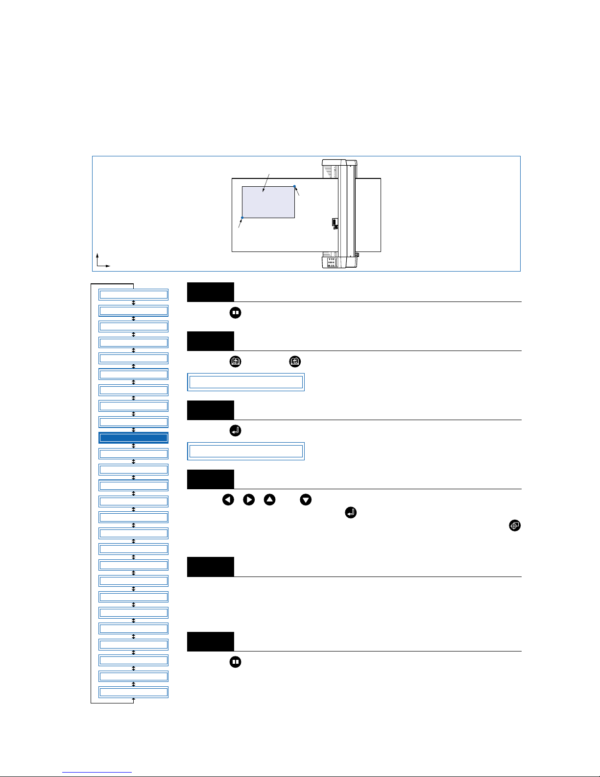
4 – 27
4.11 Setting the Cutting/Plotting Area
This function allows the area in which cutting/plotting will be performed to be specified, thereby preventing
cutting/plotting outside the specified area. This function enables more efficient use of the film through the
specification of uncut portions of a film that have already been cut, to avoid the previously cut areas. Note
that setting of the cutting/plotting area also repositions the origin point in accordance with the movement of
the cutting area.
Press the (PAUSE) key to switch to PAUSE mode.
Press the (NEXT) or (PREV.) key until the following menu is displayed.
Press the (ENTER) key to display the plotting-area menu.
Use the , , , and (POSITION) keys to move the pen to the lower-left
setting position, and then press the (ENTER) key. The coordinates of the
lower-left position set are displayed. To make the default setting, press the
(ORIGIN) key.
Once the lower-left position has been set, the coordinates for the upper-right position are displayed. Set these coordinates in the same way as for the lower-left position.
Press the (PAUSE) key to cancel PAUSE mode.
Step
1
Step
2
Step
3
Step
4
Step
5
Step
6
Lower-left setting position
Upper-right
setting
position
Cutting/plotting in this area only
Y
X
FEED
MOVE TO R. MARK
AUTO PRE FEED
TANGENTIAL
AUTO REG. MARK
CLEAR BUFFER
AXIS ALIGNMENT
DISTANCE ADJUST
PAGE LENGTH
PLOT AREA
EXPAND
ROTATE
MIRROR
COPY
SORT
RS-232C
COMMAND
BLADE WEAR SETUP
PEN UP/DOWN
TEST MODE
PEN UP SPEED
OFFSET FORCE
OFFSET ANGLE
STEP PASS
INIT. DOWN FORCE
LENGTH UNIT
*
*
*: Option
PLOT AREA
LL 0, 0
Page 70
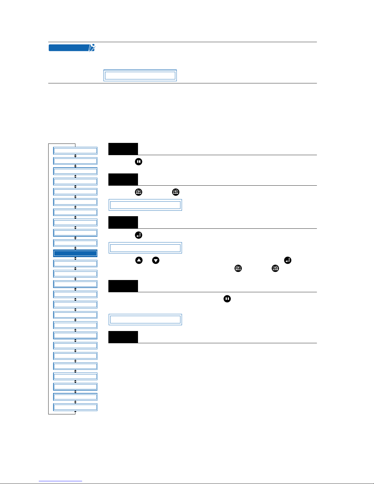
4 – 28
4.12 Expanding the Cutting/Plotting Area
This function allows the width of the cutting/plotting area to be extended by 9.5 mm on both sides, for a
total increase of 19 mm, enabling cutting to be performed up to the area in which the pinch rollers are positioned.
Press the (PAUSE) key to switch to PAUSE mode.
Press the (NEXT) or (PREV.) key until the following menu is displayed.
Press the (ENTER) key to display the plotting-area width-setting menu.
Press the or key to select “ON” or “OFF,” and then press the (ENTER)
key to confirm. To cancel the selection, press the (NEXT) or (PREV.) key.
If the settings are not changed, press the (PAUSE) key to cancel PAUSE
mode. If the settings are changed, the media-type selection menu is displayed.
For details on the media loading and selection procedures, refer to “2.3 Loading
the Medium.”
The following message is displa y ed if the lo wer-left and upper-right settings are not
separated by a distance of at least 5 mm. If this message appears, reset the lowerleft and upper-right positions.
Step
1
Step
2
Step
3
Step
4
Step
5
CHECKPOINT
WRONG PLOT AREA
FEED
MOVE TO R. MARK
AUTO PRE FEED
TANGENTIAL
AUTO REG. MARK
CLEAR BUFFER
AXIS ALIGNMENT
DISTANCE ADJUST
PAGE LENGTH
PLOT AREA
EXPAND
ROTATE
MIRROR
COPY
SORT
RS-232C
COMMAND
BLADE WEAR SETUP
PEN UP/DOWN
TEST MODE
PEN UP SPEED
OFFSET FORCE
OFFSET ANGLE
STEP PASS
INIT. DOWN FORCE
LENGTH UNIT
*
*
*: Option
EXPAND
EXPAND OFF
ROLL2 PRESS ENTR
Page 71
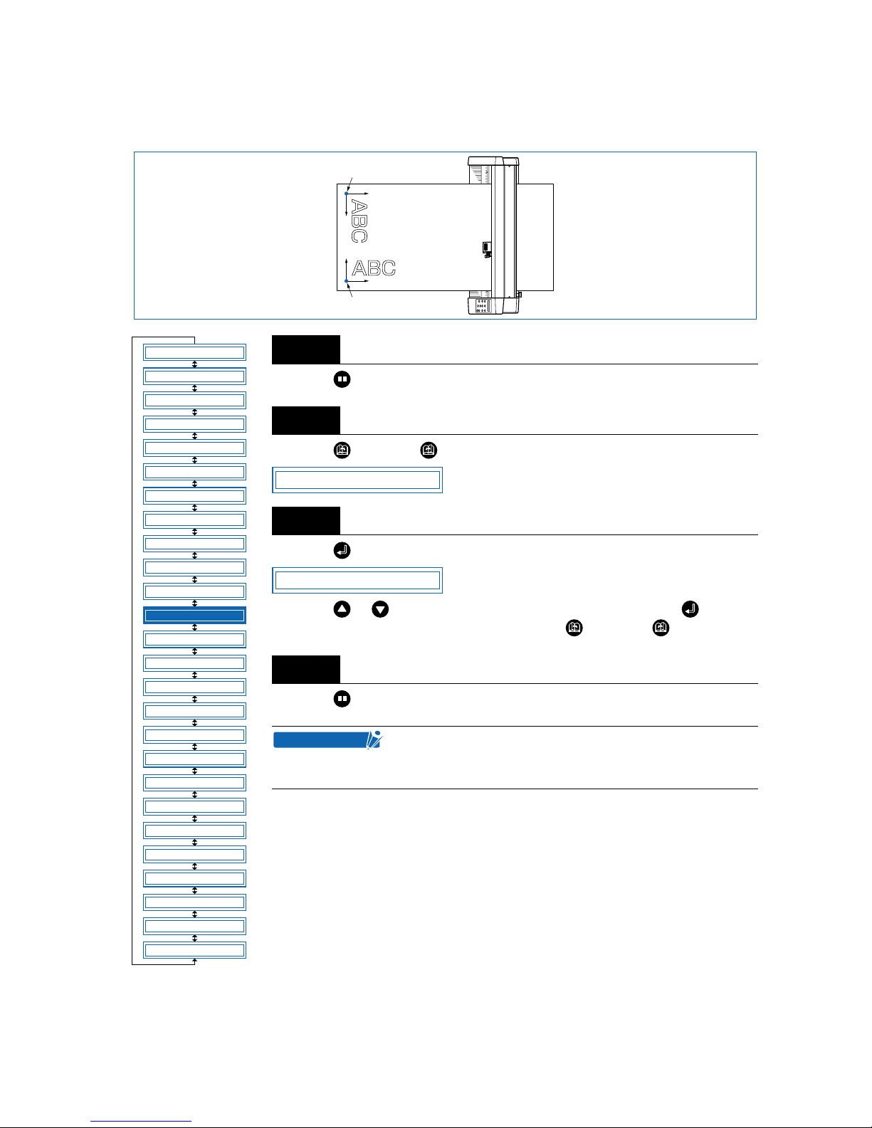
4 – 29
4.13 Rotating the Coordinate Axes
This function allows the cutting/plotting origin and coordinate axes to be rotated as shown below.
Press the (PAUSE) key to switch to PAUSE mode.
Press the (NEXT) or (PREV.) key until the following menu is displayed.
Press the (ENTER) key to display the coordinate-axis rotation-setting menu.
Press the or key to select “ON” or “OFF,” and then press the (ENTER)
key to confirm. To cancel the selection, press the (NEXT) or (PREV.) key.
Press the (PAUSE) key to cancel PAUSE mode.
Step
1
Step
2
Step
3
Step
4
This setting is retained in the memory even when the
power is turned off.
When ON is selected for ROTATE, MIRROR is set to OFF.
New origin
When axiscoordinate rotation
is “off”
When axis-coordinate
rotation is “on”
X
Y
Y
X
Origin
FEED
MOVE TO R. MARK
AUTO PRE FEED
TANGENTIAL
AUTO REG. MARK
CLEAR BUFFER
AXIS ALIGNMENT
DISTANCE ADJUST
PAGE LENGTH
PLOT AREA
EXPAND
ROTATE
MIRROR
COPY
SORT
RS-232C
COMMAND
BLADE WEAR SETUP
PEN UP/DOWN
TEST MODE
PEN UP SPEED
OFFSET FORCE
OFFSET ANGLE
STEP PASS
INIT. DOWN FORCE
LENGTH UNIT
*
*
*: Option
ROTATE
ROTATE OFF
CHECKPOINT
Page 72
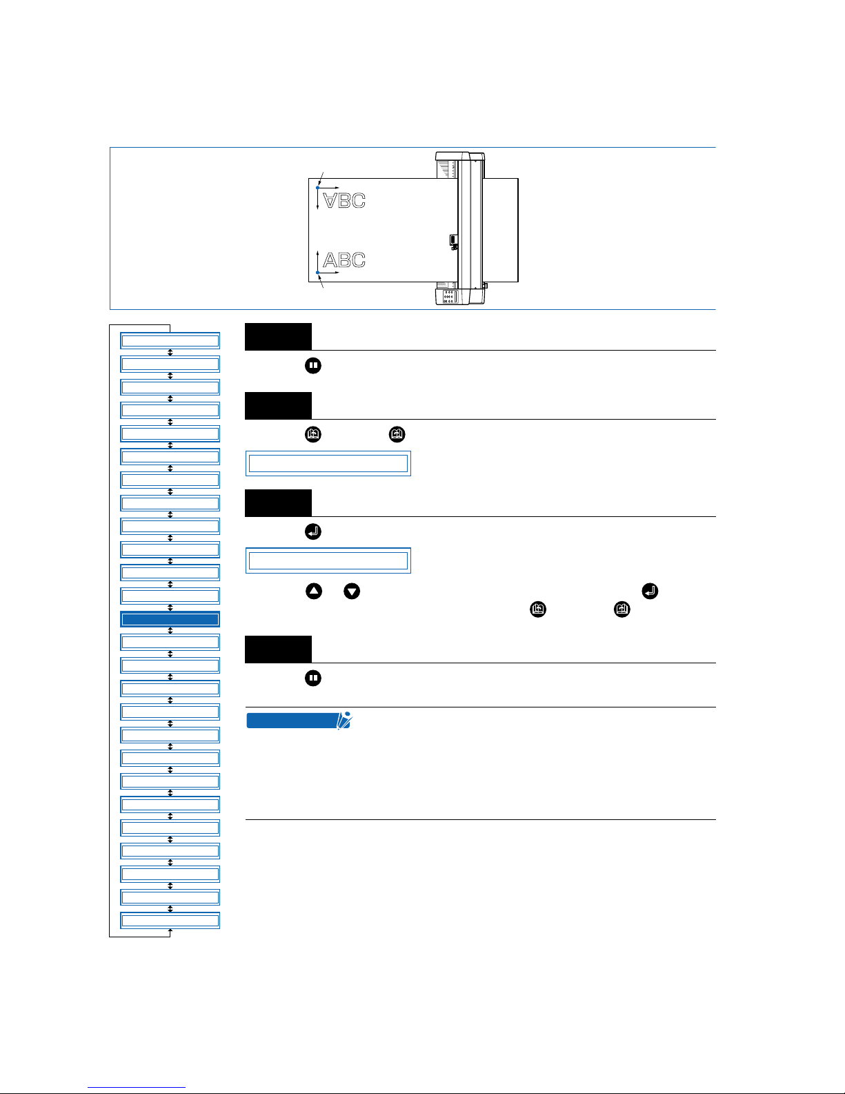
4 – 30
4.14 Mirroring
This function allows the cutting/plotting origin and coordinate axes to be changed, as shown below.
Press the (PAUSE) key to switch to PAUSE mode.
Press the (NEXT) or (PREV.) key until the following menu is displayed.
Press the (ENTER) key to display the Mirror setting.
Press the or key to select “ON” or “OFF,” and then press the (ENTER)
key to confirm. To cancel the selection, press the (NEXT) or (PREV.) key.
Press the (PAUSE) key to cancel PAUSE mode.
Step
1
Step
2
Step
3
Step
4
• This setting is retained in the memory even when the
power is turned off.
• When ON is selected for MIRROR, RO TATE (coordinateaxis rotation) is set to OFF.
• Auto mark reading cannot be performed when MIRROR
is set to ON.
The origin when MIRROR is “on”
X
Y
X
Y
The origin when MIRROR is “off”
FEED
MOVE TO R. MARK
AUTO PRE FEED
TANGENTIAL
AUTO REG. MARK
CLEAR BUFFER
AXIS ALIGNMENT
DISTANCE ADJUST
PAGE LENGTH
PLOT AREA
EXPAND
ROTATE
MIRROR
COPY
SORT
RS-232C
COMMAND
BLADE WEAR SETUP
PEN UP/DOWN
TEST MODE
PEN UP SPEED
OFFSET FORCE
OFFSET ANGLE
STEP PASS
INIT. DOWN FORCE
LENGTH UNIT
*
*
*: Option
MIRROR
MIRROR OFF
CHECKPOINT
Page 73
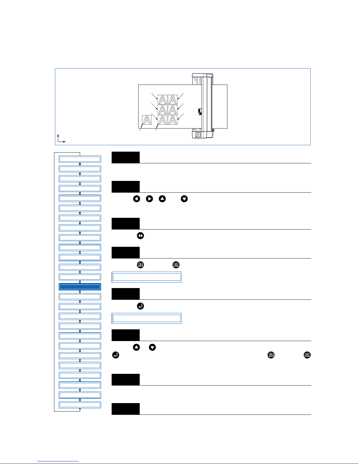
4 – 31
4.15 Cutting/Plotting Using the Buffer Memory (COPY Function)
This function is used to make duplicate copies of cutting or plotting data that has been sent from the computer and is retained in the cutting plotter’s internal memory.
Send the data to be copied to the cutting plotter, and cut or plot the data once.
Use the , , , and (POSITION) keys to move the pen to the starting
position for cutting or plotting.
Press the (PAUSE) key to switch to PAUSE mode.
Press the (NEXT) or (PREV.) key until the following menu is displayed.
Press the (ENTER) key to display the copy-setting menu.
Use the or key to select the desired number of copies, and then press the
(ENTER) key to confirm. To cancel the selection, press the (NEXT) or
(PREV.) key.
The cutting/plotting operation starts for the number of copies selected.
To make further copies, replace the medium and repeat steps 2 to 6.
Step
1
Step
2
Step
3
Step
4
Step
5
Step
6
Step
7
Step
8
Origin Copy origin
(Initial position for
plotting copy)
1st
copy
2nd
copy
3rd
copy
4th
copy
5th copy
6th copy
Y
X
FEED
MOVE TO R. MARK
AUTO PRE FEED
TANGENTIAL
AUTO REG. MARK
CLEAR BUFFER
AXIS ALIGNMENT
DISTANCE ADJUST
PAGE LENGTH
PLOT AREA
EXPAND
ROTATE
MIRROR
COPY
SORT
RS-232C
COMMAND
BLADE WEAR SETUP
PEN UP/DOWN
TEST MODE
PEN UP SPEED
OFFSET FORCE
OFFSET ANGLE
STEP PASS
INIT. DOWN FORCE
LENGTH UNIT
*
*
*: Option
COPY
COPY COUNT 1
Page 74

4 – 32
If the data to be copied does not fit within the cutting/plotting area, the following message is displayed in
step 5.
Use the , , , and (POSITION) keys to change the initial copying position or load a medium
with an area of sufficient size to fit the copied data.
• If the initial cutting/plotting position was moved from the original origin, the new
origin will also apply during the copying operation. To prevent wasteful use of the
medium, the initial cutting/plotting position for the data should be as close as
possible to the origin.
• If the cutting plotter receives another set of data during the copying operation,
the operation will not be properly completed because the initial data is cleared
during the operation. Do not send new data to the cutting plotter while copying is
in progress.
• If new data is sent to the cutting plotter more than 10 seconds after the initial cutting data is sent, the original data will be cleared from the internal memory.
• Copying will not be possible if data exceeding 2 Mbytes is sent to the cutting plotter, as the data will cause the buffer memory to overflow.
CANNOT COPY
CHECKPOINT
Page 75
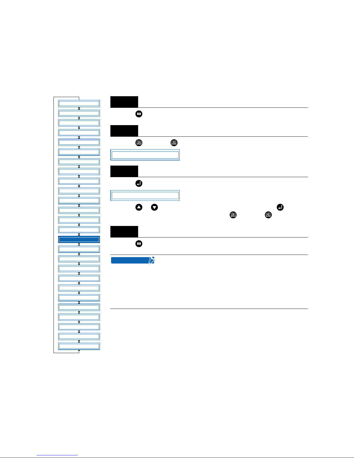
4 – 33
4.16 Sorting Settings
This function sorts and cuts or plots the cutting/plotting data stored in the buffer memory to minimize the
amount of medium feed required. This is useful for data requiring a large number of movements on the
drawing with the pen raised. If the data received has been sor ted using the application software, sorting
the data using the cutting plotter may require additional time. Turning this function off may speed up the
process.
Press the (PAUSE) key to switch to PAUSE mode.
Press the (NEXT) or (PREV.) key until the following menu is displayed.
Press the (ENTER) key to display the sorting setting menu.
Press the or key to select “ON” or “OFF,” and then press the (ENTER)
key to confirm. To cancel the selection, press the (NEXT) or (PREV.) key.
Press the (PAUSE) key to cancel PAUSE mode.
Step
1
Step
2
Step
3
Step
4
• This setting is retained in the memory even when the
power is turned off.
• If data for which the cutting/plotting sequence has been
set using the application software is received, the cutting/plotting sequence may be changed if this function is
set to “ON.” The function should be set to “OFF” in this
case.
FEED
MOVE TO R. MARK
AUTO PRE FEED
TANGENTIAL
AUTO REG. MARK
CLEAR BUFFER
AXIS ALIGNMENT
DISTANCE ADJUST
PAGE LENGTH
PLOT AREA
EXPAND
ROTATE
MIRROR
COPY
SORT
RS-232C
COMMAND
BLADE WEAR SETUP
PEN UP/DOWN
TEST MODE
PEN UP SPEED
OFFSET FORCE
OFFSET ANGLE
STEP PASS
INIT. DOWN FORCE
LENGTH UNIT
*
*
*: Option
SORT
SORT OFF
CHECKPOINT
Page 76
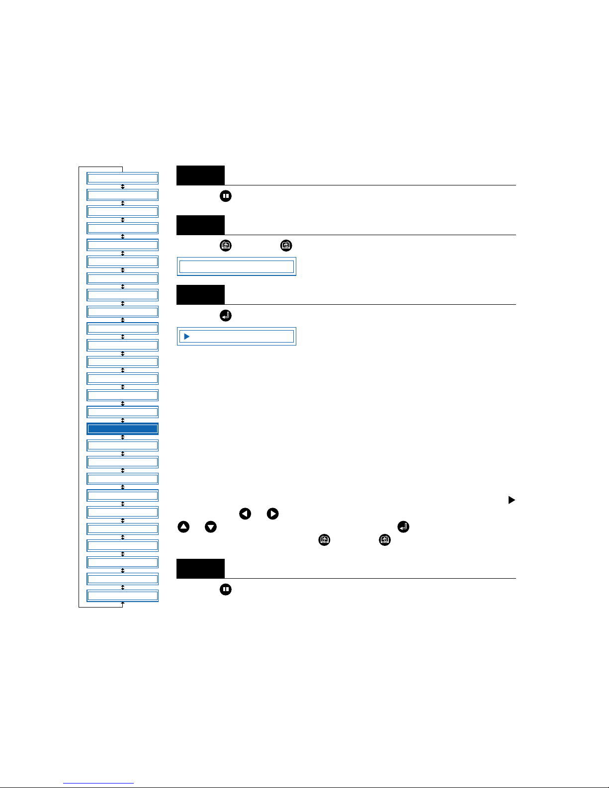
4 – 34
4.17 Interface Settings
The interface conditions must be set if the RS-232C serial interface is used, to ensure that the data-transfer rate (baud rate), data length, and parity settings for the cutting plotter match those set in the application
software or computer operating system. This section describes the interface conditions for the cutting plotter. For details on how to set the conditions for your application or computer operation system, refer to the
manual provided with the application or operating system.
Press the (PAUSE) key to switch to PAUSE mode.
Press the (NEXT) or (PREV.) key until the following menu is displayed.
Press the (ENTER) key to display the interface-condition setting menu.
The current settings are displayed (from left): transfer rate (baud rate), parity, data
length, and handshaking mode.
The baud rate can be set to “19200,” “9600,” “4800,” “2400,” “1200,” “600,” or
“300.”
The parity can be set to “N” (None), “E” (Even parity), or “O” (Odd parity).
The data length can be set to 7 or 8 bits.
The handshaking mode can be set to “H” (hard-wired handshaking) or “X” (Xon/
Xoff handshaking). “E” (ENQ/ACK handshaking) can also be selected when the
command mode is set to HP-GL.
All of these interface conditions must be set to match the corresponding settings in
the application software and the computer operating system.
The parameter that can be changed is displayed immediately to the right of the
mark. Use the or key to select the parameter to be changed, and use the
or key to select the setting details. Press the (ENTER) key to confirm.
To cancel the selection, press the (NEXT) or (PREV.) key.
Press the (PAUSE) key to cancel PAUSE mode.
Step
1
Step
2
Step
3
Step
4
FEED
MOVE TO R. MARK
AUTO PRE FEED
TANGENTIAL
AUTO REG. MARK
CLEAR BUFFER
AXIS ALIGNMENT
DISTANCE ADJUST
PAGE LENGTH
PLOT AREA
EXPAND
ROTATE
MIRROR
COPY
SORT
RS-232C
COMMAND
BLADE WEAR SETUP
PEN UP/DOWN
TEST MODE
PEN UP SPEED
OFFSET FORCE
OFFSET ANGLE
STEP PASS
INIT. DOWN FORCE
LENGTH UNIT
*
*
*: Option
RS-232C
9600 N 8 H
Page 77
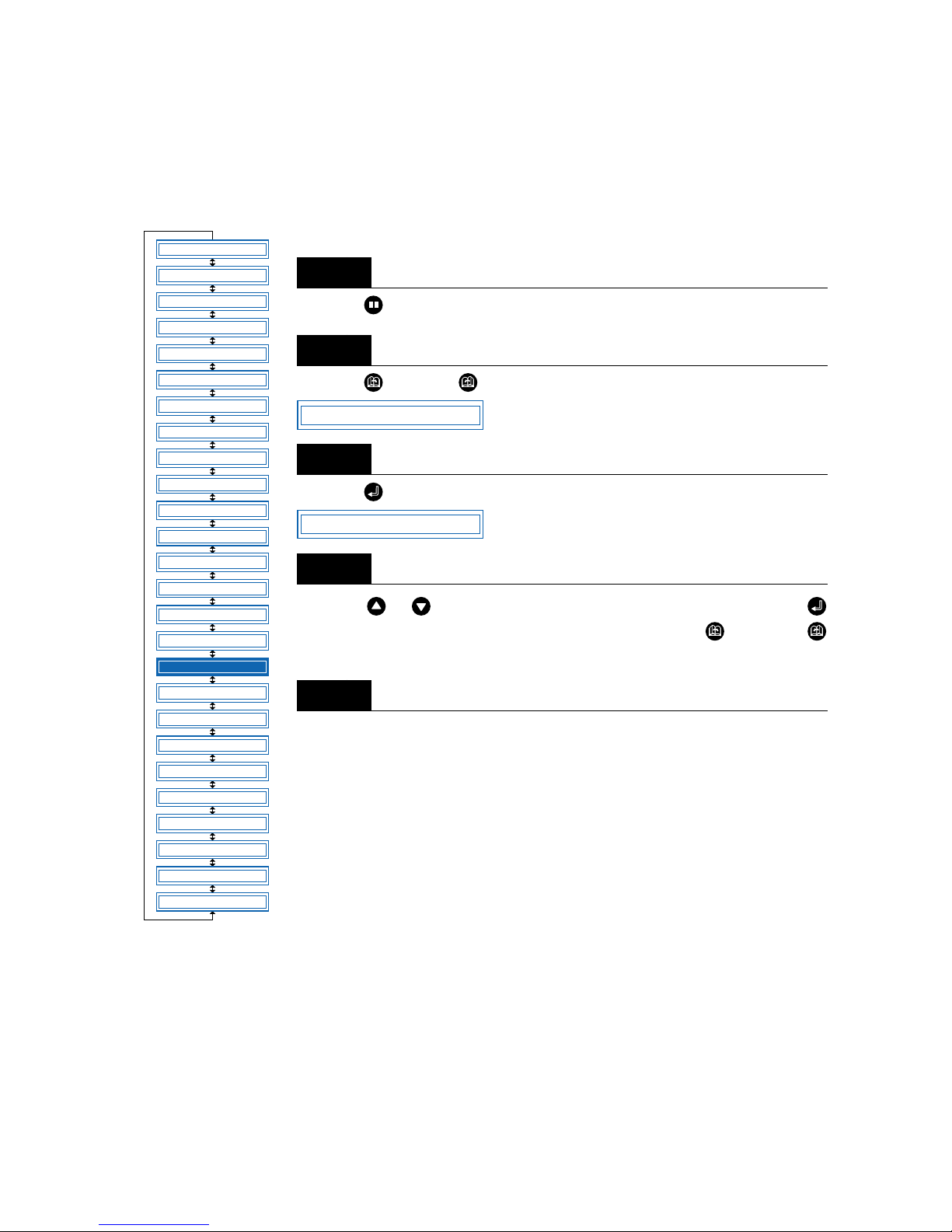
4 – 35
4.18 Setting the Format of Data to be Received
Before data is sent from the computer, the format (command mode) of data sent by the application software must be checked. The cutting plotter accepts two data formats (command modes): GP-GL and HPGL commands. Set the command mode to suit the application used.
■Setting the Command Mode
Press the (PAUSE) key to switch to PAUSE mode.
Press the (NEXT) or (PREV.) key until the following menu is displayed.
Press the (ENTER) key to display the command-setting menu.
Press the or key to select “GP-GL” or “HP-GL,” and then press the
(ENTER) key to confirm. To cancel the selection, press the (NEXT) or
(PREV.) key.
If “GP-GL” is selected, set the STEP SIZE. If “HP-GL” is selected, set the ORIGIN
POINT. If a command different from that set previously is selected, the PAUSE
mode is automatically canceled after STEP SIZE (GP-GL) or ORIGIN POINT (HPGL) is set.
Step
1
Step
2
Step
3
Step
4
Step
5
FEED
MOVE TO R. MARK
AUTO PRE FEED
TANGENTIAL
AUTO REG. MARK
CLEAR BUFFER
AXIS ALIGNMENT
DISTANCE ADJUST
PAGE LENGTH
PLOT AREA
EXPAND
ROTATE
MIRROR
COPY
SORT
RS-232C
COMMAND
BLADE WEAR SETUP
PEN UP/DOWN
TEST MODE
PEN UP SPEED
OFFSET FORCE
OFFSET ANGLE
STEP PASS
INIT. DOWN FORCE
LENGTH UNIT
*
*
*: Option
COMMAND
COMMAND GP-GL
Page 78

4 – 36
■ Setting the STEP SIZE
If the GP-GL command mode is set, the minimum unit of distance that the pen can travel can be changed
to one of four settings: 0.01 mm, 0.025 mm, 0.05 mm, or 0.1 mm. The default setting is 0.1 mm, so change
this setting if your application specifies a different step size.
Set the command setting to “GP-GL.”
Press the (ENTER) key to display the step-size setting menu.
Press the or key to select “0.100 mm,” “0.050 mm,” “0.025 mm,” or “0.010 mm,” and then press
the (ENTER) key to confirm. To cancel the selection, press the (NEXT) or (PREV.) key.
Press the (PAUSE) key to cancel PAUSE mode.
■ Setting the ORIGIN POINT
If the HP-GL command mode is set, the origin point can be set to the lower left or center. The default setting is the lower left, so change this setting if your application specifies a different origin position.
Set the command setting to “HP-GL.”
Press the (ENTER) key to display the origin-point setting.
Press the or key to select “L.L. (LOWER LEFT)” or “CENTER,” and then press the (ENTER)
key to confirm. To cancel the selection, press the (NEXT) or (PREV.) key.
Press the (PAUSE) key to cancel PAUSE mode.
Step
1
Step
2
Step
3
Step
4
Step
1
Step
2
Step
3
Step
4
COMMAND GP-GL
STEP SIZE 0.100mm
COMMAND HP-GL
ORIGIN PT L.L.
Page 79

4 – 37
4.19 Blade Wear Detection (When Blade Wear Setup is On)
This function calculates the total cutting distance of the cutter blade to indicate when it requires replacement. This should be used purely as a guide, as the actual cutter-blade wear will vary depending on the
material cut and the cutting conditions (e.g., force) used.
The pen setting areas are grouped together, and the total distances are calculated for each group. Eight
groups can be managed, and they initially correspond to the pen setting areas, so that group 1 corresponds to setting area 1, group 2 corresponds to setting area 2, and so on. If tw o or more setting areas are
combined in a single group, the total calculated distance for that group will be the sum of the individual
area values.
It is also possible to include weighting factors f or each setting area to correspond to the different wear rates
for different materials and cutting conditions. For example, if setting areas 1, 2, and 3 are combined into
one group with respective total distances of A, B, and C, and the respective factors are 0.7, 1.2, and 1.0,
the total distance for this group will be A x 0.7 + B x 1.2 + C x 1.0.
Wear detection can be switched on or off using the special function settings (see “Enabling/Disabling Wear
Detection” on page 5-3). When disabled, it is not displayed on the PAUSE menu.
If the power is turned off while cutting is in progress, the cutting distance for that operation is not included
in wear-detection calculations.
■ Checking the Wear Rate
Check to confirm that the cutting plotter is in READY mode (displaying the current pen settings).
Press the (NEXT) key to display the wear-rate menu for the group to which the above setting area
belongs.
The wear rate is shown as 0% for a new pen, and 100% when the total distance exceeds the maximum
distance for the cutter blade. Press the (PREV.) key to return to READY mode.
The following message is displayed in READY mode if the wear rate exceeds 100% for the group to which
the current setting area belongs.
This indication should be used as a guide for cutter-blade replacement.
This display reverts to the normal READY-mode display when the (PREV.) key is pressed, but it will
reappear when the power is turned on again or if a setting area is selected again for a group with a wear
rate exceeding 100%.
Always zero the total distance displa y after replacing a cutter b lade (see “Clearing the Total Distance (Wear
Rate)”). The display above will disappear, and the distance calculation will restart from zero.
Step
1
Step
2
Step
3
1 PEN 23 30 2
BLADE WEAR 60%
EXCEEDS 100%
Page 80
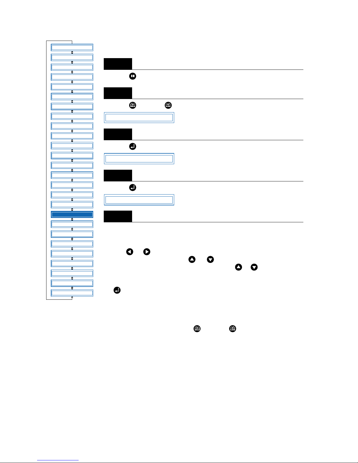
4 – 38
■Setting Wear-Rate Groups
This registers setting areas in groups.
Press the (PAUSE) key to switch to PAUSE mode.
Press the (NEXT) or (PREV.) key until the following menu is displayed.
Press the (ENTER) key to display the wear-rate setting submenu.
Press the (ENTER) key to display the wear-rate group setting.
The number on the left is the group number, and the numbers to the right of this
indicate the setting areas belonging to it, separated by spaces. The display above
indicates setting areas 1, 2, 4, and 5, belonging to group 1.
Use the or key to move the cursor to the group number or setting-area
number to be set. Pressing the or key at the group-number position
increases or decreases the number, and pressing the or key at the setting-
area number position displays or doesn’t display the number. Select the required
group number, display the setting-area numbers to be registered, and then press
the (ENTER) key to confirm.
Each setting area can only be registered in one group. To register a setting area in
another group, it must first be removed from the group in which it is registered. Initially, setting area 1 is set to group 1, setting area 2 to group 2, and so on, so setting areas must be removed from one group before being registered in another.
To cancel the selection(s), press the (NEXT) or (PREV.) key.
Step
1
Step
2
Step
3
Step
4
Step
5
FEED
MOVE TO R. MARK
AUTO PRE FEED
TANGENTIAL
AUTO REG. MARK
CLEAR BUFFER
AXIS ALIGNMENT
DISTANCE ADJUST
PAGE LENGTH
PLOT AREA
EXPAND
ROTATE
MIRROR
COPY
SORT
RS-232C
COMMAND
BLADE WEAR SETUP
PEN UP/DOWN
TEST MODE
PEN UP SPEED
OFFSET FORCE
OFFSET ANGLE
STEP PASS
INIT. DOWN FORCE
LENGTH UNIT
*
*
*: Option
BLADE WEAR SETUP
SET BLADE GROUP
GROUP 1 12 45
Page 81
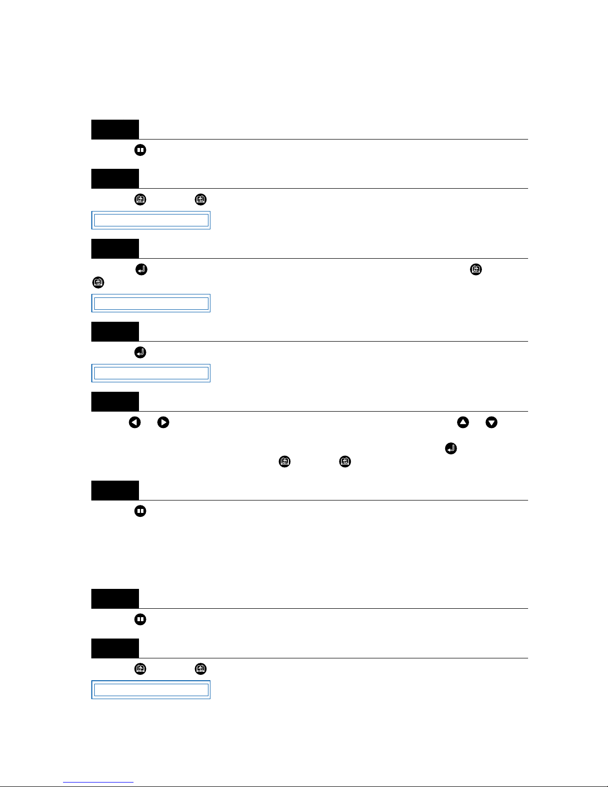
4 – 39
■ Setting Wear-Rate Factors
This sets factors corresponding to the differences in wear rates due to different materials and cutting conditions.
Press the (PAUSE) key to switch to PAUSE mode.
Press the (NEXT) or (PREV.) key until the following menu is displayed.
Press the (ENTER) key to display the wear-rate setting submenu, and then press the (NEXT) or
(PREV.) key until the following menu is displayed.
Press the (ENTER) key to display the wear-rate factor setting.
Use the or key to increase or decrease the setting-area number, and use the or key to
increase or decrease the factor value. The factor can be set to between 0.10 and 1.00 in 0.10 intervals, and
between 1.00 and 2.50 in 0.25 intervals. Once the wear-rate factor is set, press the (ENTER) key to
confirm. To cancel the selection(s), press the (NEXT) or (PREV.) key.
Press the (PAUSE) key to cancel PAUSE mode.
■ Clearing the Total Distance (Wear Rate)
Always zero the total-distance display when a cutter blade has been replaced. This starts the total-distance
calculation from zero.
Press the (PAUSE) key to switch to PAUSE mode.
Press the (NEXT) or (PREV.) key until the following menu is displayed.
Step
1
Step
2
Step
3
Step
4
Step
5
Step
6
Step
1
Step
2
BLADE WEAR SETUP
FACTOR
COND 1 1.00
BLADE WEAR SETUP
Page 82
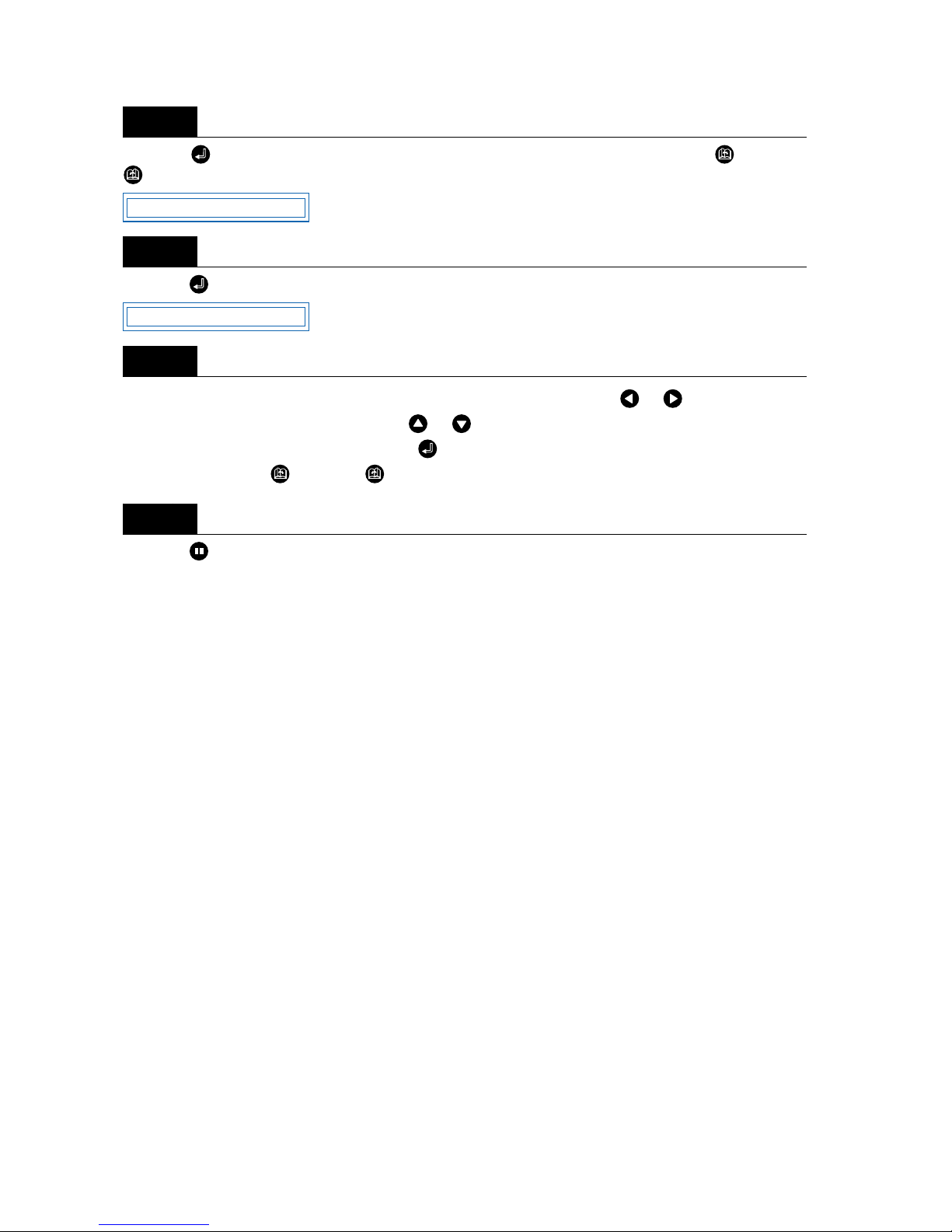
4 – 40
Press the (ENTER) key to display the wear-rate setting submenu, and then press the (NEXT) or
(PREV.) key until the following menu is displayed.
Press the (ENTER) key to display the wear-rate clear menu.
The number to the right of “CLEAR GROUP” is the group number. Use the or key to increase or
decrease the group number, and press the or key to select “YES” or “NO.” Select “YES” for the
group number to be cleared, and press the (ENTER) key to clear the total distance. To cancel the
selection(s), press the (NEXT) or (PREV.) key.
Press the (PAUSE) key to cancel PAUSE mode.
Step
3
Step
4
Step
5
Step
6
CLEAR GROUP
CLEAR GROUP1<YES>
Page 83
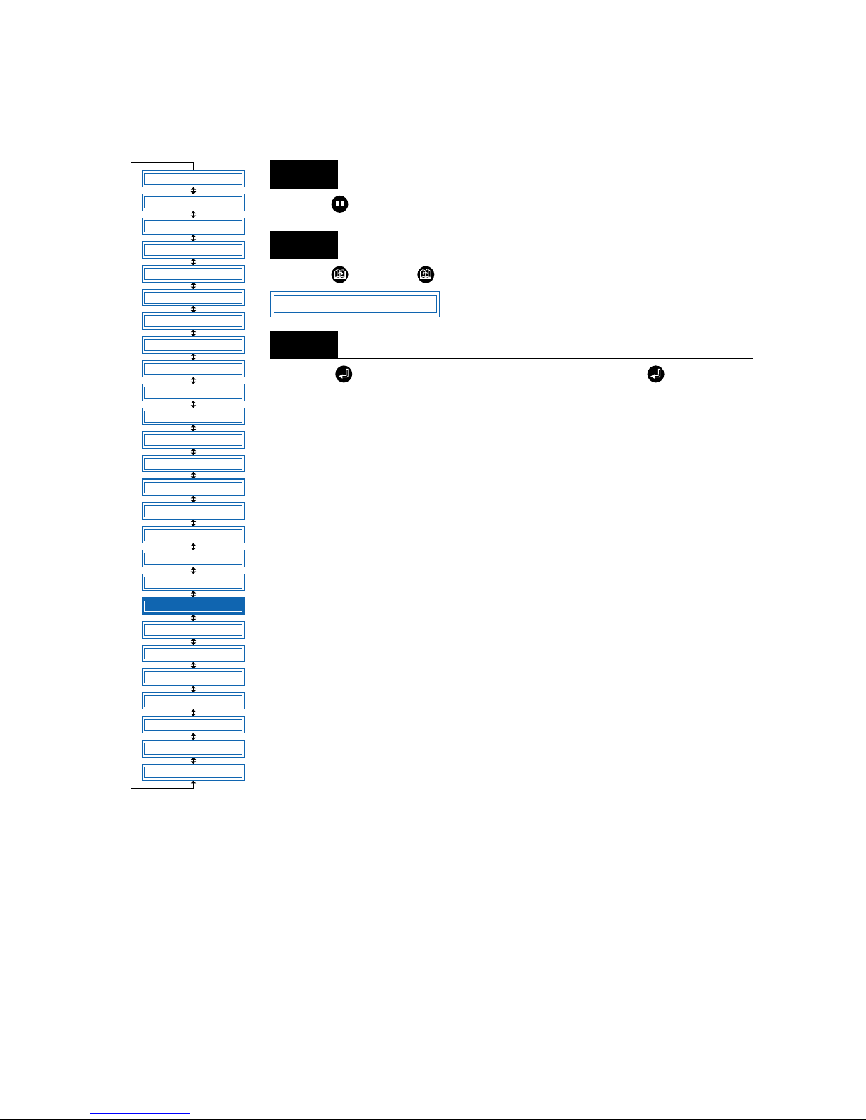
4 – 41
4.20 Raising and Lowering the Pen
This function raises and lowers the pen.
Press the (PAUSE) key to switch to PAUSE mode.
Press the (NEXT) or (PREV.) key until the following menu is displayed.
Press the (ENTER) key to lower the pen, and press the (ENTER) key
again to raise it.
Step
1
Step
2
Step
3
FEED
MOVE TO R. MARK
AUTO PRE FEED
TANGENTIAL
AUTO REG. MARK
CLEAR BUFFER
AXIS ALIGNMENT
DISTANCE ADJUST
PAGE LENGTH
PLOT AREA
EXPAND
ROTATE
MIRROR
COPY
SORT
RS-232C
COMMAND
BLADE WEAR SETUP
PEN UP/DOWN
TEST MODE
PEN UP SPEED
OFFSET FORCE
OFFSET ANGLE
STEP PASS
INIT. DOWN FORCE
LENGTH UNIT
*
*
*: Option
PEN UP/DOWN
Page 84
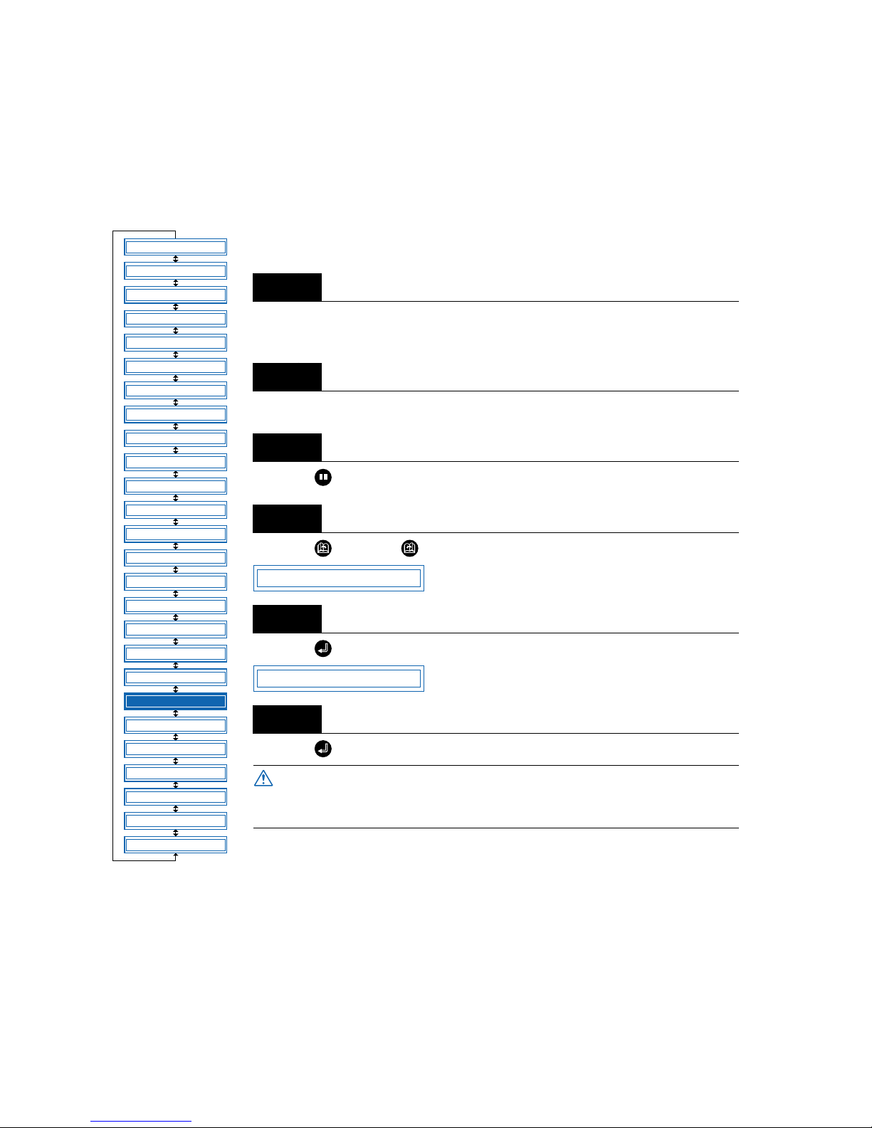
4 – 42
4.21 TEST Mode
The cutting plotter has three test modes: “Condition print (COND. PAT.)” for the printing of setting details,
“Dump mode” for checking data transfers from the computer, and “Cutting force test cutting (PRESS
TEST CUT)” for performing five test cuts. These should be used to check the various settings and to check
for problems.
■Condition-List Printing
This function prints out the setting details currently in use.
Mount a plotting pen in the pen carriage, and set the conditions to suit the pen
used (e.g., force, pen speed settings).
Load an A4-size or larger medium.
Press the (PAUSE) key to switch to PAUSE mode.
Press the (NEXT) or (PREV.) key until the following menu is displayed.
Press the (ENTER) key to display the test-mode submenu.
Press the (ENTER) key to start printing the condition list.
Step
1
Step
2
Step
3
Step
4
Step
5
Step
6
The pen carriage begins moving as soon as this function is set.
Keep your hands and other objects away from the cutting plotter’s moving parts.
FEED
MOVE TO R. MARK
AUTO PRE FEED
TANGENTIAL
AUTO REG. MARK
CLEAR BUFFER
AXIS ALIGNMENT
DISTANCE ADJUST
PAGE LENGTH
PLOT AREA
EXPAND
ROTATE
MIRROR
COPY
SORT
RS-232C
COMMAND
BLADE WEAR SETUP
PEN UP/DOWN
TEST MODE
PEN UP SPEED
OFFSET FORCE
OFFSET ANGLE
STEP PASS
INIT. DOWN FORCE
LENGTH UNIT
*
*
*: Option
TEST
COND. PAT.
CAUTION
Page 85

4 – 43
■ Dump Mode
This function checks whether data is sent correctly from the computer. If the output data does not match
the program after the dump list has been output, check the transfer conditions and connections.
Mount a plotting pen in the pen carriage, and set the conditions to suit the pen used (e.g., force, pen speed
settings).
Load an A4-size or larger medium.
Press the (PAUSE) key to switch to PAUSE mode.
Press the (NEXT) or (PREV.) key until the following menu is displayed.
Press the (ENTER) key to display the test-mode submenu, and then press the (NEXT) or
(PREV.) key until the following menu is displayed.
Press the (ENTER) key to switch to dump mode.
When data is sent to the cutting plotter in this mode, a dump list is printed out. To exit the dump mode, turn
on the power again.
Step
1
Step
2
Step
3
Step
4
Step
5
Step
6
Step
7
The dump list is printed out as ASCII character codes. Characters without codes
will be printed as small 2-digit figures. Output data for READ-type commands will
be output as dummy data, except for cutting-plotter status output.
The pen carriage begins moving as soon as this function is set. Keep your hands and
other objects away from the cutting plotter’s moving parts.
TEST MODE
DUMP
CHAR DUMP MODE
CHECKPOINT
CAUTION
Page 86

4 – 44
■ Cutting Force Test Cutting
The cutting force can be changed in one-step increments from its current setting (in the range -2 to +2) to
enable five test cuts to be performed. Test cutting can be performed after selecting the TOOL (cutter b lade)
and specifying the cutter-blade length, OFFSET, FORCE, SPEED, and QUALITY settings to ensure that
the selected cutting conditions actually produce the desired cutting results. Check how far the blade cuts
into the film and how the corners are being cut. If the cutting results are not satisfactory, reset the cutterpen conditions and repeat the test cutting until the optimal settings are achieved. Test cutting will be carried
out according to the conditions currently set for the cutter-pen.
Mount a cutter pen in the pen carriage, and specify cutting conditions suitable for the mounted cutter pen
(see “3.3 Setting the Cutter-Pen Conditions.”)
Load a sheet of film for cutting.
Press the (PAUSE) key to switch to PAUSE mode.
Press the (NEXT) or (PREV.) key until the following menu is displayed.
Press the (ENTER) key to display the Test Mode submenu, and then press the (NEXT) or
(PREV.) key until the following menu is displayed.
To change the cutting conditions, press the (COND.) key to display the conditions setting menu. When
you exit the conditions setting menu, the display retur ns to the menu shown in Step 5. For more infor mation on the conditions setting menu, see “3.3 Setting the Cutter-Pen Conditions.”
Step
1
Step
2
Step
3
Step
4
Step
5
Step
6
TEST MODE
PRESS TEST CUT
Page 87
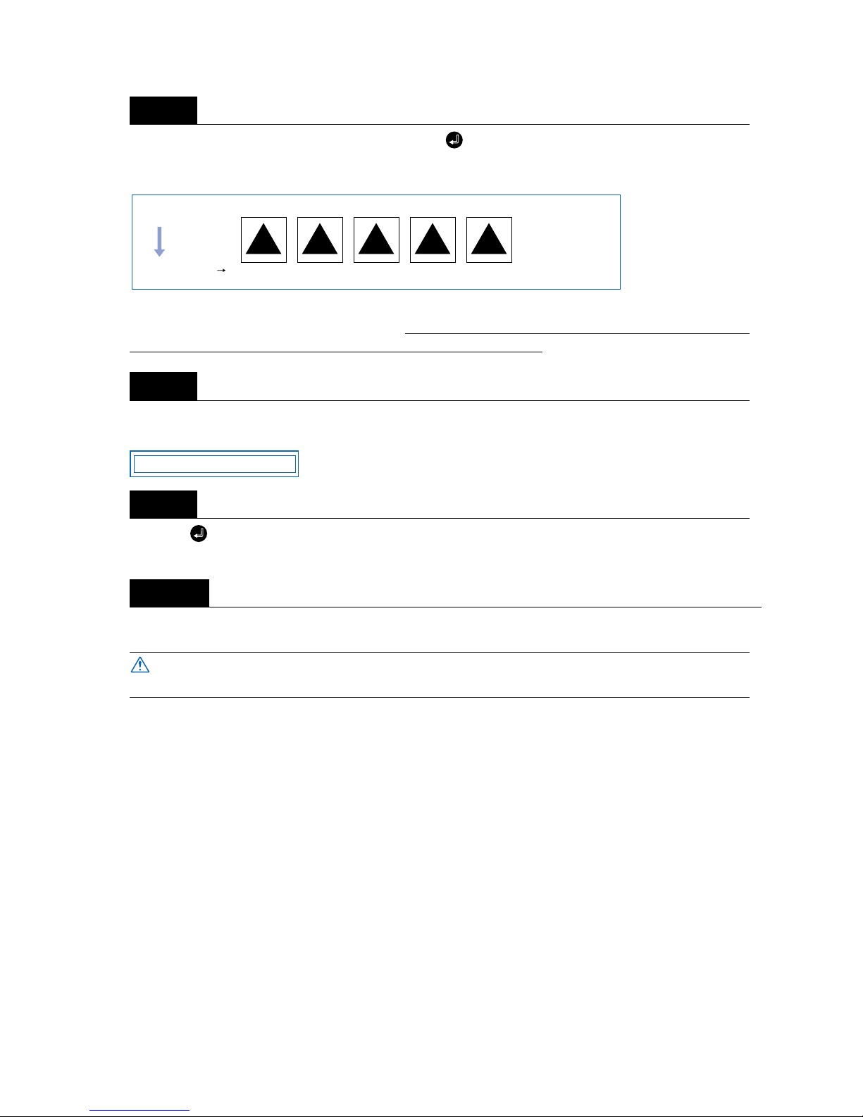
4 – 45
With the menu shown in Step 5 displayed, press the (ENTER) key to start test cutting. Five test cuts
will be performed in the range from “-2” to “+2”, with the current FORCE as “0.” Test cutting will be per-
formed from the current pen position.
Adjust the OFFSET value to suit the type and thickness of the film being used, and finely adjust the finish
of each corner. For the FORCE value setting, make your selection from the five test cuts. In test cutting,
adjust the blade length so that the backing sheet is only slightly scored.
When test cutting has been completed, the pen carriage moves to the standby position and the following
menu is displayed.
Press the (ENTER) key to return the pen carriage to its previous position and to switch the cutting plotter to READY mode.
Upon completion of fine adjustment, send actual cutting data to the cutting plotter for cutting.
Step
7
Step
8
Step
9
Step
10
The pen carriage begins moving as soon as this function is set. Keep your hands and
other objects away from the cutting plotter’s moving parts.
210-1-2FORCE
Medium feed direciton
PRESS ENTER KEY
CAUTION
Page 88
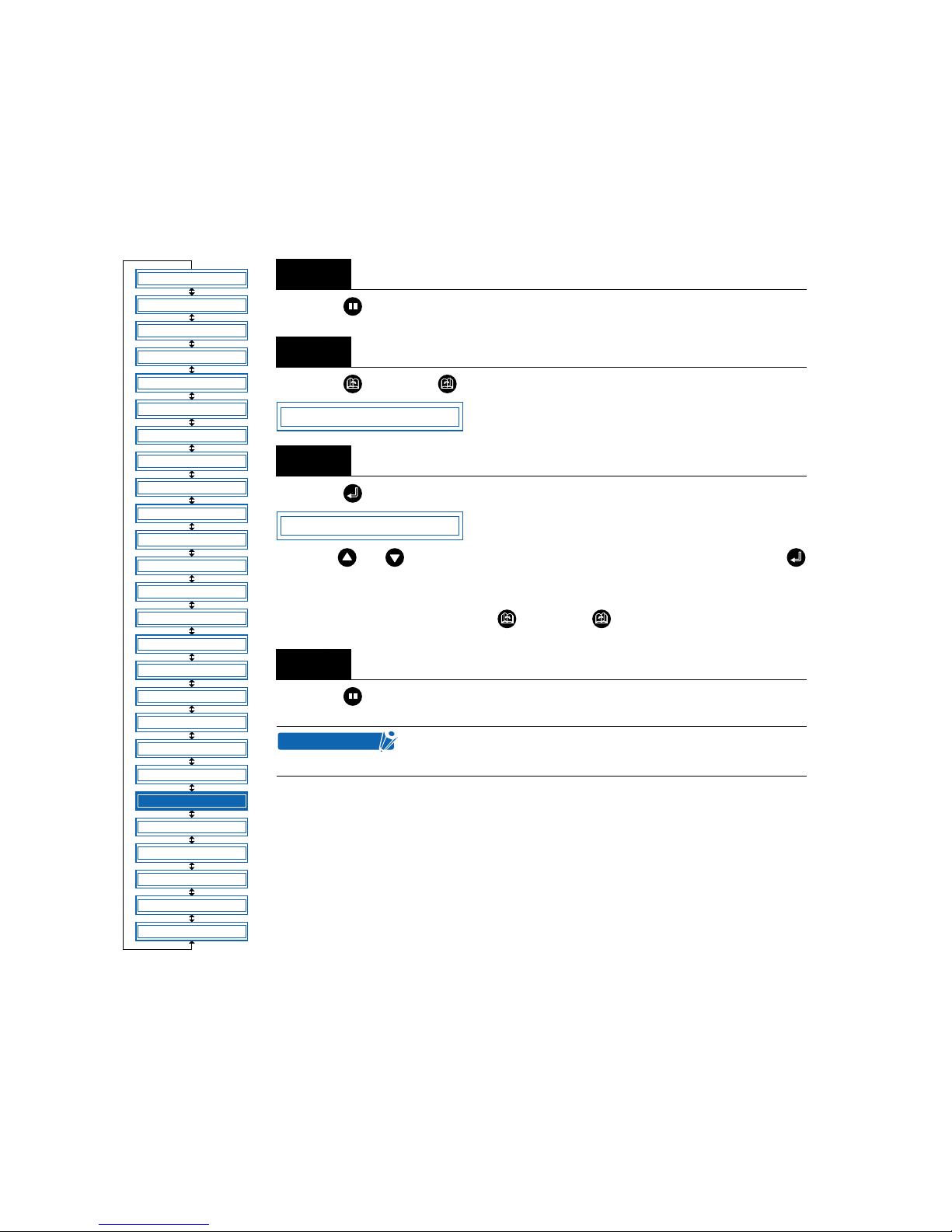
4 – 46
4.22 Setting the PEN UP SPEED
This function sets the travel speed of the pen when it is raised. It can be specified independently of the cutting SPEED function. When the PEN UP SPEED is high, the pen travels faster when it is raised, thereby
reducing the overall cutting time. Your cutting plotter comes with its PEN UP SPEED set to AUTO, which
selects the same speed as the cutting SPEED function (pen lowered). Note that if long-axis cutting of a
medium is performed with a high PEN UP SPEED setting, the medium is susceptible to jamming.
Press the (PAUSE) key to switch to PAUSE mode.
Press the (NEXT) or (PREV.) key until the following menu is displayed.
Press the (ENTER) key to display the pen-up-speed menu.
Use the or key to select the value to be set, and then press the
(ENTER) key to confirm.
“AUTO” “10” “20” “30” “45” cm/s
To cancel the selection, press the (NEXT) or (PREV.) key.
Press the (PAUSE) key to cancel PAUSE mode.
Step
1
Step
2
Step
3
Step
4
This setting is retained in the internal memory even when
the power is turned off.
FEED
MOVE TO R. MARK
AUTO PRE FEED
TANGENTIAL
AUTO REG. MARK
CLEAR BUFFER
AXIS ALIGNMENT
DISTANCE ADJUST
PAGE LENGTH
PLOT AREA
EXPAND
ROTATE
MIRROR
COPY
SORT
RS-232C
COMMAND
BLADE WEAR SETUP
PEN UP/DOWN
TEST MODE
PEN UP SPEED
OFFSET FORCE
OFFSET ANGLE
STEP PASS
INIT. DOWN FORCE
LENGTH UNIT
*
*
*: Option
PEN UP SPEED
UP SPEED = AUTO
CHECKPOINT
Page 89
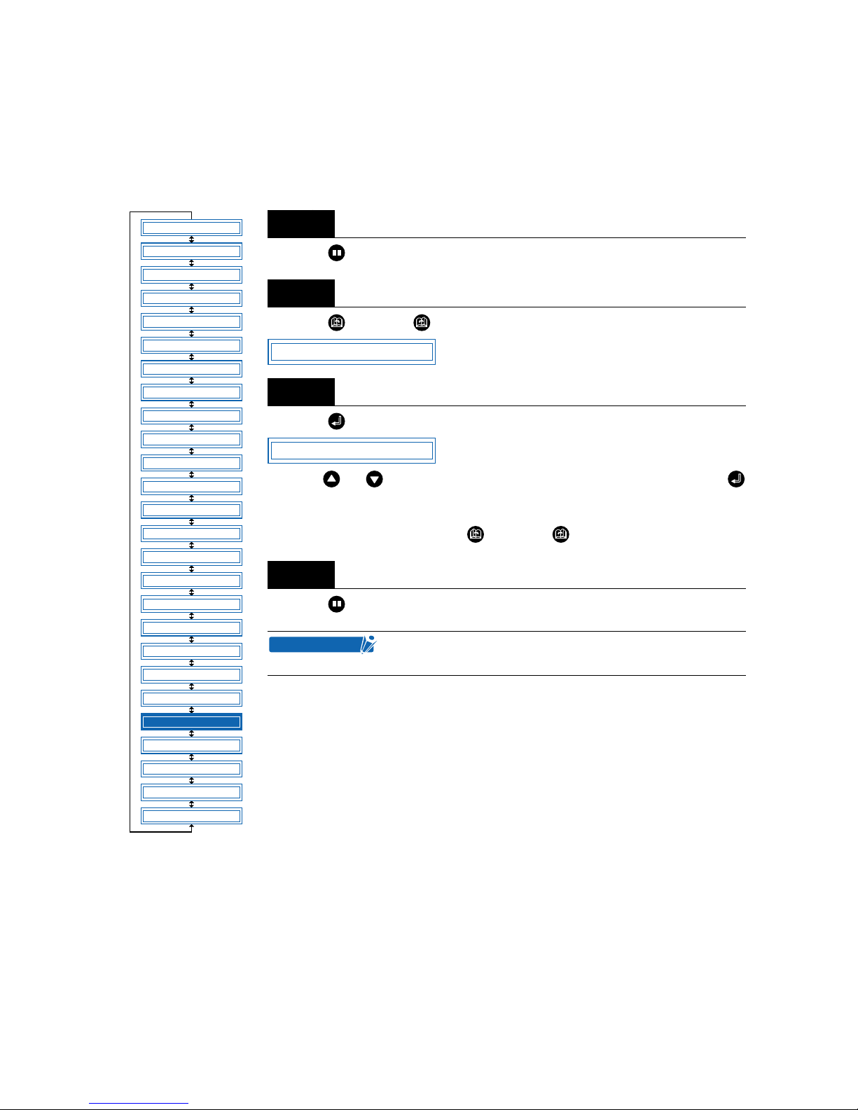
4 – 47
4.23 Setting the OFFSET FORCE (Initial Cutting Force)
This function specifies the cutting force to be applied during initial blade control for checking the cutterblade direction at the start of operation. This is used to control the rotation of the cutter-blade tip during initial blade control when thick media is cut, and is therefore not necessary to specify for media of regular
thickness. The initial setting is “4.” Increasing this setting increases the cutting force.
Press the (PAUSE) key to switch to PAUSE mode.
Press the (NEXT) or (PREV.) key until the following menu is displayed.
Press the (ENTER) key to display the offset-force setting menu.
Use the or key to select the value to be set, and then press the
(ENTER) key to confirm.
“1” to “31”
To cancel the selection, press the (NEXT) or (PREV.) key.
Press the (PAUSE) key to cancel PAUSE mode.
Step
1
Step
2
Step
3
Step
4
This setting is retained in the internal memory even when
the power is turned off.
FEED
MOVE TO R. MARK
AUTO PRE FEED
TANGENTIAL
AUTO REG. MARK
CLEAR BUFFER
AXIS ALIGNMENT
DISTANCE ADJUST
PAGE LENGTH
PLOT AREA
EXPAND
ROTATE
MIRROR
COPY
SORT
RS-232C
COMMAND
BLADE WEAR SETUP
PEN UP/DOWN
TEST MODE
PEN UP SPEED
OFFSET FORCE
OFFSET ANGLE
STEP PASS
INIT. DOWN FORCE
LENGTH UNIT
*
*
*: Option
OFFSET FORCE
OFFSET FORCE 4
CHECKPOINT
Page 90
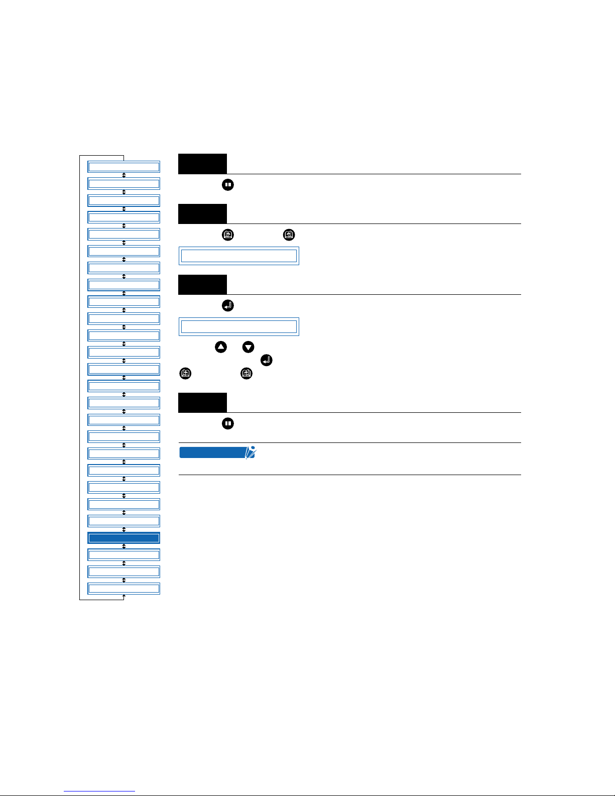
4 – 48
4.24 Setting the OFFSET ANGLE
This function sets the reference value used to adjust the cutter-blade offset angle to correspond to the displacement of the traveling angle as defined by the coordinate movement data received. The cutter blade is
controlled above the angle specified. Setting a high value will reduce the total cutting time, but the corners
of drawings cut will become rounded and may not be cut precisely. The initial setting is “30.”
Press the (PAUSE) key to switch to PAUSE mode.
Press the (NEXT) or (PREV.) key until the following menu is displayed.
Press the (ENTER) key to display the offset-angle setting menu.
Use the or key to select the required value within the range of “0” to “60,”
and then press the (ENTER) key to confirm. To cancel the selection, press the
(NEXT) or (PREV.) key.
Press the (PAUSE) key to cancel PAUSE mode.
Step
1
Step
2
Step
3
Step
4
This setting is retained in the internal memory even when
the power is turned off.
FEED
MOVE TO R. MARK
AUTO PRE FEED
TANGENTIAL
AUTO REG. MARK
CLEAR BUFFER
AXIS ALIGNMENT
DISTANCE ADJUST
PAGE LENGTH
PLOT AREA
EXPAND
ROTATE
MIRROR
COPY
SORT
RS-232C
COMMAND
BLADE WEAR SETUP
PEN UP/DOWN
TEST MODE
PEN UP SPEED
OFFSET FORCE
OFFSET ANGLE
STEP PASS
INIT. DOWN FORCE
LENGTH UNIT
*
*
*: Option
OFFSET ANGLE
OFFSET ANGLE 30
CHECKPOINT
Page 91
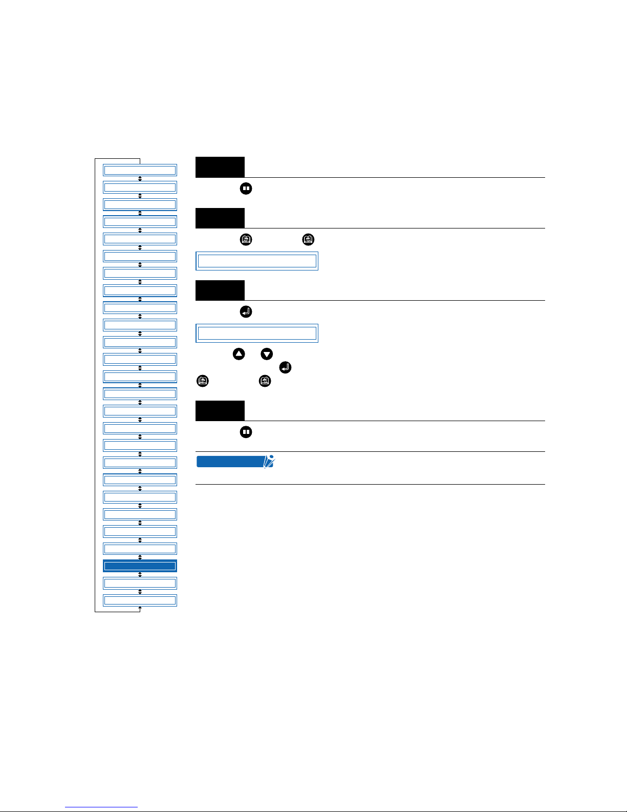
4 – 49
4.25 Setting the STEP PASS
Reducing this setting increases image quality by enabling smooth cutter-blade tip control when arcs are
cut. The STEP PASS setting speci fied is used as the unit for blade tip control, with blade tip control omitted
for any data below the STEP PASS setting. If the STEP PASS setting is too high, the image cut may not be
faithfully reproduced. Normally, the STEP PASS setting should be set to “1.”
Press the (PAUSE) key to switch to PAUSE mode.
Press the (NEXT) or (PREV.) key until the following menu is displayed.
Press the (ENTER) key to display the step-pass setting menu.
Use the or key to select the required value within the range of “0” to “20,”
and then press the (ENTER) key to confirm. To cancel the selection, press the
(NEXT) or (PREV.) key.
Press the (PAUSE) key to cancel PAUSE mode.
Step
1
Step
2
Step
3
Step
4
This setting is retained in the internal memory even when
the power is turned off.
FEED
MOVE TO R. MARK
AUTO PRE FEED
TANGENTIAL
AUTO REG. MARK
CLEAR BUFFER
AXIS ALIGNMENT
DISTANCE ADJUST
PAGE LENGTH
PLOT AREA
EXPAND
ROTATE
MIRROR
COPY
SORT
RS-232C
COMMAND
BLADE WEAR SETUP
PEN UP/DOWN
TEST MODE
PEN UP SPEED
OFFSET FORCE
OFFSET ANGLE
STEP PASS
INIT. DOWN FORCE
LENGTH UNIT
*
*
*: Option
STEP PASS
STEP PASS 1
CHECKPOINT
Page 92
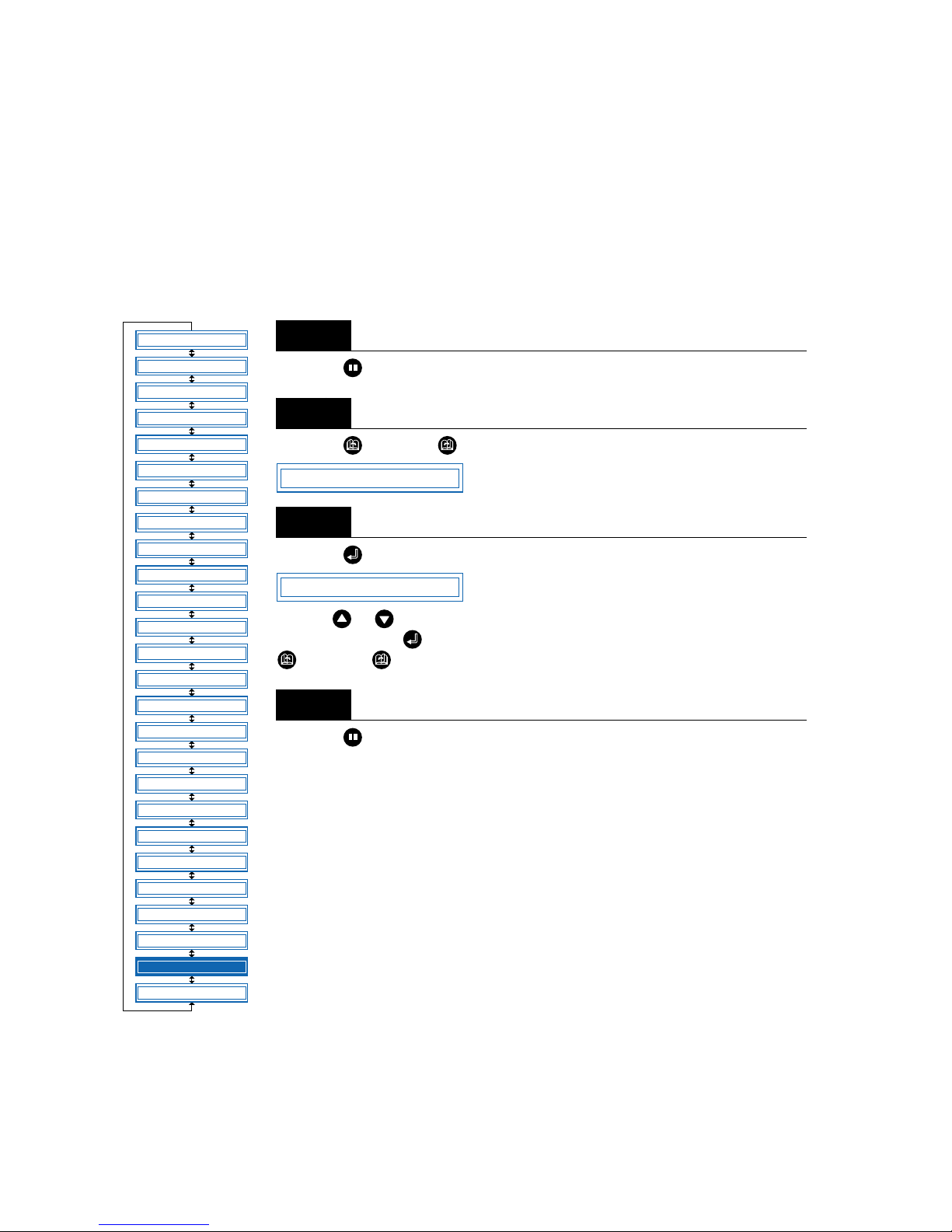
4 – 50
4.26 Setting the Initial Down Force
The initial down-force setting is useful when TANGENTIAL mode is selected (f or the cutting of thic k media).
With thick film, additional time is required for the cutter blade to penetrate the film fully, even when the necessary cutting force is applied. The cutting operation starts before the cutter blade has fully penetrated the
film, causing uncut sections to be left. When the initial down force is specified, this force is used as the cut-
ting force immediately after lowering of the pen when TANGENTIAL mode is selected, enabling the cutter
blade to penetrate the medium rapidly. (If the cutting force is 25 and the initial down force is 4, for example,
the cutting force applied immediately after lowering of the pen will be 29.) Set the initial down force to suit
the type of film used by performing test cuts.
Press the (PAUSE) key to switch to PAUSE mode.
Press the (NEXT) or (PREV.) key until the following menu is displayed.
Press the (ENTER) key to display the initial-cutting-force setting menu.
Use the or key to select the required value within the range of “0” to “20,”
and then press the (ENTER) key to confirm. To cancel the selection, press the
(NEXT) or (PREV.) key.
Press the (PAUSE) key to cancel PAUSE mode.
Step
1
Step
2
Step
3
Step
4
FEED
MOVE TO R. MARK
AUTO PRE FEED
TANGENTIAL
AUTO REG. MARK
CLEAR BUFFER
AXIS ALIGNMENT
DISTANCE ADJUST
PAGE LENGTH
PLOT AREA
EXPAND
ROTATE
MIRROR
COPY
SORT
RS-232C
COMMAND
BLADE WEAR SETUP
PEN UP/DOWN
TEST MODE
PEN UP SPEED
OFFSET FORCE
OFFSET ANGLE
STEP PASS
INIT. DOWN FORCE
LENGTH UNIT
*
*
*: Option
INIT.DOWN FORCE
INIT.DOWN F. 0
Page 93
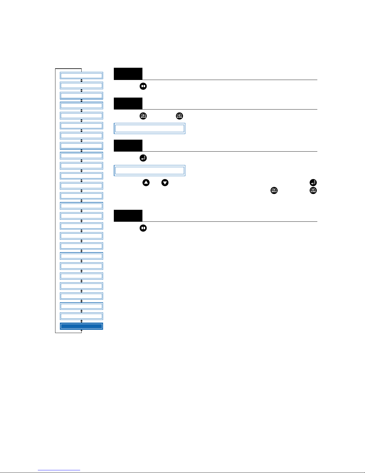
4 – 51
4.27 Setting the LENGTH UNIT
This function specifies the units for coordinates displayed in millimeters or inches.
Press the (PAUSE) key to switch to PAUSE mode.
Press the (NEXT) or (PREV.) key until the following menu is displayed.
Press the (ENTER) key to display the length-unit menu.
Press the or key to select “mm” or “inch,” and then press the
(ENTER) key to confirm. To cancel the selection, press the (NEXT) or
(PREV.) key.
Press the (PAUSE) key to cancel PAUSE mode.
Step
1
Step
2
Step
3
Step
4
FEED
MOVE TO R. MARK
AUTO PRE FEED
TANGENTIAL
AUTO REG. MARK
CLEAR BUFFER
AXIS ALIGNMENT
DISTANCE ADJUST
PAGE LENGTH
PLOT AREA
EXPAND
ROTATE
MIRROR
COPY
SORT
RS-232C
COMMAND
BLADE WEAR SETUP
PEN UP/DOWN
TEST MODE
PEN UP SPEED
OFFSET FORCE
OFFSET ANGLE
STEP PASS
INIT. DOWN FORCE
LENGTH UNIT
*
*
*: Option
LENGTH UNIT
LENGTH UNIT mm
Page 94

4 – 52
Page 95

5
5
Setting and Using the Special Functions
5.1 Description of Special Functions A.....................................5-2
5.2 Setting Special Functions A...................................................5-4
5.3 Description of Special Functions B.....................................5-4
5.4 Setting Special Functions B...................................................5-5
Page 96

5 – 2
5.1 Description of Special Functions A
The cutting plotter is provided with the special functions described below. These functions are specified
only in special situations, and are not normally used.
■ Enabling/Disabling the “:” and “;” Commands (when the COMMAND setting is GP-GL)
This function enables or disables the “:” and “;” commands when the COMMAND setting is GP-GL. If the
first part of the data is lost, these commands may be having an adverse effect. In this case, set this func-
tion to DISABLED (the default setting is ENABLED).
■ Moving the Pen While Raised or Lowered in Response to the “W” Command (when the
COMMAND setting is GP-GL)
This function selects whether, upon receipt of the “W” command for the drawing of arcs, the cutting plotter
moves the pen to the specified starting position, raised or in the pen status (raised or lowered) that was in
effect immediately prior to receipt of the “W” command.
When PEN DOWN is selected, the pen is moved to the starting position for the drawing of arcs in the pen
status (raised or lowered) that was in effect immediately prior to receipt of the “W” command.
When PEN UP is selected, the pen is moved to the starting position for the drawing of arcs in the raised
status. This setting is only effective if a cutter blade has been selected in the cutter-pen settings.
(The default setting is PEN UP.)
■ Model ID Response (when the COMMAND setting is HP-GL)
This function sets the response to the “OI” command when the COMMAND setting is HP-GL.
When 7550 is set, the “OI” command response is 7550.
When 7586 is set, the “OI” command response is 7586.
(The default setting is 7550.)
■ SETTING PRIORITY
This function sets whether the cutting plotter places priority on the cutting conditions specified through
command input from the computer or through manual settings (on the cutting-plotter control panel).
When MANUAL is selected, cutting is performed using the cutting conditions set at the control panel, and
cutting conditions sent from the computer are ignored.
When PROGRAM is selected, cutting is performed using the cutting conditions specified in a received cutting-condition command. If no commands are received, cutting is performed using the cutting conditions
set at the control panel.
(The default setting is MANUAL.)
■ Blade-Tip Initial Position Setting
The cutter blade is placed on the medium to orient it after the power is turned on or the cutter-pen conditions are set. This is referred to as “initializing” the cutter blade.
This function sets the “Blade-Tip Initial Position” for this operation.
When 2 mm BELOW is selected, initial blade control is performed at a position 2 mm below the cutting
start position.
When OUTSIDE is selected, initial blade control is performed outside of the effective cutting/plotting area.
(The default setting is 2 mm BELOW.)
Page 97

5 – 3
■ Enabling/Disabling PEN UP MOVE
This function sets whether the pen will travel to each point specified or only from the initially specified point
to the last specified point when consecutive commands are received specifying pen movement while it is
raised.
When ON is selected, the pen travels consecutively to each coordinate specified by the data received.
When OFF is selected, the pen travels directly from the initially specified point to the last specified point.
(The default setting is OFF.)
■ Enabling/Disabling the Media Sensors
This function sets the media sensors that detect the size of the medium in the feed direction.
When ON is selected, the feed-direction media sensors are enabled.
When OFF is selected, the feed-direction media sensors are disabled.
(The default setting is ON.)
■ Enabling/Disabling the Home Sensors
This function sets the home sensors that detect the width of the medium.
When ON is selected, the home sensors are enabled.
When OFF is selected, the home sensors are disabled.
(The default setting is ON.)
■ Setting the PARALLEL I/F Mode
Parallel (Centronics-compatible) interfaces have various timing methods for their signal lines. If the signal
timings do not match, data cannot be received accurately via the Centronics-compatible parallel interface.
This function allows the timing of the Centronics-compatible parallel interface to be changed by selecting
one of four different modes (1 through 4).
(The default setting is 1.)
■ Circle-Command Resolution Setting (when the COMMAND setting is HP-GL)
This function sets whether the resolution is automatically set or fixed at a constant 5 degrees when a cutting-plotter circle command is output while the COMMAND setting is HP-GL.
(The default setting is Auto.)
■ Enabling/Disabling Blade Wear Detection
When ON is selected, the blade wear-detection setting is enabled and the blade wear-detection setting
menu is displayed in the PAUSE menu.
When OFF is selected, the blade wear-detection setting is disabled, and the blade wear-detection setting
menu is removed from the PAUSE menu and is not displayed. For details on wear detection, refer to see
“4.19 Blade Wear Detection.”
(The default setting is OFF.)
If the media or home sensors have been disabled (set to OFF), be sure to specify the
cutting/plotting area (see “4.11 Setting the Cutting/Plotting Area”). If the cutting/plotting
area is not specified, the cutting mat may be damaged.
CAUTION
Page 98
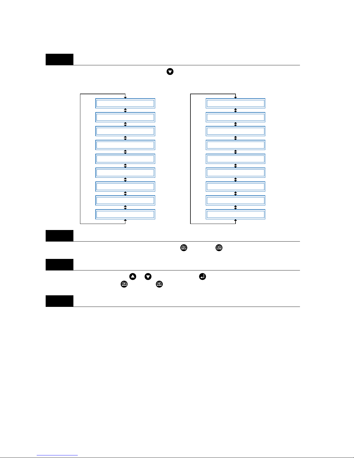
5 – 4
5.2 Setting Special Functions A
Turn on the cutting plotter while holding down the key. The menus for setting the special functions are
displayed.
Scroll up or down to select the required menu using the (NEXT) or (PREV.) key.
Select the setting details using the or key, and press the (ENTER) key to register the setting. To
cancel the selection, press the (NEXT) or (PREV.) key. The next menu is displayed.
Once all the settings have been made, turn off the cutting plotter.
5.3 Description of Special Functions B
These functions are specified only in the special situations described below, and are not normally used.
■ Display Language Setting (MENU LANGUAGE SELECTION)
This function sets the language used on the display. One of six languages can be selected: English,
French, German, Italian, Spanish, or Japanese.
Step
1
Step
2
Step
3
Step
4
":", ";" ENABLED
"W" PEN DOWN
PRIORITY MANUAL
INIT.B 2mm
UP MODE OFF
MEDIA ON
HOME ON
PARALLEL I/F 1
B.W.S. OFF
In GP-GL command mode
MODEL 7550
PRIORITY MANUAL
INIT.B 2mm
UP MODE OFF
MEDIA ON
HOME ON
PARALLEL I/F 1
CIRCLE AUTO
B.W.S. OFF
In HP-GL command mode
Page 99
5 – 5
5.4 Setting Special Functions B
Turn the cutting plotter on while holding down the (ENTER) and (ORIGIN) keys simultaneously.
The special functions B setting menu is displayed.
Use the or key to select the desired display language , and then press the (ENTER) ke y to con-
firm. To cancel the selection, press the (NEXT) or (PREV.) key.
Once all the settings have been made, turn off the cutting plotter.
Step
1
Step
2
Step
3
DISPLAY ENGLISH
Page 100

5 – 6
 Loading...