

Vinyl Express Q60, Q100, Q75, Q160, Q130 User Manual

CUTTING PLOTTER
Vinyl
Express Q60/75/100/130/160
user manual
MANUAL NO. VEXQ06-UM-152
Signwarehouse.com

ii
Table of Contents
TO ENSURE SAFE AND CORRECT USE .............................................................................................vii
Conventions Used in This Manual.........................................................................................................vii
Description of Safety Symbols ..............................................................................................................vii
PREFACE ..................................................................................................................................................xii
Notes on this Manual .............................................................................................................................xii
Registered Trademarks ..........................................................................................................................xii
Copyright ...............................................................................................................................................xii
Special Precautions on Handling Blades ..................................................................................................xiii
Cutting Blades.......................................................................................................................................xiii
Cutter Pens ............................................................................................................................................xiii
After Turning on the Plotter......................................................................................................................xiii
Notes on the Stand ....................................................................................................................................xiv
Machine Caution Label.............................................................................................................................xiv
Daily Maintenance and Storage ................................................................................................................ xiv
Daily Maintenance ................................................................................................................................xiv
Storing the Plotter ................................................................................................................................. xiv
Chapter 1: Out of the Box
1.1 Checking the Contents ....................................................................................................................1-2
1.2 Nomenclature .................................................................................................................................1-3
Front View ...................................................................................................................................1-3
Rear View .....................................................................................................................................1-4
1.3 Assembling the plotter ....................................................................................................................1-5
Vinyl Express Q60/75/100/130/160 (stand provided) .................................................................1-5
Assembling the Stand ................................................................................................................ 1-5
Mounting the stock rollers ...........................................................................................................1-8
1.4 Attaching the Vinyl Express Basket (Option) ................................................................................1-9
1.5 Attaching a Cutter Pen ..................................................................................................................1-10
Attaching a Pen to the Two-Pen Holder (Option) ......................................................................1-11
Attaching a Plotting Pen to the Pen Station ...............................................................................1-12
1.6 Replacing the Cross-Cutter Unit ..................................................................................................1-13
Chapter 2: Cutter Blades and Cutter Pens
2.1 Blade Application and Features ......................................................................................................2-2
2.2 Cutter Pen Nomenclature ...............................................................................................................2-3
2.3 Replacing the Cutter Blade .............................................................................................................2-4
Structure of Cutter Pen .................................................................................................................2-4
Replacing the Cutter Blade ..........................................................................................................2-4
2.4 Adjusting the Blade Length ............................................................................................................2-5
Chapter 3: Preparing to Cut
3.1 Control Panel ..................................................................................................................................3-2
Indicator Lamps ...........................................................................................................................3-2
Function Keys ..............................................................................................................................3-2
Position Keys ...............................................................................................................................3-2
Menu Keys ...................................................................................................................................3-3
3.2 Selecting a Function Menu .............................................................................................................3-4
When the Vinyl Express is in MENU mode ................................................................................3-4

When the power is turned on without any media loaded .............................................................3-5
3.3 Connecting to your Computer ........................................................................................................3-6
3.4 Turning on the Power .....................................................................................................................3-7
3.5 Loading Media ................................................................................................................................3-9
Loading Roll Media (Rear Loading) ............................................................................................3-9
Loading Roll Media (Front Loading) .........................................................................................3-10
Loading Sheet Media .................................................................................................................3-11
3.6 Aligning the Pinch Rollers ...........................................................................................................3-13
Standby Position .........................................................................................................................3-13
When Feeding Long-axis Media (at least 2 meters) ..................................................................3-14
When the Media Width is 100 to 160 mm .................................................................................3-14
When the Media Width is 160 to 540 mm .................................................................................3-14
When the Media Width Exceeds 540 mm ..................................................................................3-15
Changing the Hold-down Force .................................................................................................3-15
Switching between the Strong and Weak settings ................................................................... 3-15
Hold-down Force Assignments................................................................................................ 3-16
3.7 Selecting the Media Type .............................................................................................................3-17
Chapter 4: Pen Setting Conditions
4.1 Pen Conditions ................................................................................................................................4-2
Precautions to observe when cutting high-intensity reflective film........................................... 4-3
How to improve weedability...................................................................................................... 4-3
4.2 Selecting Cutter-Pen Condition Setting Areas ...............................................................................4-4
Selection method........................................................................................................................ 4-4
4.3 Setting the Cutter-pen Conditions ..................................................................................................4-5
To Change the FORCE ................................................................................................................4-5
Setting Procedure ....................................................................................................................... 4-5
To Change the SPEED .................................................................................................................4-5
Setting Procedure ....................................................................................................................... 4-6
To Change the QUALITY ...........................................................................................................4-6
Setting Procedure ....................................................................................................................... 4-6
To Change the OFFSET ...............................................................................................................4-7
Setting Procedure ....................................................................................................................... 4-7
4.4 Running Cutting Tests ....................................................................................................................4-8
Test Cutting Procedure ............................................................................................................. 4-8
4.5 Adjusting the Blade Length ..........................................................................................................4-10
Test Cutting Procedure ............................................................................................................ 4-10
iii
Chapter 5: BASIC FUNCTIONS AND OPERATIONS
5.1 Using the HOLD Function .............................................................................................................5-2
Setting Procedure ....................................................................................................................... 5-2
5.2 Withdrawing the Pen Carriage .......................................................................................................5-3
Setting Procedure ....................................................................................................................... 5-3
5.3 Moving the Pen Carriage to the Origin Point .................................................................................5-3
Setting Procedure ....................................................................................................................... 5-3
5.4 Using the PRE FEED Function ......................................................................................................5-4
Setting Procedure ....................................................................................................................... 5-4
5.5 Moving the Origin Point .................................................................................................................5-5
Setting Procedure ....................................................................................................................... 5-5
When the origin is moved after the coordinate axes were rotated ...............................................5-5
When the coordinate axes are rotated after moving the origin point ...........................................5-6
5.6 Using the COPY Function ..............................................................................................................5-7
Setting Procedure ....................................................................................................................... 5-7

iv
5.7 Pen Up/Down ..............................................................................................................................5-10
Setting Procedure ..................................................................................................................... 5-10
5.8 Using the CROSS-CUT Function ................................................................................................5-11
Cutting position........................................................................................................................ 5-11
Cutting width ........................................................................................................................... 5-11
Guidelines for replacing the cross-cutting unit........................................................................ 5-11
Auto Cross-cutting .....................................................................................................................5-11
Manual Cross-cutting .................................................................................................................5-12
Setting Procedure ..................................................................................................................... 5-12
5.9 Using the MOVE STEP Function ...............................................................................................5-13
Setting Procedure ..................................................................................................................... 5-13
5.10 Upon detection of no medium during roll media cutting .............................................................5-14
Setting Operation ..................................................................................................................... 5-14
Chapter 6: ADVANCED FUNCTIONS AND OPERATIONS
6.1 Changing the Initial Feed Speed ..................................................................................................... 6-2
Setting Procedure ....................................................................................................................... 6-2
6.2 Setting AUTO PRE FEED .............................................................................................................6-3
Making the setting at the INITIAL MENU screen .................................................................... 6-3
Making the setting at the FUNCTION 2 screen ........................................................................ 6-4
6.3 Setting the ORIGIN in HP-GL™ Mode ........................................................................................6-5
Setting Procedure ....................................................................................................................... 6-5
6.4 Setting the Cutting/Plotting Area ...................................................................................................6-6
Setting Procedure ....................................................................................................................... 6-6
6.5 Expanding the Cutting/Plotting Area .............................................................................................6-9
Setting Procedure ....................................................................................................................... 6-9
6.6 Setting the PAGE LENGTH ........................................................................................................6-11
Setting Operation ..................................................................................................................... 6-11
6.7 Rotating the Coordinate Axes ......................................................................................................6-13
6.8 Setting the Mirror Mode ...............................................................................................................6-14
Setting Procedure ..................................................................................................................... 6-14
6.9 Enlarging or Reducing an Image ..................................................................................................6-15
Setting Procedure ..................................................................................................................... 6-15
6.10 Data Sorting Settings ....................................................................................................................6-16
Setting Procedure ..................................................................................................................... 6-16
6.11 Auto Registration Mark Reading Function (Option) ....................................................................6-17
The registration mark pattern .....................................................................................................6-17
The reading area required for registration mark detection .........................................................6-18
The registration mark locations .................................................................................................. 6-18
The position of the origin point ..................................................................................................6-19
Media on which registration marks cannot be detected .............................................................6-20
If registration marks cannot be automatically recognized ......................................................... 6-20
6.12 Setting the Registration Mark Mode (Option) ..............................................................................6-21
Setting Procedure ..................................................................................................................... 6-21
2-point reading (2POINTS) ........................................................................................................6-22
3-point reading (3POINTS) ........................................................................................................6-23
4-point reading (4POINTS) ........................................................................................................6-25
6.13 Setting the Registration Mark Reading Area (Option) .................................................................6-27
Setting Procedure ..................................................................................................................... 6-27
6.14 Selecting the Registration MARK TYPE (Option) ......................................................................6-29
Setting Procedure ..................................................................................................................... 6-29
6.15 Specifying the Registration MARK SIZE (Option) .....................................................................6-30
Setting Procedure ..................................................................................................................... 6-30

6.16 Setting the DISTANCE ADJUSTMENT (Option) ......................................................................6-31
Setting Procedure ..................................................................................................................... 6-31
6.17 Setting the AXIS ORIGIN OFFSET (Option) .............................................................................6-33
Setting Procedure ..................................................................................................................... 6-33
6.18 Setting the PAPER-WEIGHT Function (Option) ........................................................................6-35
Setting Procedure ..................................................................................................................... 6-35
6.19 Setting the SENSOR ADJUSTMENT Function ..........................................................................6-37
Setting Operation ..................................................................................................................... 6-37
6.20 Setting the SENSOR OFFSET ADJUSTMENT (Method 1) (Option) ........................................6-39
Setting Procedure ..................................................................................................................... 6-39
6.21 Setting the AXIS OFFSET ADJUSTMENT (Method 2) (Option) ..............................................6-41
Setting Procedure ..................................................................................................................... 6-41
6.22 Selecting the Axis Alignment Method .........................................................................................6-43
Selecting the Axis Alignment Method..................................................................................... 6-43
6.23 Selecting the Axis Alignment Tool ..............................................................................................6-44
Selecting the Axis Alignment Tool.......................................................................................... 6-44
6.24 AXIS ALIGNMENT Settings ......................................................................................................6-45
Selecting an Axis Alignment Method ........................................................................................6-45
2-point method ......................................................................................................................... 6-45
3-point method ......................................................................................................................... 6-46
4-point method ......................................................................................................................... 6-48
6.25 Setting Tangential Emulation .......................................................................................................6-50
Selecting the tangential emulation mode ................................................................................. 6-50
Enabling/Disabling Tangential Emulation............................................................................... 6-51
Setting Overcut ........................................................................................................................ 6-52
6.26 Setting the PEN UP SPEED .........................................................................................................6-53
Setting Procedure ..................................................................................................................... 6-53
6.27 Adjusting the Blade OFFSET ANGLE ........................................................................................6-54
Setting Procedure ..................................................................................................................... 6-54
6.28 Setting the OFFSET FORCE ........................................................................................................6-55
Setting Procedure ..................................................................................................................... 6-55
6.29 Setting the STEP PASS ................................................................................................................6-56
Setting Procedure ..................................................................................................................... 6-56
6.30 Setting the INTIAL DOWN FORCE ...........................................................................................6-57
Setting Procedure ..................................................................................................................... 6-57
6.31 Setting the DISTANCE ADJUST Function .................................................................................6-58
Setting Procedure ..................................................................................................................... 6-58
Setting the Distance Adjust Parameter .................................................................................... 6-59
6.32 Selecting the Type of Perforated Line ..........................................................................................6-60
Setting Operation ..................................................................................................................... 6-60
v
Chapter 7: OPTIONS
7.1 Loupe (PHP61-LOUPE) .................................................................................................................7-2
Axis Alighment and plotting Area Adjustment ...........................................................................7-2
Attaching the Loupe .....................................................................................................................7-2
Using the Loupe ...........................................................................................................................7-3
7.2 Pouncing Tool ................................................................................................................................7-4
Attaching the Pouncing Tool .......................................................................................................7-4
Holder for auto registration mark sensor ........................................................................7-5
Setting Procedure ....................................................................................................................... 7-5
7.3 Pen Assignment (for 2-pen models only) .......................................................................................7-6
Setting Procedure ....................................................................................................................... 7-6

vi
7.4 Pen Offset (for 2-pen models only) ................................................................................................7-7
Setting Procedure ....................................................................................................................... 7-7
Chapter 8: BACK GROUND SETTINGS
8.1 Description of the Background Settings .........................................................................................8-2
8.2 Setting the Background Settings ....................................................................................................8-5
Setting Procedure ....................................................................................................................... 8-5
Chapter 9: TEST MODES AND TROUBLESHOOTING
9.1 Using the Condition List Mode ......................................................................................................9-2
Setting Procedure ....................................................................................................................... 9-2
9.2 Using the DATA DUMP mode ......................................................................................................9-3
Setting Procedure ....................................................................................................................... 9-3
9.3 The Plotter Does Not Operate When Turned On ...........................................................................9-4
9.4 The Plotter Does Not Operate Correctly ........................................................................................9-5
9.5 The Cutting Results Are Unsatisfactory .........................................................................................9-8
9.6 Error Messages in GP-GL Command Mode ................................................................................9-10
9.7 Error Messages in HP-GL Command Mode ................................................................................9-11
CAUSE .................................................................................................................................... 9-11
SOLUTION.............................................................................................................................. 9-11
Chapter 10: INTERFACES
10.1 RS-232C Interface ........................................................................................................................10-2
Factory Preset Settings............................................................................................................. 10-2
10.2 USB Interface Settings .................................................................................................................10-3
Supported Operating Systems.................................................................................................. 10-3
10.3 Interface Setting Menu .................................................................................................................10-4
Using the INITIAL MENU to set the functions ...................................................................... 10-4
Using the MENU MODE to set the functions ......................................................................... 10-4
10.4 Setting the STEP SIZE .................................................................................................................10-5
Setting Procedure ..................................................................................................................... 10-5
10.5 Setting the RS-232C Interface Transmission Conditions ............................................................. 10-6
Setting Procedure ..................................................................................................................... 10-6
10.6 COMMAND Settings ...................................................................................................................10-7
Setting Procedure ..................................................................................................................... 10-7
Chapter 11: Specifications
11.1 Main Specifications ......................................................................................................................11-2
11.2 Options .........................................................................................................................................11-3
11.3 Supplies ........................................................................................................................................11-3
11.4 Menu Tree ....................................................................................................................................11-4
11.5 External Dimensions ....................................................................................................................11-5
Vinyl Express Q60/75/100/130/160 ...........................................................................................11-5

vii
DANGER
WARNING
CAUTION
TO ENSURE SAFE AND CORRECT USE
• To ensure the safe and correct use of your plotter, read this manual thoroughly prior to use.
• After reading this manual, keep it in a handy location for quick reference as necessary.
• Do not allow small children to touch the plotter.
• The following describes important points for safe operation. Be sure to observe them strictly.
Conventions Used in This Manual
To ensure the safe and accurate use of the plotter as well as to prevent human injury and property damage, the safety
precautions provided in this manual are ranked in the three categories described below. Be sure to gain a full understanding of the difference between each of the categories before reading the Manual.
: This category provides information that, if ignored, is highly likely to cause fatal or serious
injury to the operator.
: This category provides information that, if ignored, is likely to cause fatal or serious injury
to the operator.
: This category provides information that, if ignored, could cause injury to the operator or
damage to the plotter.
Description of Safety Symbols
The symbol indicates information that requires careful attention (including warnings). The specific point
requiring attention is described by an illustration or text within or next to the symbol.
The symbol indicates an action that is prohibited. Such prohibited action is described by an illustration
or text within or next to the symbol.
The symbol indicates an action that must be performed. Such imperative action is described by an
illustration or text within or next to the symbol.
viii
Specified
rating
Safety Precautions
WARNING
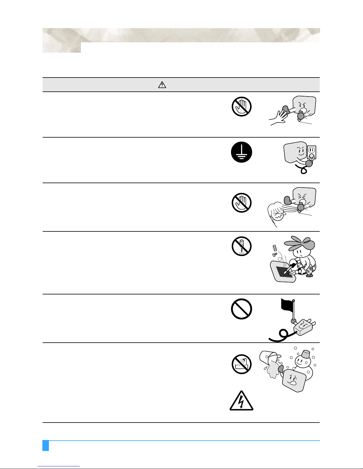
Do not touch the rollers or moving parts such as the carriage
while cutting or plotting is in progress.
• Such action may result in injury.
Be sure to ground the earth terminal.
• If the plotter is not grounded, the operator could suffer an electric
shock in the event of current leakage.
Keep your hands, hair, etc., away from the rollers or moving
parts such as the carriage even if the plotter is stopped, as it
may suddenly start moving when data is received.
• Such action may result in injury.
Do not touch
Ground the plotter
Keep your distance
Do not disassemble, repair, or remodel the plotter.
• Such action may cause electric shock or a fire hazard due to current
leakage.
• Contact with the high-voltage parts within the plotter may cause electric shock.
• If the plotter requires repairs, contact your sales representative or
nearest Signwarehouse vendor.
Do not connect the plotter to a non-rated power supply.
• Use of a different supply voltage may result in electric shock or a fire
hazard due to current leakage.
Do not use the plotter in a location where it will be exposed to
water, rain, or snow.
• Such locations may cause electric shock or a fire hazard due to current leakage.
No disassembly
Prohibited
Avoid water
Beware of electric shock
Safety Precautions (Continued)
WARNING
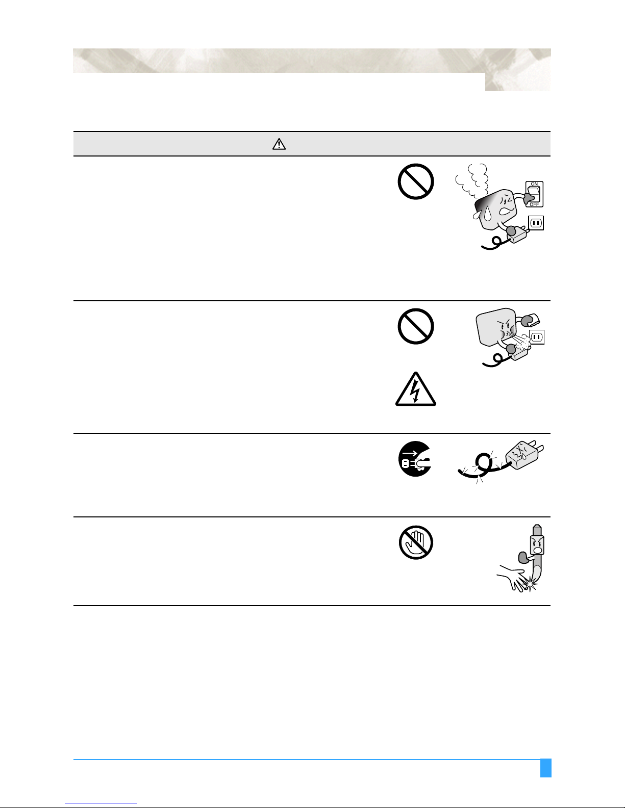
If the plotter generates smoke, overheats, emits a strange
odor, or otherwise functions abnormally, do not continue
using it. Turn off the power and unplug the power cord from
the electrical socket.
• Use of the plotter in such a condition may result in a fire hazard or
electric shock.
• After confirming that smoke is no longer being emitted, contact your
sales representative or nearest Signwarehouse vendor for repairs.
• Never attempt to perform repairs yourself. Repair work by inexperienced personnel is extremely dangerous.
Do not allow dust or metal scraps to adhere to the power
plug.
• A dirty power plug may result in electric shock or a fire hazard due to
current leakage.
ix
Prohibited
Prohibited
Do not use the power cord if it is damaged.
• Use of a damaged cord may result in electric shock or a fire hazard
due to current leakage.
• Replace the power cord with a new one.
Be careful when handling the cutter blade.
• Touching the blade with your bare hand may cause injury.
• Do not touch the cutter blade while cutting is in progress.
Beware of electric shock
Unplug the power
cord from the socket
Do not touch
x
Safety Precautions (Continued)
CAUTION
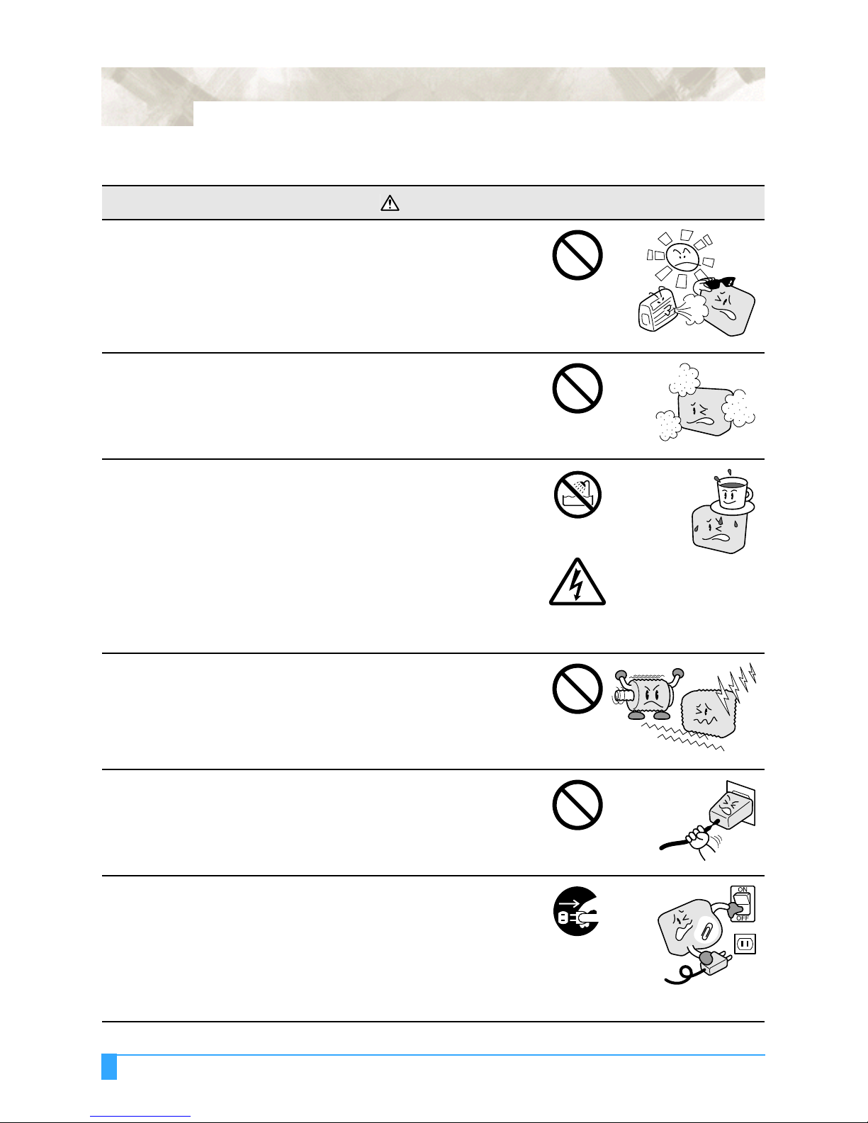
Do not use or store the plotter in a location exposed to direct
sunlight or the direct draft of an air conditioner or heater.
• Such locations may impair the performance of the plotter.
Do not use the plotter in an excessively dusty or humid
location.
• Such locations may impair the performance of the plotter.
Do not place any receptacle containing water or other fluid on
top of the plotter.
• Fluid falling inside the plotter may cause electric shock or a fire hazard due to current leakage.
Prohibited
Prohibited
Avoid water
Beware of electric shock
Do not use the plotter in a location subject to excessive
mechanical vibration or electrical noise.
• Use in such locations may impair the performance of the plotter.
When disconnecting the power cord or interface cable, do not
pull on the cord/cable.
• Such action will damage the cord/cable, resulting in a fire hazard or
electric shock.
If water or foreign matter enters the plotter, discontinue use.
Turn off the power and unplug the power cord from the
electrical socket.
• Use of the plotter in such a condition may result in electric shock or a
fire hazard due to current leakage.
• Contact your sales representative or nearest Signwarehouse vendor
for repairs.
Prohibited
Prohibited
Unplug the power
cord from the socket
Safety Precautions (Continued)
CAUTION
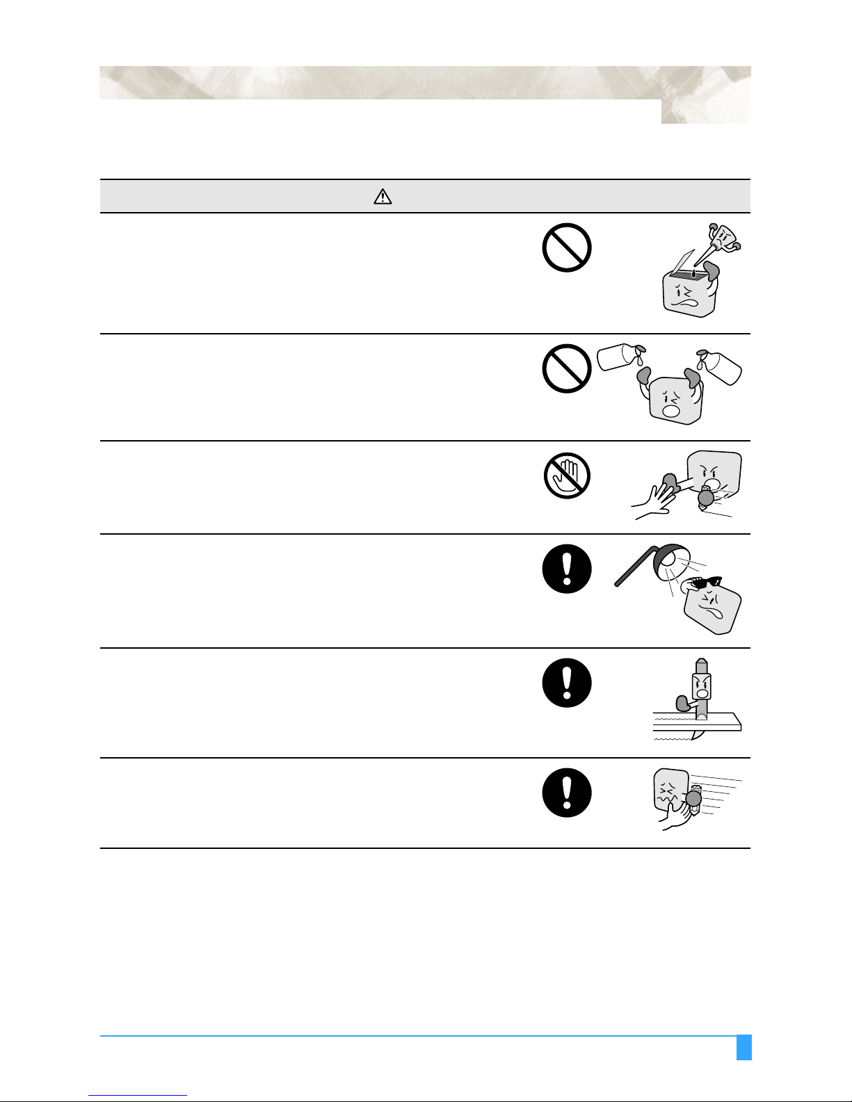
Do not attempt to lubricate the cutting-plotter mechanisms.
• Such action may cause it to break down.
Do not clean the plotter using volatile solvents such as
thinner or benzene.
• Such action may impair its performance.
Provide sufficient space around the plotter so that it does not
strike any objects in its vicinity during cutting or plotting.
• Such contact may cause misalignment in cutting or plotting.
Prohibited
Prohibited
Do not touch
xi
T
h
i
n
n
e
r
e
n
e
z
n
e
B
When using indoor lighting such as fluorescent or other
electrical lamps, provide a distance of at least one meter
between the plotter and the light source.
• Close proximity of such a light source may cause the sensor to malfunction and prevent proper size detection of the media.
When using the cutter, take care not to extend the blade more
than necessary.
• An overly extended blade will damage the cutting mat and adversely
affect the cutting quality.
Move the pen carriage slowly when moving it manually in
order to load the medium or for other reasons.
• Moving it quickly may damage the plotter.

xii
PREFACE
Thank you for choosing a Signwarehouse Vinyl Express Series plotter. The Vinyl Express Series plotters employ a digital servo drive system to achieve high-speed and high-precision cutting. In addition to cutting marking film and othereop media, an Vinyl Express series plotter can also be used as a pen plotter. To ensure high cutting quality and
optimal productivity, be sure to read this User's Manual thoroughly prior to use.
Notes on this Manual
(1) No part of this publication may be reproduced, stored in a retrieval system, or transmitted, in any form or by any
means, without the prior written permission of Signwarehouse.com.
(2) The product specifications and other information in this manual are subject to change without notice.
(3) While every effort has been made to provide complete and accurate information, please contact your sales repre-
sentative or nearest Signwarehouse vendor if you find any unclear or erroneous information or wish to make
other comments or suggestions.
(4) Notwithstanding the stipulations in the preceding paragraph, Signwarehouse.com assumes no liability for dam-
ages resulting from either the use of the information contained herein or the use of the product.
Registered Trademarks
All names of companies, brands, logotypes, and products appearing in this manual are the trademarks or registered
trademarks of their respective companies.
Copyright
This User’s Manual is copyrighted by Signwarehouse.com.
xiii
Special Precautions on Handling Blades
Sharp cutter blades are used with this plotter. Handle the cutter blades and holders with care to prevent bodily injury.
Cutting Blades
Cutter blades are very sharp. While handling a cutter blade or cutter pen, be careful to avoid cutting your fingers or
other parts of your body.
Promptly return used blades to the cutter case provided. When the case is completely filled, discard the used blades
together with the case.
Cutter Pens
The tip consists of a sharp blade. Be sure not to extend it too far. Moreover, when you are not using the cutter pen,
make sure that the blade is fully retracted.
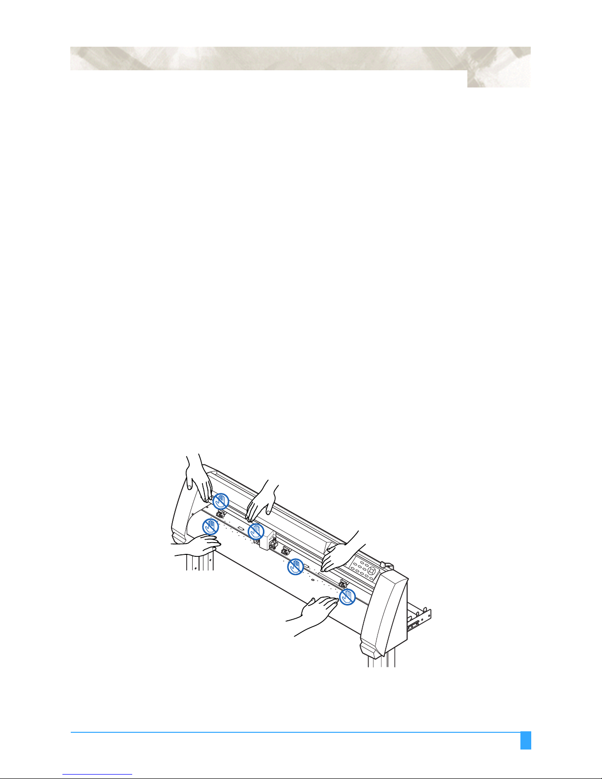
After Turning on the Plotter
During the course of turning on the plotter, be sure to observe the following precautions. The pen carriage and loaded
media may suddenly move during the cutting operation, immediately afterward and when setting the plotter's functions.
Keep hands, hair, clothing and other objects out of the vicinity of the pen carriage, grit rollers and loaded media. To prevent operator injury and poor cutting results, be careful not to allow hands, hair, clothing or other foreign objects to
become entangled with the pen carriage or loaded media while the plotter is operating.
.
xiv
Notes on the Stand
Be sure to use only the stand designed for the Vinyl Express Series with your Vinyl Express Series plotter. The use of
a different stand may cause a plotter malfunction or bodily injury.
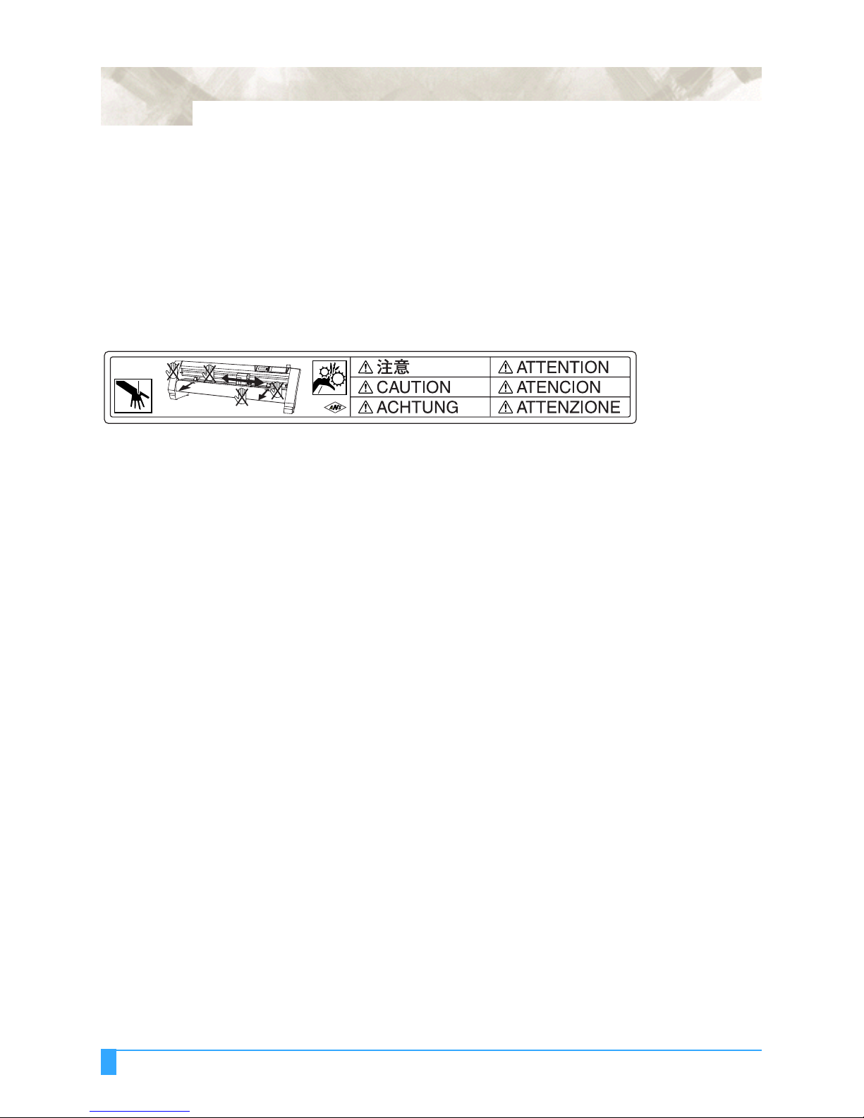
Machine Caution Label
The machine's Caution Label is located on the top cover. Be sure to observe all the cautions on the label.
Daily Maintenance and Storage
Daily Maintenance
During the course of daily plotter operation, be sure to observe the following precautions:
(1) Never lubricate the mechanisms of the plotter.
(2) Clean the plotter's casing using a dry cloth that has been moistened in a neutral detergent diluted with water.
Never use thinner, benzene, alcohol, or similar solvents to clean the casings; they will damage the casing's finish.
(3) Clean the cutting mat using a dry cloth. In case of stubborn stains, use a cloth that has been moistened in alcohol
or in a neutral detergent diluted with water.
(4) Clean the plotter's paper sensors using a cloth moistened in a neutral detergent diluted with water. Never use thin-
ner, benzene, alcohol, or similar solvents to clean the sensors; cleaners such as these will damage the sensors.
Storing the Plotter
When your plotter is not in use, be sure to observe the following points:
(1) Remove the pen attached to the penholder
(2) Cover the plotter with a cloth to protect it from dust and dirt
(3) Do not store the plotter in direct sunlight or in high temperatures

Chapter 1: Out of the Box
This chapter describes plotter nomenclature and how to
install your plotter.
Topics in this chapter
1.1 Checking the Contents
1.2 Nomenclature
1.3 Assembling the plotter
1.4 Attaching the Vinyl Express Basket (Option)
1.5 Attaching a Cutter Pen
1.6 Replacing the Cross-Cutter Unit
1 - 2
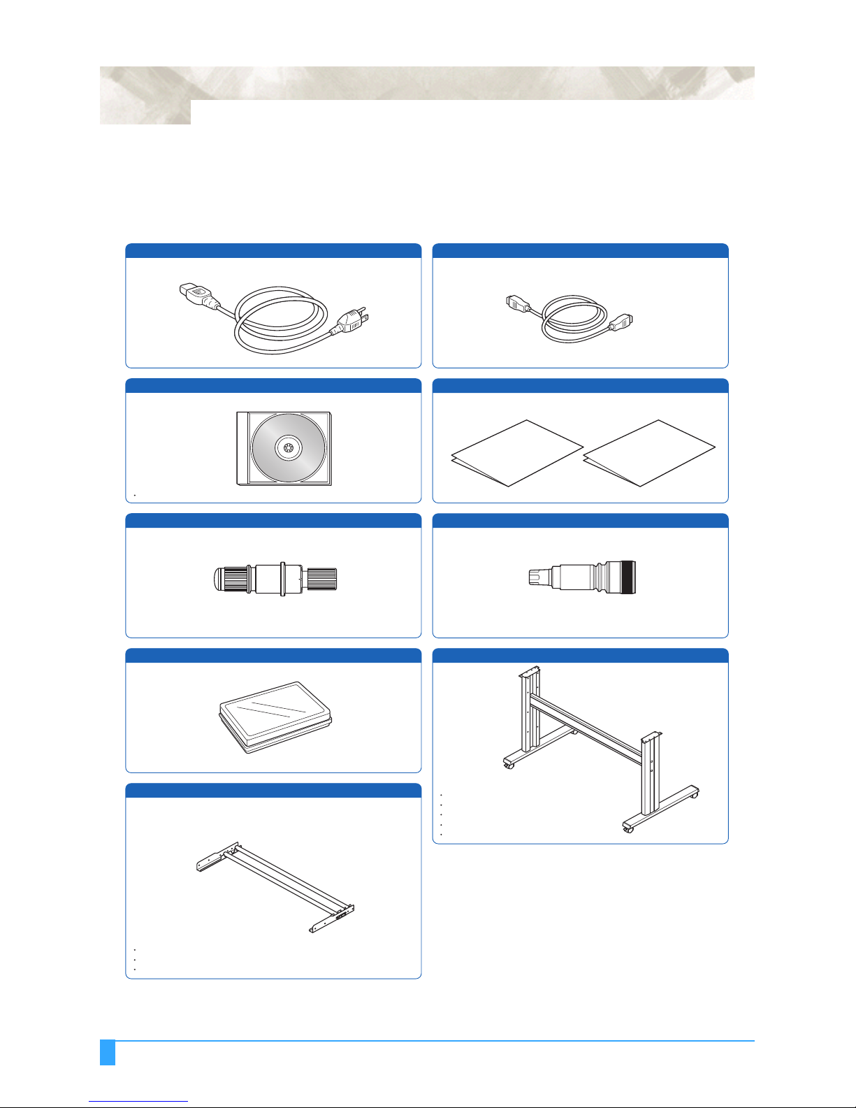
1.1 Checking the Contents
After unpacking your plotter, check that all of the standard accessories shown
below are present. If any accessory is missing, contact your sales representative
or the nearest Signwarehouse dealer.
AC power cord
1 1 each
USB cable (3-m length)
User Guide CD-ROM
1
Contains:
User's Manual (pdf)
Windows driver
Cutter holder
(PHP32-CB09N)
1
Cutter blades
1
Media bracket
1
Quick Start Manual, Usage Precautions
1 of each
Water-based fibertip pen
1
Stand
1
Base assembly x 2
Stand side bar x 2
Center bar x 1
Socket head cap screw x 20
Allen wrench x 1
Media stocker x 2
Stock roller x 2
M4 binding head screws x 8
Out of the Box: Checking the Contents
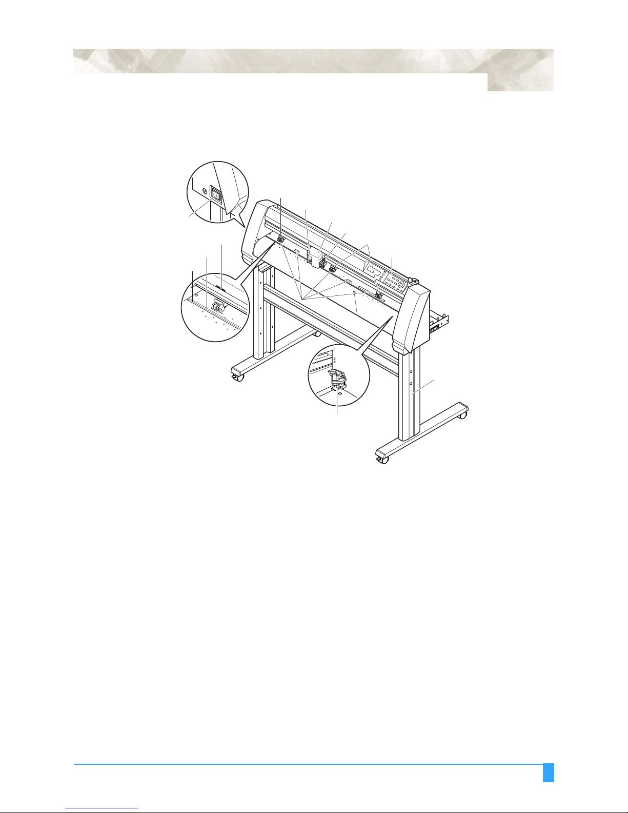
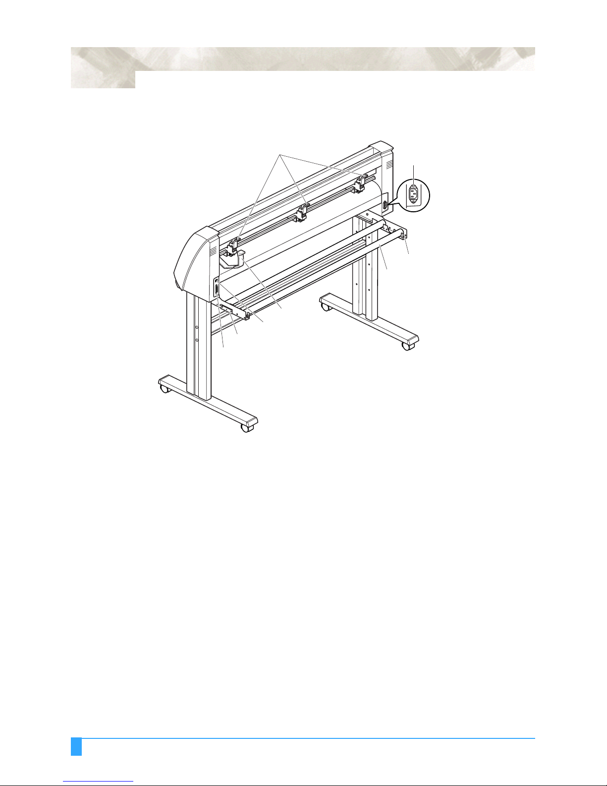
1.2 Nomenclature
Grit roller
Media sensor
Front View
Power switch
Grit roller position guide
Cutting mat
Cutting groove
1 - 3
Pinch roller
Cross-cutter unit
Pen carriage
Pen holder
Pinch rollers
Control panel
Grit roller
Media sensor
Stand
Pen station
Power switch: ..............Used to turn the plotter on and off.
Control panel: ..............Used to access various plotter functions.
Pinch rollers: ...............Rollers that push the media against the grit rollers.
Grit rollers: ..................Metallic rollers with a file-like surface that feed the media
back and forth.
Media sensors: ............The front sensor is used to sense the leading edge of the
media. The rear sensor is used to sense the trailing edge
of the media.
Pen carriage: ...............Moves the cutter-pen or plotting pen across the media
during cutting or plotting.
Pen holder: ..................Holds the cutter-pen or plotting pen and moves it up or
down.
Pen station (installed on 2-pen models only: option):
The second pen is mounted here.
Stand: .........................Used to make the plotter more portable and to free up
counter space
Grit roller position guide:
Stickers on the front of the Y rail and the rear side of the
top cover that show the position of each grit roller. Use
these alignment marks as an aid in locating the pinch roll-
ers.
Cutting groove: ............Used when cross-cutting is performed.
Cross-cutter unit: .........Used to perform cross-cutting of media so that the cut
length can be removed from the roll.
Out of the Box: Nomenclature
1 - 4
Rear View
Pinch roller hold-down force switching lever
AC line inlet
Media stocker
Stock rollers
Media set lever
USB interface connector
Media lock
RS-232C interface connector
Media set lever: ...........Used to raise or lower the pinch rollers during the loading
or unloading of media.
Pinch roller hold-down force switching lever:
Used to switch between the two pinch roller forces (strong
and weak).
AC line inlet: ................Inlet where the power cord is connected.
Media stocker: .............Used to carry roll media and ensure its proper rotation.
Stock rollers: ...............A media roll is placed on these rollers.
Media lock: ..................Used to prevent the stock rollers from rotating when the
media roll has been placed on top of them. The media
lock ensures that the media is pulled straight out from the
roll.
USB interface connector:
Used to connect the plotter to the computer with a USB
interface cable.
Serial interface connector:
Used to connect the plotter to the computer with an RS-
232 serial interface cable.
Out of the Box: Nomenclature
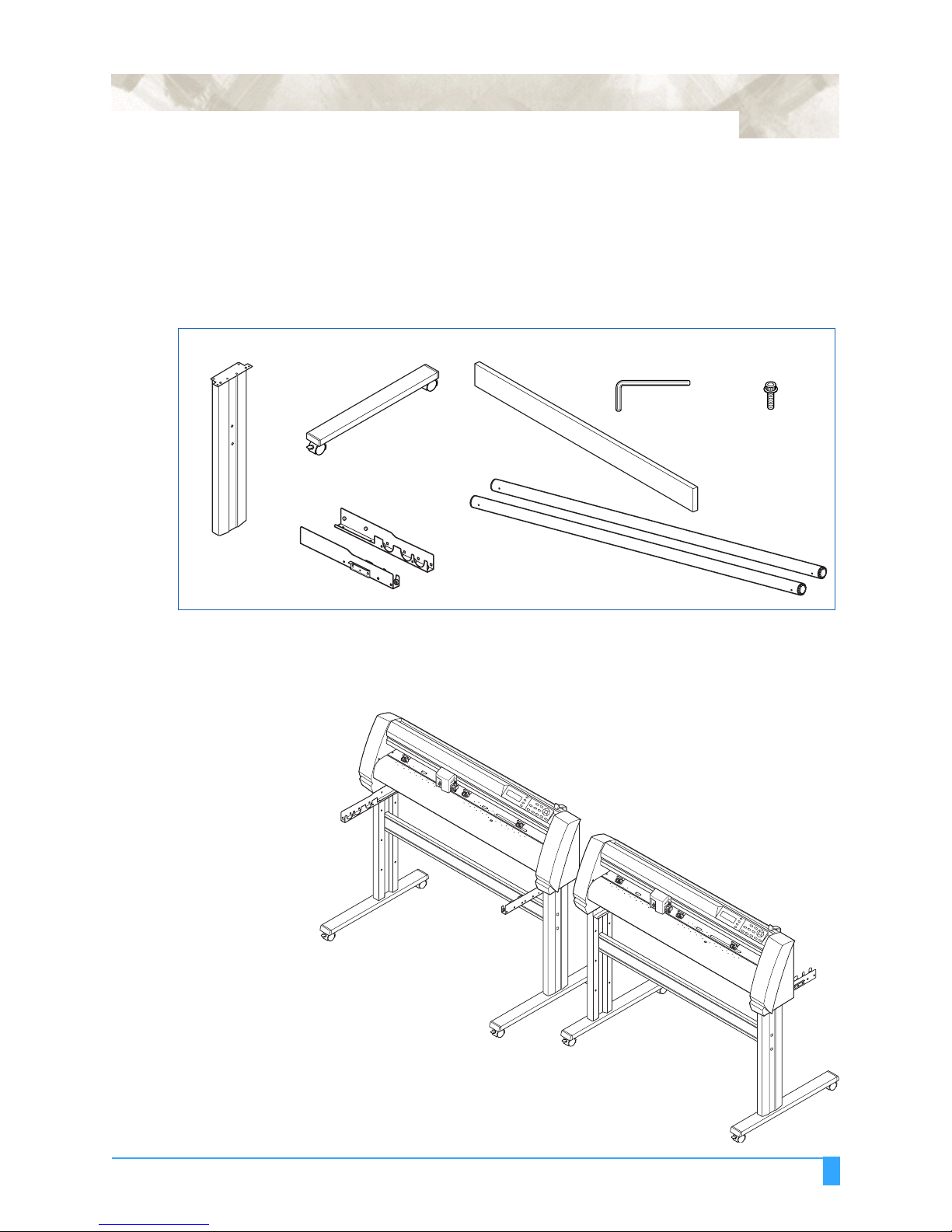
1.3 Assembling the plotter
Vinyl Express Q60/75/100/130/160 (stand provided)
Assemble the stand, attach the media bracket to the stand, and then mount the
plotter on the stand.
The stand and the media bracket are made up of the following parts.
1 - 5
Base assembly x 2 Allen wrench
Media stocker x 2
Center bar x 1Stand side bar x 2 Socket head cap screw
Stock roller x 2
(for M5 screws) x 1
(M5) x 20
ASSEMBLING THE STAND
The mounting direction is different for the front loading and the rear loading
models.
<Front loading>
<Rear loading>
Out of the Box: Assembling the plotter
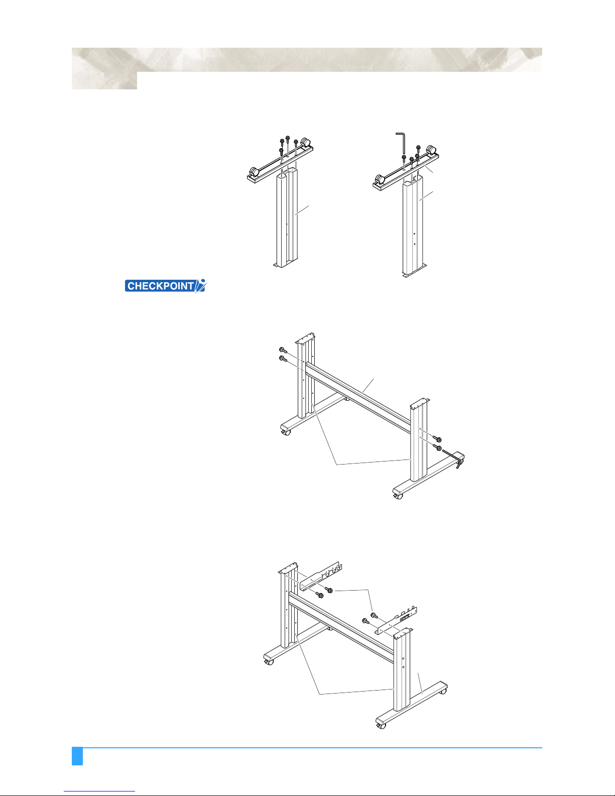
1 - 6
1 Assemble the left and right stand sides. Fasten a base assembly to each of the
stand side bars with four socket head cap screws, using the Allen wrench.
Socket head
cap screws
Base assembly
Stand side bar
Stand side bar
Assemble the stand so that the front and rear lengths of the base assembly are
the same for both the left and right stand sides.
2 Loosely fasten the center bar to the left and right stand sides with four socket
head cap screws (two on each side), using the Allen wrench.
Socket head
cap screws
Center bar
Socket head
cap screws
Stand sides
3 Attach a media stocker to each of the left and right stand sides with two socket
head cap screws, using the Allen wrench. Mount the media stockers so that
each one protrudes directly above the longer of the two base assembly
lengths.
Media stocker
Socket head cap screws
Media stocker
Out of the Box: Assembling the plotter
Base assembly
Stand sides
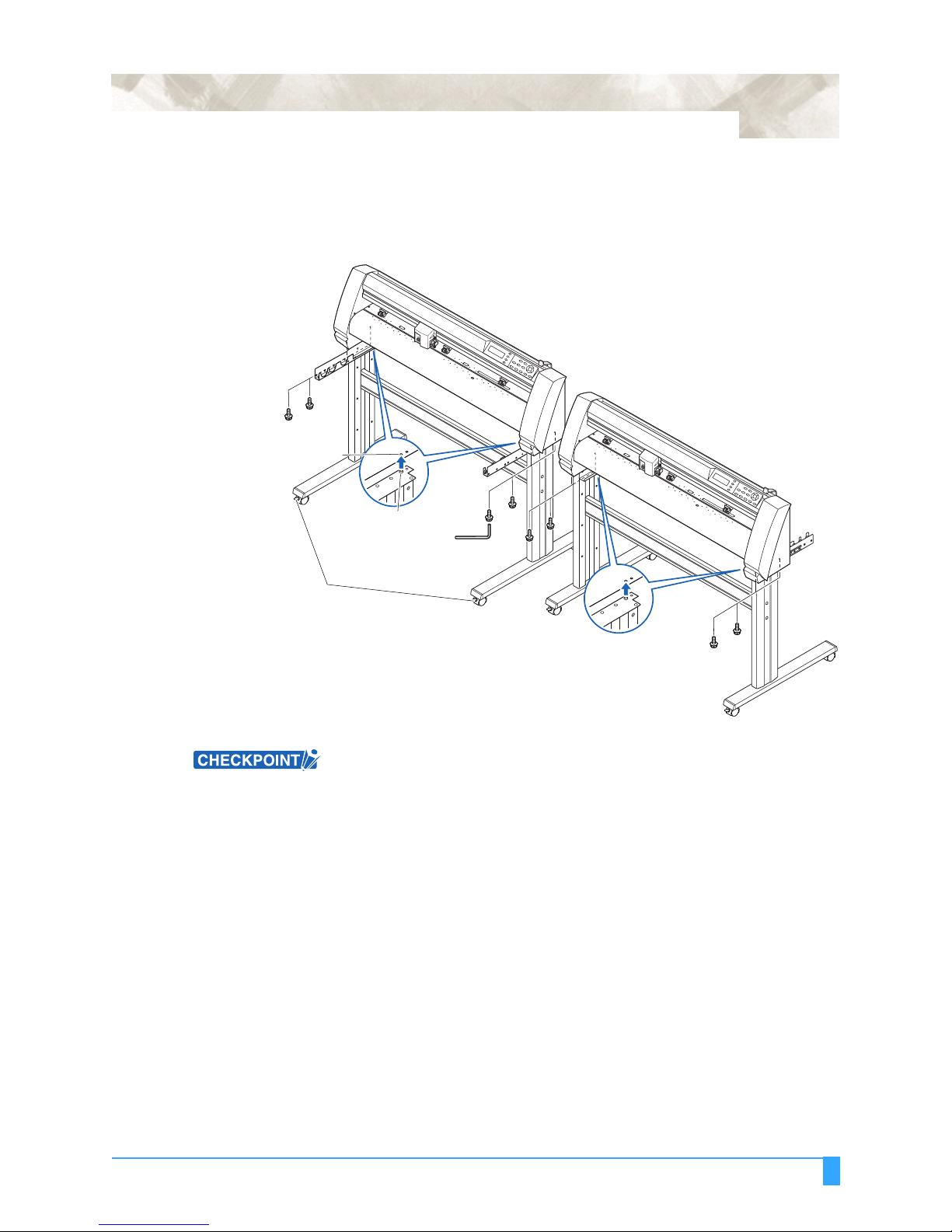
1 - 7
4 Mount the plotter on the stand by inserting the positioning pins on the stand
into the positioning holes on the underside of the plotter. Fasten with four
socket head cap screws (two on each side), using the Allen wrench.The cutting
plotter mounting direction is different for the front loading and the rear loading
models.
<Front loading>
Socket head
cap screws
Positioning pin hole
<Rear loading>
Socket head
Positioning pin
Caster stoppers
cap screws
5 Tighten the socket head cap screws loosely fastened in Step 2.
• Check that all of the screws used for fastening have been tightened. The media
may not be fed correctly if even one of the screws is loose.
• When installing the plotter, make sure that there are no objects in its vicinity.
Leave a clear space of at least 300 mm around the plotter.
Out of the Box: Assembling the plotter
1 - 8
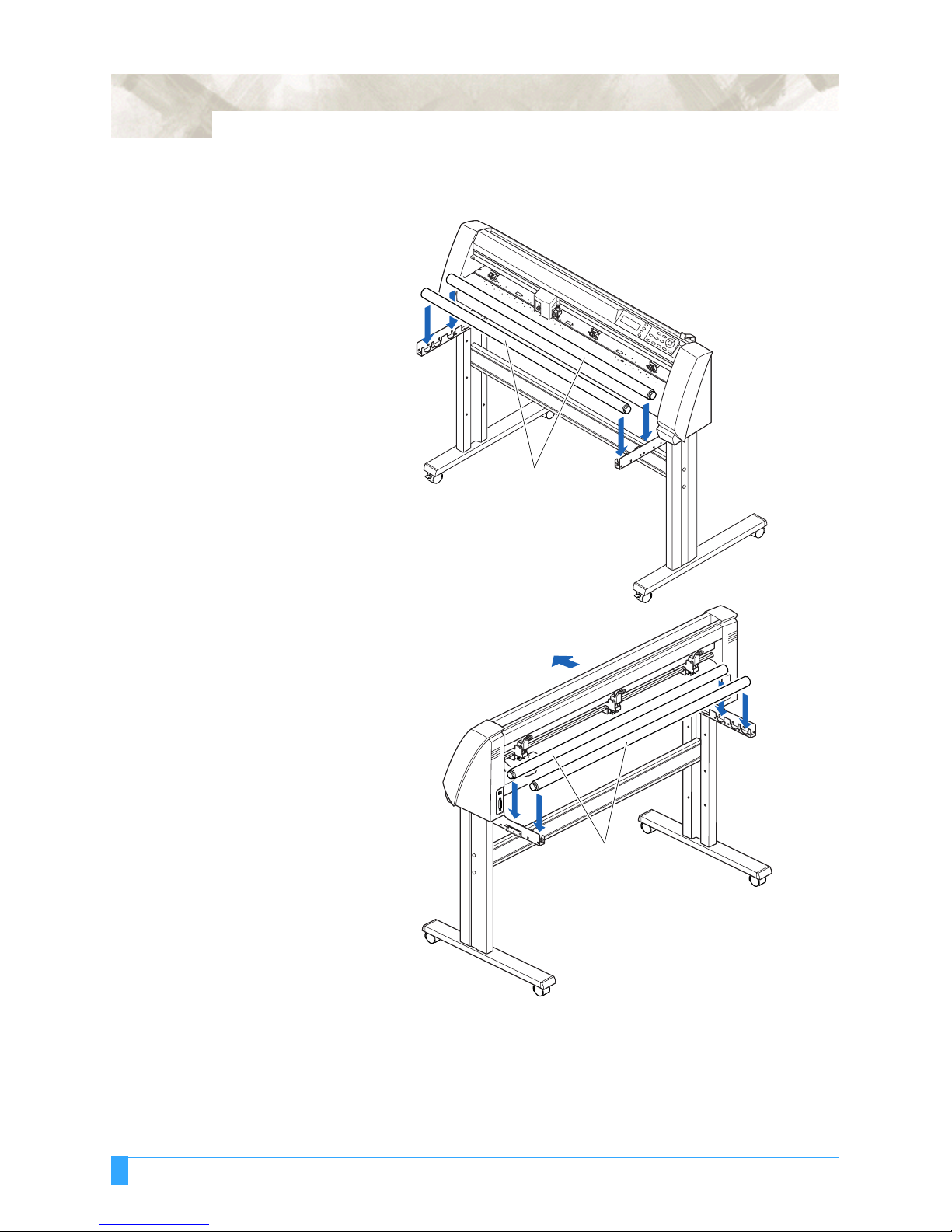
Mounting the stock rollers
Insert the stock rollers into the slots on the media stocker.
<Front loading>
Stock rollers
<Rear loading>
Front
Stock rollers
Out of the Box: Assembling the plotter
1 - 9
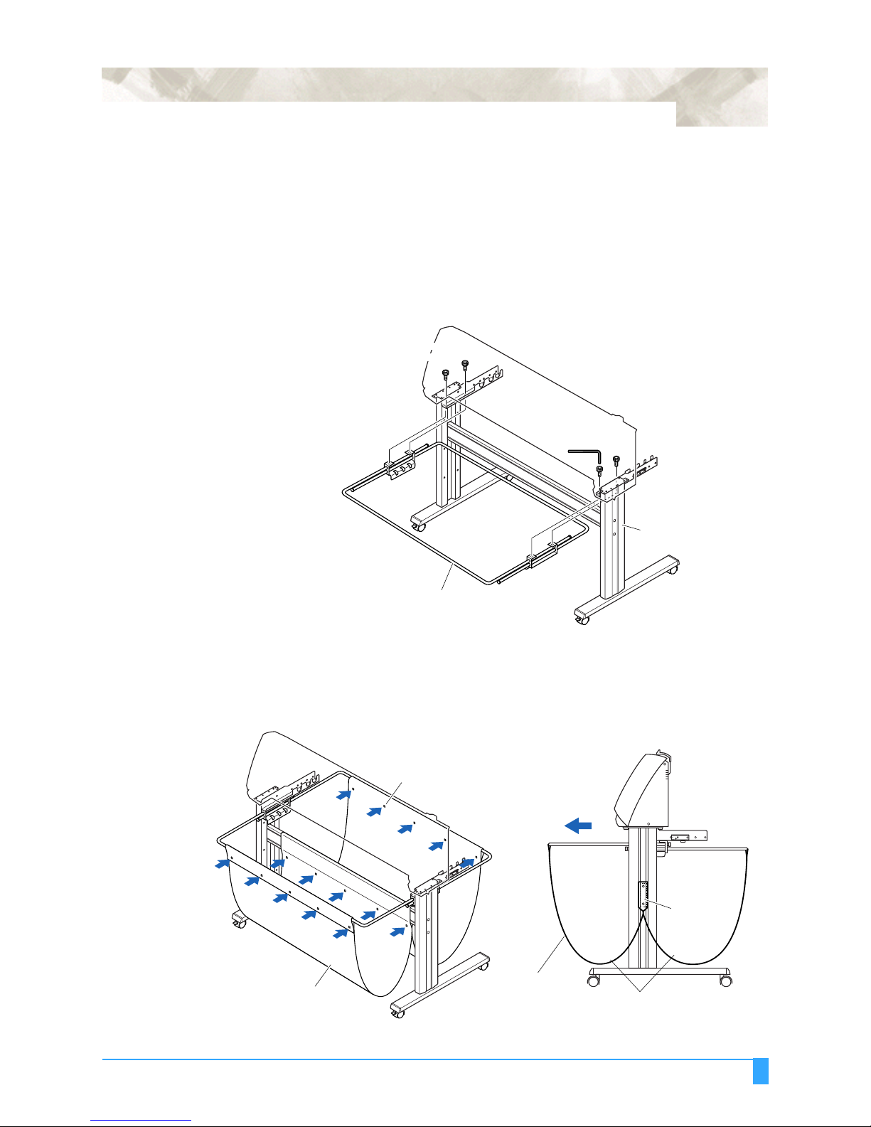
1.4 Attaching the Vinyl Express Basket (Option)
The Vinyl Express Basket box contains one basket holder assembly (one front
basket tube and one rear basket tube inserted into two tube brackets), one cloth
basket, and a screw/wrench set.
1 Attach one of the two tube brackets on the basket holder assembly to the left
side of the stand with two socket head cap screws, using the Allen wrench.
Repeat this step with the other side.
Socket head
cap screw
Socket head
cap screw
Stand
Basket holder assembly
2 Drape the middle section of the cloth basket over the stand's center bar, and
then snap the middle section of the cloth basket around the center bar. Snap
the front edge of the cloth basket around the front basket tube, and then snap
the rear edge of the cloth basket around the rear basket tube.
Side view
Holder snap
Front
Center bar
Cloth basket
Cloth basket
Separate into front and rear baskets,
with the center bar as the center point
Out of the Box: Attaching the Vinyl Express Basket (Option)
1 - 10
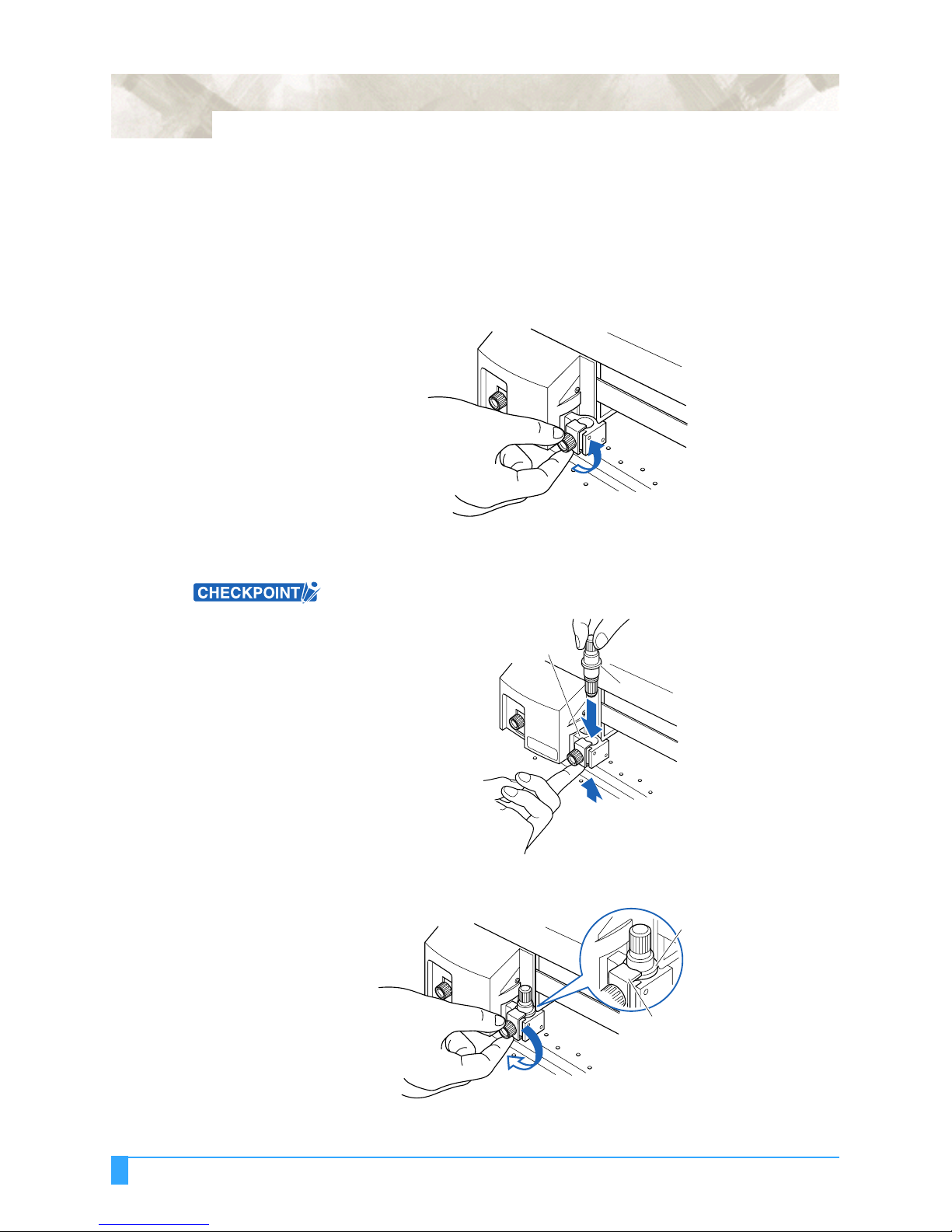
1.5 Attaching a Cutter Pen
When mounting the cutter pen in the pen holder, push the pen all the way into the
holder until its flange contacts the upper part of the holder and then tighten the
screw firmly. To prevent injury, avoid touching the pen immediately after the cutting
plotter is turned on or whenever the pen is moving.
1 Loosen the pen holder screw.
2 While pushing the pen holder in the upward direction, push the pen all the way
into the holder until its flange contacts the upper part of the holder.
When pushing the pen holder with your fingers, the blade tip may be
protruding. Take care not to cut your fingers.
Upper part of pen holder
Flange
3 Make sure that the pen bracket is engaged on the pen’s flange, and then
tighten the screw.
Flange
Bracket to hold pen
Out of the Box: Attaching a Cutter Pen
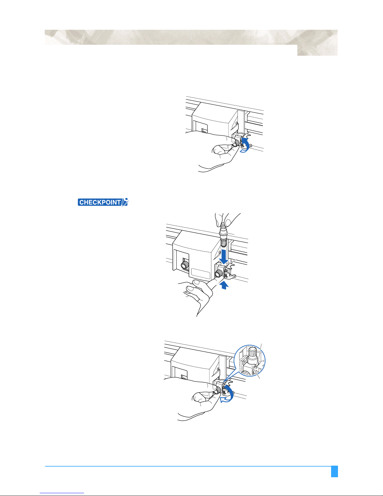
Attaching a Pen to the Two-Pen Holder (Option)
The two-pen holder is a factory-installed option, and cannot be retrofitted.
1 Loosen the pen holder screw.
2 While pushing the pen holder in the upward direction, push the pen all the way
into the holder until its flange contacts the upper part of the holder.
When you push the pen holder with your fingers, the blade tip may be
protruding. Take care not to cut your fingers.
1 - 11
Flange
Upper part of pen holder
3 Make sure that the pen bracket is engaged on the pen’s flange, and then
tighten the screw.
Flange
Bracket to hold pen
Out of the Box: Attaching a Cutter Pen
1 - 12
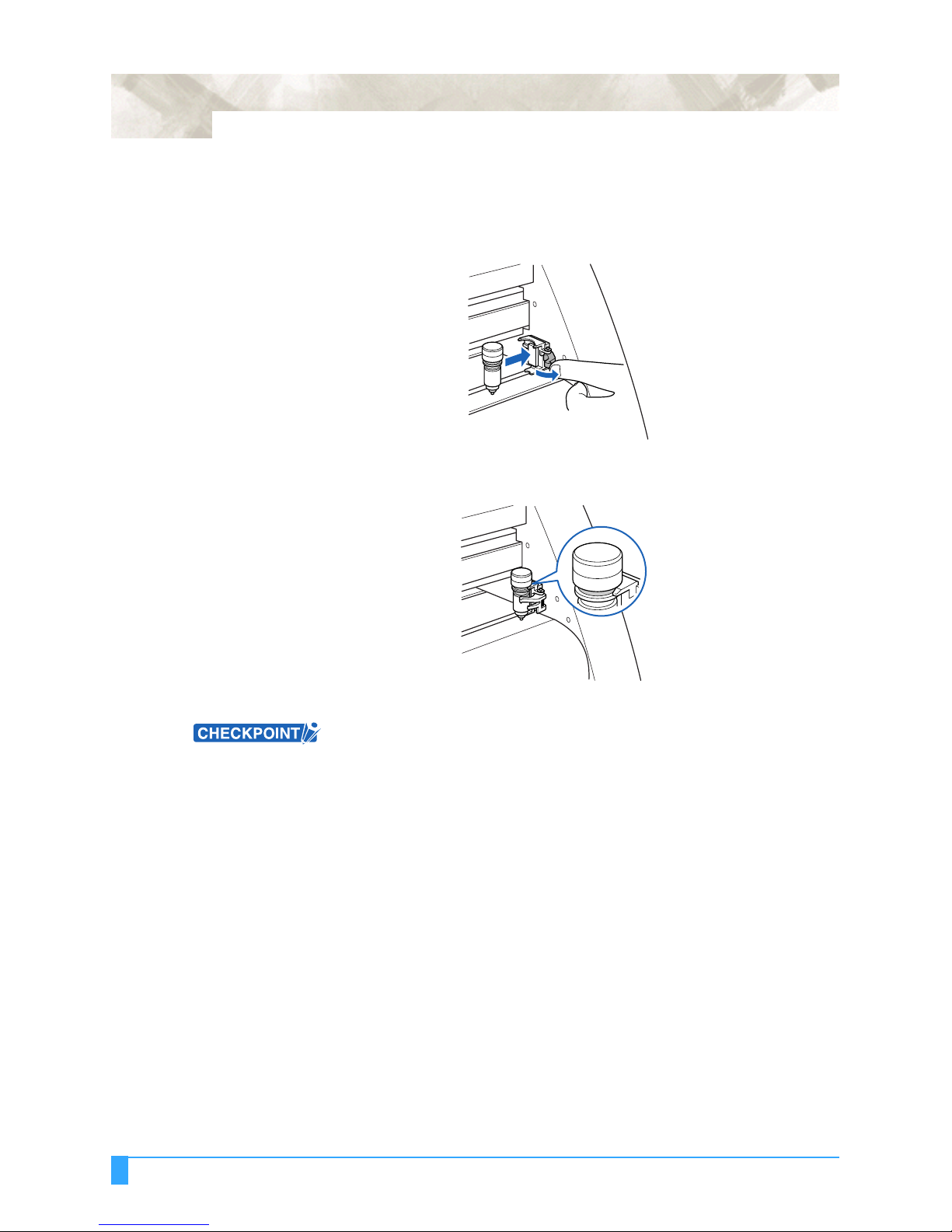
Attaching a Plotting Pen to the Pen Station
Follow the procedure below to replace the cross-cutter unit that is used to cut the
media after the plotting or cutting operation has been completed.
1 Open the pen-hold mechanism on the pen station, and then attach a pen.
2 Make sure that the bracket of the pen station is engaged in the upper groove of
the pen.
3 Close the pen-hold mechanism on the pen station to hold the pen in place.
• Do not leave a pen attached to the pen station for a long period of time, as the
pen tip will dry up and make it unusable.
• To store the pen, remove it from the pen station and replace its protective cap.
Out of the Box: Attaching a Cutter Pen
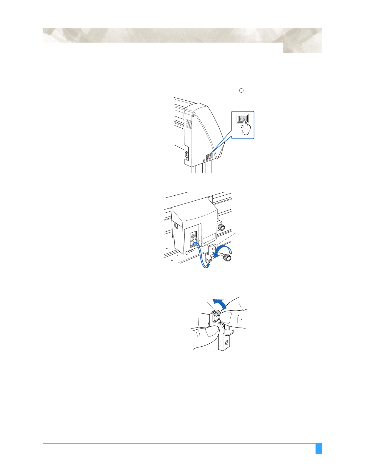
1.6 Replacing the Cross-Cutter Unit
1 Check that the power switch is turned off (the " " side is pressed down).
2 Remove the screw holding the cross-cutter unit in place, and then remove the
cross-cutter unit.
1 - 13
Cross-cutter unit
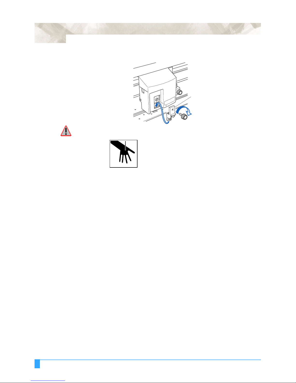
3 Remove the protective cover from the replacement cross-cutter unit. Be sure
to remove the protective cover while holding the part of the unit shown in the
figure below.
Protective cover
Out of the Box: Replacing the Cross-Cutter Unit
1 - 14
4 Attach the replacement cross-cutter unit, and tighten the screw to hold it in
place.
Cross-cutter unit
WARNING: The cross-cutter unit uses a very sharp blade. Take care not to cut your-
self on the blade.
Out of the Box: Replacing the Cross-Cutter Unit

Chapter 2: Cutter Blades
and Cutter Pens
This chapter describes the different cutter blades and cutter
pens.
Topics in this chapter
2.1 Blade Application and Features
2.2 Cutter Pen Nomenclature
2.3 Replacing the Cutter Blade
2.4 Adjusting the Blade Length
2 - 2
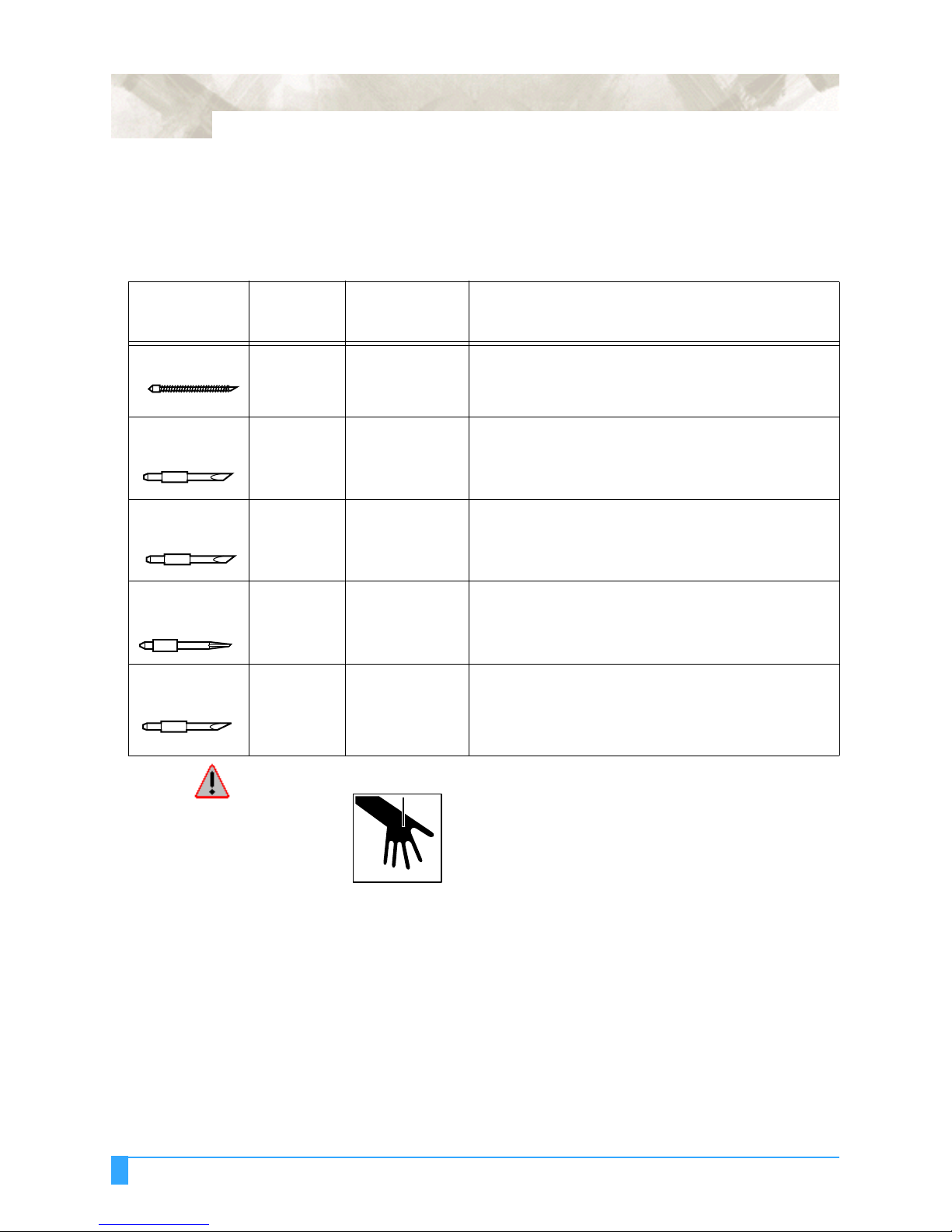
2.1 Blade Application and Features
Individual cutter blades have a variety of features. Select the optimal cutter blade
to suit the medium to be cut.
Blade part
no. and type Diameter
CB09UA 0.9 mm PHP32-CB09N Standard blade for cutting color adhesive media. Suit-
CB15U 1.5 mm PHP32-CB15N For cutting media which is too thick for the CB09UA
CB15UA 1.5 mm PHP32-CB15N For cutting high intensity reflective media.
CB15UB 1.5 mm PHP32-CB15N For cutting small characters on mono-vinyl chloride
CB15U-K30 1.5 mm PHP32-CB15N
Plunger part
no. Applications and features
able for cutting media up to 0.25 mm thick. Maximum cutting distance of approximately 4000 m.
blade to handle. Suitable for cutting media from 0.25 mm
to 0.5 mm thick.
media. Suitable for cutting small size characters that are
less than 10mm.
For cutting sandblast rubber. The sharply angled point
or
PHP32-CB15
provides a longer cutting edge. Suitable for cutting material from 0.05 mm to 1.5 mm thick.
WARNING: To avoid bodily injury, handle the cutter blade with care.
Cutter Blades and Cutter Pens: Blade Application and Features
 Loading...