

Vinten V4095-0001 User manual
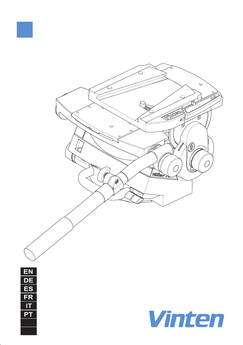
Vector 75 Pan and Tilt Head
V4095-0001
JP
CN
Operators Guide
V4095-4980/2

Vector 75
Pan and Tilt Head
Publication Part No. V4095-4980 Issue 2
English . . . . . . . . . . . . . . . . . . . . . Page 3
Deutsch . . . . . . . . . . . . . . . . . . . Seite 17
Español . . . . . . . . . . . . . . . . . .Página 33
Français . . . . . . . . . . . . . . . . . . . Page 49
Italiano . . . . . . . . . . . . . . . . . . .Pagina 65
Português . . . . . . . . . . . . . . . .Página 81
日本語 . . . . . . . . . . . ページ 97
中文 . . . . . . . . . . . . .页码 119

Copyright © 2011 The Vitec Group plc
All rights reserved throughout the world. No part of this
document may be stored in a retrieval system, transmitted,
copied or reproduced in any way, including, but not limited
to, photocopy, photograph, magnetic or other record
without the prior agreement and permission in writing of
the Vitec Group plc.
Trademarks
Vinten™, Vector
®
and Quickfix® are registered trademarks
of the Vitec Group plc.
Disclaimer
Information contained within this document is subject to
change. Camera Dynamics Limited reserves the right,
without notice, to make changes in equipment design or
performance as progress in engineering, manufacturing or
technology may warrant.
Published by
Vitec Group Videocom Division
Technical Publications Department
William Vinten Building
Western Way
Bury St Edmunds
Suffolk IP33 3TB
United Kingdom
Email: technical.publications@vitecgroup.com

English
Contents
Page
Safety – read this first . . . . . . . . . . . . . . . . . . . . . . . . . . . . . . . . . . . . . . . . . . . . . .4
Warning symbols in this Operators Guide . . . . . . . . . . . . . . . . . . . . . . . . . . . . . . . . . . . . . 4
Usage. . . . . . . . . . . . . . . . . . . . . . . . . . . . . . . . . . . . . . . . . . . . . . . . . . . . . . . . . . . . 4
Caring for the environment by recycling. . . . . . . . . . . . . . . . . . . . . . . . . . . . . . .4
Technical specification . . . . . . . . . . . . . . . . . . . . . . . . . . . . . . . . . . . . . . . . . . . . .5
Introduction and description. . . . . . . . . . . . . . . . . . . . . . . . . . . . . . . . . . . . . . . . .7
Perfect Balance . . . . . . . . . . . . . . . . . . . . . . . . . . . . . . . . . . . . . . . . . . . . . . . . . . . . . . . . . 7
Pan and tilt drag. . . . . . . . . . . . . . . . . . . . . . . . . . . . . . . . . . . . . . . . . . . . . . . . . . . . . . . . . 7
Pan and tilt brakes. . . . . . . . . . . . . . . . . . . . . . . . . . . . . . . . . . . . . . . . . . . . . . . . . . . . . . . 7
Illuminated level bubble . . . . . . . . . . . . . . . . . . . . . . . . . . . . . . . . . . . . . . . . . . . . . . . . . . . 7
Pan bar . . . . . . . . . . . . . . . . . . . . . . . . . . . . . . . . . . . . . . . . . . . . . . . . . . . . . . . . . . . . . . . 7
Camera mounting . . . . . . . . . . . . . . . . . . . . . . . . . . . . . . . . . . . . . . . . . . . . . . . . . . . . . . . 7
Operation . . . . . . . . . . . . . . . . . . . . . . . . . . . . . . . . . . . . . . . . . . . . . . . . . . . . . . . .8
Unpacking . . . . . . . . . . . . . . . . . . . . . . . . . . . . . . . . . . . . . . . . . . . . . . . . . . . . . . . . . . . . . 8
Mounting the head. . . . . . . . . . . . . . . . . . . . . . . . . . . . . . . . . . . . . . . . . . . . . . . . . . . . . . . 8
Pan bars. . . . . . . . . . . . . . . . . . . . . . . . . . . . . . . . . . . . . . . . . . . . . . . . . . . . . . . . . . . . . . . 8
Fitting a camera. . . . . . . . . . . . . . . . . . . . . . . . . . . . . . . . . . . . . . . . . . . . . . . . . . . . . . . . . 9
Balancing the head . . . . . . . . . . . . . . . . . . . . . . . . . . . . . . . . . . . . . . . . . . . . . . . . . . . . . . 9
Locking the platform. . . . . . . . . . . . . . . . . . . . . . . . . . . . . . . . . . . . . . . . . . . . . . . . . . . . . 11
Pan and tilt brakes. . . . . . . . . . . . . . . . . . . . . . . . . . . . . . . . . . . . . . . . . . . . . . . . . . . . . . 11
Pan and tilt drag. . . . . . . . . . . . . . . . . . . . . . . . . . . . . . . . . . . . . . . . . . . . . . . . . . . . . . . . 11
Maintenance . . . . . . . . . . . . . . . . . . . . . . . . . . . . . . . . . . . . . . . . . . . . . . . . . . . . .12
General . . . . . . . . . . . . . . . . . . . . . . . . . . . . . . . . . . . . . . . . . . . . . . . . . . . . . . . . . . . . . . 12
Cleaning. . . . . . . . . . . . . . . . . . . . . . . . . . . . . . . . . . . . . . . . . . . . . . . . . . . . . . . . . . . . . . 12
Cleaning balance mechanism tracks. . . . . . . . . . . . . . . . . . . . . . . . . . . . . . . . . . . . . 12
Routine maintenance. . . . . . . . . . . . . . . . . . . . . . . . . . . . . . . . . . . . . . . . . . . . . . . . . . . . 13
Replacing the battery. . . . . . . . . . . . . . . . . . . . . . . . . . . . . . . . . . . . . . . . . . . . . . . . . 13
Adjustments. . . . . . . . . . . . . . . . . . . . . . . . . . . . . . . . . . . . . . . . . . . . . . . . . . . . . . . . . . . 14
Adjusting the slide plate clamp . . . . . . . . . . . . . . . . . . . . . . . . . . . . . . . . . . . . . . . . . 14
Repositioning the wedge adaptor . . . . . . . . . . . . . . . . . . . . . . . . . . . . . . . . . . . . . . . 14
Adjusting the pan and tilt brakes . . . . . . . . . . . . . . . . . . . . . . . . . . . . . . . . . . . . . . . . 15
Parts list . . . . . . . . . . . . . . . . . . . . . . . . . . . . . . . . . . . . . . . . . . . . . . . . . . . . . . . . 16
3
English
CAUTION
finger trap
Safety – read this first
Warning symbols in this Operators Guide
WARNING
Where there is a risk of personal injury or injury to others, comments appear
highlighted by the word ‘WARNING’—supported by the warning triangle symbol.
Where there is a risk of damage to the product, associated equipment, process or
surroundings, comments appear highlighted by the word ‘CAUTION’.
FINGER TRAP
Where there is a risk of trapping fingers within parts of the product or other
equipment mounted to the product, comments appear supported by the finger trap
symbol.
Usage
The Vector 75 pan and tilt head is designed for use in broadcast and film studios to support and
balance a camera and ancillary equipment weighing up to 75 kg (165.3 lb), and must be mounted
on equipment designed to support a minimum payload of 95 kg (209 lb).
The Vector 75 pan and tilt head is intended for use by professional TV broadcast and film
camera operators.
WARNING!
1. Do NOT attempt to use this product if you do not fully understand how
to operate it.
2. Do NOT use this product for any other purpose than that specified in
the Usage statement.
3. Refer all maintenance beyond that detailed in this Operators Guide to
an authorised Vinten service centre.
Caring for the environment by recycling
Disposal of waste batteries
Any batteries included with this product must not be treated as household waste. By ensuring
these batteries are disposed of correctly, you will help pre vent potentially negative consequences
for the environment and human health, and help conserve natural resources. Hand the battery
over to the applicable collection point for recycling waste batteries.
4

English
Technical specification
Maximum payload . . . . . . . . . . . . . . . . . . . . . . . . . . . . . . . . . . . . . . . . . . . . . . . 75 kg (165.3 lb)
Payload Centre of Gravity height range. . . . . . . . . . . . . . . . . . . . . . . . . . 80–250 mm (3–10 in.)
Weight (complete with pan bar and wedge adaptor) . . . . . . . . . . . . . . . . . . . .19.15 kg (42.2 lb)
Overall dimensions:
Height (with wedge adaptor)
Minimum balance setting . . . . . . . . . . . . . . . . . . . . . . . . . . . . . . . . .255 mm (10.0 in.)
Maximum balance setting. . . . . . . . . . . . . . . . . . . . . . . . . . . . . . . . .355 mm (14.0 in.)
Length (without pan bar) . . . . . . . . . . . . . . . . . . . . . . . . . . . . . . . . . . . .355 mm (14.0 in.)
Width (without pan bar) . . . . . . . . . . . . . . . . . . . . . . . . . . . . . . . . . . . . .350 mm (13.8 in.)
Width (with two pan bars). . . . . . . . . . . . . . . . . . . . . . . . . . . . . . . . . . . .445 mm (17.5 in.)
Tilt range. . . . . . . . . . . . . . . . . . . . . . . . . . . . . . . . . . . . . . . . . . . . . . . . . . . . . . . . . . . . . . . . . . . . . . . ±52
Pan range. . . . . . . . . . . . . . . . . . . . . . . . . . . . . . . . . . . . . . . . . . . . . . . . . . . . . . . . . . . . . . . 360
Counterbalance . . . . . . . . . . . . . . . . . . . . . . . . . . . . . . . . fully variable Perfect Balance system
Level bubble. . . . . . . . . . . . . . . . . . . . . . . . . . . . . . . . . . . . . illuminated, high contrast blue LED
Level bubble illumination . . . . . . . . . . . . . . . . . . . . . . . . . . . . . . . . . . . . . . 15 seconds (timeout)
Battery . . . . . . . . . . . . . . . . . . . . . . . . . . . . . . . . . . . . . . . . . . . . . . . . . . . . . . . . . . . . . .PP3 (9V)
Tripod fixing . . . . . . . . . . . . . . . . . . . . . . . . Four-bolt flat base with Quickfix
®
groove (standard)
5

English
Vector 75
Pan and Tilt Head, left side
(Fig. 1)
[1] . . . . . . . . . . . . . . . . . . . . . . . . . . . . . . . . . . . . . . . . . . . . . . . . . . . . . . . . . . . . .Wedge adaptor
[2] . . . . . . . . . . . . . . . . . . . . . . . . . . . . . . . . . . . . . . . . . . . . . . . . . . . . . . . . Wedge adaptor lever
[3] . . . . . . . . . . . . . . . . . . . . . . . . . . . . . . . . . . . . . . . . . . . . . . . . Wedge adaptor securing screw
[4] . . . . . . . . . . . . . . . . . . . . . . . . . . . . . . . . . . . . . . . . . . . . . . . . . . . . . . . . . . . . Pan brake lever
[5] . . . . . . . . . . . . . . . . . . . . . . . . . . . . . . . . . . . . . . . . . . . . . . . . . . . . . . . . . . . . . Tilt brake lever
[6] . . . . . . . . . . . . . . . . . . . . . . . . . . . . . . . . . . . . . . . . . . . . . . . . . . . . . . . . . . . . Carrying handle
[7] . . . . . . . . . . . . . . . . . . . . . . . . . . . . . . . . . . . . . . . . . . . . . . . .Level bubble illumination switch
[8] . . . . . . . . . . . . . . . . . . . . . . . . . . . . . . . . . . . . . . . . . . . . . . . . . . . . . . . . . . . . . . .Level bubble
[9] . . . . . . . . . . . . . . . . . . . . . . . . . . . . . . . . . . . . . . . . . . . . . . . . . . . . Pan drag adjustment knob
[10] . . . . . . . . . . . . . . . . . . . . . . . . . . . . . . . . . . . . . . . . . . . . . . . . . . . . . . . . . . . . Pan bar clamp
[11] . . . . . . . . . . . . . . . . . . . . . . . . . . . . . . . . . . . . . . . . . . . . . . . . . . . .Tilt drag adjustment knob
[12] . . . . . . . . . . . . . . . . . . . . . . . . . . . . . . . . . . . . . . . . . . . . . . . . . . . . . . . . . . Slide plate clamp
[13] . . . . . . . . . . . . . . . . . . . . . . . . . . . . . . . . . . Slide plate adjustment knob (retractable ‘T’ bar)
Vector 75
Pan and Tilt Head, right side
(Fig. 2)
[14] . . . . . . . . . . . . . . . . . . . . . . . . . . . . . . . . . . . . . . . . . . . . . . . . . . . . . . . . . . . . . . . Slide plate
[15] . . . . . . . . . . . . . . . . . . . . . . . . . . . . . . . . . . . . . . . . . . . . . Perfect Balance adjustment knob
[16] . . . . . . . . . . . . . . . . . . . . . . . . . . . . . . . . . . . . . . . . . . . . . . . . . . . . . . . . . Centre lock button
[17] . . . . . . . . . . . . . . . . . . . . . . . . . . . . . . . . . . . . . . . . . . . . . . . . . . . .Centre lock release catch
[18] . . . . . . . . . . . . . . . . . . . . . . . . . . . . . . . . . . . . . . . . . . . . . . . . . . . . . . . . . . . . Pan bar mount
Vector 75
Pan and Tilt Head, underside
(Fig. 3)
[19] . . . . . . . . . . . . . . . . . . . . . . . . . . . . . . . . . . . . . . . . . . . . . . . . . . . . . . . . . . . . Bolt fixing hole
[20] . . . . . . . . . . . . . . . . . . . . . . . . . . . . . . . . . . . . . . . . . . . . . . . . . . .Bolt-hole position indicator
6

English
Introduction and description
The Vector 75 pan and tilt head embod i es a u niqu e lin kag e co un terb alan cing me cha nism,
patented Vinten lubricated friction (LF) drag assemblies for pan and tilt motions and an
adjustable camera mounting plate.
Perfect Balance
The balance system is easily adjusted by a knob [15] on the right side of the head. The Perfect
Balance adjustment control compensates for differing platform load/C of G heights by varying
the mechanical advantage of a bell-crank in the counterbalance mechanism.
Pan and tilt drag
Both the pan and tilt mechanisms incorporate lubricated friction (LF) drag systems to ensure
smooth movement of the camera about these axes and are fitted with control knobs ([9], [11]) to
adjust the drag setting. The drag controls are mounted on the left side of the head. The whippan facility is unaffected by the pan drag setting.
Pan and tilt brakes
Friction brakes on each axis allow the head to be locked at any chosen position. The operating
levers for both brakes ([4], [5]) are fitted on the lower right rear of the head. A tilt axis centre lock
[16] is provided on the right side of the head to secure the platform in the horizontal position
during transport or load changing.
Illuminated level bubble
A level bubble [8] is fitted to the rear of the head and is provided with a time-delay illumination
unit, operated by a switch [7]. The battery for the illumination unit is contained in the base.
Pan bar
Pan bar mounting points [18] are located at the rear of the head, on either side of the camera
mounting platform. A telescopic pan bar is supplied and is attached using a pan bar clamp [10],
with angular adjustment available on the mount serrations. A second pan bar may be fitted;
telescopic and fixed short or extra short pan bars are available as optional extras.
Camera mounting
The camera is attached to the head by means of a wedge adaptor [1].
7

English
Operation
Unpacking
The head is supplied with a telescopic pan bar, automatic wedge adaptor and a battery (already
fitted) for the level bubble illumination unit.
A second telescopic or fixed short or extra short pan bar for use with a zoom or focus controller
is optional. Ensure that all items are unpacked prior to disposal of the packing materials.
After unpacking ensure that:
The pan and tilt brakes ([4], [5]) are on (see Pan and tilt brakes on page 11).
The centre lock [16] is engaged (see Locking the platform on page 11). Always
engage the centre lock before lifting or carrying the head.
CAUTION! Do NOT lift the head by the platform. Only use the base and/or the
carrying handle to prevent damaging the head.
Mounting the head
NOTE: When mounted on Vinten ‘Hawk’ or ‘Teal’ pedestals, clearance between the
The head is mounted on a tripod, pedestal or suitable firm surface using the four fixing bolts and
washers. The four bolt-fixing holes [19] on the underside of the head are easily located using the
bolt-hole position indicators [20]. Tighten the bolts with the spanner provided.
After mounting the head, ensure it is level using the level bubble [8], which may be illuminated
by pressing the switch [7]. The light will go out after 15 seconds (timeout function).
head and the pedestal weight tray prevents the use of 1.6 kg (5.5 lb) and
0.5 kg (1.0 lb) trim weights. Use alternative weights or fit the adaptor plate
kit (part no. 3354-900SP) between the head and pedestal.
WARNING!
1. Only mount this product on equipment designed to support a
minimum of 95 kg (109 lb).
2. Before installing the head, hold a fixing bolt in position and check that
the threaded end does not project more than 20 mm (3/4 in.) above the
mounting face.
Pan bars
Fit the pan bars to the head and adjust the position of each one before tightening the clamp [10]
on the mounting [18]. Adjust the length of the telescopic pan bar(s).
8

Fitting a camera
WARNING!
1. Do NOT rely on the tilt brake when changing the payload. Always
engage the centre lock.
2. Ensure that the weight and C of G height of the total payload is within
the range for which the head is designed: up to 75 kg (165.3 lb) with a
C of G height of 80–250 mm (3–10 in).
To fit a camera, proceed as follows:
Lower the mounting to a convenient working height.
If not already fitted, install the wedge adaptor [1] in the middle position on the slide plate
[14] (see Repositioning the wedge adaptor on page 14).
Attach the wedge to the camera/lens.
Ensure that the centre lock [16] is engaged (see Locking the platform on page 11).
Apply the pan brake [4] (see Pan and tilt brakes on page 11)
Slide the wedge adaptor lever [2] forward (parallel to the wedge) about 6 mm (1/4 in.)
against spring tension. Pull the lever out, away from the body of the wedge adaptor, as
far as it will go.
Insert the camera wedge into the wedge adaptor [1] and push it forward until it is fully
engaged. Push in the wedge adaptor lever [2], until it lies parallel with the wedge adaptor
body. During this operation the resistance of the spring-loaded over-centre mechanism
will be felt. As the lever reaches the end of its travel, it will snap into the locked position
(indicated by the closed padlock symbol above the lever).
Confirm that the lever is locked by briefly pulling it outward, away from the wedge
adaptor body. If the lever is locked, it should not move and the closed padlock
symbol only should be visible.
Install the remainder of the payload (e.g. lens, zoom and focus controls, viewfinder,
prompter etc.).
.
English
Balancing the head
NOTE: It is important that the pan bar(s) and all camera accessories (lens, zoom
and focus controls, viewfinder, prompter etc.) are fitted in their operational
position before balancing the head.
Any equipment fitted or adjusted later will unbalance the head.
Balancing the head consists of positioning the payload fore and aft on the head so that its C of G
is immediately above the platform pivot, then compensating for the payload C of G height using
the Perfect Balance adjustment knob.
9

English
Position the payload fore and aft as follows:
Ensure that the centre lock is engaged (see Locking the platform on page 11) and that
the camera and all accessories are fitted.
Turn the tilt drag adjustment knob [11] to its minimum setting.
WARNING!
Increase the balance setting for a heavy, out-of-balance payload BEFORE
disengaging the centre lock, to prevent the platform tipping violently.
Holding the pan bar to steady the platform, press down the release catch [17] to
disengage the centre lock (see Locking the platform on page 11).
Push the clamp lever [12] downward to release the slide plate clamp and pull out the
slide plate adjustment knob or ‘T’ bar [13] until it engages with the platform drive. Turn
the ‘T’ bar to move the slide plate fore and aft to achieve horizontal balance.
The horizontal balance is correct when no perceptible tilting force can be felt on the pan
bar with the platform level. Apply the slide plate clamp [12] by pulling the clamp lever
upward.
If there is insufficient movement in the slide plate to achieve balance, reposition the wedge
adaptor (see Maintenance on page 12), refit the load and repeat the horizontal balancing
procedure.
When fore and aft balance has been achieved, adjust the payload C of G height as follows:
WARNING!
Keep a firm grip on the pan bar to steady the camera payload.
Be prepared to prevent the head falling away suddenly.
Using the pan bar, tilt the platform forward and backward. When correctly balanced,
there should be no perceptible tilting force on the pan bar at any angle of tilt and the head
should remain in any tilt position to which it is set.
If the head tends to fall away when the platform is tilted, push and turn the Perfect
Balance adjustment knob [15] clockwise to increase the C of G height setting. If the head
tends to spring back to centre, push and turn the Perfect Balance adjustment knob [15]
counter-clockwise to decrease the C of G height setting.
NOTE: The Perfect Balance adjustment knob is a multi-turn control. To enable the
knob to be turned more easily, slightly tilt the platform using the pan bar
whilst turning the knob.
When the payload C of G height adjustment is complete, check that the fore and aft
balance remains satisfactory. Readjust the position of the slide plate if necessary.
After balancing, release the brakes and exercise the head through both axes to confirm that it
operates smoothly.
10

English
CAUTION
finger trap
Locking the platform
(Fig 4)
The centre lock mechanism is operated by a button [16] on the right side of the head. To engage
the lock, hold the platform in the horizontal position and push the button [16] inwards, until it
latches and the release catch [17] appears. Use the pan bar to rock the platform slightly whilst
pushing the button [16].
To release the centre lock, rock the platform slightly and push down on the release catch [17].
WARNING! FINGER TRAP
Keep fingers clear of the platform underside when tilting to avoid
personal injury.
Pan and tilt brakes
The pan and tilt brakes are operated by levers ([4], [5]) at the rear of the head. They are applied
by pulling the appropriate lever up and back and released by pushing the lever forwards.
CAUTION!
1. Do NOT use force on the brake levers. Hand tighten only.
2. Do NOT use the brakes to supplement drag, the head may b e damaged.
When the brakes are not in use, always ensure they are fully released.
The brakes should be applied whenever the camera is left unattended.
Pan and tilt drag
The pan drag adjustment knob [9] is mounted on the left lower part of the main body. Tilt drag is
adjusted by a knob [11] mounted on the face of the tilt drag housing on the left side of the head.
Turn the knobs clockwise to increase drag and counter-clockwise to decrease drag.
CAUTION! Reduce drag to a minimum when the head is out of use for long periods,
to minimise wear on drag components.
11

English
Maintenance
General
The Vector 75 pan and tilt head is robustly made to high engineering standards and little
attention is required to maintain serviceability except regular cleaning. Adjustments and repairs
should be carried out only by a competent person.
Cleaning
During normal use the only cleaning required should be a regular wipe over with a lint-free cloth.
Dirt accumulated during storage or periods of disuse may be removed with a vacuum cleaner.
Particular attention should be paid to the wedge location faces of the wedge adaptor.
CAUTION! DO NOT use solvent- or oil-based cleaners, abrasives or wire brushes to
remove accumulations of dirt as these damage the protective surfaces.
To clean mechanical surfaces, use only detergent-based cleaners.
Use out-of-doors under adverse conditions may require special attention, and the head should
be covered when not in use. Salt spray should be washed off using fresh water at the earliest
opportunity. Sand and dirt act as an abrasive and should be removed using a vacuum cleaner
or a supply of clean, dry air.
Cleaning balance mechanism tracks
The balance mechanism tracks are automatically cleaned by built-in wipers, but after use in
particularly adverse conditions the tracks may require cleaning. Some dismantling of the head
is necessary and it is recommended that this be carried out in clean workshop conditions.
Vertical tracks (Fig 5)
To clean the vertical tracks it is necessary to remove the platform; proceed as follows:
Remove the payload (if fitted). It is not necessary to remove the wedge adaptor.
Release the slide plate clamp [12]. Use the adjustment knob [13] to wind the slide plate
[14] backwards until it is clear of fixing screws [21].
Level the platform.
Remove six screws [21] securing the platform [22] to the balance mechanism [23]. Lift
off the platform.
Using a pipe cleaner (or similar) moistened with an isopropanol-based cleaner (3M
VBH or similar) clean the two vertical tracks [24]. Upwards pressure on the balance
mechanism will allow the area of track under the vertical rollers to be cleaned.
Install the platform [22] on the balance mechanism [23] and secure with six screws [21]
using Loctite 222E.
Using the adjustment knob [13] wind the slide plate forwards to the central position.
Refit the payload (if required) and rebalance the head.
12

Horizontal tracks (Fig 6)
No dismantling is necessary to clean the horizontal tracks; proceed as follows:
Remove the payload (if fitted).
Set the balance mechanism to its maximum setting by pushing in the Perfect Balance
knob [15] and turning it clockwise to its stop.
Tilt the platform fully backwards and apply the tilt brake [5].
Pull down the flap guard [28] to reveal the bevel gear [26]. Access to the horizontal
tracks [27] is through the holes in the bevel gear, which may be rotated freely.
Using a pipe cleaner (or similar) moistened with an isopropanol-based cleaner (3M VBH
or sim.), clean the two horizontal tracks. Upwards pressure on the balance mechanism
will allow the area of track under the horizontal rollers to be cleaned.
Release the flap guard [28] and the tilt brake [5] and return the platform to the horizontal
position.
Refit the payload (if required).
Routine maintenance
Routine maintenance on the Vector 75 pan and tilt head is limited to annual replacement
of the level bubble illumination battery.
During normal use, check the effectiveness of the platform slide clamp and the
adequacy of level bubble illumination.
No further routine maintenance is required.
English
Replacing the battery
(Fig 7)
The level bubble on the Vector 75 pan and tilt head is illuminated by a battery-powered LED. A
time-delay circuit initiated by a switch controls the LED. The battery should be replaced at yearly
intervals or whenever the illumination is considered inadequate.
NOTE: Dependent on the type of mounting, it may be necessary to remove the
head from the mounting for access to the battery compartment.
To install or replace the battery proceed as follows:
Remove three screws [29] which secure the battery compartment cover plate [32].
Install the battery [30] by pushing the connector [31] onto the battery terminals.
Position the battery in the battery compartment, ensuring that the wiring is not trapped.
Refit the battery compartment cover plate [32], ensuring battery locates in cover plate.
Secure with three screws [29].
Press the switch [7] and ensure the LED is lit for approximately 15 seconds.
13

English
Adjustments
After considerable use the slide plate clamp may require adjustment.
To enable the payload to be correctly balanced, the wedge adaptor may require
repositioning.
The pan and tilt brakes may require adjustment after considerable use.
Adjusting the slide plate clamp
(Fig 8)
The slide plate clamp [12] should be set so that in the up or clamped position it prevents the slide
plate from being moved, while in the down or released position it allows free adjustment of the
slide plate. To adjust the clamp, proceed as follows:
On the left-hand side of the platform, carefully remove the plastic cap [12.2] to reveal the
slotted shaft [12.1].
Pull the slide plate clamp lever [12] fully upwards.
Slacken the clamp screw [12.3].
Turn the slotted shaft [12.1] fully clockwise to apply the clamp.
Tighten the clamp screw [12.3].
Move the lever over its full range and ensure that in the clamped position it prevents the
slide from being moved, while in the released position it allows free adjustment of the
slide. Readjust if necessary.
Replace the plastic cap [12.2] over the slotted shaft [12.1].
Repositioning the wedge adaptor
(Fig 9)
The wedge adaptor [1] is secured by four cap head screws [3] which pass through the wedge
adaptor into the slide plate [14].
WARNING!
Overlong screws will prevent the slide plate from operating. Always use the
screws provided (M6 x 30 mm).
To reposition the wedge adaptor:
Engage the centre lock (see Locking the platform on page 11) and remove the load.
Hold the body of the wedge adaptor [1] and use a 4 mm hexagon wrench to remove four
securing screws [3].
Reposition the wedge adaptor [1] on the slide plate [14], ensuring that the narrow end
of the wedge adaptor faces forwards.
Insert the four screws [3] in the holes in the wedge adaptor and tighten.
14

English
Adjusting the pan and tilt brakes
(Fig 10)
The pan and tilt brakes should be set so that the brakes begin to be applied after approximately
one-third of the lever travel. The tilt brake is adjusted by inserting a 2 mm hexagon wrench
through the hole [5.2] in the bottom of the tilt unit cover and turning the grub screw [5.1].
To adjust the tilt brake, proceed as follows:
Operate the tilt brake lever [5] from the OFF to the ON position.
If brake pressure is not felt after approximately 1/3 of lever travel, turn the grub screw [5.1]
clockwise until this is achieved.
Operate the tilt brake lever [5] to the OFF position and ensure that the platform is free
to move.
The pan brake is adjusted by turning the pin [4.3]. To gain access to the pin it is necessary to
remove the payload from the head, remove the head from its mounting and remove a cover plate
[4.1] from the underside of the head.
To adjust the pan brake, proceed as follows:
WARNING!
Remove the payload before adjusting the pan brake.
Remove the payload from the head.
Remove the head from its mounting.
On the underside of the head, remove three screws [4.2] securing the cover plate [4.1].
Operate the pan brake lever [4] from the OFF to the ON position.
If brake pressure is not felt after approximately 1/3 of the lever travel, turn the pin [4.3]
clockwise until this is achieved.
Set the pan brake lever [4] to the OFF position and ensure that the head is free to rotate.
Refit the cover plate [4.1] and secure with three screws [4.2].
15

English
Parts list
The following list includes main assemblies, user-replaceable spare parts and optional
accessories. For further information regarding repair or spare parts, please contact Vinten or
your local Vinten distributor. For more information visit our website at www.vinten.com.
Main assemblies
Vector 75 pan and tilt head. . . . . . . . . . . . . . . . . . . . . . . . . . . . . . . . . . . . . . . . . . . . V4095-0001
Telescopic pan bar and clamp assembly . . . . . . . . . . . . . . . . . . . . . . . . . . . . . . . . . . . . 3219-82
Automatic wedge adaptor. . . . . . . . . . . . . . . . . . . . . . . . . . . . . . . . . . . . . . . . . . . . . . . . . 3460-3
Fixing bolts (4 off). . . . . . . . . . . . . . . . . . . . . . . . . . . . . . . . . . . . . . . . . . . . . . . . . . . . . L054-714
Washers (4 off, for fixing bolts). . . . . . . . . . . . . . . . . . . . . . . . . . . . . . . . . . . . . . . . . . . L602-122
Spanner (for head bolts). . . . . . . . . . . . . . . . . . . . . . . . . . . . . . . . . . . . . . . . . . . . . . . . J551-001
Battery (9V, PP3) . . . . . . . . . . . . . . . . . . . . . . . . . . . . . . . . . . . . . . . . . . . . . . . . . . . . . C550-023
User-replaceable spare parts
Level bubble illumination unit battery – 9V, 6LR61
(PP3, 6AM6, MN1604, E-BLOCK or equivalent) . . . . . . . . . . . . . . . . . . . . . . . . . . . . . C550-023
Vinten Flat-Base Head-Fixing Kit (SP). . . . . . . . . . . . . . . . . . . . . . . . . . . . . . . . . . . V4095-1902
Optional accessories
Lightweight Mitchell adaptor. . . . . . . . . . . . . . . . . . . . . . . . . . . . . . . . . . . . . . . . . . . . . . . 3103-3
Heavy-duty Mitchell adaptor for Vinten pedestal
mounting in conjunction with Hi-hat Adaptor, part no. 3055-3 . . . . . . . . . . . . . . . . . . . . . 3724-3
Adaptor Plate Kit (for use on ‘Hawk’ and ‘Teal’ pedestals). . . . . . . . . . . . . . . . . . . . 3354-900SP
Camera wedges for wedge adaptor:
Short wedge. . . . . . . . . . . . . . . . . . . . . . . . . . . . . . . . . . . . . . . . . . . . . . . . . . . . . . 3391-3
Standard wedge. . . . . . . . . . . . . . . . . . . . . . . . . . . . . . . . . . . . . . . . . . . . . . . . . . . 3053-3
Short fixed pan bar and clamp assembly. . . . . . . . . . . . . . . . . . . . . . . . . . . . . . . . . . . . 3219-94
Extra short fixed pan bar and clamp assembly . . . . . . . . . . . . . . . . . . . . . . . . . . . . . . . 3219-93
Telescopic pan bar and clamp assembly . . . . . . . . . . . . . . . . . . . . . . . . . . . . . . . . . . . . 3219-82
16

Deutsch
Inhalt
Seite
Sicherheitshinweise – Unbedingt zuerst lesen! . . . . . . . . . . . . . . . . . . . . . . . . 18
Warnsymbole in dieser Bedienungsanleitung . . . . . . . . . . . . . . . . . . . . . . . . . . . . . . . . . .18
Nutzung. . . . . . . . . . . . . . . . . . . . . . . . . . . . . . . . . . . . . . . . . . . . . . . . . . . . . . . . . 18
Umweltverträglichkeit durch Recycling. . . . . . . . . . . . . . . . . . . . . . . . . . . . . . . 18
Technische Daten. . . . . . . . . . . . . . . . . . . . . . . . . . . . . . . . . . . . . . . . . . . . . . . . . 19
Einführung und Beschreibung . . . . . . . . . . . . . . . . . . . . . . . . . . . . . . . . . . . . . . 21
Perfect Balance . . . . . . . . . . . . . . . . . . . . . . . . . . . . . . . . . . . . . . . . . . . . . . . . . . . . . . . . .21
Schwenk- und Neigungsdämpfung . . . . . . . . . . . . . . . . . . . . . . . . . . . . . . . . . . . . . . . . . . 21
Schwenk- und Neigungssperren . . . . . . . . . . . . . . . . . . . . . . . . . . . . . . . . . . . . . . . . . . . .21
Beleuchtete Nivellierlibelle. . . . . . . . . . . . . . . . . . . . . . . . . . . . . . . . . . . . . . . . . . . . . . . . . 21
Schwenkarm . . . . . . . . . . . . . . . . . . . . . . . . . . . . . . . . . . . . . . . . . . . . . . . . . . . . . . . . . . .21
Kameramontage . . . . . . . . . . . . . . . . . . . . . . . . . . . . . . . . . . . . . . . . . . . . . . . . . . . . . . . . 21
Bedienung. . . . . . . . . . . . . . . . . . . . . . . . . . . . . . . . . . . . . . . . . . . . . . . . . . . . . . . 22
Auspacken. . . . . . . . . . . . . . . . . . . . . . . . . . . . . . . . . . . . . . . . . . . . . . . . . . . . . . . . . . . . .22
Befestigen des Kopfes. . . . . . . . . . . . . . . . . . . . . . . . . . . . . . . . . . . . . . . . . . . . . . . . . . . . 22
Schwenkarme . . . . . . . . . . . . . . . . . . . . . . . . . . . . . . . . . . . . . . . . . . . . . . . . . . . . . . . . . .23
Anbringen der Kamera. . . . . . . . . . . . . . . . . . . . . . . . . . . . . . . . . . . . . . . . . . . . . . . . . . . .23
Ausbalancieren des Kopfes. . . . . . . . . . . . . . . . . . . . . . . . . . . . . . . . . . . . . . . . . . . . . . . .24
Verriegeln der Plattform. . . . . . . . . . . . . . . . . . . . . . . . . . . . . . . . . . . . . . . . . . . . . . . . . . . 25
Feststellbremsen für beide Achsen . . . . . . . . . . . . . . . . . . . . . . . . . . . . . . . . . . . . . . . . . . 26
Schwenk- und Neigedämpfung . . . . . . . . . . . . . . . . . . . . . . . . . . . . . . . . . . . . . . . . . . . . .26
Wartung. . . . . . . . . . . . . . . . . . . . . . . . . . . . . . . . . . . . . . . . . . . . . . . . . . . . . . . . . 27
Allgemeines . . . . . . . . . . . . . . . . . . . . . . . . . . . . . . . . . . . . . . . . . . . . . . . . . . . . . . . . . . . .27
Reinigung. . . . . . . . . . . . . . . . . . . . . . . . . . . . . . . . . . . . . . . . . . . . . . . . . . . . . . . . . . . . . .27
Reinigung der Spuren des Balancierungsmechanismus. . . . . . . . . . . . . . . . . . . . . . .27
Routinemäßige Wartung . . . . . . . . . . . . . . . . . . . . . . . . . . . . . . . . . . . . . . . . . . . . . . . . . . 28
Batterie wechseln . . . . . . . . . . . . . . . . . . . . . . . . . . . . . . . . . . . . . . . . . . . . . . . . . . . .28
Einstellungen . . . . . . . . . . . . . . . . . . . . . . . . . . . . . . . . . . . . . . . . . . . . . . . . . . . . . . . . . . .29
Plattformgleitklemme einstellen. . . . . . . . . . . . . . . . . . . . . . . . . . . . . . . . . . . . . . . . . .29
Neuausrichtung des Keilplattenadapters. . . . . . . . . . . . . . . . . . . . . . . . . . . . . . . . . . .30
Feststellbremsen für beide Achsen einstellen. . . . . . . . . . . . . . . . . . . . . . . . . . . . . . . 30
Teilelisten . . . . . . . . . . . . . . . . . . . . . . . . . . . . . . . . . . . . . . . . . . . . . . . . . . . . . . . 32
17
Deutsch
CAUTION
finger trap
Sicherheitshinweise – Unbedingt zuerst lesen!
Warnsymbole in dieser Bedienungsanleitung
WARNUNG
Dort, wo die Gefahr einer Verletzung für Sie oder andere besteht, sind Kommentare durch das Wort WARNUNG! besonders hervorgehoben – unterstützt
durch das dreieckige Warnsymbol.
Dort, wo die Gefahr von Schäden am Produkt, an zugehöriger Ausrüstung, dem
Prozess oder der Umgebung besteht, sind Kommentare durch das Wort VORSICHT! gekennzeichnet.
QUETSCHGEFAHR
Wenn die Gefahr besteht, sich die Finger am Produkt oder an anderen am Produkt
angebrachten Komponenten zu quetschen oder einzuklemmen, werden entsprechende Hinweise in Verbindung mit dem Symbol „Finger Trap“ angezeigt.
Nutzung
Der Vector 75 Schwenk-/Neigekopf wurde zur Verwendung im Broadcast-Bereich und in Filmstudios als Support und Balancierungsvorrichtung für Kamera und Zusatzausrüstung mit einem
Gewicht von bis zu 75 kg entwickelt, und ist auf Geräten mit einer Mindesttraglast von 95 kg
zu befestigen.
Der Vector 75 Schwenk-/Neigekopf wurde für den professionellen Einsatz durch TV-Broadcastund Filmkameraleute konzipiert.
WARNUNG!
1. Verwenden Sie dieses Produkt NICHT, wenn Sie nicht sicher si nd, wie
es zu bedienen ist.
2. Verwenden Sie dieses Produkt NICHT zu ei nem anderen Zweck a ls der
unter „Nutzung“ beschriebenen Verwendung.
3. Wenden Sie sich bezüglich aller Wartungsarbeiten, die über die in
dieser Bedienungsanleitung beschriebenen Maßnahmen hinausgehen, an ein autorisiertes Vinten Service Centre.
Umweltverträglichkeit durch Recycling
Entsorgung von Altbatterien
Die mit diesem Produkt gelieferten Batterien dürfen nicht in den Hausmüll gegeben werden.
Sorgen Sie dafür, dass diese Batterien angemessen entsorgt werden. Sie helfen damit, die
Umwelt und unsere natürlichen Ressourcen zu schonen und Gesundheitsschäden zu vermeiden. Geben Sie die Batterie an einem Sammelpunkt zum Recycling von Altbatterien ab.
18

Deutsch
Technische Daten
Maximale Traglast . . . . . . . . . . . . . . . . . . . . . . . . . . . . . . . . . . . . . . . . . . . . . . . . . . . . . . . 75 kg
Traglast Schwerpunkthöhenbereich. . . . . . . . . . . . . . . . . . . . . . . . . . . . . . . . . . . . . 80–250 mm
Gewicht (komplett mit Schwenkarm und Keilplattenadapter). . . . . . . . . . . . . . . . . . . . . 19,15 kg
Gesamtmaße
Höhe (mit Keilplattenadapter):
Minimale Balance-Einstellung . . . . . . . . . . . . . . . . . . . . . . . . . . . . . . . . . . . . 255 mm
Maximale Balance-Einstellung. . . . . . . . . . . . . . . . . . . . . . . . . . . . . . . . . . . . 355 mm
Länge (ohne Schwenkarm) . . . . . . . . . . . . . . . . . . . . . . . . . . . . . . . . . . . . . . . . . 355 mm
Breite (ohne Schwenkarm). . . . . . . . . . . . . . . . . . . . . . . . . . . . . . . . . . . . . . . . . . 350 mm
Breite (mit zwei Schwenkarmen) . . . . . . . . . . . . . . . . . . . . . . . . . . . . . . . . . . . . . 445 mm
Neigebereich . . . . . . . . . . . . . . . . . . . . . . . . . . . . . . . . . . . . . . . . . . . . . . . . . . . . . . . . . . . . . . . . . . . ±52
Schwenkbereich. . . . . . . . . . . . . . . . . . . . . . . . . . . . . . . . . . . . . . . . . . . . . . . . . . . . . . . . . . 360
Gewichtsausgleich . . . . . . . . . . . . . . . . . . . . . . . . vollständig variables Perfect Balance-System
Nivellierlibelle . . . . . . . . . . . . . . . . . . . . . . . . . beleuchtet mit einer kontrastreichen, blauen LED
Beleuchtung Niverllierlibelle. . . . . . . . . . . . . . . . . . . . . . . . . . . . . . . . . . 15 Sekunden (Timeout)
Batterietyp . . . . . . . . . . . . . . . . . . . . . . . . . . . . . . . . . . . . . . . . . . . . . . . . . . . . . . . . . . .PP3 (9V)
Stativbefestigung . . . . . . . . . . . . . . . . . . . . Vier-Loch-Flachboden mit Quickfix
®
-Nut (Standard)
19

Deutsch
Vector 75
Schwenk- und Neigekopf, Ansicht von links
(Abb. 1)
[1] . . . . . . . . . . . . . . . . . . . . . . . . . . . . . . . . . . . . . . . . . . . . . . . . . . . . . . . . . . Keilplattenadapter
[2] . . . . . . . . . . . . . . . . . . . . . . . . . . . . . . . . . . . . . . . . . . . . . . . .Einstellhebel Keilplattenadapter
[3] . . . . . . . . . . . . . . . . . . . . . . . . . . . . . . . . . . . . . . . . . Sicherungsschraube Keilplattenadapter
[4] . . . . . . . . . . . . . . . . . . . . . . . . . . . . . . . . . . . . . . . . . . . . . . . . . . . . . . . Schwenksperrenhebel
[5] . . . . . . . . . . . . . . . . . . . . . . . . . . . . . . . . . . . . . . . . . . . . . . . . . . . . . . . . . .Neigesperrenhebel
[6] . . . . . . . . . . . . . . . . . . . . . . . . . . . . . . . . . . . . . . . . . . . . . . . . . . . . . . . . . . . . . . . . . Tragegriff
[7] . . . . . . . . . . . . . . . . . . . . . . . . . . . . . . . . . . . . . . . . . . . . Beleuchtungsschalter Nivellierlibelle
[8] . . . . . . . . . . . . . . . . . . . . . . . . . . . . . . . . . . . . . . . . . . . . . . . . . . . . . . . . . . . . . . Nivellierlibelle
[9] . . . . . . . . . . . . . . . . . . . . . . . . . . . . . . . . . . . . . . . . . . . . . . .Schwenkdämpfungseinstellknopf
[10] . . . . . . . . . . . . . . . . . . . . . . . . . . . . . . . . . . . . . . . . . . . . . . . . . . . . . . . Schwenkarmklemme
[11] . . . . . . . . . . . . . . . . . . . . . . . . . . . . . . . . . . . . . . . . . . . . . . . . Neigedämpfungseinstellknopf
[12] . . . . . . . . . . . . . . . . . . . . . . . . . . . . . . . . . . . . . . . . . . . . . . . . . . . . . . . . Gleitplattenklemme
[13] . . . . . . . . . . . . . . . . . . . . . . . . . . . . . . . Gleitplatteneinstellknopf (einziehbarer ‘T’-Drehstift)
Vector 75
Schwenk- und Neigekopf, Ansicht von rechts
(Abb. 2)
[14] . . . . . . . . . . . . . . . . . . . . . . . . . . . . . . . . . . . . . . . . . . . . . . . . . . . . . . . . . . . . . . . .Gleitplatte
[15] . . . . . . . . . . . . . . . . . . . . . . . . . . . . . . . . . . . . . . . . . . . . . . . . Perfect Balance-Einstellknopf
[16] . . . . . . . . . . . . . . . . . . . . . . . . . . . . . . . . . . . . . . . . . . . . . . . . . . . . . . . Zentriersperrenknopf
[17] . . . . . . . . . . . . . . . . . . . . . . . . . . . . . . . . . . . . . . . . . . . . . . . . .Freigaberiegel Zentriersperre
[18] . . . . . . . . . . . . . . . . . . . . . . . . . . . . . . . . . . . . . . . . . . . . . . . . . . . . . . Schwenkarmhalterung
Vector 75
Schwenk- und Neigekopf, Unterseite
(Abb. 3)
[19] . . . . . . . . . . . . . . . . . . . . . . . . . . . . . . . . . . . . . . . . . . . . . . . . . Vier-Schrauben-Befestigung
[20] . . . . . . . . . . . . . . . . . . . . . . . . . . . . . . . . . . . . . . . . . . . . . Schraubenloch-Positionsan zeiger
20

Deutsch
Einführung und Beschreibung
Der Vector 75 Schwenk-/Neigekopf verfügt über einen einzigartigen Gelenk-Gewichtsausgleichsmechanismus, patentierte Vinten lubricated friction (LF) Dämpfungseinheiten für
Schwenk- und Neigebewegungen sowie eine einstellbare Kamerabefestigungsplatte.
Perfect Balance
Der Ausgleichsmechanismus lässt sich einfach über den Perfect Balance-Einstellknopf [15] auf
der rechten Seite des Kopfes einstellen. Die Perfect Balance-Einstellung gleicht die unterschiedlichen Plattformlasten und Schwerpunkthöhen aus durch Variieren des mechanischen
Vorteils eines Umlenkhebels im Gewichtsausgleichsystem ausgeglichen.
Schwenk- und Neigungsdämpfung
Sowohl Schwenk- als auch Neigemechanismus verfügen über LF-Dämpfungssysteme und
sorgen somit für eine weiche Bewegung der Kamera um diese Achsen. Sie sind mit Regelknöpfen ([9], [11]) zur Dämpfungseinstellung ausgestattet. Die Dämpfungseinstellknöpfe
befinden sich auf der linken Seite des Kopfes. Die Reißschwenkmöglichkeit wird durch die
Schwenkdämpfungseinstellung nicht beeinträchtigt.
Schwenk- und Neigungssperren
Auf beiden Achsen lässt sich der Kopf mittels Reibungsbremsen in jeder beliebigen Position
arretieren. Die Einstellhebel für beide Bremsen ([4], [5]) sind unten rechts an der Rückseite des
Kopfes angebracht. Mithilfe einer Neigeachsen-Zentriersperre [16] auf der rechten Seite des
Kopfes lässt sich die Plattform beim Transport oder beim Wechsel des Ladegewichts in der horizontalen Position sichern.
Beleuchtete Nivellierlibelle
An der Rückseite des Kopfes befindet sich eine Nivellierlibelle [8], die mit einer zeitverzögerten
Beleuchtungseinheit ausgestattet ist, welche sich über einen Schalter [7] bedienen lässt. Die
Batterie für die Beleuchtungseinheit befindet sich im Boden.
Schwenkarm
An der Rückseite des Kopfes, auf beiden Seiten der Kamerabefestigungsplattform, befinden
sich Schwenkarm-Befestigungspunkte [18]. Ein Teleskopschwenkarm gehört zum Lieferumfang; dieser wird mittels einer Schwenkarmklemme [10] befestigt, mit der Möglichkeit zur
Winkelverstellung an den Befestigungskerben. Ein zweiter Schwenkarm kann angebracht
werden; Teleskop- und feststehende kurze oder extra-kurze Schwenkarme sind als optionales
Zubehör erhältlich.
Kameramontage
Die Kamera wird mithilfe eines Keilplattenadapters [1] am Kopf befestigt.
21

Deutsch
Bedienung
Auspacken
Der Kopf ist mit einem Teleskop-Schwenkarm, automatischem Keilplattenadapter und einer
Batterie (bereits eingesetzt) zur Beleuchtung der Nivellierlibelle geliefert.
Ein zweiter Teleskop- oder fixierter kurzer oder extra-kurzer Schwenkarm zur Verwendung mit
einem Zoom- bzw. Fokusregler ist optional erhältlich. Stellen Sie sicher, dass alle Teile ausgepackt wurden, ehe Sie die Verpackungsmaterialien entsorgen.
Stellen Sie nach dem Auspacken sicher, dass:
Die Feststellbremsen für beide Achsen ([4], [5]) aktiviert sind (siehe Feststellbremsen
für beide Achsen auf Seite 26).
Die Zentriersperre [16] aktiviert ist (siehe Verriegeln der Plattform auf Seite 25).
Aktivieren Sie vor dem Anheben oder Tragen des Kopfes immer die Zentriersperre.
VORSICHT! Heben Sie den Kopf NICHT an der Plattform an. Verwenden Sie nur den
Boden und/oder den Tragegriff, um eine Beschädigung des Kopfes zu
vermeiden.
Befestigen des Kopfes
HINWEIS: Bei der Befestigung auf den Vinten „Hawk“ oder „Teal“ Pedestalen
verhindert das Spiel zwischen Kopf und Pedestal-Gewichtsschacht die
Verwendung von 1,6 kg und 0,5 kg Ausgleichsgewichten. Verwenden Sie
alternative Gewichte oder bringen Sie den Adapterplattensatz (Teilenr.
3354-900SP) zwischen Kopf und Pedestal an.
WARNUNG!
1. Befestigen Sie dieses Produkt nur auf Geräten mit einer ausl eg ungsgemäßen Mindesttraglast von 95 kg.
2. Prüfen Sie vor Einbau des Kopfes durch Anhalten einer Befest igungsschraube, dass das Gewinde nicht mehr als 20mm (3/4") über die
Befestigungsfläche herausragt.
Der Kopf wird mithilfe der vier Befestigungsschrauben und Unterlegscheiben auf einem
Dreibeinstativ, Pedestal oder einer geeigneten, festen Oberfläche befestigt. Die vier Löcher für
die Befestigungsschrauben [19] an der Unterseite des Kopfes sind mithilfe der SchraubenlochPositionsanzeiger [20] leicht zu lokalisieren. Ziehen Sie die Schrauben mit dem beiliegenden
Schlüssel fest.
Mithilfe der Nivellierlibelle [8], die sich durch Drücken des Schalters [7] beleuchten lässt, können
Sie sicherstellen, dass der Kopf nach der Befestigung exakt horizontal ausgerichtet ist. Die
Beleuchtung erlischt nach ca.15 Sekunden.
22

Deutsch
Schwenkarme
Montieren Sie die Schwenkarme am Kopf und stellen Sie deren Position vor dem Festziehen der
Klemme [10] an der Halterung [18] ein. Passen Sie die Länge der Teleskopschwenkarme an.
Anbringen der Kamera
WARNUNG!
1. Verlassen Sie sich beim Wechsel des Ladegewichts NICHT auf die
Feststellbremse der Neigeachse. Aktivieren Sie immer die Zentriersperre.
2. Stellen Sie sicher, dass Gewicht und Schwerpunkthöhe des Gesamtladegewichts die Traglast, für die der Kopf ausgelegt ist, nicht überschreiten: bis zu 75 kg bei einer Schwerpunkthöhe von 80–2 50mm.
Zum Anbringen einer Kamera gehen Sie wie folgt vor:
Senken Sie die Halterung auf eine bequeme Arbeitshöhe ab.
Wenn noch nicht vorhanden, montieren Sie den Keilplattenadapter [1] in Mittelstellung
auf der Gleitplatte [14] (siehe Neuausrichtung des Keilplattenadapters auf Seite 30).
Befestigen Sie die Keilplatte an der Kamera/Linse.
Stellen Sie sicher, dass die Zentriersperre [16] aktiviert ist (siehe Verriegeln der
Plattform auf Seite 25).
Aktivieren Sie die Feststellbremse der Schwenkachse [4] (siehe Feststellbremsen für
beide Achsen auf Seite 26)
Schieben Sie den Einstellhebel des Keilplattenadapters [2] etwa 6 mm (1/4") gegen die
Federspannung vorwärts (parallel zur Keilplatte). Ziehen Sie den Einstellhebel so weit
wie möglich heraus, weg vom Gehäuse des Keilplattenadapters.
Schieben Sie die Kamerakeilplatte in den Keilplattenadapter [1] hinein und drücken Sie
ihn nach vorn, bis er vollständig einrastet. Drücken Sie den Einstellhebel [2], bis er
parallel zum Keilplattenadapter liegt. Während dieses Vorgangs ist der Widerstand des
gefederten Kniehebelmechanismus spürbar. Wenn der Hebel ans Ende seines Arbeitswegs gelangt, rastet er in die Verriegelungsstellung ein (dies wird durch das Symbol des
geschlossenen Vorhängeschlosses über dem Hebel angezeigt).
Stellen Sie sicher, dass sich der Hebel in Verriegelungsstellung befindet, indem
Sie versuchen, ihn nach außen zu ziehen, vom Körper des Keilplattenadapters
weg. Ist der Hebel verriegelt, so sollte er sich dabei nicht bewegen und es sollte
nur das Symbol des geschlossenen Vorhängeschlosses sichtbar sein.
Installieren Sie den Rest des Ladegewichts (Linse, Zoom- und Focusregler, Sucher,
Prompter usw.).
.
23

Deutsch
Ausbalancieren des Kopfes
HINWEIS: Es ist wich tig, dass Schwenkarm(e) und das gesamte Kamerazubehör
(Linse, Zoom- und Focusregler, Sucher, Prompter usw.) funktionsbereit
montiert sind, ehe der Kopf ausbalanciert wird. Alle Geräte, die nachträglich montiert oder eingestellt werden, bringen den Kopf wieder aus
dem Gleichgewicht.
Die Ausbalancierung des Kopfes umfasst die Verschiebung des Ladegewichts auf dem Kopf,
sodass sich der Schwerpunkt unmittelbar über dem Plattformgelenk befindet, sowie das Ausgleichen der Ladegewichts-Schwerpunkthöhe mithilfe des Perfect Balance-Einstellknopfes.
Verschieben Sie das Ladegewicht wie folgt:
Stellen Sie sicher, dass die Zentriersperre aktiviert ist (siehe Verriegeln der Plattform
auf Seite 25), und dass die Kamera und alle Zubehörteile montiert sind.
Drehen Sie den Neigedämpfungseinsteller [11] in seine Minimaleinstellung.
WARNUNG!
Erhöhen Sie die Balance-Einstellung für ein schweres, unausgeglichenes
Ladegewicht VOR dem Lösen der Zentriersperre, um ein plötzliches Kippen
der Plattform zu vermeiden.
Halten Sie den Schwenkarm fest, um die Plattform zu stabilisieren, und drücken Sie den
Freigaberiegel [17] nach unten, um die Zentriersperre zu lösen (siehe Verriegeln der
Plattform auf Seite 25).
Drücken Sie den Gleitklemmenhebel [12] nach unten, um die Gleitplattenklemme zu
lösen und ziehen Sie den Gleitplatten-Einstellknopf bzw. den ‘T’-Drehstift heraus [13],
bis er im Plattformantrieb einrastet. Drehen Sie den ‘T’-Drehstift, um die Gleitplatte nach
vorn und hinten zu bewegen, bis Sie eine horizontale Balance erreicht haben.
Das horizontale Gleichgewicht ist erreicht, wenn bei ebener Plattform keine spürbare
Neigekraft am Schwenkarm auftritt. Bringen Sie die Gleitplattenklemme [12] an, indem
Sie den Klemmhebel nach oben ziehen.
Reicht die Bewegung der Gleitplatte nicht aus, um ein Gleichgewicht zu erreichen,
verändern Sie die Stellung des Keilplattenadapters (siehe Wartung auf Seite 27),
befestigen Sie die Last erneut und wiederholen Sie die horizontale Ausbalancierung.
Wenn das horizontale Gleichgewicht erreicht ist, stellen Sie die Ladegewicht/Schwerpunkthöhe
wie folgt ein:
WARNUNG!
Halten Sie den Schwenkarm gut fest, um die Kameralast zu stabilisieren.
Seien Sie stets darauf vorbereitet, dass der Kopf plötzlich wegkippt.
24
Deutsch
CAUTION
finger trap
Neigen Sie die Plattform mithilfe des Schwenkarms vor und zurück. Bei korrekter
Ausbalancierung sollte bei keinem Neigewinkel eine spürbare Neigekraft am Schwenkarm auftreten und der Kopf sollte in jeder eingestellten Neigeposition bleiben.
Wenn der Kopf bei Neigen der Plattform wegzukippen beginnt, drücken Sie den Perfect
Balance-Einstellknopf [15] und drehen Sie ihn im Uhrzeigersinn, um die Schwerpunkthöhe zu erhöhen. Wenn der Kopf zurück zur Mitte springt, drücken Sie den Perfect
Balance-Einstellknopf [15] und drehen Sie ihn gegen den Uhrzeigersinn, um die
Schwerpunkthöhe zu verringern.
HINWEIS: Bei dem Perfect Balance-Einstellknopf handelt es sich um einen Multi-
Drehregler. Um den Knopf bequemer drehen zu können, neigen Sie die
Plattform leicht mithilfe des Schwenkarms, während Sie den Knopf
drehen.
Wenn die Einstellung der Ladegewichts-Schwerpunkthöhe abgeschlossen ist, prüfen
Sie, dass die horizontale Balance nach wie vor korrekt ist. Wenn nötig, passen Sie die
Position der Gleitplatte erneut an.
Lösen Sie nach der Ausbalancierung die Bremsen und bewegen Sie den Kopf entlang beider
Achsen, um eine ungehinderte Funktion zu gewährleisten.
Verriegeln der Plattform
(Fig 4)
Der Zentriersperrenmechanismus wird über einen Knopf [16] auf der rechten Seite des Kopfes
betätigt. Um die Sperre zu aktivieren, halten Sie die Plattform in horizontaler Stellung und
drücken Sie den Knopf [16] hinein, bis er einrastet und der Freigaberiegel [17] erscheint.
Bewegen Sie die Plattform mithilfe des Schwenkarms leicht hin und her, während Sie den Knopf
drücken [16].
Zur Freigabe der Zentriersperre bewegen Sie die Plattform leicht hin und her und drücken Sie
den Freigaberiegel [17] nach unten.
WARNUNG! QUETSCHGEFAHR
Halten Sie beim Neigen der Plattform die Finger von der Unterseite der
Plattform weg, um Verletzungen zu vermeiden.
25

Deutsch
Feststellbremsen für beide Achsen
Die Feststellbremsen für beide Achsen werden über Hebel ([4], [5]) hinten am Kopf betätigt. Sie
werden durch Ziehen des entsprechenden Hebels nach oben und hinten aktiviert, und durch
Drücken des Hebels nach vorn freigegeben.
VORSICHT!
1. Ziehen Sie die Sperrhebel NICHT zu fest an. Ein normales Festdrehen mit der
Hand genügt.
2. Verwenden Sie die Sperren NICHT zur Unterstützung der Dämpfung; der Kopf
könnte dadurch beschädigt werden.
Wenn die Sperren nicht gebraucht werden, vergewissern Sie sich stets, dass
sie vollständig gelöst sind.
Die Bremsen sollten stets aktiviert werden, wenn die Kamera unbeaufsichtigt ist.
Schwenk- und Neigedämpfung
Der Schwenkdämpfungseinsteller [9] befindet sich links unten am Hauptgehäuse. Die Neigedämpfung wird über einen Knopf [11] an der Frontplatte des Neigedämpfungsgehäuses auf der
linken Seite des Kopfes eingestellt.
Drehen Sie die Knöpfe im Uhrzeigersinn, um die Dämpfung zu erhöhen und gegen den Uhrzeigersinn, um die Dämpfung zu verringern.
VORSICHT! Verringern Sie die Dämpfung auf ein Minimum, wenn der Kopf längere
Zeit nicht verwendet wird, um den Verschleiß der Dämpfungskomponenten zu verringern.
26

Deutsch
Wartung
Allgemeines
Bei dem Vector 75 Schwenk-/Neigekopf handelt es sich um ein robustes Gerät, das nach hohen
Konstruktionsstandards entwickelt wurde, und abgesehen von regelmäßiger Reinigung sind
keine besonderen Maßnahmen zur Erhaltung der Funktionsfähigkeit erforderlich. Einstellungen
und Reparaturen sollten ausschließlich von qualifizierten Personen durchgeführt werden.
Reinigung
Bei normaler Nutzung beschränken sich die erforderlichen Reinigungsmaßnahmen auf regelmäßiges Abwischen mit einem faserfreien Tuch. Schmutzansammlungen, die sich während der
Lagerung oder längerer Nichtverwendung angesammelt haben, können mithilfe eines Staubsaugers entfernt werden. Achten Sie hierbei besonders auf die Keilplattenmontageflächen des
Keilplattenadapters.
VORSICHT! Verwenden Sie zum Entfernen von Schmutzansammlungen KEINE
Reinigungsmittel auf Lösungsmittel- oder Ölbasis, Scheuermittel
oder Drahtbürsten, da diese die Schutzoberfläche beschädigen
können. Zur Reinigung mechanischer Oberflächen dürfen nur
Reiniger auf Spülmittelbasis verwendet werden.
Die Nutzung im Außeneinsatz unter widrigen Bedingungen kann besondere Maßnahmen
erfordern, und der Kopf sollte bei Nichtverwendung stets abgedeckt sein. Salzrückstände sollten
umgehend mit frischem Wasser abgewaschen werden. Sand und Schmutz wirken wie Schleifmittel und sollten mithilfe eines Staubsaugers oder trockener, sauberer Druckluft entfernt werden.
Reinigung der Spuren des Balancierungsmechanismus
Die Spuren des Ausgleichsmechanismus werden durch die eingebauten Wischer automatisch
gereinigt, nach dem Gebrauch unter besonders widrigen Bedingungen müssen sie jedoch möglicherweise zusätzlich gereinigt werden. Dazu ist eine teilweise Zerlegung des Kopfes notwendig
und es wird empfohlen, diese Arbeiten unter sauberen Werkstattbedingungen durchzuführen.
Vertik al e Spuren (Fig 5)
Zur Reinigung der vertikalen Spuren muss die Plattform entfernt werden; gehen Sie wie folgt vor:
Entfernen Sie das Ladegewicht (falls vorhanden). Der Keilplattenadapter muss nicht
entfernt werden.
Lösen Sie die Gleitplattenklemme [12] Verwenden Sie den Einsteller [13], um die Gleitplatte [14] nach hinten zu ziehen, bis sie die Befestigungsschrauben [21] passiert hat.
Nivellieren Sie die Plattform.
Entfernen Sie die sechs Schrauben [21], mit denen die Plattform [22] am Balancierungs-
mechanismus [23] befestigt ist. Heben Sie die Plattform ab.
Befeuchten Sie eine Rohrbürste (o.Ä.) mit einem Reinigungsmittel auf Isopropanolbasis
(3M VBH o.Ä.) und reinigen Sie die beiden vertikalen Spuren [24]. Indem Sie den
27

Deutsch
Balancierungsmechanismus nach oben drücken, können Sie den Spurbereich unter
den vertikalen Rollen reinigen.
Bringen Sie die Plattform [22] auf dem Balancierungsmechanismus [23] an und sichern
Sie sie mit den sechs Schrauben [21] und Loctite 222E.
Schieben Sie mit dem Einsteller [13] die Gleitplatte vorwärts in die Mittelstellung.
Bringen Sie das Ladegewicht wieder an (falls erforderlich) und balancieren Sie den Kopf
wieder aus.
Horizontale Spuren (Fig 6)
Zur Reinigung der horizontalen Spuren ist keine Zerlegung notwendig. Gehen Sie wie folgt vor:
Entfernen Sie das Ladegewicht (falls vorhanden).
Stellen Sie den Ausgleichsmechanismus auf seinen auf seine maximale Einstellung ein,
indem Sie den Perfect Balance-Einstellknopf [15] drücken und im Uhrzeigersinn bis zum
Anschlag drehen.
Neigen Sie die Plattform vollständig zurück und aktivieren Sie die Feststellbremse der
Neigeachse [5].
Ziehen Sie den Klappenschutz [28] herunter, um das Kegelrad freizulegen [26]. Der
Zugang zu den horizontalen Spuren [27] erfolgt durch die Löcher im Kegelrad, das frei
gedreht werden kann.
Befeuchten Sie eine Rohrbürste (o.Ä.) mit einem Reinigungsmittel auf Isopropanolbasis
(3M VBH o.Ä.) und reinigen Sie die beiden horizontalen Spuren. Indem Sie den
Balancierungsmechanismus nach oben drücken, können Sie den Spurbereich unter
den horizontalen Rollen reinigen.
Geben Sie den Klappenschutz [28] frei, lösen Sie die Feststellbremse der Neigeachse
[5] und bringen Sie die Plattform wieder in die horizontale Position.
Bringen Sie das Ladegewicht wieder an (falls erforderlich).
Routinemäßige Wartung
Die routinemäßige Pflege des Vector 75 Schwenk-/Neigekopfes beschränkt sich auf
den jährlichen Wechsel der Batterie für die Nivellierlibellenbeleuchtung.
Prüfen Sie während des normalen Gebrauchs die Effektivität der Plattformgleitklemme
und die Qualität der Nivellierlibellenbeleuchtung.
Es sind keine weiteren regelmäßigen Instandhaltungsarbeiten notwendig.
Batterie wechseln
(Fig 7)
Die Nivellierlibelle des Vector 75 Schwenk-/Neigekopfes wird durch eine batteriebetriebene
Leuchtdiode (LED) beleuchtet. Ein über einen Schalter ausgelöster Zeitverzögerungskreis
steuert diese LED. Die Batterie sollte in jährlichen Intervallen bzw. bei unzureichender Leuchtkraft gewechselt werden.
28

Deutsch
HINWEIS: Abhängig von der Art der Halterung kann es erforderlich sein, den Kopf
von der Halterung abzubauen, um an das Batteriefach zu gelangen.
Um die Batterie auszutauschen, gehen Sie wie folgt vor:
Entfernen Sie die drei Schrauben [29], mit denen die Batteriefachabdeckung [32] am
Kopf befestigt ist.
Setzen Sie die Batterie [30] ein, indem Sie den Steckverbinder [31] auf die BatterieAnschlussklemmen drücken.
Richten Sie die Batterie so im Batteriefach aus, dass keine Kabel eingeklemmt werden.
Bringen Sie die Batteriefachabdeckung [32] wieder an und stellen Sie sicher, dass die
Batterie exakt in die Abdeckung eingepasst ist. Sichern Sie die Abdeckung mit den drei
Schrauben [29].
Drücken Sie den Schalter [7] und stellen Sie sicher, dass die LED ca. 15 Sekunden lang
leuchtet.
Einstellungen
Nach anhaltender Nutzung muss die Plattformgleitklemme möglicherweise nachgestellt
werden.
Damit das Ladegewicht korrekt ausbalanciert werden kann, muss der
Keilplattenadapter eventuell neu positioniert werden.
Die Feststellbremsen für beide Achsen müssen nach anhaltender Nutzung möglicherweise nachgestellt werden.
Plattformgleitklemme einst ell en
(Fig 8)
Die Plattformgleitklemme [12] sollte so eingestellt werden, dass sie in Aufwärts- oder Spannstellung ein Bewegen der Plattformgleitfläche verhindert, während sie in Abwärts- oder
Freigabestellung eine freie Einstellung der Gleitfläche ermöglicht.
Zum Einstellen der Klemme gehen Sie wie folgt vor:
Entfernen Sie auf der linken Seite der Plattform vorsichtig die Kunststoffkappe [12.2],
um die geschlitzte Spindel freizulegen [12.1].
Ziehen Sie den Gleitklemmenhebel [12] vollständig nach oben.
Lockern Sie die Klemmschraube [12.3].
Drehen Sie die geschlitzte Spindel [12.1] vollständig im Uhrzeigersinn, um die Klemme
anzubringen.
Ziehen Sie die Klemmschraube [12.3] fest.
29
 Loading...