

Page 1
Vinten
Camera Control Solutions
Operators Guide
Osprey Plus
Single-Stage Pedestal
Page 2

Osprey Plus
Single-Stage Pedestal
Publication Part No. 3323-8 Issue 6
Copyright © Vinten Broadcast Limited 1996
All rights reserved throughout the world. No part of this document may be stored in a retrieval system, transmitted, copied
or reproduced in any way including, but not limited to, photocopy, photograph, magnetic or other record without the prior
agreement and permission in writing of
Vinten Broadcast Limited.
Vinten is a registered trademarks of Vinten Broadcast Limited.
Page 3
3
Safety - read this first
Warning Symbols in this Operators Guide
Where there is a risk of personal injury, injury to others, or damage to the pedestal or associated equipment, comments appear, highlighted by the word
WARNING! and supported by the warning triangle symbol.
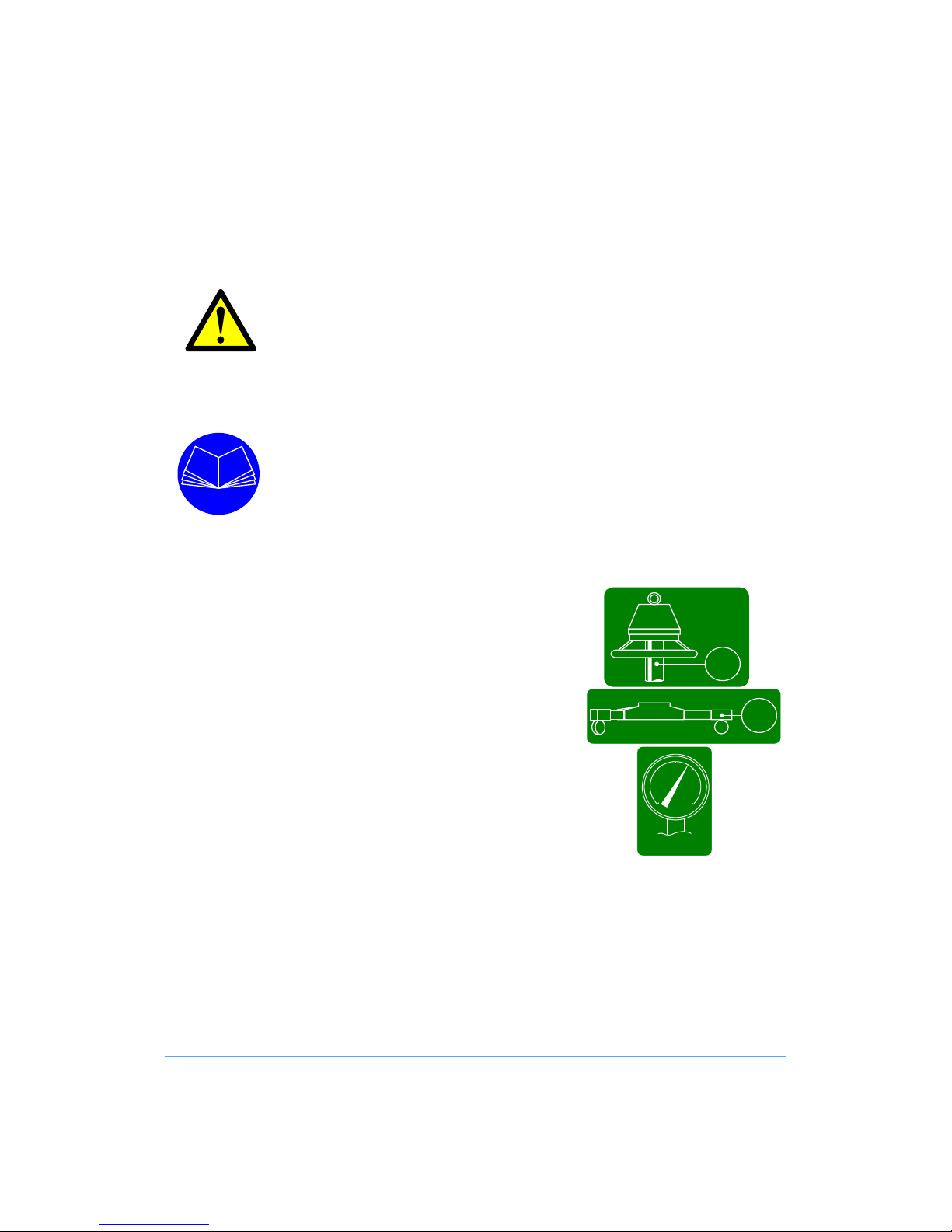
Warning symbols on the pedestal
On encountering the warning triangle and open book symbols it is imperative
that you consult this operators guide before using this pedestal or attempting
any adjustment or repair.
Critical data
Mass
Column (including steering ring)18.5 kg (40 lb)
Trim weights (6 off) total 3 kg (6.6 lb)
Skid (including kick bar) 21 kg(46 lb)
Load
Maximum load 90 kg (198 lb)
Pressure
Maximum pressure 11.3 bar (165 psi)
≤11.3 bar
18.5
kg
<90 kg
21
kg
Page 4

4
Usage
The Osprey Plus Single-Stage Pedestal is designed for use in television studios and on location
to support a pan and tilt head, camera and ancillary equipment weighing up to 90 kg (198 lb)
The Osprey Plus Single-Stage Pedestal is intended for use by television camera operators.
Further information
For further information or advice regarding this pedestal, please contact Vinten Broadcast Limited,
your local Vinten distributor or visit our website.
For full details on maintenance and spare parts, please refer to the Osprey Plus Single-Stage
Maintenance Manual and Illustrated Parts List - Publication Part No. 3323-9, obtainable from Vinten Broadcast Limited or your local Vinten distributor. For information on-line, visit our website at
www.vinten.com.
WARNING! If you do not understand how to operate this pedestal, do not
attempt to use it.
Maintenance beyond that detailed in this Operators Guide must
be performed only by competent personnel in accordance with
the procedures laid down in the Maintenance Manual.
Page 5

5
Contents
Page
Safety - read this first . . . . . . . . . . . . . . . . . . . . . . . . . . . . . . . . . . . . . . . . . . . . . . . . . . . . . . . . 3
Critical data . . . . . . . . . . . . . . . . . . . . . . . . . . . . . . . . . . . . . . . . . . . . . . . . . . . . . . . . . . . . . . . . 3
Usage . . . . . . . . . . . . . . . . . . . . . . . . . . . . . . . . . . . . . . . . . . . . . . . . . . . . . . . . . . . . . . . . . . . . . 4
Further information. . . . . . . . . . . . . . . . . . . . . . . . . . . . . . . . . . . . . . . . . . . . . . . . . . . . . . . . . . 4
Introduction. . . . . . . . . . . . . . . . . . . . . . . . . . . . . . . . . . . . . . . . . . . . . . . . . . . . . . . . . . . . . . . . 8
Operation
Assembling the pedestal . . . . . . . . . . . . . . . . . . . . . . . . . . . . . . . . . . . . . . . . . . . . . . . . . . . . 9
Pressurizing the pedestal . . . . . . . . . . . . . . . . . . . . . . . . . . . . . . . . . . . . . . . . . . . . . . . . . . 10
Fitting and balancing the load . . . . . . . . . . . . . . . . . . . . . . . . . . . . . . . . . . . . . . . . . . . . . . . 10
Using the Osprey Plus pedestal
Height adjustment. . . . . . . . . . . . . . . . . . . . . . . . . . . . . . . . . . . . . . . . . . . . . . . . . . . . . . 11
Brakes. . . . . . . . . . . . . . . . . . . . . . . . . . . . . . . . . . . . . . . . . . . . . . . . . . . . . . . . . . . . . . . 11
Cable guards . . . . . . . . . . . . . . . . . . . . . . . . . . . . . . . . . . . . . . . . . . . . . . . . . . . . . . . . . 11
Steering . . . . . . . . . . . . . . . . . . . . . . . . . . . . . . . . . . . . . . . . . . . . . . . . . . . . . . . . . . . . . 11
Steering tiller. . . . . . . . . . . . . . . . . . . . . . . . . . . . . . . . . . . . . . . . . . . . . . . . . . . . . . . . . . 12
Changing the skid tracking width . . . . . . . . . . . . . . . . . . . . . . . . . . . . . . . . . . . . . . . . . . 13
Optional wheels . . . . . . . . . . . . . . . . . . . . . . . . . . . . . . . . . . . . . . . . . . . . . . . . . . . . . . . 14
Transportation and storage . . . . . . . . . . . . . . . . . . . . . . . . . . . . . . . . . . . . . . . . . . . . . . . . . 14
Servicing
General . . . . . . . . . . . . . . . . . . . . . . . . . . . . . . . . . . . . . . . . . . . . . . . . . . . . . . . . . . . . . . . . 16
Cleaning. . . . . . . . . . . . . . . . . . . . . . . . . . . . . . . . . . . . . . . . . . . . . . . . . . . . . . . . . . . . . . . . 16
Routine checks . . . . . . . . . . . . . . . . . . . . . . . . . . . . . . . . . . . . . . . . . . . . . . . . . . . . . . . . . . 16
Adjustments
Skid clamp adjustment . . . . . . . . . . . . . . . . . . . . . . . . . . . . . . . . . . . . . . . . . . . . . . . . . . 17
Elimination of radial and side play in the moving column. . . . . . . . . . . . . . . . . . . . . . . . 17
Parts list. . . . . . . . . . . . . . . . . . . . . . . . . . . . . . . . . . . . . . . . . . . . . . . . . . . . . . . . . . . . . . . . . . 18
Technical data . . . . . . . . . . . . . . . . . . . . . . . . . . . . . . . . . . . . . . . . . . . . . . . . . . . . . . . . . . . . . 19
Associated Publications
Osprey Plus Single-Stage
Maintenance Manual
Part No. 3323-9
Page 6

6
Osprey Plus Single-Stage Pedestal
(1)
(2)
(3)
(4)
(6)
(7)
(8)
(9)
(25)
(24)
(14)
(19)
(18)
(17)
(13) (12)
(23)
(5)
(20)
(10)(11)(15)(16)
(22)
(21)
Page 7

7
Osprey Plus Single-Stage Pedestal
(1) Four-bolt mounting plate
(2) Pressure gauge
(3) Steering indicator
(4) Moving column
(5) Safety Catch
(6) Trim weight stowage
(7) Short strut
(8) Foot support and strap
(9) Wheel brake foot-button
(10) Kick bar
(11) Skid clamp
(12) Fixed column
(13) Trim weight
(14) Crab/steer changeover foot-button
(15) Cable clamp
(16) Cable guard
(17) Tiller socket
(18) Velcro strap
t(19) Long strut
(20) Drag control
(21) Top clamp
(22) Schrader valve and cap
(23) Removable steering ring
(24) Steering ring mounting plate
(25) Weight tray
Page 8

8
Introduction
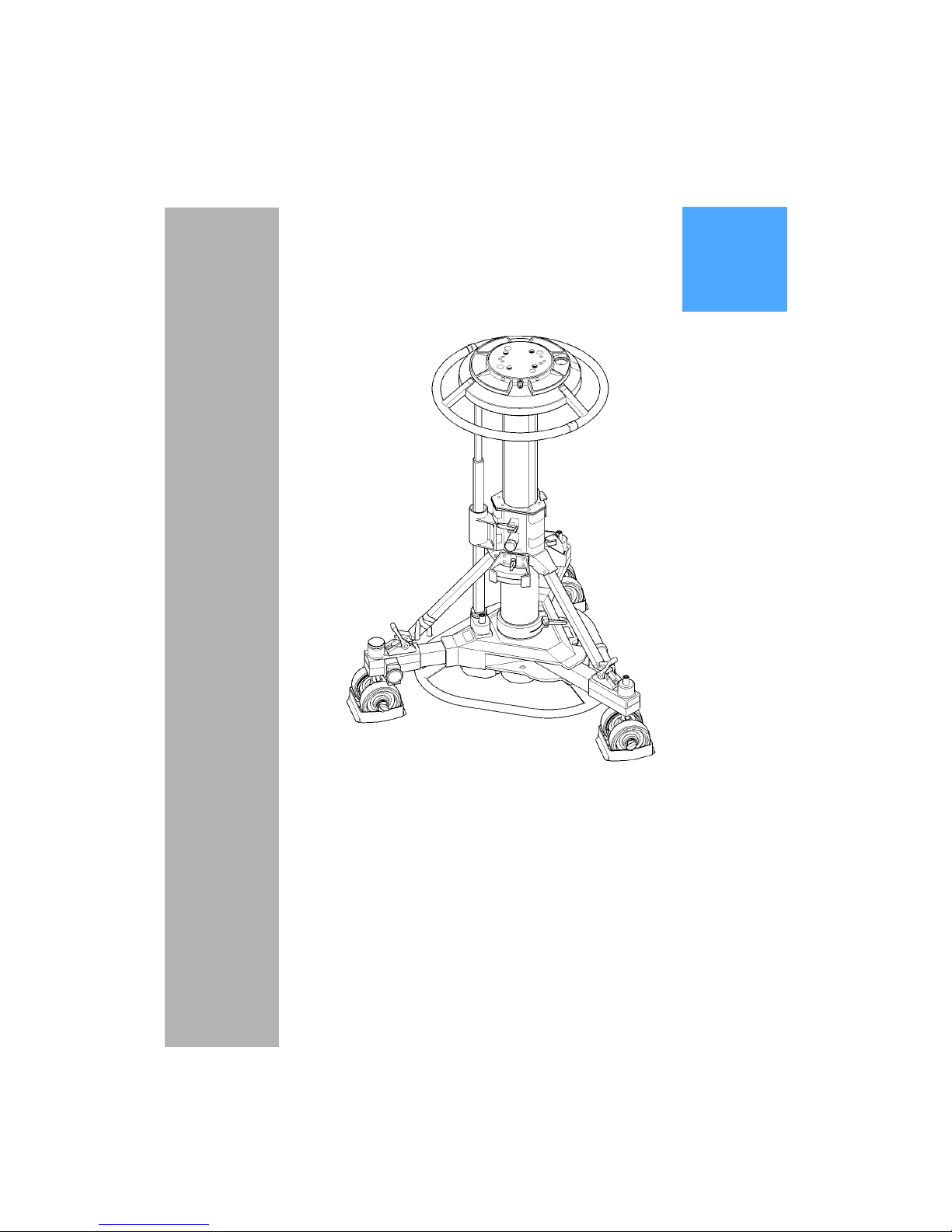
The Osprey Plus single-stage pedestal comprises a central telescopic column and a steerable,
folding skid assembly. For transport and storage the column and skid may be separated.
The moving column (4) is pressurized from an external pressure source. Balance is achieved with
approximately 1.26 bar pressure for every 10 kg of load (10 psi for every 13 lb). Trim weights (13)
are provided for fine balance.
The skid comprises a centre casting with carrying handle, a fixed leg and two folding legs. Each
leg carries twin wheels, with brakes (9) on the folding legs and a tiller socket (17) on the fixed leg.
Two versions of the skid are available. The OB skid has 160 mm (6.3 in.) wheels. The studio skid
has 125 mm (5 in.) wheels with cable guards (16). The Vinten heavy-duty tracking skid, designed
for use on 620 mm track, may also be used with the Osprey Plus pedestal.
Page 9

9
Operation
Assembling the pedestal
Turn the skid upside-down, depress the leg locking plungers and swing each folding leg out until
the plungers lock the legs in the fully open position (See Changing the skid tracking width).
Fit the kick bar (10), which is secured by three sliding catches on the underside of the centre casting.
Set the skid on the ground on its wheels and apply the brakes (9).
Install the column on the skid as follows:
Ensure that the rubber straps on each foot support (8) are to the outside of the ball joint.
Hold the column upright and release the Velcro retaining strap (18) holding the three struts.
Raise the longer strut (19) to about 30° from horizontal. The strut joint is adjusted to retain
the strut in this position.
Lift the column, holding the two shorter struts (7) out from the column. Align the longer strut
(19) with the fixed leg of the skid and carefully lower the column base into the skid centre.
Ensure that the struts engage with the ball joints on each foot support and the steering tube
locates in its socket.
Secure the struts to the supports with the rubber straps (8).
Tighten the skid clamp (11), using moderate hand pressure only. The clamp lever has a
spring-loaded ratchet-type action and is operated as follows:
Turn the clamp lever clockwise as far as possible.
Pull the lever outward against the spring pressure, return it to vertical and release.
Turn lever clockwise again.
Repeat until the skid clamp is sufficiently tightened.
Secure the Velcro retaining strap (18) clear of the skid wheels.
Slide the steering indicator(s) (3) to the desired position (See Steering).
If the pedestal is already pressurized, the load may now be fitted. Otherwise pressurize the pedestal before fitting the load.
Page 10

10
Pressurizing the pedestal
The Osprey Plus is pressurized from an external source.
A correctly pressurized pedestal will balance its payload such that it can be moved to any position
over the full on-shot stroke of the moving column, with minimum effort, and it will maintain its position when the steering ring is released. Balance is achieved with approximately 1.26 bar pressure for every 10 kg of load (10 psi for every 13 lb).
To pressurize the pedestal, proceed as follows:
Push down on the steering ring (23) against any residual pressure and release the safety
catch (5). Move the slide to the OFF (O) position.
Remove the Schrader valve cap (22) and connect the charging line from the pressure
source.
Turn on the pressure supply and slowly increase the pedestal pressure. If not already fully
extended, the moving column (4) will rise. Shut off the supply when maximum working pressure is reached, indicated by the leading edge of the red sector on the gauge (2).
Disconnect the charging line, but do not refit the Schrader valve cap at this stage.
Install the camera mount and payload and balance the load.
Fitting and balancing the load
After pressurization of the pedestal, the camera mounting and payload can be fitted and balanced.
The Osprey Plus pedestal has the standard four-bolt mounting plate (1) which permits the use of
various Vinten camera mounts including pan and tilt heads, Quickfix and Mitchell adapters. The
mounting bolts are captive in the pedestal and the bolt heads are accessible from the underside
of the mounting plate. When the camera mount has been fitted, the bolts should be tightened securely using a flat- bladed screwdriver or a spanner of the correct size. A Vinten spanner, Part No.
J551-001, is available for this purpose.
WARNING! This pedestal must be pressurized only with clean, dry air or
nitrogen. A pressure reducing valve must be fitted to the pressure line between the gas cylinder and the outlet connection of
the hose. The reducing valve must be screwed into the gas cylinder outlet. The maximum pressure on the outlet side of the
reducing valve must not exceed 11.3bar (165psi). Do not pressurize the pedestal beyond the maximum safe working pressure
indicated by the leading edge of the red sector on the gauge.
The pedestal is fitted with a pressure relief valve as a safeguard
against over- pressurization.
Do not attempt to adjust the pressure relief valve
WARNING! A pressurized pedestal will rise rapidly when safety catch is
released. Do not lean over the pedestal when releasing the
safety catch. Always restrain the pedestal by hand pressure on
the steering ring when the safety catch is released.
Page 11

11
When the camera mount has been secured proceed as follows:
Fit the payload to the fully-extended top stage of the pedestal, ensuring that all items such
as pan bars, prompters, lenses etc, are fitted. Attaching these items at a later stage may
upset the pedestal balance. Install three trim weights (13) on the weight tray (25).
Using the Schrader valve cap (22), carefully reduce the pressure in steps of 0.15-0.20 bar
(2-3 psi) until the payload is correctly balanced.
A correctly pressurized pedestal will balance its payload such that it may be moved to any
position over the full on-shot stroke with minimum effort and will maintain its position when
the steering ring is released.
Fine balance may be achieved by adding or removing trim weights (13).
Disconnect the charging line, but do not refit the Schrader valve cap at this stage.
Using the Osprey Plus pedestal
Height adjustment
The column has an on-shot stroke of 510 mm (21.0 in.) and the load can be moved over this distance, in perfect balance, by raising and lowering the steering ring (23). The movement is adjustable for drag and this is set according to operator preference by means of the drag control (20)
located at the top of the fixed column (12). Turn the control clockwise to increase the drag setting,
and counter-clockwise to decease it.
A clamp (21) can be used to hold the moving column in position if fixed height operation is required. Move the clamp lever fully to the left to apply the clamp. Move it fully to the right to release
the clamp.
Brakes
The skid is fitted with brakes on the wheels on the folding legs. The brakes are operated by pressing on the foot-buttons (9) located above the wheels. Press once to apply the brake and again to
release it.
Cable guards
The cable guards (16) fitted to the studio version are height-adjustable and should be set as re-
quired. Adjustment is carried out by slackening the knobs, setting the cable guards at the required
height and re-tightening the knobs.
Steering
Directional control of the pedestal is achieved by turning the steering ring (23) mounted at the top
of the column. The steering system is geared so that the skid wheels turn by the same amount as
the steering ring. This ensures, for example, that with the pedestal set to crab, turning the steering
ring by 90° will also cause the pedestal to change direction by 90°. The steering ring is fitted with
two movable indicators (3) which can be used to mark the straight-ahead position of the ring and
will thus provide a reference point when steering.
WARNING! The Schrader valve cap (22) forms a primary pressure seal.
Always replace the cap and screw it down finger-tight.
Page 12
12
The skid has a crab/steer arrangement with a foot-operated changeover mechanism, which provides a steer setting i.e. one wheel steering, two fixed; or a crab setting, where all three wheels
turn together. Pushing the foot-button (14) operates a changeover mechanism which toggles the
pedestal between crab and steer. Although the button can be pressed with the wheels in any position, the changeover will not occur until the wheels are all facing forward, so the steering ring
may have to be turned by up to 180° before the changeover mechanism engages. This arrangement ensures that the rear wheels will always lock in the straight-ahead position when changing
from crab to steer.
A clutch in each wheel unit disconnects that wheel from the steering in the event of the wheel striking an obstacle. To reconnect the wheel, hold the steering ring stationary and turn the wheel unit
until the clutch re-engages.
Steering tiller
The steering tiller (Part No. 3329-21) provides an alternative means of steering the skid. It is particularly useful when the skid is fitted with a head-to-skid adapter or fixed column, or when a grip
or assistant is required to manoeuvre the pedestal.
The tiller is fitted as follows:
Unscrew and remove the round cap (17) which is fitted on the tiller socket on the end of the
fixed skid leg. The cap may be used to close the steering tube socket if the skid is used
without the column installed.
Fit the tiller bar in the tiller socket and engage it with the drive dog.
The pedestal can now be steered by turning the tiller bar or steering ring. Crab/steer
changeover is carried out in the usual manner.
Skid Tracking Width
1
22
1
Page 13
13
Changing the skid tracking width
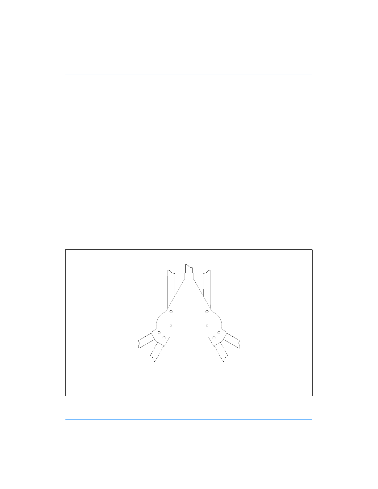
The movable skid legs can be set to either of two positions. Position 1 is for normal use and gives
maximum stability. Position 2 provides a reduced width for tracking through narrow doorways etc.
To change the tracking width:
Set the column to its lowest setting and engage the safety catch (5).
Ensure that the brakes (9) are released and then turn the skid wheels so they are pointing
at right angles to the skid legs.
Reach under the pedestal, depress one of the spring-loaded locking plungers and move the
leg to the required position, ensuring that the plunger has engaged correctly at the new location.
Repeat for the second leg.
WARNING! To ensure maximum stability when the skid is set to narrow
track, particularly when moving over uneven ground, reduce
pedestal height to a minimum
Optional Wheels
(26.1)
(26.2)
(26.1)
(26.3)
Page 14

14
Optional wheels
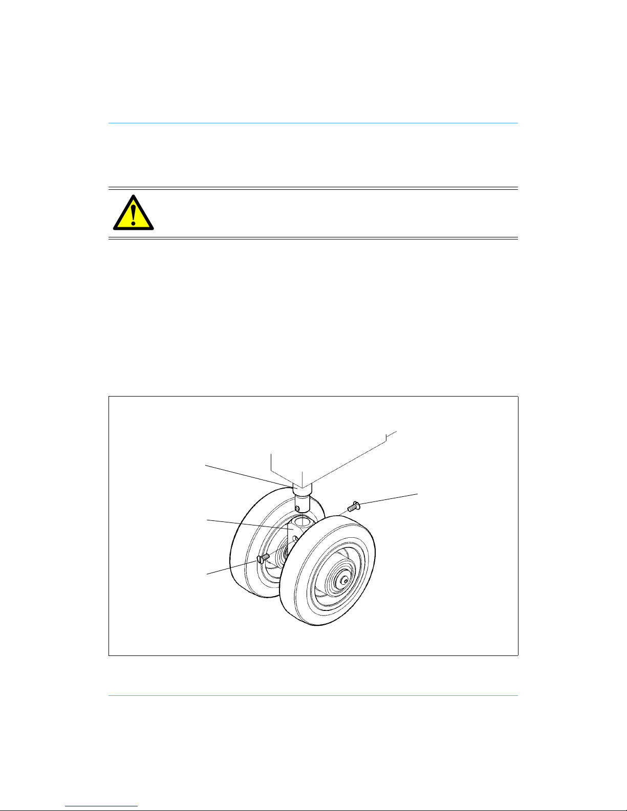
A set of 160 mm (6.3 in.) wheels (Part No. 3329-30) is available to convert the skid from studio to
OB use. A set of 125 mm (5in.) wheels with cable guards (Part No. 3329-43) is available to convert
an OB skid to a studio skid.
To replace the wheels:
Remove the column from the skid and turn the skid upside-down.
Unscrew and remove the countersunk screws (26.1) securing the wheel assembly (26.2) to
the shaft (26.3).
Remove the wheel assembly, complete with cable guard.
Repeat for remaining two wheel assemblies. Store the wheels for future use.
Fit the replacement wheel assemblies (26.2) to the shafts (26.3) and secure each wheel assembly to the shaft with the countersunk screws (26.1).
Transportation and storage
The pedestal may be dismantled for transportation and storage. Proceed as follows:
Apply the brakes (9).
Remove the load and secure any trim weights (13) in the trim weight stowage (6).
Set the safety catch slide (5) to ON (I) and fully depress the column until the safety catch
engages.
Release the skid clamp (11).
Release the three rubber foot straps (10) from the struts.
Raise the longer strut (19)(on the fixed skid leg), which will remain raised when released.
Raise and hold the two shorter struts (7), then lift the complete column vertically off the skid.
WARNING! Local, national or international regulations may apply to the
transport and storage of pressurized pedestals.
NOTE: It is not necessary to reduce the pedestal pressure prior to transportation or
storage and the pan and tilt head may be removed with the pedestal in the fully
depressed and locked position. However, to facilitate removal of the camera and
mounting, pressure should be reduced to 3.5 bar (50 psi).
WARNING! Ensure that the payload is removed and trim weights are
secured in the trim weight stowage before dismantling the pedestal.
Page 15

15
Secure the struts with the Velcro strap (18).
Remove the steering ring (23) by unscrewing each fastener until it releases. Lift the steering
ring off its mounting plate (24).
Remove the kickbar (10) from the skid by releasing the sliding catches
Depress the locking plungers and fold the skid legs, ensuring that the plungers lock in the
fully closed position
WARNING! The column will be unstable if stood on its base.
Page 16

16
Servicing
General
The Osprey Plus pedestal is robustly made to high engineering standards and little attention is
required to maintain serviceability save regular cleaning. Attention to the following points will ensure a long and useful service life with minimum need for repair.
Cleaning
During normal studio use, the only cleaning required should be a regular wipe over with a lint-free
cloth. Dirt accumulated during storage or periods of disuse may be removed with a semi-stiff
brush. Particular attention should be paid to the flats on the top stage of the column.
Use out-of-doors will require special attention, especially in adverse conditions. Salt spray must
be washed off with fresh water at the earliest opportunity. Do not allow water to enter the column.
Sand and dirt acts as an abrasive and should be removed with a semi-stiff brush or vacuum cleaner.
Routine checks
Check the following during normal use:
Check for ageing and cracking of the rubber strut securing straps and renew if necessary.
Check the effectiveness of the clamps.
Check for radial or side play in the moving column.
Adjustments
Adjustments that may become necessary after considerable use are as follows:
Taking up wear In the skid clamp.
Elimination of radial and side play in the moving column.
NOTE: Do NOT use oil or grease on any exposed part of the column. This is
unnecessary and traps dirt which acts as an abrasive.
NOTE: Use only detergent-based cleaners. Do NOT use solvent- or oil-based cleaners,
abrasives or wire brushes to remove accumulations of dirt, as these damage the
protective surfaces.
Page 17
17
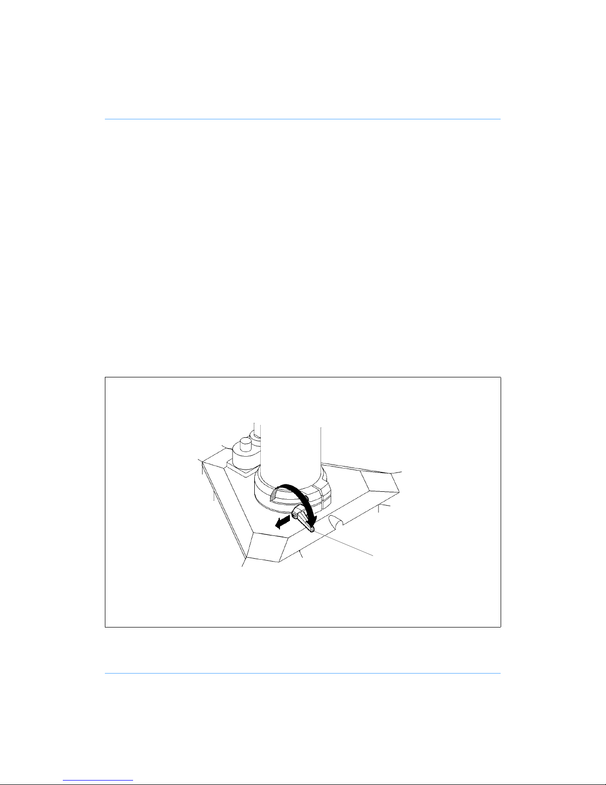
Skid clamp adjustment
To adjust the skid clamp:
The skid clamp (11) is applied or released by turning the handle clockwise or counter-clockwise. The handle has a pull-off/push-on ratchet adjustment. To take up wear, pull the handle away from the spindle, rotate counter-clockwise and release.
Repeat the above procedure, as necessary, until the clamp locks when applied but allows
free movement when released.
Elimination of radial and side play in the moving column.
If excessive radial or side play is apparent in the moving column, refer to the appropriate section
in the Maintenance Manual. This adjustment should be carried out by a competent person.
Skid Clamp Adjustment
(11)
Page 18

18
Parts list
The following lists include main assemblies, user-replaceable spare parts and optional accessories. For further information regarding repair or spare parts, please contact Vinten Broadcast Ltd
or your local distributor.
For information on-line, visit our website at
www.vinten.com.
Item Part No.
Osprey Plus OB version (160 mm wheels) 3323-3B
Osprey Plus studio version (125 mm wheels and cable guards) 3323-3C
Column 3323-11
OB skid 3329-3B
Studio skid 3329-3C
Heavy-duty tracking skid 3369-50
Kick bar 3329-32
Trim weight 3328-328
Spanner for head bolts J551-001
Steering tiller 3329-21
Column for fitting to Penguin dolly 3326-20
Fixed column for use with Dolphin arm 3348-3
Short column assembly 3352-3
Low-level adaptor (four-bolt fixing) 3368-24
Set of three OB wheels 3329-30
Set of three studio wheels with cable guards 3329-43
Page 19

19
Technical data
Studio OB
Payload 90 kg (198 lb) 90 kg (198 lb)
Column weight 18.5 kg (40 lb) 18.5 kg (40 lb)
Skid weight 21 kg (47 lb) 21 kg (47 lb)
Trim weights (6 off - total) 3 kg (6.6 lb) 3 kg (6.6 lb)
Total pedestal weight 42.5kg (93.5lb) 42.5k (93.5lb)
Minimum height 71 cm (28 in.) 74 cm (28 in.)
Maximum height 122 cm (48 in.) 125 cm (48 in.)
On-shot stroke 51 cm (20 in.) 51 cm (20 in.)
Skid leg radius 48 cm (19 in.) 48 cm (19 in.)
Doorway tracking width 97 cm (38 in.) 97 cm (38 in.)
Transit doorway width 86 cm (34 in.) 86 cm (34 in.)
Narrow doorway width 70 cm (27.5 in.) 70 cm (27.5 in.)
Wheel diameter 125 mm (5 in.) 160 mm (6.3 in.)
Steering ring diameter 53.5 cm (21 in.) 53.5 cm (21 in.)
Max working pressure 11.3 bar (165 psi) 11.3 bar (165 psi)
Relief valve pressure 13.4 bar (195 psi) 13.4 bar (195 psi)
 Loading...