

Page 1

HS-105P, PE. SA
AutoCam™ Pan & Tilt Head
Operation, Installation
And Maintenance
(pn AB-300108 for sn 14xxxx0000 - 100799)
i
Page 2
HS-105P Pan & Tilt Head
Safety
IMPORTANT!: Read the Safety Section starting on page 1-2
before installing or using this equipment, or attempting any
adjustment or repair. This safety triangle is used in the manual to
indicate important information. Readthis information carefully to
avoid the risk of personal injury, injury to others, or damage to the equipment.
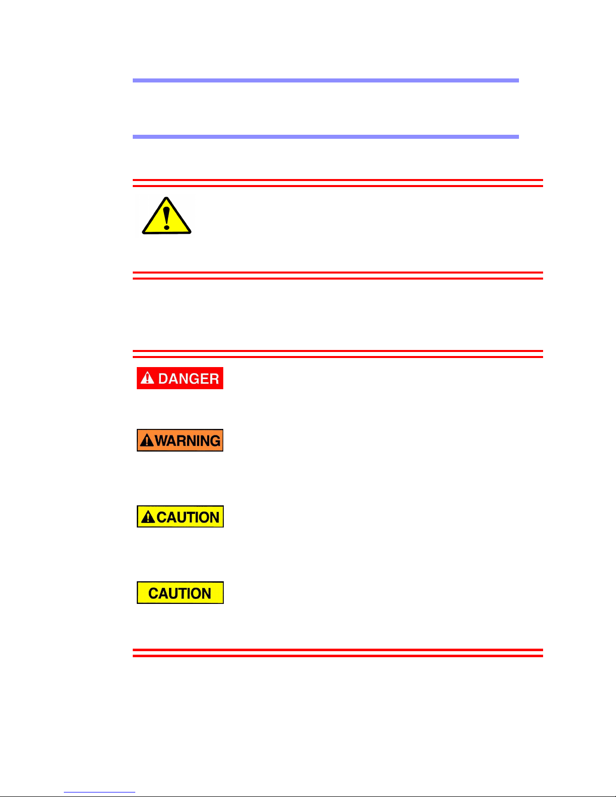
Warning Labels
Various colored safety labels are attached to the AutoCam equipment to alert you to
hazardous situations. The labels and their meaning are described below.
DANGER (with a red background) indicates an imminently
hazardous situation which, if not avoided, will result in death or serious injury.
WARNING (with an orange background) indicates a poten-
tially hazardous situation which, if not avoided, could result in death or serious
injury.
CAUTION(withayellowbackground) indicates a potentially
hazardous situation which, if not avoided, may result in minor or moderate
injury.
CAUTION(with a yellow background, but without the Safety
Alert symbol) indicates a potentially hazardous situation which, if not avoided,
may result in property damage.
ii
Page 3
Critical Data For HS-105P
Mass (Weight) 41 lb (18.6 kg)
Maximum Load 75 lb (34.0 kg)
(centered on tilt cradle)
Maximum Pressure Not Applicable
Input Voltage ± 28.5 V DC Nominal
Input Power ± 1.5 A Nominal
Date Of Manufacture 1999
iii
Page 4

Technical Support
If you are based in North, South or Central America and need technical support on
the AutoCam system, contact Vinten Inc. at:
709 Executive Blvd.
Valley Cottage, NY 10989
USA
Phone:1-888 4 VINTEN (1-888-484-6836) - Toll free in the U.S.A.
+1 845-268-0100
Fax:+1 845-268-0113
Or, if you are based outside of North, South or Central America, contact Vinten
Broadcast Limited at:
West er n Wa y
Bury St. Edmunds
Suffolk IP33 3TB
ENGLAND
Phone: +44 (0) 284 752121
Fax: +44 (0) 284 750560
iv
Page 5

Warranty
Vinten, Incorporated (Vinten) warrants that its equipment shall be free of defects in
material and workmanship for a period of twelve (12) months from the first date of
installation, but no more than eighteen (18) months from date of shipment, and is
extended only to the original purchaser. Vinten, at its option, will repair or replace
defective components. Warranty covers only those defects that occur when the equipment is used in the manner described in the Operation, Installation, and Service manual. Vinten’s liability is limited to parts, material, and labor necessary to repair or
replace equipment manufactured by Vinten. Any and all consequential damages are
excluded. Consumable supplies and normal wear items are the customer’s responsibility and are not covered by this warranty.
The warranty is in effect only when equipment is operated, adjusted, and maintained
in the manner described in the appropriate Operation, Installation, and Service manual. Modifications, service by non-authorized service personnel, failure to provide
proper maintenance, and abuse and misuse of the equipment will void the warranty.
Repairs not covered by this warranty will be billed for parts, labor, and expenses at
the rates in effect at the time of service.
Warranty service and repair will normally be performed at the Vinten factory in Valley Cottage, New York, but may, at the discretion of Vinten, be performed on the customer site. It is the customer’s responsibility to contact Vinten and obtain
authorization prior to returning equipment for warranty service. Returned equipment
must include a Return Material Authorization (RMA) number, and a failure report
describing the nature of the failure or complaint as well as the customer’s name,
address, and a contact name and phone number.
v
Page 6

Copyright
The Vinten Inc. AutoCam User Manual is copyrighted with all rights reserved. Under
the copyright law, this manual may not be copied, in whole or in part, without written
consent from Vinten Inc.
© 1999 by Vinten Inc.
Disclosure Statement - AutoCam System
This document contains information proprietary to Vinten Inc. Except by written
authorization from Vinten Inc., the information contained in this document shall not,
in whole or in part, be disclosed to third parties, reproduced for any purpose, or used
except for evaluation, operation and maintenance of equipment supplied by Vinten
Inc. or Vinten Broadcast.
Manual Outline
This manual covers the installation, operation and maintenance of the AutoCam HS105P Pan/Tilt Head. See Chapter 1 for a detailed description of the contents of this
manual.
Product Serial Numbers
Vinten AutoCam products are marked with unique serial numbers that include a 2
digit product identifier, a 4 digit serial number and a 2 character revision code. The
format is AABBBBXXCD where:
AA Product Identifier - 14 for the HS-105P
BBBB Serial number
XX Reserved for future use - currently 00
C Primaryrevisionstatus-0,1,2,3etc.
D Secondary revision status - 0, A, B, C etc.
This manual is applicable to products that have serial numbers 14xxxx0000 where
xxxx may be any 4 digit number.
AutoCamTM,VintenInc.TMand Lubricated Friction (LFTM) are trademarks of
Vinten Inc. or Vinten Broadcast Limited.
Specifications and features are subject to change without prior notice.
(100799)
vi
Page 7

Table Of Contents
HS-105P Pan & Tilt Head . . . . . . . . . . . . . . . . . . . . . . . . . . . . . . . . . ii
Safety . . . . . . . . . . . . . . . . . . . . . . . . . . . . . . . . . . . . . . . . . . . . . . . . ii
Warning Labels . . . . . . . . . . . . . . . . . . . . . . . . . . . . . . . . . . . . . . . . . . . . .ii
Critical Data For HS-105P . . . . . . . . . . . . . . . . . . . . . . . . . . . . . . . . . . . . iii
Technical Support . . . . . . . . . . . . . . . . . . . . . . . . . . . . . . . . . . . . . iv
Warranty . . . . . . . . . . . . . . . . . . . . . . . . . . . . . . . . . . . . . . . . . . . . . v
Copyright . . . . . . . . . . . . . . . . . . . . . . . . . . . . . . . . . . . . . . . . . . . . . . . . . vi
Disclosure Statement - AutoCam System . . . . . . . . . . . . . . . . . . . . . . vi
Manual Outline . . . . . . . . . . . . . . . . . . . . . . . . . . . . . . . . . . . . . . . . . . . . vi
Product Serial Numbers . . . . . . . . . . . . . . . . . . . . . . . . . . . . . . . . . . . . . vi
1 Safety & Introduction
Safety . . . . . . . . . . . . . . . . . . . . . . . . . . . . . . . . . . . . . . . . . . . . . . 1–2
Very Important Information . . . . . . . . . . . . . . . . . . . . . . . . . . . . . . . . 1–2
Customer Responsibility . . . . . . . . . . . . . . . . . . . . . . . . . . . . . . . . . . . 1–2
Safe Working Environment . . . . . . . . . . . . . . . . . . . . . . . . . . . . . . . . . 1–2
Operating Footprint And Safe Operating Zone . . . . . . . . . . . . . . . 1–3
Warning Signs . . . . . . . . . . . . . . . . . . . . . . . . . . . . . . . . . . . . . . . . . . . 1–3
Heads Can Start Unexpectedly . . . . . . . . . . . . . . . . . . . . . . . . . . . . 1–3
Power Switch . . . . . . . . . . . . . . . . . . . . . . . . . . . . . . . . . . . . . . . . . . . . 1–4
Pinch Points . . . . . . . . . . . . . . . . . . . . . . . . . . . . . . . . . . . . . . . . . . . . . 1–4
Sharp Edges . . . . . . . . . . . . . . . . . . . . . . . . . . . . . . . . . . . . . . . . . . . . . 1–4
Manual Outline . . . . . . . . . . . . . . . . . . . . . . . . . . . . . . . . . . . . . . 1–5
HS-105P Pan/Tilt Head . . . . . . . . . . . . . . . . . . . . . . . . . . . . . . . . 1–6
Key Features . . . . . . . . . . . . . . . . . . . . . . . . . . . . . . . . . . . . . . . . . . . . 1–6
HS-105P Specifications . . . . . . . . . . . . . . . . . . . . . . . . . . . . . . . . . . . . 1–7
HS-105SAPan/Tilt Head . . . . . . . . . . . . . . . . . . . . . . . . . . . . . . . . 1–8
HS-105PE Pan/Tilt Head . . . . . . . . . . . . . . . . . . . . . . . . . . . . . . . 1–9
Typical Applications . . . . . . . . . . . . . . . . . . . . . . . . . . . . . . . . . 1–10
Touch Screen Controller Systems . . . . . . . . . . . . . . . . . . . . . . . . . . 1–10
ACP 1–10
HCP 1–10
LCP 1–10
MultiController II System . . . . . . . . . . . . . . . . . . . . . . . . . . . . . . . . . . 1–10
2 Operation
Introduction . . . . . . . . . . . . . . . . . . . . . . . . . . . . . . . . . . . . . . . . . 2–2
vii
Page 8

3 Installation
Introduction . . . . . . . . . . . . . . . . . . . . . . . . . . . . . . . . . . . . . . . . . 3–2
Tools You Will Need . . . . . . . . . . . . . . . . . . . . . . . . . . . . . . . . . . . . . . . 3–2
Mechanical Installation . . . . . . . . . . . . . . . . . . . . . . . . . . . . . . . 3–4
Mounting The Pan & Tilt Head . . . . . . . . . . . . . . . . . . . . . . . . . . . . . . 3–4
Mounting And Balancing The Payload . . . . . . . . . . . . . . . . . . . . . . 3–4
Lens Drive Installation and Setup . . . . . . . . . . . . . . . . . . . . . . . 3–6
Minimizing Backlash . . . . . . . . . . . . . . . . . . . . . . . . . . . . . . . . . . . . . . 3–7
Pre-loading The Anti Backlash Gear 3–7
Follow Pot Adjustment . . . . . . . . . . . . . . . . . . . . . . . . . . . . . . . . . . . . 3–7
Focus 3–7
Zoom 3–8
Electrical Installation And Interconnection . . . . . . . . . . . . . . 3–10
Configuration . . . . . . . . . . . . . . . . . . . . . . . . . . . . . . . . . . . . . . . 3–12
Zoom/Focus Calibration . . . . . . . . . . . . . . . . . . . . . . . . . . . . . . . . . 3–12
Pan & Tilt Limits . . . . . . . . . . . . . . . . . . . . . . . . . . . . . . . . . . . . . . . . . 3–14
Pan Limit Switches 3–14
Tilt Limit Switches 3–16
Electrical Clip Limits 3–18
Other Jumpers . . . . . . . . . . . . . . . . . . . . . . . . . . . . . . . . . . . . . . . . . . 3–24
Miscellaneous Functions - J3 3–24
J6 3–24
J9 3–24
Table Of Contents
HS-105SA Control Protocol . . . . . . . . . . . . . . . . . . . . . . . . . . . . 3–26
Talking To The HS-105SA . . . . . . . . . . . . . . . . . . . . . . . . . . . . . . . . . . 3–26
Listening To The HS-105SA . . . . . . . . . . . . . . . . . . . . . . . . . . . . . . . . 3–27
4 Maintenance And Repair
Introduction . . . . . . . . . . . . . . . . . . . . . . . . . . . . . . . . . . . . . . . . . 4–2
Service Philosophy . . . . . . . . . . . . . . . . . . . . . . . . . . . . . . . . . . . . . . . 4–2
Avoid Damage From Static Electricity . . . . . . . . . . . . . . . . . . . . . . . 4–2
Safety . . . . . . . . . . . . . . . . . . . . . . . . . . . . . . . . . . . . . . . . . . . . . . . . . . 4–3
Routine Maintenance . . . . . . . . . . . . . . . . . . . . . . . . . . . . . . . . . 4–4
Checking Balance . . . . . . . . . . . . . . . . . . . . . . . . . . . . . . . . . . . . . . . 4–4
Checking Overall Operation . . . . . . . . . . . . . . . . . . . . . . . . . . . . . . . 4–5
Theory Of Operation . . . . . . . . . . . . . . . . . . . . . . . . . . . . . . . . . . 4–6
Power Supply . . . . . . . . . . . . . . . . . . . . . . . . . . . . . . . . . . . . . . . . . . . . 4–6
Data Path . . . . . . . . . . . . . . . . . . . . . . . . . . . . . . . . . . . . . . . . . . . . . . 4–6
Circuit Theory . . . . . . . . . . . . . . . . . . . . . . . . . . . . . . . . . . . . . . . . . . . 4–6
viii
Page 9

Table Of Contents
Analog Servos 4–9
Digital Servos 4–9
Waveforms 4–9
Zoom/Focus Servo . . . . . . . . . . . . . . . . . . . . . . . . . . . . . . . . . . . . . . . 4–9
Head Indexing Procedure . . . . . . . . . . . . . . . . . . . . . . . . . . . . . . . . 4–10
Motor Drive Fuses . . . . . . . . . . . . . . . . . . . . . . . . . . . . . . . . . . . 4–12
Tilt Fuse Failure . . . . . . . . . . . . . . . . . . . . . . . . . . . . . . . . . . . . . . . . . . 4–12
Tilt Fuse Replacement . . . . . . . . . . . . . . . . . . . . . . . . . . . . . . . . . . . 4–12
Waveform Diagrams . . . . . . . . . . . . . . . . . . . . . . . . . . . . . . . . . 4–14
ix
Page 10

Table Of Contents
This page left blank intentionally.
x
Page 11

1 Safety & Introduction
User Manual 1-1
Page 12
HS-105P Safety & Introduction
Safety
Safety issues including important warnings, risks and related topics are covered
in this section of the manual. It is very important that this information be available to all personnel who will work on or near the Autocam equipment.
Very Important Information
To avoid personal injury, always exercise caution when working in the vicinity of energized heads as they can start to move
without any warning.
Unless it is impossible, you should always de-energize the
head before working on any part of the head, the camera/lens,
or any associated equipment.
Know the location of the HS-105P power On/Off switch so
that you can power down the head in an emergency.
Customer Responsibility
It is the customer’s responsibility to ensure that the workplace is safe. In normal
operation, the remote controlled heads and payloads in an Autocam system can
move suddenly and without warning. Since audible warnings are out of the
question in normal television applications, it is recommended that only trained
personnel be allowed to work in the active areas where the remote controlled
heads and payloads are located. As part of the training, personnel must be made
aware of the hazards of working in a robot environment, including the specific
hazards listed below. The forces are sufficient to cause personal injury, or injury
to others and therefore, caution is essential.
Safe Working Environment
Each of the remote control heads should be within the view of the operator of
the Autocam system at the control panel. Before and during remote operation,
the operator must verify visually that the active area is clear. If personnel are too
close to one of the heads that is about to move, the operator can prevent the
motion from starting, or stop the motion after it has started.
1-2 User Manual
Page 13
HS-105P Safety & Introduction
If the direct line of sight is obstructed in your installation, it is recommended
that one or more viewing cameras (e.g. security type cameras) are installed to
cover the active areas and allow the operator to view the entire work-space at all
times.
Operating Footprint And Safe Operating Zone
The operating footprint must take into account the overhang of any payload
equipment mounted on the HS-105P. In particular, the payload element that protrudes the most defines the operating footprint area as the head pans and tilts.
If your operating practices require personnel to work less than 3 feet (1m) outside the operating footprint, you must make sure that they are trained and are
aware of the hazards of working in a robot environment, including the specific
hazards listed below. The forces are sufficient to cause personal injury, or injury
to others and therefore, caution is essential.
Warning Signs
Warning signs should be displayed prominently in the workplace as a reminder
to trained personnel, and a primary warning to untrained personnel and visitors.
A typical sign might read:
WARNING:
Robotic heads and lenses move suddenly without warning
Keep a MINIMUM of 3 feet from active heads at all times
Heads Can Start Unexpectedly
The hazards associated with robotic camera systems are only slightly different
than those associated with operating a camera under conventional manual control. The speeds and camera weights are similar. The main difference is that with
automation, the operator is normally not near the cameras, and it is more difficult to verify that the area is clear. For personnel working on or near the robotic
heads, they must be aware that the equipment can start moving unexpectedly.
All personnel should be trained and aware of the hazards of robotic heads, and
the fact that they can move at any time. They must be trained on how far the
heads and payloads can move, the speeds involved, and the need to stay back an
appropriate distance.
Most adjustments to the camera and head, such as tilt balancing and camera
video adjustments, should be made with the system de-energized. However, if
adjustments are absolutely necessary while the head is powered, they should
only be made by trained technical personnel familiar with the AutoCam robotics
system. They must understand that the camera can move unexpectedly at any
time, and must position themselves so that any motion would not cause them
personal harm.
User Manual 1-3
Page 14
HS-105P Safety & Introduction
When the robotic heads move, the speeds involv e d are fairly slow. However , the
equipment is still capable of generating sufficient force to cause injury. Therefore, it is essential that you exercise caution.
Any failure of the system could possibly cause one or more axes to move on
their own, but the speeds and forces should not be noticeably greater than those
encountered during normal use.
Power Switch
If you need to disable a head in an emergency, or for any other reason, use the
Power Switch on the head.
After clearing the cause for the emergency, or completing the maintenance task,
turn the Power Switch back on.
Pinch Points
Particular care should be exercised around possible points where you could get
pinched, such as the tilt cradle. Here, the forces can be somewhat greater, due to
the short lever arm.
Sharp Edges
If the lens, or other camera attachments have sharp edges that could cause
injury, make sure they are padded or protected.
1-4 User Manual
Page 15

HS-105P Safety & Introduction
Manual Outline
Chapter 1 This chapter discusses important safety issues
and provides an overview of the HS-105P,
HS-105SA and HS-105PE. Typical applications are described.
Chapter 2 Step by step instructions for operating the
HS-105P pan/tilt head.
Chapter 3 Step by step instructions for installing the
HS-105P pan/tilt head. Information specific
to the HS-105SA is also provided.
Chapter 4 Technical information including routine
maintenance, circuit descriptions, calibration, schematics and parts lists.
User Manual 1-5
Page 16
HS-105P Safety & Introduction
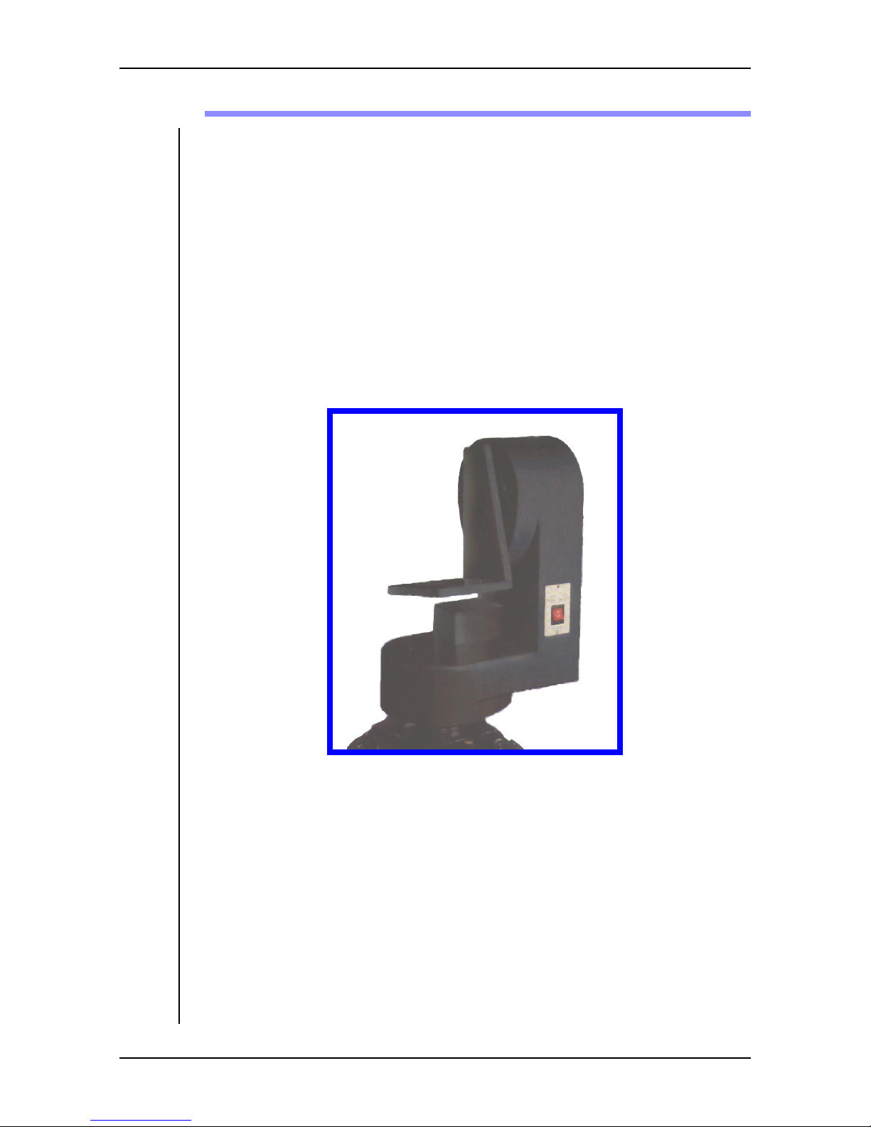
HS-105P Pan/Tilt Head
Key Features
• 75 lb. (34 kg.) payload capacity (centered on tilt arm)
• Ideal for portable camera/lens combinations
• Small profile
• High accuracy/speed
The HS-105P servo pan/tilt head is ideally suited to support a wide range of portable camera/lens combinations including a small teleprompter if applicable. Its
uses can include: following government proceedings; delivering distance learning between campuses; documenting scientific meetings; and much more.
The compact HS-105P can be mounted within existing wall cavities and the
camera platform is adjustable to provide perfect balance for your specific camera/lens combination. In addition, the head can be mounted on a pedestal or a
ceiling mount.
All of the head electronics are contained on a single circuit board for increased
reliability, and the high gain servos result in excellent acceleration (180o/sec2)
and smooth movement with 36 arc seconds position repeatability. This combined with an extremely rigid mechanical design allows tight damping without
oscillation or overshoot. Communication with the control panel is by RS-422
data over a maximum distance of 5000 ft. (1500 m). The HS-105P uses a slim
1-6 User Manual
HS-105P Pan/Tilt Head
Page 17

HS-105P Safety & Introduction
power/data cable which connects with a 2U rack mounted supply over a maximum distance of 500 ft. (150 m).
Control of zoom and focus is provided for full servo lenses, or the HP-ZFSLD
Lens Drive is attached to ENG lenses to provide the drive motors and follow
pots for servo operation.
The HS-105P can be controlled by all AutoCam controllers including the ACP/
HCP/LCP touch screen controllers and the MultiController II.
HS-105P Specifications
Weight 41 lb. (18.6 kg.)
Payload 75 lb. (34 kg.)
Pan Range 359°
Tilt Range ± 179°
(may be reduced by actual payload
and mounting configuration)
Accuracy 60 arc secs
Repeatability 36 arc secs
Angular Acceleration
180°/sec
2
Angular Velocity 60°/sec
Height 17.4” (44.1 cm)
Width 12.25” (31.1 cm)
Depth 7.0” (17.8 cm)
Mounting Tripod/Pedestal/Wall/Ceiling
Gear-train Type Self lubricating, anti-backlash
User Manual 1-7
Page 18

HS-105P Safety & Introduction
HS-105SAPan/Tilt Head
The SA version of the HS-105 is intended for applications where a custom controller will be used instead of an AutoCam controller. The protocol for controlling the SA version is described in Chapter 3 - Installation.
1-8 User Manual
Page 19

HS-105P Safety & Introduction
HS-105PE Pan/Tilt Head
The PE version of the HS-105 is a weather resistant model. It uses weather resistant connectors and does not have a power On/Off switch on the head.
User Manual 1-9
Page 20
HS-105P Safety & Introduction
Typical Applications
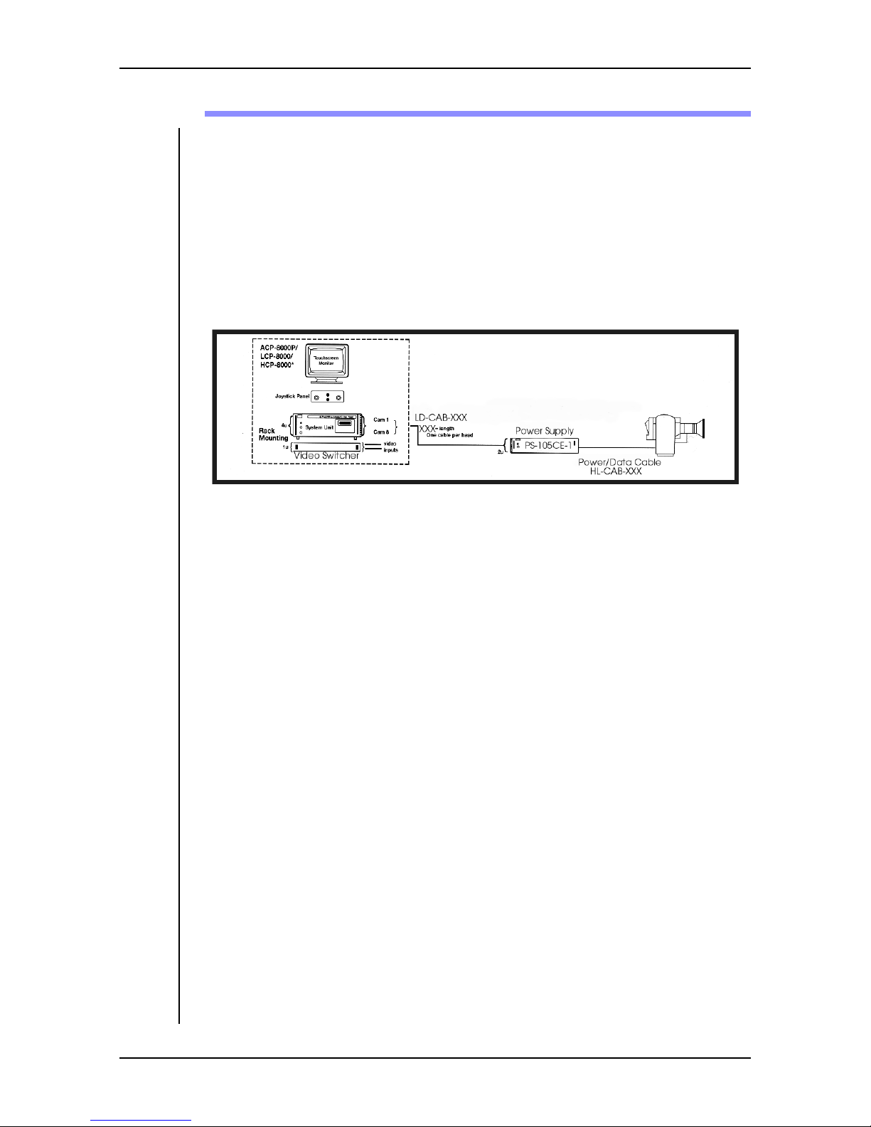
The HS-105P pan and tilt head can be controlled by one of the AutoCam touch
screen controllers or the MultiController II.
Refer to the User Manuals for your specific controllers for more information.
Touch Screen Controller Systems
Up to eight heads can be controlled by a single AutoCam touch screen controller
as shown below.
HS-105P
ACP
If the system includes one or more servo pedestals, the ACP controller is used.
HCP
The HCP is used when there are no servo pedestals in the system.
LCP
The LCP is customized for Legislative (and similar) applications.
MultiController II System
The compact MultiController II can control up to six HS-105P heads, or a combination of HS-105P and other AutoCam heads.
1-10 User Manual
Page 21

2 Operation
User Manual 2-1
Page 22

HS-105P Operation
Introduction
Apart from the power On/Off switch, the HS-105P has no external switches or
controls. Operating procedures for controlling the head remotely are described
in the User Manual for the specific controller in your installation.
2-2 User Manual
Page 23

3 Installation
User Manual 3-1
Page 24

HS-105P Installation
Introduction
This chapter covers the steps of mounting the heads, mounting and balancing
the cameras and configuring the system for operation.
For proper performance of the equipment and to prevent personal injury it is
critical that these procedures are followed.
Tools You Will Need
It is recommended that you have the following tools available during the
unpacking and installation:
• A set of SAE right angle hex keys
3-2 User Manual
Page 25

HS-105P Installation
This page left blank intentionally
User Manual 3-3
Page 26

HS-105P Installation
Mechanical Installation
For installations where the heads are frequently moved from location to location, a wedge plate and adapter may be used to attach the head to its mount contact Vinten Inc. for more information. Contact Vinten for other mounting
adapters if they are required for your installation.
Mounting The Pan & Tilt Head
Attach the HS-105P head to its mount using the three screws provided (1/4”-20)
and tighten them securely
Mounting And Balancing The Payload
For proper operation it is very important that the load is properly balanced
mechanically with the center of gravity set exactly on the tilt axis.
1. Start with the tilt cradle level.
2. Position the camera on the tilt cradle and attach with bolts through the tilt
cradle into the base of the camera. Leave the bolts just loose enough to be
able to slide the camera backwards and forwards.
3. Mount the lens on the camera (if it was not already installed).
4. Mount any other ancillary equipment such as tally lights etc.
5. Slide the camera back and forth until the overall payload feels balanced and
is centered about the tilt axis of the head. Tighten the bolts in the base of
the camera.
6. Check the balance after the bolts are tightened. If necessary, loosen the
bolts that hold the camera to the cradle and carefully push the payload in
the desired direction. Retighten the mounting bolts and check again for
proper balance. It is best to move the payload in small increments even
though this may require several steps until the balance is achieved.
7. Once the back and forth balance is achieved, proceed with adjustment of
vertical balance. Tilt the camera approximately 30 degrees upward and
release it. If the camera stays in the same position when released, the payload is properly balanced.
8. However, if the camera continues to move upwards after you let go, the
payload is mounted too high. On the other hand, if the camera moves back
towards the horizontal position when you let go, the payload is mounted
too low. Determine if you need to raise or lower the tilt cradle.
9. Mark the position of the camera on the tilt cradle so it can be re-installed in
the same position. Remove the camera from the tilt cradle.
10. Note or mark the vertical position of the tilt cradle to make sure that you
move it in the desired direction. Loosen the two 1/4-20 hex head screws
and raise or lower the cradle as necessary. Tighten the screws securely.
3-4 User Manual
Page 27

HS-105P Installation
11. Remount the payload and repeat step 7 to check the balance. Move the tilt
cradle again if necessary until balance is achieved.
User Manual 3-5
Page 28
HS-105P Installation
Lens Drive Installation and Setup
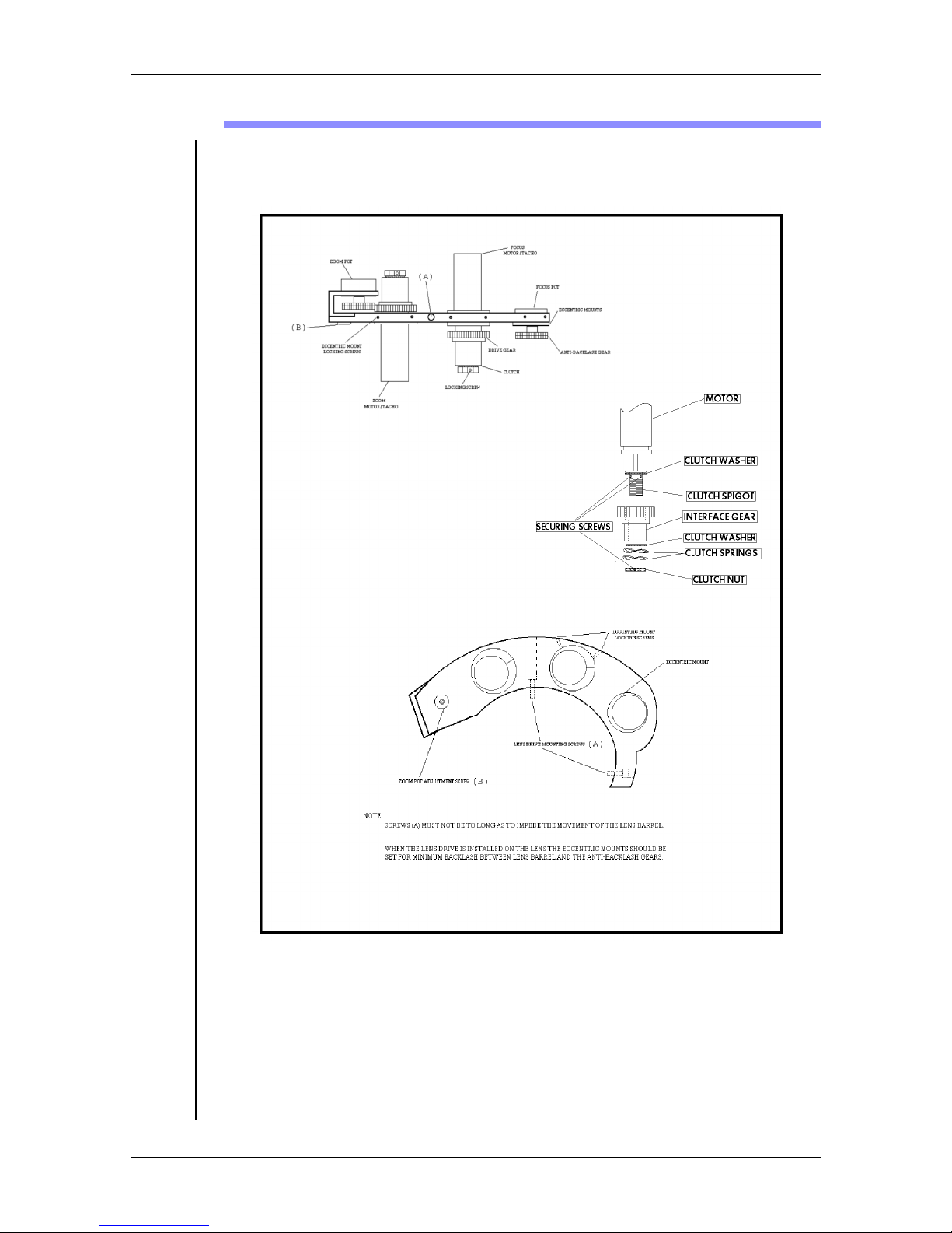
The servo lens drive assembly is shown below.
3-6 User Manual
ENG Lens Drive Assembly
Page 29

HS-105P Installation
Minimizing Backlash
It is a good idea when the lens drive is fitted (and periodically thereafter) to
adjust the eccentric mounts for minimum backlash. Advance the eccentric
mounts to remove any excess play between the gears. However, do not set the
mounts so close that the lens barrel is tight. Similarly, do not set the mounts so
loose that the lens servo is not repeatable. Find the happy medium. If you
remove the drive from a lens, and then re-mount it on the same lens, no adjustment should be necessary.
Pre-loading The Anti Backlash Gear
Before engaging the zoom and focus anti backlash gears with the lens, preload
the tension as follows: Viewing the gear from the bottom, preload the gear by 3
teeth in the clockwise direction. Hold the preloaded gear to maintain the tension
until it is f ully engaged with the lens.
Follow Pot Adjustment
The positional information in the lens servo comes from the zoom and focus
potentiometers. The wiper voltages provide the accurate feedback of position to
the servo. It is important therefore, that the pot wipers move within the center of
the pot’s travel for an end-to-end move of the lens. The method of adjustment is
described below, but note that the resistance values quoted are for reference
only, and may vary slightly from lens to lens. It is more important that the resistance values at each end of travel are symmetrical.
Focus
1. Switch the lens Manual/Servo lever to Manual.
2. Loosen the two fixing screws “A” sufficiently to allow the focus pot gear to
rotate free of the lens barrel, if required.
3. Measure the resistance of the focus pot pin #1 with respect to the wiper.
Rotate the lens barrel to the end of travel in the far focus direction - the
resistance should decrease. Lift the pot anti-backlash gear out of mesh and
rotate the gear for a resistance of 300 ohms. Re-engage the pot with the
lens focus barrel, advancing the ant-backlash gear by 2-3 teeth.
4. Connect the resistance meter to pin 3 with respect to the wiper. Rotate the
lens barrel to the end of travel in the near focus direction - the resistance
should decrease. Check that the resistance is approximately 300 ohms.
Repeat steps 3 and 4 until the resistance readings at each end of lens travel
are the same.
5. When symmetry is achieved, check that the anti-backlash gear is set correctly and tighten the two fixing screws “A”.
User Manual 3-7
Page 30

HS-105P Installation
Zoom
The anti-backlash gear on the zoom pot is meshed with the zoom motor gear. To
rotate the pot shaft, loosen screw “B” and slide the pot gear out of mesh.
1. Loosen fixing screw “B” sufficiently to allow the zoom pot gear to rotate
free of the zoom motor gear, if required.
2. Measure the resistance of the zoom pot pin #3 with respect to the wiper.
Rotate the lens barrel to the end of travel in the telephoto direction - the
resistance should decrease. Lift the pot anti-backlash gear out of mesh and
rotate the gear for a resistance of 300 ohms. Re-engage the pot with the
motor gear, advancing the ant-backlash gear by 2-3 teeth.
3. Connect the resistance meter to pin 1 with respect to the wiper. Rotate the
lens barrel to the end of travel in the zoom wide direction - the resistance
should decrease. Check that the resistance is approximately 300 ohms.
Repeat steps 2 and 3 until the resistance readings at each end of lens travel
are the same.
4. When symmetry is achieved, check that the anti-backlash gear is set correctly and tighten the fixing screw “B”.
3-8 User Manual
Page 31

HS-105P Installation
This page left blank intentionally.
User Manual 3-9
Page 32

HS-105P Installation
Electrical Installation And Interconnection
Installation instructions for the controller and associated equipment are provided
in the User Manual for your controller.
1. Before connecting AC power to any of the equipment, check the labels o n
each piece of equipment to make sure that it is the correc t voltage for your
installation (i.e. 110 or 220 volts).
2. Install the rackmount power supplies up to 500 ft. (150 m) from their
respective pan/tilt heads and connect AC power cables.
3. Connect the power/data cable from each power supply to its pan/tilt head.
4. Connect the cable from the lens drive assembly to the mating connector on
the HS-105P.
3-10 User Manual
Page 33

HS-105P Installation
This page left blank intentionally.
User Manual 3-11
Page 34
HS-105P Installation
Configuration
Zoom/Focus Calibration
The servo electronics in the head expects a certain voltage swing for maximum
travel of the lens. The following adjustments set the positive and negative voltages sent to the follow pots in the lens so that the feedback voltages from the
wipers are within the range expected. When the adjustments are completed, the
zoom and focus barrels should stop just short of their mechanical limits when
driven to their extremes using the zoom and focus controls on your controller.
1. Use a 3/32” hex key to remove the 7 screws in the HS-105P cover.
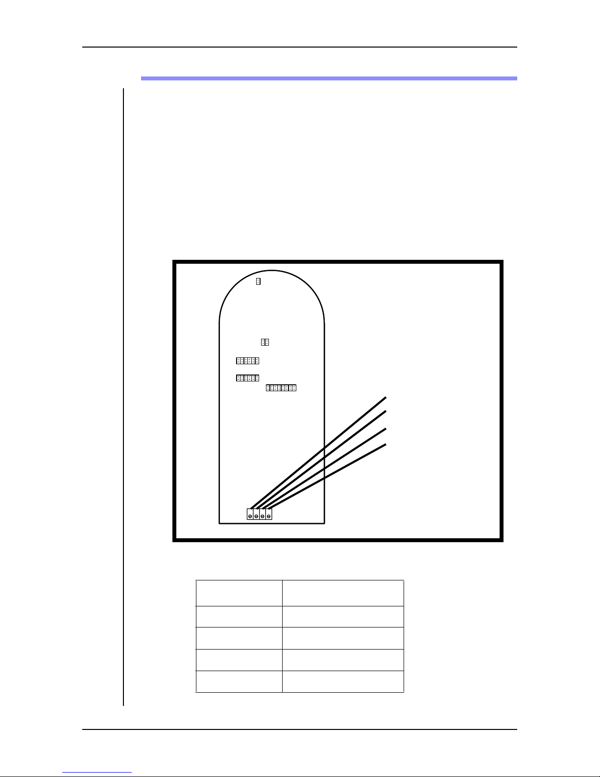
2. The diagram below shows the location of the lens calibration pots.
ZW - Zoom Wide
ZT - Zoom Tight
FN - Focus Near
FF - Focus Far
ZW ZT FN FF
3. Set the lens calibration pots to the following starting positions:
Pot Start Position
ZW Counter clockwise
ZT Clockwise
FN Clockwise
FF Counter clockwise
3-12 User Manual
Page 35

HS-105P Installation
4. Plug the lens into the connector on the head and power up the head.
5. Use the controller to drive the zoom to maximum wide angle (Zoom Wide)
and then adjust the ZW pot so that the lens barrel stops just short of the
mechanical end stop.
6. Use the controller to drive the zoom to maximum telephoto (Zoom Tight)
and then adjust the ZT pot so that the lens barrel stops just short of the
mechanical end stop.
7. Repeat steps 5 and 6 because there is some interaction between the two
controls.
8. Use the controller to drive the focus to maximum Far Focus and then adjust
the FF pot so that the lens stops just short of the mechanical end stop.
9. Use the controller to drive the focus to maximum Near Focus and then
adjust the NF pot so that the lens barrel stops just short of the mechanical
end stop.
10. Repeat steps 8 and 9 because there is interaction between the controls.
11. Set the pan and tilt limits as described in the next section. Or, replace the
cover and tighten the 7 screws with a 3/32” hex key.
User Manual 3-13
Page 36
HS-105P Installation
Pan & Tilt Limits
The HS-105P has a combination of mechanical and electrical limits for the pan
and tilt ranges. These are in addition to the clip limits that can be set if you are
using a touch screen controller. Microswitches in each of the motor drive wires
will open at predetermined positions and prevent further travel in that direction.
Diodes across the microswitches allow the head to be backed off from the limit
to re-close the switch that was open - see the HS-105P Wiring Diagram on
page 8 of Chapter 4. In addition to the limit switches, jumpers in the head are
used to set the electrical range of the servos. In most applications, the limit
switches are set to allow motion just slightly beyond the electrical range of the
servo. Thus, if there is a servo failure, the microswitches only allow the head to
travel slightly beyond the limits established by the jumpers.
Pan Limit Switches
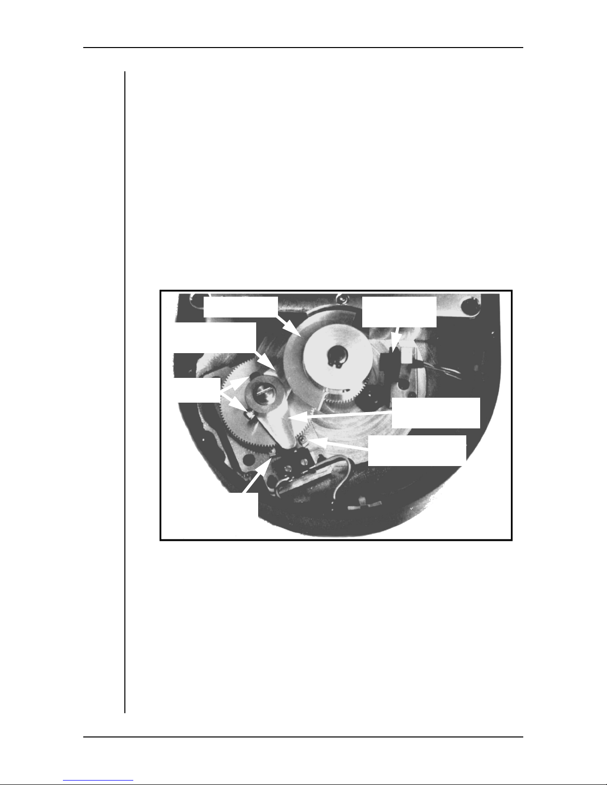
The pan limit switches and their respective cams are shown below.
Pan Shutter
Upper Cam
(CCW Pan Limit)
Cam Lock
Screws
CCW (Upper)
Switch Actuator
Pan Index
Optosensor
Lower Cam
(CW Pan Limit)
CW (Lower)
Switch Actuator
References to clockwise (CW) and counterclockwise (CCW) direc tions are as
viewed from above. To change the pan limit switch settings:
1. Use a 3/32” hex key to remove the 7 screws in the tilt motor cover.
2. With the controller turned off, turn the HS-105P head on and allow it to
complete the indexing routine. The pan and tilt shutters will be positioned
with an edge at their respective photosensors, and the head will be oriented
straight ahead and level.
3. Turn the head off. Viewing from above, manually pan the head in a
counter-clockwise direction - the pan limit cams will rotate clockwise stop when you reach the desired limit position.
3-14 User Manual
Page 37
HS-105P Installation
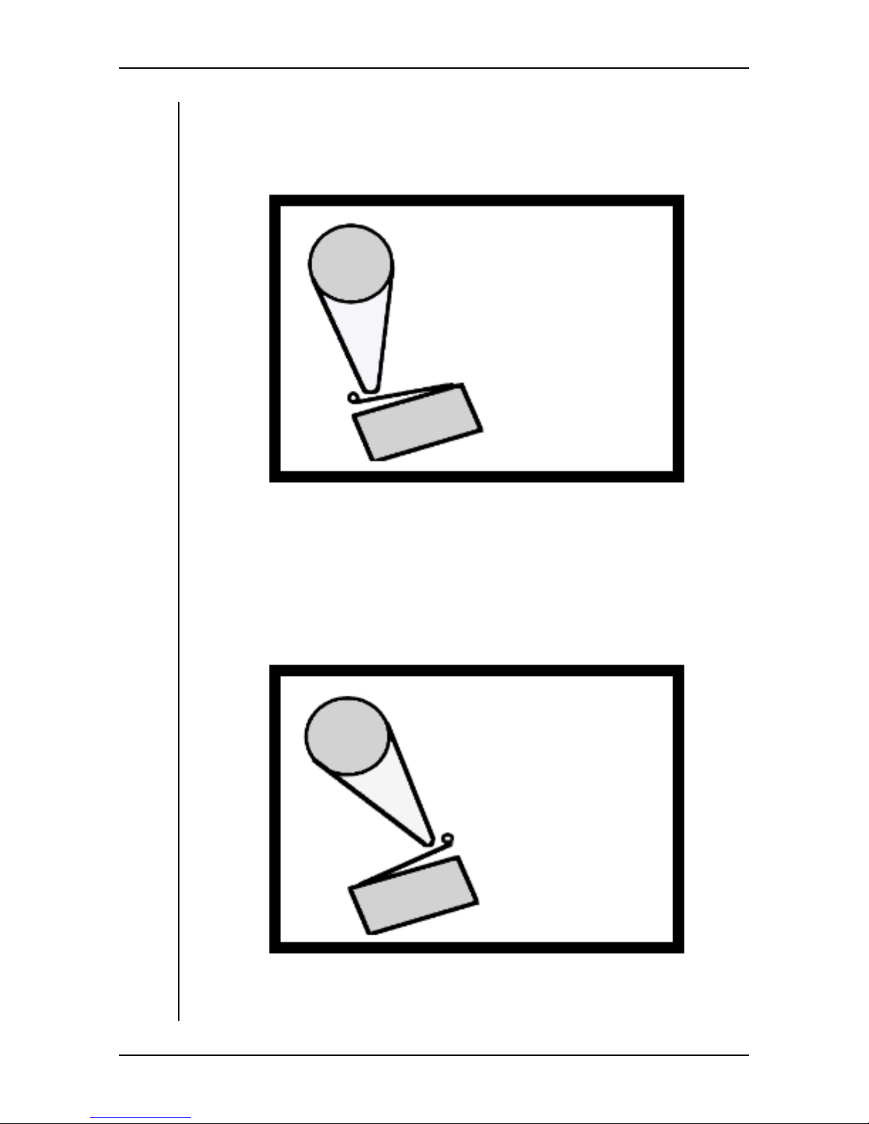
4. Use a 7/64” hex key to loosen the locking screw in the upper cam. Rotate
the cam on the shaft until it is just counter-clockwise of the upper switch
actuator as shown below. Tighten the locking screw.
Position Upper Cam Just CCW
Of Upper Switch Actuator
5. Manually pan the head in a clockwise direction until you reach the desired
limit position (the pan limit cams will rotate counter-clockwise).
6. Use a 7/64” hex key to loosen the locking screw in the lower cam. Rotate
the cam on the shaft until it is just to the clockwise side of the lower switch
actuator as shown below. Tighten the locking screw.
Position Lower Cam Just CW
Of Lower Switch Actuator
7. Replace the tilt motor cover and tighten the 7 screws with a 3/32” hex key.
User Manual 3-15
Page 38
HS-105P Installation
Tilt Limit Switches
References to clockwise (CW) and counterclockwise (CCW) direc tions are the
direction the tilt shutter moves as viewed from the circuit board side - i.e. as
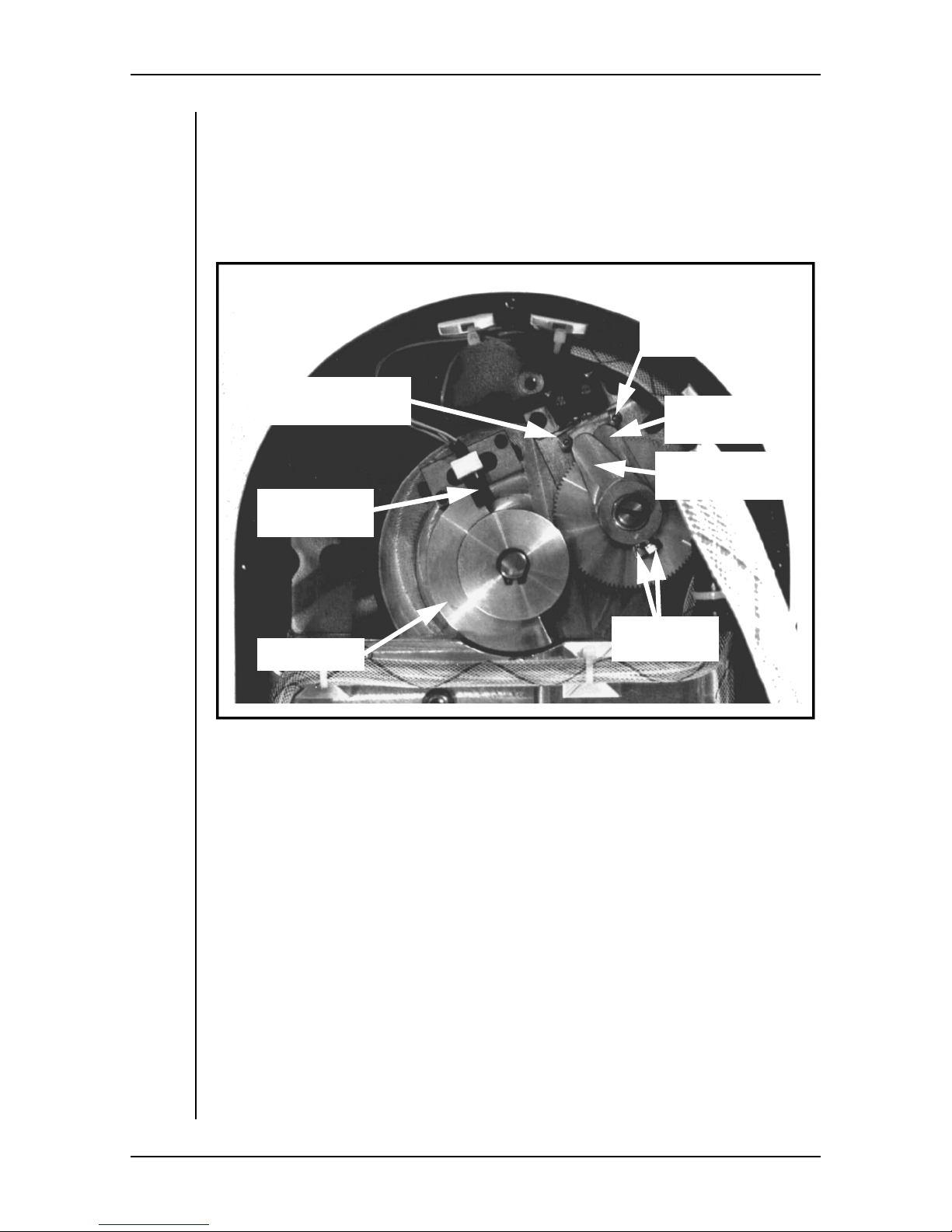
shownin the picture below. The circuit board must be unbolted from the housing
and repositioned to access the tilt limit switches and their respective cams which
are shown below.
CCW (Upper)
Switch Actuator
CW (Lower)
Switch Actuator
Tilt Index
Optosensor
Lower Cam
(CW Pan Limit)
Upper Cam
(CCW Pan Limit)
Cam Lock
Tilt Shutter
Screws
The following procedure assumes that the tilt cradle is still in its index position i.e. horizontal. If the cradle is not horizontal, turn the head power on, allow the
head to index and then turn power off.
To change the tilt limit switch settings:
1. Make sure that the head power switch is Off. Use a 3/32” hex key to
remove the 7 screws in the main cover.
2. Remove the board mounting screw and washer in the upper left corner of
the board. Remove the three hex screws (and washers) that attach the board
(lower right side) to the housing.
3. Carefully lift the board aside to access the limit switches and cams. Be
careful not to strain any cables.
4. Viewing from the circuit board side, manually tilt the cradle so that the tilt
shutter m oves in a counter-clockwise direction - the tilt limit cams will
rotate clockwise - stop when you reach the desired limit position.
3-16 User Manual
Page 39
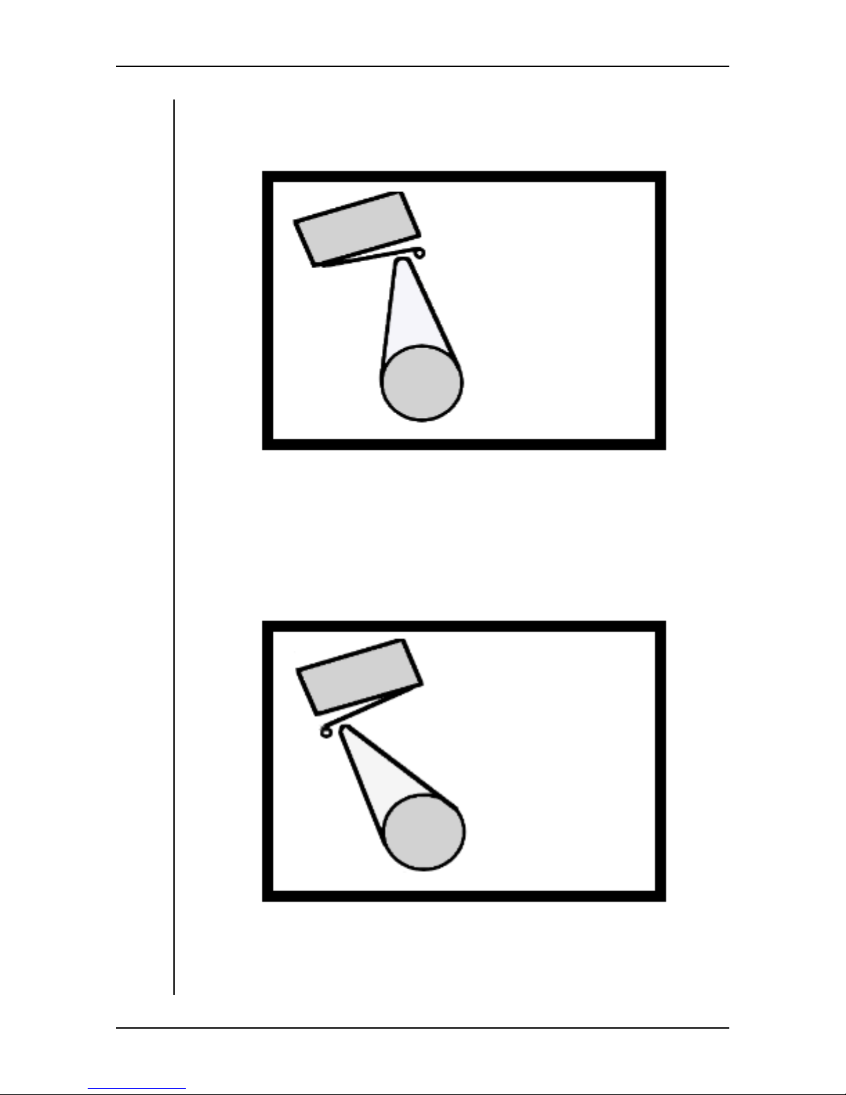
HS-105P Installation
5. Use a 7/64” hex key to loosen the locking screw in the upper cam. Rotate
the cam on the shaft until it is just to the counter-clockwise side of the
upper switch actuator as shown below. Tighten the locking screw.
Position Upper Cam Just CCW
Of Upper Switch Actuator
6. Manually tilt the head to rotate the tilt shutter in a clockwise direction
(viewed from circuit board side) - the tilt limit cams will rotate counterclockwise - stop when you reach the desired limit position.
7. Use a 7/64” hex key to loosen the locking screw in the lower cam. Rotate
the cam on the shaft until it is just to the clockwise side of the lower switch
actuator as shown below. Tighten the locking screw.
Position Lower Cam Just CW
Of Lower Switch Actuator
8. Place the board back into position and replace the mounting screws and
washers. Replace the main cover and use a 3/32” hex key to tighten the 7
screws.
User Manual 3-17
Page 40
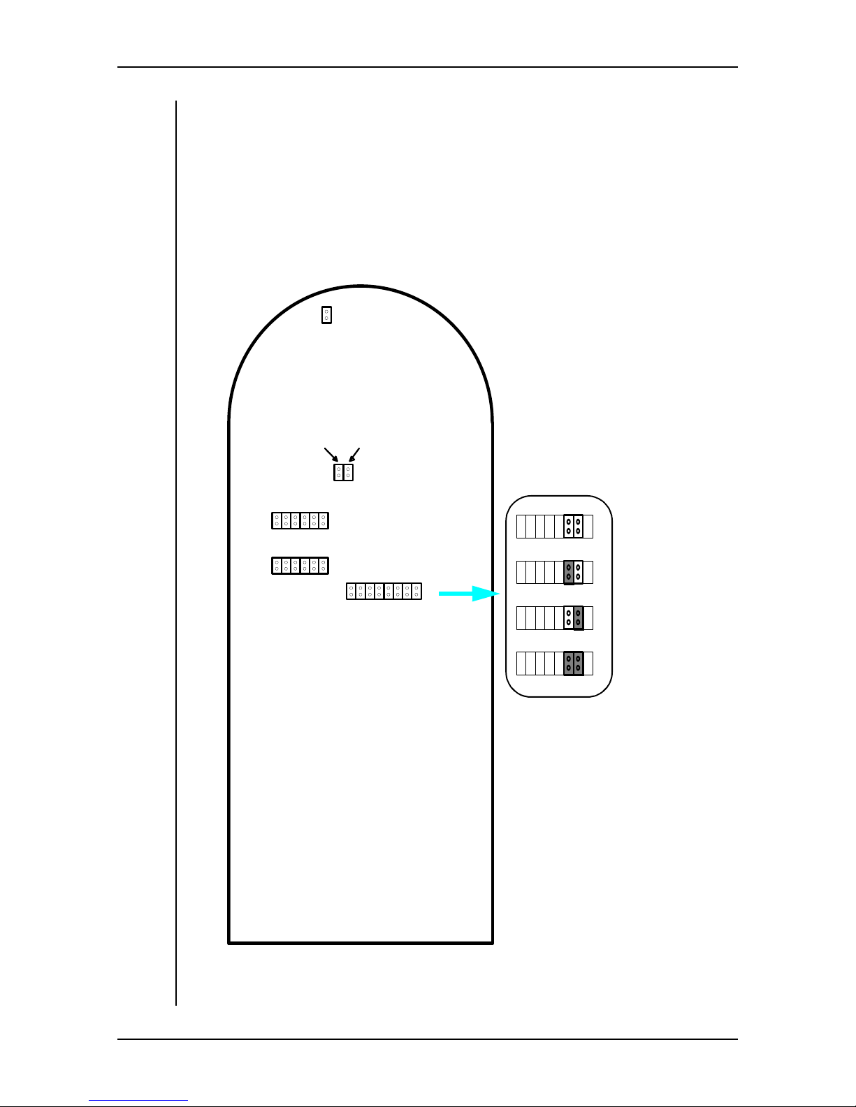
HS-105P Installation
Electrical Clip Limits
Three sets of jumpers (J1, J2 and sections of J3) determine the electrical range
of the pan and tilt servos. Positions 2 and 3 of J3 set the overall range of both
pan and tilt to ±180°, ±90°, ±45° or ±22.5°.
J1 sets the pan clip limit within the overall range and J2 sets the tilt clip within
the overall range. The location of these jumpers is shown below w ith the possible settings for J3 (positions 2 and 3 only) highlighted - shaded = jumper
installed. The other jumpers are described later.
J9
RS422
24009600
Pan Clip
Tilt Clip
J6
1
J1
1
J2
Miscellaneous Functions
1
J3
Range = ±180°
1
J3
1
J3
Range = ±90°
1
J3
Range = ±45°
1
J3
Range = ±22.5°
3-18 User Manual
HS-105P Jumper Locations
Page 41

HS-105P Installation
1. The normal factory default setting is ±90°. Set the jumpers J3-2 and J3-3 as
needed for your installation. Note that J1, J2 and J3 are numbered from
right to left on the board as you look at it.
2. Set the jumpers on J1 for the desired Pan Clip Limit and J2 for the Tilt Clip
Limit. The possible choices are listed in the tables (X = jumper installed)
on the following pages. The normal factory default settings are ±90° for
pan and ±25° for tilt.
User Manual 3-19
Page 42

HS-105P Installation
J1 - Pan Clip Limit
123456
X 174
X 171
X X 169
X 166
X X 163
X X 160
X X X 157
X 155
X X 152
X X 149
X X X 146
X X 143
X X X 140
X X X 137
XXXX 134
X 132
X X 129
X X 126
X X X 123
X X 120
X X X 117
X X X 114
X X X X 111
X X 110
X X X 107
X X X 104
XX XX 101
XXX 98
XXX X 96
XXXX 93
XXXXX 90
X87
XX84
XX81
XXX79
XX 76
Clip Limit
± Degrees
177
3-20 User Manual
Page 43

HS-105P Installation
J1 - Pan Clip Limit
123456
XXX73
XXX70
XXXX67
XX 65
XX X62
XXX 59
XXXX56
Clip Limit
± Degrees
User Manual 3-21
Page 44

HS-105P Installation
J2 - Tilt Clip Limit
123456
X X 143
X X X 141
X X X 138
XXXX 135
X 132
X X 129
X X 126
X X X 124
X X 121
X X X 118
X X X 115
X X X X 112
X X 110
X X X 107
X X X 104
XX XX 101
XXX 98
XXX X 96
XXXX 93
XXXXX 90
X87
XX84
XX81
XXX79
XX 76
XXX73
XXX70
XXXX67
XX 65
XX X62
XXX 59
XXXX56
XXX 53
XXXX51
XXXX 48
XXXXX45
XX 42
Clip Limit
± Degrees
3-22 User Manual
Page 45

HS-105P Installation
J2 - Tilt Clip Limit
123456
XX X 39
XX X 37
XX XX 34
XX X 31
XX X X 28
XX XX 25
XX XXX 22
XXX 20
XXX X 17
XXX X 14
XXX XX 11
XXXX 8
XXXX X 6
XXXXX 3
Clip Limit
± Degrees
User Manual 3-23
Page 46

HS-105P Installation
Other Jumpers
The board in the HS-105P head has a number of other configuration jumpers.
These jumpers are set by Vinten at the factory, or during installation, to match
the requirements of your application. The jumpers (see page 18 for jumper locations) and their functions are as follows.
Miscellaneous Functions - J3
The f unctions of J3 are listed opposite. Positions 1 and 4 are not used. Positions
2 and 3 set the range for pan and tilt in conjunction with the clip limit jumpers to
achieve the desired range. Various damping values (stored in PROM) can be
selected with jumper s in positions 5 and 6. Positions 7 and 8 are used to reverse
the direction of pan and tilt if desired.
J6
Selects the baud rate. Normally set for 9600 baud.
J9
Selects the data communication protocol. Normally set for RS422.
3-24 User Manual
Page 47

HS-105P Installation
J3 - Miscellaneous Functions
12 345 6 7 8
Function
Range Damping
Pan
Direction
Tilt
Direction
Range ±180°
X Range ±90°
X Range ±45°
X X Range ±22.5°
Damping normal
X Damping 2X slower
X Damping 4X slower
X X Damping 8X slower
Pan normal
X Pan reverse
Tilt normal
X Tilt reverse
User Manual 3-25
Page 48

HS-105P Installation
HS-105SA Control Protocol
The SA version uses a custom PROM that provides position feedback to the
controller.
Talking To The HS-105SA
The head expects an 11 byte packet with the following format:
Byte Description
1 8 LSBs of 20 bit pan data
2 Next 8 bits of pan data
3 8 LSBs of 20 bit tilt data
4 Next 8 bits of tilt data
5 4 MSBs of tilt data, 4MSBs of pan data
6 8 LSBs of 16 bit zoom data
7 8 MSBs of zoom data
8 8 LSBs of 16 bit focus data
9 8 MSBs of focus data
10 Reserved - set to 0
11 Checksum
Pan and tilt are unsigned 20 bit integers. Zoom and focus are unsigned 16 bit
integers.
The checksum is the 8 LSBs of the sum of bytes 1 through 10. If the checksum
is incorrect the packet will be ignored.
Communication is RS-422 at 9600 baud, 8 bits, 1 stop, no parity. The head
expects to receive the 11 byte packet in a burst followed by an idle time that is
used to mark the start of the next packet. An idle gap during the packet transmission will be interpreted as a bad packet and ignored.
The head expects the packets to arrive at a rate of 40 per second. This will give
the smoothest performance. If the data rate is slower you will notice some
“notchiness” as the head will try to reach the new position in 25 milliseconds. If
the new position is too far to reach in 25 milliseconds, the head will move at
maximum velocity.
3-26 User Manual
Page 49

HS-105P Installation
Listening To The HS-105SA
The feedback from the head to the controller consists of the actual mechanical
position of the optical encoders on the pan and tilt axes. The data is formatted in
packets with each packet preceded by FF (hex) to indicate the start of a packet.
The format of the data stream is::
Byte Description
1 MSB=0, then 7 MSBs of pan axis data
2 MSB=0, then next 7 bits of pan axis data
3 MSB=0, then 7 MSBs of tilt axis data
4 MSB=0, then next 7 bits of tilt axis data
Feedback starts after the first valid data packet is received.
User Manual 3-27
Page 50

HS-105P Installation
This page left blank intentionally.
3-28 User Manual
Page 51

4 Maintenance And Repair
User Manual 4-1
Page 52

HS-105P Maintenance And Repair
Introduction
In general, AutoCam is a highly reliable and stable product. Many of the
mechanical components are sealed and permanently lubricated. The electronics
are well ventilated and highly rated. The number of connectors is kept to a minimum and the best quality connectors are utilized. All this adds up to a product
that does not require much general routine maintenance.
Service Philosophy
Servicing is supported at three levels by Vinten Inc. after the 12-month warranty
period expires:
• On-site service may be contracted from Vinten Inc. or through the
Sales Representative from which the system was purchased.
• Board-level replacement may be readily accomplished by station
personnel, using stocked or ordered circuit boards.
• Component level replacement is feasible to some extent, by qualified station engineers or technicians, using the material in this
chapter.
Service questions may be directed to factory service specialists at Vinten Inc. in
ValleyCottage,NY,byphoneat1-845-268-0100,ortollfree(intheU.S.A.)at
1-8884VINTEN(1-888-484-6836).YoucanalsofaxVintenat1-845-268-
0113.Anemergencytelephoneserviceisavailable24hoursaday,sevendaysa
weekusingthe1-845-268-0100number.
Avoid Damage From Static Electricity
To avoid damaging your system with static electricity, make sure you are properly grounded before touching any internal components. You can maintain
grounding with a grounded wrist strap, or by periodically touching the bare
metal of the chassis or the housing. Do not shuffle your feet on a carpet or any
other surface that can produce an electric charge.
4-2 User Manual
Page 53
HS-105P Maintenance And Repair
Safety
Service should only be performed by qualified personnel, who
are familiar with the equipment. At some points inside the
power supplies 120 (or 240) volts AC is exposed, with a danger
of electrical shock.
If you must work on a head that is powered up, place a large
WARNING sign at the controller to alert other personnel that
they should not attempt to use the system.
Some tests are performed with the head powered. There is
always a danger that an unexpected motion could cause a
head to strike or pinch you, causing physical injury. Reread
the Safety comments in Chapter 1 of this manual before work-
ing around a powered head.
User Manual 4-3
Page 54

HS-105P Maintenance And Repair
Routine Maintenance
Aside from checking balance and overall operation periodically (once a week
for example), the HS-105P pan/tilt head should require no other routine maintenance in the area of the motor drive and gear train.
Checking Balance
It is recommended that you check the balance at least monthly to ensure proper
operation and to reduce excessive wear on the drive train and potential overheating. An unbalanced load may also affect servo operation and responsiveness.
Unless the mounting screws are loose, the balance should only change if the
camera is moved back and forth for some reason, or if the payload has been
changed.
1. With no power applied to the head, support the camera and head in a horizontal position and feel if the payload is unbalanced (i.e. does it tend to tilt
up or down when you let go).
2. If it is unbalanced, loosen the bolts that hold the camera to the cradle and
carefully push the payload in the desired direction (forwards to counteract
tilt up, or backwards to counteract tilt down). Retighten the mounting bolts
and check again for proper balance. It is best to move the payload in small
increments even though this may require several steps until the balance is
achieved.
3. Once the back and forth balance is achieved, proceed with adjustment of
vertical balance. Tilt the camera approximately 30 degrees upward and
release it. If the camera stays in the same position when released, the payload is properly balanced.
4. However, if the camera continues to move upwards after you let go, the
payload is mounted too high. On the other hand, if the camera moves back
towards the horizontal position when you let go, the payload is mounted
too low. Determine if you need to raise or lower the tilt cradle.
5. Mark the vertical position of the tilt cradle to make sure that you move it in
the desired direction. Have two assistants support the cradle and payload as
you use a 5/32” hex wrench to loosen the two screws that attach the cradle.
6. Raise or lower the cradle as necessary and tighten the screws securely .
NOTE: If you cannot access the cradle screws with the payload mounted, mark
the position of the camera on the tilt cradle so it can be re-installed in the same
position. Remove the camera from the tilt cradle and follow steps 5 and 6. Then
mount the payload back onto the cradle.
7. Repeat step 3 to check the balance. Move the tilt cradle again if necessary
until balance is achieved.
4-4 User Manual
Page 55

HS-105P Maintenance And Repair
Checking Overall Operation
When you check the balance, it is a good idea to check the overall operation of
the head. Use the controller to exercise pan, tilt, zoom and focus through their
ranges. Make sure that the movement of the head is smooth and consistent.
User Manual 4-5
Page 56

HS-105P Maintenance And Repair
Theory Of Operation
Power Supply
The power to the head from the rack mount supply is nominally ±28.5 volts DC,
symmetrical about ground. The circuit board in the head regulates its own operating voltages from the single 30V supply. These on board supplies include a
24V supply for relays, lamps, and solenoids, +15V and -15V for analog circuitry, and +5V for digital circuitry. The +5V and -15V supplies are switching
supplies.
Data Path
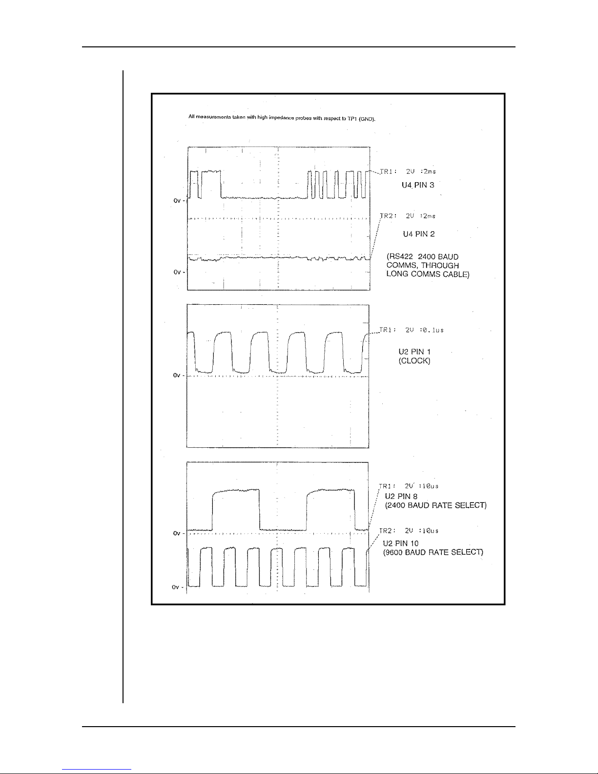
The data bus is a 4-wire uni-directional 9600 baud RS-422 signal between the
AutoCam controller and the head via the power supply. Data is transmitted in
data frames that are sent to and received from the head at 25ms intervals. Within
each frame are command bytes for each servo axis. With RS-422 data, each side
of the data line is the electrical mirror image of each other.Each should look like
a TTL signal. A fault condition is indicated by identical signal phase on both
lines, or one line stuck.
The HS-105P may be used with various Vinten controllers including the HCP8000, LCP-8000P and MultiController II. Depending on the controller used, the
HS-105P baud rate is set with jumpers on the circuit board in the head.
Circuit Theory
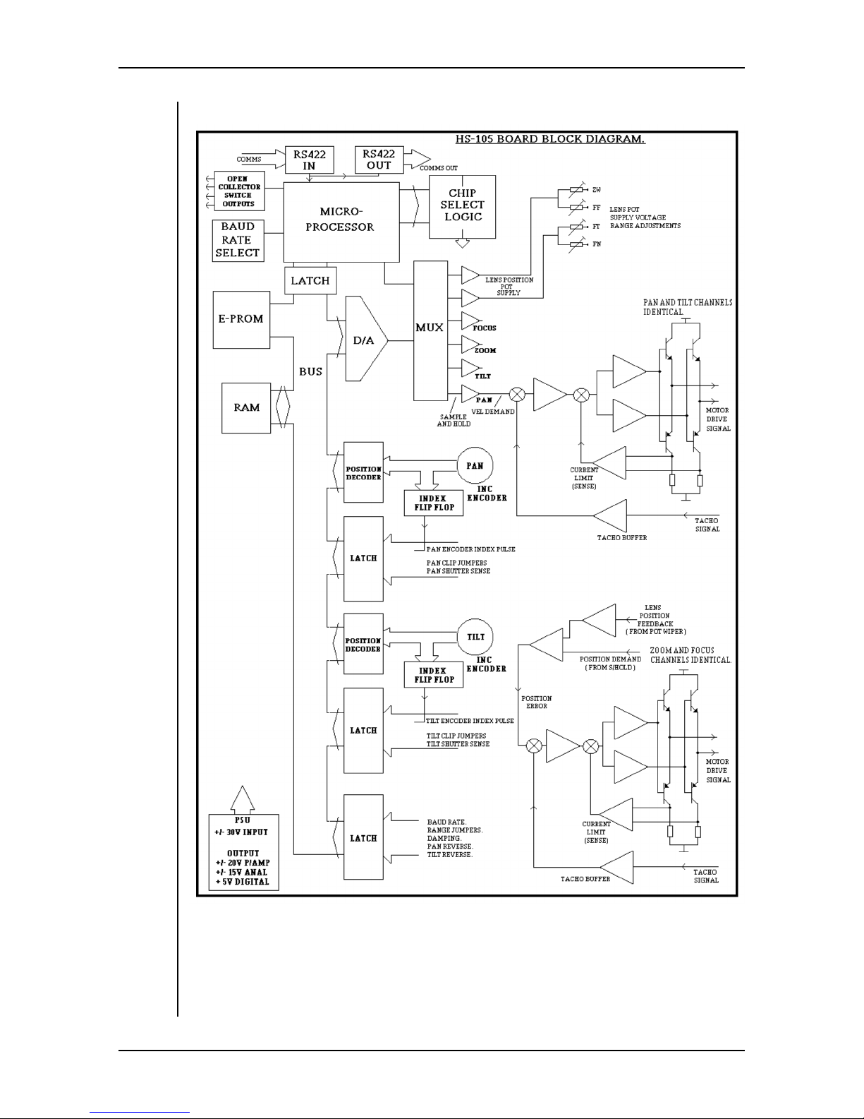
The circuit board in the head controls the four motors for pan, tilt, zoom and
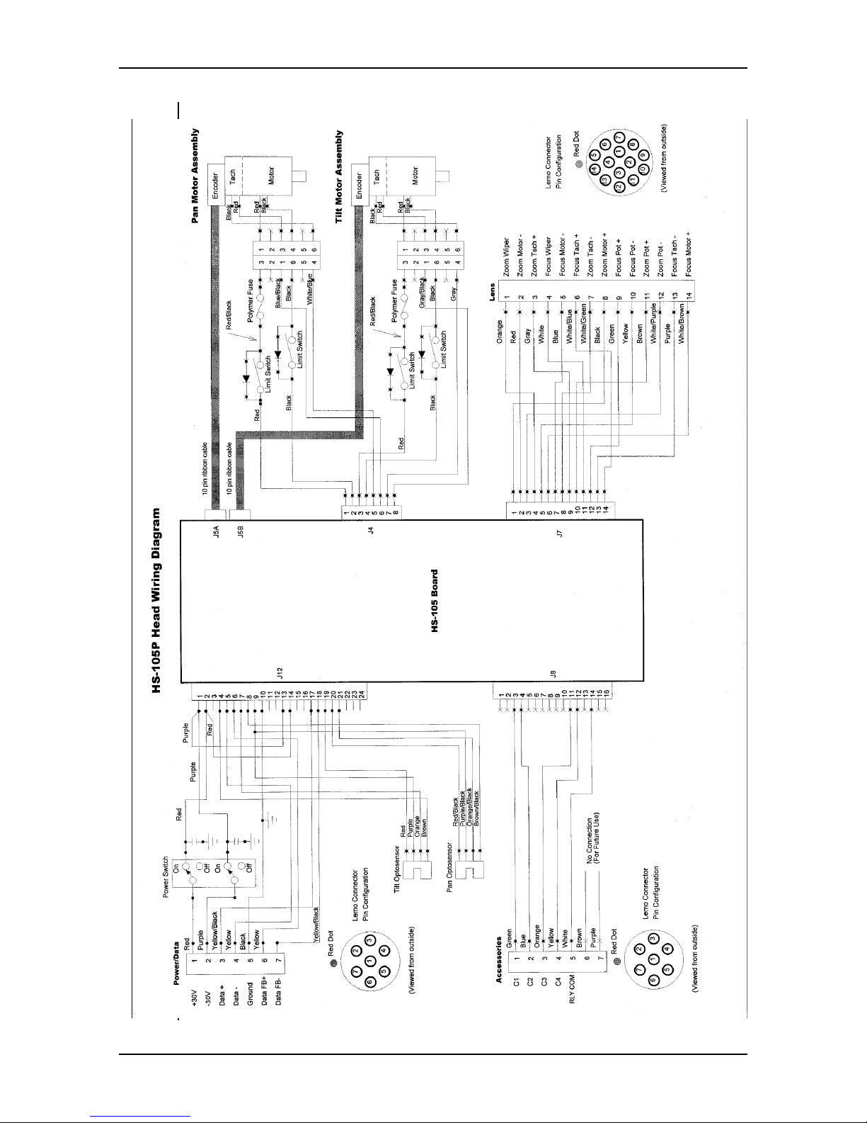
focus. A block diagram of the board is shown opposite and the HS-105P wiring
diagram can be found on the following page.
The board contains a microprocessor, local power supply regulation, servo circuits and data interconnections. The board receives data commands from the
controller at a frame rate of 25ms. This fast frame rate supports the highly
responsive behavior of the Autocam system to joystick commands. However,
this rate is too coarse to feed the motors directly since it would cause rough
movement. Therefore, the 25mS interval is linearly interpolated into shorter segments of a few milliseconds each. After each segment is computed, it is outputted as a position demand signal to the appropriate servo channel. Twoof the four
servo channels are analog channels with a position demand output (for zoom
and focus), and the other two channels are digital channels with a torque
demand output (for pan and tilt).
4-6 User Manual
Page 57
HS-105P Maintenance And Repair
User Manual 4-7
Page 58
HS-105P Maintenance And Repair
4-8 User Manual
Page 59

HS-105P Maintenance And Repair
Analog Servos
The analog position demand servos control zoom and focus of the lens. The 16bit DAC709 D/A converter converts the position demand data to a voltage
between -10V and +10V. This control signal is fed to the zoom/focus driver circuit where the feedback loop is closed with the position feedback signal from
the follow pot on the lens and the tachometer signal from the lens.
Digital Servos
For the digital servo channels, feedback is derived from an incremental encoder
on the servo motor which generates the position follow signal. This follow signal is in the form of quadrature TTL signals which are counted by the on-board
HCTL-2000 ICs. The follow signal is relayed to the microprocessor where it is
compared to the interpolated demand signal. The difference between these two
signals is the position error signal.
The servo tries to produce a motor velocity which is proportional to the position
error. The motor velocity (computed by differentiating the position follow signal, or subtracting subsequent motor positions) is subtracted from the position
error to derive the velocity error. The servo controls the motor current to reduce
the velocity error to zero by feeding the error to the on-board DAC and converting it to a voltage between -10V and +10V to generate the current (or torque)
desired in the motor. The current demand signal leaves the board to feed the
motor amplifier .
Waveforms
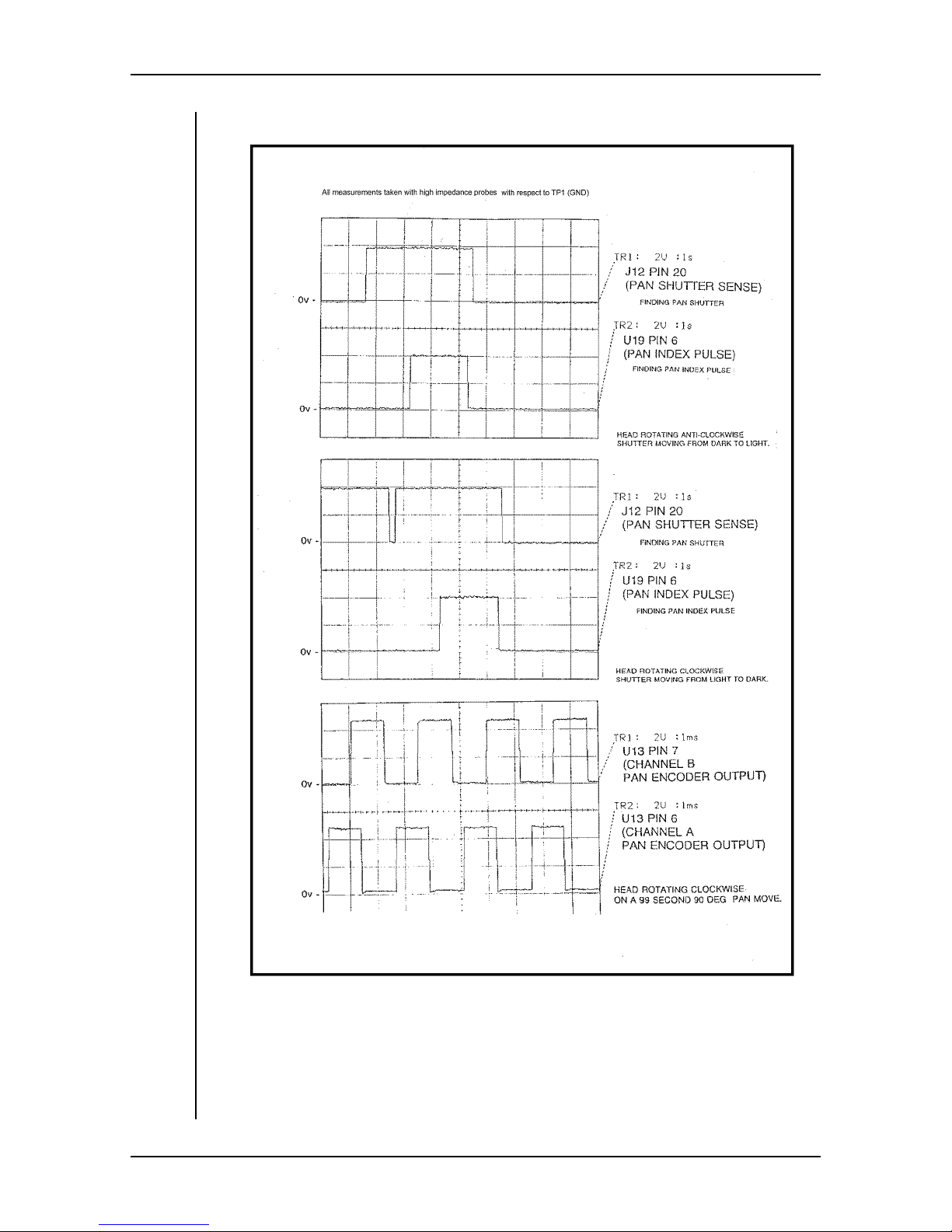
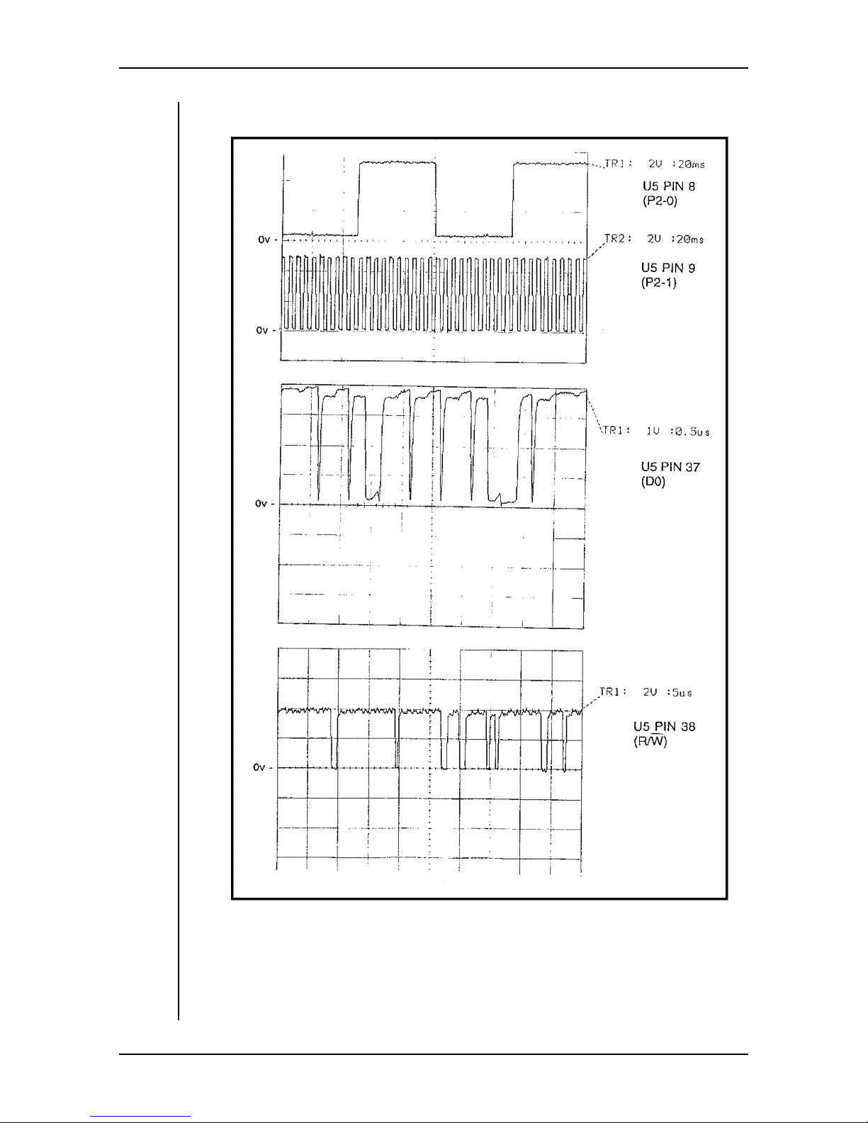
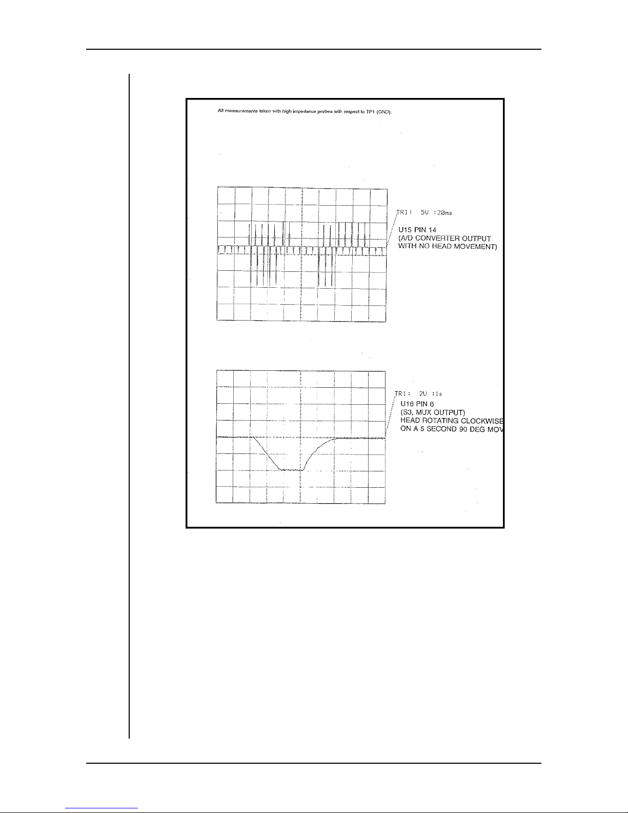
Some typical waveforms can be found later in this manual.
Zoom/Focus Servo
The HS-105P board contains the motor drivers and servo loop circuitry for the
zoom and focus servos (except when native lens control is employed). The
inputs to the servos are position-demand voltages and feedback pot signals. The
output is the current signal to the lens. The zoom and focus sections of the board
are identical.
The board compares the voltage from the lens follow pots to the demand signals
to determine the error signal. The board then tries to produce a motor velocity
proportional to this error. The error signal is compared to the velocity signal
from the tachometer. The error is then amplified, shifted in voltage to be symmetrical about a level that is half of the supply voltage, and fed to the TIP102/
107 emitter-follower current amplifiers, which in turn drive the zoom and focus
motors. A delay circuit (including relays RY1and RY2) slows the turn-on of this
servo to prevent turn-on transients which might slam the lens into its end stops.
During installation, the four calibration pots are adjusted so that the full range of
demand voltage from the controller causes exact end-to-end motion of the lens.
The resistor carrier R84 in the lower left corner of the board carries 10 fixed
resistors (two of the “resistors” are generally 0 ohm links - R84-3 and R84-10)
User Manual 4-9
Page 60

HS-105P Maintenance And Repair
that set the speed and accuracy characteristics of the lens servo. Several carriers
have been optimized by Vinten Inc. for popular lens types, and it is important
that you have the correct one installed for your lens. Four of the resistors (and a
0 ohm link) are in the focus servo and four (and a 0 ohm link) in the zoom servo.
Typically, the two servos have the same resistor values.
Two resistors in each servo (R84-1, R84-2, R84-7, R84-9) set the maximum current to the lens motors to provide adequate power for fast response, without supplying excess current that could shorten motor life. Vinten Inc. selects these
resistor values to match the lens motor specifications.
The third resistor in each servo (R84-5, R84-8) sets the tachometer gain. The
value affects the traverse speed of the servo, but is primarily used to prevent
overshoot. The value is chosen by providing a step voltage demand input to the
servo. When properly selected, the servo should move responsively, without
overshootingthe end position. This will prevent the lens from slamming into the
end stops and causing excessive wear or damage.
The fourth resistor in each servo (R84-4, R84-6) sets the loop gain or stiffness.
A stiffer servo has more gain and produces greater repeatability. However, if the
gain is too high, the servo will start to buzz or oscillate or overshoot. Y ou want
to set the gain as high as possible, but short of the point of oscillation. A conservative procedure would be to take it up to the point of buzzing, and then drop
back to a resistor of half that value.
Head Indexing Procedure
At power up, the HS-105 has to reset the pan and tilt axes to known mechanical
positions. This is achieved by finding the edge of the pan shutter (coarse positioning) and then finding the pan index pulse (fine positioning). The same procedure is then used for the tilt axis. After the indexing is finished, the head moves
to the position requested by the controller. If a controller is not connected, there
should be no movement after the indexing is complete.
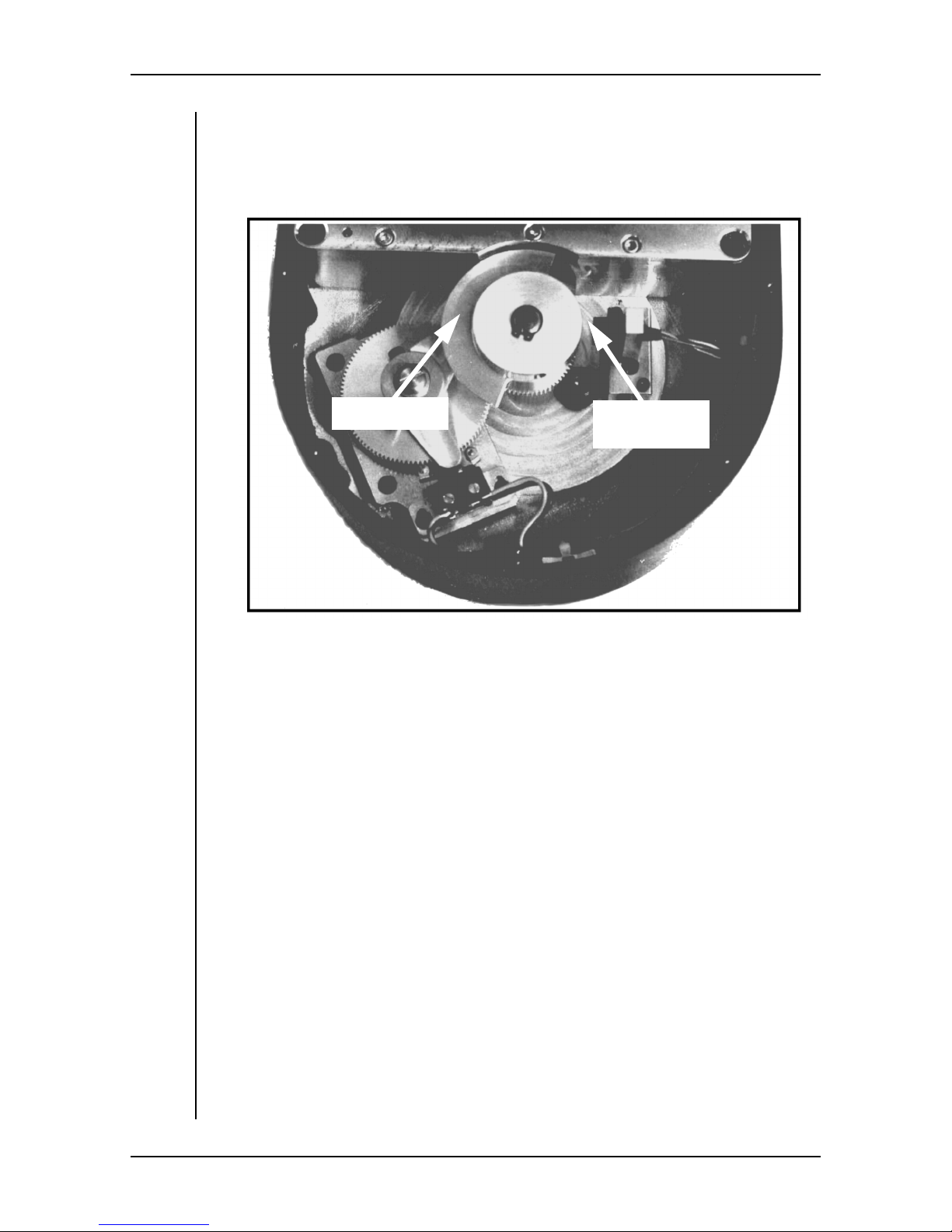
As shown below, the pan shutter is a 180° metal vane which breaks the light
beam of an optosensor. The index position is at one end of the shutter - where
the optosensor transitions from open to blocked. The index pulse is a marker
within the incremental opto-encoder which is part of the motor assembly. The
tilt axis is identical. The sequence of events is:
1. At power up, the head pans slowly in search of the pan shutter edge. When
the edge is found, the head pans (clockwise as viewed from above) more
slowly for a few degrees to find the index pulse from the motor encoder.
During the search for the index pulse, the LED DS1 will be on. The LED
goes out when the index pulse is found. The pan position is now reset.
2. The tilt axis moves slowly in search of the tilt shutter edge. During this
search, the pan axis mimics the tilt movement.When the tilt shutter edge is
found, the head tilts (clockwise as viewed from the PCB side) more slowly
for a few degrees to find the index pulse from the tilt motor encoder. Tilt is
now reset.
4-10 User Manual
Page 61
HS-105P Maintenance And Repair
3. The head moves to the current pan and tilt positions requested from the
control panel (if one is connected and active) and is ready to operate.
After the optosensor finds the shutter edge, the motor shaft will turn a maximum
of 180° to find the index mark.
Pan Shutter
Pan Index
Optosensor
User Manual 4-11
Page 62
HS-105P Maintenance And Repair
Motor Drive Fuses
To protect against over current conditions, a polymer “fuse” is inserted in series
with the positive drive wire to the pan and tilt motors - see the wiring diagram on
page 8. In normal operation, with a short term over current, the resistance of the
“fuse” increases to reduce the current through the motor. When the over current
is removed, the “fuse” return to its normal low resistance.
However,if a long term over current exists (or repeated over current conditions),
the polymer “fuse” may eventually fail. This is more likely to occur in the tilt
drive where an unbalanced load will cause the drive current to be higher than
normal. The pan drive circuit is identical, but rarely suffers a fuse failure.
Tilt Fuse Failure
The first indication of a tilt fuse failure will occur during indexing at power up.
If the tilt fuse is open circuit, the pan axis will find its shutter and index pulse as
normal. Then, when the tilt axis is supposed to search for its shutter, there will
be no tilt m otion due to the blown fuse. However, the pan axis will be still be
moving as it mimics the demand for tilt search. The pan axis will move slowlyat
first, then more slowly for a few degrees, then starts to drift until it reaches the
end stop microswitch.
You can confirm that the problem is with the tilt axis by pushing gently on the
tilt cradle at power up to see if the servo is locked. If the cradle moves easily
when you push it, the tilt servo is not operating to hold the cradle in position. A
possible c ause is a tilt fuse failure.
Tilt Fuse Replacement
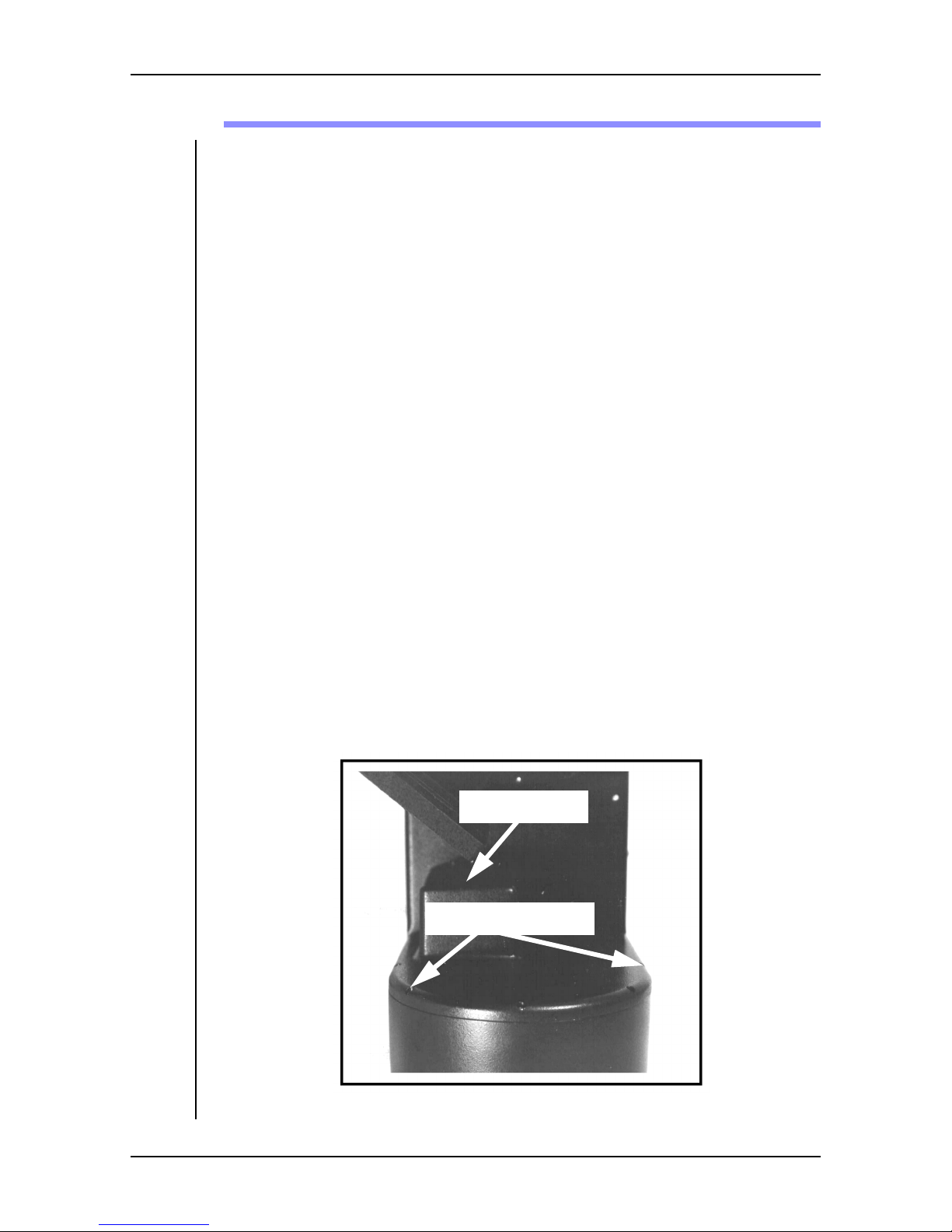
1. Use a 3/32” hex key to remove the 7 screws from the tilt motor cover.
Motor Cover
Remove 7 Screws
4-12 User Manual
Page 63
HS-105P Maintenance And Repair
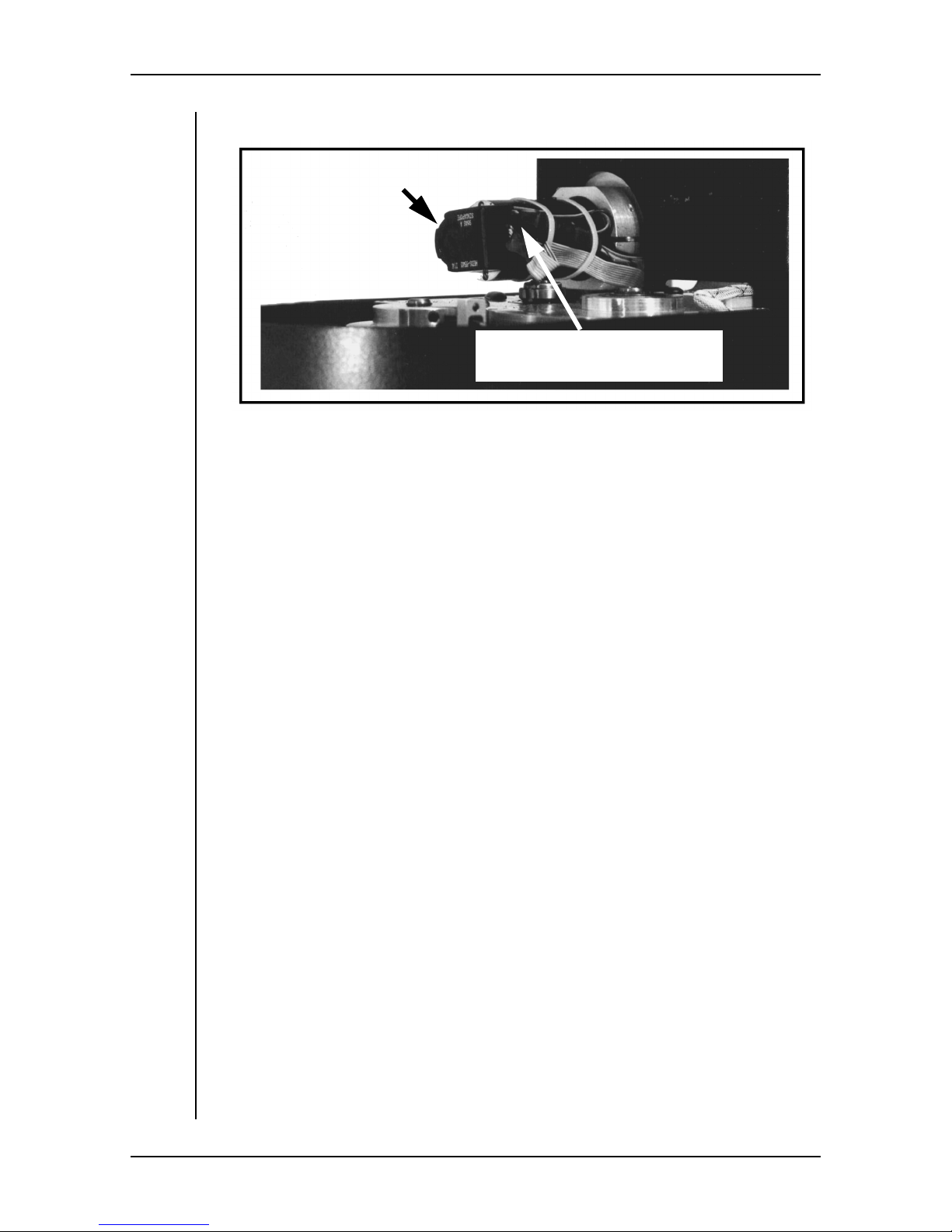
2. Note the positions of the cable ties and carefully cut and remove them.
Tilt Motor/Tacho/
Encoder Assembly
Heat Shrink Covered Fuse
(cable tied to motor)
3. Carefully cut the heat shrink tubing from the in-line fuse, taking care not to
cut any wires. Unplug the two halves of the in-line connector.
4. Unsolder the polymer fuse from the red wire and from the pin of the in-line
connector.
5. Slide new heat shrink tubing onto the motor supply wires.
6. Solder the newfuse to the pin of the in-line connector and to the red “motor
supply” wire.
7. Plug the two halves of the in-line connector together, slide the heat shrink
tubing over the fuse and in-line connector.
8. Carefully apply just enough heat to shrink the tubing, but not enough to
damage the fuse.
9. Cable tie the wiring back into position, making sure that the wires and the
cable ties do not rub on the pan shaft lock nut.
10. Reattach the motor cover and tighten the screws securely with a 3/32” hex
key .
User Manual 4-13
Page 64

HS-105P Maintenance And Repair
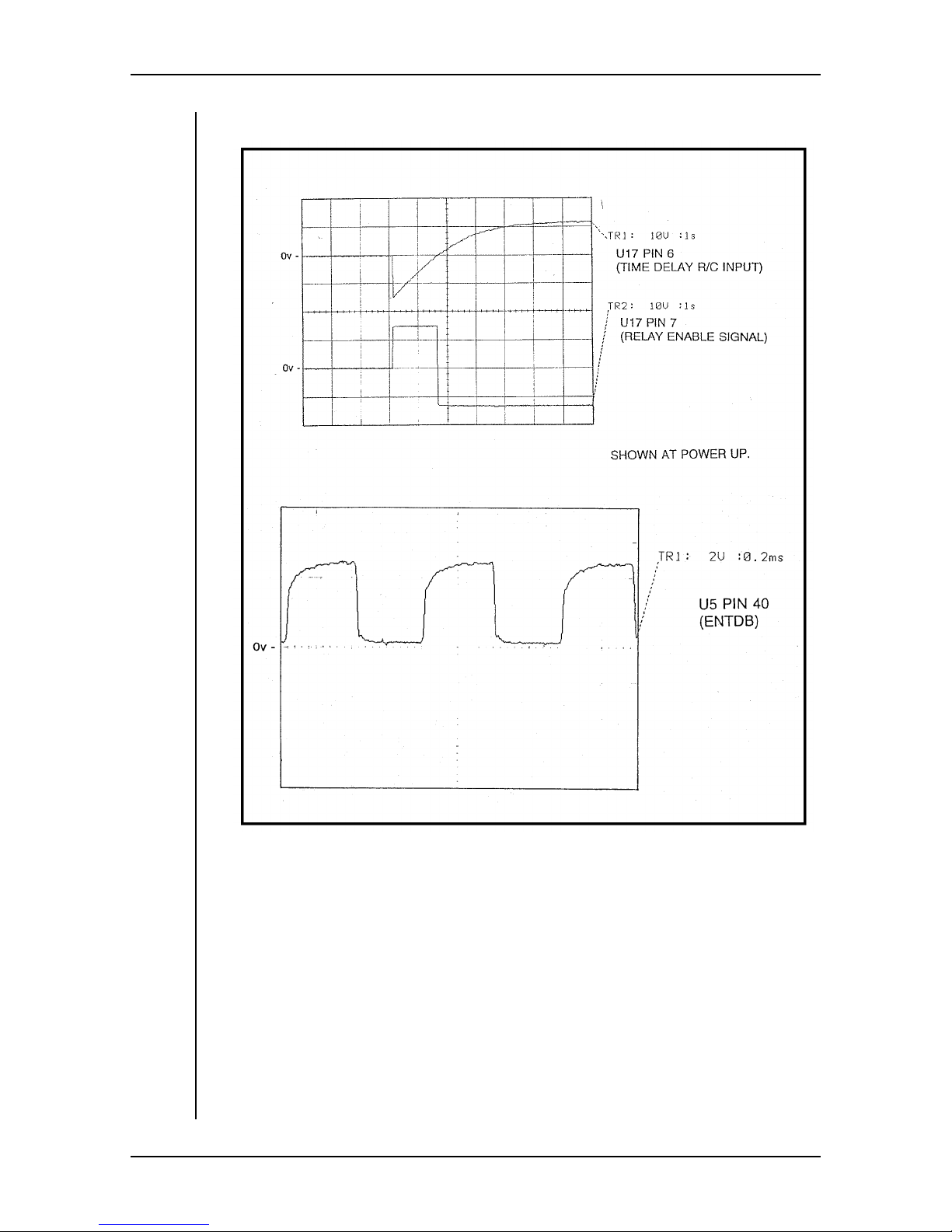
Waveform Diagrams
The waveforms on the followingpages may be helpful when troubleshooting the
HS-105P.
4-14 User Manual
Page 65
HS-105P Maintenance And Repair
User Manual 4-15
Page 66
HS-105P Maintenance And Repair
4-16 User Manual
Page 67
HS-105P Maintenance And Repair
User Manual 4-17
Page 68
HS-105P Maintenance And Repair
4-18 User Manual
Page 69
HS-105P Maintenance And Repair
User Manual 4-19
Page 70

HS-105P Maintenance And Repair
This page left blank intentionally.
4-20 User Manual
Page 71

HS-105P Index
A
ACP System 1–10
Analog Servos 4–9
Applications 1–10
Focus Servo 4–9
Follow Pot Adjustment 3–7
Fuse Failure 4–12
Fuse Replacement 4–12
Fuses, Motor Drive 4–12
B
Backlash, Minimizing 3–7
Balance, Checking 4–4
Balancing The Payload 3–4
Baud Rate Jumper 3–24
Block Diagram 4–7
C
Calibration, Zoom and Focus 3–12
Checking Balance 4–4
Checking Overall Operation 4–5
Circuit Theory 4–6
Clip Limit Jumpers 3–18
Configuration 3–12
Configuration Jumpers 3–24
Control Protocol, HS-105SA 3–26, 3–27
Critical Data For HS-105 iii
Customer Responsibility 1–2
H
HCP System 1–10
Head Indexing 4–10
HS-105PE 1–9
HS-105SA 1–8
I
Indexing At Power Up 4–10
Installation
Balancing The Payload
Electrical 3–10
Lens Drive 3–6
Mounting The Head 3–4
Mounting The Payload 3–4
Installation, Mechanical 3–4
Installation, Tools Needed 3–2
Interconnection, Electrical 3–10
3–4
D
Damping Jumper 3–24
Data Path Theory 4–6
Digital Servos 4–9
E
Electrical Clip Limits 3–18
Electrical Installation 3–10
Electrical Interconnection 3–10
F
Features 1–6
Focus Calibration 3–12
J
Jumper, Baud Rate 3–24
Jumper, Pan/Tilt Direction 3–24
Jumper. Damping 3–24
Jumpers, Configuration 3–24
L
LCP System 1–10
Lens Drive Installation 3–6
Lens Drive Setup 3–6
Lens Drive, Follow Pot Adjustment 3–7
Lens Drive, Minimizing Backlash 3–7
Limit Switches, Pan 3–14
Limit Switches, Tilt 3–16
Limits, Pan And Tilt 3–14
Listening To The HS-105SA 3–27
I
Page 72

HS-105P Index
M
Manual Outline 1–5
Mechanical Installation 3–4
Motor Drive Fuses 4–12
Mounting The Pan & Tilt Head 3–4
Mounting The Payload 3–4
MultiController II System 1–10
O
Operating Footprint 1–3
Operation 2–1
P
Pan Limit Switches 3–14
Pan Limits 3–14
Pan/Tilt Direction Jumper 3–24
Pinch Points 1–4
Power Supply Theroy 4–6
Power Switch 1–4
Tilt Fuse Replacement 4–12
Tilt Limit Switches 3–16
Tilt Limits 3–14
Tools You Will Need 3–2
Typical Applications 1–10
W
Warning
Customer Responsibility
Operating Footprint 1–3
Pinch Points 1–4
Power Switch 1–4
Safe Operating Zone 1–3
Safe Working Environment 1–2
Sharp Edges 1–4
Static Electricity 4–2
Unexpected Motion 1–3
Warning Labels ii
Warning Signs 1–3
Warnings 1–2
Warranty v
Waveform Diagrams 4–14
Wiring Diagram 4–8
1–2
S
Safe Operating Zone 1–3
Safe Working Environment 1–2
Safety 1–2
Service Philosophy 4–2
Servo, Zoom/Focus 4–9
Servos, Analog 4–9
Servos, Digital 4–9
Setup, Lens Drive 3–6
Sharp Edges 1–4
Signs, Warning 1–3
Specifications 1–7
Static Electricity 4–2
Support, Technical iv
T
Talking To The HS-105SA 3–26
Technical Support iv
Tilt Fuse Failure 4–12
Z
Zoom Calibration 3–12
Zoom Servo 4–9
II
 Loading...