

Vinten FH-145, FHR-145 User Manual
www.vinten.com
Part Nos. V4101-0001
FH-145, FHR-145 Pan and Tilt Head
FH-145
FHR-145
Pan and Tilt Head
V4102-0001

Original Instructions: English
Copyright © 2016
All rights reserved throughout the world. No part of this document may be
stored in a retrieval system, transmitted, copied or reproduced in any way,
including, but not limited to, photocopy, photograph, magnetic or other record
without the prior agreement and permission in writing of the Vitec Group plc.
Disclaimer
The information contained in this manual is believed to be correct at the time
of printing. Vitec Videocom Ltd. reserves the right to make changes to the
information or specifications without obligation to notify any person of such
revision or changes. Changes will be incorporated in new versions of the
publication.
We are making every effort to ensure that our manuals are updated on a
regular basis to reflect changes to product specifications and features. Should
this manual not contain information on the core functionality of your product,
please let us know. You may be able to access the latest revision of this
manual from our website.
Ltd. reserves the right to make changes to product design and
functionality without notification.
Trademarks
All product trademarks and registered trademarks are the property of the
Vitec Group plc.
All other trademarks and registered trademarks are the property of their
respective companies.
Published by:
Vitec Videocom
Supports Technical Publications Dept.
E-mail: technical.publications@vitecgroup.com
Vitec Videocom

1
FHR-35 Robotic Pan and Tilt Head
Components and Connections . . . . . . . . . . . . . . . . . . . . . . . . . . . . . . . . . . . . . . . . . . . . . . . . . . . . . . 4
Installation . . . . . . . . . . . . . . . . . . . . . . . . . . . . . . . . . . . . . . . . . . . . . . . . . . . . . . . . . . . . . . . . . . . . . . 5
Box Contents and Tools Required . . . . . . . . . . . . . . . . . . . . . . . . . . . . . . . . . . . . . . . . . . . . . . . . . . 5
Mounting Supports and Adaptors . . . . . . . . . . . . . . . . . . . . . . . . . . . . . . . . . . . . . . . . . . . . . . . . . . 6
Cable Management Brackets . . . . . . . . . . . . . . . . . . . . . . . . . . . . . . . . . . . . . . . . . . . . . . . . . . . . . 7
Removing the Camera Cradle . . . . . . . . . . . . . . . . . . . . . . . . . . . . . . . . . . . . . . . . . . . . . . . . . . . . . 7
Setting the Pan and Tilt Mechanical Hard Stops . . . . . . . . . . . . . . . . . . . . . . . . . . . . . . . . . . . . . . . 8
. . . . . . . . . . . . . . . . . . . . . . . . . . . . . . . . . . . . . . . . . . . . . . 9
. . . . . . . . . . . . . . . . . . . . . . . . . . . . . . . . . . . . . . . . . . . . 10
Ceiling Mounting . . . . . . . . . . . . . . . . . . . . . . . . . . . . . . . . . . . . . . . . . . . . . . . . . . . . . . . . . . . . . . . 11
Wall Mounting. . . . . . . . . . . . . . . . . . . . . . . . . . . . . . . . . . . . . . . . . . . . . . . . . . . . . . . . . . . . . . . . . 12
Pozi Loc Tripod Mounting Options . . . . . . . . . . . . . . . . . . . . . . . . . . . . . . . . . . . . . . . . . . . . . . . . . 13
. . . . . . . . . . . . . . . . . . . . . . . . . . . . . . . . . . . . . . . . . . . . . . . . . . . . . . . . . . . . . . . . . 21
Maintenance . . . . . . . . . . . . . . . . . . . . . . . . . . . . . . . . . . . . . . . . . . . . . . . . . . . . . . . . . . . . . . . . . . . . 17
Troubleshooting . . . . . . . . . . . . . . . . . . . . . . . . . . . . . . . . . . . . . . . . . . . . . . . . . . . . . . . . . . . . . . . . . 23
General Notices. . . . . . . . . . . . . . . . . . . . . . . . . . . . . . . . . . . . . . . . . . . . . . . . . . . . . . . . . . . . . . . . . . 24
Safety and Warnings . . . . . . . . . . . . . . . . . . . . . . . . . . . . . . . . . . . . . . . . . . . . . . . . . . . . . . . . . . . . . . 2
Setting the Tilt Mechanical Hard Stops
Setting the Pan Mechanical Hard Stops
HD Tripod Mounting Options . . . . . . . . . . . . . . . . . . . . . . . . . . . . . . . . . . . . . . . . . . . . . . . . . . . . . 15
Locking/Unlocking the Camera Cradle . . . . . . . . . . . . . . . . . . . . . . . . . . . . . . . . . . . . . . . . . . . . . 17
Mounting the Camera . . . . . . . . . . . . . . . . . . . . . . . . . . . . . . . . . . . . . . . . . . . . . . . . . . . . . . . . . . 17
Balancing the Head . . . . . . . . . . . . . . . . . . . . . . . . . . . . . . . . . . . . . . . . . . . . . . . . . . . . . . . . . . . . 18
Electrical Connections . . . . . . . . . . . . . . . . . . . . . . . . . . . . . . . . . . . . . . . . . . . . . . . . . . . . . . . . . . 20
Cable Management . . . . . . . . . . . . . . . . . . . . . . . . . . . . . . . . . . . . . . . . . . . . . . . . . . . . . . . . . . . . 21
Powering Up
Operation . . . . . . . . . . . . . . . . . . . . . . . . . . . . . . . . . . . . . . . . . . . . . . . . . . . . . . . . . . . . . . . . . . . . . . 22
Contents
FHR-35 Robotic Pan and Tilt Head
Safety and Warnings
Follow all warnings and instructions marked on the product
and in this manual. Safety warnings are included in this
manual. These safety instructions must be followed to avoid
possible personal injury and damage to the product.
WARNING! Do not install this product onto a bracket,
support or other equipment that is not designed to support
the weight of the product and its payload. All supports must
comply with local government regulations.
WARNING! The fitting of non-approved parts and
accessories, or the carrying out of non-approved alterations
or servicing can be dangerous and could affect the safety of
the product. It may also invalidate the terms and conditions
of the product warranty.
WARNING! This product must be connected to a power
supply of the same voltage (V) and current (A) as indicated
on the product and described in the Technical
Specifications section of this manual. To reduce the risk of
electric shock, do not remove the covers. No userservicable parts inside. Refer all servicing to qualified
service personnel.
WARNING! This product is Class 1 equipment. For safe
operation this equipment must be connected to a power
supply that has a protective earth connection (US: ground).
CAUTION! FHR-145 only – This product is designed for
robotic use only and is operated remotely. Do not attempt to
operate this product manually.
CAUTION! Slots and openings are intended for ventilation
purposes to ensure reliable operation of the product and
protect it from overheating. Do not block or cover any slots
and openings.
CAUTION! Do not use solvent or oil-based cleaners,
abrasives or wire brushes to remove accumulations of dirt
as these damage the protective surfaces. To clean
mechanical surfaces, use only detergent-based cleaners.
CAUTION! Do not use oil or grease on any exposed part
of the product. This is unnecessary and traps dirt which
acts as an abrasive.
WARNING!
Risk of personal injury. All personnel must be
fully trained and adhere to correct manual handling
techniques. It is the responsibility of the individual and the
local organisation to enforce safe working practices at all
times.
WARNING! Risk of personal injury or injury to others. All
personnel must be fully trained and adhere to local health
and safety laws and guidelines. It is the responsibility of the
local organisation to enforce safe working practices at all
times.
For your personal safety, read these instructions. Do not
operate the product, if you do not understand how to use it
safely. Save these instructions for future reference.
Electrical Connections
Basic Electrical Insulation (Class 1 equipment)
Ventilation and Overheating
Cleaning and Maintenance
WARNING! When wiring directly to a studio power supply,
the product must be connected to a switched 3A fused
outlet.
2
FHR-35 Pan and Tilt HeadRobotic
3
FHR-35 Robotic Pan and Tilt Head
Safety and Warnings
Warning Signs
Warning signs should be displayed prominently in the workplace
alerting personnel that robotic equipment is in use and may move
suddenly and without warning.
If personnel are working on robotic or associated equipment, ensure
a warning sign is placed at the controller (control panel) to alert
operators that work is being carried out.
Safety Notes for Operators
Operators must familiarise themselves with the working footprint of
the robotic head, including all associated equipment (lens, zoom and
focus controls, viewfinder, prompter, etc.) to prevent inadvertent
collisions or injury to personnel.
If personnel are too close to a head or pedestal that is about to
move, the operator should prevent the motion from starting or stop
the motion if it has started.
We strongly recommend that the operator verifies visually that the
active area is clear of hazards and personnel, both before and during
remote operation.
Intended Use
This product is designed for use within television studios to support
and balance a camera together with ancillary equipment weighing up
to 65 kg (145 lb). Camera operators can remotely control the head
pan and tilt axes, and the lens zoom and focus using Vinten control
systems.
Safe Working Environment
In normal operation, remote-controlled equipment can move
suddenly and without warning. Since audible warnings are not
suitable for use within the studio environment, it is recommended
that only trained personnel be allowed to work in the active areas,
where remote-controlled heads and pedestals are located.
Personnel must be made aware of the potential hazards of working
in a robotic environment. To avoid personal injury, personnel should
always exercise caution when working in the vicinity of robotic
equipment. The forces are sufficient to cause personal injury or injury
to others, and therefore caution is essential.
Safe Operating Zone
The safe operating zone for personnel is a minimum of 1 m (3 ft)
outside of the footprint of the pan and tilt head.
In most installations, the teleprompter (if installed) is mounted onto
the head and protrudes the furthest beyond the base of the head.
The footprint must take into account the overhang of the
teleprompter or other payload equipment as the head moves about
the pan axis.
CAUTION! Risk of damage to equipment. Do not lift or carry
the head by the back cover.
WARNING! The tilt lock MUST be engaged whenever the
head is lifted or transported and before installing or adjusting
the camera or payload.
4
FHR-35 Robotic Pan and Tilt Head
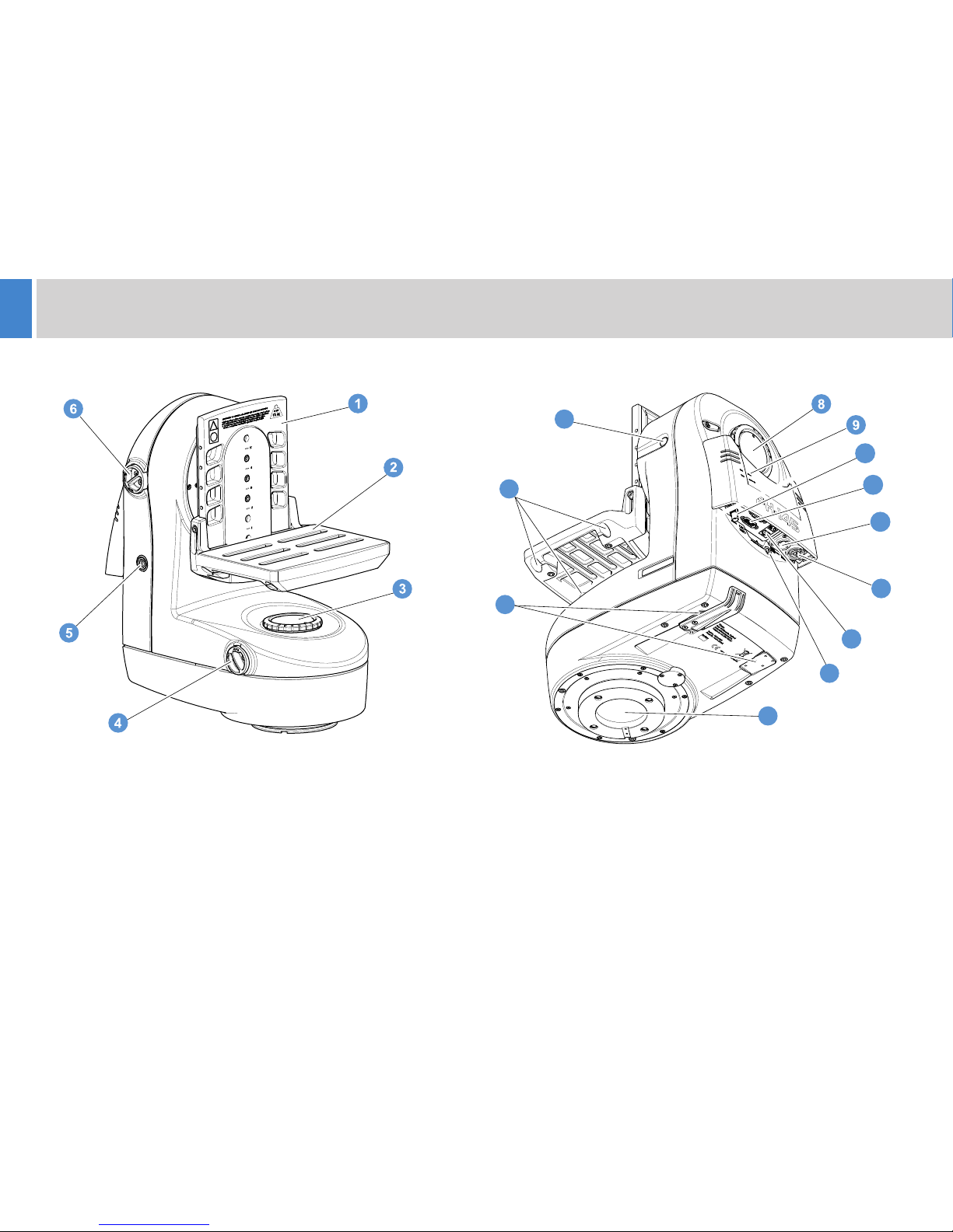
Components and Connections
Front View Rear View
11 . . . . . . . . . . . . . . . . . . . . . Serial connectors (Lens, GP I/O)
12. . . . . . . . . . . . . . . . . . . . . . . . . . . . . . . . . . . . . . . . Power IN
13 . . . . . . . . . . . . . . . . . . . . . . . . . . . . Power OUT (not in use)
14. . . . . . . . . . . . . . . . . . . . . . . . . . . . . . . . . . . . . Ethernet port
15 . . . . . . . . . . . . . . . . . . . . . . . . . . . . . . . . Fuse compartment
18 . . . . . . . . . . . . . . . . . Rod openings (for pan bar assembly)
19 . . . . . . . . . . . . . . . . . . . . . . . . . . . . . Tilt lock release button
16 . . . . . . . . . . Base with Quickfix groove, Mitchell key mount
17 . . . . . . . . . . Cable management bracket attachment points
1
7 . . . . . . . . . . . . . . . . . . . . . . . . . . . . . . . . . . . . Tilt lock button
8. . . . . . . . . . . . . . . . . . . . . . . . . . . . . . . . . . . . . . Tilt drag dial
9 . . . . . . . . . . . . . . . . . . . . . . . . Genlock/Data indicator lights
10 . . . . . . . . . . . . . . . . . BNC connector (for VR functionality)
. . . . . . . . . . . . . . . . . . . . . . . . . . . Camera cradle backplate
2. . . . . . . . . . . . . . . . . . . . . . . . . . . . . . . . . . . . Mounting plate
3 . . . . . . . . . . . . . . . . . . . . . . . . . . . . . . . . . . . . . Pan drag dial
4 . . . . . . . . AUTO/MANUAL pan control switch (FH-145 only)
5 . . . . . . . . . . . . . . . . . . . . . . . . . . . . . Power ON/OFF button
6 . . . . . . . . . AUTO/MANUAL tilt control switch (FH-145 only)
17
13
14
12
19
15
18
10
11
16
5
FHR-35 Pan and Tilt HeadRoboticFHR-35 Robotic Pan and Tilt Head
Installation
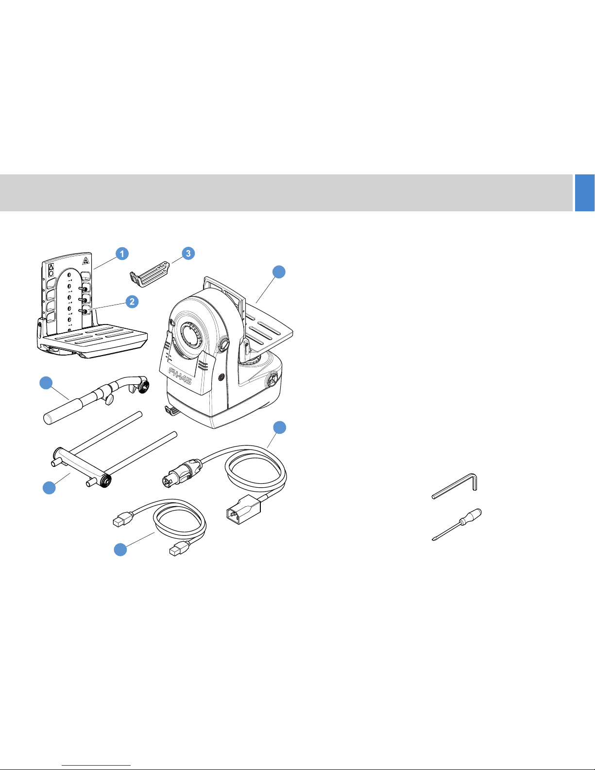
1 . . . . . . . . . . . . . . . . . . . . . . . . . . . . . . . . . . . . . Camera cradle
(comprising backplate and mounting plate)
2 . . . . . . . . . . . . . . . . . . . . . . . . . . . . . . . . . . Centre screws, x3
3 . . . . . . . . . . . . . . . . . . . . . Cable management bracket, large
4 . . . . . . . . . . . . . . . . . . . . .
5. . . . . . . . . . . . . . . . . . . . . . . . . . . . . . . . . . .
NI = Not illustrated
FH-145/FHR-145 pan and tilt head
Power cable, 3 m
6 . . . . . . . . . . . . . . . . . . . . . . . Ethernet cable, Cat5e FTP, 3 m
7. . . . . . . . . . . . . . . . . . . . . . . Pan bar assembly (FH-145 only)
(comprising rosette bar and two 400 mm rods)
8 . . . . . . . . . . . . . Pan bars, telescopic, black, x2 (FH-145 only)
NI. . . . . . . . . . . . . . . . . . . . . . . . . . . . . . . . Cable ties, black, x5
NI. . . . . . . . . . . . . . M4 countersunk screws (cable bracket), x3
NI . . . . 3/8" BSW x 3/4" cap head screws (camera screws), x2
NI . . . . . . . . . . . . . . . . . . . . . . . . . . . . 3/8" head fixing bolts, x4
NI . . . . . . . . . . . . . . . . . . . . . . . Vinten spanner (for head bolts)
NI . . . . . . . . . . . . . . . . . . . . . . . . . . . . . . . . . . Installation Guide
Tools required
5 mm Allen key
5/16" Allen key
5/64" Allen key
5
6
8
7
4
Flat-blade
screwdriver
Box Contents
6
FHR-35 Robotic Pan and Tilt Head
Installation
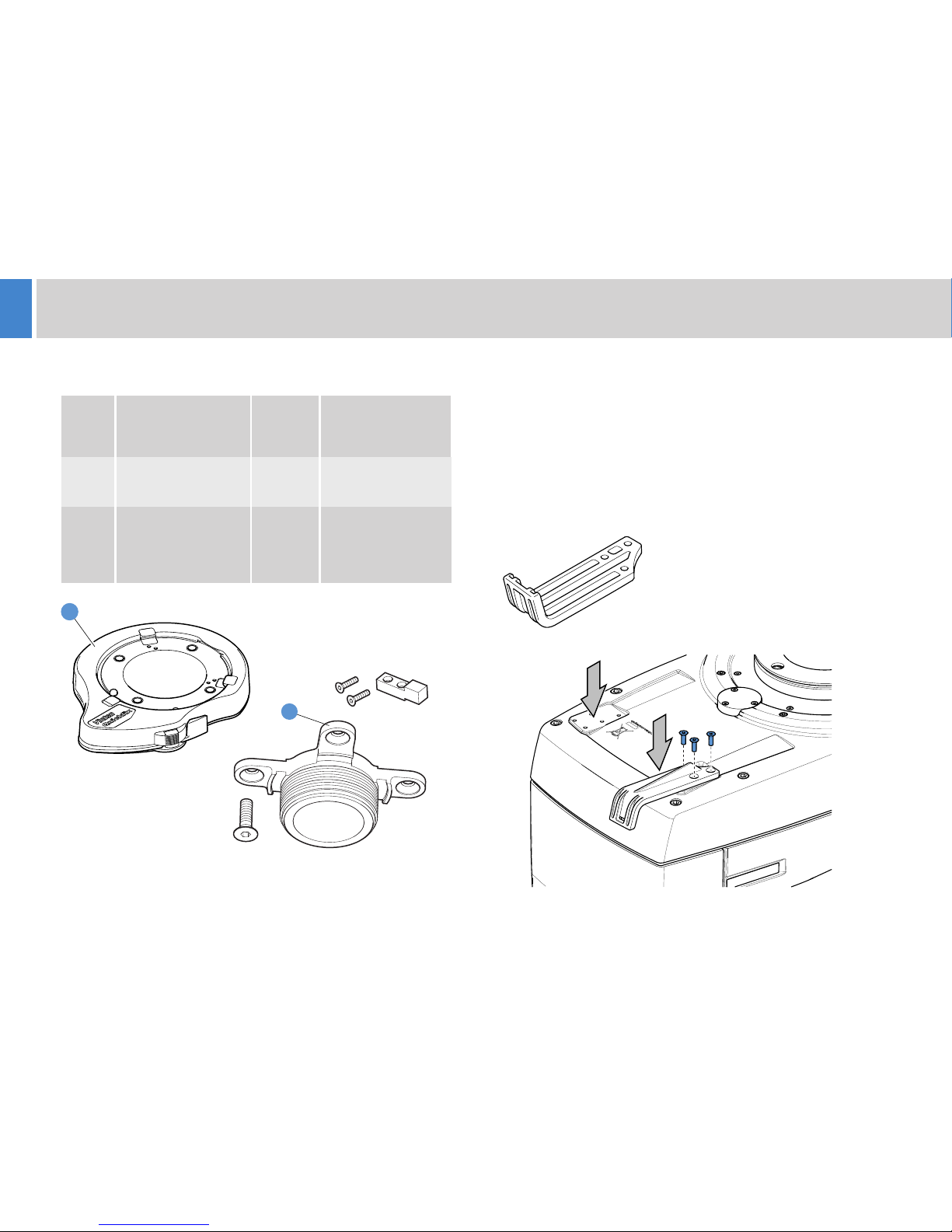
Mounting Supports and Adaptors Cable Management Brackets
ITEM
NO.
MOUNTING
SUPPORT OR
ADAPTOR
PART
NO.
MOUNT
1
Vinten HD Quickfix®
Adaptor
3490-3
Vinten HD tripods
2
Mitchell Centre
Screw (spider
adaptor with Mitchell
key)
3724-3
Vinten HD tripods
Sachtler OB2000
The FH-145/FHR-145 is supplied with a large cable manage-ment
bracket an be affixed on the left- or right-hand side and
to the front or back of the attachment point. Depending on the
camera and head setup, a second large cable management bracket
(see below) can also be fitted.
Camera and head connecting cables should be dressed and secured
to the bracket(s) to provide strain relief for the connectors.
. The bracket c
V4096-2082
2
1
7
FHR-35 Pan and Tilt HeadRoboticFHR-35 Robotic Pan and Tilt Head
Installation
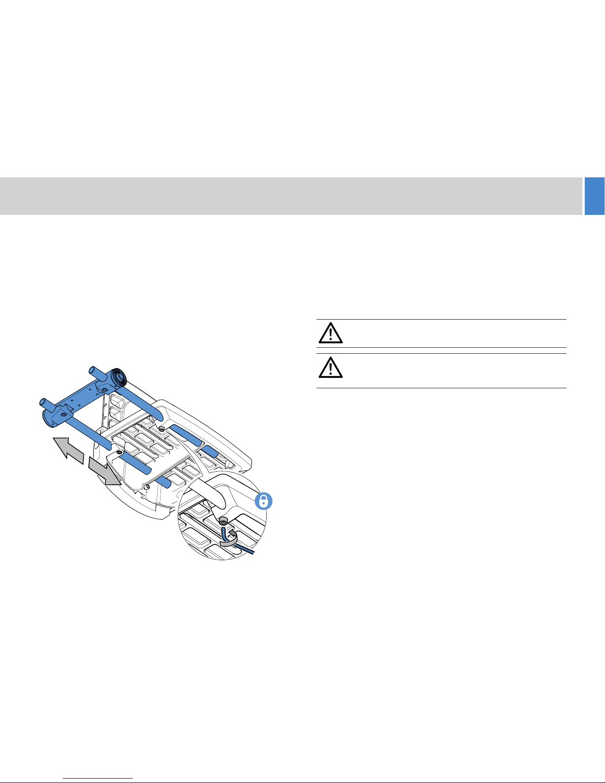
Mounting the Pan Bar Assembly (FH-145) HD Tripod Mounting Options
The FH-145/FHR-145 pan and tilt head can be mounted onto the
following heavy-duty (HD) tripods:
Ÿ Vinten HDT-1 single-stage tripod
Ÿ Vinten HDT-2 two-stage tripod
Ÿ Sachtler OB2000 aluminium tripod
Mount the head to the HD tripod using either a Mitchell Centre Screw
(spider adaptor) and key or a Vinten Quickfix® adaptor.
WARNING! Engage the tilt lock before lifting or working on
the head.
For manual operation, mount the pan bar assembly to the camera
cradle. Offset pan bars increase the range of movement and improve
manoeuverability of large and unwieldy payloads. The pan bar
assembly can be mounted on the left- or right-hand side of the
camera cradle.
1. Fit the pan bar assembly
to the cradle. Insert rods
into openings ensuring
they cross at least two
mounting points.
2. Tighten the screws
underneath the openings
to secure the assembly.
3. Attach the pan bars to
the rosette mountings.
CAUTION! Do not attempt to manually switch the pan or tilt
control switch to AUTO. Robotic mode must be initiated from
the control panel.
 Loading...