

Vinteck sas
Di Guido Michetti & C.
10128 Torino Corso Vittorio Emanuele II, 123
Tel. + 39 – 339 7626891 fax + 39 - 011 – 547712
Laboratorio Via Limone 22 10141 Torino
Nr. Iscrizione RAEE IT08020000002500
(web) http://www.vinteck.com
(e-mail) info@vinteck.com
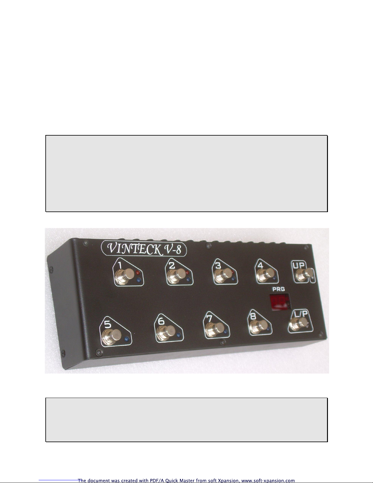
V-8
True-bypass MIDI switching Pedalboard
User manual
Ed. 01 rev. 0

Vinteck
V-8 – true-bypass MIDI switching pedalboard pag.2
Edition 01eng rev. 0
_______________________________________________________
Contents
1 Instrument’s marking page 2
2 gerneral wornings page 3
3 instructions manual page 3
4 technical description of V-UNO page 4
5 installation and connections (wiring) page 5
6 programming and MIDI manager page 8
7 spare parts page 10
8 warranty terms and conditions page 10
9 support page 10
_______________________________________________________________
1-instrument marking.
V-8 got in back side a little non removable area with serial and years of building.
It is very important to report this information in case of need of technical supply.
.
Thank you very much for purchase of V-8 pedalboard.
We really hope that it will be good friend for several ours of music. We ask you to
write us by email at support@vinteck.com any problems or any ideas about
hardware & software you think may be useful to us to built a better product.
We are anytime avalaible for any help you may need about how to use the V-UNO
Keep on rockin’ (blues, jazz, latin, fusion….)
Guido Michetti

Vinteck
V-8 – true-bypass MIDI switching pedalboard pag.3
Edition 01eng rev. 0
2- general wornings
o please read the operator manual before starting the use of V-8 and follow the
informations.
o Maintenance must be operated ALWAYS with the instrument not connected
to power supply
V-8 is powered by an external 12 VDC 500mA. In no any case external power supply
must be opened or dissasembled.
In no any case the power plug and switch must be disassembled.
Vinteck declines all responsibility for damages to persons, animals and things caused
by the non-observance of such a provision.
Warning
- Use of the machine by not properly trained staff.
- Improper use of the machine.
- Electric energy defects
- Repairing and changes made without authorisation.
- Use of not original or not specific for the model parts.
- Partial or total non-observance of the instructions.
- Use of the machine against national specific laws.
- Calamity and unusual events.
Remaining risk
Definition of remaining risk: “A danger not completely reducible from the designing and the
safety devices, i.e. potential and not evident danger”.
Since the productive aiming, the mechanical qualities and the presupposed proper usage we
didn’t find any remaining risks, both during the design and the tests.
Anyway, we recommend:
- to let only trained staff using the machine;
- to check that the machine is supplied by an grounded single-phase electrical cable and the
plug has an effective earth terminal.
3- instructions manual
3.1 This manual is addressed to following subjects:
- Owner;
- Operators.
- Technical builder
3.2 Aiming of details in I.M.
The manual contains a clear description of all technical specifications of the machine aimed
at the transport, adjusting, maintenance, caution, location of remaining risks.
3.3 Using limits of I.M.
This manual can never replace an adequate experience of an operator and so it can only be
a memorandum of the main operations. We specify, moreover. That I.M. mirrors the technical
data at the moment of the purchase of the machine and that the manufacturer has the right to
bring up-to-date I.M. and machines without conform I.M. and previous models.

Vinteck
V-8 – true-bypass MIDI switching pedalboard pag.4
Edition 01eng rev. 0
3.4 How to keep this I.M.
The operating instruction manual has to be kept in perfect state and has to be always
available for consultation. It has to follow the machine in case of transfer of property. It has to
be kept until the demolition of the machine itself,
To order the up-to-date versions of I.M. and for any further information, please contact
Vinteck sas or the nearest Vinteck sas dealer. We will be pleased to receive your
suggestions to improve our quality.
Note for the use of this machine in a foreign country: contingent laws and restrictions in place
for this kind of machine in the Country where it is used have to be respected also in the case
are not mentioned in this manual.
New updated release of the manual will be available on www.vinteck.com
4- V-8 : technical description
True bypass system, working with silver golden relays.
8 programmable loops, plus 2 extra loops for amps send return connections or non
automated effects.
It’s possible to connect 5 pedals in front of amps an 3 in effects loops, or 6 and 2.
4 programmable switch completely independent from loops, for amps channel control.
Any combination between loops, switch and MIDI program change is possible.
Buffered input, with on/off switch. Max input level +4dB
Out tuner
10 banks of 8 programs, total of 80 programs.
Each bank may be deactivated (from 0 to 9)
Direct activation of loops may be done with button program/loop
MIDI manager with possibility of program change assign from 0 to 100 on all programs,
independent from program number (MIDI MAPPING)
MIDI TAP TEMPO with external pedals, Control Change is assignable from 1 to 128.
MIDI channel manager input, output e 0/1 assignament.
MIDI IN and MIDI OUT with eco THRU (all incoming command comes send out as they are)
All programming operations may be done standing up.
2 digit Display
12 VDC not stabilized power supply, 500mA
Dimensions 33 x 12 cm. High 5,5 front, 6 cm back, staggered surface ad buttons positions,
for easy access.

Vinteck
V-8 – true-bypass MIDI switching pedalboard pag.5
Edition 01eng rev. 0
5- installation and connections (wiring)
All connection are on back side of V-8
Low, from left to right:
- BFR ON/OFF switch on or off the buffer on guitar buffer. Buffer must be switched off on case of signal higher
than +4 dB . IN case of use of pre buffered signal, just test best solution for you ear.
- IN Guitar, or bass, input
- TUNER Direct output from guitar IN. May be used for tuner. Note: there is not any MUTE function.-
- IN TRUE True bypass input. Any signal may be inserted..
- LOOP1-5 loops managed from buttons 1 to 5
SND Signal for pedal input
RTN Signal back from pedal.
- EXT LOOP Fixed loop. Usable for always ON pedals (ex volume) or for amp effect loop connection. (see
Example)
- LOOP6 loops managed from buttons 6
- EXT LOOP Fixed loop. Usable for always ON pedals (ex volume) or for amp effect loop connection. (see
Example)
- LOOP7-8 loops managed from buttons 7 and 8
- OUT OUTPUT signal
- EXSW input for external switch, temporary switch must be used.
- S 1-2-3-4 NO contact (normally open). Close HOT on GROUND. For amps channel switching.
- MIDI IN/OUT IN and OUT MIDI socket
- DC IN Power supply input. Not less than 12 VDC, 500mA (450mA required when all loops/switch are
active)
PEDALBOARD

Vinteck
V-8 – true-bypass MIDI switching pedalboard pag.6
Edition 01eng rev. 0
Leds show:;
- 1-8 BLUE loops 1 to 8
- S 1-4 YELLOW switch on/off 1, 2, 3 end 4 .
- P WHITE. Show PROGRAM MODE ON (programs will be recalled)
- L – BLU. Show LOOP MODE ON (loops will be recalled)
WARNING:
The light of the LEDS is very intense to allow visibility even under intense stage lights.
To avoid the risk of glare do not look directly into the light.
Vinteck declines all responsibility for damages to persons, animals and things caused
by the non-observance of such a provision
Button 1 - 8 may activate single loops or recalls programs, plus several MIDI
Button P/L make selection between LOOP e PROGRAMS, plus several MIDI functions
Button UP allows ratation of banks and selection of number od actve banks, plus MIDI functions,
WIRING AND CONNECTIONS EXAMPLES
V-8 must be powered with original power supply only.
Insert the power supply cord in his plug. When powered the V-UNO is active.
WORNING : never cut the wire of 230/12VAC power supply.
Never open the V-8 power supply. 230VAC inside when connected to 230 V socket.
Vinteck sas do not have any responsibility in case of damage to people, animals or objects in case of
non respect of this point. No warranty will be applied if power supply unit is disassembled or modified.
V-8 allows several way to connect to systems. You can see some example.
Note: examples are just examples, are not law. There are several possibilities to make good connections, just
found the best for you sound!
Example 1.
8 stomps chain and out to amp.

Vinteck
V-8 – true-bypass MIDI switching pedalboard pag.7
Edition 01eng rev. 0
Example 2
V-8 with 6 pedals in front and 3 in send/return.
Example 3
V-8 with 6 pedals in front, 2 pedals in send/return and volume in send/return before delays

Vinteck
V-8 – true-bypass MIDI switching pedalboard pag.8
Edition 01eng rev. 0
6 – PROGRAMMING AND MIDI MANAGER
BUTTON “L/P” AND BUTTON “UP”
L/P button
Make selection between LOOP and PROGRAM function of buttons 1 to 8
BLU led “L” ON button 1 to 8 make direct activation of loops
WHITE led ON button 1 to 8 recall programs
Other function:
whit white led “P” on, keep pressed for 3 seconds enter in MIDI MAPPING menu.
UP button
Whith white led “P” on, make increments of banks, if banks are active.
Keep pressed for decrease.
Other function:
Whit BLUE led ON keep pressed to enter in “activation of bank” function
PATCH PROGRAMMING
Programs allowed are 80, 10 banks of 8 programs.
To program combinations loops (1-8) – switch (1-4)
Whit white led ON:
Keep pressed the button of program (ex. Nr. 3) for about 2.5 seconds.
Programming is active when white led start to blink
Press buttons of loops desired. Blue led show active loops.
Keep pressed buttons 1-4 for about 2.5 secs to activate switches. Yellow led indicate switches ON.
Confirm and memorize programs pressing L/P button.
BANKS ACTIVATION
Factory preset comes with bans 1-9 not active. Only bank 0 is active.
To activate banks 1-9 .
With blue led “L” press and keep for about 4 secs button UP
Display shows b0 (bank zero)
Press UP to increase bank. Press button “L/P” to activate bank.
Active banks show on display the DOT.
Banks may be activated without sequence. (ex. Banks 0, 4 and 7 active).
Following display show T0, T1, T2, T3. This is a function not active on V-8
To exit and confirm press button 8.
MIDI SETTINGS
INPUT CHANNEL
Press buttons 1 and 5 together, keep pressed 3 secs.
Display blinks between IN and a number from 00 to 16.
00 is OMNI, 1 to 16 is channel selection of input.
Choose with buttons UP and L/P (as DOWN) , then confirm and exit with button 8.

Vinteck
V-8 – true-bypass MIDI switching pedalboard pag.9
Edition 01eng rev. 0
OUTPUT CHANNEL
Press buttons 2 and 6 together, keep pressed 3 secs.
Display blinks between OT (as OUT) and a number from 1 to 16.
1 to 16 is channel selection of output
Choose with buttons UP and L/P (as DOWN) , then confirm and exit with button 8.
Reference number 0-127 or 1/128
Press buttons 3 and 7 together, keep pressed 3 secs.
Display blinks between CH, and a number from 0 to 1
Choose with button UP and L/P (as down).
Effettuare la selezione con pulsanti UP e L/P (down).
Confirm and exit with button 8.
EXTERNAL BUTTONS FOR CONTROL CHANGE (MIDI TAP TEMPO)
With an external temporary Normally Open buttons it is possible to manage and send a Control
Change command via MIDI.
To set the CONTROL CHANGE value:
Press buttons 4 and 8 together, keep pressed 3 secs
Display blinks between CC, and a number from 0 to 99 then 0.0. to 2.8 for values from 100 to 128.
Choose value with buttons UP and L/P (as down) .
Preset values is CC #80 . On some devices this the preset as well. Check on users manual the right CC
values.
Confirm and exit with button 8.
PROGRAM CHANGE MIDI MAPPING.
V-8 allows to assign a PROGRAM CHANGE number difference from program number.
Factory preset got same number.
To change number:
Posizione V-8 con program ( 1 to 99)
NOTE: It’s important to remeber the number of program you’re working.
With white led “P” ON press L/P and keep pressed for 3 secs.
Display show a blinking number, which is the number of Program Change.
Use UP and L/P (as down) to define the new program change number.
Confirm and exit with button 8
FACTORY RESET
On V-8 it’s possible to return to beginning default settings.
To make Factory reset:
Shot down power supply, removing power supply cord
Press buttons 1 and 5 together, keep pressed and reinser power supply.
Display show “ii” , as Inizialization
Release buttons.
Note: Factory reset is not reversibile.

Vinteck
V-8 – true-bypass MIDI switching pedalboard pag.10
Edition 01eng rev. 0
7- Spare parts
Codice
descrizione
TB10S7
button
TB10BF
Buffer integrated chip
VUNOPS
External power supply
8- Warranty terms
V-8 is covered of total warranty of 2 (two) years from purchase.
Warranty operation will be performed only at Vinteck factory in Torino Italy.
Shipping cost are charged to customers
All operation and any spare parts are covered by warranty.
Warranty do not cover the following cases:
- Uncured utilization
- Damage from transportations
- Repairing and changes made without authorization
- Athmosferic Events
- Incorrect use of instruments
- Power supply not correct
- Use of not original spare parts
- Partial or total non-observance of the instructions;
- Use of the machine against national specific laws.;
- Calamity and unusual events.
10 support
Any information about “how to use” or any technical problems may be send by email to:
support@vinteck.com
or to
info@vinteck.com

Vinteck
V-8 – true-bypass MIDI switching pedalboard pag.11
Edition 01eng rev. 0
DECLARATION OF CONFORMITY
Application of Council Directive(s): 89/336/EEC and 93/68/EEC
Standard(s) to which Conformity is Declared EN 55103-1, EN 55103-2 and 60062: 1998
Manufacturer Vinteck SAS di Guido Michetti & C.
Corso Vittorio Emanuele II, 123
10128 Torino – ITALY
The equipment identified here conforms to
the Directive(s) and Standards specified
above
Type of equipment Effects switching system
Model TB10MKII – TB5
V-UNO V-8
Data september 2007
Vinteck sas
di Guido Michetti & C.
corso Vittorio Emanulele II 123
10128 Torino Italy
 Loading...