

Vinteck sas
Di Guido Michetti & C.
10128 Torino Corso Vittorio Emanuele II, 123
Tel. + 39 – 339 7626891 fax + 39 - 011 – 547712
Laboratorio Via Limone 22 10141 Torino
Nr. Iscrizione RAEE IT08020000002500
(web) http://www.vinteck.com
(e-mail) info@vinteck.com
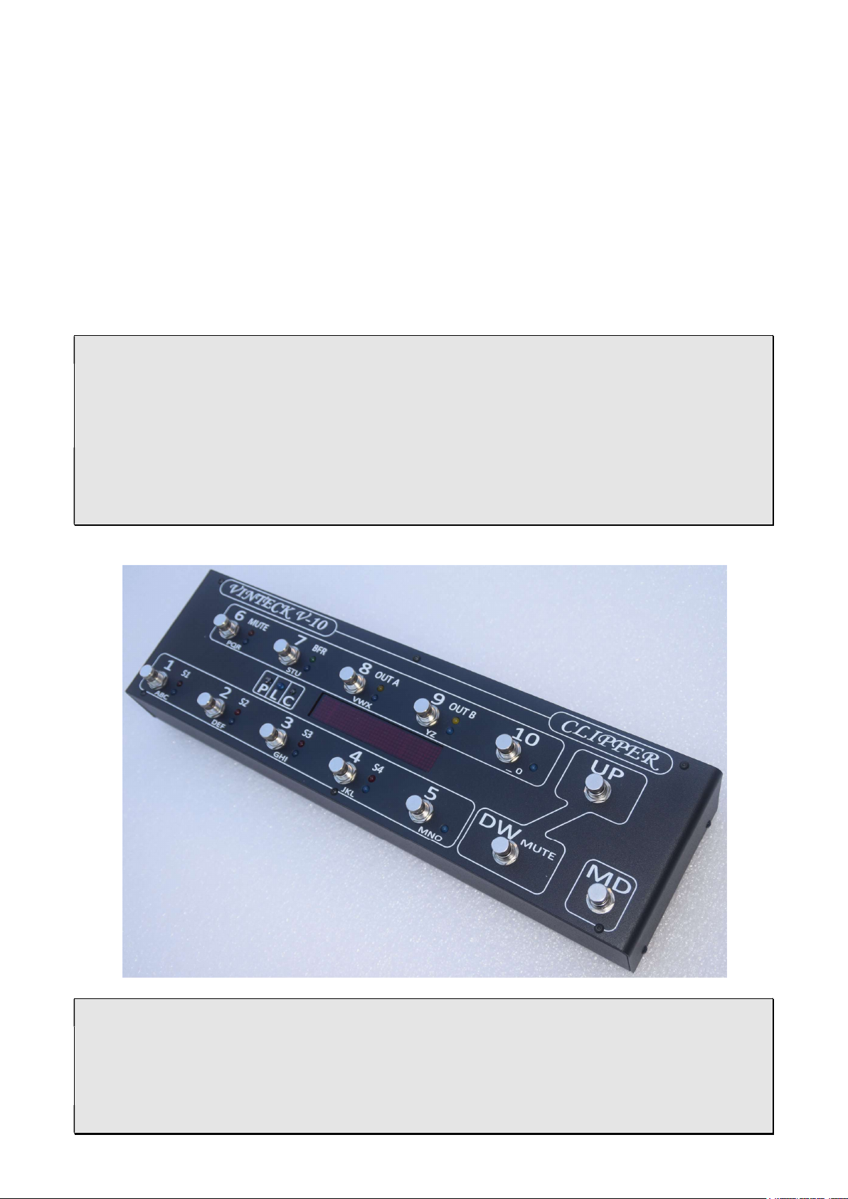
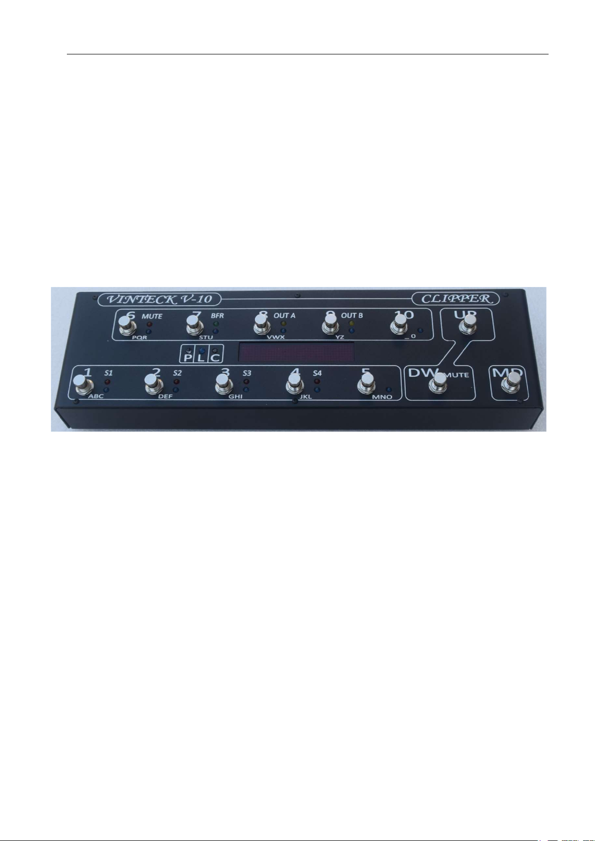
V-10 CLIPPER
True-bypass MIDI switching Pedalboard
User manual
Ed. 01 rev. 4
SW: DCEA - 0862

Vinteck
V-10 CLIPPER
pag.2
any problems or any ideas about
Thank you very much for purchase of V-8 pedalboard.
We really hope that it will be good friend for several ours of music. We ask you to
write us by email at support@vinteck.com
hardware & software you think may be useful to us to built a better product.
We are anytime avalaible for any help you may need about how to use the V-8
Keep on rockin’ (blues, jazz, latin, fusion….)
Guido Michetti
_______________________________________________________
Contents
1 Instrument’s marking pag. 2
2 general warnings pag. 3
3 instructions manual pag. 3
4 technical description pag. 4
5 installation and connections (wiring) pag. 5
6 programming and MIDI manager pag. 8
7 spare parts pag. 13
8 warranty terms and conditions pag. 14
9 support pag. 14
_______________________________________________________________
1-instrument marking.
V-10 got in back side a little non removable area with serial and years of building.
It is very important to report this information in case of need of technical supply.
2- general warnings
o please read the operator manual before starting the use of V-8 and follow the
informations.
o Maintenance must be operated ALWAYS with the instrument not connected
to power supply
Edizione 01 revisione0

Vinteck
V-10 CLIPPER
pag.3
V-8 is powered by an external 12 VDC 500mA. In no any case external power supply
must be opened or dissasembled.
In no any case the power plug and switch must be disassembled.
Vinteck declines all responsibility for damages to persons, animals and things caused
by the non-observance of such a provision.
Warning
- Use of the machine by not properly trained staff.
- Improper use of the machine.
- Electric energy defects
- Repairing and changes made without authorisation.
- Use of not original or not specific for the model parts.
- Partial or total non-observance of the instructions.
- Use of the machine against national specific laws.
- Calamity and unusual events.
Remaining risk
Definition of remaining risk: “A danger not completely reducible from the designing and the
safety devices, i.e. potential and not evident danger”.
Since the productive aiming, the mechanical qualities and the presupposed proper usage we
didn’t find any remaining risks, both during the design and the tests.
Anyway, we recommend:
- to let only trained staff using the machine;
- to check that the machine is supplied by an grounded single-phase electrical cable and the
plug has an effective earth terminal.
3- instructions manual
3.1 This manual is addressed to following subjects:
- Owner;
- Operators.
- Technical builder
3.2 Aiming of details in I.M.
The manual contains a clear description of all technical specifications of the machine aimed
at the transport, adjusting, maintenance, caution, location of remaining risks.
3.3 Using limits of I.M.
This manual can never replace an adequate experience of an operator and so it can only be
a memorandum of the main operations. We specify, moreover. That I.M. mirrors the technical
data at the moment of the purchase of the machine and that the manufacturer has the right to
bring up-to-date I.M. and machines without conform I.M. and previous models.
3.4 How to keep this I.M.
The operating instruction manual has to be kept in perfect state and has to be always
available for consultation. It has to follow the machine in case of transfer of property. It has to
be kept until the demolition of the machine itself,
To order the up-to-date versions of I.M. and for any further information, please contact
Vinteck sas or the nearest Vinteck sas dealer. We will be pleased to receive your
suggestions to improve our quality.
Edizione 01 revisione0
Vinteck
V-10 CLIPPER
pag.4
Note for the use of this machine in a foreign country: contingent laws and restrictions in place
for this kind of machine in the Country where it is used have to be respected also in the case
are not mentioned in this manual.
New updated release of the manual will be available on www.vinteck.com
4- V-10 CLIPPER : technical description
True bypass system, working with silver golden relays.
10 programmable loops, plus 2 extra loops for amps send return connections or non
automated effects. Loop 9 and 10 are stereo. A/B – A+B out controls.
It’s possible to connect 6 pedals in front of amps an 4 in effects loops, or 8 and 2. Otherwise,
all 10 in line in front of amp.
4 programmable switch completely independent from loops, for amps channel control.
Tuner OUT with MUTE Function MUTE activavle on flight, or programmed.
Programmable Buffer (max +4dB) indipendent for each patch.
Stereo OUT or programmable A/B A+B.
Any combination between loops, switch and MIDI program change is possible.
On any programs (1 to 120) it’s possible to assign any program change (MIDI MAPPING)
and up to 5 control change with independent channel and value.
12 banks, 10 programs each, total 120 programs.
Each bank may be activated or deactivated (form 0 to 11).
Direct acce on the fligh on loop, with MODE function program/loop
MIDI TAP TEMPO with external pedals, Control Change is assignable from 1 to 128.
MIDI channel manager input, output e 0/1 assignament.
MIDI external expression pedal managing, with Continuos control change
MIDI IN and MIDI OUT with eco THRU (all incoming command comes send out as they are)
High visibility LED display. 3 digit for programa number, up to 7 characters per program.
All programming operations may be done standing up.
External Power supply, 12 VAC or unstabilized DC, 600mA
Dimension 43 x 12 cm. High 4.5/6 cm.
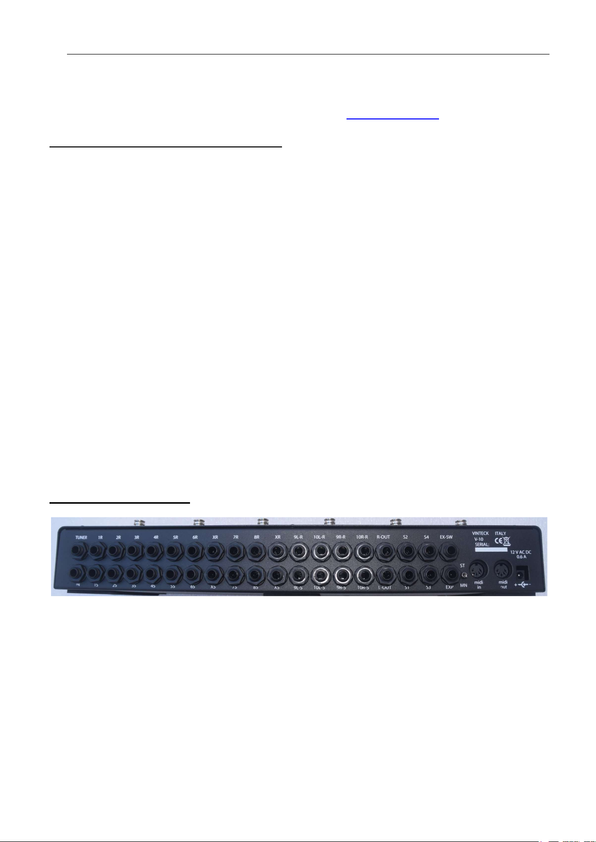
5- installation and wiring
All connection are on the back of V-10 CLIPPER
Low from right to left of image::
Power IN Power supplì input. 12VAC or DC 0.6 A (note: may ne power as well in AC or DC. It is possible
WARNING: Never open the external power supply. Inside there is 230 or 117 Volt power.
Opening of power supply is cause of warranty decline.
MIDI OUT MIDI out socket
MIDI IN MIDI IN socket
to use lower power supply of 0.6 A, keep in mind that in that case will be not possible to activate in
same time all switch and loops. When power is connected V10 Clipper is active.
Edizione 01 revisione0
Vinteck
V-10 CLIPPER
pag.5
MN ST MONO STEREO switch. (in MONO connections 9R-R/S e 10R-R/S (right canne) are
deactivated, only left channels works. OUTPUTS A and B got same signal coming fron 9 and 10
left loops.
EXT SW external tap tempo temporary input
Exd expression pedal inputo (25 Kohm raccomended)
S1-2-3-4 Normalli Open contacts. To be use for amp channel, or any similar application.
OUT R OUT L signal outputs. OUT L = OUT A, OUT R = OUT B (on pedals indicated as A and B)
- LOOP1-10 loops managed by buttons 1 to 10
S SEND Segnal to input of effetc
R RETURN Segnal back from effect.
- X LOOP fixed llops. Usable for send/return of alway active pedals (in ex volume pedal)
See schematics. .
- IN Guitar or bass INPUT
TUNER Tuner output. Always on even in MUTE.
PEDALBOARD
leds show:
- 1-10 BLUE: loop 1 to 10
- S 1-4 RED switch on/off 1, 2, 3 AND 4 .
- MUTE orange MUTE on.
- BFR GREEN buffer on
OUT A e
OUT B YELLOW outputs A (LEFT) and B (RIGHT) ON
- P WHITE : PROGRAM FUNCTION ACTIVE
- L – BLUE. LOOP function active
- C ORANGE shows a control change function active
Buttons 1-10 got dual function: activation of single loop or recall of programs. While in programs mode button
allows to program the switches 1-to 4, the buffer, the A and B out and may recall as well up to 5 control changes
and MIDI functions.
Edizione 01 revisione0

Vinteck
V-10 CLIPPER
pag.6
WIRING EXAMPLES
Followings schematis are only examples. Nor to be inted as LOW !!! Personal choise in sound building
is the only real referement!
Ex 1. 8 effects in front, 2 effects in send/return. Mono.
Edizione 01 revisione0

Vinteck
V-10 CLIPPER
pag.7
Ex 2
8 effects in front, 2 stereo effects in Send return on 2 amps. Line insulator on amp 2. Midi management and
expressione MIDI pedal.
Edizione 01 revisione0

Vinteck
V-10 CLIPPER
pag.8
Ex 3
8 effects in front, 2 couple of effects in stereo in fronte of 2 amps. Line insulator on amp 2.
Volume pedal after distorsion pedals.
Edizione 01 revisione0

Vinteck
V-10 CLIPPER
pag.9
6- USE AND PROGRAMMING OF V-10 CLIPPER. MIDI MANAGEMENT
FUNCTIONS OF “MD” BUTTON
MD button
Make selection between LOOP and PROGRAM function of buttons 1 to 10
BLU LED “L” ON buttons 1 to 10 make direct activation of single loops
WHITE led ON button 1 to 10 recall programs
Other function:
While in programming mode MD button gives SAVE function, then close procedure.
Holding pressed MD with WHITE LED “P” on MIDI MAPPING function is activated.
Holding pressed MD with BLUE LED “L” on V10 goes in GLOBAL.
BUTTON “UP” and “DW” FUNCTIONS
UP BUTTON
With WHITE LED “P” ON increments the banks, from 0 to 11, if banks are active.
Other functions
In programming mode allows input in “control change assign to patch”
With BLUE LED “L” ON, holding pressed allows access to “BANK ACTIVATION” function.
DW BUTTON
With WHITE LED “P” ON decrements the banks, from 0 to 11, if banks are active.
Other functions
In programming mode allows input in “PATCH NAME ON DISPLAY”
MUTE Function
MUTE (silence oc pedalboard, with TUNER out Active) is activable pressing DW while in LOOP
MODE
MUTE is also assignable to any patch, if needed.
Edizione 01 revisione0

Vinteck
V-10 CLIPPER
pag.10
ULT
1- 16
2 MIDI out canne,
MASTER
UP DW
1-16 MD 1 3 MIDI
numbering
0-127 / 1
-
128 UP DW
0 - 1 MD 1
Control Change
P6-
CC nr
0-
120 MD 000
P7- OUT channel
1-16 MD 1 P8-
CC value
0-
127 MD 000
255
P2-
LOW limit
0-
127 MD 000
P3-
HIGH limit
0-
127 MD 000 7 Buffer ON / OFF global
UP, DW
P10 MD
OFF
8
DUAL SHOT
OFF
GLOBAL FUNCTION
GLOBAL allows predefinition of following operative parameters, as in following table.
But
FUNCTION COMMAND 1 COMMAND 2 VALUE OUT
ton
SAVE
DEF
A
1 MIDI in channel UP DW 0 – omni
4 External Tap Tempo
5 Control Change assignament to
buttons 1 2 3 4 5
UP DW 0-127 MD 80
P1,P2,P3, P4,
P5
UP / DW
6 External expression pedal
Expression pedal calibration
P1,P 2, P3
UP, DW
P1- pedale value 0-255 MD 255-
Values assigament
9 Switch 1, 2, 3 e 4: latch, single
shot, dual shot
UP, DW
1,2,3,4
LATCH
SINGLE SHOT
MD LAT
10 BANKS activation UP, DW 1-10 ACTIVE
GLOBAL FUNTION ENTER
With blue led “L” press and hold MD for 4 seconds
Display show GLOBAL
Press button corresponding to wanted function
1- MIDI input channel
Display show MIDI IN followed by a number from 00 to 16.
00 is OMNI, all channels ON.
Make selection with UP and DW (down).
Save and exit with MD
2- MIDI output channe
Display show MIDI OUT followed by a number from 1 to 16
Make selection with UP and DW (down).
Save and exit with MD
Nota: this selection is general, may be changed for any control change
MD 0
CH
MD 1-on
Edizione 01 revisione0

Vinteck
V-10 CLIPPER
pag.11
3- Numbering of MIDI 0-127 / 1-128
Display show MIDI followed by a number from 0 to 1
0 = 0-127 , 1= 1-128
Make selection with UP and DW (down).
Save and exit with MD
4- External Tap Tempo Control Change value
With an external temporary button, to be connected to EX_SW, is possible to send a
CONTROLA CHANGE command for tap tempo in any moment, independent from programs.
Ant kind of temporary button may be used.
Top reset the CONTROL CHANGE:
Display show TAP follone by a number from 1 a 128
Make selection with UP and DW (down).
Save and exit with MD
Note: on same devices CC for tap is 80. Check on device user manual to preset the right value.
5- Control Changes assign to buttons 1-5, Value and channels
With this commando is possible assigb up to 5 control change to buttons 1, 2, 3, 4, 5 to be able
to recall them on patch.
The CC of button 5 is dedicated to Expression pedal
Display show CC1=000
Pressing buttons 1-5 shows respectively :
CC1=000
CC2=000
CC3=000
CC4=000
CC5=000
For each single button is possible assign the CC, the canne and the value.
Button 6 assign the nr of CC: UP e DW for selection, value from 1 to 120)
Display show CC1 : 000 ( from 000 to 120)
Button 7 asseign the CHANNEL of CC: UP e DW for selection, value from 1 to 16
Dispaly show CC CH 1 : 016 ( from 000 to 016)
Button 8 assign the VALUE of CC: UP e DW for selection, value from 0 to 127
Display show CCV1 : 000 ( from 000 to 127)
Note: for CC of button 5 values have to be preset in function 6
Save and exit with MD
Orange LED “C” blinks to show that you’re working on CC
6- External expression pedal calibration. CC value assignement.
Chose 1 (button 1): display show:
EXP 255 255
This is therangeof calibration of external expression pedal..
Move up and down the espressione pedal. Calibration is tuned. Value may be from 0 to 255
Display show EXP 255 255 (basic. After calibration may be 0 to 255)
Button 2 assign the CC LOWER END from 0 to 128. SMake selection with UP and DW
Display show EXP L : 000
- Button 2 assign the CC UPPER END from 0 to 128. SMake selection with UP and DW
Visualizzato EXP U : 000
Save and exit with MD
Edizione 01 revisione0

Vinteck
V-10 CLIPPER
pag.12
7- GLOBAL BUFFER ON/OFF
It is possible to activa or deactivate the buffer on all programs.
One by one it is possible the manage ON / OFF on any program.
Press 7 to select.
Display show ALL B ON or ALL B OFF
Press UP or DW to choose
Confirm selection with P10 ( button 10)
Display show for a while 001 a 120 followed by PROG ON
Do not sto anyway the sequence. It’s just take a while,
Sequence ends and exit automatically.
8- Unused.
9- Switch 1, 2, 3 and 4: latch, single shot, dual shot
The 4 switches for amp channels may be preset in 3 operation ways.
o Latch
o Single shot
o Dual shot (shot in ON , second shot in OFF)
From GLOBAL press button 9
Display show SW1 : LATCH
With buttons 1,2,3,4 make selection (swicth 1, 2, 3, 4)
With UP and DW select kind of: LATCH, SSHOT, DSHOT
Save and exit with MD
10- Bank activation
V-10 CLIPPER may meorize up to 12 banks, 10programs each.
For easy management it is possible to activate only some of 12 bancs.
Note: Not active banks keeps in menory patchs programmed.
O obtain activation of banks in GLOBAL choose 10
Display showa B00-ACTIVE
With UP and DW select banks, from 00 to 11
Presso any button (1 to 10) to change status OFF or ACTIVE
Save and exit with MD
Edizione 01 revisione0

Vinteck
V-10 CLIPPER
pag.13
PATCH PROGRAMMING
Available programs are 100. 10 patch for 10 banks.
On any programs (patch) it is posssible to assign:
- Any combination on/off of 10 loops
- Any combination on/off of 4 swicth
- buffer on/off
- out A , out B
- MUTE ( when MUTE is programmed no signal comes out from V-10 Clipper)
- MIDI program change (1-128) and out channel (1-16)
- Up to 5 Control Change (1-128) e related midi out channel OUT (1-16)
Programming Loops, switches, buffer, mute and A/B out
Whit white led “P” ON (selection with MD)
Hold button of choose program (from 1 to 10) . Keep it for about 3 seconds.
Blinkin of white led means that V-10 is in programming mode.
Press button of loops to be activated. Relative blue led will ON to show selection.
To select switches 1-4 keep pressed relative buttons (1, 2, 3, 4) for about 3 seconds up to red LED
switch light ON.
For BUFFER patch activation or deactivation press 7 and keep up to GREEN led come on or off .
For MUTE patch activation or deactivation press 7 and keep up to GREEN led come on or off .
OUT A and OUT B (relative to OUT L and OUT R in wiring) are always open (yellow led on)
To switches them OFF keep them pressed up to yellow leds comes OFF
Save and exit with MD
Chain up to 5 Control Change to one patch
While in programming of patch (WHITE LED LED BLINKING) press button UP.
Orange led will blink, to confirm assign procedure.
Pressing buttons 1 to 5 control change pre-assigned in GLOBAL (see GLOBAL 5), CC are chained
to patch program.
Display show CC 1 2 3 4 5 , followings preset done.
Save and exit with MD
To complete save procedure press once MD
PRESET NAME
While programmin (white led “P” blinking ) press DW
Procedure is similar to “sms text on phone”
Display show number of program (ex 001) followed by x……
Use the 1-10 buttons, following indication under button ( ex. 1= ABC1)
As soon as selected one letter display goes on following.
Max number of characters is 7 for any patch.
Save and exit with MD
To complete save procedure press once MD
Edizione 01 revisione0

Vinteck
V-10 CLIPPER
pag.14
PROGRAM CHANGE MIDI MAPPING.
Sofware release DCEA
It is possible to assign a PROGRAM CHANGE differento from patch number.
Default is program change = patch number.
To change program change:
While on the patch (ex 003, anyway 1 to 120) with white led “P” on :
Hold pressed MD for 3 secs
Display show : 001 PC : 000
Use UP and DW (down) to select desiderate Program change number
Selection is done.
Save and exit with MD
Note: when recalled a preset whit Control Change chained, the orange led will blink to show that
Control change are active and send.
PROGRAM CHANGE MIDI MAPPING. – ASSIGN OF 1, 2 or 3 PROGRAM CHANGE
Firmware release SW 0682
It is possible to assign up to 3 different POGRAM CHANGE on different CHANNELS for any single
program / patch , from 1 to 100
As default any program/patch got corrisponding PROGRAM CHANGE (1 = 1, 2= 2 etc)) and send
only 1 PC.
To set up PC anch channels:
Recall the program to modify (1 -100)
With white led “P” on, press MD ank keep pressed for 3 seconds.
Display show: 001 P1 : 001 (001-> patch P1-> progarm : 001 the number of CC)
With UP or DW it’s possible to change the PC from 1 to 128
Pressing pulsant “5” display show 001 CH1 : 01
Pressing UP or DW is possible to change the channel, from 1 to 16
Then:
pressing pulsant 2
display show 001 P2 : 000
with UP and DW is possible select from 1 to 128. 000 means NO PC
Press pulsant “6” display show 002 CH1 : 01
With UP and DW is possible to slect from 1 to 16
Then:
pressing pulsant 3
display show 001 P3 : 000
with UP and DW is possible select from 1 to 128. 000 means NO PC
Press pulsant “7” display show 003 CH1 : 01
With UP and DW is possible to slect from 1 to 16
Exit and save with MD
Edizione 01 revisione0

Vinteck
V-10 CLIPPER
pag.15
Codice
descrizione
FACTORY RESET
On V-10 CLIPPER8 it’s possible to return to beginning default settings.
To make Factory reset:
Shot down power supply, removing power supply cord
Press buttons 1 and 6 together, keep pressed and reinsert power supply.
Display show, after beginning on procedure, “FACTORY R” , as Initialization.
Release buttons.
Note: Factory reset is not reversible.
Warning: procedure may takes up to 20 seconds. Do not stop procedure and do not remove power
supply.
In case after 30 secs display stay off, or SW code remain fixed remove power supply. Than reinsert
power.
Procedure may needs two times of power on and OFF.
Factory reset is not reversible.
7-Spare parts
TB10S7 Button
TB10BF Buffer integrated circuit
V-Series-PS External power supply
8-warranty and terms
V-10 CLIPPER is covered by warranty for 24 mounth from purchase
Aany warranty will be made at the vinteck labs
Lab: via Limone 22 – 10141 Torino Italy
Shipping cost are charged to customers after 1 year.
All operation and any spare parts are covered by warranty.
Warranty do not cover the following cases:
- Uncured utilization
- Damage from transportations
- Repairing and changes made without authorization
- Athmosferic Events
- Incorrect use of instruments
- Power supply not correct
- Use of not original spare parts
- Partial or total non-observance of the instructions;
- Use of the machine against national specific laws.;
- Calamity and unusual events.
Edizione 01 revisione0

Vinteck
V-10 CLIPPER
pag.16
9 support
Any information about “how to use” or any technical problems may be send by email to:
support@vinteck.com
or to
info@vinteck.com
DECLARATION OF CONFORMITY
Application of Councl Directive(s): 89/336/EEC and 93/68/EEC
Standard(s) to which Conformity is Daclared EN 55103-1, EN 55103-2 and 60062: 1998
Manufacturer Vinteck SAS di Guido Michetti & C.
Corso Vittorio Emanuele II, 123
10128 Torino – ITALY
The equipment identified here conforms to
the Directive(s) and Standards specifed above
Type of equipment Effects switching system
Model TB10MKII – TB5+
V-UNO- V-8 , V-5, V10
Data september 2007
Vinteck sas
di Guido Michetti & C.
corso Vittorio Emanulele II 123
10128 Torino Italy
Edizione 01 revisione0
 Loading...