

Page 1

Wall Strip Presentation Rack
(WS-PR) Installation Instructions
Wine Master Cellars • 10645 E 47th Ave, Denver, CO 80239 • phone: 866.650.1500 • fax: 866.650.1501
Please feel free to contact us regarding the assembly of this product.
Each WS-PR kit contains:
• 1 Wall Strip Presentation Rack (WS-PR)
• 8 Plastic Mounting Hole Caps (Bagged)
Before starting, open all Packaging for the WS-PR and take inventory to make sure you have everything.
• 5 Plastic Couplers (Bagged)
• 6 Plastic End Caps (Installed)
Tools Needed:
• Level
• Marking Pen or Pencil (Necessary in Some Cases)
• The appropriate FASTENERS for the wall surface you are attaching the WS-PR to.
• Tape Measure (Necessary in Some Cases)
• Phillips Head Power Screwdriver
Fasteners:
There are eight pre-drilled Mounting Holes for fasteners on each WS-PR Series Rack. It is strongly recommended that
appropriate fasteners be used in every Mounting Hole. We do not include fasteners with your WS-PR. However, we
recommend the following fasteners for these surfaces:
• Wood Surface: #8 x 1-1/4” wood screw
• Drywall/Wallboard Surface: #8 x 1-1/4” screw with spiral inserts and/or
expanding hollow wall anchors such as toggle bolts
• Concrete, Brick or Stucco: 3/16” x 1 ¾” masonry screw or expanding anchor
NOTE: If you are attaching the WS-PR to a VintageView® Floor to Ceiling Frame (FCF) you will attach the WS-PR to
the FCF using the self-drilling screws included in the FCF packaging.
WS-PR Installation Instructions
NOTE: If you are installing the WS-PR to a wall or FCF above or below a WS-3 or WS-4 Series Rack System:
Install the WS Series Racks before installing the WS-PR.
Installation to a Wall
1 - Installation to a Wall above WS Series Racks
1.1 Remove the Black Plastic End Cap that is inserted into the
bottom of each of the four Mounting Braces on the WS-PR.
NOTE: If you will be installing the WS-PR next to other WS-
PRs also remove the Black Plastic End Caps on both sides of
the WS-PR and insert a Black Plastic Coupler to one side of
the WS-PR.
1.2 Remove the Black Plastic End Caps from the top of the
WS Series Racks that correspond to the Mounting Braces on
the WS-PR.
1.3 Insert the Black Plastic Couplers into the top of the WS
Series Strips.
1.4 Align the WS-PR Mounting Braces directly over the WS Wall
Strips and attach to the Wall Strips by sliding the WS-PR onto
the Couplers xed into the WS Series Strips.
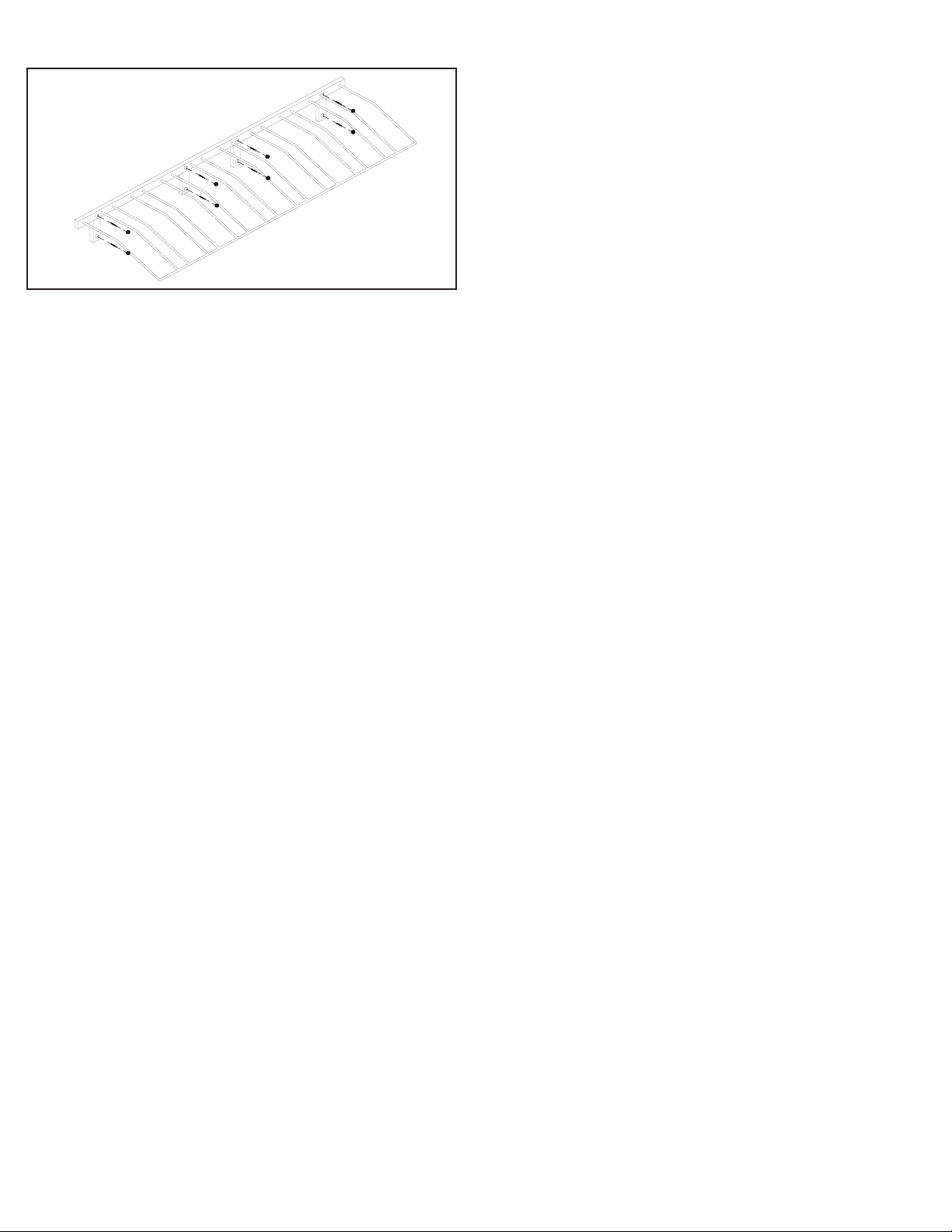
1.5 Using the Appropriate Fasteners; mount the WS-PR to the wall
through the hole in each of the 4 WS-PR Mounting Braces, and the
hole above each Mounting Brace.
1.6 Attach the Black Plastic Mounting Hole Caps over the fasteners in
the 8 Mounting Hole
2 – Installation to a Wall below WS Series Racks
NOTE: If you will be installing the WS-PR next to other WS-PRs
remove the Black Plastic End Caps on both sides of the WS-PR and
insert a Black Plastic Coupler into one side of the WS-PR.
(Continued on back of sheet).
Page 2
Installation to a Wall (cont.)
2.1 Align the WS-PR below the WS Series Wall Strips and make note
of the Wall Strips that correspond to the Mounting Braces of the
WS-PR.
2.2 With a tape measure, measure 8 inches down from the bottom
of the two outermost corresponding Wall Strips of the WS Series
Racks that are placed above the location you wish to install the WS-
PR. Mark those spots on the wall with a marking pen or pencil.
2.3 Align the bottom of the legs of the Mounting Braces to the
marks that you made.
2.4 Using the appropriate fastener mount the WS-PR to the wall
through one of the outer Mounting Holes. Do Not fully Tighten.
2.5 Using a level make sure that the WS-PR is level and then mark
the wall through the other seven Mounting Holes with a marking
pen or pencil.
2.6 Mount the WS-PR to the wall with the fasteners through the
seven remaining Mounting Holes on the WS-PR to the locations indi-
cated by your markings. Fully tighten all fasteners.
2.7 Attach the Black Plastic Mounting Hole Caps over the fasteners
in the 8 Mounting Holes.
3 – Installation to a Wall with no WS Series Racks
NOTE: If you will be installing the WS-PR next to other WS-PRs
remove the Black Plastic End Caps on both sides of the WS-PR and
insert a Black Plastic Coupler into one side of the WS-PR.
3.1 Place the WS-PR against the wall where you would like to install
it and attach one appropriate fastener to the wall through a Mount-
ing Hole on the WS-PR. Do not fully tighten.
3.2 Using a level make sure that the WS-PR is level and then mark
the wall through the other seven Mounting Holes with a marking pen
or pencil.
3.3 Mount the WS-PR to the wall with the fasteners through the
seven remaining Mounting Holes on the WS-PR to the locations indi-
cated by your markings. Fully tighten all fasteners.
3.4 Attach the Black Plastic Mounting Hole Caps over the fasteners
in the 8 Mounting Holes.
Installation to an FCF
1 - Installation to an FCF above WS Series Racks
1.1 Remove the Black Plastic End Cap that is attached to the bottom
each of the four Mounting Braces on the WS-PR.
NOTE: If you will be installing the WS-PR next to other WS-PRs also
remove the Black Plastic End Caps on both sides of the WS-PR and
insert a Black Plastic Coupler into one side of the WS-PR.
1.2 Remove the Black Plastic End Caps on top of the vertical Strips
attached to the FCF of the WS Series Racks that correspond to the
Mounting Braces on the WS-PR.
1.3 Insert the Black Plastic Couplers into the top of the WS Series
Strips. 1.4 Align the WS-PR Mounting Braces directly over the WS
Series Strips and attach to the Strips by sliding the WS-PR onto the
Couplers xed into the WS Series Strips.
1.5 Using the Self-drilling Screws; mount the WS-PR to the FCF
through the Mounting Hole in each of the 4 WS-PR Mounting Braces,
and the Mounting Hole above each Mounting Brace.
1.6 Attach the Black Plastic Mounting Hole Caps over the Self-Tapping
Screws in the 8 Mounting Holes.
2 – Installation to an FCF below WS Series Racks
NOTE: If you will be installing the WS-PR next to other WS-PRs
remove the Black Plastic End Caps on both sides of the WS-PR and
attach a Black Plastic Coupler to one side of the WS-PR.
2.1 Align the WS-PR below the WS Series Strips and make note of
the Strips that correspond to the Mounting Braces of the WS-PR.
2.2 With a tape measure, measure 8 inches down from the bottom
of the two outermost corresponding Strips of the WS Series Racks
that are placed above the location you wish to install the WS-PR.
Mark those spots on the FCF with a marking pen or pencil.
2.3 Align the bottom of the legs of the Mounting Braces to the marks
that you made.
2.4 Using the Self-drilling Screws mount the WS-PR to the FCF
through one of the outer Mounting Holes. Do Not fully Tighten.
2.5 Using a level make sure that the WS-PR is level and then mark
the FCF through the other seven Mounting Holes with a marking pen
or pencil.
2.6 Mount the WS-PR to the FCF with the Self-drilling Screws
through the seven remaining Mounting Holes on the WS-PR to the
locations indicated by your markings. Fully tighten all Self-drilling
Screws.
2.7 Attach the Black Plastic Mounting Hole Caps over the Self-drilling
Screws in the 8 Mounting Holes.
3 – Installation to an FCF with no WS Series Racks
NOTE: If you will be installing the WS-PR next to other WS-PRs also
remove the Black Plastic End Caps on both sides of the WS-PR and
attach a Black Plastic Coupler to one side of the WS-PR.
3.1 Place the WS-PR against the FCF where you would like to install
it and attach one Self-Tapping Screw to the FCF through a Mounting
Hole on the WS-PR. Do not fully tighten.
3.2 Using a level make sure that the WS-PR is level and then mark
the FCF through the other seven Mounting Holes with a marking pen
or pencil.
3.3 Mount the WS-PR to the FCF with the Self-drilling Screws
through the seven remaining Mounting Holes on the WS-PR to the
locations indicated by your markings. Fully tighten all Self-drilling
Screws.
3.4 Attach the Black Plastic Mounting Hole Caps over the Self-drilling
Screws in the 8 Mounting Holes.
 Loading...